EP3472919B1 - Dispositif portatif de dévidage d'un câble électrique, notamment un câble de charge pour un véhicule électrique ou hybride - Google Patents
Dispositif portatif de dévidage d'un câble électrique, notamment un câble de charge pour un véhicule électrique ou hybride Download PDFInfo
- Publication number
- EP3472919B1 EP3472919B1 EP17734793.7A EP17734793A EP3472919B1 EP 3472919 B1 EP3472919 B1 EP 3472919B1 EP 17734793 A EP17734793 A EP 17734793A EP 3472919 B1 EP3472919 B1 EP 3472919B1
- Authority
- EP
- European Patent Office
- Prior art keywords
- cable
- support
- cover
- spiral
- groove
- Prior art date
- Legal status (The legal status is an assumption and is not a legal conclusion. Google has not performed a legal analysis and makes no representation as to the accuracy of the status listed.)
- Active
Links
Images



Classifications
-
- H—ELECTRICITY
- H02—GENERATION; CONVERSION OR DISTRIBUTION OF ELECTRIC POWER
- H02G—INSTALLATION OF ELECTRIC CABLES OR LINES, OR OF COMBINED OPTICAL AND ELECTRIC CABLES OR LINES
- H02G11/00—Arrangements of electric cables or lines between relatively-movable parts
- H02G11/02—Arrangements of electric cables or lines between relatively-movable parts using take-up reel or drum
-
- B—PERFORMING OPERATIONS; TRANSPORTING
- B60—VEHICLES IN GENERAL
- B60L—PROPULSION OF ELECTRICALLY-PROPELLED VEHICLES; SUPPLYING ELECTRIC POWER FOR AUXILIARY EQUIPMENT OF ELECTRICALLY-PROPELLED VEHICLES; ELECTRODYNAMIC BRAKE SYSTEMS FOR VEHICLES IN GENERAL; MAGNETIC SUSPENSION OR LEVITATION FOR VEHICLES; MONITORING OPERATING VARIABLES OF ELECTRICALLY-PROPELLED VEHICLES; ELECTRIC SAFETY DEVICES FOR ELECTRICALLY-PROPELLED VEHICLES
- B60L53/00—Methods of charging batteries, specially adapted for electric vehicles; Charging stations or on-board charging equipment therefor; Exchange of energy storage elements in electric vehicles
- B60L53/10—Methods of charging batteries, specially adapted for electric vehicles; Charging stations or on-board charging equipment therefor; Exchange of energy storage elements in electric vehicles characterised by the energy transfer between the charging station and the vehicle
- B60L53/14—Conductive energy transfer
- B60L53/16—Connectors, e.g. plugs or sockets, specially adapted for charging electric vehicles
-
- B—PERFORMING OPERATIONS; TRANSPORTING
- B65—CONVEYING; PACKING; STORING; HANDLING THIN OR FILAMENTARY MATERIAL
- B65H—HANDLING THIN OR FILAMENTARY MATERIAL, e.g. SHEETS, WEBS, CABLES
- B65H75/00—Storing webs, tapes, or filamentary material, e.g. on reels
- B65H75/02—Cores, formers, supports, or holders for coiled, wound, or folded material, e.g. reels, spindles, bobbins, cop tubes, cans, mandrels or chucks
- B65H75/18—Constructional details
- B65H75/26—Arrangements for preventing slipping of winding
- B65H75/265—Reels with grooves or grooved elements inhibiting aligned or orderly winding
-
- B—PERFORMING OPERATIONS; TRANSPORTING
- B65—CONVEYING; PACKING; STORING; HANDLING THIN OR FILAMENTARY MATERIAL
- B65H—HANDLING THIN OR FILAMENTARY MATERIAL, e.g. SHEETS, WEBS, CABLES
- B65H75/00—Storing webs, tapes, or filamentary material, e.g. on reels
- B65H75/02—Cores, formers, supports, or holders for coiled, wound, or folded material, e.g. reels, spindles, bobbins, cop tubes, cans, mandrels or chucks
- B65H75/34—Cores, formers, supports, or holders for coiled, wound, or folded material, e.g. reels, spindles, bobbins, cop tubes, cans, mandrels or chucks specially adapted or mounted for storing and repeatedly paying-out and re-storing lengths of material provided for particular purposes, e.g. anchored hoses, power cables
- B65H75/38—Cores, formers, supports, or holders for coiled, wound, or folded material, e.g. reels, spindles, bobbins, cop tubes, cans, mandrels or chucks specially adapted or mounted for storing and repeatedly paying-out and re-storing lengths of material provided for particular purposes, e.g. anchored hoses, power cables involving the use of a core or former internal to, and supporting, a stored package of material
- B65H75/40—Cores, formers, supports, or holders for coiled, wound, or folded material, e.g. reels, spindles, bobbins, cop tubes, cans, mandrels or chucks specially adapted or mounted for storing and repeatedly paying-out and re-storing lengths of material provided for particular purposes, e.g. anchored hoses, power cables involving the use of a core or former internal to, and supporting, a stored package of material mobile or transportable
- B65H75/406—Cores, formers, supports, or holders for coiled, wound, or folded material, e.g. reels, spindles, bobbins, cop tubes, cans, mandrels or chucks specially adapted or mounted for storing and repeatedly paying-out and re-storing lengths of material provided for particular purposes, e.g. anchored hoses, power cables involving the use of a core or former internal to, and supporting, a stored package of material mobile or transportable hand-held during use
-
- B—PERFORMING OPERATIONS; TRANSPORTING
- B65—CONVEYING; PACKING; STORING; HANDLING THIN OR FILAMENTARY MATERIAL
- B65H—HANDLING THIN OR FILAMENTARY MATERIAL, e.g. SHEETS, WEBS, CABLES
- B65H75/00—Storing webs, tapes, or filamentary material, e.g. on reels
- B65H75/02—Cores, formers, supports, or holders for coiled, wound, or folded material, e.g. reels, spindles, bobbins, cop tubes, cans, mandrels or chucks
- B65H75/34—Cores, formers, supports, or holders for coiled, wound, or folded material, e.g. reels, spindles, bobbins, cop tubes, cans, mandrels or chucks specially adapted or mounted for storing and repeatedly paying-out and re-storing lengths of material provided for particular purposes, e.g. anchored hoses, power cables
- B65H75/38—Cores, formers, supports, or holders for coiled, wound, or folded material, e.g. reels, spindles, bobbins, cop tubes, cans, mandrels or chucks specially adapted or mounted for storing and repeatedly paying-out and re-storing lengths of material provided for particular purposes, e.g. anchored hoses, power cables involving the use of a core or former internal to, and supporting, a stored package of material
- B65H75/44—Constructional details
- B65H75/4402—Guiding arrangements to control paying-out and re-storing of the material
-
- B—PERFORMING OPERATIONS; TRANSPORTING
- B65—CONVEYING; PACKING; STORING; HANDLING THIN OR FILAMENTARY MATERIAL
- B65H—HANDLING THIN OR FILAMENTARY MATERIAL, e.g. SHEETS, WEBS, CABLES
- B65H75/00—Storing webs, tapes, or filamentary material, e.g. on reels
- B65H75/02—Cores, formers, supports, or holders for coiled, wound, or folded material, e.g. reels, spindles, bobbins, cop tubes, cans, mandrels or chucks
- B65H75/34—Cores, formers, supports, or holders for coiled, wound, or folded material, e.g. reels, spindles, bobbins, cop tubes, cans, mandrels or chucks specially adapted or mounted for storing and repeatedly paying-out and re-storing lengths of material provided for particular purposes, e.g. anchored hoses, power cables
- B65H75/38—Cores, formers, supports, or holders for coiled, wound, or folded material, e.g. reels, spindles, bobbins, cop tubes, cans, mandrels or chucks specially adapted or mounted for storing and repeatedly paying-out and re-storing lengths of material provided for particular purposes, e.g. anchored hoses, power cables involving the use of a core or former internal to, and supporting, a stored package of material
- B65H75/44—Constructional details
- B65H75/4402—Guiding arrangements to control paying-out and re-storing of the material
- B65H75/4405—Traversing devices; means for orderly arranging the material on the drum
- B65H75/441—Traversing devices; means for orderly arranging the material on the drum with a handle on the guide for manual operation
-
- B—PERFORMING OPERATIONS; TRANSPORTING
- B65—CONVEYING; PACKING; STORING; HANDLING THIN OR FILAMENTARY MATERIAL
- B65H—HANDLING THIN OR FILAMENTARY MATERIAL, e.g. SHEETS, WEBS, CABLES
- B65H75/00—Storing webs, tapes, or filamentary material, e.g. on reels
- B65H75/02—Cores, formers, supports, or holders for coiled, wound, or folded material, e.g. reels, spindles, bobbins, cop tubes, cans, mandrels or chucks
- B65H75/34—Cores, formers, supports, or holders for coiled, wound, or folded material, e.g. reels, spindles, bobbins, cop tubes, cans, mandrels or chucks specially adapted or mounted for storing and repeatedly paying-out and re-storing lengths of material provided for particular purposes, e.g. anchored hoses, power cables
- B65H75/38—Cores, formers, supports, or holders for coiled, wound, or folded material, e.g. reels, spindles, bobbins, cop tubes, cans, mandrels or chucks specially adapted or mounted for storing and repeatedly paying-out and re-storing lengths of material provided for particular purposes, e.g. anchored hoses, power cables involving the use of a core or former internal to, and supporting, a stored package of material
- B65H75/44—Constructional details
- B65H75/4402—Guiding arrangements to control paying-out and re-storing of the material
- B65H75/4405—Traversing devices; means for orderly arranging the material on the drum
- B65H75/4415—Guiding ribs on the drum
-
- B—PERFORMING OPERATIONS; TRANSPORTING
- B65—CONVEYING; PACKING; STORING; HANDLING THIN OR FILAMENTARY MATERIAL
- B65H—HANDLING THIN OR FILAMENTARY MATERIAL, e.g. SHEETS, WEBS, CABLES
- B65H75/00—Storing webs, tapes, or filamentary material, e.g. on reels
- B65H75/02—Cores, formers, supports, or holders for coiled, wound, or folded material, e.g. reels, spindles, bobbins, cop tubes, cans, mandrels or chucks
- B65H75/34—Cores, formers, supports, or holders for coiled, wound, or folded material, e.g. reels, spindles, bobbins, cop tubes, cans, mandrels or chucks specially adapted or mounted for storing and repeatedly paying-out and re-storing lengths of material provided for particular purposes, e.g. anchored hoses, power cables
- B65H75/38—Cores, formers, supports, or holders for coiled, wound, or folded material, e.g. reels, spindles, bobbins, cop tubes, cans, mandrels or chucks specially adapted or mounted for storing and repeatedly paying-out and re-storing lengths of material provided for particular purposes, e.g. anchored hoses, power cables involving the use of a core or former internal to, and supporting, a stored package of material
- B65H75/44—Constructional details
- B65H75/4457—Arrangements of the frame or housing
- B65H75/4471—Housing enclosing the reel
-
- B—PERFORMING OPERATIONS; TRANSPORTING
- B65—CONVEYING; PACKING; STORING; HANDLING THIN OR FILAMENTARY MATERIAL
- B65H—HANDLING THIN OR FILAMENTARY MATERIAL, e.g. SHEETS, WEBS, CABLES
- B65H2701/00—Handled material; Storage means
- B65H2701/30—Handled filamentary material
- B65H2701/34—Handled filamentary material electric cords or electric power cables
-
- Y—GENERAL TAGGING OF NEW TECHNOLOGICAL DEVELOPMENTS; GENERAL TAGGING OF CROSS-SECTIONAL TECHNOLOGIES SPANNING OVER SEVERAL SECTIONS OF THE IPC; TECHNICAL SUBJECTS COVERED BY FORMER USPC CROSS-REFERENCE ART COLLECTIONS [XRACs] AND DIGESTS
- Y02—TECHNOLOGIES OR APPLICATIONS FOR MITIGATION OR ADAPTATION AGAINST CLIMATE CHANGE
- Y02T—CLIMATE CHANGE MITIGATION TECHNOLOGIES RELATED TO TRANSPORTATION
- Y02T10/00—Road transport of goods or passengers
- Y02T10/60—Other road transportation technologies with climate change mitigation effect
- Y02T10/70—Energy storage systems for electromobility, e.g. batteries
-
- Y—GENERAL TAGGING OF NEW TECHNOLOGICAL DEVELOPMENTS; GENERAL TAGGING OF CROSS-SECTIONAL TECHNOLOGIES SPANNING OVER SEVERAL SECTIONS OF THE IPC; TECHNICAL SUBJECTS COVERED BY FORMER USPC CROSS-REFERENCE ART COLLECTIONS [XRACs] AND DIGESTS
- Y02—TECHNOLOGIES OR APPLICATIONS FOR MITIGATION OR ADAPTATION AGAINST CLIMATE CHANGE
- Y02T—CLIMATE CHANGE MITIGATION TECHNOLOGIES RELATED TO TRANSPORTATION
- Y02T10/00—Road transport of goods or passengers
- Y02T10/60—Other road transportation technologies with climate change mitigation effect
- Y02T10/7072—Electromobility specific charging systems or methods for batteries, ultracapacitors, supercapacitors or double-layer capacitors
-
- Y—GENERAL TAGGING OF NEW TECHNOLOGICAL DEVELOPMENTS; GENERAL TAGGING OF CROSS-SECTIONAL TECHNOLOGIES SPANNING OVER SEVERAL SECTIONS OF THE IPC; TECHNICAL SUBJECTS COVERED BY FORMER USPC CROSS-REFERENCE ART COLLECTIONS [XRACs] AND DIGESTS
- Y02—TECHNOLOGIES OR APPLICATIONS FOR MITIGATION OR ADAPTATION AGAINST CLIMATE CHANGE
- Y02T—CLIMATE CHANGE MITIGATION TECHNOLOGIES RELATED TO TRANSPORTATION
- Y02T90/00—Enabling technologies or technologies with a potential or indirect contribution to GHG emissions mitigation
- Y02T90/10—Technologies relating to charging of electric vehicles
- Y02T90/14—Plug-in electric vehicles
Definitions
- the present invention relates to a portable device for unwinding an electric cable, in particular a charging cable for an electric or hybrid vehicle.
- Li-ion lithium-ion cells
- V the voltage levels required at the terminals of the battery
- V the order 400 volts
- the necessary recharging power levels of the order of 2 to 3 kilowatt-hours in slow charge for several hours, up to several tens of kilowatt-hours in rapid charge for a few tens of minutes.
- the charging cable itself is subjected to high stresses.
- the most well-known solution which is also the simplest, is to provide a “flywheel” charging cable with a wide section adapted to the maximum load power envisaged, which is transported in the boot of the vehicle.
- the main drawback of this solution is that, during the charging phases, the cable drags on the ground and becomes dirty. So either the user folds it neatly (which can be complicated given its large section) before storing it in his trunk and it gets his hands dirty, or he puts it loose in the trunk and it there is a significant risk that he will have to untangle it when he needs it again. Soiling your hands therefore seems inevitable, and this is a drawback which the present invention proposes to solve.
- the document US 4,150,798 A discloses a portable device for unwinding an electric cable, comprising a support and a cover enclosing, in collaboration with the support, the part of the cable received in the groove, the cover comprising an opening.
- the document DE 85 26 244 U1 discloses a cursor which is able to move in an axial direction, the cursor comprising means for guiding the cable.
- the document US 2014/034382 A1 discloses an electric cable for supplying energy to a vehicle, with a cable sheath, inside which are provided at least two electric conductors, which are connected to at least one connector located at one end of the cable.
- the cable sheath is designed so that the cable is held with a restoring force in a rest position, in which the cable forms a spiral and is oriented along a flat surface or curved.
- the document US 2013/099042 A1 discloses a device comprising a first plurality of rollers arranged in a left helical pattern, a second plurality of rollers below the first plurality of rollers and arranged in a right helical pattern, a third plurality of rollers arranged in an S configuration, a guide configured to move vertically, the guide being arranged on a first side of the first plurality of rollers, and a clamp configured to move vertically, the third plurality of rollers being arranged between the first and second plurality of rollers, and the gripper being disposed on a second side of the first plurality of rollers.
- the invention relates to a portable device for unwinding an electric cable comprising a connection element at each of its ends.
- the device comprises a support in which a groove is hollowed out forming a flat spiral, the groove being able to at least partially accommodate the cable. It also has a cover enclosing, in collaboration with the support, the part of the cable received in the groove.
- the cover has an opening in which a cursor is able to move in a direction radial to the spiral.
- the cursor has means for guiding the cable through the opening.
- the support, the cover and the cursor are arranged in such a way that the rotation of the cover and the cursor relative to the support around the axis of the spiral causes, in a direction of rotation, the movement of the cursor in the direction opposite the axis of the spiral, said displacement causing the insertion, by the guide means through the opening, of the cable in the groove under the cover. They are also arranged so that the rotation of the cover and the cursor relative to the support around the axis of the spiral causes, in the other direction of rotation, the movement of the cursor in the direction of the axis of the spiral, said displacement causing the extraction, by the guide means through the opening, of the cable out of the groove and above the cover.
- the opening can have two edges parallel to the direction radial to the spiral and the slider can have two slides capable of sliding along the two edges respectively.
- the device may comprise a handle integral with the support and the cursor may comprise a gripping stud, so that the cover and the cursor are capable of being rotated by means of the stud, while simultaneously retaining the support by the 'through the handle.
- the means for guiding the cable through the opening may include a conduit of substantially disc section.
- the support can have at least two faces, one of which carries the groove, an orifice can be drilled in the support near the end of the groove located closest to the center of the spiral, the cable being able to pass through the orifice from one side to the other of the support.
- the support may comprise, on its face not carrying the groove, at least one clip element for blocking the cable (13) there.
- the support can comprise a cylindrical pivot having as axis the axis of the spiral
- the cover can comprise a disc opening also having as axis the axis of the spiral, the pivot being able to be fitted into the disc opening, so that the cover and the cursor are able to be rotated relative to the support around the axis of the spiral.
- the support and the cover may have a substantially disc shape.
- the support (12) and the cover (17) can then have substantially the same diameter.
- the present invention also relates to such a portable device for unwinding an electric cable for charging an electric or hybrid vehicle.
- the device according to the invention has the main advantage of its ergonomics in terms of weight and size.
- the figures illustrate the same device 1 according to the invention for recharging an electric or hybrid vehicle.
- the Figures 1 and 2 illustrate, from two opposite points of view, this device 1 in a storage configuration.
- the figure 5 illustrates device 1 in a configuration of use.
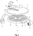
- the figure 3 which is a non-functional exploded view of the device 1, the latter comprises a handle 11 fixed to a support 12 for a cable 13.
- the support 12 has a substantially disc flat shape.
- the support 12 comprises on one of its faces (called “front face” thereafter), a groove 121 in the form of an Archimedes spiral (subsequently called “flat spiral”), the groove 121 being able to accommodate the cable 13 in a storage configuration.
- An orifice 124 is drilled through the support 12 at the end of the groove 121 located closest to the center of the spiral, the cable 13 passing through the support 12 through this orifice 124.
- the support 12 further comprises on its other face (hereinafter called “rear face”) clipping fingers 122 arranged near its entire periphery, the clipping fingers 122 receiving the cable 13 so that it does not can't slide there.
- the device 1 also includes a cover 17 of substantially disc shape making it possible to close the disc support 12 on its front face carrying the groove 121, so that the support 12 and its cover 17 share the same axis of symmetry A. It should be noted that the axis A is also the axis of the flat spiral formed by the groove 121.
- the cover 17 is made of a translucent material leaving visible the part of the cable 13 inserted in the groove 121.
- the cover 17 has in its center a disc opening 172, which is complementary to a cylindrical pivot 123 disposed in the center of the support 12, the pivot 123 being fitted into the opening 172 so that the cover 17 is able to pivot around the pivot 123.
- the cover 17 further comprises an opening 171 of rectangular shape, two opposite edges 1711 and 1712 of which are oriented substantially along the same vector R radia l to the disc cover 17 and to the flat spiral formed by the groove 121. These two edges 1711 and 1712 are capable of guiding slides 161 and 162 of a cursor 16.
- This cursor 16 also includes a spherical gripping pin 164.
- a plug male 14 equipped with a protective cover in the present example
- a male plug 15 for connection to an electric vehicle and to a charging terminal respectively.
- the figure 4a shows, in the storage configuration, the cable 13 received over substantially its entire length in the groove 121 in the form of a spiral hollowed out in the support 12.
- the groove 121 has a semi-disc shaped section of diameter substantially identical to the outside diameter of the cable 13, so that the cable 13 is received in the groove 121 over half of its section.
- the cable 13 crosses the cursor 16 by a conduit 163 of substantially disc section arranged specially for this purpose through the cursor 16.
- the diameter of the conduit 163 must allow the cable 13 to slide there without restraint.
- the cursor 16 forces the cable 13 to be extracted from the groove 121 over its entire length, this under the combined action of the cable 13 which slides in the duct 163 and slides 161 and 162 which slide along the edges 1711 and 1712 respectively, approaching the axis A of the spiral.
- the length of cable 13 extracted from the groove 121 it is easy to limit or even prevent the cable 13 from lying on the ground, and therefore avoid getting your hands dirty. In all cases, even if it drags on the ground, it will not be necessary to touch the cable 13 when putting it away after charging, it will then suffice to actuate the cursor 16 in the other direction of rotation, as explained below.
- the cursor 16 forces the cable 13 to be inserted into the groove 121 over its entire length, this always under the combined action of the cable 13 which slides in the duct 163 and the slides 161 and 162 which slide along the edges 1711 and 1712 respectively, but this time away from the axis A of the spiral.
- the device 1 according to the invention can very easily be placed in the boot of a vehicle.
- the device according to the invention also has the advantage of being very light and simple in design, therefore reliable and inexpensive.
- all of its elements can be made of plastic materials (except the conductive elements of the cable, of course).
- the device according to the invention makes it possible to unwind the cable to the desired length, and thus to prevent the cable from dragging on the ground between the vehicle and the load socket.
- It is also ergonomic thanks to its handle, in the sense that its use does not require getting your hands dirty and where it offers a limited space: it can be easily stored in the trunk of a vehicle without penalizing the useful volume for luggage.
- the cable is relatively well ventilated over its entire length and can thus cool by simple natural convection.
- the support and the cover can be easily perforated, in order to optimize the cooling by natural convection of the cable.
Landscapes
- Engineering & Computer Science (AREA)
- Power Engineering (AREA)
- Transportation (AREA)
- Mechanical Engineering (AREA)
- Electric Propulsion And Braking For Vehicles (AREA)
Description
- La présente invention concerne un dispositif portatif de dévidage d'un câble électrique, notamment un câble de charge pour un véhicule électrique ou hybride.
- Dans le contexte actuel de consensus autour du réchauffement climatique, la diminution des émissions de dioxyde de carbone (CO2) est un défi majeur auquel sont confrontés les constructeurs automobiles, les normes étant toujours plus exigeantes en la matière.
- Outre l'amélioration constante des rendements des moteurs thermiques classiques, qui s'accompagne d'une baisse des émissions de CO2, les véhicules électriques (« EV » d'après la terminologie anglo-saxonne « Electric Vehicle ») et les véhicules hybrides thermique-électrique (« HEV » d'après la terminologie anglo-saxonne « Hybrid Electric Vehicle ») sont aujourd'hui considérés comme la solution la plus prometteuse pour diminuer les émissions de CO2.
- Différentes technologies de stockage de l'énergie électrique ont été testées dans les dernières années afin de répondre aux besoins des EV. Il apparaît aujourd'hui que les batteries à cellules lithium-ion (Li-ion) sont celles susceptibles de fournir le meilleur compromis entre la densité de puissance, qui favorise les performances en termes d'accélération notamment, et la densité d'énergie, qui favorise l'autonomie. Cependant, l'utilisation de cette technologie Li-ion pour constituer des batteries de traction pour EV n'est pas sans poser de nombreuses difficultés, notamment si l'on considère les niveaux de tension nécessaires aux bornes de la batterie, de l'ordre de 400 volts (V), ou encore les niveaux de puissance de recharge nécessaires, de l'ordre de 2 à 3 kilowatts-heure en charge lente pendant plusieurs heures, jusqu'à plusieurs dizaines de kilowatts-heure en charge rapide pendant quelques dizaines de minutes. A de tels niveaux de puissance de charge, le câble de charge lui-même est soumis à de fortes contraintes.
- La solution la plus connue, qui est également la plus simple, est de fournir un câble de charge « volant » de section large adaptée à la puissance de charge maximale envisagée, que l'on transporte dans le coffre du véhicule. Le principal inconvénient de cette solution est que, durant les phases de charge, le câble traine par terre et se salit. Donc, soit l'utilisateur le replie proprement (ce qui peut s'avérer compliqué compte-tenu de sa section importante) avant de le ranger dans son coffre et il se salit les mains, soit il le pose en vrac dans le coffre et il y a un risque non négligeable qu'il doive le démêler lorsqu'il en aura à nouveau besoin. Se salir les mains semble donc inévitable, et il s'agit là d'un inconvénient que la présente invention se propose de résoudre.
- Pour éviter cet inconvénient, il est connu de l'état de la technique, notamment de la demande de brevet
US2015/0008878A1 , un dispositif de stockage d'un câble de charge comportant un dévidoir muni d'une manivelle pour dérouler et enrouler le câble, ainsi que d'une poignée pour transporter le dispositif. Il comporte également un boîtier de contrôle de la charge, intégré au centre du dévidoir, qui permet de piloter une charge lente sur prise standard. Un inconvénient majeur de cette solution est le risque d'échauffement. En effet, à des niveaux de puissance élevés pour charge rapide, les problèmes d'échauffement ne se limitent pas à la batterie : tous les éléments conducteurs impliqués dégagent une grande quantité de chaleur par effet joule et il est nécessaire de prendre en compte ce phénomène lors de la conception de l'ensemble de l'architecture électrique du véhicule. Ainsi, non seulement le câble de charge reliant le véhicule à la borne de charge doit être choisi de section suffisamment importante, mais il doit également être agencé d'une manière permettant d'évacuer la chaleur de manière contrôlée. Ce n'est manifestement pas le cas d'une solution par enroulement comme dansUS2015/0008878A1 , où le câble est non seulement enroulé de manière serrée, mais en plus il est enfermé, ce qui empêche tout phénomène de refroidissement par convexion. - Le document
US 4 150 798 A divulgue un dispositif portatif de dévidage d'un câble électrique, comprenant un support et un couvercle enfermant, en collaboration avec le support, la partie du câble accueillie dans le sillon, le couvercle comportant une ouverture. En outre, le documentDE 85 26 244 U1 divulgue un curseur qui est apte à se déplacer selon une direction axiale, le curseur comportant des moyens de guidage du câble. En outre, le documentUS 2014/034382 A1 divulgue un câble électrique pour fournir de l'énergie à un véhicule, avec une gaine de câble, à l'intérieur de laquelle sont prévus au moins deux conducteurs électriques, qui sont connectés à au moins un connecteur se trouvant à une extrémité du câble. La gaine de câble est conçue de manière à ce que le câble soit tenu avec une force de rappel dans une position de repos, dans laquelle le câble forme une spirale et est orienté le long d'une surface plane ou courbée. De plus, le documentUS 2013/099042 A1 divulgue un dispositif comportant une première pluralité de rouleaux disposés selon un motif hélicoïdal gauche, une deuxième pluralité de rouleaux en dessous de la première pluralité de rouleaux et agencés selon un motif hélicoïdal droit, une troisième pluralité de rouleaux disposés dans une configuration en S, un guide configuré pour se déplacer verticalement, le guide étant agencé sur un premier côté de la première pluralité de rouleaux, et une pince configurée pour se déplacer verticalement, la troisième pluralité de rouleaux étant disposée entre la première et la deuxième pluralité de rouleaux, et la pince étant disposée sur un second côté de la première pluralité de rouleaux. - L'invention a notamment pour but de surmonter les inconvénients précités, notamment ceux liés aux salissures et au risque d'échauffement. A cet effet, l'invention a pour objet un dispositif portatif de dévidage d'un câble électrique comportant un élément de connexion à chacune de ses extrémités. Le dispositif comporte un support dans lequel est creusé un sillon formant une spirale plate, le sillon étant apte à accueillir au moins partiellement le câble. Il comporte également un couvercle enfermant, en collaboration avec le support, la partie du câble accueillie dans le sillon. Le couvercle comporte une ouverture dans laquelle est apte à se déplacer un curseur selon une direction radiale à la spirale. Le curseur comporte des moyens de guidage du câble au travers de l'ouverture. Le support, le couvercle et le curseur sont agencés de telle sorte que la mise en rotation du couvercle et du curseur par rapport au support autour de l'axe de la spirale entraîne, dans un sens de rotation, le déplacement du curseur dans la direction opposée à l'axe de la spirale, ledit déplacement provoquant l'insertion, par les moyens de guidage au travers de l'ouverture, du câble dans le sillon sous le couvercle. Ils sont également agencés de telle sorte que la mise en rotation du couvercle et du curseur par rapport au support autour de l'axe de la spirale entraîne, dans l'autre sens de rotation, le déplacement du curseur dans la direction de l'axe de la spirale, ledit déplacement provoquant l'extraction, par les moyens de guidage au travers de l'ouverture, du câble hors du sillon et au-dessus du couvercle.
- Avantageusement, l'ouverture peut comporter deux bords parallèles à la direction radiale à la spirale et le curseur peut comporter deux glissières aptes à coulisser le long des deux bords respectivement.
- Avantageusement, le dispositif peut comporter une poignée solidaire du support et le curseur peut comporter un téton de préhension, de sorte que le couvercle et le curseur soient aptes à être mis en rotation par l'intermédiaire du téton, en retenant simultanément le support par l'intermédiaire de la poignée.
- Par exemple, les moyens de guidage du câble au travers de l'ouverture peuvent inclure un conduit de section sensiblement discale.
- Par exemple, le support pouvant avoir au moins deux faces dont l'une porte le sillon, un orifice peut être percé dans le support à proximité de l'extrémité du sillon située au plus près du centre de la spirale, le câble pouvant passer au travers de l'orifice d'une face à l'autre du support.
- Par exemple, le support peut comporter, sur sa face ne portant pas le sillon, au moins un élément de clipsage pour y bloquer le câble (13).
- Avantageusement, le support peut comporter un pivot cylindrique ayant pour axe l'axe de la spirale, et le couvercle peut comporter une ouverture discale ayant également pour axe l'axe de la spirale, le pivot pouvant être emboîté dans l'ouverture discale, de telle sorte que le couvercle et le curseur soient aptes à être mis en rotation par rapport au support autour de l'axe de la spirale.
- Par exemple, le support et le couvercle peuvent avoir une forme sensiblement discale. Le support (12) et le couvercle (17) peuvent alors avoir sensiblement le même diamètre.
- La présente invention a également pour objet un tel dispositif portatif de dévidage d'un câble électrique pour charger un véhicule électrique ou hybride.
- Outre de limiter les salissures et de faciliter le refroidissement du câble, le dispositif selon l'invention a pour principal avantage son ergonomie en termes de poids et d'encombrement.
- D'autres caractéristiques et avantages de l'invention apparaîtront à l'aide de la description qui suit faite en regard de dessins annexés 1, 2, 3, et 5, qui illustrent des vues schématiques d'ensemble, et des dessins annexés 4a, 4b et 4c, qui illustrent des vues schématiques en coupe, d'un même mode de réalisation avantageux de l'invention. Les éléments identiques illustrés sur ces figures partagent les mêmes références. Toutefois, pour des raisons de clarté, toutes les références n'ont pas été reportées sur toutes les figures.
- Les figures illustrent un même dispositif 1 selon l'invention pour recharger un véhicule électrique ou hybride. Les
figures 1 et 2 illustrent, selon deux points de vue opposés, ce dispositif 1 dans une configuration de rangement. Lafigure 5 illustre de dispositif 1 dans une configuration d'utilisation. Comme bien illustré par lafigure 3 , qui est une vue non-fonctionnelle en éclaté du dispositif 1, celui-ci comporte une poignée 11 fixée à un support 12 pour un câble 13. Dans le présent exemple de réalisation, le support 12 présente une forme plate sensiblement discale. Comme bien illustré à lafigure 4a , le support 12 comporte sur l'une de ses faces (appelée « face avant » par la suite), un sillon 121 en forme de spirale d'Archimède (appelée « spirale plate » par la suite), le sillon 121 pouvant accueillir le câble 13 dans une configuration de rangement. Un orifice 124 est percé au travers du support 12 à l'extrémité du sillon 121 située au plus près du centre de la spirale, le câble 13 traversant le support 12 par cet orifice 124. Comme bien illustré à lafigure 2 , le support 12 comporte en outre sur son autre face (appelée « face arrière » par la suite) des doigts de clipsage 122 disposés à proximité de toute sa périphérie, les doigts de clipsage 122 accueillant le câble 13 de telle sorte qu'il ne puisse pas y coulisser. Le dispositif 1 comporte également un couvercle 17 de forme sensiblement discale permettant de fermer le support discal 12 sur sa face avant portant le sillon 121, de sorte que le support 12 et son couvercle 17 partagent un même axe de symétrie A. Il faut noter que l'axe A est également l'axe de la spirale plate formée par le sillon 121. Dans le présent exemple de réalisation, le couvercle 17 est fait d'un matériau translucide laissant visible la partie du câble 13 insérée dans le sillon 121. Dans le présent exemple de réalisation, le couvercle 17 comporte en son centre une ouverture discale 172, qui est complémentaire d'un pivot cylindrique 123 disposé au centre du support 12, le pivot 123 étant emboîté dans l'ouverture 172 de telle sorte que le couvercle 17 est apte à pivoter autour du pivot 123. Le couvercle 17 comporte en outre une ouverture 171 de forme rectangulaire dont deux bords opposés 1711 et 1712 sont orientés sensiblement selon un même vecteur R radial au couvercle discal 17 et à la spirale plate formée par le sillon 121. Ces deux bords 1711 et 1712 sont aptes à guider des glissières 161 et 162 d'un curseur 16. Ce curseur 16 comporte par ailleurs un téton sphérique de préhension 164. Aux deux extrémités du câble 13 sont disposées une fiche mâle 14 (équipée d'un capot de protection dans le présent exemple) et une fiche mâle 15 pour connexion à un véhicule électrique et à une borne de charge respectivement. - La
figure 4a montre, dans la configuration de rangement, le câble 13 accueilli sur sensiblement toute sa longueur dans le sillon 121 en forme de spirale creusé dans le support 12. Le sillon 121 présente une section de forme semi-discale de diamètre sensiblement identique au diamètre extérieur du câble 13, de sorte que le câble 13 soit accueilli dans le sillon 121 sur la moitié de sa section. Comme mieux illustré par les vues en coupe desfigures 4a, 4b et 4c , le câble 13 traverse le curseur 16 par un conduit 163 de section sensiblement discale aménagé spécialement à cet effet au travers du curseur 16. Le diamètre du conduit 163 doit permettre au câble 13 d'y coulisser sans retenue. - Ainsi, en prenant à pleine main la poignée 11, il suffit d'entraîner le téton 164 du curseur 16 dans un mouvement de rotation autour de l'axe A de la spirale, en pinçant le téton 164 entre le pouce et l'index de l'autre main.
- Dans un sens de rotation, en vue de raccorder le véhicule à une borne de charge (configuration dite « de charge » illustrée par la
figure 5 ), le curseur 16 force l'extraction du câble 13 hors du sillon 121 sur toute sa longueur, ceci sous l'action conjuguée du câble 13 qui coulisse dans le conduit 163 et des glissières 161 et 162 qui coulissent le long des bords 1711 et 1712 respectivement, en se rapprochant de l'axe A de la spirale. En adaptant la longueur de câble 13 extraite du sillon 121, on peut aisément limiter voire empêcher le câble 13 de traîner par terre, et donc éviter de se salir les mains. En tous les cas, même s'il traine par terre, il ne sera pas nécessaire de toucher le câble 13 au moment de le ranger après la charge, il suffira alors d'actionner le curseur 16 dans l'autre sens de rotation, comme explicité ci-après. - Dans l'autre sens de rotation, en vue de ranger le dispositif 1 dans le coffre du véhicule par exemple (configuration dite « de rangement » illustrée par la
figure 1 ), le curseur 16 force l'insertion du câble 13 dans du sillon 121 sur toute sa longueur, ceci toujours sous l'action conjuguée du câble 13 qui coulisse dans le conduit 163 et des glissières 161 et 162 qui coulissent le long des bords 1711 et 1712 respectivement, mais cette fois en s'éloignant de l'axe A de la spirale. Dans cette configuration de rangement, le dispositif 1 selon l'invention peut très facilement être déposé dans le coffre d'un véhicule. - L'exemple de réalisation ci-dessus n'est donné qu'à titre d'illustration, l'invention étant applicable à tout appareil électrique nécessitant d'être branché périodiquement à une prise de courant.
- Le dispositif selon l'invention a encore pour avantage d'être très léger et simple de conception, donc fiable et peu coûteux. En particulier, tous ses éléments peuvent être faits de matériaux plastiques (sauf les éléments conducteurs du câble, bien-sûr). Avantageusement, le dispositif selon l'invention permet de dérouler le câble à la longueur voulue, et ainsi d'empêcher le câble de trainer par terre entre le véhicule et la prise de charge. Il est également ergonomique grâce à sa poignée, dans le sens où son utilisation ne nécessite pas de se salir les mains et où il offre un encombrement limité : on peut le ranger facilement dans le coffre d'un véhicule sans pénaliser le volume utile pour les bagages. Enfin, le câble est relativement bien aéré sur toute sa longueur et peut ainsi refroidir par simple convexion naturelle. De plus, le support et le couvercle peuvent être aisément ajourés, afin d'optimiser le refroidissement par convexion naturelle du câble.
Claims (10)
- Dispositif (1) portatif de dévidage d'un câble électrique (13) comportant un élément de connexion (14, 15) à chacune de ses extrémités, le dispositif comprenant :- un support (12) dans lequel est creusé un sillon (121) formant une spirale plate, le sillon étant apte à accueillir au moins partiellement le câble, et ;- un couvercle (17) enfermant, en collaboration avec le support, la partie du câble accueillie dans le sillon, le couvercle comportant une ouverture (171) dans laquelle est apte à se déplacer un curseur (16) selon une direction (R) radiale à la spirale, le curseur comportant des moyens de guidage du câble au travers de l'ouverture ;le support, le couvercle et le curseur étant agencés de telle sorte que la mise en rotation du couvercle et du curseur par rapport au support autour de l'axe (A) de la spirale entraîne :- dans un sens de rotation, le déplacement du curseur dans la direction opposée à l'axe de la spirale, ledit déplacement provoquant l'insertion, par les moyens de guidage au travers de l'ouverture, du câble dans le sillon sous le couvercle ;- dans l'autre sens de rotation, le déplacement du curseur dans la direction de l'axe de la spirale, ledit déplacement provoquant l'extraction, par les moyens de guidage au travers de l'ouverture, du câble hors du sillon et au-dessus du couvercle.
- Dispositif selon la revendication 1, caractérisé en ce que :- l'ouverture (171) comporte deux bords (1711, 1712) parallèles à la direction (R) radiale à la spirale ;- le curseur (16) comporte deux glissières (161, 162) aptes à coulisser le long desdits deux bords respectivement.
- Dispositif selon la revendication 1, caractérisé en ce que :- il comporte une poignée (11) solidaire du support (12) ;- le curseur (16) comporte un téton de préhension (164) ;
de sorte que le couvercle et le curseur sont aptes à être mis en rotation par l'intermédiaire du téton, en retenant simultanément le support par l'intermédiaire de la poignée. - Dispositif selon la revendication 1, caractérisé en ce que les moyens de guidage du câble (13) au travers de l'ouverture (171) incluent un conduit (163) de section sensiblement discale.
- Dispositif selon la revendication 1, caractérisé en ce que, le support (12) ayant au moins deux faces dont l'une porte le sillon (121), un orifice (124) est percé dans le support à proximité de l'extrémité du sillon située au plus près du centre de la spirale, le câble (13) passant au travers de l'orifice d'une face à l'autre du support.
- Dispositif selon la revendication 5, caractérisé en ce que le support (12) comporte, sur sa face ne portant pas le sillon (121), au moins un élément de clipsage (122) pour y bloquer le câble (13).
- Dispositif selon la revendication 1, caractérisé en ce que :- le support (12) comporte un pivot cylindrique (123) ayant pour axe l'axe (A) de la spirale, et ;- le couvercle (17) comporte une ouverture discale (172) ayant également pour axe l'axe de la spirale ;
le pivot étant emboîté dans l'ouverture discale, de telle sorte que le couvercle et le curseur (16) sont aptes à être mis en rotation par rapport au support autour de l'axe de la spirale. - Dispositif selon la revendication 1, caractérisé en ce que le support (12) et le couvercle (17) ont une forme sensiblement discale.
- Dispositif selon la revendication 8, caractérisé en ce que le support (12) et le couvercle (17) ont sensiblement le même diamètre.
- Dispositif (1) portatif de dévidage d'un câble électrique (13) de charge d'un véhicule électrique ou hybride selon l'une quelconque des revendications précédentes.
Applications Claiming Priority (2)
| Application Number | Priority Date | Filing Date | Title |
|---|---|---|---|
| FR1655562A FR3052925B1 (fr) | 2016-06-15 | 2016-06-15 | Dispositif portatif de devidage d'un cable electrique, notamment un cable de charge pour un vehicule electrique ou hybride |
| PCT/FR2017/051477 WO2017216454A1 (fr) | 2016-06-15 | 2017-06-09 | Dispositif portatif de devidage d'un cable electrique, notamment un cable de charge pour un vehicule electrique ou hybride |
Publications (2)
| Publication Number | Publication Date |
|---|---|
| EP3472919A1 EP3472919A1 (fr) | 2019-04-24 |
| EP3472919B1 true EP3472919B1 (fr) | 2020-03-25 |
Family
ID=56990550
Family Applications (1)
| Application Number | Title | Priority Date | Filing Date |
|---|---|---|---|
| EP17734793.7A Active EP3472919B1 (fr) | 2016-06-15 | 2017-06-09 | Dispositif portatif de dévidage d'un câble électrique, notamment un câble de charge pour un véhicule électrique ou hybride |
Country Status (4)
| Country | Link |
|---|---|
| EP (1) | EP3472919B1 (fr) |
| CN (1) | CN109476440B (fr) |
| FR (1) | FR3052925B1 (fr) |
| WO (1) | WO2017216454A1 (fr) |
Cited By (2)
| Publication number | Priority date | Publication date | Assignee | Title |
|---|---|---|---|---|
| AT526057A4 (de) * | 2022-07-24 | 2023-11-15 | Reelectriq Gmbh | Kontrollvorrichtung für eine Kontrolle eines Auszugs eines elektrischen Verbindungskabels von einer Kabelrolle |
| FR3138887A1 (fr) * | 2022-08-18 | 2024-02-23 | Psa Automobiles Sa | Vehicule automobile avec câble de recharge d’une batterie de traction autour d’un tambour rotatif |
Families Citing this family (11)
| Publication number | Priority date | Publication date | Assignee | Title |
|---|---|---|---|---|
| DE102018131934A1 (de) | 2018-12-12 | 2020-07-02 | Volkswagen Aktiengesellschaft | Kabelaufrollvorrichtung für ein elektrisches Kraftfahrzeug-Ladekabel sowie Anordnung eines Kraftfahrzeug-Ladekabels an einer solchen Kabelaufrollvorrichtung |
| FR3090609B1 (fr) | 2018-12-21 | 2021-07-16 | Renault Sas | Devidoir pour cable compactable |
| IT201900016175A1 (it) * | 2019-09-12 | 2019-12-12 | Zeca S P A | Avvolgicavo per la ricarica di veicoli elettrici |
| IT202000016447A1 (it) * | 2020-07-07 | 2020-10-07 | Zeca S P A | Avvolgicavo per la ricarica di veicoli elettrici |
| CN112389239B (zh) * | 2020-12-01 | 2022-12-27 | 安徽艾伊德动力科技有限公司 | 一种汽车充电装置 |
| DE102020132471B3 (de) | 2020-12-07 | 2022-05-25 | Günther Doppler | Aufwickeleinheit für ein Kabel |
| CN112660222A (zh) * | 2020-12-14 | 2021-04-16 | 中车大同电力机车有限公司 | 电缆运输装置 |
| DE102021132045A1 (de) | 2021-12-06 | 2023-06-07 | Ford Global Technologies Llc | Vorrichtung zum Auf- und Abwickeln eines langestreckten, flexiblen Elementes |
| IT202100031841A1 (it) * | 2021-12-20 | 2023-06-20 | Rmg Ind Advance S R L | Valigetta portacavo per autoveicoli a trazione elettrica |
| DE102022109465B3 (de) | 2022-04-19 | 2023-05-11 | Günther Doppler | Aufwickeleinheit für ein kabel |
| CN116853030B (zh) * | 2023-07-24 | 2026-01-27 | 中国电建集团江西省水电工程局有限公司 | 一种用于新能源汽车的充电装置 |
Family Cites Families (14)
| Publication number | Priority date | Publication date | Assignee | Title |
|---|---|---|---|---|
| JPS5524289Y2 (fr) * | 1974-11-06 | 1980-06-10 | ||
| US4150798A (en) * | 1977-08-10 | 1979-04-24 | Aragon Manuel Y | Cord and line storage reel |
| DE8526244U1 (de) * | 1985-09-13 | 1985-11-14 | Denk, Hartmut, 8441 Aiterhofen | Kabeltrommel |
| US6805314B2 (en) * | 2001-03-27 | 2004-10-19 | Michael B. Hopper | Tool support |
| US20050284980A1 (en) * | 2004-06-02 | 2005-12-29 | Chi-Lin Chang | Cable winding apparatus for charger |
| TWI317723B (en) * | 2006-10-27 | 2009-12-01 | Asustek Comp Inc | Cable retractor and electronic device using the same |
| EP2506378A1 (fr) * | 2011-04-01 | 2012-10-03 | Lapp Engineering & Co. | Ligne électrique pour l'alimentation en énergie de véhicules |
| US8763944B2 (en) * | 2011-10-19 | 2014-07-01 | Ge-Hitachi Nuclear Energy Americas, Llc | Slip hub take-up reel without slip ring |
| JP2013162550A (ja) | 2012-02-01 | 2013-08-19 | Chuo Spring Co Ltd | 充電ケーブル用収容装置 |
| CN202924490U (zh) * | 2012-12-02 | 2013-05-08 | 威海广泰空港设备股份有限公司 | 电缆卷动引导装置 |
| JP6493659B2 (ja) * | 2014-11-19 | 2019-04-03 | 三菱自動車工業株式会社 | 充電口構造 |
| US9346653B1 (en) * | 2014-11-20 | 2016-05-24 | Shenzhen Mindray Bio-Medical Electronics Co., Ltd. | Cord retractor |
| CN204280901U (zh) * | 2014-11-24 | 2015-04-22 | 胡平金 | 一种线缆及其端部器件的收纳装置 |
| CN204910394U (zh) * | 2015-08-25 | 2015-12-30 | 赵庆霞 | 吸氧器氧气管收纳放置装置 |
-
2016
- 2016-06-15 FR FR1655562A patent/FR3052925B1/fr not_active Expired - Fee Related
-
2017
- 2017-06-09 WO PCT/FR2017/051477 patent/WO2017216454A1/fr not_active Ceased
- 2017-06-09 CN CN201780037196.3A patent/CN109476440B/zh active Active
- 2017-06-09 EP EP17734793.7A patent/EP3472919B1/fr active Active
Non-Patent Citations (1)
| Title |
|---|
| None * |
Cited By (3)
| Publication number | Priority date | Publication date | Assignee | Title |
|---|---|---|---|---|
| AT526057A4 (de) * | 2022-07-24 | 2023-11-15 | Reelectriq Gmbh | Kontrollvorrichtung für eine Kontrolle eines Auszugs eines elektrischen Verbindungskabels von einer Kabelrolle |
| AT526057B1 (de) * | 2022-07-24 | 2023-11-15 | Reelectriq Gmbh | Kontrollvorrichtung für eine Kontrolle eines Auszugs eines elektrischen Verbindungskabels von einer Kabelrolle |
| FR3138887A1 (fr) * | 2022-08-18 | 2024-02-23 | Psa Automobiles Sa | Vehicule automobile avec câble de recharge d’une batterie de traction autour d’un tambour rotatif |
Also Published As
| Publication number | Publication date |
|---|---|
| FR3052925B1 (fr) | 2018-08-17 |
| FR3052925A1 (fr) | 2017-12-22 |
| CN109476440B (zh) | 2020-07-24 |
| CN109476440A (zh) | 2019-03-15 |
| EP3472919A1 (fr) | 2019-04-24 |
| WO2017216454A1 (fr) | 2017-12-21 |
Similar Documents
| Publication | Publication Date | Title |
|---|---|---|
| WO2017216454A1 (fr) | Dispositif portatif de devidage d'un cable electrique, notamment un cable de charge pour un vehicule electrique ou hybride | |
| EP3463985B1 (fr) | Dispositif portatif de dévidage d'un câble électrique, notamment un câble de charge pour un véhicule électrique ou hybride | |
| FR3033953A1 (fr) | Rangement pour cable electrique | |
| EP3271983B1 (fr) | Devidoir pour cable electrique | |
| FR2964805A1 (fr) | Dispositif d'enroulement d'un cable electrique destine a alimenter un vehicule electrique | |
| WO2017046545A1 (fr) | Dispositif dévidoir de cable ou tuyau | |
| FR2990049A3 (fr) | Cable de charge de vehicule electrique | |
| EP3312046B1 (fr) | Dispositif de dévidage d'un câble électrique, notamment un câble de charge pour un véhicule électrique ou hybride | |
| FR3018747A3 (fr) | Dispositf de rangement d'un cable de charge pour un vehicule electrique ou hybride | |
| EP0692849A1 (fr) | Elément mobile de connexion électrique muni d'un câble liaison et d'une poignée de préhension | |
| EP2710445B1 (fr) | Etui de protection pour une console de jeux | |
| FR3050192A1 (fr) | Dispositif portatif de devidage d’un cable electrique, notamment un cable de charge pour un vehicule electrique ou hybride | |
| FR2967527A1 (fr) | Potence de support d'un cable electrique notamment d'une borne de charge de vehicule electrique | |
| EP4410654B1 (fr) | Unité d'alimentation électrique embarquée pour cycle | |
| FR2989899A1 (fr) | Base pour chariot de golf et chariot de golf | |
| FR3090609A1 (fr) | Devidoir pour cable compactable | |
| EP2461446B1 (fr) | Dispositif d'enroulement pour fil électrique | |
| FR3142952A1 (fr) | Vehicule electrique comportant une connexion electrique pour la recharge. | |
| WO2024089323A1 (fr) | Systeme de recharge pour un vehicule electrifie comportant un cable deployable et un logement de rangement muni d'un joint a depression | |
| FR3052572B1 (fr) | Dispositif d'alimentation electrique d'appareils electroniques et/ou electriques et sac integrant un tel dispositif | |
| FR2920604A1 (fr) | Etui pour un appareil electrique portable | |
| FR3098807A1 (fr) | Accessoire pour le portage et la manipulation d’un câble de charge d’une batterie de véhicule automobile | |
| FR3068578B1 (fr) | Baton de randonnee comprenant un dispositif de creation de courant electrique | |
| FR3023150A1 (fr) | Dispositif range-accessoire pour adaptateur secteur et cordon electrique avec au moins un connecteur | |
| FR2768887A1 (fr) | Compartiment a piles pour un telephone mobile |
Legal Events
| Date | Code | Title | Description |
|---|---|---|---|
| STAA | Information on the status of an ep patent application or granted ep patent |
Free format text: STATUS: UNKNOWN |
|
| STAA | Information on the status of an ep patent application or granted ep patent |
Free format text: STATUS: THE INTERNATIONAL PUBLICATION HAS BEEN MADE |
|
| PUAI | Public reference made under article 153(3) epc to a published international application that has entered the european phase |
Free format text: ORIGINAL CODE: 0009012 |
|
| STAA | Information on the status of an ep patent application or granted ep patent |
Free format text: STATUS: REQUEST FOR EXAMINATION WAS MADE |
|
| 17P | Request for examination filed |
Effective date: 20181213 |
|
| AK | Designated contracting states |
Kind code of ref document: A1 Designated state(s): AL AT BE BG CH CY CZ DE DK EE ES FI FR GB GR HR HU IE IS IT LI LT LU LV MC MK MT NL NO PL PT RO RS SE SI SK SM TR |
|
| AX | Request for extension of the european patent |
Extension state: BA ME |
|
| REG | Reference to a national code |
Ref country code: DE Ref legal event code: R079 Ref document number: 602017013699 Country of ref document: DE Free format text: PREVIOUS MAIN CLASS: H02J0007000000 Ipc: B60L0053160000 |
|
| DAV | Request for validation of the european patent (deleted) | ||
| DAX | Request for extension of the european patent (deleted) | ||
| GRAP | Despatch of communication of intention to grant a patent |
Free format text: ORIGINAL CODE: EPIDOSNIGR1 |
|
| RIC1 | Information provided on ipc code assigned before grant |
Ipc: B65H 75/44 20060101ALI20190910BHEP Ipc: H02J 7/00 20060101ALI20190910BHEP Ipc: B65H 75/40 20060101ALI20190910BHEP Ipc: B65H 75/26 20060101ALI20190910BHEP Ipc: H02G 11/02 20060101ALI20190910BHEP Ipc: B60L 53/16 20190101AFI20190910BHEP |
|
| STAA | Information on the status of an ep patent application or granted ep patent |
Free format text: STATUS: GRANT OF PATENT IS INTENDED |
|
| INTG | Intention to grant announced |
Effective date: 20191017 |
|
| GRAS | Grant fee paid |
Free format text: ORIGINAL CODE: EPIDOSNIGR3 |
|
| GRAA | (expected) grant |
Free format text: ORIGINAL CODE: 0009210 |
|
| STAA | Information on the status of an ep patent application or granted ep patent |
Free format text: STATUS: THE PATENT HAS BEEN GRANTED |
|
| AK | Designated contracting states |
Kind code of ref document: B1 Designated state(s): AL AT BE BG CH CY CZ DE DK EE ES FI FR GB GR HR HU IE IS IT LI LT LU LV MC MK MT NL NO PL PT RO RS SE SI SK SM TR |
|
| REG | Reference to a national code |
Ref country code: GB Ref legal event code: FG4D Free format text: NOT ENGLISH |
|
| REG | Reference to a national code |
Ref country code: AT Ref legal event code: REF Ref document number: 1248192 Country of ref document: AT Kind code of ref document: T Effective date: 20200415 Ref country code: IE Ref legal event code: FG4D Free format text: LANGUAGE OF EP DOCUMENT: FRENCH |
|
| REG | Reference to a national code |
Ref country code: DE Ref legal event code: R096 Ref document number: 602017013699 Country of ref document: DE |
|
| PG25 | Lapsed in a contracting state [announced via postgrant information from national office to epo] |
Ref country code: RS Free format text: LAPSE BECAUSE OF FAILURE TO SUBMIT A TRANSLATION OF THE DESCRIPTION OR TO PAY THE FEE WITHIN THE PRESCRIBED TIME-LIMIT Effective date: 20200325 Ref country code: NO Free format text: LAPSE BECAUSE OF FAILURE TO SUBMIT A TRANSLATION OF THE DESCRIPTION OR TO PAY THE FEE WITHIN THE PRESCRIBED TIME-LIMIT Effective date: 20200625 Ref country code: FI Free format text: LAPSE BECAUSE OF FAILURE TO SUBMIT A TRANSLATION OF THE DESCRIPTION OR TO PAY THE FEE WITHIN THE PRESCRIBED TIME-LIMIT Effective date: 20200325 |
|
| PG25 | Lapsed in a contracting state [announced via postgrant information from national office to epo] |
Ref country code: HR Free format text: LAPSE BECAUSE OF FAILURE TO SUBMIT A TRANSLATION OF THE DESCRIPTION OR TO PAY THE FEE WITHIN THE PRESCRIBED TIME-LIMIT Effective date: 20200325 Ref country code: SE Free format text: LAPSE BECAUSE OF FAILURE TO SUBMIT A TRANSLATION OF THE DESCRIPTION OR TO PAY THE FEE WITHIN THE PRESCRIBED TIME-LIMIT Effective date: 20200325 Ref country code: LV Free format text: LAPSE BECAUSE OF FAILURE TO SUBMIT A TRANSLATION OF THE DESCRIPTION OR TO PAY THE FEE WITHIN THE PRESCRIBED TIME-LIMIT Effective date: 20200325 Ref country code: GR Free format text: LAPSE BECAUSE OF FAILURE TO SUBMIT A TRANSLATION OF THE DESCRIPTION OR TO PAY THE FEE WITHIN THE PRESCRIBED TIME-LIMIT Effective date: 20200626 Ref country code: BG Free format text: LAPSE BECAUSE OF FAILURE TO SUBMIT A TRANSLATION OF THE DESCRIPTION OR TO PAY THE FEE WITHIN THE PRESCRIBED TIME-LIMIT Effective date: 20200625 |
|
| REG | Reference to a national code |
Ref country code: NL Ref legal event code: MP Effective date: 20200325 |
|
| REG | Reference to a national code |
Ref country code: LT Ref legal event code: MG4D |
|
| PG25 | Lapsed in a contracting state [announced via postgrant information from national office to epo] |
Ref country code: NL Free format text: LAPSE BECAUSE OF FAILURE TO SUBMIT A TRANSLATION OF THE DESCRIPTION OR TO PAY THE FEE WITHIN THE PRESCRIBED TIME-LIMIT Effective date: 20200325 |
|
| PG25 | Lapsed in a contracting state [announced via postgrant information from national office to epo] |
Ref country code: EE Free format text: LAPSE BECAUSE OF FAILURE TO SUBMIT A TRANSLATION OF THE DESCRIPTION OR TO PAY THE FEE WITHIN THE PRESCRIBED TIME-LIMIT Effective date: 20200325 Ref country code: SM Free format text: LAPSE BECAUSE OF FAILURE TO SUBMIT A TRANSLATION OF THE DESCRIPTION OR TO PAY THE FEE WITHIN THE PRESCRIBED TIME-LIMIT Effective date: 20200325 Ref country code: SK Free format text: LAPSE BECAUSE OF FAILURE TO SUBMIT A TRANSLATION OF THE DESCRIPTION OR TO PAY THE FEE WITHIN THE PRESCRIBED TIME-LIMIT Effective date: 20200325 Ref country code: RO Free format text: LAPSE BECAUSE OF FAILURE TO SUBMIT A TRANSLATION OF THE DESCRIPTION OR TO PAY THE FEE WITHIN THE PRESCRIBED TIME-LIMIT Effective date: 20200325 Ref country code: CZ Free format text: LAPSE BECAUSE OF FAILURE TO SUBMIT A TRANSLATION OF THE DESCRIPTION OR TO PAY THE FEE WITHIN THE PRESCRIBED TIME-LIMIT Effective date: 20200325 Ref country code: LT Free format text: LAPSE BECAUSE OF FAILURE TO SUBMIT A TRANSLATION OF THE DESCRIPTION OR TO PAY THE FEE WITHIN THE PRESCRIBED TIME-LIMIT Effective date: 20200325 Ref country code: PT Free format text: LAPSE BECAUSE OF FAILURE TO SUBMIT A TRANSLATION OF THE DESCRIPTION OR TO PAY THE FEE WITHIN THE PRESCRIBED TIME-LIMIT Effective date: 20200818 Ref country code: IS Free format text: LAPSE BECAUSE OF FAILURE TO SUBMIT A TRANSLATION OF THE DESCRIPTION OR TO PAY THE FEE WITHIN THE PRESCRIBED TIME-LIMIT Effective date: 20200725 |
|
| REG | Reference to a national code |
Ref country code: AT Ref legal event code: MK05 Ref document number: 1248192 Country of ref document: AT Kind code of ref document: T Effective date: 20200325 |
|
| REG | Reference to a national code |
Ref country code: DE Ref legal event code: R097 Ref document number: 602017013699 Country of ref document: DE |
|
| PG25 | Lapsed in a contracting state [announced via postgrant information from national office to epo] |
Ref country code: MC Free format text: LAPSE BECAUSE OF FAILURE TO SUBMIT A TRANSLATION OF THE DESCRIPTION OR TO PAY THE FEE WITHIN THE PRESCRIBED TIME-LIMIT Effective date: 20200325 Ref country code: ES Free format text: LAPSE BECAUSE OF FAILURE TO SUBMIT A TRANSLATION OF THE DESCRIPTION OR TO PAY THE FEE WITHIN THE PRESCRIBED TIME-LIMIT Effective date: 20200325 Ref country code: AT Free format text: LAPSE BECAUSE OF FAILURE TO SUBMIT A TRANSLATION OF THE DESCRIPTION OR TO PAY THE FEE WITHIN THE PRESCRIBED TIME-LIMIT Effective date: 20200325 Ref country code: DK Free format text: LAPSE BECAUSE OF FAILURE TO SUBMIT A TRANSLATION OF THE DESCRIPTION OR TO PAY THE FEE WITHIN THE PRESCRIBED TIME-LIMIT Effective date: 20200325 Ref country code: IT Free format text: LAPSE BECAUSE OF FAILURE TO SUBMIT A TRANSLATION OF THE DESCRIPTION OR TO PAY THE FEE WITHIN THE PRESCRIBED TIME-LIMIT Effective date: 20200325 |
|
| REG | Reference to a national code |
Ref country code: CH Ref legal event code: PL |
|
| PLBE | No opposition filed within time limit |
Free format text: ORIGINAL CODE: 0009261 |
|
| STAA | Information on the status of an ep patent application or granted ep patent |
Free format text: STATUS: NO OPPOSITION FILED WITHIN TIME LIMIT |
|
| PG25 | Lapsed in a contracting state [announced via postgrant information from national office to epo] |
Ref country code: PL Free format text: LAPSE BECAUSE OF FAILURE TO SUBMIT A TRANSLATION OF THE DESCRIPTION OR TO PAY THE FEE WITHIN THE PRESCRIBED TIME-LIMIT Effective date: 20200325 |
|
| 26N | No opposition filed |
Effective date: 20210112 |
|
| PG25 | Lapsed in a contracting state [announced via postgrant information from national office to epo] |
Ref country code: LU Free format text: LAPSE BECAUSE OF NON-PAYMENT OF DUE FEES Effective date: 20200609 |
|
| REG | Reference to a national code |
Ref country code: BE Ref legal event code: MM Effective date: 20200630 |
|
| PG25 | Lapsed in a contracting state [announced via postgrant information from national office to epo] |
Ref country code: CH Free format text: LAPSE BECAUSE OF NON-PAYMENT OF DUE FEES Effective date: 20200630 Ref country code: LI Free format text: LAPSE BECAUSE OF NON-PAYMENT OF DUE FEES Effective date: 20200630 Ref country code: IE Free format text: LAPSE BECAUSE OF NON-PAYMENT OF DUE FEES Effective date: 20200609 |
|
| PG25 | Lapsed in a contracting state [announced via postgrant information from national office to epo] |
Ref country code: BE Free format text: LAPSE BECAUSE OF NON-PAYMENT OF DUE FEES Effective date: 20200630 Ref country code: SI Free format text: LAPSE BECAUSE OF FAILURE TO SUBMIT A TRANSLATION OF THE DESCRIPTION OR TO PAY THE FEE WITHIN THE PRESCRIBED TIME-LIMIT Effective date: 20200325 |
|
| PG25 | Lapsed in a contracting state [announced via postgrant information from national office to epo] |
Ref country code: TR Free format text: LAPSE BECAUSE OF FAILURE TO SUBMIT A TRANSLATION OF THE DESCRIPTION OR TO PAY THE FEE WITHIN THE PRESCRIBED TIME-LIMIT Effective date: 20200325 Ref country code: MT Free format text: LAPSE BECAUSE OF FAILURE TO SUBMIT A TRANSLATION OF THE DESCRIPTION OR TO PAY THE FEE WITHIN THE PRESCRIBED TIME-LIMIT Effective date: 20200325 Ref country code: CY Free format text: LAPSE BECAUSE OF FAILURE TO SUBMIT A TRANSLATION OF THE DESCRIPTION OR TO PAY THE FEE WITHIN THE PRESCRIBED TIME-LIMIT Effective date: 20200325 |
|
| PG25 | Lapsed in a contracting state [announced via postgrant information from national office to epo] |
Ref country code: MK Free format text: LAPSE BECAUSE OF FAILURE TO SUBMIT A TRANSLATION OF THE DESCRIPTION OR TO PAY THE FEE WITHIN THE PRESCRIBED TIME-LIMIT Effective date: 20200325 Ref country code: AL Free format text: LAPSE BECAUSE OF FAILURE TO SUBMIT A TRANSLATION OF THE DESCRIPTION OR TO PAY THE FEE WITHIN THE PRESCRIBED TIME-LIMIT Effective date: 20200325 |
|
| P01 | Opt-out of the competence of the unified patent court (upc) registered |
Effective date: 20230608 |
|
| PGFP | Annual fee paid to national office [announced via postgrant information from national office to epo] |
Ref country code: DE Payment date: 20250618 Year of fee payment: 9 |
|
| PGFP | Annual fee paid to national office [announced via postgrant information from national office to epo] |
Ref country code: GB Payment date: 20250618 Year of fee payment: 9 |
|
| PGFP | Annual fee paid to national office [announced via postgrant information from national office to epo] |
Ref country code: FR Payment date: 20250625 Year of fee payment: 9 |