EP3471159A1 - Piezoelektrisches basismaterial, piezoelektrisches gewebe, piezoelektrischer strickstoff, piezoelektrische vorrichtung, kraftsensor und aktuator - Google Patents
Piezoelektrisches basismaterial, piezoelektrisches gewebe, piezoelektrischer strickstoff, piezoelektrische vorrichtung, kraftsensor und aktuator Download PDFInfo
- Publication number
- EP3471159A1 EP3471159A1 EP17810283.6A EP17810283A EP3471159A1 EP 3471159 A1 EP3471159 A1 EP 3471159A1 EP 17810283 A EP17810283 A EP 17810283A EP 3471159 A1 EP3471159 A1 EP 3471159A1
- Authority
- EP
- European Patent Office
- Prior art keywords
- piezoelectric
- piezoelectric body
- piezoelectric substrate
- substrate according
- core material
- Prior art date
- Legal status (The legal status is an assumption and is not a legal conclusion. Google has not performed a legal analysis and makes no representation as to the accuracy of the status listed.)
- Granted
Links
- 239000002759 woven fabric Substances 0.000 title claims description 82
- 239000004744 fabric Substances 0.000 title claims description 73
- 239000000463 material Substances 0.000 title description 28
- 239000000758 substrate Substances 0.000 claims abstract description 338
- 239000011162 core material Substances 0.000 claims abstract description 167
- 229920000642 polymer Polymers 0.000 claims abstract description 167
- 230000003287 optical effect Effects 0.000 claims abstract description 28
- 238000002441 X-ray diffraction Methods 0.000 claims abstract description 12
- 239000000835 fiber Substances 0.000 claims description 88
- 239000000853 adhesive Substances 0.000 claims description 81
- 230000001070 adhesive effect Effects 0.000 claims description 81
- 229920000747 poly(lactic acid) Polymers 0.000 claims description 58
- 238000004804 winding Methods 0.000 claims description 40
- 239000000203 mixture Substances 0.000 claims description 18
- UQDJGEHQDNVPGU-UHFFFAOYSA-N serine phosphoethanolamine Chemical compound [NH3+]CCOP([O-])(=O)OCC([NH3+])C([O-])=O UQDJGEHQDNVPGU-UHFFFAOYSA-N 0.000 claims description 7
- 238000000034 method Methods 0.000 description 63
- 230000035945 sensitivity Effects 0.000 description 44
- JVTAAEKCZFNVCJ-REOHCLBHSA-N L-lactic acid Chemical compound C[C@H](O)C(O)=O JVTAAEKCZFNVCJ-REOHCLBHSA-N 0.000 description 40
- 239000003381 stabilizer Substances 0.000 description 39
- 239000004626 polylactic acid Substances 0.000 description 37
- 230000010287 polarization Effects 0.000 description 33
- 239000010410 layer Substances 0.000 description 29
- 239000002346 layers by function Substances 0.000 description 25
- 150000001875 compounds Chemical class 0.000 description 24
- 238000011156 evaluation Methods 0.000 description 22
- 238000005452 bending Methods 0.000 description 18
- -1 poly(β-hydroxybutyric acid) Polymers 0.000 description 18
- 229920005989 resin Polymers 0.000 description 18
- 239000011347 resin Substances 0.000 description 18
- 239000000523 sample Substances 0.000 description 18
- 238000004519 manufacturing process Methods 0.000 description 16
- 230000000694 effects Effects 0.000 description 15
- 238000012360 testing method Methods 0.000 description 15
- 229930182843 D-Lactic acid Natural products 0.000 description 14
- JVTAAEKCZFNVCJ-UWTATZPHSA-N D-lactic acid Chemical compound C[C@@H](O)C(O)=O JVTAAEKCZFNVCJ-UWTATZPHSA-N 0.000 description 14
- 229940022769 d- lactic acid Drugs 0.000 description 14
- JVTAAEKCZFNVCJ-UHFFFAOYSA-N lactic acid Chemical compound CC(O)C(O)=O JVTAAEKCZFNVCJ-UHFFFAOYSA-N 0.000 description 14
- NIXOWILDQLNWCW-UHFFFAOYSA-N acrylic acid group Chemical class C(C=C)(=O)O NIXOWILDQLNWCW-UHFFFAOYSA-N 0.000 description 12
- 238000005259 measurement Methods 0.000 description 12
- 238000001514 detection method Methods 0.000 description 11
- 230000005684 electric field Effects 0.000 description 11
- 238000009940 knitting Methods 0.000 description 11
- 238000000576 coating method Methods 0.000 description 10
- 229910052751 metal Inorganic materials 0.000 description 10
- 239000002184 metal Substances 0.000 description 10
- 239000000126 substance Substances 0.000 description 10
- 239000004020 conductor Substances 0.000 description 9
- 229920000728 polyester Polymers 0.000 description 9
- 239000010419 fine particle Substances 0.000 description 8
- 229920001519 homopolymer Polymers 0.000 description 8
- 238000002074 melt spinning Methods 0.000 description 8
- RBMHUYBJIYNRLY-UHFFFAOYSA-N 2-[(1-carboxy-1-hydroxyethyl)-hydroxyphosphoryl]-2-hydroxypropanoic acid Chemical compound OC(=O)C(O)(C)P(O)(=O)C(C)(O)C(O)=O RBMHUYBJIYNRLY-UHFFFAOYSA-N 0.000 description 7
- 229920006231 aramid fiber Polymers 0.000 description 7
- 238000009826 distribution Methods 0.000 description 7
- 235000014655 lactic acid Nutrition 0.000 description 7
- 229920001434 poly(D-lactide) Polymers 0.000 description 7
- 229920001432 poly(L-lactide) Polymers 0.000 description 7
- 229920002981 polyvinylidene fluoride Polymers 0.000 description 7
- 239000002994 raw material Substances 0.000 description 7
- 239000002033 PVDF binder Substances 0.000 description 6
- 239000004830 Super Glue Substances 0.000 description 6
- 239000011248 coating agent Substances 0.000 description 6
- 238000002425 crystallisation Methods 0.000 description 6
- 230000008025 crystallization Effects 0.000 description 6
- 239000004310 lactic acid Substances 0.000 description 6
- JJTUDXZGHPGLLC-UHFFFAOYSA-N lactide Chemical compound CC1OC(=O)C(C)OC1=O JJTUDXZGHPGLLC-UHFFFAOYSA-N 0.000 description 6
- 230000033001 locomotion Effects 0.000 description 6
- 238000012545 processing Methods 0.000 description 6
- XLYOFNOQVPJJNP-UHFFFAOYSA-N water Substances O XLYOFNOQVPJJNP-UHFFFAOYSA-N 0.000 description 6
- 229920002678 cellulose Polymers 0.000 description 5
- 239000001913 cellulose Substances 0.000 description 5
- 229920001577 copolymer Polymers 0.000 description 5
- 230000003247 decreasing effect Effects 0.000 description 5
- 238000010586 diagram Methods 0.000 description 5
- FGBJXOREULPLGL-UHFFFAOYSA-N ethyl cyanoacrylate Chemical compound CCOC(=O)C(=C)C#N FGBJXOREULPLGL-UHFFFAOYSA-N 0.000 description 5
- 238000006116 polymerization reaction Methods 0.000 description 5
- HEDRZPFGACZZDS-UHFFFAOYSA-N Chloroform Chemical compound ClC(Cl)Cl HEDRZPFGACZZDS-UHFFFAOYSA-N 0.000 description 4
- 239000004593 Epoxy Substances 0.000 description 4
- VYPSYNLAJGMNEJ-UHFFFAOYSA-N Silicium dioxide Chemical compound O=[Si]=O VYPSYNLAJGMNEJ-UHFFFAOYSA-N 0.000 description 4
- XLOMVQKBTHCTTD-UHFFFAOYSA-N Zinc monoxide Chemical compound [Zn]=O XLOMVQKBTHCTTD-UHFFFAOYSA-N 0.000 description 4
- 238000000137 annealing Methods 0.000 description 4
- WERYXYBDKMZEQL-UHFFFAOYSA-N butane-1,4-diol Chemical compound OCCCCO WERYXYBDKMZEQL-UHFFFAOYSA-N 0.000 description 4
- VPKDCDLSJZCGKE-UHFFFAOYSA-N carbodiimide group Chemical group N=C=N VPKDCDLSJZCGKE-UHFFFAOYSA-N 0.000 description 4
- 239000013078 crystal Substances 0.000 description 4
- 125000003700 epoxy group Chemical group 0.000 description 4
- 230000006870 function Effects 0.000 description 4
- 238000005227 gel permeation chromatography Methods 0.000 description 4
- 229910052737 gold Inorganic materials 0.000 description 4
- 239000010931 gold Substances 0.000 description 4
- IQPQWNKOIGAROB-UHFFFAOYSA-N isocyanate group Chemical group [N-]=C=O IQPQWNKOIGAROB-UHFFFAOYSA-N 0.000 description 4
- 229920001778 nylon Polymers 0.000 description 4
- 230000000737 periodic effect Effects 0.000 description 4
- 230000000704 physical effect Effects 0.000 description 4
- 239000011164 primary particle Substances 0.000 description 4
- 230000000241 respiratory effect Effects 0.000 description 4
- 239000002904 solvent Substances 0.000 description 4
- 230000009466 transformation Effects 0.000 description 4
- 229920000178 Acrylic resin Polymers 0.000 description 3
- 239000004925 Acrylic resin Substances 0.000 description 3
- LYCAIKOWRPUZTN-UHFFFAOYSA-N Ethylene glycol Chemical compound OCCO LYCAIKOWRPUZTN-UHFFFAOYSA-N 0.000 description 3
- MUBZPKHOEPUJKR-UHFFFAOYSA-N Oxalic acid Chemical compound OC(=O)C(O)=O MUBZPKHOEPUJKR-UHFFFAOYSA-N 0.000 description 3
- 239000012790 adhesive layer Substances 0.000 description 3
- 239000000470 constituent Substances 0.000 description 3
- MTHSVFCYNBDYFN-UHFFFAOYSA-N diethylene glycol Chemical compound OCCOCCO MTHSVFCYNBDYFN-UHFFFAOYSA-N 0.000 description 3
- 238000001035 drying Methods 0.000 description 3
- BXKDSDJJOVIHMX-UHFFFAOYSA-N edrophonium chloride Chemical compound [Cl-].CC[N+](C)(C)C1=CC=CC(O)=C1 BXKDSDJJOVIHMX-UHFFFAOYSA-N 0.000 description 3
- 239000000839 emulsion Substances 0.000 description 3
- 238000000605 extraction Methods 0.000 description 3
- 230000009975 flexible effect Effects 0.000 description 3
- 125000000524 functional group Chemical group 0.000 description 3
- 230000004927 fusion Effects 0.000 description 3
- 239000011521 glass Substances 0.000 description 3
- 238000010438 heat treatment Methods 0.000 description 3
- 229910044991 metal oxide Inorganic materials 0.000 description 3
- 150000004706 metal oxides Chemical class 0.000 description 3
- 229920001184 polypeptide Polymers 0.000 description 3
- 102000004196 processed proteins & peptides Human genes 0.000 description 3
- 108090000765 processed proteins & peptides Proteins 0.000 description 3
- 230000000717 retained effect Effects 0.000 description 3
- 239000012488 sample solution Substances 0.000 description 3
- 238000009987 spinning Methods 0.000 description 3
- 238000009941 weaving Methods 0.000 description 3
- 238000004736 wide-angle X-ray diffraction Methods 0.000 description 3
- PUPZLCDOIYMWBV-UHFFFAOYSA-N (+/-)-1,3-Butanediol Chemical compound CC(O)CCO PUPZLCDOIYMWBV-UHFFFAOYSA-N 0.000 description 2
- FKTHNVSLHLHISI-UHFFFAOYSA-N 1,2-bis(isocyanatomethyl)benzene Chemical compound O=C=NCC1=CC=CC=C1CN=C=O FKTHNVSLHLHISI-UHFFFAOYSA-N 0.000 description 2
- WHBMMWSBFZVSSR-UHFFFAOYSA-N 3-hydroxybutyric acid Chemical compound CC(O)CC(O)=O WHBMMWSBFZVSSR-UHFFFAOYSA-N 0.000 description 2
- REKYPYSUBKSCAT-UHFFFAOYSA-N 3-hydroxypentanoic acid Chemical compound CCC(O)CC(O)=O REKYPYSUBKSCAT-UHFFFAOYSA-N 0.000 description 2
- ALRHLSYJTWAHJZ-UHFFFAOYSA-N 3-hydroxypropionic acid Chemical compound OCCC(O)=O ALRHLSYJTWAHJZ-UHFFFAOYSA-N 0.000 description 2
- FMHKPLXYWVCLME-UHFFFAOYSA-N 4-hydroxy-valeric acid Chemical compound CC(O)CCC(O)=O FMHKPLXYWVCLME-UHFFFAOYSA-N 0.000 description 2
- LCFVJGUPQDGYKZ-UHFFFAOYSA-N Bisphenol A diglycidyl ether Chemical compound C=1C=C(OCC2OC2)C=CC=1C(C)(C)C(C=C1)=CC=C1OCC1CO1 LCFVJGUPQDGYKZ-UHFFFAOYSA-N 0.000 description 2
- OKTJSMMVPCPJKN-UHFFFAOYSA-N Carbon Chemical compound [C] OKTJSMMVPCPJKN-UHFFFAOYSA-N 0.000 description 2
- 241001331845 Equus asinus x caballus Species 0.000 description 2
- AEMRFAOFKBGASW-UHFFFAOYSA-N Glycolic acid Chemical compound OCC(O)=O AEMRFAOFKBGASW-UHFFFAOYSA-N 0.000 description 2
- OFOBLEOULBTSOW-UHFFFAOYSA-N Malonic acid Chemical compound OC(=O)CC(O)=O OFOBLEOULBTSOW-UHFFFAOYSA-N 0.000 description 2
- 239000004721 Polyphenylene oxide Substances 0.000 description 2
- 239000004743 Polypropylene Substances 0.000 description 2
- 239000004372 Polyvinyl alcohol Substances 0.000 description 2
- PPBRXRYQALVLMV-UHFFFAOYSA-N Styrene Chemical compound C=CC1=CC=CC=C1 PPBRXRYQALVLMV-UHFFFAOYSA-N 0.000 description 2
- KKEYFWRCBNTPAC-UHFFFAOYSA-N Terephthalic acid Chemical compound OC(=O)C1=CC=C(C(O)=O)C=C1 KKEYFWRCBNTPAC-UHFFFAOYSA-N 0.000 description 2
- 206010044565 Tremor Diseases 0.000 description 2
- 230000009471 action Effects 0.000 description 2
- WNLRTRBMVRJNCN-UHFFFAOYSA-N adipic acid Chemical compound OC(=O)CCCCC(O)=O WNLRTRBMVRJNCN-UHFFFAOYSA-N 0.000 description 2
- XAGFODPZIPBFFR-UHFFFAOYSA-N aluminium Chemical compound [Al] XAGFODPZIPBFFR-UHFFFAOYSA-N 0.000 description 2
- 230000005540 biological transmission Effects 0.000 description 2
- 229920001222 biopolymer Polymers 0.000 description 2
- 229920001400 block copolymer Polymers 0.000 description 2
- 239000008280 blood Substances 0.000 description 2
- 210000004369 blood Anatomy 0.000 description 2
- 230000008859 change Effects 0.000 description 2
- 229920000891 common polymer Polymers 0.000 description 2
- 239000002131 composite material Substances 0.000 description 2
- 229910052802 copper Inorganic materials 0.000 description 2
- 239000003484 crystal nucleating agent Substances 0.000 description 2
- 125000004122 cyclic group Chemical group 0.000 description 2
- 239000003822 epoxy resin Substances 0.000 description 2
- 230000002349 favourable effect Effects 0.000 description 2
- 238000009408 flooring Methods 0.000 description 2
- GAEKPEKOJKCEMS-UHFFFAOYSA-N gamma-valerolactone Chemical compound CC1CCC(=O)O1 GAEKPEKOJKCEMS-UHFFFAOYSA-N 0.000 description 2
- PCHJSUWPFVWCPO-UHFFFAOYSA-N gold Chemical compound [Au] PCHJSUWPFVWCPO-UHFFFAOYSA-N 0.000 description 2
- 229920000578 graft copolymer Polymers 0.000 description 2
- 239000004790 ingeo Substances 0.000 description 2
- 239000011256 inorganic filler Substances 0.000 description 2
- 229910003475 inorganic filler Inorganic materials 0.000 description 2
- 238000002844 melting Methods 0.000 description 2
- 230000008018 melting Effects 0.000 description 2
- 150000002739 metals Chemical class 0.000 description 2
- BDJRBEYXGGNYIS-UHFFFAOYSA-N nonanedioic acid Chemical compound OC(=O)CCCCCCCC(O)=O BDJRBEYXGGNYIS-UHFFFAOYSA-N 0.000 description 2
- 229920003986 novolac Polymers 0.000 description 2
- 230000002093 peripheral effect Effects 0.000 description 2
- WLJVNTCWHIRURA-UHFFFAOYSA-N pimelic acid Chemical compound OC(=O)CCCCCC(O)=O WLJVNTCWHIRURA-UHFFFAOYSA-N 0.000 description 2
- 229920002492 poly(sulfone) Polymers 0.000 description 2
- 229920000647 polyepoxide Polymers 0.000 description 2
- 229920000570 polyether Polymers 0.000 description 2
- 229920013716 polyethylene resin Polymers 0.000 description 2
- 229920000098 polyolefin Polymers 0.000 description 2
- 229920001155 polypropylene Polymers 0.000 description 2
- 229920001296 polysiloxane Polymers 0.000 description 2
- 229920002451 polyvinyl alcohol Polymers 0.000 description 2
- 239000004800 polyvinyl chloride Substances 0.000 description 2
- 229920000915 polyvinyl chloride Polymers 0.000 description 2
- 238000010248 power generation Methods 0.000 description 2
- 238000002360 preparation method Methods 0.000 description 2
- 239000011241 protective layer Substances 0.000 description 2
- 230000029058 respiratory gaseous exchange Effects 0.000 description 2
- 230000004044 response Effects 0.000 description 2
- 239000007965 rubber solvent Substances 0.000 description 2
- CXMXRPHRNRROMY-UHFFFAOYSA-N sebacic acid Chemical compound OC(=O)CCCCCCCCC(O)=O CXMXRPHRNRROMY-UHFFFAOYSA-N 0.000 description 2
- 229920002545 silicone oil Polymers 0.000 description 2
- 229920002050 silicone resin Polymers 0.000 description 2
- 229910052709 silver Inorganic materials 0.000 description 2
- 239000002356 single layer Substances 0.000 description 2
- 229920001169 thermoplastic Polymers 0.000 description 2
- 229920001187 thermosetting polymer Polymers 0.000 description 2
- 239000004416 thermosoftening plastic Substances 0.000 description 2
- LWBHHRRTOZQPDM-UHFFFAOYSA-N undecanedioic acid Chemical compound OC(=O)CCCCCCCCCC(O)=O LWBHHRRTOZQPDM-UHFFFAOYSA-N 0.000 description 2
- 239000011787 zinc oxide Substances 0.000 description 2
- DNIAPMSPPWPWGF-VKHMYHEASA-N (+)-propylene glycol Chemical compound C[C@H](O)CO DNIAPMSPPWPWGF-VKHMYHEASA-N 0.000 description 1
- QBYIENPQHBMVBV-HFEGYEGKSA-N (2R)-2-hydroxy-2-phenylacetic acid Chemical compound O[C@@H](C(O)=O)c1ccccc1.O[C@@H](C(O)=O)c1ccccc1 QBYIENPQHBMVBV-HFEGYEGKSA-N 0.000 description 1
- DNIAPMSPPWPWGF-GSVOUGTGSA-N (R)-(-)-Propylene glycol Chemical compound C[C@@H](O)CO DNIAPMSPPWPWGF-GSVOUGTGSA-N 0.000 description 1
- VGHSXKTVMPXHNG-UHFFFAOYSA-N 1,3-diisocyanatobenzene Chemical compound O=C=NC1=CC=CC(N=C=O)=C1 VGHSXKTVMPXHNG-UHFFFAOYSA-N 0.000 description 1
- YPFDHNVEDLHUCE-UHFFFAOYSA-N 1,3-propanediol Substances OCCCO YPFDHNVEDLHUCE-UHFFFAOYSA-N 0.000 description 1
- ALQLPWJFHRMHIU-UHFFFAOYSA-N 1,4-diisocyanatobenzene Chemical compound O=C=NC1=CC=C(N=C=O)C=C1 ALQLPWJFHRMHIU-UHFFFAOYSA-N 0.000 description 1
- RKDVKSZUMVYZHH-UHFFFAOYSA-N 1,4-dioxane-2,5-dione Chemical compound O=C1COC(=O)CO1 RKDVKSZUMVYZHH-UHFFFAOYSA-N 0.000 description 1
- ALVZNPYWJMLXKV-UHFFFAOYSA-N 1,9-Nonanediol Chemical compound OCCCCCCCCCO ALVZNPYWJMLXKV-UHFFFAOYSA-N 0.000 description 1
- KXJGSNRAQWDDJT-UHFFFAOYSA-N 1-acetyl-5-bromo-2h-indol-3-one Chemical compound BrC1=CC=C2N(C(=O)C)CC(=O)C2=C1 KXJGSNRAQWDDJT-UHFFFAOYSA-N 0.000 description 1
- LFSYUSUFCBOHGU-UHFFFAOYSA-N 1-isocyanato-2-[(4-isocyanatophenyl)methyl]benzene Chemical compound C1=CC(N=C=O)=CC=C1CC1=CC=CC=C1N=C=O LFSYUSUFCBOHGU-UHFFFAOYSA-N 0.000 description 1
- RTBFRGCFXZNCOE-UHFFFAOYSA-N 1-methylsulfonylpiperidin-4-one Chemical compound CS(=O)(=O)N1CCC(=O)CC1 RTBFRGCFXZNCOE-UHFFFAOYSA-N 0.000 description 1
- QFGCFKJIPBRJGM-UHFFFAOYSA-N 12-[(2-methylpropan-2-yl)oxy]-12-oxododecanoic acid Chemical compound CC(C)(C)OC(=O)CCCCCCCCCCC(O)=O QFGCFKJIPBRJGM-UHFFFAOYSA-N 0.000 description 1
- SEFYJVFBMNOLBK-UHFFFAOYSA-N 2-[2-[2-(oxiran-2-ylmethoxy)ethoxy]ethoxymethyl]oxirane Chemical compound C1OC1COCCOCCOCC1CO1 SEFYJVFBMNOLBK-UHFFFAOYSA-N 0.000 description 1
- NYHNVHGFPZAZGA-UHFFFAOYSA-N 2-hydroxyhexanoic acid Chemical compound CCCCC(O)C(O)=O NYHNVHGFPZAZGA-UHFFFAOYSA-N 0.000 description 1
- BWLBGMIXKSTLSX-UHFFFAOYSA-N 2-hydroxyisobutyric acid Chemical compound CC(C)(O)C(O)=O BWLBGMIXKSTLSX-UHFFFAOYSA-N 0.000 description 1
- JRHWHSJDIILJAT-UHFFFAOYSA-N 2-hydroxypentanoic acid Chemical compound CCCC(O)C(O)=O JRHWHSJDIILJAT-UHFFFAOYSA-N 0.000 description 1
- QTWJRLJHJPIABL-UHFFFAOYSA-N 2-methylphenol;3-methylphenol;4-methylphenol Chemical compound CC1=CC=C(O)C=C1.CC1=CC=CC(O)=C1.CC1=CC=CC=C1O QTWJRLJHJPIABL-UHFFFAOYSA-N 0.000 description 1
- 125000003903 2-propenyl group Chemical class [H]C([*])([H])C([H])=C([H])[H] 0.000 description 1
- HPMGFDVTYHWBAG-UHFFFAOYSA-N 3-hydroxyhexanoic acid Chemical compound CCCC(O)CC(O)=O HPMGFDVTYHWBAG-UHFFFAOYSA-N 0.000 description 1
- SXFJDZNJHVPHPH-UHFFFAOYSA-N 3-methylpentane-1,5-diol Chemical compound OCCC(C)CCO SXFJDZNJHVPHPH-UHFFFAOYSA-N 0.000 description 1
- UPMLOUAZCHDJJD-UHFFFAOYSA-N 4,4'-Diphenylmethane Diisocyanate Chemical compound C1=CC(N=C=O)=CC=C1CC1=CC=C(N=C=O)C=C1 UPMLOUAZCHDJJD-UHFFFAOYSA-N 0.000 description 1
- SJZRECIVHVDYJC-UHFFFAOYSA-N 4-hydroxybutyric acid Chemical compound OCCCC(O)=O SJZRECIVHVDYJC-UHFFFAOYSA-N 0.000 description 1
- 229940006015 4-hydroxybutyric acid Drugs 0.000 description 1
- YHTLGFCVBKENTE-UHFFFAOYSA-N 4-methyloxan-2-one Chemical compound CC1CCOC(=O)C1 YHTLGFCVBKENTE-UHFFFAOYSA-N 0.000 description 1
- YDCRNMJQROAWFT-UHFFFAOYSA-N 5-hydroxyhexanoic acid Chemical compound CC(O)CCCC(O)=O YDCRNMJQROAWFT-UHFFFAOYSA-N 0.000 description 1
- PHOJOSOUIAQEDH-UHFFFAOYSA-N 5-hydroxypentanoic acid Chemical compound OCCCCC(O)=O PHOJOSOUIAQEDH-UHFFFAOYSA-N 0.000 description 1
- IWHLYPDWHHPVAA-UHFFFAOYSA-N 6-hydroxyhexanoic acid Chemical compound OCCCCCC(O)=O IWHLYPDWHHPVAA-UHFFFAOYSA-N 0.000 description 1
- PNAJBOZYCFSQDJ-UHFFFAOYSA-N 7-hydroxyheptanoic acid Chemical compound OCCCCCCC(O)=O PNAJBOZYCFSQDJ-UHFFFAOYSA-N 0.000 description 1
- QTBSBXVTEAMEQO-UHFFFAOYSA-M Acetate Chemical compound CC([O-])=O QTBSBXVTEAMEQO-UHFFFAOYSA-M 0.000 description 1
- 229920002972 Acrylic fiber Polymers 0.000 description 1
- 244000025254 Cannabis sativa Species 0.000 description 1
- 235000012766 Cannabis sativa ssp. sativa var. sativa Nutrition 0.000 description 1
- 235000012765 Cannabis sativa ssp. sativa var. spontanea Nutrition 0.000 description 1
- KXDHJXZQYSOELW-UHFFFAOYSA-N Carbamic acid Chemical class NC(O)=O KXDHJXZQYSOELW-UHFFFAOYSA-N 0.000 description 1
- 241000288673 Chiroptera Species 0.000 description 1
- 229920000742 Cotton Polymers 0.000 description 1
- 241000510164 Cumberlandia monodonta Species 0.000 description 1
- ABIKNKURIGPIRJ-UHFFFAOYSA-N DL-4-hydroxy caproic acid Chemical compound CCC(O)CCC(O)=O ABIKNKURIGPIRJ-UHFFFAOYSA-N 0.000 description 1
- QOSSAOTZNIDXMA-UHFFFAOYSA-N Dicylcohexylcarbodiimide Chemical compound C1CCCCC1N=C=NC1CCCCC1 QOSSAOTZNIDXMA-UHFFFAOYSA-N 0.000 description 1
- 208000012661 Dyskinesia Diseases 0.000 description 1
- JOYRKODLDBILNP-UHFFFAOYSA-N Ethyl urethane Chemical compound CCOC(N)=O JOYRKODLDBILNP-UHFFFAOYSA-N 0.000 description 1
- 239000005058 Isophorone diisocyanate Substances 0.000 description 1
- 241001465754 Metazoa Species 0.000 description 1
- 241000699670 Mus sp. Species 0.000 description 1
- 229920000459 Nitrile rubber Polymers 0.000 description 1
- 229910001252 Pd alloy Inorganic materials 0.000 description 1
- ALQSHHUCVQOPAS-UHFFFAOYSA-N Pentane-1,5-diol Chemical compound OCCCCCO ALQSHHUCVQOPAS-UHFFFAOYSA-N 0.000 description 1
- ISWSIDIOOBJBQZ-UHFFFAOYSA-N Phenol Chemical compound OC1=CC=CC=C1 ISWSIDIOOBJBQZ-UHFFFAOYSA-N 0.000 description 1
- FQYUMYWMJTYZTK-UHFFFAOYSA-N Phenyl glycidyl ether Chemical compound C1OC1COC1=CC=CC=C1 FQYUMYWMJTYZTK-UHFFFAOYSA-N 0.000 description 1
- 229920001609 Poly(3,4-ethylenedioxythiophene) Polymers 0.000 description 1
- 239000005062 Polybutadiene Substances 0.000 description 1
- 239000004698 Polyethylene Substances 0.000 description 1
- 239000004793 Polystyrene Substances 0.000 description 1
- 239000004820 Pressure-sensitive adhesive Substances 0.000 description 1
- IWYDHOAUDWTVEP-UHFFFAOYSA-N R-2-phenyl-2-hydroxyacetic acid Natural products OC(=O)C(O)C1=CC=CC=C1 IWYDHOAUDWTVEP-UHFFFAOYSA-N 0.000 description 1
- 229920000297 Rayon Polymers 0.000 description 1
- BQCADISMDOOEFD-UHFFFAOYSA-N Silver Chemical compound [Ag] BQCADISMDOOEFD-UHFFFAOYSA-N 0.000 description 1
- KDYFGRWQOYBRFD-UHFFFAOYSA-N Succinic acid Natural products OC(=O)CCC(O)=O KDYFGRWQOYBRFD-UHFFFAOYSA-N 0.000 description 1
- GWEVSGVZZGPLCZ-UHFFFAOYSA-N Titan oxide Chemical compound O=[Ti]=O GWEVSGVZZGPLCZ-UHFFFAOYSA-N 0.000 description 1
- XTXRWKRVRITETP-UHFFFAOYSA-N Vinyl acetate Chemical compound CC(=O)OC=C XTXRWKRVRITETP-UHFFFAOYSA-N 0.000 description 1
- BZHJMEDXRYGGRV-UHFFFAOYSA-N Vinyl chloride Chemical compound ClC=C BZHJMEDXRYGGRV-UHFFFAOYSA-N 0.000 description 1
- 230000003187 abdominal effect Effects 0.000 description 1
- 230000001133 acceleration Effects 0.000 description 1
- 239000001361 adipic acid Substances 0.000 description 1
- 235000011037 adipic acid Nutrition 0.000 description 1
- 230000002776 aggregation Effects 0.000 description 1
- 238000004220 aggregation Methods 0.000 description 1
- 229910045601 alloy Inorganic materials 0.000 description 1
- 239000000956 alloy Substances 0.000 description 1
- 150000001370 alpha-amino acid derivatives Chemical class 0.000 description 1
- 235000008206 alpha-amino acids Nutrition 0.000 description 1
- 229910052782 aluminium Inorganic materials 0.000 description 1
- 150000008064 anhydrides Chemical class 0.000 description 1
- JFCQEDHGNNZCLN-UHFFFAOYSA-N anhydrous glutaric acid Natural products OC(=O)CCCC(O)=O JFCQEDHGNNZCLN-UHFFFAOYSA-N 0.000 description 1
- 210000003423 ankle Anatomy 0.000 description 1
- 229910052787 antimony Inorganic materials 0.000 description 1
- 229910000410 antimony oxide Inorganic materials 0.000 description 1
- 210000000709 aorta Anatomy 0.000 description 1
- 239000004760 aramid Substances 0.000 description 1
- 238000000149 argon plasma sintering Methods 0.000 description 1
- 239000012298 atmosphere Substances 0.000 description 1
- 230000004888 barrier function Effects 0.000 description 1
- 230000008901 benefit Effects 0.000 description 1
- 239000012620 biological material Substances 0.000 description 1
- 230000015572 biosynthetic process Effects 0.000 description 1
- 239000007767 bonding agent Substances 0.000 description 1
- 238000005219 brazing Methods 0.000 description 1
- OWBTYPJTUOEWEK-UHFFFAOYSA-N butane-2,3-diol Chemical compound CC(O)C(C)O OWBTYPJTUOEWEK-UHFFFAOYSA-N 0.000 description 1
- KDYFGRWQOYBRFD-NUQCWPJISA-N butanedioic acid Chemical compound O[14C](=O)CC[14C](O)=O KDYFGRWQOYBRFD-NUQCWPJISA-N 0.000 description 1
- QHIWVLPBUQWDMQ-UHFFFAOYSA-N butyl prop-2-enoate;methyl 2-methylprop-2-enoate;prop-2-enoic acid Chemical compound OC(=O)C=C.COC(=O)C(C)=C.CCCCOC(=O)C=C QHIWVLPBUQWDMQ-UHFFFAOYSA-N 0.000 description 1
- 238000011088 calibration curve Methods 0.000 description 1
- 235000009120 camo Nutrition 0.000 description 1
- 229910052799 carbon Inorganic materials 0.000 description 1
- 239000006229 carbon black Substances 0.000 description 1
- 239000002041 carbon nanotube Substances 0.000 description 1
- 229910021393 carbon nanotube Inorganic materials 0.000 description 1
- BVKZGUZCCUSVTD-UHFFFAOYSA-N carbonic acid Chemical class OC(O)=O BVKZGUZCCUSVTD-UHFFFAOYSA-N 0.000 description 1
- 150000001735 carboxylic acids Chemical class 0.000 description 1
- 229920002301 cellulose acetate Polymers 0.000 description 1
- 239000012461 cellulose resin Substances 0.000 description 1
- 239000004568 cement Substances 0.000 description 1
- 239000000919 ceramic Substances 0.000 description 1
- 229910000420 cerium oxide Inorganic materials 0.000 description 1
- 235000005607 chanvre indien Nutrition 0.000 description 1
- 229910052804 chromium Inorganic materials 0.000 description 1
- 238000009833 condensation Methods 0.000 description 1
- 230000005494 condensation Effects 0.000 description 1
- 229920001940 conductive polymer Polymers 0.000 description 1
- 238000010276 construction Methods 0.000 description 1
- 238000007796 conventional method Methods 0.000 description 1
- 239000002537 cosmetic Substances 0.000 description 1
- 229930003836 cresol Natural products 0.000 description 1
- 238000005520 cutting process Methods 0.000 description 1
- 238000005034 decoration Methods 0.000 description 1
- 230000007547 defect Effects 0.000 description 1
- 230000018044 dehydration Effects 0.000 description 1
- 238000006297 dehydration reaction Methods 0.000 description 1
- GUJOJGAPFQRJSV-UHFFFAOYSA-N dialuminum;dioxosilane;oxygen(2-);hydrate Chemical compound O.[O-2].[O-2].[O-2].[Al+3].[Al+3].O=[Si]=O.O=[Si]=O.O=[Si]=O.O=[Si]=O GUJOJGAPFQRJSV-UHFFFAOYSA-N 0.000 description 1
- 229910003460 diamond Inorganic materials 0.000 description 1
- 239000010432 diamond Substances 0.000 description 1
- 238000003618 dip coating Methods 0.000 description 1
- 238000006073 displacement reaction Methods 0.000 description 1
- 229920001971 elastomer Polymers 0.000 description 1
- 239000007772 electrode material Substances 0.000 description 1
- 229920006332 epoxy adhesive Polymers 0.000 description 1
- 230000001747 exhibiting effect Effects 0.000 description 1
- 238000001125 extrusion Methods 0.000 description 1
- 238000011049 filling Methods 0.000 description 1
- 210000000245 forearm Anatomy 0.000 description 1
- RPOCFUQMSVZQLH-UHFFFAOYSA-N furan-2,5-dione;2-methylprop-1-ene Chemical compound CC(C)=C.O=C1OC(=O)C=C1 RPOCFUQMSVZQLH-UHFFFAOYSA-N 0.000 description 1
- 239000003365 glass fiber Substances 0.000 description 1
- 150000004676 glycans Chemical class 0.000 description 1
- 125000003055 glycidyl group Chemical class C(C1CO1)* 0.000 description 1
- 229910021389 graphene Inorganic materials 0.000 description 1
- 238000003306 harvesting Methods 0.000 description 1
- 230000036541 health Effects 0.000 description 1
- 230000004217 heart function Effects 0.000 description 1
- 230000017525 heat dissipation Effects 0.000 description 1
- 239000011487 hemp Substances 0.000 description 1
- XXMIOPMDWAUFGU-UHFFFAOYSA-N hexane-1,6-diol Chemical compound OCCCCCCO XXMIOPMDWAUFGU-UHFFFAOYSA-N 0.000 description 1
- 238000004128 high performance liquid chromatography Methods 0.000 description 1
- 229910052588 hydroxylapatite Inorganic materials 0.000 description 1
- 230000001771 impaired effect Effects 0.000 description 1
- 238000005470 impregnation Methods 0.000 description 1
- 229910052738 indium Inorganic materials 0.000 description 1
- 229910003437 indium oxide Inorganic materials 0.000 description 1
- PJXISJQVUVHSOJ-UHFFFAOYSA-N indium(iii) oxide Chemical compound [O-2].[O-2].[O-2].[In+3].[In+3] PJXISJQVUVHSOJ-UHFFFAOYSA-N 0.000 description 1
- 229910010272 inorganic material Inorganic materials 0.000 description 1
- 239000011147 inorganic material Substances 0.000 description 1
- 239000012212 insulator Substances 0.000 description 1
- 229910052742 iron Inorganic materials 0.000 description 1
- 239000012948 isocyanate Substances 0.000 description 1
- NIMLQBUJDJZYEJ-UHFFFAOYSA-N isophorone diisocyanate Chemical compound CC1(C)CC(N=C=O)CC(C)(CN=C=O)C1 NIMLQBUJDJZYEJ-UHFFFAOYSA-N 0.000 description 1
- 210000003127 knee Anatomy 0.000 description 1
- 229920000126 latex Polymers 0.000 description 1
- 239000004816 latex Substances 0.000 description 1
- 210000002414 leg Anatomy 0.000 description 1
- 239000000395 magnesium oxide Substances 0.000 description 1
- CPLXHLVBOLITMK-UHFFFAOYSA-N magnesium oxide Inorganic materials [Mg]=O CPLXHLVBOLITMK-UHFFFAOYSA-N 0.000 description 1
- AXZKOIWUVFPNLO-UHFFFAOYSA-N magnesium;oxygen(2-) Chemical compound [O-2].[Mg+2] AXZKOIWUVFPNLO-UHFFFAOYSA-N 0.000 description 1
- 229960002510 mandelic acid Drugs 0.000 description 1
- 238000000691 measurement method Methods 0.000 description 1
- 230000007246 mechanism Effects 0.000 description 1
- 150000007974 melamines Chemical class 0.000 description 1
- 125000005395 methacrylic acid group Chemical class 0.000 description 1
- 238000002156 mixing Methods 0.000 description 1
- 239000000178 monomer Substances 0.000 description 1
- DNIAPMSPPWPWGF-UHFFFAOYSA-N monopropylene glycol Natural products CC(O)CO DNIAPMSPPWPWGF-UHFFFAOYSA-N 0.000 description 1
- 229910052901 montmorillonite Inorganic materials 0.000 description 1
- 238000000465 moulding Methods 0.000 description 1
- 230000017311 musculoskeletal movement, spinal reflex action Effects 0.000 description 1
- SLCVBVWXLSEKPL-UHFFFAOYSA-N neopentyl glycol Chemical compound OCC(C)(C)CO SLCVBVWXLSEKPL-UHFFFAOYSA-N 0.000 description 1
- 229910052759 nickel Inorganic materials 0.000 description 1
- 229910000484 niobium oxide Inorganic materials 0.000 description 1
- URLJKFSTXLNXLG-UHFFFAOYSA-N niobium(5+);oxygen(2-) Chemical compound [O-2].[O-2].[O-2].[O-2].[O-2].[Nb+5].[Nb+5] URLJKFSTXLNXLG-UHFFFAOYSA-N 0.000 description 1
- 239000003921 oil Substances 0.000 description 1
- 235000006408 oxalic acid Nutrition 0.000 description 1
- 150000002921 oxetanes Chemical class 0.000 description 1
- TWNQGVIAIRXVLR-UHFFFAOYSA-N oxo(oxoalumanyloxy)alumane Chemical compound O=[Al]O[Al]=O TWNQGVIAIRXVLR-UHFFFAOYSA-N 0.000 description 1
- BMMGVYCKOGBVEV-UHFFFAOYSA-N oxo(oxoceriooxy)cerium Chemical compound [Ce]=O.O=[Ce]=O BMMGVYCKOGBVEV-UHFFFAOYSA-N 0.000 description 1
- SIWVEOZUMHYXCS-UHFFFAOYSA-N oxo(oxoyttriooxy)yttrium Chemical compound O=[Y]O[Y]=O SIWVEOZUMHYXCS-UHFFFAOYSA-N 0.000 description 1
- VTRUBDSFZJNXHI-UHFFFAOYSA-N oxoantimony Chemical compound [Sb]=O VTRUBDSFZJNXHI-UHFFFAOYSA-N 0.000 description 1
- BPUBBGLMJRNUCC-UHFFFAOYSA-N oxygen(2-);tantalum(5+) Chemical compound [O-2].[O-2].[O-2].[O-2].[O-2].[Ta+5].[Ta+5] BPUBBGLMJRNUCC-UHFFFAOYSA-N 0.000 description 1
- UZLYXNNZYFBAQO-UHFFFAOYSA-N oxygen(2-);ytterbium(3+) Chemical compound [O-2].[O-2].[O-2].[Yb+3].[Yb+3] UZLYXNNZYFBAQO-UHFFFAOYSA-N 0.000 description 1
- RVTZCBVAJQQJTK-UHFFFAOYSA-N oxygen(2-);zirconium(4+) Chemical compound [O-2].[O-2].[Zr+4] RVTZCBVAJQQJTK-UHFFFAOYSA-N 0.000 description 1
- 238000012856 packing Methods 0.000 description 1
- 229910052763 palladium Inorganic materials 0.000 description 1
- XYJRXVWERLGGKC-UHFFFAOYSA-D pentacalcium;hydroxide;triphosphate Chemical compound [OH-].[Ca+2].[Ca+2].[Ca+2].[Ca+2].[Ca+2].[O-]P([O-])([O-])=O.[O-]P([O-])([O-])=O.[O-]P([O-])([O-])=O XYJRXVWERLGGKC-UHFFFAOYSA-D 0.000 description 1
- IEQIEDJGQAUEQZ-UHFFFAOYSA-N phthalocyanine Chemical compound N1C(N=C2C3=CC=CC=C3C(N=C3C4=CC=CC=C4C(=N4)N3)=N2)=C(C=CC=C2)C2=C1N=C1C2=CC=CC=C2C4=N1 IEQIEDJGQAUEQZ-UHFFFAOYSA-N 0.000 description 1
- 235000021178 picnic Nutrition 0.000 description 1
- 239000011505 plaster Substances 0.000 description 1
- 229910052697 platinum Inorganic materials 0.000 description 1
- 229920001084 poly(chloroprene) Polymers 0.000 description 1
- 229920006122 polyamide resin Polymers 0.000 description 1
- 229920002857 polybutadiene Polymers 0.000 description 1
- 229920001225 polyester resin Polymers 0.000 description 1
- 239000004645 polyester resin Substances 0.000 description 1
- 229920000573 polyethylene Polymers 0.000 description 1
- 229920005594 polymer fiber Polymers 0.000 description 1
- 239000002952 polymeric resin Substances 0.000 description 1
- 229920001451 polypropylene glycol Polymers 0.000 description 1
- 229920001282 polysaccharide Polymers 0.000 description 1
- 239000005017 polysaccharide Substances 0.000 description 1
- 229920002223 polystyrene Polymers 0.000 description 1
- 229920005990 polystyrene resin Polymers 0.000 description 1
- 229920000123 polythiophene Polymers 0.000 description 1
- 229920000166 polytrimethylene carbonate Polymers 0.000 description 1
- 229920006306 polyurethane fiber Polymers 0.000 description 1
- 229920005749 polyurethane resin Polymers 0.000 description 1
- 235000013772 propylene glycol Nutrition 0.000 description 1
- 210000001147 pulmonary artery Anatomy 0.000 description 1
- 230000005616 pyroelectricity Effects 0.000 description 1
- 239000002964 rayon Substances 0.000 description 1
- 239000012779 reinforcing material Substances 0.000 description 1
- 230000036391 respiratory frequency Effects 0.000 description 1
- 230000036387 respiratory rate Effects 0.000 description 1
- 238000012552 review Methods 0.000 description 1
- 230000001020 rhythmical effect Effects 0.000 description 1
- 238000007151 ring opening polymerisation reaction Methods 0.000 description 1
- 239000005060 rubber Substances 0.000 description 1
- 238000007650 screen-printing Methods 0.000 description 1
- 238000000926 separation method Methods 0.000 description 1
- 229910000077 silane Inorganic materials 0.000 description 1
- 150000004756 silanes Chemical class 0.000 description 1
- 229910002027 silica gel Inorganic materials 0.000 description 1
- 239000000741 silica gel Substances 0.000 description 1
- 229910052710 silicon Inorganic materials 0.000 description 1
- 239000000377 silicon dioxide Substances 0.000 description 1
- 229910052814 silicon oxide Inorganic materials 0.000 description 1
- 238000005476 soldering Methods 0.000 description 1
- 229920003048 styrene butadiene rubber Polymers 0.000 description 1
- 150000005846 sugar alcohols Polymers 0.000 description 1
- 229920002994 synthetic fiber Polymers 0.000 description 1
- 239000012209 synthetic fiber Substances 0.000 description 1
- 229920003002 synthetic resin Polymers 0.000 description 1
- 229910052715 tantalum Inorganic materials 0.000 description 1
- 229910001936 tantalum oxide Inorganic materials 0.000 description 1
- 229910052718 tin Inorganic materials 0.000 description 1
- XOLBLPGZBRYERU-UHFFFAOYSA-N tin dioxide Chemical compound O=[Sn]=O XOLBLPGZBRYERU-UHFFFAOYSA-N 0.000 description 1
- 229910001887 tin oxide Inorganic materials 0.000 description 1
- 239000010936 titanium Substances 0.000 description 1
- 229910052719 titanium Inorganic materials 0.000 description 1
- OGIDPMRJRNCKJF-UHFFFAOYSA-N titanium oxide Inorganic materials [Ti]=O OGIDPMRJRNCKJF-UHFFFAOYSA-N 0.000 description 1
- DVKJHBMWWAPEIU-UHFFFAOYSA-N toluene 2,4-diisocyanate Chemical compound CC1=CC=C(N=C=O)C=C1N=C=O DVKJHBMWWAPEIU-UHFFFAOYSA-N 0.000 description 1
- RUELTTOHQODFPA-UHFFFAOYSA-N toluene 2,6-diisocyanate Chemical compound CC1=C(N=C=O)C=CC=C1N=C=O RUELTTOHQODFPA-UHFFFAOYSA-N 0.000 description 1
- FRGPKMWIYVTFIQ-UHFFFAOYSA-N triethoxy(3-isocyanatopropyl)silane Chemical compound CCO[Si](OCC)(OCC)CCCN=C=O FRGPKMWIYVTFIQ-UHFFFAOYSA-N 0.000 description 1
- ZIBGPFATKBEMQZ-UHFFFAOYSA-N triethylene glycol Chemical compound OCCOCCOCCO ZIBGPFATKBEMQZ-UHFFFAOYSA-N 0.000 description 1
- 229910052721 tungsten Inorganic materials 0.000 description 1
- 238000009281 ultraviolet germicidal irradiation Methods 0.000 description 1
- 210000001364 upper extremity Anatomy 0.000 description 1
- 150000003673 urethanes Chemical class 0.000 description 1
- 229910052720 vanadium Inorganic materials 0.000 description 1
- 229920006312 vinyl chloride fiber Polymers 0.000 description 1
- 125000000391 vinyl group Chemical class [H]C([*])=C([H])[H] 0.000 description 1
- 239000003643 water by type Substances 0.000 description 1
- 230000002087 whitening effect Effects 0.000 description 1
- 230000037303 wrinkles Effects 0.000 description 1
- 210000000707 wrist Anatomy 0.000 description 1
- 229910003454 ytterbium oxide Inorganic materials 0.000 description 1
- 229940075624 ytterbium oxide Drugs 0.000 description 1
- 229910052725 zinc Inorganic materials 0.000 description 1
- 239000011701 zinc Substances 0.000 description 1
- 229910052726 zirconium Inorganic materials 0.000 description 1
- 229910001928 zirconium oxide Inorganic materials 0.000 description 1
- 239000004711 α-olefin Substances 0.000 description 1
- PAPBSGBWRJIAAV-UHFFFAOYSA-N ε-Caprolactone Chemical compound O=C1CCCCCO1 PAPBSGBWRJIAAV-UHFFFAOYSA-N 0.000 description 1
Images


Classifications
-
- H10N30/702—
-
- H—ELECTRICITY
- H10—SEMICONDUCTOR DEVICES; ELECTRIC SOLID-STATE DEVICES NOT OTHERWISE PROVIDED FOR
- H10N—ELECTRIC SOLID-STATE DEVICES NOT OTHERWISE PROVIDED FOR
- H10N30/00—Piezoelectric or electrostrictive devices
- H10N30/80—Constructional details
- H10N30/85—Piezoelectric or electrostrictive active materials
- H10N30/857—Macromolecular compositions
-
- C—CHEMISTRY; METALLURGY
- C08—ORGANIC MACROMOLECULAR COMPOUNDS; THEIR PREPARATION OR CHEMICAL WORKING-UP; COMPOSITIONS BASED THEREON
- C08G—MACROMOLECULAR COMPOUNDS OBTAINED OTHERWISE THAN BY REACTIONS ONLY INVOLVING UNSATURATED CARBON-TO-CARBON BONDS
- C08G63/00—Macromolecular compounds obtained by reactions forming a carboxylic ester link in the main chain of the macromolecule
- C08G63/02—Polyesters derived from hydroxycarboxylic acids or from polycarboxylic acids and polyhydroxy compounds
- C08G63/06—Polyesters derived from hydroxycarboxylic acids or from polycarboxylic acids and polyhydroxy compounds derived from hydroxycarboxylic acids
- C08G63/08—Lactones or lactides
-
- C—CHEMISTRY; METALLURGY
- C08—ORGANIC MACROMOLECULAR COMPOUNDS; THEIR PREPARATION OR CHEMICAL WORKING-UP; COMPOSITIONS BASED THEREON
- C08L—COMPOSITIONS OF MACROMOLECULAR COMPOUNDS
- C08L67/00—Compositions of polyesters obtained by reactions forming a carboxylic ester link in the main chain; Compositions of derivatives of such polymers
- C08L67/04—Polyesters derived from hydroxycarboxylic acids, e.g. lactones
-
- D—TEXTILES; PAPER
- D01—NATURAL OR MAN-MADE THREADS OR FIBRES; SPINNING
- D01F—CHEMICAL FEATURES IN THE MANUFACTURE OF ARTIFICIAL FILAMENTS, THREADS, FIBRES, BRISTLES OR RIBBONS; APPARATUS SPECIALLY ADAPTED FOR THE MANUFACTURE OF CARBON FILAMENTS
- D01F6/00—Monocomponent artificial filaments or the like of synthetic polymers; Manufacture thereof
- D01F6/58—Monocomponent artificial filaments or the like of synthetic polymers; Manufacture thereof from homopolycondensation products
- D01F6/62—Monocomponent artificial filaments or the like of synthetic polymers; Manufacture thereof from homopolycondensation products from polyesters
- D01F6/625—Monocomponent artificial filaments or the like of synthetic polymers; Manufacture thereof from homopolycondensation products from polyesters derived from hydroxy-carboxylic acids, e.g. lactones
-
- G—PHYSICS
- G01—MEASURING; TESTING
- G01L—MEASURING FORCE, STRESS, TORQUE, WORK, MECHANICAL POWER, MECHANICAL EFFICIENCY, OR FLUID PRESSURE
- G01L1/00—Measuring force or stress, in general
- G01L1/16—Measuring force or stress, in general using properties of piezoelectric devices
-
- H—ELECTRICITY
- H10—SEMICONDUCTOR DEVICES; ELECTRIC SOLID-STATE DEVICES NOT OTHERWISE PROVIDED FOR
- H10N—ELECTRIC SOLID-STATE DEVICES NOT OTHERWISE PROVIDED FOR
- H10N30/00—Piezoelectric or electrostrictive devices
- H10N30/01—Manufacture or treatment
- H10N30/07—Forming of piezoelectric or electrostrictive parts or bodies on an electrical element or another base
- H10N30/072—Forming of piezoelectric or electrostrictive parts or bodies on an electrical element or another base by laminating or bonding of piezoelectric or electrostrictive bodies
-
- H—ELECTRICITY
- H10—SEMICONDUCTOR DEVICES; ELECTRIC SOLID-STATE DEVICES NOT OTHERWISE PROVIDED FOR
- H10N—ELECTRIC SOLID-STATE DEVICES NOT OTHERWISE PROVIDED FOR
- H10N30/00—Piezoelectric or electrostrictive devices
- H10N30/01—Manufacture or treatment
- H10N30/08—Shaping or machining of piezoelectric or electrostrictive bodies
- H10N30/084—Shaping or machining of piezoelectric or electrostrictive bodies by moulding or extrusion
-
- H—ELECTRICITY
- H10—SEMICONDUCTOR DEVICES; ELECTRIC SOLID-STATE DEVICES NOT OTHERWISE PROVIDED FOR
- H10N—ELECTRIC SOLID-STATE DEVICES NOT OTHERWISE PROVIDED FOR
- H10N30/00—Piezoelectric or electrostrictive devices
- H10N30/01—Manufacture or treatment
- H10N30/08—Shaping or machining of piezoelectric or electrostrictive bodies
- H10N30/085—Shaping or machining of piezoelectric or electrostrictive bodies by machining
- H10N30/088—Shaping or machining of piezoelectric or electrostrictive bodies by machining by cutting or dicing
-
- H—ELECTRICITY
- H10—SEMICONDUCTOR DEVICES; ELECTRIC SOLID-STATE DEVICES NOT OTHERWISE PROVIDED FOR
- H10N—ELECTRIC SOLID-STATE DEVICES NOT OTHERWISE PROVIDED FOR
- H10N30/00—Piezoelectric or electrostrictive devices
- H10N30/01—Manufacture or treatment
- H10N30/09—Forming piezoelectric or electrostrictive materials
- H10N30/098—Forming organic materials
-
- H—ELECTRICITY
- H10—SEMICONDUCTOR DEVICES; ELECTRIC SOLID-STATE DEVICES NOT OTHERWISE PROVIDED FOR
- H10N—ELECTRIC SOLID-STATE DEVICES NOT OTHERWISE PROVIDED FOR
- H10N30/00—Piezoelectric or electrostrictive devices
- H10N30/20—Piezoelectric or electrostrictive devices with electrical input and mechanical output, e.g. functioning as actuators or vibrators
-
- H—ELECTRICITY
- H10—SEMICONDUCTOR DEVICES; ELECTRIC SOLID-STATE DEVICES NOT OTHERWISE PROVIDED FOR
- H10N—ELECTRIC SOLID-STATE DEVICES NOT OTHERWISE PROVIDED FOR
- H10N30/00—Piezoelectric or electrostrictive devices
- H10N30/30—Piezoelectric or electrostrictive devices with mechanical input and electrical output, e.g. functioning as generators or sensors
- H10N30/302—Sensors
-
- H—ELECTRICITY
- H10—SEMICONDUCTOR DEVICES; ELECTRIC SOLID-STATE DEVICES NOT OTHERWISE PROVIDED FOR
- H10N—ELECTRIC SOLID-STATE DEVICES NOT OTHERWISE PROVIDED FOR
- H10N30/00—Piezoelectric or electrostrictive devices
- H10N30/60—Piezoelectric or electrostrictive devices having a coaxial cable structure
Definitions
- the present disclosure relates to a piezoelectric substrate, a piezoelectric woven fabric, a piezoelectric knitted fabric, a piezoelectric device, a force sensor, and an actuator.
- piezoelectric bodies including helical chiral polymers to piezoelectric devices, such as sensors and actuators.
- Such piezoelectric devices include piezoelectric bodies in the form of films.
- polymers having an optical activity such as polypeptides and polylactic acid polymers
- polylactic acid polymers are known to exhibit piezoelectricity by merely being subjected to mechanical stretching. It is also known that piezoelectric bodies using polylactic acid polymers do not require a poling treatment, and that the piezoelectricity thereof does not decrease over several years.
- Japanese Patent ( JP-B) No. 4934235 and WO 2010/104196 each discloses a piezoelectric body containing a polylactic acid polymer, which has a high piezoelectric constant d 14 and an excellent transparency.
- JP-A Japanese Patent Application Laid-Open ( JP-A) No. 10-132669 discloses a piezoelectric cable including: a central conductor; a piezoelectric material layer; an outer conductor; and a casing; which are disposed coaxially, in this order, from a center toward an outer periphery of the cable.
- WO 2014/058077 discloses a piezoelectric unit in which an electrically conductive fiber is covered with fibers including a piezoelectric polymer.
- a piezoelectric body in the form of a film such as the piezoelectric body disclosed in Examples in JP-B No. 4934235 or WO 2010/104196
- a site having large surface irregularities, or a site which is exposed to large deformation for example, when used as a part or the whole of a wearable product
- damage such as breakage or wrinkles may occur in the piezoelectric body due to deformation, possibly resulting in a decrease in piezoelectric sensitivity (such as, sensor sensitivity in the case of using the piezoelectric body as a sensor, or dynamic sensitivity in the case of using the piezoelectric body as an actuator; the same shall apply hereinafter).
- JP-ANo. 10-132669 discloses the piezoelectric cable including: a central conductor; a piezoelectric material layer; an outer conductor; and a casing; which are disposed coaxially, in this order, from the center toward the outer periphery of the cable, as described above. It is also disclosed therein that polyvinylidene fluoride (PVDF) is used as the piezoelectric material.
- PVDF polyvinylidene fluoride
- the piezoelectric constant of PVDF fluctuates over time, and there is a case in which the piezoelectric constant is decreased with the passing of time.
- PVDF has pyroelectricity due to being a ferroelectric substance, and thus, fluctuations in piezoelectric signal output could occur due to temperature changes in the surrounding environment.
- WO 2014/058077 discloses, as the piezoelectric unit being covered with fibers including a piezoelectric polymer (hereinafter, referred to as "piezoelectric fibers"), for example, a piezoelectric unit in which piezoelectric fibers formed into a braided tube or a round braid are wound on an electrically conductive fiber.
- piezoelectric fibers a piezoelectric polymer
- the directions in which the piezoelectric fibers are wound with respect to the electrically conductive fiber are not particularly limited, in the piezoelectric unit disclosed in WO 2014/058077 , in a case in which a tensile force is applied to the entire braided tube or round braid, and a shear stress thereby generated in the wound piezoelectric polymer causes electric charges to be generated in the piezoelectric polymer, the polarities of the electric charges generated in the piezoelectric polymer may cancel each other. Accordingly, the piezoelectric fibers disclosed in WO 2014/058077 may have an insufficient piezoelectric sensitivity.
- an object of the present disclosure is to provide a piezoelectric substrate, a piezoelectric woven fabric, a piezoelectric knitted fabric, a piezoelectric device, a force sensor, and an actuator, which have an excellent piezoelectric sensitivity, an excellent piezoelectric output stability, and an improved resistance to a load such as repeated bending or to deformation.
- the present disclosure enables to provide a piezoelectric substrate, a piezoelectric woven fabric, a piezoelectric knitted fabric, a piezoelectric device, a force sensor, and an actuator, which have an excellent piezoelectric sensitivity, an excellent piezoelectric output stability, and an improved resistance to a load such as repeated bending or to deformation.
- any numerical range indicated using an expression "from * to” represents a range in which numerical values described before and after the "to” are included in the range as a minimum value and a maximum value, respectively.
- a lower limit value or an upper limit value described in a certain numerical range may be replaced with an upper limit value or a lower limit value in another numerical range described in stages.
- an upper limit value or a lower limit value described in a certain numerical range may be replaced with a value shown in Examples.
- the term "main surface" of a piezoelectric body in the form of an elongated flat plate refers to each of both surfaces orthogonal to a thickness direction of the piezoelectric body in the form of an elongated flat plate (namely, a surface including the length direction and width direction).
- a thickness direction of the piezoelectric body in the form of an elongated flat plate namely, a surface including the length direction and width direction.
- the thickness, width, and length satisfy the relation: thickness ⁇ width ⁇ length, as commonly defined.
- an angle formed between two line segments is described in a range of from 0° to 90°.
- film is used as a concept which encompasses not only one generally referred to as a “film”, but also one generally referred to as a "sheet”.
- MD direction refers to the direction of film flow (Machine Direction), namely a stretching direction
- TD direction refers to the direction orthogonal to the MD direction and parallel to the main surface of the film (Transverse Direction).
- the piezoelectric substrate according to the first embodiment includes a first piezoelectric body having an elongated shape and helically wound in one direction, and does not include a core material.
- the first piezoelectric body is helically wound in one direction with respect to a virtual helical axis, and not with respect to a core material.
- helical axis refers to a central axis of a helical structure formed by the first piezoelectric body.
- the piezoelectric substrate according to the first embodiment is a piezoelectric substrate wherein the first piezoelectric body includes a helical chiral polymer (A) having an optical activity, wherein the length direction of the first piezoelectric body is substantially parallel to the main direction of orientation of the helical chiral polymer (A) included in the first piezoelectric body, and wherein the first piezoelectric body has a degree of orientation F, as measured by X-ray diffraction according to the following Equation (a), within the range of 0.5 or more but less than 1.0.
- Degree of orientation F 180 ° ⁇ ⁇ / 180 °
- ⁇ represents the half-value width of the peak derived from the orientation.
- the unit of ⁇ is "°(degree(s))".
- first piezoelectric body having an elongated shape is sometimes simply referred to as the "first piezoelectric body”.
- virtual helical axis is sometimes simply referred to as the “helical axis”.
- Examples of the embodiment of the piezoelectric substrate which does not include a core material include: an embodiment in which no space (gap), or substantially no space, is present around the helical axis, in the helical structure formed by the first piezoelectric body; and an embodiment in which a predetermined space is present around the helical axis.
- the size of the space present around the helical axis can be adjusted, for example, by: a method in which the winding method of the first piezoelectric body is adjusted; a method in which the first piezoelectric body is wound around a fiber which is soluble by a specific action (such as a thread soluble in water), under the above described conditions, followed by allowing the fiber to dissolve over time, or dissolving and removing the fiber with water; or a method in which the first piezoelectric body is wound around a core material, followed by removing the core material.
- the major axis diameter of the fiber or the major axis diameter of the core material can be selected as appropriate depending on the embodiment of the space.
- the space around the helical axis can be controlled by increasing or decreasing the number of windings per 1 m of the first piezoelectric body.
- the degree of orientation F of the first piezoelectric body is an index indicating the degree of orientation of the helical chiral polymer (A) included in the first piezoelectric body, and is, for example, a c-axis orientation degree as measured by a wide-angle x-ray diffraction apparatus (RINT 2550, manufactured by Rigaku Corporation; accessory device: rotary sample stand, X-ray source: CuK ⁇ , output: 40 kV 370 mA, detector: scintillation counter).
- RINT 2550 wide-angle x-ray diffraction apparatus
- Examples of the method of measuring the degree of orientation F of the first piezoelectric body are as shown in the Examples to be described later.
- one direction refers, when the piezoelectric substrate according to the first embodiment is seen from one end side of the helical axis, to the direction in which the first piezoelectric body is wound from the near side to the far side.
- the term “one direction” refers to a rightward direction (wound in a right-handed direction, namely, in the clockwise direction), or a leftward direction (wound in a left-handed direction, namely, in the anti-clockwise direction).
- the piezoelectric substrate according to the first embodiment has an excellent piezoelectric sensitivity, an excellent piezoelectric output stability, and an improved resistance to a load such as repeated bending or to deformation.
- the piezoelectric substrate according to the first embodiment exhibits piezoelectricity due to the facts that: the first piezoelectric body includes the helical chiral polymer (A); the length direction of the first piezoelectric body is substantially parallel to the main direction of orientation of the helical chiral polymer (A); and the degree of orientation F of the first piezoelectric body is 0.5 or more but less than 1.0.
- the disposition of the first piezoelectric body in the above described arrangement allows a shear force to be applied to the helical chiral polymer (A), when a tensile force (stress) is applied in the length direction of the piezoelectric substrate.
- a shear force to be applied to the helical chiral polymer (A)
- stress tensile force
- the polarization of the helical chiral polymer (A) occurs in a radial direction of the piezoelectric substrate.
- first piezoelectric body is regarded as an aggregate of micro-regions which can be roughly considered as a plain in the length direction of the piezoelectric body, and when the shear force generated due to the tensile force (stress) in the plain composed of the micro-regions is applied to the helical chiral polymer, the direction of the polarization roughly matches the direction of an electric field generated due to a piezoelectric stress constant d 14 .
- polylactic acid such as, in the case of a homopolymer of an L-lactic acid (PLLA) having a molecular structure in the form of a left-handed helix
- PLLA L-lactic acid
- polarization an outward electric field
- the piezoelectric substrate according to the first embodiment has an excellent piezoelectric sensitivity as well as excellent piezoelectric output stability.
- the piezoelectric substrate according to the first embodiment has an excellent bendability and flexibility (ductility), due to including no core material.
- the piezoelectric substrate according to the first embodiment has an improved resistance to a load such as repeated bending or to deformation.
- the stability of the piezoelectric sensitivity and the stability of the piezoelectric output (stability over time) are further improved as compared to a piezoelectric substrate in which a pyroelectric PVDF is used.
- the winding directions of the piezoelectric fibers with respect to the electrically conductive fiber are not limited, and in addition, the origin and the direction of a force as a component of the shear force are different from those of the piezoelectric substrate according to the first embodiment, and the piezoelectric substrate according to the second embodiment to be described later. Accordingly, the application of a tensile force to the piezoelectric unit disclosed in WO 2014/058077 does not induce polarization in the radial direction of the piezoelectric unit; in other words, polarization does not occur in the direction of the electric field generated due to the piezoelectric stress constant d 14 . This is thought to result in an insufficient piezoelectric sensitivity.
- the fact that the length direction of the first piezoelectric body is substantially parallel to the main direction of orientation of the helical chiral polymer (A), provides an advantage that the first piezoelectric body has a high resistance against tension in the length direction (namely, the piezoelectric body has an excellent tensile strength in the length direction). This makes the first piezoelectric body less susceptible to rupture even when the piezoelectric body is helically wound in one direction with respect to the helical axis.
- the fact that the length direction of the first piezoelectric body is substantially parallel to the main direction of orientation of the helical chiral polymer (A) is also advantageous, for example, from the viewpoint of productivity in the case of slitting a stretched piezoelectric film to obtain the first piezoelectric body (such as a slit ribbon).
- substantially parallel means that the angle formed between two line segments is 0° or more but less than 30° (preferably from 0° to 22.5°, more preferably from 0° to 10°, still more preferably from 0° to 5°, and particularly preferably from 0° to 3°).
- the "main direction of orientation of the helical chiral polymer (A)” refers to the direction in which molecules of the helical chiral polymer (A) are mainly oriented.
- the main direction of orientation of the helical chiral polymer (A) can be confirmed by measuring the degree of orientation F of the first piezoelectric body.
- the main direction of orientation of the helical chiral polymer (A) in the thus produced first piezoelectric body refers to a main stretching direction.
- the main stretching direction refers to the stretching direction.
- the main direction of orientation of the helical chiral polymer (A) in the thus produced first piezoelectric body refers to the main stretching direction.
- the main stretching direction as used herein refers to the stretching direction, in the case of uniaxial stretching; and refers to a stretching direction having a higher draw ratio, in the case of biaxial stretching.
- the first piezoelectric body is in a fibrous form composed of a single bundle or a plurality of bundles, and the major axis diameter of a cross section of the first piezoelectric body is from 0.0001 mm to 10 mm, more preferably from 0.001 mm to 5 mm, and still more preferably from 0.002 mm to 1 mm, from the viewpoint of improving the piezoelectric sensitivity, and the piezoelectric output stability.
- the "major axis diameter of a cross section" as used herein refers to the "diameter" of the first piezoelectric body.
- the "major axis diameter of a cross section” refers to the longest width among the widths of the cross section.
- the "major axis diameter of a cross section” refers to the major axis diameter of a cross section of the piezoelectric body composed of a plurality of bundles.
- the first piezoelectric body is preferably in the form of an elongated flat plate, from the viewpoint of improving the piezoelectric sensitivity, and the piezoelectric output stability.
- the thickness of the first piezoelectric body is from 0.001 mm to 0.2 mm
- the width of the first piezoelectric body is from 0.1 mm to 30 mm
- the ratio of the width of the first piezoelectric body to the thickness of the first piezoelectric body is 1.5 or more.
- the size (thickness, width, ratio (width/thickness, length/width)) of the first piezoelectric body in the form of an elongated flat plate hereinafter, also referred to as an "elongated flat plate-like piezoelectric body").
- the thickness of the first piezoelectric body is preferably from 0.001 mm to 0.2 mm.
- the thickness is 0.001 mm or more, the strength of the elongated flat plate-like piezoelectric body can be secured. Further, the elongated flat plate-like piezoelectric body has an excellent production suitability.
- the degree of freedom of deformation (flexibility) of the elongated flat plate-like piezoelectric body in the thickness direction is improved.
- the width of the first piezoelectric body is preferably from 0.1 mm to 30 mm.
- the width is 0.1 mm or more, the strength of the first piezoelectric body (elongated flat plate-like piezoelectric body) can be secured. Further, the elongated flat plate-like piezoelectric body has an excellent production suitability (for example, excellent production suitability in a slitting step to be described later).
- the degree of freedom of deformation (flexibility) of the elongated flat plate-like piezoelectric body is improved.
- the ratio of the width of the first piezoelectric body to the thickness of the first piezoelectric body (hereinafter, also referred to as the "ratio [width/thickness]”) is preferably 1.5 or more.
- the main surfaces of the piezoelectric body become evident, and this facilitates the formation of a charge generation layer oriented along the length direction of the first piezoelectric body (elongated flat plate-like piezoelectric body). Further, when the elongated flat plate-like piezoelectric body is formed into a piezoelectric woven fabric or a piezoelectric knitted fabric to be described later, for example, the electric charge generation layers can be easily oriented on the main surfaces of the resulting piezoelectric woven fabric or piezoelectric knitted fabric.
- a piezoelectric device (such as a piezoelectric woven fabric or a piezoelectric knitted fabric) which has an excellent piezoelectric sensitivity upon measuring a surface potential by a non-contact surface potentiometer or the like, and which also has an excellent stability of the piezoelectric sensitivity, is more easily obtained.
- the width of the first piezoelectric body is more preferably from 0.5 mm to 15 mm.
- the width is 0.5 mm or more
- the strength of the first piezoelectric body is further improved.
- the twisting of the elongated flat plate-like piezoelectric body can be further prevented, thereby further improving the piezoelectric sensitivity and the stability thereof.
- the degree of freedom of deformation (flexibility) of the elongated flat plate-like piezoelectric body is further improved.
- the ratio of the length to the width (hereinafter, also referred to as the ratio [length/width]) is preferably 10 or more.
- the ratio [length/width] is 10 or more, the degree of freedom of deformation (flexibility) of the first piezoelectric body (elongated flat plate-like piezoelectric body) is further improved.
- the piezoelectric substrate further includes a fiber wound in a direction different from the one direction, and that the first piezoelectric body and the fiber are alternately crossed with each other to be formed into a braided structure.
- This arrangement allows a state in which the first piezoelectric body is wound in one direction with respect to the helical axis, to be more easily retained, when the piezoelectric substrate is bent and deformed. As a result, polarization is more likely to occur in the helical chiral polymer (A) included in the first piezoelectric body, when a tensile force is applied in the length direction of the piezoelectric substrate. Note that, in the braided structure of this embodiment, it is preferred that there is no gap between the first piezoelectric body and the fiber, in order to allow for a more efficient application of a tensile force to the first piezoelectric body.
- polarization occurs in both the helical chiral polymer (A) included in the first piezoelectric body and the helical chiral polymer (A) included in the second piezoelectric body, when a tensile force is applied in the length direction of the piezoelectric substrate, for example.
- the polarization of each of the helical chiral polymers (A) occurs in the radial direction of the piezoelectric substrate.
- the piezoelectric substrate according to the first embodiment is a piezoelectric substrate having an excellent bendability and flexibility (ductility) due to including no core material, as described above.
- the piezoelectric substrate according to the first embodiment includes the first piezoelectric body and the second piezoelectric body which are formed into a braided structure, adequate gaps are formed between the first piezoelectric body and second piezoelectric body. As a result, when a force which causes the piezoelectric substrate to be bent and deformed is applied thereto, the gaps absorb the deformation, allowing the piezoelectric substrate to be flexibly bent and deformed.
- the piezoelectric substrate according to the first embodiment can be suitably used as a constituent member in a product which needs to conform to a three-dimensional plane, for example, a wearable product (such as a piezoelectric woven fabric, a piezoelectric knitted fabric, a piezoelectric device, a force sensor, or a device for obtaining biological information, to be described later).
- a wearable product such as a piezoelectric woven fabric, a piezoelectric knitted fabric, a piezoelectric device, a force sensor, or a device for obtaining biological information, to be described later.
- the first piezoelectric body has a helix angle of from 10° to 80° (45° ⁇ 35°), more preferably from 15° to 75° (45° ⁇ 30°), and still more preferably from 35° to 65° (45° ⁇ 10°), from the viewpoint of improving the piezoelectric sensitivity, and the piezoelectric output stability.
- helix angle refers to the angle formed between the helical axis and an arrangement direction of the first piezoelectric body with respect to the helical axis.
- This arrangement allows adjacent portions of the first piezoelectric body to be adhered with each other by the adhesive composition (adhesive), and makes the relative positions of the portions of the first piezoelectric body less likely to be displaced. Consequently, a tensile force is more efficiently applied to the first piezoelectric body, allowing a shear stress to be more effectively applied to the helical chiral polymer (A) included in the first piezoelectric body. As a result, a voltage signal (electric charge signal) proportional to the tensile force can be effectively detected.
- a strain (piezoelectric strain) caused by the tensile force applied to the piezoelectric substrate according to the first embodiment is less likely to be alleviated at adhesive portions, as a result of which the efficiency of transmitting the strain to the first piezoelectric body is enhanced.
- the piezoelectric sensitivity, and the piezoelectric output stability are further improved.
- the tensile elastic modulus after bonding, of the adhesive in the first embodiment namely, the tensile elastic modulus of the cured product of the adhesive, is preferably about equal to or greater than the tensile elastic modulus of the first piezoelectric body.
- the helical chiral polymer (A) included in the first piezoelectric body is preferably a polylactic acid polymer having a main chain including a repeating unit represented by the following Formula (1), from the viewpoint of further improving the piezoelectricity.
- the helical chiral polymer (A) included in the first piezoelectric body preferably has an optical purity of 95.00% ee or more, from the viewpoint of further improving the piezoelectricity.
- the helical chiral polymer (A) included in the first piezoelectric body is preferably composed of D-form or L-form from the viewpoint of further improving the piezoelectricity.
- the content of the helical chiral polymer (A) included in the first piezoelectric body is preferably 80% by mass or more with respect to the total amount of the first piezoelectric body, from the viewpoint of further improving the piezoelectricity.
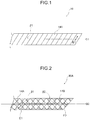
- FIG. 1 is a side view showing Specific Embodiment A of the piezoelectric substrate according to the first embodiment.
- a piezoelectric substrate 10 of Specific Embodiment A includes a first piezoelectric body 14A having an elongated shape, and does not include a core material.
- the first piezoelectric body 14A is helically wound in one direction with respect to a helical axis G1 at a helix angle ⁇ 1, from one end to the other, such that no gap is formed and no space is present around the helical axis G1. Further, the first piezoelectric body 14A is impregnated with an adhesive (not shown in the figure), and adjacent portions of the first piezoelectric body 14A are adhered with each other by the adhesive.
- the "helix angle ⁇ 1" refers to the angle formed between the helical axis G1, and the arrangement direction of the first piezoelectric body 14A with respect to the helical axis G1.
- the first piezoelectric body 14A is wound in the left-handed direction with respect to the helical axis G1. Specifically, when the piezoelectric substrate 10 is seen from one end side of the helical axis G1 (on the right side, in the case of FIG. 1 ), the first piezoelectric body 14A is wound in the left-handed direction, from the near side to the far side.
- the main direction of orientation of the helical chiral polymer (A) included in the first piezoelectric body 14A is shown with a two-way arrow E1.
- the main direction of orientation of the helical chiral polymer (A) is substantially parallel to the arrangement direction (the length direction of the first piezoelectric body 14A) of the first piezoelectric body 14A.
- a shear force is applied to the helical chiral polymer (A) included in the first piezoelectric body 14A, and polarization occurs in the helical chiral polymer (A).
- the polarization of the helical chiral polymer (A) occurs in the radial direction of the piezoelectric substrate 10, and it is thought that the polarization occurs in that direction in a phase matched manner. This allows for an effective detection of a voltage signal proportional to the tensile force.
- the relative positions of the portions of the first piezoelectric body 14A are less likely to be displaced, allowing a tensile force to be more effectively applied to the first piezoelectric body 14A.
- the piezoelectric substrate 10 has an excellent bendability and flexibility, due to including no core material.
- the piezoelectric substrate 10 of Specific Embodiment A allows the piezoelectric substrate 10 of Specific Embodiment A to have an excellent piezoelectric sensitivity, an excellent piezoelectric output stability, and an improved resistance to a load such as repeated bending or to deformation.
- FIG. 2 is a side view showing Specific Embodiment B1 of the piezoelectric substrate according to the first embodiment.
- a piezoelectric substrate 10A of Specific Embodiment B1 includes the first piezoelectric body 14A, and a second piezoelectric body 14B, and does not include a core material.
- the first piezoelectric body 14A and the second piezoelectric body 14B are alternately crossed with each other to be formed into a braided structure.
- the helical chiral polymer (A) included in the first piezoelectric body 14A has a chirality different from the chirality of the helical chiral polymer (A) included in the second piezoelectric body 14B.
- the first piezoelectric body 14A is helically wound in the left-handed direction with respect to a helical axis G2 at the helix angle ⁇ 1
- the second piezoelectric body 14B is helically wound in the right-handed direction at a helix angle ⁇ 2
- the first piezoelectric body 14A and the second piezoelectric body 14B are alternately crossed with each other.
- the main direction of orientation (two-way arrow E1) of the helical chiral polymer (A) included in the first piezoelectric body 14A is substantially parallel to the arrangement direction of the first piezoelectric body 14A.
- the main direction of orientation (two-way arrow E2) of the helical chiral polymer (A) included in the second piezoelectric body 14B is substantially parallel to the arrangement direction of the second piezoelectric body 14B.
- polarization occurs in both the helical chiral polymer (A) included in the first piezoelectric body 14A, and the helical chiral polymer (A) included in the second piezoelectric body 14B.
- the polarization of each of the helical chiral polymers (A) occurs in the radial direction of the piezoelectric substrate 10A. This allows for an effective detection of a voltage signal proportional to the tensile force.
- the piezoelectric substrate 10A has an excellent bendability and flexibility, due to having a braided structure with no core material.
- the piezoelectric substrate 10A of Specific Embodiment B1 to have an excellent piezoelectric sensitivity, an excellent piezoelectric output stability, and an improved resistance to a load such as repeated bending or to deformation.
- the piezoelectric substrate 10A of Specific Embodiment B1 when a tensile force is applied to the length direction of the piezoelectric substrate 10A, a shear stress is applied to the first piezoelectric body 14A wound in the left-handed direction and the second piezoelectric body 14B wound in the right-handed direction, which are formed into the braided structure, and the direction of polarization in the first piezoelectric body 14A matches the direction of polarization in the second piezoelectric body 14B.
- This causes an increase in volume fractions contributing to the piezoelectric performance in the first piezoelectric body 14A and the second piezoelectric body 14B, thereby further improving the piezoelectric performance.
- the piezoelectric substrate 10A of Specific Embodiment B1 can be suitably used as a constituent member in a product which needs to conform to a three-dimensional plane, for example, a wearable product (such as a piezoelectric woven fabric, a piezoelectric knitted fabric, a piezoelectric device, a force sensor, or a device for obtaining biological information, to be described later).
- a wearable product such as a piezoelectric woven fabric, a piezoelectric knitted fabric, a piezoelectric device, a force sensor, or a device for obtaining biological information, to be described later.
- the piezoelectric substrate of Specific Embodiment B2 has the same configuration as the piezoelectric substrate 10A of Specific Embodiment B1, except for including a fiber instead of the second piezoelectric body 14B in the piezoelectric substrate 10A of Specific Embodiment B1 shown in FIG. 2 .
- the piezoelectric substrate of Specific Embodiment B2 includes the first piezoelectric body and the fiber, and does not include a core material, wherein the first piezoelectric body and the fiber are alternately crossed with each other to be formed into a braided structure.
- the fiber in Specific Embodiment B2 is a fiber which does not have piezoelectricity. In the case of this embodiment, the winding direction of the fiber may be right-handed or left-handed.
- the piezoelectric substrate of Specific Embodiment B2 has an excellent bendability and flexibility, due to having a braided structure with no core material.
- the piezoelectric substrate of Specific Embodiment B2 to also have an excellent piezoelectric sensitivity, an excellent piezoelectric output stability, and an improved resistance to a load such as repeated bending or to deformation.
- the piezoelectric substrate according to the first embodiment includes a first piezoelectric body having an elongated shape.
- the first piezoelectric body is a piezoelectric body including a helical chiral polymer (A) having an optical activity.
- the first piezoelectric body in the first embodiment includes a helical chiral polymer (A) having an optical activity.
- helical chiral polymer (A) having an optical activity refers to a polymer having a molecular structure in the form of a helix and having a molecular optical activity.
- Examples of the helical chiral polymer (A) include polypeptides, cellulose derivatives, polylactic acid polymers, polypropylene oxide, and poly( ⁇ -hydroxybutyric acid).
- polypeptide examples include poly(y-benzyl glutarate), and poly(y-methyl glutarate).
- cellulose derivative examples include cellulose acetate, and cyanoethyl cellulose.
- the helical chiral polymer (A) preferably has an optical purity of 95.00% ee or more, more preferably 96.00% ee or more, still more preferably 99.00% ee or more, and further still more preferably 99.99% ee or more, from the viewpoint of improving the piezoelectricity of the first piezoelectric body.
- the optical purity of the helical chiral polymer (A) is desirably 100.00% ee. When the optical purity of the helical chiral polymer (A) is within the above range, packing of polymer crystals exhibiting piezoelectricity becomes denser, resulting in an enhanced piezoelectricity.
- the optical purity of the helical chiral polymer (A) is defined as: ⁇ a numerical value obtained by dividing "the difference (absolute value) between the amount of L-form [% by mass] of the helical chiral polymer (A) and the amount of D-form [% by mass] of the helical chiral polymer (A)" by "the total amount of the amount of L-form [% by mass] of the helical chiral polymer (A) and the amount of D-form [% by mass] of the helical chiral polymer (A)" ⁇ , multiplied by ⁇ 100 ⁇ .
- the helical chiral polymer (A) is preferably a polymer having a main chain including a repeating unit represented by the following Formula (1), from the viewpoint of increasing the optical purity and improving the piezoelectricity.
- Examples of the polymer having a main chain including a repeating unit represented by the following Formula (1) include a polylactic acid polymer.
- polylactic acid polymer refers to "polylactic acid (a polymer consisting of repeating units derived from a monomer selected from L-lactic acid or D-lactic acid)", a “copolymer of L-lactic acid or D-lactic acid and a compound copolymerizable with the L-lactic acid or the D-lactic acid", or a mixture of both.
- polylactic acid is preferred, and a homopolymer of L-lactic acid (PLLA, also simply referred to as "L-form”) or a homopolymer of D-lactic acid (PDLA, also simply referred to as "D-form”) is most preferred.
- PLLA L-lactic acid
- PDLA D-lactic acid
- Polylactic acid is a polymer having a long chain structure formed by polymerization of lactic acid via ester bonds.
- polylactic acid can be formed by: a lactide method in which lactide is produced as an intermediate; a direct polymerization method in which lactic acid is heated in a solvent under reduced pressure, followed by polymerization while removing water; or the like.
- polylactic acid examples include: a homopolymer of L-lactic acid; a homopolymer of D-lactic acid; a block copolymer containing a polymer of at least one of L-lactic acid or D-lactic acid; and a graft copolymer containing a polymer of at least one of L-lactic acid or D-lactic acid.
- Examples of the "compound copolymerizable with L-lactic acid or D-lactic acid” include: hydroxycarboxylic acids such as glycolic acid, dimethyl glycolic acid, 3-hydroxybutyric acid, 4-hydroxybutyric acid, 2-hydroxypropanoic acid, 3-hydroxypropanoic acid, 2-hydroxyvaleric acid, 3-hydroxyvaleric acid, 4-hydroxyvaleric acid, 5-hydroxyvaleric acid, 2-hydroxycaproic acid, 3-hydroxycaproic acid, 4-hydroxycaproic acid, 5-hydroxycaproic acid, 6-hydroxycaproic acid, 6-hydroxymethylcaproic acid, and mandelic acid; cyclic esters such as glycolide, ⁇ -methyl- ⁇ -valerolactone, ⁇ -valerolactone, and ⁇ -caprolactone; polyvalent carboxylic acids such as oxalic acid, malonic acid, succinic acid, glutaric acid, adipic acid, pimelic acid, azelaic acid, sebacic acid, undecanedioic acid,
- Examples of the "copolymer of L-lactic acid or D-lactic acid and a compound copolymerizable with the L-lactic acid or the D-lactic acid” include block copolymers and graft copolymers having a polylactic acid sequence capable of forming a helical crystal.
- the concentration of a structure derived from a copolymer component in the helical chiral polymer (A) is preferably 20 mol% or less.
- the concentration of the structure derived from the copolymer component is preferably 20 mol% or less, with respect to the total number of moles of a structure derived from lactic acid and the structure derived from the compound (copolymer component) copolymerizable with lactic acid, in the polylactic acid polymer.
- the polylactic acid polymer can be produced, for example, by: the method disclosed in JP-ANo. 59-096123 or JP-ANo. 7-033861 , in which lactic acid is directly subjected to dehydration condensation; the method disclosed in US Patent No. 2,668,182 , US Patent No. 4,057,357 , or the like, in which ring-opening polymerization is carried out using lactide, which is a cyclic dimer of lactic acid; or the like.
- the helical chiral polymer (A) preferably has a weight average molecular weight (Mw) of 50,000 to one million.
- the first piezoelectric body has an improved mechanical strength.
- the Mw is preferably 100,000 or more, and more preferably 200,000 or more.
- the moldability in the case of obtaining the first piezoelectric body by molding is improved.
- the Mw is preferably 800,000 or less, and more preferably 300,000 or less.
- the helical chiral polymer (A) preferably has a molecular weight distribution (Mw/Mn) of from 1.1 to 5, and more preferably from 1.2 to 4, from the viewpoint of improving the strength of the first piezoelectric body.
- Mw/Mn molecular weight distribution
- the molecular weight distribution is still more preferably from 1.4 to 3.
- Each of the weight average molecular weight (Mw) and the molecular weight distribution (Mw/Mn) of the helical chiral polymer (A) refers to a value measured by gel permeation chromatography (GPC).
- the Mn as used herein is a number average molecular weight of the helical chiral polymer (A).
- the first piezoelectric body is dissolved in a solvent (such as chloroform) at 40°C to prepare a sample solution having a concentration of 1 mg/ml.
- a solvent such as chloroform
- a quantity of 0.1 ml of the sample solution prepared with a solvent [chloroform] is introduced into the column, at a temperature of 40°C, and at a flow velocity of 1 ml/min.
- the concentration of the sample in the sample solution, which has been separated by the column, is measured by a differential refractometer.
- a universal calibration curve is prepared using a polystyrene standard sample, to calculate the weight average molecular weight (Mw) and the molecular weight distribution (Mw/Mn) of the helical chiral polymer (A).
- a commercially available polylactic acid can be used as a polylactic acid polymer, which is an example of the helical chiral polymer (A).
- Examples of commercially available products thereof include: PURASORB (PD, PL), manufactured by PURAC Biomaterials; LACEA (H-100, H-400), manufactured by Mitsui Chemicals, Inc.; and INGEO (trade mark) biopolymer, manufactured by NatureWorks LLC.
- PURASORB PD, PL
- LACEA H-100, H-400
- INGEO trade mark
- the polylactic acid polymer is produced by the lactide method or the direct polymerization method.
- the first piezoelectric body in the first embodiment may include one kind of the above described helical chiral polymer (A), or two or more kinds thereof.
- the content of the helical chiral polymer (A) (the total content, in cases where two or more kinds thereof are included) in the first piezoelectric body in the first embodiment is preferably 80% by mass or more with respect to the total amount of the first piezoelectric body.
- the first piezoelectric body in the first embodiment further includes a stabilizer (B) containing one or more functional groups selected from the group consisting of carbodiimide group, epoxy group, and isocyanate group, within one molecule, and having a weight average molecular weight of from 200 to 60,000. This allows for further improving resistance to moist heat.
- a stabilizer B containing one or more functional groups selected from the group consisting of carbodiimide group, epoxy group, and isocyanate group, within one molecule, and having a weight average molecular weight of from 200 to 60,000. This allows for further improving resistance to moist heat.
- stabilizer (B) As the stabilizer (B), it is possible to use the "stabilizer (B)" described in paragraphs 0039 to 0055 in WO 2013/054918 .
- Examples of a compound (carbodiimide compound) which contains a carbodiimide group within one molecule and which can be used as the stabilizer (B) include a monocarbodiimide compound, a polycarbodiimide compound, and a cyclic carbodiimide compound.
- dicyclohexyl carbodiimide bis-2,6-diisopropylphenyl carbodiimide or the like can be suitably used.
- polycarbodiimide compound one prepared by any of various kinds of methods can be used. It is possible to use a polycarbodiimide compound prepared by a conventional method of producing a polycarbodiimide (such as the method described in US Patent No. 2941956 , JP-B No. S47-33279 , J. Org. Chem. 28, 2069 to 2075 (1963 ), or Chemical Review 1981, Vol. 81, No.4, p 619 to 621 ). Specifically, a carbodiimide compound disclosed in JP-B No. 4084953 can also be used.
- polycarbodiimide compound examples include poly(4,4' -dicyclohexylmethanecarbodiimide), poly(N,N'-di-2,6-diisopropylphenylcarbodiimide), and poly(1,3,5-triisopropylphenylene-2,4-carbodiimide).
- the cyclic carbodiimide compound can be synthesized according to the method described in JP-ANo. 2011-256337 , or the like.
- the carbodiimide compound may be a commercially available product, and examples thereof include: B2756 (trade name), manufactured by Tokyo Chemical Industry Co., Ltd.; CARBODILITE LA-1 (trade name), manufactured by Nisshinbo Chemical Inc.; STABAXOL P, STABAXOL P400 and STABAXOL I (all of these are trade names) manufactured by Rhein Chemie Rheinau GmbH.
- Examples of a compound (isocyanate compound) which contains an isocyanate group within one molecule and which can be used as the stabilizer (B) include 3-(triethoxysilyl)propyl isocyanate, 2,4-tolylene diisocyanate, 2,6-tolylene diisocyanate, m-phenylene diisocyanate, p-phenylene diisocyanate, 4,4'-diphenylmethane diisocyanate, 2,4'-diphenylmethane diisocyanate, 2,2'-diphenylmethane diisocyanate, xylylene diisocyanate, hydrogenated xylylene diisocyanate, and isophorone diisocyanate.
- Examples of a compound (epoxy compound) which contains an epoxy group within one molecule and which can be used as the stabilizer (B) include phenyl glycidyl ether, diethylene glycol diglycidyl ether, bisphenol A-diglycidyl ether, hydrogenated bisphenol A-diglycidyl ether, phenol novolac type epoxy resin, cresol novolac type epoxy resin, and epoxidized polybutadiene.
- the weight average molecular weight of the stabilizer (B) is from 200 to 60,000, as described above, but more preferably from 200 to 30,000, and still more preferably from 300 to 18,000.
- Having a molecular weight within the above range facilitates the movement of the stabilizer (B), and an effect of improving the resistance to moist heat will be more effectively exhibited.
- the stabilizer (B) has a weight average molecular weight of from 200 to 900.
- a weight average molecular weight of from 200 to 900 roughly corresponds with a number average molecular weight of from 200 to 900.
- the weight average molecular weight is from 200 to 900, there is a case in which the molecular weight distribution is 1.0, and in this case, the "weight average molecular weight of from 200 to 900" can be simply referred to as a "molecular weight of from 200 to 900".
- the first piezoelectric body in the first embodiment includes the stabilizer (B)
- the first piezoelectric body may include only one kind of the stabilizer (B), or two or more kinds thereof.
- the content of the stabilizer (B) is preferably from 0.01 parts by mass to 10 parts by mass, more preferably from 0.01 parts by mass to 5 parts by mass, still more preferably from 0.1 parts by mass to 3 parts by mass, and particularly preferably from 0.5 parts by mass to 2 parts by mass, with respect to 100 parts by mass of the helical chiral polymer (A).
- the content of the stabilizer (B) is 0.01 parts by mass or more, the resistance to moist heat will be further improved.
- the content of the stabilizer (B) is 10 parts by mass or less, on the other hand, a decrease in the transparency can be further prevented.
- Examples of preferred embodiments of the stabilizer (B) include an embodiment in which a stabilizer (B1) containing one or more functional groups selected from the group consisting of carbodiimide group, epoxy group, and isocyanate group, and having a number average molecular weight of from 200 to 900, and a stabilizer (B2) containing two or more of the one or more functional groups selected from the group consisting of carbodiimide group, epoxy group, and isocyanate group within one molecule, and having a number average molecular weight of from 1,000 to 60,000, are used in combination.
- the stabilizer (B1) having a number average molecular weight of from 200 to 900 has a weight average molecular weight of approximately from 200 to 900; that is, the values of the number average molecular weight and the weight average molecular weight of the stabilizer (B1) are roughly the same.
- the stabilizer (B1) and the stabilizer (B2) in combination it is preferred that the stabilizer (B1) is included in a larger amount, from the viewpoint of improving the transparency.
- the content of the stabilizer (B2) is preferably within the range of from 10 parts by mass to 150 parts by mass, and more preferably from 50 parts by mass to 100 parts by mass, with respect to 100 parts by mass of the stabilizer (B1).
- stabilizers B-1 to B-3 Specific examples (stabilizers B-1 to B-3) of the stabilizer (B) are shown below.
- the first piezoelectric body in the first embodiment may include any of other components, if necessary.
- Examples of other components include known resins such as polyvinylidene fluorides, polyethylene resins, and polystyrene resins; known inorganic fillers such as silica, hydroxyapatite, and montmorillonite; known crystal nucleating agents such as phthalocyanine; and stabilizers other than the stabilizer (B).
- resins such as polyvinylidene fluorides, polyethylene resins, and polystyrene resins
- known inorganic fillers such as silica, hydroxyapatite, and montmorillonite
- known crystal nucleating agents such as phthalocyanine
- stabilizers other than the stabilizer (B) include known resins such as polyvinylidene fluorides, polyethylene resins, and polystyrene resins; known inorganic fillers such as silica, hydroxyapatite, and montmorillonite; known crystal nucleating agents such as phthalocyanine; and stabilizers other than the stabilizer (B
- Examples of the inorganic filler and the crystal nucleating agent include components disclosed in paragraphs 0057 to 0058 in WO 2013/054918 .
- the first piezoelectric body in the first embodiment has a degree of orientation F of 0.5 or more but less than 1.0.
- the degree of orientation F is preferably 0.7 or more but less than 1.0, and more preferably 0.8 or more but less than 1.0.
- the first piezoelectric body has a degree of orientation F of 0.5 or more, molecular chains of the helical chiral polymer (A) (such as molecular chains of polylactic acid) which are aligned in the stretching direction are present in a higher number. This leads to an increased ratio of oriented crystals formed, thereby allowing the piezoelectric body to exhibit an even higher piezoelectricity.
- A helical chiral polymer
- the piezoelectric body When the first piezoelectric body has a degree of orientation F of less than 1.0, on the other hand, the piezoelectric body will have a further improved longitudinal tear strength.
- the degree of crystallinity of the first piezoelectric body in the first embodiment is a value measured by the X-ray diffraction (wide-angle x-ray diffraction measurement) described above.
- the first piezoelectric body in the first embodiment preferably has a degree of crystallinity of from 20% to 80%, more preferably from 25% to 70%, and still more preferably from 30% to 60%.
- the first piezoelectric body has a degree of crystallinity of 20% or more, a high piezoelectricity can be maintained.
- a high piezoelectricity can be maintained.
- a high transparency is maintained in the first piezoelectric body.
- a piezoelectric film to be used as a raw material of the first piezoelectric body is produced by stretching, having a degree of crystallinity of 80% or less makes the film less susceptible to whitening or rupture, thereby facilitating the production of the first piezoelectric body.
- a raw material (such as polylactic acid) of the first piezoelectric body is produced by melt spinning, followed by stretching, for example, having a degree of crystallinity of 80% or less enables to produce a fiber having a high bendability and flexible characteristics, thereby facilitating the production of the first piezoelectric body.
- the first piezoelectric body in the first embodiment is not required to have transparency, in particular; however, the first piezoelectric body may, of course, have transparency.
- the transparency of the first piezoelectric body can be evaluated by measuring an internal haze.
- the internal haze of the first piezoelectric body as used herein refers to a haze from which a haze caused by the shape of an outer surface of the first piezoelectric body is excluded.
- the internal haze to visible light is preferably 5% or less. From the viewpoint of further improving the transparency and the longitudinal tear strength, the internal haze is more preferably 2.0% or less, and still more preferably 1.0% or less.
- the lower limit value of the internal haze of the first piezoelectric body may be, for example, 0.01%, but not particularly limited thereto.
- the internal haze of the first piezoelectric body is a value obtained by measuring the first piezoelectric body having a thickness of from 0.03 mm to 0.05 mm, using a haze measuring apparatus [TC-H III DPK, manufactured by Tokyo Denshoku Co., Ltd.] in accordance with JIS-K7105, at 25°C.
- a sample 1 is prepared by sandwiching only a silicone oil (SHINETSU SILICONE (trademark), model number: KF96-100CS, manufactured by Shin-Etsu Chemical Co., Ltd.) between two glass plates, and the haze (hereinafter, referred to as "haze (H2)") of the sample 1 in the thickness direction is measured.
- a silicone oil SHINETSU SILICONE (trademark), model number: KF96-100CS, manufactured by Shin-Etsu Chemical Co., Ltd.
- a sample 2 is prepared by arranging a plurality of the first piezoelectric bodies whose surfaces are uniformly wetted with the silicone oil, without gaps, between two glass plates, and the haze (hereinafter, referred to as "haze (H3)") of the sample 2 in the thickness direction is measured.
- the measurements of the haze (H2) and the haze (H3) are each carried out under the following measurement conditions, and using the following apparatus.
- the first piezoelectric body preferably has a tensile elastic modulus of from 0.1 GPa to 100 GPa, and more preferably from 1 GPa to 50 GPa.
- the tensile elastic modulus refers to a tensile elastic modulus in the stretching direction (MD direction).
- the first piezoelectric body may include polyvinylidene fluoride, along with the helical chiral polymer (A) (such as a polylactic acid polymer), from the viewpoint of further improving the tensile elastic modulus.
- A helical chiral polymer
- the first piezoelectric body preferably has a tensile elastic modulus of from 1 GPa to 10 GPa.
- the method of measuring the tensile elastic modulus of the first piezoelectric body is as follows.
- the first piezoelectric body is a film (an example of an elongated flat plate form)
- a rectangular test specimen (film) having a length of 100 mm is prepared.
- a value obtained by dividing the mass (g) of the test specimen by the density (g/cc) of the material thereof is taken as the volume of the test specimen, and a value obtained by dividing the thus obtained volume by the area (product of length and width) of the main surface of the film is taken as an average thickness of the test specimen. Based on the thus obtained thickness and the width of the test specimen, a cross-sectional area of the test specimen is calculated.
- An S-S curve is plotted from the amount of stress and strain when a tensile force is applied to the test specimen, using a tensile tester (TENSILON RTG1250, manufactured by A&D Co., Ltd.), and the tensile elastic modulus is calculated from a slope of initial linear strain region of the S-S curve.
- TENSILON RTG1250 manufactured by A&D Co., Ltd.
- the first piezoelectric body is a thread (an example of a fibrous form)
- a test specimen (thread) having a length of 100 mm is prepared.
- a value obtained by dividing the mass (g) of the test specimen by the density (g/cc) of the material thereof is taken as the volume of the test specimen, and a value obtained by dividing the thus obtained volume by the length of the thread is taken as an average cross-sectional area of the test specimen.
- An S-S curve is plotted from the amount of stress and strain when a tensile force is applied to the test specimen, using a tensile tester, and the tensile elastic modulus is calculated from the slope of the initial linear strain region of the S-S curve.
- the piezoelectric substrate according to the first embodiment includes the first piezoelectric body having an elongated shape.
- the first piezoelectric body having an elongated shape is preferably a piezoelectric body in a fibrous form (in the form of a thread) composed of a single bundle or a plurality of bundles, or a piezoelectric body in the form of an elongated flat plate.
- piezoelectric body in a fibrous form hereinafter, also referred to as a "fibrous piezoelectric body”
- fibrous piezoelectric body the piezoelectric body in the form of an elongated flat plate
- elongated flat plate-like piezoelectric body an elongated flat plate-like piezoelectric body
- the fibrous piezoelectric body may be, for example, a monofilament thread or a multifilament thread.
- the monofilament thread preferably has a single fiber fineness of from 3 dtex to 30 dtex, and more preferably from 5 dtex to 20 dtex.
- the monofilament thread has a single fiber fineness of less than 3 dtex, it becomes difficult to handle the thread in a woven fabric preparation step or a weaving step.
- the monofilament thread has a single fiber fineness exceeding 30 dtex, on the other hand, fusion bonding is more likely to occur between the threads.
- the monofilament thread may also be one obtained commercially or otherwise.
- the multifilament thread preferably has a total fineness of from 30 dtex to 600 dtex, and more preferably from 100 dtex to 400 dtex.
- the multifilament thread it is possible to use a one-step thread such as a spin draw thread, or alternatively, a two-step thread obtained by stretching a UDY (unstretched thread) or a POY (highly-oriented unstretched thread).
- the multifilament thread may also be one obtained commercially or otherwise.
- Examples of commercially available products of polylactic acid monofilament threads and polylactic acid multifilament threads which can be used include: ECODEAR (registered trademark) PLA, manufactured by Toray Industries, Inc.; TERRAMAC (registered trademark), manufactured by Unitika Ltd.; and PLASTARCH (registered trademark) manufactured by Kuraray Co., Ltd.
- the method of producing the fibrous piezoelectric body is not particularly limited, and the fibrous piezoelectric body can be produced by a known method.
- a filament thread (such as a monofilament thread or a multifilament thread) as the first piezoelectric body can be obtained by melt spinning a raw material (such as polylactic acid), followed by stretching the resultant (melt spinning drawing method). After the spinning, it is preferred to maintain the temperature of the atmosphere in the vicinity of the thread within a constant range, until the thread is cooled and solidified.
- a raw material such as polylactic acid
- the filament thread as the first piezoelectric body may be obtained, for example, by further separating the filament thread obtained by the melt spinning drawing.
- the fibrous piezoelectric body can be formed to have any of various types of cross-sectional shapes, in a cross section taken in the direction vertical to the longitudinal direction of the fibrous piezoelectric body, such as for example, a cross-sectional shape in the form of a circle, an oval, a rectangle, a cocoon, a ribbon, a quatrefoil, a star, or a deformed shape.
- the elongated flat plate-like piezoelectric body may be, for example, an elongated flat plate-like piezoelectric body (such as a slit ribbon) obtained by slitting a piezoelectric film produced by a known method or a piezoelectric film obtained commercially or otherwise.
- an elongated flat plate-like piezoelectric body such as a slit ribbon obtained by slitting a piezoelectric film produced by a known method or a piezoelectric film obtained commercially or otherwise.
- a functional layer may be provided on at least one of the main surfaces of the first piezoelectric body, to the extent that the effect of the first embodiment is not impaired.
- the functional layer may have a monolayer structure, or a structure composed of two or more layers.
- each of the functional layer provided on one of the main surfaces (hereinafter, referred to as a "top surface” for convenience) and the functional layer provided on the other main surface (hereinafter, referred to as a “back surface” for convenience) may independently have a monolayer structure or a structure composed of two or more layers.
- the functional layer may be, for example, any of various kinds of functional layers.
- the functional layer examples include an easily-adhesive layer, a hard coat layer, a refractive index controlling layer, an anti-reflection layer, an anti-glare layer, a slippery layer, an anti-blocking layer, a protective layer, an adhesive layer, an antistatic layer, a heat dissipation layer, a UV-absorbing layer, an Anti-Newton ring layer, a light scattering layer, a polarization layer, a gas barrier layer, and a hue adjustment layer.
- an easily-adhesive layer a hard coat layer, a refractive index controlling layer, an anti-reflection layer, an anti-glare layer, a slippery layer, an anti-blocking layer, a protective layer, an adhesive layer, an antistatic layer, a heat dissipation layer, a UV-absorbing layer, an Anti-Newton ring layer, a light scattering layer, a polarization layer, a gas barrier layer, and a hue adjustment layer.
- the functional layer may be a layer composed of two or more of these layers.
- the functional layer may also be a layer having two or more functions of these layers.
- the functional layer provided on the side of the top surface may be the same as, or different from the functional layer provided on the side of the back surface.
- the effects provided by the functional layer include an effect of fixing defects, for example, an effect of filling die lines and dents, on the surface of the elongated flat plate-like piezoelectric body, thereby improving the appearance.
- a lower difference in refractive index between the elongated flat plate-like piezoelectric body and the functional layer results in a lower reflection at the interface of the elongated flat plate-like piezoelectric body and the functional layer, thereby further improving the appearance.
- the functional layer preferably includes at least one of the easily-adhesive layer, the hard coat layer, the antistatic layer, the anti-blocking layer, or the protective layer. This facilitates the application of the piezoelectric substrate to a piezoelectric device (such as a piezoelectric woven fabric or a piezoelectric knitted fabric), a force sensor, an actuator, or a device for obtaining biological information.
- a piezoelectric device such as a piezoelectric woven fabric or a piezoelectric knitted fabric
- a force sensor such as a piezoelectric woven fabric or a piezoelectric knitted fabric
- an actuator or a device for obtaining biological information.
- an electrode layer may be provided on at least one (preferably both) of the main surfaces of the first piezoelectric body.
- the electrode layer may be provided in contact with the elongated flat plate-like piezoelectric body, or provided with the functional layer interposed therebetween.
- the piezoelectric substrate according to the first embodiment which includes the elongated flat plate-like piezoelectric body in the above described arrangement, is used as one of the components of, for example, a piezoelectric device (such as a piezoelectric woven fabric or a piezoelectric knitted fabric), a force sensor, an actuator, or a device for obtaining biological information
- a piezoelectric device such as a piezoelectric woven fabric or a piezoelectric knitted fabric
- a force sensor such as a piezoelectric woven fabric or a piezoelectric knitted fabric
- Materials for the functional layer are not particularly limited, and examples thereof include: inorganic substances such as metals and metal oxides; organic substances such as resins; and composite compositions containing a resin(s) and fine particles.
- the resin it is possible to use, for example, a cured product obtained by curing a resin, by controlling the temperature or using an active energy ray. In other words, a curable resin can be used as the resin.
- curable resin examples include at least one material (curable resin) selected from the group consisting of: acrylic compounds, methacrylic compounds, vinyl compounds, allyl compounds, urethane compounds, epoxy compounds, epoxide compounds, glycidyl compounds, oxetane compounds, melamine compounds, cellulose compounds, ester compounds, silane compounds, silicone compounds, siloxane compounds, silica-acrylic hybrid compounds, and silica-epoxy hybrid compounds.
- curable resin selected from the group consisting of: acrylic compounds, methacrylic compounds, vinyl compounds, allyl compounds, urethane compounds, epoxy compounds, epoxide compounds, glycidyl compounds, oxetane compounds, melamine compounds, cellulose compounds, ester compounds, silane compounds, silicone compounds, siloxane compounds, silica-acrylic hybrid compounds, and silica-epoxy hybrid compounds.
- an acrylic compound, an epoxy compound, or a silane compound is more preferred.
- the metal may be, for example, at least one selected from Al, Si, Ti, V, Cr, Fe, Co, Ni, Cu, Zn, In, Sn, W, Ag, Au, Pd, Pt, Sb, Ta or Zr; or an alloy thereof.
- the metal oxide may be, for example, at least one of titanium oxide, zirconium oxide, zinc oxide, niobium oxide, antimony oxide, tin oxide, indium oxide, cerium oxide, aluminum oxide, silicon oxide, magnesium oxide, yttrium oxide, ytterbium oxide, or tantalum oxide; or a composite oxide thereof.
- fine particles examples include fine particles of metal oxides as described above; and fine particles of resins such as fluororesins, silicone resins, styrene resins, and acrylic resins. Examples also include hollow fine particles which are the above described fine particles having internal cavities.
- the fine particles preferably have an average primary particle size of from 1 nm to 500 nm, more preferably from 5 nm to 300 nm, and still more preferably from 10 nm to 200 nm, from the viewpoint of improving the transparency. Having an average primary particle size of 500 nm or less prevents the scattering of a visible light, whereas having an average primary particle size of 1 nm or more prevents secondary aggregation of fine particles; therefore, an average primary particle size within this range is desirable from the viewpoint of maintaining the transparency.
- the functional layer preferably has a film thickness within the range of from 0.01 ⁇ m to 10 ⁇ m, but not particularly limited thereto.
- the upper limit value of the thickness is more preferably 6 ⁇ m or less, and still more preferably 3 ⁇ m or less. Further, the lower limit value thereof is more preferably 0.01 ⁇ m or more, and sill more preferably 0.02 ⁇ m or more.
- the thickness of the functional layer refers to the thickness of the entire multilayer film.
- the functional layer may be provided on both surfaces of the elongated flat plate-like piezoelectric body.
- the functional layers may have a refractive index different from each other.
- the method of producing the elongated flat plate-like piezoelectric body is not particularly limited, and the elongated flat plate-like piezoelectric body can be produced by a known method.
- the first piezoelectric body can be produced from a piezoelectric film, by a method in which a raw material (such as polylactic acid) is formed in the form of a film to obtain an unstretched film, and the resulting unstretched film is subjected to stretching and crystallization, followed by slitting the resulting piezoelectric film.
- a raw material such as polylactic acid
- slitting refers to cutting the piezoelectric film into an elongated shape.
- Either the stretching or the crystallization may be carried out first. Further, a method may also be used in which an unstretched film is subjected to pre-crystallization, stretching, and crystallization (annealing) are carried out in this order.
- the stretching of the film may be carried out by uniaxial stretching or biaxial stretching. In the case of stretching the film by biaxial stretching, the draw ratio in one direction (the main stretching direction) is preferably adjusted to a higher magnification.
- the piezoelectric substrate according to the first embodiment may include a fiber.
- the fiber is wound in a direction different from the one direction (the winding direction of the first piezoelectric body), and that the first piezoelectric body and the fiber are alternately crossed with each other to be formed into a braided structure.
- the winding direction (right-handed or left-handed direction) of the fiber may be the same as, or different from the winding direction of the first piezoelectric body.
- the fiber is not particularly limited, and examples thereof include: polymer fibers such as aramid fibers, polyester fibers, acrylic fibers, polyethylene fibers, polypropylene fibers, vinyl chloride fibers, polysulfone fibers, polyether fibers, and polyurethane fibers; natural fibers such as cotton, hemp, silk, and cellulose; semi-synthetic fibers such as acetate; regenerated fibers such as rayon and cupra; and glass fibers. Further, the fiber may also be, for example, the second piezoelectric body in the form of a fiber.
- These fibers may be used singly, or in combination of two or more kinds thereof.
- the fiber may be, for example, a monofilament thread or a multifilament thread.
- the monofilament thread may have, for example, a single fiber fineness within the same range as the single fiber fineness of the monofilament thread in the previously described fibrous piezoelectric body.
- the multifilament thread may have, for example, a total fineness within the same range as the total fineness of the multifilament thread in the previously described fibrous piezoelectric body.
- the piezoelectric substrate according to the first embodiment may include a second piezoelectric body having an elongated shape.
- the second piezoelectric body is wound in a direction different from the one direction (the winding direction of the first piezoelectric body), and that the first piezoelectric body and the second piezoelectric body are alternately crossed with each other to be formed into a braided structure.
- the second piezoelectric body preferably has the same properties as the properties of the first piezoelectric body.
- the second piezoelectric body preferably has other properties which are the same as the first piezoelectric body, in addition to the properties described above.
- the helical chiral polymer (A) included in the first piezoelectric body has a chirality different from the chirality of the helical chiral polymer (A) included in the second piezoelectric body.
- the second piezoelectric body may have properties different from the properties of the first piezoelectric body.
- the second piezoelectric body may include the stabilizer (B) and any of other components, in the same manner as the previously described first piezoelectric body.
- the first piezoelectric body in the first embodiment preferably includes an adhesive composition, from the viewpoint of improving the piezoelectric sensitivity, and the piezoelectric output stability.
- adheresion is used as a concept encompassing the concept of "pressure-sensitive adhesion”. Further, the term “adhesive” is used as a concept encompassing the concept of "pressure-sensitive adhesive”.
- the adhesive composition is sometimes referred to as the "adhesive", in the description given below.
- the adhesive is used in order to mechanically integrate the portions of the first piezoelectric body.
- the relative positions of the portions of the first piezoelectric body are less likely to be displaced when a tensile force is applied to the piezoelectric substrate according to the first embodiment, making the tensile force to be more efficiently applied to the first piezoelectric body.
- This allows for an effective detection of a voltage output proportional to the tensile force.
- the piezoelectric sensitivity, and the piezoelectric output stability are further improved.
- the first piezoelectric body includes the adhesive, the absolute value of the amount of electric charge generated (surface potential generated) per unit tensile force, in the piezoelectric substrate, will be further increased.
- a piezoelectric substrate in which the first piezoelectric body does not include the adhesive flexible properties will be maintained even after being processed into a piezoelectric fiber (such as a piezoelectric knitted fabric, or a piezoelectric woven fabric) to be described later, enabling to provide a favorable feeling of fit when used in a wearable sensor or the like.
- a piezoelectric fiber such as a piezoelectric knitted fabric, or a piezoelectric woven fabric
- Examples of materials which can be used include: epoxy adhesives, urethane adhesives, vinyl acetate resin emulsion adhesives, (EVA) emulsion adhesives, acrylic resin emulsion adhesives, styrene-butadiene rubber latex adhesives, silicone resin adhesives, ⁇ -olefin (isobutene-maleic anhydride resin) adhesives, vinyl chloride resin solvent adhesives, rubber adhesives, elastic adhesives, chloroprene rubber solvent adhesives, nitrile rubber solvent adhesives, and cyanoacrylate adhesives.
- EVA emulsion adhesives
- acrylic resin emulsion adhesives acrylic resin emulsion adhesives
- styrene-butadiene rubber latex adhesives silicone resin adhesives
- ⁇ -olefin (isobutene-maleic anhydride resin) adhesives vinyl chloride resin solvent adhesives
- rubber adhesives elastic adhesives
- chloroprene rubber solvent adhesives chloroprene rubber solvent adhesives
- the thickness of portions bonded with the adhesive in the first embodiment is "the thinner the better", as long as no gap is formed between the objects or portions to be bonded, and the strength of the bonding is not decreased.
- the thickness of the bonded portions is decreased, the strain generated by the tensile force applied to the piezoelectric substrate becomes less likely to be alleviated at the portions of the adhesive, thereby efficiently decreasing the strain in the first piezoelectric body.
- the piezoelectric substrate according to the first embodiment is used, for example, in a sensor, the sensitivity of the resulting sensor will be improved.
- the method of coating the adhesive is not particularly limited, and it is possible to use, mainly, the following two methods.
- Examples of this method include a method in which: the first piezoelectric body is disposed; in a case in which the piezoelectric substrate includes a fiber, the fiber and the first piezoelectric body are disposed; in a case in which the piezoelectric substrate includes an electrode, the electrode is processed and disposed; and after completing the disposition of respective members to be included in the substrate, in addition to the above dispositions, the adhesive is disposed between the portions of the respective members (for example, between the portions of the first piezoelectric body), and at the interfaces between the respective members and the like, by a technique such as coating, e.g. dip coating, or impregnation, so that the respective portions and members are adhered with each other.
- a technique such as coating, e.g. dip coating, or impregnation
- Examples of this method include a method in which: a photocurable adhesive, a thermosetting adhesive, a thermoplastic adhesive, or the like is coated on a surface of the first piezoelectric body using a gravure coater, a dip coater, or the like, in advance, followed by drying, and then, for example, the first piezoelectric body is disposed; in a case in which the piezoelectric substrate includes a fiber, the fiber and the first piezoelectric body are disposed; in a case in which the piezoelectric substrate includes an electrode, the electrode is processed and disposed; and after completing the disposition of respective members to be included in the substrate, in addition to the above dispositions, the adhesive is cured by UV irradiation or heating, so that the portions of the respective members and the interfaces between the respective members, and the like are bonded with each other.
- the portions of the respective members (such as the portions of the first piezoelectric body), the interfaces between the respective members, and the like, for example, may be bonded or heat fused with each other, in the same manner as described above, after being processed into the piezoelectric knitted fabric or the piezoelectric woven fabric.
- the piezoelectric knitted fabric or the piezoelectric woven fabric can be processed easily, since the knitted fabric or the woven fabric maintains flexible properties before the respective members or the portions thereof are integrated by the adhesive.
- the above method is characterized in that: it allows for processing by a dry process, after the adhesive has been coated and dried, thereby facilitating the processing; and that it enables to easily form a coating film having a uniform thickness, thereby reducing a variation in sensor sensitivity etc.
- the method of producing the piezoelectric substrate according to the first embodiment is not particularly limited, and the piezoelectric substrate can be produced, for example, by preparing the first piezoelectric body, and helically winding the first piezoelectric body in one direction with respect to the helical axis.
- the piezoelectric substrate according to the first embodiment can also be prepared, for example, by using a fiber which is soluble by a specific action (such as a thread soluble in water), and helically winding the first piezoelectric body around the fiber in one direction, followed by allowing the fiber to dissolve over time, or dissolving and removing the fiber with water, as described above. Further, the piezoelectric substrate can also be produced by helically winding the first piezoelectric body around a core material in one direction, followed by removing the core material.
- a fiber which is soluble by a specific action such as a thread soluble in water
- the first piezoelectric body may be one produced by a known method, or one obtained commercially or otherwise.
- the piezoelectric substrate according to the first embodiment includes a fiber, and the first piezoelectric body and the fiber are formed into a braided structure
- the piezoelectric substrate can be produced by alternately crossing and winding the first piezoelectric body and the fiber, in accordance with the method of winding the first piezoelectric body.
- the piezoelectric substrate according to the first embodiment includes a second piezoelectric body, and the first piezoelectric body and the second piezoelectric body are formed into a braided structure
- the piezoelectric substrate can be produced by alternately crossing and winding the first piezoelectric body and the second piezoelectric body in the same manner, in accordance with the method of winding the first piezoelectric body.
- the piezoelectric substrate according to the first embodiment includes an electrode
- the piezoelectric substrate can be produced by disposing the electrode by a known method.
- the adhesive is used to bind between the portions of the first piezoelectric body, and if necessary, between the fiber and the first piezoelectric body, between the first piezoelectric body and the second piezoelectric body, and between the respective members included in the piezoelectric substrate according to the first embodiment, for example, by any of the previously described methods.
- the piezoelectric substrate according to the second embodiment differs from the piezoelectric substrate according to the first embodiment, in that it includes a core material which is not electrically conductive (non-electrically conductive core material), and that the first piezoelectric body is helically wound around the non-electrically conductive core material in one direction.
- non-electrically conductive refers to having a volume resistivity of 10 8 ⁇ cm or more.
- the expression "the first piezoelectric body helically wound in one direction with respect to the core material” means that the first piezoelectric body is helically wound in one direction, along an outer peripheral surface of the core material.
- the piezoelectric substrate according to the second embodiment has an excellent piezoelectric sensitivity, an excellent piezoelectric output stability, and an improved resistance to a load such as repeated bending or to deformation.
- the piezoelectric substrate according to the second embodiment has piezoelectricity, due to the same reason as described for the piezoelectric substrate according to the first embodiment.
- the disposition of the first piezoelectric body in the above described arrangement allows a shear force to be applied to the helical chiral polymer (A), when a tensile force (stress) is applied in the length direction of the piezoelectric substrate.
- a tensile force stress
- the polarization of the helical chiral polymer (A) occurs in the radial direction of the piezoelectric substrate.
- first piezoelectric body is regarded as an aggregate of micro-regions which can be roughly considered as a plain in the length direction of the piezoelectric body, and when the shear force generated due to the tensile force (stress) in the plain composed of the micro-regions is applied to the helical chiral polymer, the direction of the polarization roughly matches the direction of the electric field generated due to the piezoelectric stress constant d 14 .
- polylactic acid such as, for example, in the case of a homopolymer of an L-lactic acid (PLLA) having a molecular structure in the form of a left-handed helix
- PLLA L-lactic acid
- polarization an outward electric field
- the first piezoelectric body in which the main direction of orientation of PLLA is substantially parallel to the length direction of the piezoelectric body is helically wound in the right-handed direction with respect to a non-electrically conductive core material to obtain a structure
- a tensile force stress
- an inward electric field polarization
- the first piezoelectric body in which the main direction of orientation of PDLA is substantially parallel to the length direction of the piezoelectric body is helically wound in the right-handed direction with respect to a non-electrically conductive core material to obtain a structure, and when a tensile force (stress) is applied to the structure, an outward electric field (polarization) is generated in the direction parallel to the radial direction, from the center of the circle of the circular cross section vertical to the tensile force.
- stress tensile force
- the piezoelectric substrate according to the second embodiment has an excellent piezoelectric sensitivity as well as excellent piezoelectric output stability.
- the piezoelectric substrate according to the second embodiment includes a non-electrically conductive core material as a core material, and has a structure in which the first piezoelectric body is helically wound around the non-electrically conductive core material in one direction.
- a piezoelectric substrate including an electrically conductive core material as the core material can also be considered.
- the metal conductor portion of the electrically conductive core material tends to be susceptible to breakage due to fatigue, as a result of the application of a load, such as repeated bending.
- the piezoelectric substrate according to the second embodiment has an improved resistance to a load such as repeated bending or to deformation, as compared to the piezoelectric substrate including the electrically conductive core material.
- the embodiment in which the first piezoelectric body is helically wound in one direction with respect to the non-electrically conductive core material is not particularly limited. Examples thereof include: an embodiment in which the first piezoelectric body is helically wound in one direction at a predetermined helix angle, from one end to the other, along the outer peripheral surface of the non-electrically conductive core material; and an embodiment in which the non-electrically conductive core material and the first piezoelectric body are twisted with each other around the same pivot axis.
- the first piezoelectric body is helically wound in one direction with respect to a non-electrically conductive core material at a predetermined helix angle, from one end to the other.
- FIG. 3 is a side view showing Specific Embodiment C of the piezoelectric substrate according to the second embodiment.
- a piezoelectric substrate 10B of Specific Embodiment C differs from the piezoelectric substrate 10 of Specific Embodiment A in the first embodiment, in that the piezoelectric substrate 10B includes a non-electrically conductive core material 12A in the interior of the piezoelectric substrate.
- the piezoelectric substrate 10B of Specific Embodiment C includes the non-electrically conductive core material 12A, and the first piezoelectric body 14A having an elongated shape.
- the first piezoelectric body 14A is helically wound in one direction with respect to the non-electrically conductive core material 12A at the helix angle ⁇ 1, from one end to the other, such that no gap is formed.
- the "helix angle ⁇ 1" refers to the angle formed between the axial direction of the non-electrically conductive core material 12A, namely, a helical axis G3, and the arrangement direction of the first piezoelectric body 14A with respect to the helical axis G3.
- the piezoelectric substrate 10B of Specific Embodiment C allows for an effective detection of a voltage signal proportional to the applied tensile force, due to the same reason as described in Specific Embodiment A.
- the relative positions of the portions of the first piezoelectric body 14A are less likely to be displaced, allowing a tensile force to be more effectively applied to the first piezoelectric body 14A.
- the piezoelectric substrate 10B includes the non-electrically conductive core material 12A as a core material, breakage due to fatigue is reduced as compared to the case of including an electrically conductive core material (such as a core material made of metal).
- the above described arrangements allow the piezoelectric substrate 10B of Specific Embodiment C to have an excellent piezoelectric sensitivity, an excellent piezoelectric output stability, and an improved resistance to a load such as repeated bending or to deformation.
- the first piezoelectric body is helically wound in one direction with respect to a non-electrically conductive core material at a predetermined helix angle, from one end to the other.
- FIG. 4 is a side view showing Specific Embodiment D1 of the piezoelectric substrate according to the first embodiment.
- a piezoelectric substrate 10C of Specific Embodiment D1 differs from the piezoelectric substrate 10A of Specific Embodiment B1 in the first embodiment, in that the piezoelectric substrate 10C includes the non-electrically conductive core material 12A in the interior of the piezoelectric substrate.
- the first piezoelectric body 14A and the second piezoelectric body 14B are alternately crossed with each other to be formed into a braided structure.
- the piezoelectric substrate 10C of Specific Embodiment D1 allows for an effective detection of a voltage signal proportional to the applied tensile force, due to the same reason as described in Specific Embodiment B1.
- the piezoelectric substrate 10C includes the non-electrically conductive core material 12A as a core material, breakage due to fatigue is reduced as compared to the case of including an electrically conductive core material (such as a core material made of metal).
- the above described arrangements allow the piezoelectric substrate 10C of Specific Embodiment C to have an excellent piezoelectric sensitivity, an excellent piezoelectric output stability, and an improved resistance to a load such as repeated bending or to deformation.
- the piezoelectric substrate 10C of Specific Embodiment D1 can be suitably used as a constituent member in a product which needs to conform to a three-dimensional plane, for example, a wearable product (such as a piezoelectric woven fabric, a piezoelectric knitted fabric, a force sensor, or a device for obtaining biological information, to be described later), due to the same reason as described in Specific Embodiment B1.
- a wearable product such as a piezoelectric woven fabric, a piezoelectric knitted fabric, a force sensor, or a device for obtaining biological information, to be described later
- the piezoelectric substrate of Specific Embodiment D2 has the same configuration as the piezoelectric substrate 10C of Specific Embodiment D1, except for including a fiber instead of the second piezoelectric body 14B, in the piezoelectric substrate 10C of Specific Embodiment D1 shown in FIG. 4 .
- the piezoelectric substrate of Specific Embodiment D2 is a piezoelectric substrate in which the first piezoelectric body and the fiber are alternately crossed with each other to be formed into a braided structure.
- the fiber in Specific Embodiment D2 is a fiber which does not have piezoelectricity. In the case of this embodiment, the winding direction of the fiber may be right-handed or left-handed.
- the piezoelectric substrate of Specific Embodiment D2 includes the non-electrically conductive core material as a core material, breakage due to fatigue is reduced as compared to the piezoelectric substrate including an electrically conductive core material (such as a core material made of metal).
- the piezoelectric substrate of Specific Embodiment D2 to also have an excellent piezoelectric sensitivity, an excellent piezoelectric output stability, and an improved resistance to a load such as repeated bending or to deformation
- Embodiment E is an embodiment in which a non-electrically conductive core material and the first piezoelectric body are twisted with each other around the same pivot axis.
- FIG. 5 is a side view showing Specific Embodiment E of the piezoelectric substrate according to the second embodiment.
- a non-electrically conductive core material 12B having an elongated shape and a first piezoelectric body 14C having an elongated shape are twisted with each other around the same pivot axis G5, at the same number of twists. More specifically, in the piezoelectric substrate 10D of Specific Embodiment E, the first piezoelectric body 14C is helically wound in the right-handed direction with respect to the pivot axis G5.
- wound in the right-handed direction means that, when the piezoelectric substrate 10D is seen from one end side of the direction of the pivot axis G5 (on the right side, in the case of FIG. 5 ), the first piezoelectric body 14C is wound in the right-handed direction, from the near side to the far side of the pivot axis G5.
- the non-electrically conductive core material 12B and the first piezoelectric body 14C are twisted at a number of twists of "3".
- the number of twists per length L1 of the piezoelectric substrate 10D is "3”
- the distance between the portions of the first piezoelectric body 14C per one winding is L2 (the same applies for the distance between the portions of the non-electrically conductive core material 12B).
- the angle formed between the pivot axis G5 and the length direction of the first piezoelectric body 14C is ⁇ 3.
- the main direction of orientation of the helical chiral polymer (A) included in the first piezoelectric body 14C is indicated by a two-way arrow E3.
- the main direction of orientation of the helical chiral polymer (A) is substantially parallel to the arrangement direction of the first piezoelectric body 14C.
- a shear force is applied to the helical chiral polymer (A) included in the first piezoelectric body 14C, and polarization occurs in the helical chiral polymer (A) included in the first piezoelectric body 14C.
- the polarization of the helical chiral polymer (A) occurs in the radial direction of the piezoelectric substrate 10D, and it is thought that the polarization occurs in that direction in a phase matched manner. This allows for an effective detection of a voltage signal proportional to the tensile force.
- the non-electrically conductive core material 12B and the first piezoelectric body 14C are merely twisted with each other. Therefore, the cross-sectional areas of the non-electrically conductive core material 12B and the first piezoelectric body 14C can be reduced, as a result of which a thinner piezoelectric substrate 10D can be obtained. Accordingly, a high bendability and flexibility (ductility) can be easily imparted to the piezoelectric substrate, making the resulting piezoelectric substrate particularly suitable for being processed into a piezoelectric woven fabric, a piezoelectric knitted fabric, or the like to be described later.
- the piezoelectric substrate 10D includes the non-electrically conductive core material 12B as a core material, breakage due to fatigue is reduced as compared to the case of including an electrically conductive core material (such as a core material made of metal).
- the above described arrangements allow the piezoelectric substrate 10D of Specific Embodiment E to have an excellent piezoelectric sensitivity, an excellent piezoelectric output stability, and an improved resistance to a load such as repeated bending or to deformation.
- the piezoelectric substrate according to the second embodiment is in no way limited by the configuration of the piezoelectric substrate according to the first embodiment.
- the piezoelectric substrate according to the second embodiment includes a non-electrically conductive core material having an elongated shape, as a core material.
- Non-electrically conductive core material are not particularly limited, as long as the materials do not have electrical conductivity.
- Examples thereof include: polymer resins such as polyamide resins, polyester resins, acrylic resins, polyethylene resins, polypropylene resins, polyvinyl chloride resins, polysulfone resins, polyether resins, and polyurethane resins; cellulose resins; and inorganic materials such as glass, silica gel, and ceramics. These materials may be used singly, or in combination of two or more kinds thereof.
- the shape (elongated shape) and the major axis diameter of the non-electrically conductive core material are not particularly limited.
- the non-electrically conductive core material is preferably a core material in a fibrous form composed of a single bundle or a plurality of bundles.
- the core material in a fibrous form may be, for example, a thread (a monofilament thread or a multifilament thread).
- the definition and preferred embodiments of the first piezoelectric body in the second embodiment are the same as the definition and preferred embodiments of the first piezoelectric body in the first embodiment.
- the definition and preferred embodiments of the helical chiral polymer (A) included in the first piezoelectric body in the second embodiment are the same as the definition and preferred embodiments of the helical chiral polymer (A) included in the first piezoelectric body in the first embodiment.
- the piezoelectric substrate according to the second embodiment may include a fiber.
- the fiber is preferably wound in a direction different from the one direction (the winding direction of the first piezoelectric body).
- the first piezoelectric body and the fiber are alternately crossed with each other to be formed into a braided structure.
- the definition and preferred embodiments of the fiber in the second embodiment are the same as the definition and preferred embodiments of the fiber in the first embodiment.
- the piezoelectric substrate according to the second embodiment may include a second piezoelectric body having an elongated shape.
- the second piezoelectric body is preferably wound in a direction different from the one direction (the winding direction of the first piezoelectric body).
- the first piezoelectric body and the second piezoelectric body are alternately crossed with each other to be formed into a braided structure.
- the definition and preferred embodiments of the second piezoelectric body in the second embodiment are the same as the definition and preferred embodiments of the second piezoelectric body in the first embodiment.
- the second piezoelectric body in the second embodiment may include the stabilizer (B) and any of other components, in the same manner as the second piezoelectric body in the first embodiment.
- the first piezoelectric body in the second embodiment preferably includes an adhesive composition, from the viewpoint of improving the piezoelectric sensitivity, and the piezoelectric output stability.
- the definition and preferred embodiments of the adhesive composition (adhesive) in the second embodiment are the same as the definition and preferred embodiments of the adhesive in the first embodiment.
- the coating method and the physical properties of the adhesive in the second embodiment are also the same as the coating method and the physical properties of the adhesive in the first embodiment.
- the adhesive may be disposed, for example, after completing the disposition of the core material and the first piezoelectric body, between respective members (such as between the core material and the first piezoelectric body) and at the interfaces between the respective members and the like, in accordance with the coating method of the adhesive in the first embodiment, so that the respective members are adhered (bonded) with one another.
- the coating of the adhesive may be carried out by coating a photocurable adhesive, a thermosetting adhesive, a thermoplastic adhesive or the like on the surface of the first piezoelectric body by a gravure coater, a dip coater, or the like, in advance, followed by drying, and after completing the disposition of the core material and the first piezoelectric body, for example, the adhesive may be disposed between respective members (such as between the core material and the first piezoelectric body) and at the interfaces between the respective members and the like, so that the respective members are adhered (bonded) with one another.
- the manner in which the core material and the first piezoelectric body are twisted with each other is not particularly limited. However, it is more preferred that the core material and the first piezoelectric body are twisted with each other around the same pivot axis and at the same number of twists.
- the number of twists per 1 m of the non-electrically conductive core material and the first piezoelectric body varies depending on an outer diameter (thickness) of the non-electrically conductive core material and an outer diameter (thickness) of the first piezoelectric body.
- the number of twists per 1 m is defined by the following Equation.
- the definition of the "outer diameter” is the same as the definition of the "major axis diameter of a cross section" previously described.
- Number of twists times 1000 mm ⁇ tan ⁇ ⁇ 3 / ⁇ D
- D represents the outer diameter (mm) of the non-electrically conductive core material or the first piezoelectric body
- ⁇ D represents a circumference length of the non-electrically conductive core material or the first piezoelectric body
- ⁇ 3 represents the angle (°) formed between the pivot axis and the length direction of the first piezoelectric body.
- the number of twists per 1 m of the non-electrically conductive core material and the first piezoelectric body is not particularly limited, as long as the number of twists is within the range satisfying the above Equation.
- the number of twists is preferably from 200 to 2,000 times, more preferably from 200 to 1,500 times, still more preferably from 200 to 1,000 times, and particularly preferably from 200 to 500 times.
- the first piezoelectric body is preferably in a fibrous form composed of a single bundle or a plurality of bundles.
- the first piezoelectric body preferably has a major axis diameter of a cross section of from 0.0001 mm to 2 mm, more preferably from 0.001 mm to 1 mm, and still more preferably from 0.002 mm to 0.5 mm.
- the definition of the "major axis diameter of a cross section” is the same as the definition of the "major axis diameter of a cross section" previously described.
- the method of producing the piezoelectric substrate according to the second embodiment is not particularly limited, and the piezoelectric substrate can be produced, for example, by preparing a first piezoelectric body, and helically winding the first piezoelectric body in one direction with respect to a separately prepared non-electrically conductive core material.
- the piezoelectric substrate can be produced, for example, by preparing the first piezoelectric body, and twisting the first piezoelectric body and a separately prepared non-electrically conductive core material with each other, around the same pivot axis.
- the first piezoelectric body may be one produced by a known method, or one obtained commercially or otherwise.
- the piezoelectric substrate according to the second embodiment includes a fiber, and the first piezoelectric body and the fiber are formed into a braided structure
- the piezoelectric substrate can be produced by alternately crossing and winding the first piezoelectric body and the fiber, in accordance with the method of winding the first piezoelectric body with respect to the non-electrically conductive core material.
- the piezoelectric substrate according to the second embodiment includes a second piezoelectric body, and the first piezoelectric body and the second piezoelectric body are formed into a braided structure
- the piezoelectric substrate can be produced by alternately crossing and winding the first piezoelectric body and the second piezoelectric body in the same manner, in accordance with the method of winding the first piezoelectric body with respect to the non-electrically conductive core material.
- the piezoelectric substrate according to the second embodiment includes an electrode
- the piezoelectric substrate can be produced by disposing the electrode by a known method.
- the adhesive is used to bind between the portions of the first piezoelectric body, and if necessary, between the fiber and the first piezoelectric body, between the first piezoelectric body and the second piezoelectric body, and between the respective members included in the piezoelectric substrate according to the second embodiment, for example, by any of the previously described methods.
- a piezoelectric woven fabric according to the present embodiment includes a woven fabric structure.
- the woven fabric structure is composed of warp and weft threads.
- At least one of the warp or weft threads include the piezoelectric substrate according to the present embodiment (piezoelectric substrate according to the first embodiment or the piezoelectric substrate according to the second embodiment).
- the piezoelectric woven fabric according to the present embodiment provides the same effect as the effect provided by the piezoelectric substrate according to the present embodiment.
- woven fabric as used herein generally refers to a woven fabric structure in the form of a film, obtained by crossing threads.
- piezoelectric woven fabric refers, among woven fabrics, to a woven fabric which exhibits a piezoelectric effect in response to an external stimulus (such as a physical force).
- both of the warp and weft threads may include the piezoelectric substrate according to the present embodiment.
- the first piezoelectric body included in the warp threads is wound in a winding direction different from the winding direction of the first piezoelectric body included in the weft threads, and the helical chiral polymer (A) included in the warp threads has the same chirality as the chirality of the helical chiral polymer (A) included in the weft threads, from the viewpoint of improving the piezoelectric sensitivity, and the piezoelectric output stability.
- the first piezoelectric body included in the warp threads is wound in the same winding direction as the winding direction of the first piezoelectric body included in the weft threads, and the helical chiral polymer (A) included in the warp threads has a chirality different from the chirality of the helical chiral polymer (A) included in the weft threads.
- Examples of the threads include a thread containing a polymer.
- polymers contained in the thread containing a polymer include: common polymers such as polyester and polyolefin, and helical chiral polymers such as the previously described helical chiral polymer (A).
- the concept of the "thread containing a polymer” encompasses the piezoelectric substrate according to the present embodiment.
- the woven fabric structure in the piezoelectric woven fabric according to the present embodiment is not particularly limited.
- Examples of the woven fabric structure include basic structures such as plain weave, twill weave, and satin weave structures.
- the piezoelectric substrate according to the present embodiment may be used as warp threads or as weft threads in the piezoelectric woven fabric, or alternatively, as some of the warp threads or some of the weft threads.
- the piezoelectric woven fabric according to the present embodiment may be a woven fabric having a three-dimensional structure.
- the woven fabric having a three-dimensional structure refers to a woven fabric formed into a three-dimensional object, by additionally weaving threads (warp and weft threads) in the thickness direction of a woven fabric having a two-dimensional structure.
- Examples of the woven fabric having a three-dimensional structure are disclosed, for example, in JP-ANo. 2001-513855 .
- the piezoelectric woven fabric according to the present embodiment is not limited, as long as the piezoelectric substrate according to the present embodiment is used as at least some of the threads constituting the woven fabric structure.
- a piezoelectric knitted fabric according to the present embodiment includes a knitted fabric structure.
- the knitted fabric structure includes the piezoelectric substrate according to the present embodiment.
- the piezoelectric knitted fabric according to the present provides the same effect as the effect provided by the piezoelectric substrate according to the present embodiment.
- knitted fabric as used herein generally refers to a knitted fabric obtained by knitting threads while making loops therewith.
- piezoelectric knitted fabric refers, among knitted fabrics, to a knitted fabric which exhibits a piezoelectric effect in response to an external stimulus (such as a physical force).
- Examples of the threads include a thread containing a polymer.
- polymers contained in the thread containing a polymer include: common polymers such as polyester and polyolefin, and helical chiral polymers such as the previously described helical chiral polymer (A).
- the concept of the "thread containing a polymer” encompasses the piezoelectric substrate according to the present embodiment.
- the knitted fabric structure in the piezoelectric knitted fabric according to the present embodiment is not particularly limited.
- Examples of the knitted fabric structure include basic structures such as weft-knitted and warp-knitted structures.
- Examples of the weft-knitted structure include those obtained by methods such as flat knitting, rib knitting, interlock knitting, purl knitting, and circular knitting.
- Examples of the warp-knitted structure include basic structures obtained by methods such as tricot knitting, atlas knitting, diamond knitting, and Milanese knitting.
- the piezoelectric substrate according to the present embodiment may be used as threads in the piezoelectric knitted fabric, or alternatively, as some of the threads.
- the piezoelectric knitted fabric according to the present embodiment may be a knitted fabric having a three-dimensional structure.
- the knitted fabric having a three-dimensional structure refers to a knitted fabric formed into a three-dimensional object, by additionally weaving threads in the thickness direction of a knitted fabric having a two-dimensional structure.
- the piezoelectric knitted fabric according to the present embodiment is not limited, as long as the piezoelectric substrate according to the present embodiment is used as at least some of the threads constituting the knitted fabric structure.
- the piezoelectric woven fabric or the piezoelectric knitted fabric according to the present embodiment can be used in any application which requires piezoelectricity in at least one part thereof.
- Examples of applications of the piezoelectric woven fabric or the piezoelectric knitted fabric according to the present embodiment include various types of clothing (shirts, suits, blazers, blouses, coats, jackets, blousons, jackets, vests, one-piece dresses, trousers, skirts, pants, underwear (slips, petticoats, camisoles, and brassieres), socks, gloves, kimonos, obi materials, gold brocades, cool touch clothing, ties, handkerchiefs, mufflers, scarves, stolens, and eye masks), table clothes, footwear (sneakers, boots, sandals, pumps, mules, slippers, ballet shoes, and kung fu shoes), towels, pouches, bags (tote bags, shoulder bags, handbags, pochettes, shopping bags, eco bags, rucksacks, daypacks, sports bags, travelling bags, waist bags, waist pouches, second bags, clutch bags, vanity bags, accessory pouches, mother's bags, party bags,
- the piezoelectric woven fabric or the piezoelectric knitted fabric according to the present embodiment may be used to constitute the entirety of any of the above described specific examples, or alternatively, the piezoelectric woven fabric or the piezoelectric knitted fabric according to the present embodiment may be used only for a portion(s) thereof which need(s) to have piezoelectricity.
- the piezoelectric woven fabric or the piezoelectric knitted fabric according to the present embodiment is particularly suitably used in a wearable product, which is intended to be worn on a body.
- a piezoelectric device includes the piezoelectric woven fabric according to the present embodiment or the piezoelectric knitted fabric according to the present embodiment.
- the piezoelectric device according to the present embodiment includes the piezoelectric substrate according to the present embodiment or the piezoelectric woven fabric including the piezoelectric substrate according to the present embodiment, or alternatively, includes the piezoelectric substrate according to the present embodiment or the piezoelectric knitted fabric including the piezoelectric substrate according to the present embodiment.
- the piezoelectric woven fabric or the piezoelectric knitted fabric preferably includes an electrode.
- the electrode is an electrode for detecting the electric charge generated from the piezoelectric substrate.
- Electrode materials are not particularly limited, and examples thereof include metals (such as Al). Other examples include Ag, Au, Cu, Ag-Pd alloys, Ag pastes, Cu pastes, carbon black, ITO (including crystalline ITO and amorphous ITO), ZnO, IGZO, IZO (registered trademark), electrically conductive polymers (polythiophene, PEDOT), Ag nanowires, carbon nanotubes, and graphene.
- metals such as Al
- Other examples include Ag, Au, Cu, Ag-Pd alloys, Ag pastes, Cu pastes, carbon black, ITO (including crystalline ITO and amorphous ITO), ZnO, IGZO, IZO (registered trademark), electrically conductive polymers (polythiophene, PEDOT), Ag nanowires, carbon nanotubes, and graphene.
- the piezoelectric device according to the present embodiment provides the same effect as the effect provided by the piezoelectric substrate according to the present embodiment (piezoelectric substrate according to the first embodiment or the piezoelectric substrate according to the second embodiment).
- the piezoelectric device preferably includes: an electrode; and an insulator provided between the electrode and the woven fabric structure or the knitted fabric structure.
- the piezoelectric substrate according to the present embodiment can be used, for example, in sensor applications (force sensors such as seating sensors, ultrasonic wave sensors, impact acceleration sensors and impact sensors for use in sports goods for various types of ball games, such as rackets, golf clubs and bats, and the like); actuator applications (devices for sheet transportation, and the like); energy harvesting applications (power generation wear, power generation shoes, and the like); and health care-related applications (wearable motion sensors obtained by providing the sensor of the invention to various types of clothing, such as T shirts, sportswear, spats and socks, supporters, plaster casts, diapers, shoes, insoles for shoes, watches, and the like).
- sensor applications force sensors such as seating sensors, ultrasonic wave sensors, impact acceleration sensors and impact sensors for use in sports goods for various types of ball games, such as rackets, golf clubs and bats, and the like
- actuator applications devices for sheet transportation, and the like
- energy harvesting applications power generation wear, power generation shoes, and the like
- health care-related applications wearable motion
- the piezoelectric woven fabric, the piezoelectric knitted fabric, and the piezoelectric device previously described can be used in these applications.
- the piezoelectric substrate according to the present embodiment is preferably used in sensor applications or actuator applications.
- the piezoelectric substrate according to the present embodiment is preferably used, mounted on a force sensor or on an actuator.
- the method of detecting the electric charge or surface potential generated by the stress or strain in the piezoelectric substrate according to the present embodiment include a method in which a known non-contact surface potentiometer is used; and a method in which an electrode made of a known electrically conductive material is brought into proximity of the piezoelectric substrate to be electrostatically bound to the piezoelectric substrate, and potential changes of the electrode in this state is read by a voltmeter or the like.
- a known extraction electrode as the electrode to be bonded. Examples of the extraction electrode include electrode parts such as connectors and crimp terminals. An electrode part can be bonded to the piezoelectric substrate by brazing such as soldering, or by using an electrically conductive bonding agent or the like.
- FIG. 5 is a schematic diagram showing an example of the piezoelectric woven fabric according to the present embodiment.
- a piezoelectric knitted fabric 20 includes the piezoelectric substrate 10 and insulating threads 16, which are woven by weft knitting, and the piezoelectric substrate 10 of Specific Embodiment A is used as a part of the knitted fabric structure.
- the piezoelectric substrate according to the present embodiment, the piezoelectric woven fabric according to the present embodiment, or the piezoelectric knitted fabric according to the present is also preferably used in a device for obtaining biological information.
- a device for obtaining biological information according to the present embodiment includes the piezoelectric substrate according to the present embodiment, the piezoelectric woven fabric according to the present embodiment, or the piezoelectric knitted fabric according to the present embodiment.
- the device for obtaining biological information is a device for detecting a biological signal(s) of a human subject or an animal subject (hereinafter, also collectively referred to as a "subject") by the piezoelectric substrate, the piezoelectric woven fabric, or the piezoelectric knitted fabric, to obtain biological information of the subject.
- biological signal examples include a pulse wave signal (heartbeat signals), a respiratory signal, a body motion signal, a ballistocardiographic signal, and a biological tremor.
- the biological tremor refers to a rhythmical, involuntary movement of a body part (such as a finger, hand, forearm, or upper limb).
- the detection of the ballistocardiographic signal encompasses the detection of an effect of a force due to cardiac function of a body.
- the body when the heart pumps blood to the aorta and pulmonary arteries, the body receives a reactive force in the direction opposite to the flow of the blood.
- the magnitude and the direction of the reactive force change corresponding to functional stages of the heart.
- the reactive force is detected by sensing the ballistocardiographic signal outside the body.
- the device for obtaining biological information is provided and used in various types of commodities, such as for example, various types of clothing (shirts, suits, blazers, blouses, coats, jackets, blousons, jackets, vests, one-piece dresses, trousers, pants, underwear (slips, petticoats, camisoles, and brassieres), socks, gloves, kimonos, obi materials, gold brocades, cool touch clothing, ties, handkerchiefs, mufflers, scarves, stolens, and eye masks), supporters (neck supporters, shoulder supporters, chest supporters, abdominal supporters, back/waist supporters, arm supporters, leg supporters, elbow supporters, knee supporters, wrist supporters, and ankle supporters), footwear (sneakers, boots, sandals, pumps, mules, slippers, ballet shoes, and kung fu shoes), insoles, towels, rucksacks, caps and hats (hats, caps, caskets, flat caps, ten-gallon hats, floppy hats,
- the device for obtaining biological information is preferably provided and used in commodities onto which the weight of a subject is applied, such as, for example, footwear, insoles, sheets, floor cushions, cushions, comforters, comforter covers, pillows, pillow covers, sofas, chairs, sheets, seats, toilet seats, beds, carpets, bath tubs, flooring materials and the like.
- the device for obtaining biological information is provided, for example, on a bed, a seat surface of a chair, or the like.
- a subject lies down, sits or stands up on top of the device for obtaining biological information.
- biological signals such as body motion and periodic vibrations (pulse, respiration, and the like)
- emitted from the subject in this state cause a tensile force to be applied to the piezoelectric substrate, the piezoelectric woven fabric, or the piezoelectric knitted fabric in the device for obtaining biological information
- polarization occurs in the helical chiral polymer (A) included in the piezoelectric substrate, the piezoelectric woven fabric, or the piezoelectric knitted fabric, whereby a potential proportional to the tensile force is generated.
- the potential changes overtime corresponding to the biological signals emitted from the subject.
- the biological signals emitted from the subject are periodic vibrations, such as pulse and respiration
- the potential generated in the piezoelectric substrate, the piezoelectric woven fabric, or the piezoelectric knitted fabric also changes periodically.
- the changes overtime in the potential generated as a result of the application of the tensile force to the piezoelectric substrate, the piezoelectric woven fabric, or the piezoelectric knitted fabric are obtained as a voltage signal by a measurement module.
- the thus obtained changes overtime in the potential (piezoelectric signal) are obtained as a synthetic wave of a plurality of biological signals (a pulse wave signal (heartbeat signal), a respiratory signal, and a body motion signal).
- the synthetic wave is separated by Fourier transformation into respective frequencies to generate separate signals.
- Each of the thus generated separate signals is subjected to inverse Fourier transformation, to obtain respective biological signals corresponding to the respective separate signals.
- the potential generated as a result of the application of a tensile force to the piezoelectric substrate, the piezoelectric woven fabric, or the piezoelectric knitted fabric in the device for obtaining biological information periodically changes overtime.
- humans have a pulse rate of from 50 to 90 times per one minute, and a pulse frequency of from 0.6 to 3 Hz. Further, humans generally have a respiratory rate of from 16 to 18 times per one minute, and a respiratory frequency of from 0.1 to 1 Hz. Still further, the frequency of body motion in humans is 10 Hz or more, in general.
- a synthetic wave of a plurality of biological signals can be separated into respective biological signals.
- the synthetic wave can be separated into a respiratory signal and a heartbeat signal. Further, it is also possible to obtain a pulse wave velocity signal from the heartbeat signal.
- the separation of a synthetic wave of a plurality of biological signals into respective biological signals is carried out by the Fourier transformation and inverse Fourier transformation described above, using, for example, a biological signal notification program.
- a synthetic wave of a plurality of biological signals can be separated into a plurality of respective biological signals.
- biological signal data may be produced based on at least one of the thus separated biological signals.
- the biological signal data are not particularly limited as long as the data are calculated based on the biological signals.
- Examples of the biological signal data include the number of biological signals per unit time, and the mean value of the number of biological signals in the past.
- a stabilizer a mixture of STABAXOL P400 (10 parts by mass) manufactured by Rhein Chemie Rheinau GmbH, STABAXOL I (70 parts by mass) manufactured by Rhein Chemie Rheinau GmbH, and CARBODILITE LA-1 (20 parts by mass) manufactured by Nisshinbo Chemical Inc.] was added, followed by dry blending, to prepare a raw material.
- the thus prepared raw material was introduced into an extruder hopper and extruded from a T die while heating at 210°C.
- the resulting extrudate was brought into contact with a cast roll controlled to 50°C for 0.3 minutes, to form a pre-crystallized sheet having a thickness of 150 ⁇ m (pre-crystallization step).
- the degree of crystallinity of the pre-crystallized sheet was measured to be 6%.
- the stretching of the sheet was carried out in a roll-to-roll manner at a drawing speed of 10 m/min, and the sheet was uniaxially stretched 3.5-fold in the MD direction (stretching step).
- the thus obtained film had a thickness of 49.2 ⁇ m.
- the uniaxially stretched film was subjected to an annealing treatment, by bringing the film into contact with a roll heated to 145°C for 15 seconds, in a roll-to-roll manner. Then the film was rapidly cooled to prepare a piezoelectric film (annealing treatment step).
- the resulting piezoelectric film was slit into a width of 0.6 mm using a slitting machine, such that the direction of slitting was substantially parallel to the stretching direction of the piezoelectric film.
- a slit ribbon 1 having a width of 0.6 mm and a thickness of 49.2 ⁇ m was obtained, as a ribbon-like piezoelectric body.
- the resulting slit ribbon 1 had a cross-sectional shape in the form of a rectangle.
- the stretching step was carried out in the same manner as in the production of the slit ribbon 1, except that the pre-crystallized sheet was uniaxially stretched 3.4-fold in the MD direction, to obtain a film having a thickness of 15 ⁇ m. Subsequently, the annealing treatment step was carried out in the same manner as in the production of the slit ribbon 1, to obtain a piezoelectric film.
- the resulting piezoelectric film was slit into a width of 0.2 mm using a slitting machine, such that the direction of slitting was substantially parallel to the stretching direction of the piezoelectric film.
- a slit ribbon 2 having a width of 0.2 mm and a thickness of 15 ⁇ m was obtained, as the ribbon-like piezoelectric body.
- the resulting slit ribbon 2 had a cross-sectional shape in the form of a rectangle.
- Polylactic acid (melting point: 170°C, heat of fusion: 38 J/g, the molar ratio of L-lactic acid/D-lactic acid: 98.5/1.5 (content of L-lactic acid: 98.5% by mole), number average molecular weight: 85,000) was prepared as the helical chiral polymer (A).
- the polylactic acid was fed to an extrusion-type melt spinning machine, and melt blended.
- the resultant was melt spun from a spinneret, at a spinning temperature of 225°C, and the resulting thread was cooled, and an oil was applied thereto. Thereafter, without taking up the thread once, the thread was subjected to heat stretching by being passed between hot rollers heated to 150°C, and then taken up.
- a multifilament thread single-twisted multifilament having a total fineness of 295 dtex (thread count: 20, major axis diameter: 2.7 ⁇ m) was obtained as a thread-like piezoelectric body.
- the "single-twisted multifilament” refers to a thread obtained by twisting a number of fibers into a single thread.
- Polylactic acid (melting point: 170°C, heat of fusion: 38 J/g, the molar ratio of L-lactic acid/D-lactic acid: 98.5/1.5 (content of L-lactic acid: 98.5% by mole), number average molecular weight: 85,000) was prepared as the helical chiral polymer (A).
- the polylactic acid was fed to an extrusion-type melt spinning machine, and melt blended.
- the resultant was melt extruded from a mouthpiece having a rectangular cross section, and the resulting flat thread was cooled. Thereafter, without taking up the thread once, the thread was heated to 70°C, subjected to heat stretching, further heated to 145°C, and then taken up.
- a monofilament thread single-twisted monofilament having a rectangular cross section, and having a width of 120 ⁇ m and a thickness of 30 ⁇ m, was obtained, as the thread-like piezoelectric body.
- each sample (the ribbon-like piezoelectric body or the thread-like piezoelectric body) was fixed to a holder, and an azimuthal distribution intensity of a crystal plane peak [(110) plane / (200) plane] was measured.
- the degree of orientation F degree of orientation of C axis
- a piezoelectric substrate having the same configuration as the piezoelectric substrate 10 shown in FIG. 1 namely, the piezoelectric substrate 10 including no core material, was prepared by the method shown below.
- the thread-like piezoelectric body (single-twisted multifilament thread) obtained as described above was helically wound (twined) in the left-handed direction with respect to a virtual helical axis, such that the piezoelectric body was oriented in a direction of 45° with respect to the helical axis (at a helix angle of 45°), and that no gap is formed.
- the helical axis corresponds to the central axis of a helical structure formed with the thread-like piezoelectric body.
- the thread-like piezoelectric body was visually observed by a stereoscopic microscope, to confirm that the number of twists was about 10 turns per 10 mm.
- the number of twists per 1 m of the present Example was determined to be 1,000 turns (1,000 T/m).
- the expression "wound in the left-handed direction” means that, when the piezoelectric body is seen from one end of the helical axis (on the right side, in the case of FIG. 1 ), the thread-like piezoelectric body is wound from the near side to the far side in the left-handed (anti-clockwise) direction.
- the thread-like piezoelectric body corresponds to the first piezoelectric body 14A shown in FIG. 1 .
- the helical axis corresponds to G1 shown in FIG. 1 .
- the piezoelectric substrate of Example 1 was used as a sample, and the sample was set on a tensile tester (TENSILON RTG 1250, manufactured by A&D Company, Limited) at a chuck-to-chuck distance of 50 mm.
- TENSILON RTG 1250 manufactured by A&D Company, Limited
- a tensile force was repeatedly applied to the sample, within a stress range of from 1.0 N to 2.0 N in a periodic manner and in the form of a triangular wave, and the surface potentials generated on both sides of the sample at this time were measured by a surface potentiometer (MODEL 541A-2, manufactured by TREK Inc.).
- the measurement was carried out in an arrangement in which a sensor head of the surface potentiometer was disposed at a central portion between the chucks of the tensile tester, and the sensor head was brought into a proximity of 2 mm to the linear piezoelectric substrate to be measured, such that a normal line of a circular end surface of the cylinder-shaped sensor head was orthogonal to the piezoelectric substrate.
- the measurement sample and the chuck portion of the tensile tester were surrounded by an aluminum metal plate to be electrostatically shielded, and the aluminum metal plate and a ground electrode of the surface potentiometer were electrically connected, to carry out the measurement.
- the measured surface potential difference ⁇ V [V] was plotted on Y axis, and the tensile force F [N] of the sample was plotted on X axis to obtain a scatter diagram, and the surface potential generated per unit tensile force was calculated from the slope of a correlation line in the scatter diagram, and taken as a voltage sensitivity (force-voltage sensitivity) with respect to the applied force (tensile force) [V/N].
- the result is shown in Table 2.
- the value of the force-voltage sensitivity shown in Table 2 is an absolute value.
- the value of the force-voltage sensitivity is a negative value.
- a piezoelectric substrate having the same configuration as the piezoelectric substrate 10B shown in FIG. 3 was produced by the method shown below.
- a meta aramid fiber, CORNEX (yarn count: 40, wire diameter: 0.12 mm, length: 200 mm, double-twisted) manufactured by Teijin Limited was prepared, as a core material.
- the thread-like piezoelectric body (single-twisted multifilament thread) obtained as described above was helically wound around the double-twisted core material in the left-handed direction, such that the piezoelectric body was oriented in a direction of 45° (helix angle: 45°) with respect to the axial direction of the core material (helical axis direction), and that no gap was formed not to expose the core material from between the wound piezoelectric body, thereby including the core material inside the piezoelectric body.
- the expression “wound in the left-handed direction” means that, when the piezoelectric body is seen from one end of the axial direction of the core material (on the right side, in the case of FIG. 3 ), the thread-like piezoelectric body is wound from the near side to the far side of the core material in the left-handed direction.
- a covering apparatus used to produce lame threads for use in decorative clothing and the like was used.
- Example 2 a piezoelectric substrate of Example 2 was produced, and the evaluation was carried out in the similar manner as in Example 1. However, in the evaluation, the chuck-to-chuck distance was changed as shown in Table 2. The result is shown in Table 2.
- the core material corresponds to the core material 12A shown in FIG. 3 .
- the thread-like piezoelectric body corresponds to the first piezoelectric body 14A shown in FIG. 3 .
- the helical axis corresponds to G3 shown in FIG. 3 .
- a piezoelectric substrate having the same configuration as the piezoelectric substrate of Example 2 was prepared, except that the thread-like piezoelectric body was changed to the material shown below.
- a meta aramid fiber, CORNEX (yarn count: 40, wire diameter: 0.12 mm, length: 200 mm, double-twisted) manufactured by Teijin Limited was prepared, as a core material. Then the ribbon-like piezoelectric body obtained as described above (slit ribbon 1), and having a width of 0.6 mm and a thickness of 49.2 ⁇ m, was helically wound around the core material in the left-handed direction, such that the piezoelectric body was oriented in a direction of 45° (helix angle: 45°) with respect to the axial direction of the core material (helical axis direction), and that no gap was formed not to expose the core material from between the wound piezoelectric body, thereby including the core material inside the piezoelectric body.
- Example 3 a piezoelectric substrate of Example 3 was produced, and the evaluation was carried out in the similar manner as in Example 1. However, in the evaluation, the chuck-to-chuck distance was changed as shown in Table 2. The result is shown in Table 2.
- a piezoelectric substrate was prepared in the same manner as in Example 1, except that ARON ALPHA 201 (a cyanoacrylate adhesive) manufactured by Toagosei Co., Ltd. was applied dropwise onto the thread-like piezoelectric body of the piezoelectric substrate obtained in Example 1, to be impregnated thereinto, followed by curing the ARON ALPHA 201.
- ARON ALPHA 201 a cyanoacrylate adhesive manufactured by Toagosei Co., Ltd. was applied dropwise onto the thread-like piezoelectric body of the piezoelectric substrate obtained in Example 1, to be impregnated thereinto, followed by curing the ARON ALPHA 201.
- Example 4 a piezoelectric substrate of Example 4 was produced, and the evaluation was carried out in the similar manner as in Example 1. However, in the evaluation, the chuck-to-chuck distance was changed as shown in Table 2. The result is shown in Table 2.
- a piezoelectric substrate was prepared in the same manner as in Example 2, except that ARON ALPHA 201 (a cyanoacrylate adhesive) manufactured by Toagosei Co., Ltd. was applied dropwise onto the thread-like piezoelectric body of the piezoelectric substrate obtained in Example 2, to be impregnated thereinto, followed by curing the ARON ALPHA 201.
- ARON ALPHA 201 a cyanoacrylate adhesive manufactured by Toagosei Co., Ltd. was applied dropwise onto the thread-like piezoelectric body of the piezoelectric substrate obtained in Example 2, to be impregnated thereinto, followed by curing the ARON ALPHA 201.
- Example 5 a piezoelectric substrate of Example 5 was produced, and the evaluation was carried out in the similar manner as in Example 1. However, in the evaluation, the chuck-to-chuck distance was changed as shown in Table 2. The result is shown in Table 2.
- a piezoelectric substrate was prepared in the same manner as in Example 3, except that ARON ALPHA 201 (a cyanoacrylate adhesive) manufactured by Toagosei Co., Ltd. was applied dropwise onto the ribbon-like piezoelectric body of the piezoelectric substrate obtained in Example 3, to be impregnated thereinto, followed by curing the ARON ALPHA 201.
- ARON ALPHA 201 a cyanoacrylate adhesive manufactured by Toagosei Co., Ltd. was applied dropwise onto the ribbon-like piezoelectric body of the piezoelectric substrate obtained in Example 3, to be impregnated thereinto, followed by curing the ARON ALPHA 201.
- Example 6 a piezoelectric substrate of Example 6 was produced, and the evaluation was carried out in the similar manner as in Example 1. However, in the evaluation, the chuck-to-chuck distance was changed as shown in Table 2. The result is shown in Table 2.
- the ribbon-like piezoelectric body obtained as described above (slit ribbon 1), and having a width of 0.6 mm and a thickness of 49.2 ⁇ m, was subjected to twisting processing in the right-handed direction at 1,540 turns (1540 T/m) per 1 m, without using any core material, to be formed into the shape of a hollow tube.
- ARON ALPHA 201 (a cyanoacrylate adhesive) manufactured by Toagosei Co., Ltd. was applied dropwise on the tube to be impregnated thereinto, thereby integrating the tube.
- a piezoelectric substrate of Example 7 was produced, and the evaluation was carried out in the similar manner as in Example 1. However, in the evaluation, the chuck-to-chuck distance was changed as shown in Table 2. The result is shown in Table 2.
- Example 8 to Example 11 piezoelectric substrates were prepared in accordance with the method of Example 2, using the core materials and the materials for piezoelectric bodies shown in Table 2, and based on the winding direction of the piezoelectric bodies shown in Table 2.
- the ribbon-like piezoelectric body obtained as described above (slit ribbon 1), and having a width of 0.6 mm and a thickness of 49.2 ⁇ m, was helically wound around the core material in the right-handed direction, such that the piezoelectric body was oriented in a direction of 45° (helix angle: 45°) with respect to the axial direction of the core material (helical axis direction), and that no gap was formed not to expose the core material from between the wound piezoelectric body, thereby including the core material inside the piezoelectric body.
- heat fusible Nylon fibers hereinafter, also referred to as "heat fusible fibers"
- the resultant was placed in an oven controlled to 120°C and heated for 15 minutes, to be melt-integrated.
- Example 8 a piezoelectric substrate of Example 8 was produced, and the evaluation was carried out in the similar manner as in Example 1. However, in the evaluation, the chuck-to-chuck distance was changed as shown in Table 2. The result is shown in Table 2.
- polyester threads multifilament threads, 40 deniers manufactured by Toray Industries, Inc. were formed into a bundle, to be used as a core material.
- the thread-like piezoelectric body obtained as described above, and having a width of 120 ⁇ m and a thickness of 30 ⁇ m, was helically wound around the core material in the left-handed direction, such that the piezoelectric body was oriented in a direction of 45° (helix angle: 45°) with respect to the axial direction of the core material (helical axis direction), and that no gap was formed not to expose the core material from between the wound piezoelectric body, thereby including the core material inside the piezoelectric body.
- Example 9 a piezoelectric substrate of Example 9 was produced, and the evaluation was carried out in the similar manner as in Example 1. However, in the evaluation, the chuck-to-chuck distance was changed as shown in Table 2. The result is shown in Table 2.
- polyester threads multifilament threads, 40 deniers
- Toray Industries, Inc. three pieces of polyester threads (multifilament threads, 40 deniers) manufactured by Toray Industries, Inc. were formed into a bundle, to be used as a core material.
- the ribbon-like piezoelectric body obtained as described above (slit ribbon 2), and having a width of 0.2 mm and a thickness of 15 ⁇ m, was helically wound around the core material in the left-handed direction, such that the piezoelectric body was oriented in a direction of 45° (helix angle: 45°) with respect to the axial direction of the core material (helical axis direction), and that no gap was formed not to expose the core material from between the wound piezoelectric body, thereby including the core material inside the piezoelectric body.
- Example 10 a piezoelectric substrate of Example 10 was produced, and the evaluation was carried out in the similar manner as in Example 1. However, in the evaluation, the chuck-to-chuck distance was changed as shown in Table 2. The result is shown in Table 2.
- polyester threads multifilament threads, 40 deniers
- ELDER 330T-102-EL94, 297 deniers
- the ribbon-like piezoelectric body obtained as described above (slit ribbon 2), and having a width of 0.2 mm and a thickness of 15 ⁇ m, was helically wound in the left-handed direction around the core material on the surface of which the heat fusible fiber had been wound, such that the piezoelectric body was oriented in a direction of 45° (helix angle: 45°) with respect to the axial direction of the core material (helical axis direction), and that no gap was formed not to expose the core material from between the wound piezoelectric body, thereby including the core material inside the piezoelectric body. Further, in order to melt the heat fusible fiber so that the piezoelectric body and the core material are adhered with each other and integrated, the resultant was placed in an oven controlled at 120°C for 15 minutes.
- Example 11 a piezoelectric substrate of Example 11 was produced, and the evaluation was carried out in the similar manner as in Example 1. However, in the evaluation, the chuck-to-chuck distance was changed as shown in Table 2. The result is shown in Table 2.
- the tensile elastic modulus of a cured product of the adhesive was measured, in accordance with ASTM D-882. As a result, the measured tensile elastic modulus was 330 MPa.
- the measurement method was as follows.
- a sheet made of water-soluble polyvinyl alcohol (PVA) was used to prepare a vat having a depth of 0.5 mm, a short side length of 30 mm, and a long side length of 80 mm.
- the adhesive was poured into the vat and then cured. After the curing, the sheet made of water-soluble PVC was removed by being dissolved in water, to obtain a test specimen of a cured product of the adhesive in the shape of a strip.
- the strip-shaped test specimen was set on a tensile tester (TENSILON RTG 1250 manufactured by A&D Company, Limited) at a chuck-to-chuck distance of 50 mm.
- a tensile force was repeatedly applied to the sample, within the stress range of from 1.0 N to 2.0 N in a periodic manner in the form of a triangular wave, and the strain of the strip-shaped test specimen of the cured product of the adhesive was measured. Then the tensile elastic modulus was calculated from the measured result.
- Example 1 Polylactic acid Multifilament thread (yarn count: 20, single twisted ⁇ 1 piece) Left 0.81 - 50 0.19
- Example 2 Meta-aramid fiber (yarn count: 40, double twisted ⁇ 1 piece) Polylactic acid Multifilament thread (yarn count: 20, single twisted ⁇ 1 piece) Left 0.81 - 70 0.13
- Example 3 Meta-aramid fiber (yarn count: 40, double twisted ⁇ 1 piece) Polylactic acid Slit ribbon 1 (width: 0.6 mm, thickness: 49.2 ⁇ m) Left 0.97 - 80 1.4
- Example 4 Polylactic acid Multifilament thread (yarn count: 20, single twisted ⁇ 1 piece) Left 0.81 Used (ARON ALPHA 201) 70 3.5
- Example 5 Meta-aramid fiber (yarn count: 40, double twisted ⁇ 1
- Each of the piezoelectric substrates produced in Examples 1, 4, and 7 includes a piezoelectric body helically wound in one direction with respect to a virtual helical axis, and does not include a core material.
- Each of the piezoelectric substrates produced in Examples 2, 3, 5, 6, and 8 to 11 includes a core material, and a piezoelectric body helically wound in one direction with respect to the core material.
- the above results have revealed that the piezoelectric substrates of Examples 4 to 6, in which the piezoelectric bodies were impregnated with an adhesive, have a higher "force-voltage sensitivity" as compared to the piezoelectric substrates of Examples 1 to 3, in which the piezoelectric bodies were not impregnated with the adhesive.
- This is probably because, since adjacent portions of the piezoelectric body are adhered with each other by the adhesive, in each of the piezoelectric substrates of Examples 4 to 6, the transmission of the tensile force to the piezoelectric body is facilitated, resulting in a more effective generation of polarization in the helical chiral polymer (A).
- the piezoelectric substrate of Example 11 in which the piezoelectric body and the core material are adhered and integrated with each other by a heat fusible fiber, has a higher "force-voltage sensitivity" as compared to the piezoelectric substrate of Example 10, in which the piezoelectric body and the core material are not adhered and integrated with each other.
- This is thought to be because the interposition of the adhesive prevents the displacement between the piezoelectric body and the core material, and facilitates the transmission of the tensile force applied to the piezoelectric substrate, resulting in an increase in the shear stress transmitted to the piezoelectric body.
- the metal conductor portion of the electrically conductive core material tends to be susceptible to breakage due to fatigue, as a result of the application of a load, such as repeated bending.
- the piezoelectric substrates of Examples 1 to 6 include no core material (Examples 1, 4, and 7), or include a non-electrically conductive core material as a core material (Examples 2, 3, 5, 6, and 8 to 11), it has been suggested that the breakage due to fatigue is reduced and the resistance to a load, such as repeated bending or to deformation, is improved in the piezoelectric substrates of Examples 1 to 6, as compared to the piezoelectric substrate including an electrically conductive core material.
Applications Claiming Priority (2)
| Application Number | Priority Date | Filing Date | Title |
|---|---|---|---|
| JP2016113011 | 2016-06-06 | ||
| PCT/JP2017/020886 WO2017213108A1 (ja) | 2016-06-06 | 2017-06-05 | 圧電基材、圧電織物、圧電編物、圧電デバイス、力センサー、及びアクチュエータ |
Publications (3)
| Publication Number | Publication Date |
|---|---|
| EP3471159A1 true EP3471159A1 (de) | 2019-04-17 |
| EP3471159A4 EP3471159A4 (de) | 2020-02-19 |
| EP3471159B1 EP3471159B1 (de) | 2022-03-16 |
Family
ID=60577905
Family Applications (1)
| Application Number | Title | Priority Date | Filing Date |
|---|---|---|---|
| EP17810283.6A Active EP3471159B1 (de) | 2016-06-06 | 2017-06-05 | Piezoelektrisches basismaterial, piezoelektrisches gewebe, piezoelektrischer strickstoff, piezoelektrische vorrichtung, kraftsensor und aktuator |
Country Status (5)
| Country | Link |
|---|---|
| US (1) | US11723279B2 (de) |
| EP (1) | EP3471159B1 (de) |
| JP (1) | JP6818023B2 (de) |
| CN (1) | CN109314179B (de) |
| WO (1) | WO2017213108A1 (de) |
Cited By (3)
| Publication number | Priority date | Publication date | Assignee | Title |
|---|---|---|---|---|
| JPWO2018092886A1 (ja) * | 2016-11-18 | 2019-10-17 | 三井化学株式会社 | 圧電基材、センサー、アクチュエーター、生体情報取得デバイス、及び圧電繊維構造体 |
| EP4113638A3 (de) * | 2021-06-30 | 2023-05-10 | Seiko Epson Corporation | Piezoelektrisches element und piezoelektrische vorrichtung |
| US11700772B2 (en) | 2017-01-11 | 2023-07-11 | Teijin Frontier Co., Ltd. | Piezoelectric structure and device using same |
Families Citing this family (10)
| Publication number | Priority date | Publication date | Assignee | Title |
|---|---|---|---|---|
| KR101860046B1 (ko) * | 2017-02-08 | 2018-05-24 | 중앙대학교 산학협력단 | 햅틱 피드백 직물 및 이를 이용한 웨어러블 디바이스 |
| JP2019179877A (ja) * | 2018-03-30 | 2019-10-17 | 三井化学株式会社 | 圧電繊維、圧電繊維構造体、圧電織物、圧電編物、圧電デバイス、力センサー及びアクチュエータ |
| JP7074281B2 (ja) * | 2018-03-30 | 2022-05-24 | 三井化学株式会社 | 圧電繊維構造体、圧電織物、圧電編物、圧電デバイス、力センサー、アクチュエータ、及び圧電繊維構造体の製造方法 |
| JP7070895B2 (ja) * | 2018-03-30 | 2022-05-18 | 三井化学株式会社 | 繊維構造体の製造方法及び繊維構造体の製造装置 |
| WO2019230103A1 (ja) | 2018-05-31 | 2019-12-05 | パナソニックIpマネジメント株式会社 | アクチュエータ装置、アクチュエータバンド及びアクチュエータバンドの製造方法 |
| CN109827681B (zh) * | 2019-02-19 | 2020-09-11 | 东南大学 | 一种含有放大结构的柔性应变传感器及其制备方法 |
| WO2020241432A1 (ja) * | 2019-05-28 | 2020-12-03 | 帝人フロンティア株式会社 | 糸および布 |
| CN111609954B (zh) * | 2020-05-18 | 2022-06-21 | 苏州大学 | 一种柔性压力传感器及其制备方法 |
| EP4300063A1 (de) * | 2021-03-31 | 2024-01-03 | Mitsui Chemicals, Inc. | Piezoelektrisches basismaterial, sensor, aktuator und vorrichtung zur erfassung biometrischer informationen |
| CN114287903A (zh) * | 2021-12-31 | 2022-04-08 | 佳禾智能科技股份有限公司 | 一种基于压电传感器的心率检测方法、装置及存储介质 |
Family Cites Families (31)
| Publication number | Priority date | Publication date | Assignee | Title |
|---|---|---|---|---|
| US2668182A (en) | 1950-07-13 | 1954-02-02 | William T Miller | Polyunsaturated fluoroolefins |
| US2941956A (en) | 1956-08-15 | 1960-06-21 | Socony Mobil Oil Co Inc | Regeneration of contact material |
| JPS4733279B1 (de) | 1968-12-20 | 1972-08-24 | ||
| JPS4934235B1 (de) | 1969-12-26 | 1974-09-12 | ||
| US4057357A (en) | 1975-11-24 | 1977-11-08 | Mueller Co. | Chipless shell cutter for large diameter plastic pipe |
| JPS5996123A (ja) | 1982-11-25 | 1984-06-02 | Showa Highpolymer Co Ltd | 高分子量ポリラクタイドの製造方法 |
| FR2634088B1 (fr) | 1988-07-11 | 1991-05-31 | Inst Francais Du Petrole | Capteur piezo-electrique comportant au moins une paire d'elements sensibles souples de grande longueur |
| JP3347406B2 (ja) | 1993-07-22 | 2002-11-20 | 三井化学株式会社 | ポリヒドロキシカルボン酸の製造方法 |
| JPH10132669A (ja) | 1996-10-30 | 1998-05-22 | Whitaker Corp:The | ピエゾケーブル及びそれを用いたワイヤハーネス |
| CN1079122C (zh) | 1997-03-03 | 2002-02-13 | 比蒂姆股份公司 | 网格状织造的3d织物 |
| JP3540208B2 (ja) * | 1998-08-31 | 2004-07-07 | グンゼ株式会社 | 圧電材およびその製造法 |
| JP4288873B2 (ja) * | 2000-07-24 | 2009-07-01 | オムロン株式会社 | アクチュエータおよびアクチュエータの製造方法 |
| JP4922482B2 (ja) * | 2000-12-28 | 2012-04-25 | マイクロストーン株式会社 | 圧電性ファイバおよび圧電性織物デバイス |
| US6713944B2 (en) * | 2002-01-02 | 2004-03-30 | Omron Corporation | Actuator and method of manufacturing a strain element |
| JP4084953B2 (ja) | 2002-04-18 | 2008-04-30 | 日清紡績株式会社 | 生分解性プラスチック組成物とその成形品及び生分解速度制御方法 |
| JP2006098062A (ja) * | 2004-09-28 | 2006-04-13 | Oki Electric Cable Co Ltd | 高感度・高屈曲センサケーブル |
| JP5135757B2 (ja) * | 2006-01-13 | 2013-02-06 | 日産自動車株式会社 | 導電性高分子からなる布帛を用いたセンサ、アクチュエータ |
| WO2008021191A2 (en) * | 2006-08-09 | 2008-02-21 | The Johns Hopkins University | Piezoelectric compositions |
| WO2010022158A2 (en) * | 2008-08-19 | 2010-02-25 | The Johns Hopkins University | Piezoelectric polymer fibers |
| CN102349170B (zh) | 2009-03-13 | 2015-04-08 | 三井化学株式会社 | 高分子压电材料及其制造方法以及压电元件 |
| WO2011089803A1 (ja) * | 2010-01-20 | 2011-07-28 | 株式会社村田製作所 | 圧電発電素子、圧電発電装置及び圧電発電素子の製造方法 |
| JP5607431B2 (ja) | 2010-06-11 | 2014-10-15 | 帝人株式会社 | 再生ポリエステルの製造方法およびそれを用いた成形体 |
| WO2012026494A1 (ja) | 2010-08-25 | 2012-03-01 | 三井化学株式会社 | 高分子圧電材料、およびその製造方法 |
| CN105131541B (zh) | 2011-10-13 | 2017-05-24 | 三井化学株式会社 | 高分子压电材料及其制造方法 |
| WO2013089148A1 (ja) | 2011-12-13 | 2013-06-20 | 三井化学株式会社 | 高分子圧電材料、およびその製造方法 |
| JP6025854B2 (ja) | 2012-10-12 | 2016-11-16 | 帝人株式会社 | 圧電素子 |
| US10126473B2 (en) * | 2013-02-01 | 2018-11-13 | Murata Manufacturing Co., Ltd. | Display device and laminated optical film |
| CN105164827B (zh) * | 2013-05-10 | 2018-01-02 | 株式会社村田制作所 | 压电陶瓷电子部件 |
| JP6300458B2 (ja) * | 2013-07-03 | 2018-03-28 | 三井化学株式会社 | 積層圧電素子 |
| JP6123782B2 (ja) | 2014-12-15 | 2017-05-10 | トヨタ自動車株式会社 | 車両用樹脂バックドア構造 |
| US10950779B2 (en) * | 2015-04-30 | 2021-03-16 | Teijin Limited | Piezoelectric element and device using same |
-
2017
- 2017-06-05 EP EP17810283.6A patent/EP3471159B1/de active Active
- 2017-06-05 CN CN201780035062.8A patent/CN109314179B/zh active Active
- 2017-06-05 US US16/307,749 patent/US11723279B2/en active Active
- 2017-06-05 WO PCT/JP2017/020886 patent/WO2017213108A1/ja unknown
- 2017-06-05 JP JP2018522490A patent/JP6818023B2/ja active Active
Cited By (5)
| Publication number | Priority date | Publication date | Assignee | Title |
|---|---|---|---|---|
| JPWO2018092886A1 (ja) * | 2016-11-18 | 2019-10-17 | 三井化学株式会社 | 圧電基材、センサー、アクチュエーター、生体情報取得デバイス、及び圧電繊維構造体 |
| EP3534419A4 (de) * | 2016-11-18 | 2020-06-24 | Mitsui Chemicals, Inc. | Piezoelektrischer basismaterial, sensor, aktuator, vorrichtung zur erfassung biologischer informationen und piezoelektrische faserstruktur |
| US11101427B2 (en) | 2016-11-18 | 2021-08-24 | Mitsui Chemicals, Inc. | Piezoelectric substrate, sensor, actuator, biological information acquisition device, and piezoelectric fiber structure |
| US11700772B2 (en) | 2017-01-11 | 2023-07-11 | Teijin Frontier Co., Ltd. | Piezoelectric structure and device using same |
| EP4113638A3 (de) * | 2021-06-30 | 2023-05-10 | Seiko Epson Corporation | Piezoelektrisches element und piezoelektrische vorrichtung |
Also Published As
| Publication number | Publication date |
|---|---|
| US11723279B2 (en) | 2023-08-08 |
| EP3471159B1 (de) | 2022-03-16 |
| CN109314179A (zh) | 2019-02-05 |
| WO2017213108A1 (ja) | 2017-12-14 |
| EP3471159A4 (de) | 2020-02-19 |
| CN109314179B (zh) | 2022-07-01 |
| US20190267538A1 (en) | 2019-08-29 |
| JP6818023B2 (ja) | 2021-01-20 |
| JPWO2017213108A1 (ja) | 2019-06-06 |
Similar Documents
| Publication | Publication Date | Title |
|---|---|---|
| EP3471159B1 (de) | Piezoelektrisches basismaterial, piezoelektrisches gewebe, piezoelektrischer strickstoff, piezoelektrische vorrichtung, kraftsensor und aktuator | |
| JP6768910B2 (ja) | 圧電基材、圧電織物、圧電編物、圧電デバイス、力センサー、アクチュエータ、及び生体情報取得デバイス | |
| JP6934314B2 (ja) | 圧電基材、力センサー、及びアクチュエータ | |
| KR102079883B1 (ko) | 긴 평판 형상 압전체 및 그 제조 방법, 적층체 및 그 제조 방법, 직물, 의류, 그리고 생체 정보 취득 디바이스 | |
| JP7074281B2 (ja) | 圧電繊維構造体、圧電織物、圧電編物、圧電デバイス、力センサー、アクチュエータ、及び圧電繊維構造体の製造方法 | |
| JP2019179877A (ja) | 圧電繊維、圧電繊維構造体、圧電織物、圧電編物、圧電デバイス、力センサー及びアクチュエータ | |
| JP6654946B2 (ja) | 織物及び織物の製造方法 | |
| EP3614445B1 (de) | Piezoelektrisches basismaterial, kraftsensor und aktuator | |
| JP6654947B2 (ja) | 編物及び編物の製造方法 | |
| JP2019067871A (ja) | 同軸コネクタユニット、力センサー、及びアクチュエータ | |
| JP2019067969A (ja) | ケーブル構造体、力センサー、及びアクチュエータ |
Legal Events
| Date | Code | Title | Description |
|---|---|---|---|
| STAA | Information on the status of an ep patent application or granted ep patent |
Free format text: STATUS: THE INTERNATIONAL PUBLICATION HAS BEEN MADE |
|
| PUAI | Public reference made under article 153(3) epc to a published international application that has entered the european phase |
Free format text: ORIGINAL CODE: 0009012 |
|
| STAA | Information on the status of an ep patent application or granted ep patent |
Free format text: STATUS: REQUEST FOR EXAMINATION WAS MADE |
|
| STAA | Information on the status of an ep patent application or granted ep patent |
Free format text: STATUS: REQUEST FOR EXAMINATION WAS MADE |
|
| 17P | Request for examination filed |
Effective date: 20181214 |
|
| AK | Designated contracting states |
Kind code of ref document: A1 Designated state(s): AL AT BE BG CH CY CZ DE DK EE ES FI FR GB GR HR HU IE IS IT LI LT LU LV MC MK MT NL NO PL PT RO RS SE SI SK SM TR |
|
| AX | Request for extension of the european patent |
Extension state: BA ME |
|
| DAV | Request for validation of the european patent (deleted) | ||
| DAX | Request for extension of the european patent (deleted) | ||
| A4 | Supplementary search report drawn up and despatched |
Effective date: 20200122 |
|
| RIC1 | Information provided on ipc code assigned before grant |
Ipc: H01L 41/113 20060101ALI20200116BHEP Ipc: H01L 41/45 20130101ALI20200116BHEP Ipc: G01L 1/16 20060101ALI20200116BHEP Ipc: H01L 41/08 20060101ALI20200116BHEP Ipc: H01L 41/193 20060101AFI20200116BHEP Ipc: H01L 41/09 20060101ALI20200116BHEP Ipc: H01L 41/087 20060101ALI20200116BHEP |
|
| STAA | Information on the status of an ep patent application or granted ep patent |
Free format text: STATUS: EXAMINATION IS IN PROGRESS |
|
| 17Q | First examination report despatched |
Effective date: 20210205 |
|
| GRAP | Despatch of communication of intention to grant a patent |
Free format text: ORIGINAL CODE: EPIDOSNIGR1 |
|
| STAA | Information on the status of an ep patent application or granted ep patent |
Free format text: STATUS: GRANT OF PATENT IS INTENDED |
|
| INTG | Intention to grant announced |
Effective date: 20211022 |
|
| RIN1 | Information on inventor provided before grant (corrected) |
Inventor name: ANDO, MASAMICHI Inventor name: NISHIKAWA, SHIGEO Inventor name: ONISHI, KATSUKI Inventor name: TANIMOTO, KAZUHIRO Inventor name: YOSHIDA, MITSUNOBU |
|
| GRAS | Grant fee paid |
Free format text: ORIGINAL CODE: EPIDOSNIGR3 |
|
| GRAA | (expected) grant |
Free format text: ORIGINAL CODE: 0009210 |
|
| STAA | Information on the status of an ep patent application or granted ep patent |
Free format text: STATUS: THE PATENT HAS BEEN GRANTED |
|
| AK | Designated contracting states |
Kind code of ref document: B1 Designated state(s): AL AT BE BG CH CY CZ DE DK EE ES FI FR GB GR HR HU IE IS IT LI LT LU LV MC MK MT NL NO PL PT RO RS SE SI SK SM TR |
|
| REG | Reference to a national code |
Ref country code: GB Ref legal event code: FG4D |
|
| REG | Reference to a national code |
Ref country code: CH Ref legal event code: EP Ref country code: DE Ref legal event code: R096 Ref document number: 602017054720 Country of ref document: DE |
|
| REG | Reference to a national code |
Ref country code: IE Ref legal event code: FG4D |
|
| REG | Reference to a national code |
Ref country code: AT Ref legal event code: REF Ref document number: 1476522 Country of ref document: AT Kind code of ref document: T Effective date: 20220415 |
|
| REG | Reference to a national code |
Ref country code: LT Ref legal event code: MG9D |
|
| REG | Reference to a national code |
Ref country code: NL Ref legal event code: MP Effective date: 20220316 |
|
| PG25 | Lapsed in a contracting state [announced via postgrant information from national office to epo] |
Ref country code: SE Free format text: LAPSE BECAUSE OF FAILURE TO SUBMIT A TRANSLATION OF THE DESCRIPTION OR TO PAY THE FEE WITHIN THE PRESCRIBED TIME-LIMIT Effective date: 20220316 Ref country code: RS Free format text: LAPSE BECAUSE OF FAILURE TO SUBMIT A TRANSLATION OF THE DESCRIPTION OR TO PAY THE FEE WITHIN THE PRESCRIBED TIME-LIMIT Effective date: 20220316 Ref country code: NO Free format text: LAPSE BECAUSE OF FAILURE TO SUBMIT A TRANSLATION OF THE DESCRIPTION OR TO PAY THE FEE WITHIN THE PRESCRIBED TIME-LIMIT Effective date: 20220616 Ref country code: LT Free format text: LAPSE BECAUSE OF FAILURE TO SUBMIT A TRANSLATION OF THE DESCRIPTION OR TO PAY THE FEE WITHIN THE PRESCRIBED TIME-LIMIT Effective date: 20220316 Ref country code: HR Free format text: LAPSE BECAUSE OF FAILURE TO SUBMIT A TRANSLATION OF THE DESCRIPTION OR TO PAY THE FEE WITHIN THE PRESCRIBED TIME-LIMIT Effective date: 20220316 Ref country code: BG Free format text: LAPSE BECAUSE OF FAILURE TO SUBMIT A TRANSLATION OF THE DESCRIPTION OR TO PAY THE FEE WITHIN THE PRESCRIBED TIME-LIMIT Effective date: 20220616 |
|
| REG | Reference to a national code |
Ref country code: AT Ref legal event code: MK05 Ref document number: 1476522 Country of ref document: AT Kind code of ref document: T Effective date: 20220316 |
|
| PG25 | Lapsed in a contracting state [announced via postgrant information from national office to epo] |
Ref country code: LV Free format text: LAPSE BECAUSE OF FAILURE TO SUBMIT A TRANSLATION OF THE DESCRIPTION OR TO PAY THE FEE WITHIN THE PRESCRIBED TIME-LIMIT Effective date: 20220316 Ref country code: GR Free format text: LAPSE BECAUSE OF FAILURE TO SUBMIT A TRANSLATION OF THE DESCRIPTION OR TO PAY THE FEE WITHIN THE PRESCRIBED TIME-LIMIT Effective date: 20220617 Ref country code: FI Free format text: LAPSE BECAUSE OF FAILURE TO SUBMIT A TRANSLATION OF THE DESCRIPTION OR TO PAY THE FEE WITHIN THE PRESCRIBED TIME-LIMIT Effective date: 20220316 |
|
| PG25 | Lapsed in a contracting state [announced via postgrant information from national office to epo] |
Ref country code: NL Free format text: LAPSE BECAUSE OF FAILURE TO SUBMIT A TRANSLATION OF THE DESCRIPTION OR TO PAY THE FEE WITHIN THE PRESCRIBED TIME-LIMIT Effective date: 20220316 |
|
| PG25 | Lapsed in a contracting state [announced via postgrant information from national office to epo] |
Ref country code: SM Free format text: LAPSE BECAUSE OF FAILURE TO SUBMIT A TRANSLATION OF THE DESCRIPTION OR TO PAY THE FEE WITHIN THE PRESCRIBED TIME-LIMIT Effective date: 20220316 Ref country code: SK Free format text: LAPSE BECAUSE OF FAILURE TO SUBMIT A TRANSLATION OF THE DESCRIPTION OR TO PAY THE FEE WITHIN THE PRESCRIBED TIME-LIMIT Effective date: 20220316 Ref country code: RO Free format text: LAPSE BECAUSE OF FAILURE TO SUBMIT A TRANSLATION OF THE DESCRIPTION OR TO PAY THE FEE WITHIN THE PRESCRIBED TIME-LIMIT Effective date: 20220316 Ref country code: PT Free format text: LAPSE BECAUSE OF FAILURE TO SUBMIT A TRANSLATION OF THE DESCRIPTION OR TO PAY THE FEE WITHIN THE PRESCRIBED TIME-LIMIT Effective date: 20220718 Ref country code: ES Free format text: LAPSE BECAUSE OF FAILURE TO SUBMIT A TRANSLATION OF THE DESCRIPTION OR TO PAY THE FEE WITHIN THE PRESCRIBED TIME-LIMIT Effective date: 20220316 Ref country code: EE Free format text: LAPSE BECAUSE OF FAILURE TO SUBMIT A TRANSLATION OF THE DESCRIPTION OR TO PAY THE FEE WITHIN THE PRESCRIBED TIME-LIMIT Effective date: 20220316 Ref country code: CZ Free format text: LAPSE BECAUSE OF FAILURE TO SUBMIT A TRANSLATION OF THE DESCRIPTION OR TO PAY THE FEE WITHIN THE PRESCRIBED TIME-LIMIT Effective date: 20220316 Ref country code: AT Free format text: LAPSE BECAUSE OF FAILURE TO SUBMIT A TRANSLATION OF THE DESCRIPTION OR TO PAY THE FEE WITHIN THE PRESCRIBED TIME-LIMIT Effective date: 20220316 |
|
| REG | Reference to a national code |
Ref country code: DE Ref legal event code: R079 Ref document number: 602017054720 Country of ref document: DE Free format text: PREVIOUS MAIN CLASS: H01L0041193000 Ipc: H10N0030857000 |
|
| PG25 | Lapsed in a contracting state [announced via postgrant information from national office to epo] |
Ref country code: PL Free format text: LAPSE BECAUSE OF FAILURE TO SUBMIT A TRANSLATION OF THE DESCRIPTION OR TO PAY THE FEE WITHIN THE PRESCRIBED TIME-LIMIT Effective date: 20220316 Ref country code: IS Free format text: LAPSE BECAUSE OF FAILURE TO SUBMIT A TRANSLATION OF THE DESCRIPTION OR TO PAY THE FEE WITHIN THE PRESCRIBED TIME-LIMIT Effective date: 20220716 Ref country code: AL Free format text: LAPSE BECAUSE OF FAILURE TO SUBMIT A TRANSLATION OF THE DESCRIPTION OR TO PAY THE FEE WITHIN THE PRESCRIBED TIME-LIMIT Effective date: 20220316 |
|
| REG | Reference to a national code |
Ref country code: DE Ref legal event code: R097 Ref document number: 602017054720 Country of ref document: DE |
|
| PLBE | No opposition filed within time limit |
Free format text: ORIGINAL CODE: 0009261 |
|
| STAA | Information on the status of an ep patent application or granted ep patent |
Free format text: STATUS: NO OPPOSITION FILED WITHIN TIME LIMIT |
|
| PG25 | Lapsed in a contracting state [announced via postgrant information from national office to epo] |
Ref country code: MC Free format text: LAPSE BECAUSE OF FAILURE TO SUBMIT A TRANSLATION OF THE DESCRIPTION OR TO PAY THE FEE WITHIN THE PRESCRIBED TIME-LIMIT Effective date: 20220316 Ref country code: DK Free format text: LAPSE BECAUSE OF FAILURE TO SUBMIT A TRANSLATION OF THE DESCRIPTION OR TO PAY THE FEE WITHIN THE PRESCRIBED TIME-LIMIT Effective date: 20220316 |
|
| REG | Reference to a national code |
Ref country code: CH Ref legal event code: PL |
|
| REG | Reference to a national code |
Ref country code: BE Ref legal event code: MM Effective date: 20220630 |
|
| 26N | No opposition filed |
Effective date: 20221219 |
|
| PG25 | Lapsed in a contracting state [announced via postgrant information from national office to epo] |
Ref country code: SI Free format text: LAPSE BECAUSE OF FAILURE TO SUBMIT A TRANSLATION OF THE DESCRIPTION OR TO PAY THE FEE WITHIN THE PRESCRIBED TIME-LIMIT Effective date: 20220316 |
|
| PG25 | Lapsed in a contracting state [announced via postgrant information from national office to epo] |
Ref country code: LU Free format text: LAPSE BECAUSE OF NON-PAYMENT OF DUE FEES Effective date: 20220605 Ref country code: LI Free format text: LAPSE BECAUSE OF NON-PAYMENT OF DUE FEES Effective date: 20220630 Ref country code: IE Free format text: LAPSE BECAUSE OF NON-PAYMENT OF DUE FEES Effective date: 20220605 Ref country code: CH Free format text: LAPSE BECAUSE OF NON-PAYMENT OF DUE FEES Effective date: 20220630 |
|
| PG25 | Lapsed in a contracting state [announced via postgrant information from national office to epo] |
Ref country code: BE Free format text: LAPSE BECAUSE OF NON-PAYMENT OF DUE FEES Effective date: 20220630 |
|
| PG25 | Lapsed in a contracting state [announced via postgrant information from national office to epo] |
Ref country code: IT Free format text: LAPSE BECAUSE OF FAILURE TO SUBMIT A TRANSLATION OF THE DESCRIPTION OR TO PAY THE FEE WITHIN THE PRESCRIBED TIME-LIMIT Effective date: 20220316 |
|
| PGFP | Annual fee paid to national office [announced via postgrant information from national office to epo] |
Ref country code: FR Payment date: 20230628 Year of fee payment: 7 Ref country code: DE Payment date: 20230620 Year of fee payment: 7 |
|
| PGFP | Annual fee paid to national office [announced via postgrant information from national office to epo] |
Ref country code: GB Payment date: 20230622 Year of fee payment: 7 |
|
| PG25 | Lapsed in a contracting state [announced via postgrant information from national office to epo] |
Ref country code: HU Free format text: LAPSE BECAUSE OF FAILURE TO SUBMIT A TRANSLATION OF THE DESCRIPTION OR TO PAY THE FEE WITHIN THE PRESCRIBED TIME-LIMIT; INVALID AB INITIO Effective date: 20170605 |
|
| PG25 | Lapsed in a contracting state [announced via postgrant information from national office to epo] |
Ref country code: MK Free format text: LAPSE BECAUSE OF FAILURE TO SUBMIT A TRANSLATION OF THE DESCRIPTION OR TO PAY THE FEE WITHIN THE PRESCRIBED TIME-LIMIT Effective date: 20220316 Ref country code: CY Free format text: LAPSE BECAUSE OF FAILURE TO SUBMIT A TRANSLATION OF THE DESCRIPTION OR TO PAY THE FEE WITHIN THE PRESCRIBED TIME-LIMIT Effective date: 20220316 |