EP3470249A1 - Bauteilsystem zur belüftung eines kofferraumbereichs und kraftfahrzeug - Google Patents
Bauteilsystem zur belüftung eines kofferraumbereichs und kraftfahrzeug Download PDFInfo
- Publication number
- EP3470249A1 EP3470249A1 EP18199161.3A EP18199161A EP3470249A1 EP 3470249 A1 EP3470249 A1 EP 3470249A1 EP 18199161 A EP18199161 A EP 18199161A EP 3470249 A1 EP3470249 A1 EP 3470249A1
- Authority
- EP
- European Patent Office
- Prior art keywords
- trunk area
- component
- motor vehicle
- trunk
- component system
- Prior art date
- Legal status (The legal status is an assumption and is not a legal conclusion. Google has not performed a legal analysis and makes no representation as to the accuracy of the status listed.)
- Granted
Links
Images


Classifications
-
- B—PERFORMING OPERATIONS; TRANSPORTING
- B60—VEHICLES IN GENERAL
- B60H—ARRANGEMENTS OF HEATING, COOLING, VENTILATING OR OTHER AIR-TREATING DEVICES SPECIALLY ADAPTED FOR PASSENGER OR GOODS SPACES OF VEHICLES
- B60H1/00—Heating, cooling or ventilating devices
- B60H1/00507—Details, e.g. mounting arrangements, desaeration devices
-
- B—PERFORMING OPERATIONS; TRANSPORTING
- B60—VEHICLES IN GENERAL
- B60H—ARRANGEMENTS OF HEATING, COOLING, VENTILATING OR OTHER AIR-TREATING DEVICES SPECIALLY ADAPTED FOR PASSENGER OR GOODS SPACES OF VEHICLES
- B60H1/00—Heating, cooling or ventilating devices
- B60H1/24—Ventilating devices where the heating or cooling is irrelevant
- B60H1/241—Ventilating devices where the heating or cooling is irrelevant characterised by the location of ventilation devices in the vehicle
- B60H1/244—Ventilating devices where the heating or cooling is irrelevant characterised by the location of ventilation devices in the vehicle located in the rear area
-
- B—PERFORMING OPERATIONS; TRANSPORTING
- B60—VEHICLES IN GENERAL
- B60H—ARRANGEMENTS OF HEATING, COOLING, VENTILATING OR OTHER AIR-TREATING DEVICES SPECIALLY ADAPTED FOR PASSENGER OR GOODS SPACES OF VEHICLES
- B60H1/00—Heating, cooling or ventilating devices
- B60H1/00271—HVAC devices specially adapted for particular vehicle parts or components and being connected to the vehicle HVAC unit
-
- B—PERFORMING OPERATIONS; TRANSPORTING
- B60—VEHICLES IN GENERAL
- B60H—ARRANGEMENTS OF HEATING, COOLING, VENTILATING OR OTHER AIR-TREATING DEVICES SPECIALLY ADAPTED FOR PASSENGER OR GOODS SPACES OF VEHICLES
- B60H1/00—Heating, cooling or ventilating devices
- B60H1/24—Ventilating devices where the heating or cooling is irrelevant
- B60H1/241—Ventilating devices where the heating or cooling is irrelevant characterised by the location of ventilation devices in the vehicle
- B60H1/246—Ventilating devices where the heating or cooling is irrelevant characterised by the location of ventilation devices in the vehicle located in the interior of the vehicle or in or below the floor
-
- B—PERFORMING OPERATIONS; TRANSPORTING
- B60—VEHICLES IN GENERAL
- B60H—ARRANGEMENTS OF HEATING, COOLING, VENTILATING OR OTHER AIR-TREATING DEVICES SPECIALLY ADAPTED FOR PASSENGER OR GOODS SPACES OF VEHICLES
- B60H1/00—Heating, cooling or ventilating devices
- B60H1/24—Ventilating devices where the heating or cooling is irrelevant
- B60H1/247—Disposition of several air-diffusers in a vehicle for ventilation-air circulation in a vehicle cabin
-
- B—PERFORMING OPERATIONS; TRANSPORTING
- B60—VEHICLES IN GENERAL
- B60H—ARRANGEMENTS OF HEATING, COOLING, VENTILATING OR OTHER AIR-TREATING DEVICES SPECIALLY ADAPTED FOR PASSENGER OR GOODS SPACES OF VEHICLES
- B60H1/00—Heating, cooling or ventilating devices
- B60H1/24—Ventilating devices where the heating or cooling is irrelevant
- B60H1/26—Ventilating openings in vehicle exterior; Ducts for conveying ventilating air
-
- B—PERFORMING OPERATIONS; TRANSPORTING
- B60—VEHICLES IN GENERAL
- B60R—VEHICLES, VEHICLE FITTINGS, OR VEHICLE PARTS, NOT OTHERWISE PROVIDED FOR
- B60R5/00—Compartments within vehicle body primarily intended or sufficiently spacious for trunks, suit-cases, or the like
- B60R5/04—Compartments within vehicle body primarily intended or sufficiently spacious for trunks, suit-cases, or the like arranged at rear of vehicle
-
- B—PERFORMING OPERATIONS; TRANSPORTING
- B60—VEHICLES IN GENERAL
- B60H—ARRANGEMENTS OF HEATING, COOLING, VENTILATING OR OTHER AIR-TREATING DEVICES SPECIALLY ADAPTED FOR PASSENGER OR GOODS SPACES OF VEHICLES
- B60H1/00—Heating, cooling or ventilating devices
- B60H1/00271—HVAC devices specially adapted for particular vehicle parts or components and being connected to the vehicle HVAC unit
- B60H2001/003—Component temperature regulation using an air flow
-
- B—PERFORMING OPERATIONS; TRANSPORTING
- B60—VEHICLES IN GENERAL
- B60H—ARRANGEMENTS OF HEATING, COOLING, VENTILATING OR OTHER AIR-TREATING DEVICES SPECIALLY ADAPTED FOR PASSENGER OR GOODS SPACES OF VEHICLES
- B60H1/00—Heating, cooling or ventilating devices
- B60H1/00507—Details, e.g. mounting arrangements, desaeration devices
- B60H2001/006—Noise reduction
-
- B—PERFORMING OPERATIONS; TRANSPORTING
- B60—VEHICLES IN GENERAL
- B60H—ARRANGEMENTS OF HEATING, COOLING, VENTILATING OR OTHER AIR-TREATING DEVICES SPECIALLY ADAPTED FOR PASSENGER OR GOODS SPACES OF VEHICLES
- B60H1/00—Heating, cooling or ventilating devices
- B60H1/00507—Details, e.g. mounting arrangements, desaeration devices
- B60H2001/00614—Cooling of electronic units in air stream
-
- B—PERFORMING OPERATIONS; TRANSPORTING
- B60—VEHICLES IN GENERAL
- B60L—PROPULSION OF ELECTRICALLY-PROPELLED VEHICLES; SUPPLYING ELECTRIC POWER FOR AUXILIARY EQUIPMENT OF ELECTRICALLY-PROPELLED VEHICLES; ELECTRODYNAMIC BRAKE SYSTEMS FOR VEHICLES IN GENERAL; MAGNETIC SUSPENSION OR LEVITATION FOR VEHICLES; MONITORING OPERATING VARIABLES OF ELECTRICALLY-PROPELLED VEHICLES; ELECTRIC SAFETY DEVICES FOR ELECTRICALLY-PROPELLED VEHICLES
- B60L58/00—Methods or circuit arrangements for monitoring or controlling batteries or fuel cells, specially adapted for electric vehicles
- B60L58/10—Methods or circuit arrangements for monitoring or controlling batteries or fuel cells, specially adapted for electric vehicles for monitoring or controlling batteries
- B60L58/24—Methods or circuit arrangements for monitoring or controlling batteries or fuel cells, specially adapted for electric vehicles for monitoring or controlling batteries for controlling the temperature of batteries
- B60L58/26—Methods or circuit arrangements for monitoring or controlling batteries or fuel cells, specially adapted for electric vehicles for monitoring or controlling batteries for controlling the temperature of batteries by cooling
-
- B—PERFORMING OPERATIONS; TRANSPORTING
- B60—VEHICLES IN GENERAL
- B60R—VEHICLES, VEHICLE FITTINGS, OR VEHICLE PARTS, NOT OTHERWISE PROVIDED FOR
- B60R13/00—Elements for body-finishing, identifying, or decorating; Arrangements or adaptations for advertising purposes
- B60R13/01—Liners for load platforms or load compartments
- B60R13/011—Liners for load platforms or load compartments for internal load compartments, e.g. car trunks
- B60R13/013—Liners for load platforms or load compartments for internal load compartments, e.g. car trunks comprising removable or hinged parts, e.g. for accessing storage compartments
-
- Y—GENERAL TAGGING OF NEW TECHNOLOGICAL DEVELOPMENTS; GENERAL TAGGING OF CROSS-SECTIONAL TECHNOLOGIES SPANNING OVER SEVERAL SECTIONS OF THE IPC; TECHNICAL SUBJECTS COVERED BY FORMER USPC CROSS-REFERENCE ART COLLECTIONS [XRACs] AND DIGESTS
- Y02—TECHNOLOGIES OR APPLICATIONS FOR MITIGATION OR ADAPTATION AGAINST CLIMATE CHANGE
- Y02T—CLIMATE CHANGE MITIGATION TECHNOLOGIES RELATED TO TRANSPORTATION
- Y02T10/00—Road transport of goods or passengers
- Y02T10/60—Other road transportation technologies with climate change mitigation effect
- Y02T10/70—Energy storage systems for electromobility, e.g. batteries
Definitions
- the invention relates to a component system for ventilating a trunk area of a motor vehicle for the purpose of cooling at least one unit located in the trunk area as well as a motor vehicle, in particular a passenger car.
- electrical or electronic units can be arranged, for example, in a located below the loading floor of the trunk trunk area.
- a known solution for cooling units befindmaschine there is the use of air present in the trunk. Depending on the cooling power required to cool the units, however, the amount of air in the trunk is not always sufficient.
- Air of the motor vehicle can be used.
- Motor vehicles typically have forced ventilation, which represents a connection of the vehicle interior to the surroundings that can not be influenced by the user. By means of this example, unwanted pressure peaks when closing doors are prevented and ensures a ventilation of the vehicle interior.
- forced ventilation represents a connection of the vehicle interior to the surroundings that can not be influenced by the user.
- unwanted pressure peaks when closing doors are prevented and ensures a ventilation of the vehicle interior.
- the concepts described below are based on the use of air from the vehicle interior, which is led to the outside via forced ventilation.
- the DE 20 2007 006 995 U1 describes an arrangement of electronic components in a vehicle, which comprises a receiving device for the electronic components in a laterally arranged storage space formed in the trunk of the vehicle.
- the storage space is located in the area of forced ventilation of the vehicle and typically behind the trunk lining.
- the electronic component is arranged upstream of the air at a distance from a ventilation opening for forced ventilation in the trunk and can be flowed around by the forced ventilation flow in the vehicle.
- the existing forced ventilation flow also acts as a coolant for the electronic components.
- the DE 10 2015 003 674 A1 discloses a device for venting a vehicle interior, in which the loading floor of a trunk is provided with a plurality of distributed over the loading floor surface, ventilation openings. The air is flowing through this into an air space arranged under the loading floor and then via outlets in the rear end panel to the outside.
- the air space may for example be a trough-like depression, as is known, for example, for the arrangement of a spare wheel.
- the vents may be formed by a plurality of holes and / or provided with covers.
- a first aspect of the invention is a component system for ventilating a trunk area of a motor vehicle for cooling at least one unit located in the trunk area.
- This comprises a loading floor for depositing objects, the trunk area arranged underneath the loading floor, and a first component, in particular a shell component, which partially defines the trunk area. Between the loading floor and the first component at least one passage for the passage of an air flow in the trunk area is arranged.
- the at least one unit to be cooled is arranged.
- these may include electrical or electronic components, such as capacitors or supercapacitors, also referred to as supercaps, secondary batteries, power electronics, control and / or signal processing equipment, etc.
- capacitors or supercapacitors also referred to as supercaps
- secondary batteries power electronics
- control and / or signal processing equipment etc.
- Such units are often characterized by heat generation during operation or the Use, with this waste heat is dissipated to ensure a stable and trouble-free operation.
- the trunk area in the sense of the invention is arranged under the intended use of a component system having the motor vehicle below the usable space by the user as a trunk. Typically, it is separated from it, in particular by means of the loading floor.
- the loading floor is thus the bottom of the user-usable trunk. On this objects can be stored, such as for transport in the component system having the motor vehicle.
- the loading floor can be permanently installed or installed. Alternatively, it can be configured as a removable shelf.
- the loading floor can consist of several components or layers be composed or include this. In particular, the loading floor limits the trunk area partially.
- the first component limits the trunk area, in particular in the direction of the vehicle front of a vehicle having the component system. It thus forms a front boundary of the trunk area. It is typically elongated and arranged transversely to the direction of travel of the motor vehicle. Limit within the meaning of the invention means that a shape of a region of the respective space, such as the trunk area, at least substantially by the respective component, such as the first component is defined. Of course, other components such as panels, covers or the like may be arranged in the trunk area and dress the first component in the direction of the trunk area.
- the first component may be a shell component, ie a part of the vehicle body, such as a cross member or a part of a cross member. It can be a sheet metal part.
- the passage forms a fluidic connection between the trunk area and the interior of the motor vehicle. It is designed such that air from the vehicle interior can flow through it into the trunk area.
- the passage can be designed as a hole or gap.
- Vehicle interior means in particular the limited by the inner surfaces of the motor vehicle free space in the vehicle.
- a plurality of passages are arranged.
- a plurality of distributed over the longitudinal extent of the first component arranged passages are arranged.
- the passage is in particular to be dimensioned such that at least the amount of air necessary for cooling the arranged at least one unit to be cooled can be provided under the operating conditions.
- the temperatures of the unit to be cooled and the air in the passenger compartment and the flow conditions of the air must be taken into account.
- the passage is at least partially between the loading floor and the first component. In other words, its position is defined as being between the loading floor and the first component.
- the passage does not necessarily have to be limited or formed by one or both of these parts. It can for example be realized as a gap between the loading floor and the first component or as a recess or opening in the loading floor or in the first component.
- the loading floor and the first component are designed and / or positioned relative to one another such that at least one passage for them is arranged between them Passage of an air flow is located.
- the loading floor and / or the first component may be partially or completely lined in the region of the passage.
- the passage of the air flow takes place through the passage and into the trunk area.
- the trunk area has at least one further opening for discharging the air flow. This can be arranged on a side adjacent to the passage and / or on an opposite side of the trunk area.
- a further opening for example, an existing ventilation element for the forced ventilation can be used, which is in fluid communication with the trunk area.
- the cooling of at least one unit located in the trunk area can be realized in a simple, effective and cost-effective manner. Furthermore, the use of the cooled air from the vehicle interior for cooling the unit is particularly advantageous in summer, as compared to the warmer outside air larger amounts of heat can be absorbed.
- the first component serves for the mechanical support of the loading floor.
- the support means the at least proportionate absorption of forces, in particular weight forces, when used contrary to the direction of gravity.
- the passage can be arranged with view from above next to this surface.
- a plurality of surfaces arranged for supporting the loading floor are arranged, between which there are respective passages for the passage of respective air streams.
- the first component in this embodiment is a shell component, so that the weight of the loading floor and / or any objects disposed thereon can be transferred at least partially to the vehicle body.
- the first component may be a shell cross member, which serves to provide the necessary rigidity of the body.
- This embodiment has the advantage that the first component necessary for supporting the loading floor is at the same time used to realize the passage for the air flow. Thus, no additional components or structural changes to the existing components are necessary.
- the component system further comprises a cover for covering the first component. This is arranged and / or configured such that between the first component and the cover a fluidically connected to the trunk area cavity is formed. The fluidic connection between the trunk area and the cavity forms the passage.
- the cavity is typically located upstream of the trunk area.
- the cavity can be used as well as the trunk area for the arrangement of at least one unit to be cooled.
- the cavity is arranged along the direction of travel of the motor vehicle in front of the first component. He may be partially limited by this.
- the cover member may delimit the cavity forward and / or upward relative to the vehicle interior.
- the covering element can serve to cover the first component in the direction of the vehicle interior of the motor vehicle having the component system. It can thus serve as a screen for the first component and to accommodate electrical or electronic units. Typically, it is designed as a plastic part.
- This embodiment has the advantage that a visually appealing screen for the first component is provided with the cover, which is equally used as a functional element for the realization of the air flow. Furthermore, an additional usable space is provided with the cavity. Due to the extended flow path of the air flow, a significant reduction or insulation of the sound emitted by the trunk area is achieved.
- the cover element has at least one first recess for the passage of the air flow into the cavity or trunk area.
- a gap for passing the air flow is arranged between the cover element and the loading floor.
- the first recess may be an arbitrarily shaped through hole or a recess disposed on an edge of the cover member. It can be arranged a plurality of first recesses, which may be identical to each other and / or formed differently.
- the first recess can be realized as a through hole in the lower region of the cover. Also, over the width of the cover, so over its extending transversely to the direction of travel of the motor vehicle expansion direction, be distributed a plurality of first recesses.
- This embodiment has the advantage that the flow paths of the air flow for the ventilation of the cavity or the trunk area are longer and thus provide a greater acoustic shield. Furthermore, the flow paths mentioned can be realized in a very variable manner as a function of the respective requirements, since there are a large number of possibilities for arranging and configuring the recesses.
- ventilation of the cavity through ventilation openings in the loading floor is also possible.
- the air can flow through them into the cavity and from there in a known manner through the passage in the trunk area.
- the fluidic connection between the cavity and the trunk area may comprise a second recess formed by the cover element and / or a panel of the first component.
- the cover element and / or a cladding of the first component forms or has a second recess, which can be an arbitrarily shaped through hole or a recess arranged on an edge of the cover element or the cladding. It can be arranged a plurality of second recesses, which may be identical to each other and / or formed differently.
- the second recess forms part of the fluidic connection between the cavity and the boot area, that is, it is typically arranged close to the passage. It can be part of the passage.
- the cladding of the first component clad this particular in relation to the cavity, the passage and / or the trunk area.
- the cover may, for example, against the direction of travel of the motor vehicle having the component system further extends toward the rear of the trunk area. It can pass into the cladding of the first component or be formed together with it.
- the cavity may be at least partially limited by a component which acts as a cladding of the first component relative to the cavity on the one hand and as a cover on the other hand, and in which at least one second recess for the passage of the air flow in Flow direction is arranged on the trunk area.
- the execution of the cover and the cover as separate parts is possible, wherein the second recess can be arranged between the two components.
- the cover element and / or the lining may extend into the region between the first component and the loading floor.
- the cavity is substantially completely bounded by a component, such as a plastic part, which serves in its front or upper area as a cover for covering the first component in the direction of the vehicle interior and thus limits the cavity in the direction of the vehicle interior and which forms a lining of the cavity in its rear or lower region and covers the first component in the direction of the cavity.
- a component such as a plastic part
- All directions and position information refer to the intended use of a component system having the motor vehicle.
- the trunk area itself may be partially or completely lined with a floor covering.
- This floor covering can be realized as Absorbervlies for sound insulation. It can be designed such that it covers the first component in the direction of the trunk area. Analogous to the cover, the floor covering may form part of the fluidic connection between the cavity and in the trunk area. For this purpose, it may also have one or more recesses, also referred to as franking.
- the floor covering of the trunk area and the lining of the cavity may be connected to each other or merge into one another to completely cover the first component.
- the embodiment described has the advantage that the fluidic connection between the cavity and the trunk area can be realized in a particularly simple manner and using fewer components.
- the shell components can be clad in such a way that they are not visible to the user.
- the component system has at least one second component delimiting the trunk area in some areas, the second component having at least one third recess, in particular an opening, for discharging the air flow from the trunk area.
- the second component is in particular a shell component, such as a longitudinal member or the rear lock carrier, and / or serves for lateral support of the loading floor. It may be a lateral and / or rear boundary of the trunk area. It can be arranged a plurality of second components, for example, limit the trunk area in different directions. Typically, two second components are disposed and bounded on opposite sides of the trunk area this two-sided. In particular, each of the second components has at least one third recess.
- the air flow can be passed through the passage from the front into the trunk area and laterally, in particular on both sides, be led out of the trunk area. After the discharge from the trunk area through the third recess, the air flow outside the trunk area can be led to a ventilation element for the forced ventilation.
- the third recess may be an arbitrarily shaped through hole or at least one recess arranged at an edge of the third component. Like any recess, it may have a cover or grille to prevent the passage of objects.
- the third recess forms the fluidic connection between the trunk area and a region located behind the second component, which may be approximately a flow channel for discharging the air.
- This embodiment has the advantage that the discharge of the air used for cooling can be realized in a simple and cost-effective manner. Furthermore, the air flow can be realized by suitable arrangement and configuration of the passages such that a particularly efficient heat transfer is possible, for example by means of suitable turbulence.
- the component system has at least one ventilation element which is fluidically connected to the trunk area for realizing the air flow through the trunk area.
- This can be in particular a forced ventilator.
- the venting element can serve to divert the air flow into the surroundings of the motor vehicle. It may be designed to generate a negative pressure for sucking the air from the vehicle interior or the cavity through the passage in the trunk area and be suitable in this way for the realization of the air flow.
- the venting element can be a forced ventilator, that is to say be an opening which connects the vehicle interior with the vehicle surroundings and which is used for forced venting.
- This can be configured, for example, such that, as a result of the airflow occurring around the motor vehicle while the motor vehicle is moving, it realizes a negative pressure that is suitable for venting the vehicle interior.
- venting element is located downstream of the trunk area. It can be located in the presence of a second component with the behind the second component Be fluidly connected region, so that the air from the trunk area can be passed through the third recess in the area behind the second component, it can be guided backwards, especially against the direction of travel, and be discharged through the venting element into the environment of the motor vehicle can.
- venting elements can be arranged on both sides.
- the venting element can be designed to divert the airflow from the trunk area.
- This embodiment has the advantage that the air flow can be realized or generated using the existing ventilation elements for the forced ventilation. Thus, a simple and stable solution without additional parts is provided.
- the first recess of the cover member and the passage may be arranged to form an acoustic labyrinth.
- An acoustic labyrinth means a device for preventing a straight-line sound propagation or for reducing the acoustic transmission.
- used means are, for example, successive deflections and cross-sectional changes of a cross section in which sound is transmitted.
- the acoustic labyrinth is used in connection with the invention in particular the reduction of the proportion of the sound in the trunk area, which is transmitted to the vehicle interior, and thus the reduction of driving noise in the vehicle interior.
- the sound located in the boot area is recorded in these in particular from the outer vehicle environment on the shell and openings, such as openings for the forced ventilation.
- the first recess of the cover is provided and for the passage of the air flow from the cavity into the trunk area of the passage is provided.
- the first recess and the passage in this embodiment are arranged such that the sound, starting from its entry point into the trunk area, at least once and in particular at least twice Change direction before reaching the vehicle interior.
- trunk area and / or the cavity may be lined with sound absorbing materials.
- This embodiment has the advantage that, despite the existing and necessary opening for venting to the outside of the incoming sound is largely reduced and thus the noise in the vehicle interior can be minimized. Even large amounts of air can thus be provided without disturbing driving noise in the trunk area.
- a second aspect of the invention is a motor vehicle, in particular a passenger car.
- This has at least one inventive component system for ventilation of a trunk area.
- the passage for the passage of a directed substantially against the direction of travel of the motor vehicle air flow is arranged so that air from the front part of the vehicle interior can be used to cool the arranged in the trunk area unit.
- this further comprises at least one unit to be cooled, in particular comprising at least one supercapacitor.
- This is arranged in the trunk area such that it can be cooled by means of an air stream introduced into the trunk area.
- a unit to be cooled is an object to be cooled. In particular, it is an article that heats up during use. The resulting excess heat is dissipated to ensure the functionality of the unit permanently.
- electrical or electronic units are meant, such as capacitors or supercapacitors, also referred to as supercaps, secondary batteries, power electronics, control and / or signal processing equipment, etc.
- the air flow is introduced through the passage in the trunk area.
- the air flow at a different position, in particular by means of a third recess of a second component, derived from the trunk, so that a continuous air flow for cooling can be realized.
- the unit is arranged in the trunk area such that it is located in the air flow to be generated in order to realize efficient heat transfer.
- the air flow is turbulent to achieve maximum heat transfer.
- the motor vehicle may alternatively or in addition to the unit to be cooled in the trunk area have at least one unit to be cooled in the cavity.
- a further aspect of the invention is a method for ventilating a trunk area of a motor vehicle in order to cool at least one unit located in the trunk area.
- an air flow is passed through a passage which passes between a loading floor for depositing objects and a trunk area of the motor vehicle partially limiting first component, in particular a shell component, and introduced into the trunk area for the purpose of cooling the unit therein.
- the method for implementation with the component system according to the invention and / or the motor vehicle according to the invention can be realized.
- it in addition to providing the component system or the motor vehicle, it also comprises the passage of an air flow through the passage into the trunk area.
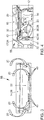
- Fig. 1 shows a motor vehicle trunk from diagonally above.
- the loading floor 14 which can be used by the user for depositing objects represents the lower limit of the trunk.
- Right and left side walls 15 delimit the trunk.
- the loading floor 14 is provided with a textile cover 36.
- Below the loading floor 14 is the here not shown trunk area for arrangement to be cooled units.
- Shown above right is the lock carrier rear 30, on which the lock is arranged to close the tailgate.
- This is a part of the motor vehicle body and firmly connected to the other shell components 34.
- a venting element 35 is arranged laterally, which is configured as an opening for discharging an air flow from the vehicle interior 55 into the environment of the vehicle; on the other hand, a similar venting element 35 is present.
- the trunk is bounded along the direction of travel 50 towards the front by the cover 22, which is also referred to as a bulkhead cover. Farther forward there are fasteners for the arrangement of the vehicle seats and intermediate lining parts.
- FIG. 2 the component system 10 according to the invention is shown in longitudinal section along the direction of travel 50.
- the loading floor 14 and the first component 16, which is a shell component, namely a bodyshell cross member, define the trunk area 12 in regions.
- a unit 32 to be cooled is shown schematically.
- air flow 20 air is passed to the unit 32 for the purpose of cooling.
- the passage 18 is arranged, through which an air flow 20 can be introduced into the trunk area 12.
- the trunk area 12 is lined with a flooring 28 located therein.
- the area of the floor covering 28 shown on the left is a panel 26 of the first component 16.
- a cavity 24 which is delimited in the direction of the vehicle interior 55 by a cover element 22.
- the cover member 22 covers the first component 16 such that the cavity 24 is formed.
- a first recess 40 In the lower region of the cover 22 is a first recess 40 through which the air flow 20 from the vehicle interior 55 into the cavity 24 can be passed.
- the cavity 24 is lined with a lining 26. It can be seen that the cover member 22 and the cover 26 between them form a second recess 41 through which the air flow 20 from the cavity 24 via the immediately behind the second recess 41 arranged passage 18 in the trunk area 12 can flow.
- the textile cover 36 of the loading floor is bent in its along the direction of travel 50 front area considered U-shaped around the loading floor 14 around and contacted there the cover 22nd Perpendicular to the image plane, a plurality of passages 18 are arranged distributed over the width of the motor vehicle, which passages are each separated from connecting regions in which there is a mechanical connection between first component 16 and loading floor 14.
- the first recess 40 of the cover 22 and the passage 18 are arranged so that they form an acoustic labyrinth.
- the first recess 40 and the passage 18 are arranged such that the sound located in the trunk area 12 must change direction twice before moving the vehicle interior 55 Thus, it is ensured that only a minimal proportion of the sound entered from outside into the trunk area 12 reaches the vehicle interior 55.
- the cavity 24 and / or the trunk area 12 may be lined with sound absorbing material 23.
- FIG. 3 shows the cover 22 from the front, so facing the direction of travel of the motor vehicle. It can be seen that a first recess 40 is arranged on the right and left outside. In addition, there are a number of first recesses 40 in the region of the lower edge. It is schematically illustrated how air flows 20 are led out of the vehicle interior 55 through the respective first recesses 40 into the cavity (not shown) located behind the cover element 22.
- the upper edge of the cover element 22 directly adjoins the loading floor 14 or the textile cover 36 arranged thereon.
- FIG. 4 shows the already in FIG. 2 illustrated embodiment of the component system according to the invention in a lateral view obliquely from above in the manner of an exploded view.
- the loading floor is not shown for clarity.
- the cover member 22 On the left side, seen in the direction of travel 50 represents the front portion of the component system, the cover member 22 is shown with the second recess 41 arranged thereon.
- a corresponding second recess 41 also referred to as franking 42, is arranged in the lining 26 covering the first component in the direction of the trunk area 12, namely the floor covering 28.
- said second recesses overlap 41 to form an opening through which the air flow 20 from the cavity 24 via the passage 18 (both not shown here) in the trunk area 12 can flow.
- a second component 17 is shown, which is part of the shell 34.
- a third recess 43 is arranged, by means of which in the trunk area 12 introduced air from this addition and can be derived.
- a flow channel located behind the second component 17 is a flow channel, with which the air flow shown by means of the straight arrow 20 against the direction of travel 50 to a rear-side vent element (not shown here) can be passed.
- the illustrated second component 17 limits the trunk area 12 on the right side of the vehicle.
- An analog equipped second component 17 is arranged correspondingly on the left side of the vehicle.
- the second components 17 serve for the lateral mechanical support of the loading floor.
- the trunk located above the loading floor is bounded laterally by the illustrated side wall 15.
- FIG. 5 shows a motor vehicle trunk from obliquely above by analogy FIG. 1 , Notwithstanding the embodiment shown there, a series of ventilation openings 45 is arranged here along the front edge of the loading floor 14.
- These can be provided as an alternative or in addition to the cover element 22 to be arranged in the first recesses 40 to air from the vehicle interior 55, namely from the user usable for storage of objects trunk directly into the cavity between the cover 22 and the first component (not here shown).
- FIG. 6 shows a further alternative embodiment, in which deviating from FIG. 3 between the cover 22 and the loading floor 14 and the textile cover 36 located thereon, a gap 44 is arranged.
- This serves as an alternative to the first recesses 40 which are not present here (cf. FIG. 3 ) and is adapted to guide located in the vehicle interior air in the located behind the cover 22 cavity.
- a gap 44 could also be provided in addition to at least one first recess 40.
Landscapes
- Engineering & Computer Science (AREA)
- Mechanical Engineering (AREA)
- Physics & Mathematics (AREA)
- Thermal Sciences (AREA)
- Cooling, Air Intake And Gas Exhaust, And Fuel Tank Arrangements In Propulsion Units (AREA)
- Body Structure For Vehicles (AREA)
- Vehicle Interior And Exterior Ornaments, Soundproofing, And Insulation (AREA)
- Arrangement Or Mounting Of Propulsion Units For Vehicles (AREA)
- Vehicle Step Arrangements And Article Storage (AREA)
Abstract
Description
- Die Erfindung betrifft ein Bauteilsystem zur Belüftung eines Kofferraumbereichs eines Kraftfahrzeugs zwecks Kühlung wenigstens einer in dem Kofferraumbereich befindlichen Einheit sowie ein Kraftfahrzeug, insbesondere einen Personenkraftwagen.
- In Kraftfahrzeugen werden vermehrt elektrische bzw. elektronische Einheiten angeordnet, die während der Nutzung Abwärme produzieren und die deshalb zur Gewährleistung eines dauerhaften störungsfreien Betriebs zu kühlen sind. Insbesondere im Bereich der Hybrid- und Elektrofahrzeuge sind zur Speicherung elektrischer Energie Superkondensatoren und/oder Sekundärbatterien vorhanden, die es zu kühlen gilt.
- Zu kühlende elektrische bzw. elektronische Einheiten können beispielsweise in einem unterhalb des Ladebodens des Kofferraums befindlichen Kofferraumbereich angeordnet sein. Eine bekannte Lösung zur Kühlung dort befindlicher Einheiten ist die Nutzung der im Kofferraum vorhandenen Luft. In Abhängigkeit der zur Kühlung der Einheiten erforderlichen Kühlleistung ist die vorhandene Luftmenge des Kofferraums allerdings nicht immer ausreichend.
- Zur Belüftung der zu kühlenden Einheiten kann Innenraumluft des Kraftfahrzeugs genutzt werden. Kraftfahrzeuge weisen typischerweise eine Zwangsentlüftung auf, die eine vom Nutzer nicht zu beeinflussende Verbindung des Fahrzeuginnenraums mit der Umgebung darstellt. Mittels dieser werden beispielsweise ungewünschte Luftdruckspitzen beim Schließen von Türen verhindert sowie eine Entlüftung des Fahrzeuginnenraums gewährleistet. Die im Folgenden beschriebenen Konzepte basieren auf der Nutzung von Luft aus dem Fahrzeuginnenraum, welche über die Zwangsentlüftung nach außen geführt wird.
- Die
DE 20 2007 006 995 U1 beschreibt eine Anordnung von Elektronikkomponenten in einem Fahrzeug, die eine Aufnahmevorrichtung für die Elektronikkomponenten in einem im Kofferraum des Fahrzeugs ausgebildeten seitlich angeordneten Stauraum umfasst. Der Stauraum befindet sich im Bereich der Zwangsentlüftung des Fahrzeugs und typischerweise hinter der Kofferraumverkleidung. Die Elektronikkomponente ist luftstromaufwärts im Abstand von einer Entlüftungsöffnung zur Zwangsentlüftung im Kofferraum angeordnet und kann vom Zwangsentlüftungsstrom im Fahrzeug umströmt werden. Somit fungiert der vorhandene Zwangsentlüftungsstrom zugleich als Kühlmittel für die Elektronikkomponenten. - Die
DE 10 2015 003 674 A1 offenbart eine Vorrichtung zur Entlüftung eines Fahrzeuginnenraums, bei der der Ladeboden eines Kofferraums mit mehreren, über die Ladebodenfläche verteilt angeordneten, Entlüftungsöffnungen versehen ist. Die Luft strömt durch diese in einen unter dem Ladeboden angeordneten Luftraum und anschließend über Auslässe im Heckabschlussblech nach außen. Der Luftraum kann beispielsweise eine muldenartige Vertiefung sein, wie sie beispielsweise zur Anordnung eines Ersatzrades bekannt ist. Die Entlüftungsöffnungen können durch eine Vielzahl von Löchern ausgebildet sein und/oder mit Abdeckungen versehen sein. - Es ist die Aufgabe der Erfindung, ein Bauteilsystem zur Belüftung eines Kofferraumbereichs und ein Kraftfahrzeug mit einem derartigen Bauteilsystem zur Verfügung zu stellen, mit welchen auf einfache, effektive und kostengünstige Weise die Kühlung wenigstens einer im Kofferraumbereich befindlichen Einheit möglich ist.
- Die Aufgabe wird gelöst durch das Bauteilsystem zur Belüftung eines Kofferraumbereichs gemäß Anspruch 1 sowie durch das Kraftfahrzeug gemäß Anspruch 9. Ausgestaltungen des Bauteilsystems sind in den Unteransprüchen 2-8 angegeben, eine Ausgestaltung des Kraftfahrzeugs ist in Unteranspruch 10 angegeben.
- Ein erster Aspekt der Erfindung ist ein Bauteilsystem zur Belüftung eines Kofferraumbereichs eines Kraftfahrzeugs zwecks Kühlung wenigstens einer in dem Kofferraumbereich befindlichen Einheit. Dieses umfasst einen Ladeboden zur Ablage von Gegenständen, den unter dem Ladeboden angeordneten Kofferraumbereich, sowie ein den Kofferraumbereich bereichsweise begrenzendes erstes Bauteil, insbesondere ein Rohbauteil. Zwischen Ladeboden und erstem Bauteil ist wenigstens ein Durchlass zur Durchleitung eines Luftstroms in den Kofferraumbereich angeordnet.
- Im Kofferraumbereich ist die wenigstens eine zu kühlende Einheit angeordnet. Insbesondere kann diese elektrische bzw. elektronische Komponenten umfassen, wie etwa Kondensatoren bzw. Superkondensatoren, auch als Supercaps bezeichnet, Sekundär-Batterien, Leistungselektronik, Steuerungs- und/oder Signalverarbeitungseinrichtungen, usw. Derartige Einheiten zeichnen sich häufig durch Wärmeentwicklung während des Betriebs bzw. der Nutzung aus, wobei diese Abwärme zur Gewährleistung eines stabilen und störungsfreien Betriebs abzuführen ist.
- Der Kofferraumbereich im Sinne der Erfindung ist bei bestimmungsgemäßem Gebrauch eines das Bauteilsystem aufweisenden Kraftfahrzeugs unterhalb des durch den Nutzer als Stauraum nutzbaren Kofferraums angeordnet. Typischerweise ist er von diesem separiert, insbesondere mittels des Ladebodens. Der Ladeboden ist somit der Boden des vom Nutzer nutzbaren Kofferraums. Auf diesem können Gegenstände abgelegt werden, etwa zum Transport in dem das Bauteilsystem aufweisenden Kraftfahrzeug. Der Ladeboden kann fest eingebaut bzw. einbaubar sein. Alternativ kann er als herausnehmbarer Einlegeboden ausgestaltet sein. Der Ladeboden kann aus mehreren Komponenten bzw. Schichten zusammengesetzt sein bzw. diese umfassen. Insbesondere begrenzt der Ladeboden den Kofferraumbereich bereichsweise.
- Das erste Bauteil begrenzt den Kofferraumbereich insbesondere in Richtung auf die Fahrzeugfront eines das Bauteilsystem aufweisenden Kraftfahrzeugs. Es bildet also eine vordere Begrenzung des Kofferraumbereichs aus. Es ist typischerweise länglich ausgebildet und quer zur Fahrtrichtung des Kraftfahrzeugs angeordnet. Begrenzen im Sinne der Erfindung meint, dass eine Form eines Bereichs des jeweiligen Raums, etwa des Kofferraumbereichs, zumindest im Wesentlichen durch das jeweilige Bauteil, etwa das erste Bauteil, definiert ist. Dabei können selbstverständlich weitere Bauteile wie Verkleidungen, Abdeckungen oder ähnliches im Kofferraumbereich angeordnet sein und das erste Bauteil in Richtung auf den Kofferraumbereich verkleiden.
- Das erste Bauteil kann ein Rohbauteil sein, also ein Teil der Fahrzeugkarosserie, wie beispielsweise ein Querträger bzw. ein Teil eines Querträgers. Es kann ein Blechbauteil sein.
- Der Durchlass bildet eine strömungstechnische Verbindung zwischen dem Kofferraumbereich und dem Innenraum des Kraftfahrzeugs. Er ist derart ausgestaltet, dass Luft aus dem Fahrzeuginnenraum durch ihn hindurch in den Kofferraumbereich strömen kann. Der Durchlass kann als Loch oder Spalt ausgeführt sein. Fahrzeuginnenraum meint dabei insbesondere den durch die innenliegenden Oberflächen des Kraftfahrzeugs begrenzten freien Raum im Kraftfahrzeug. Typischerweise ist eine Vielzahl von Durchlässen angeordnet. Insbesondere sind mehrere über die Längserstreckung des ersten Bauteils verteilt angeordnete Durchlässe angeordnet.
- Der Durchlass ist insbesondere derart zu dimensionieren, dass zumindest die zur Kühlung der angeordneten wenigstens einen zu kühlenden Einheit notwendige Luftmenge unter den Betriebsbedingungen bereitgestellt werden kann. Dabei sind die Temperaturen der zu kühlenden Einheit und der Luft im Fahrzeuginnenraum sowie die Strömungsbedingungen der Luft zu berücksichtigen.
- Der Durchlass befindet sich zumindest bereichsweise zwischen Ladeboden und erstem Bauteil. Mit anderen Worten ist seine Position als zwischen Ladeboden und erstem Bauteil befindlich definiert. Der Durchlass muss dabei nicht notwendigerweise durch eines oder beide der genannten Teile begrenzt oder ausgebildet sein. Er kann beispielsweise als Spalt zwischen Ladeboden und erstem Bauteil oder als Aussparung bzw. Öffnung im Ladeboden oder im ersten Bauteil realisiert sein.
- Mit anderen Worten sind der Ladeboden und das erste Bauteil derart ausgestaltet und/oder relativ zueinander positioniert, dass sich zwischen ihnen wenigstens ein Durchlass zur Durchleitung eines Luftstroms befindet. Der Ladeboden und/oder das erste Bauteil können im Bereich des Durchlasses selbstverständlich teilweise oder vollständig verkleidet sein.
- Die Durchleitung des Luftstroms erfolgt durch den Durchlass und in den Kofferraumbereich hinein. Insbesondere weist der Kofferraumbereich wenigstens eine weitere Öffnung zur Ableitung des Luftstroms auf. Diese kann an einer dem Durchlass benachbarten und/oder an einer diesem gegenüberliegenden Seite des Kofferraumbereichs angeordnet sein. Als eine derartige weitere Öffnung kann beispielsweise ein vorhandenes Entlüftungselement für die Zwangsentlüftung genutzt werden, welches in strömungstechnischer Verbindung mit dem Kofferraumbereich steht.
- Mit dem erfindungsgemäßen Bauteilsystem kann auf einfache, effektive und kostengünstige Weise die Kühlung wenigstens einer im Kofferraumbereich befindlichen Einheit realisiert werden. Weiterhin ist insbesondere im Sommer die Nutzung der gekühlten Luft aus dem Fahrzeuginnenraum zur Kühlung der Einheit vorteilhaft, da damit im Vergleich zur wärmeren Außenluft größere Wärmemengen aufgenommen werden können.
- In einer Ausgestaltung des Bauteilsystems dient das erste Bauteil zur mechanischen Abstützung des Ladebodens.
- Die Abstützung meint die zumindest anteilige Aufnahme von Kräften, insbesondere von Gewichtskräften, bei bestimmungsgemäßem Gebrauch entgegen der Schwerkraftrichtung.
- Das bedeutet, dass in zumindest einem Punkt bzw. einer Fläche ein direkter oder indirekter Kontakt zwischen dem ersten Bauteil und dem Ladeboden besteht, so dass es in zumindest diesem Punkt bzw. dieser Fläche zu einer mechanischen Abstützung des Ladebodens durch das erste Bauteil kommt. Dabei kann der Durchlass mit Blickrichtung von oben neben dieser Fläche angeordnet sein. Typischerweise sind mehrere zur Abstützung des Ladebodens eingerichtete Flächen angeordnet, zwischen denen sich jeweils Durchlässe zur Durchleitung jeweiliger Luftströme befinden.
- Insbesondere ist das erste Bauteil in dieser Ausführungsform ein Rohbauteil, sodass die Gewichtskraft des Ladebodens und/oder etwaig darauf angeordneter Gegenstände zumindest anteilig auf die Fahrzeugkarosserie übertragen werden kann. Das erste Bauteil kann ein Rohbau-Querträger sein, der der Bereitstellung der notwendigen Steifigkeit der Karosserie dient.
- Diese Ausgestaltung bringt den Vorteil mit sich, dass das zur Abstützung des Ladebodens notwendige erste Bauteil zugleich zur Realisierung des Durchlasses für den Luftstrom genutzt wird. Somit sind keine zusätzlichen Bauteile bzw. keine baulichen Veränderungen der vorhandenen Bauteile notwendig.
- In einer weiteren Ausgestaltung umfasst das Bauteilsystem weiterhin ein Abdeckelement zur Abdeckung des ersten Bauteils. Dieses ist derart angeordnet und/oder ausgestaltet, dass zwischen dem ersten Bauteil und dem Abdeckelement ein mit dem Kofferraumbereich strömungstechnisch verbundener Hohlraum ausgebildet ist. Die strömungstechnische Verbindung zwischen dem Kofferraumbereich und dem Hohlraum bildet der Durchlass.
- Der Hohlraum ist typischerweise luftstromaufwärts des Kofferraumbereichs befindlich. So kann der zu realisierende Luftstrom vom Fahrzeuginnenraum in den Hohlraum und von diesem in den Kofferraumbereich geleitet werden. Der Hohlraum kann ebenso wie der Kofferraumbereich zur Anordnung wenigstens einer zu kühlenden Einheit nutzbar sein. Insbesondere ist der Hohlraum entlang der Fahrtrichtung des Kraftfahrzeugs vor dem ersten Bauteil angeordnet. Er kann bereichsweise von diesem begrenzt sein. Das Abdeckelement kann den Hohlraum nach vorn und/oder oben gegenüber dem Fahrzeuginnenraum abgrenzen.
- Das Abdeckelement kann zur Abdeckung des ersten Bauteils in Richtung auf den Fahrzeuginnenraum des das Bauteilsystem aufweisenden Kraftfahrzeugs dienen. Es kann also als Sichtblende für das erste Bauteil und zur Unterbringung von elektrischen bzw. elektronischen Einheiten dienen. Typischerweise ist es als Kunststoffteil ausgeführt.
- Diese Ausgestaltung weist den Vorteil auf, dass mit dem Abdeckelement eine optisch ansprechende Sichtblende für das erste Bauteil zur Verfügung gestellt wird, die gleichermaßen als Funktionselement zur Realisierung des Luftstroms genutzt wird. Des Weiteren wird mit dem Hohlraum ein zusätzlicher nutzbarer Raum bereitgestellt. Durch den verlängerten Strömungspfad des Luftstroms wird eine deutliche Verringerung bzw. Dämmung des vom Kofferraumbereich ausgehenden Schalls erzielt.
- In einer weiteren Ausgestaltung weist das Abdeckelement wenigstens eine erste Aussparung zur Durchleitung des Luftstroms in den Hohlraum bzw. Kofferraumbereich auf. Alternativ oder zusätzlich ist zwischen Abdeckelement und Ladeboden ein Spalt zur Durchleitung des Luftstroms angeordnet.
- Die erste Aussparung kann ein beliebig geformtes Durchgangsloch oder eine an einem Rand des Abdeckelements angeordnete Aussparung sein. Es können mehrere erste Aussparungen angeordnet sein, die einander gleichen und/oder unterschiedlich ausgebildet sein können.
- Beispielsweise kann die erste Aussparung als Durchgangsloch im unteren Bereich des Abdeckelements realisiert sein. Auch können über die Breite des Abdeckelements, also über dessen quer zur Fahrtrichtung des Kraftfahrzeugs verlaufende Ausdehnungsrichtung, mehrere erste Aussparungen verteilt sein.
- Es können auch in den seitlichen Bereichen des Abdeckelements, also nahe seiner im Kraftfahrzeug rechts und links gelegenen seitlichen Begrenzungen, erste Aussparungen angeordnet sein.
- Diese Ausführungsform weist den Vorteil auf, dass die Strömungspfade des Luftstroms für die Belüftung des Hohlraums bzw. des Kofferraumbereichs länger sind und somit eine größere akustische Abschirmung bereitstellen. Des Weiteren sind die genannten Strömungspfade in Abhängigkeit der jeweiligen Anforderungen auf sehr variable Weise realisierbar, da eine Vielzahl von Möglichkeiten zur Anordnung und Ausgestaltung der Aussparungen existiert.
- Alternativ oder zusätzlich ist weiterhin eine Belüftung des Hohlraums durch Belüftungsöffnungen im Ladeboden möglich. In diesem Fall kann die Luft durch diese in den Hohlraum und von dort in bekannter Weise durch den Durchlass in den Kofferraumbereich strömen.
- Die strömungstechnische Verbindung zwischen dem Hohlraum und dem Kofferraumbereich kann eine von dem Abdeckelement und/oder einer Verkleidung des ersten Bauteils ausgebildete zweite Aussparung umfassen.
- In dieser Ausführungsform bildet bzw. weist das Abdeckelement und/oder eine Verkleidung des ersten Bauteils eine zweite Aussparung auf, die ein beliebig geformtes Durchgangsloch bzw. eine an einem Rand des Abdeckelements bzw. der Verkleidung angeordnete Aussparung sein kann. Es können mehrere zweite Aussparungen angeordnet, die einander gleichen und/oder unterschiedlich ausgebildet sein können. Die zweite Aussparung bildet einen Teil der strömungstechnischen Verbindung zwischen Hohlraum und Kofferraumbereich, ist also typischerweise nahe des Durchlasses angeordnet. Sie kann Teil des Durchlasses sein. Die Verkleidung des ersten Bauteils verkleidet dieses insbesondere in Bezug zum Hohlraum, zum Durchlass und/oder zum Kofferraumbereich.
- Das Abdeckelement kann beispielsweise entgegen der Fahrtrichtung des das Bauteilsystem aufweisenden Kraftfahrzeugs weiter nach hinten in Richtung auf den Kofferraumbereich erstreckt sein. Es kann in die Verkleidung des ersten Bauteils übergehen bzw. gemeinsam mit dieser ausgebildet sein. Mit anderen Worten kann der Hohlraum zumindest bereichsweise durch ein Bauteil begrenzt sein, welches als Verkleidung des ersten Bauteils gegenüber dem Hohlraum einerseits sowie als Abdeckelement andererseits fungiert, und in welchem wenigstens eine zweite Aussparung zur Durchleitung des Luftstroms in Strömungsrichtung auf den Kofferraumbereich angeordnet ist. Auch die Ausführung des Abdeckelements und der Verkleidung als separate Teile ist möglich, wobei die zweite Aussparung zwischen den beiden Bauteilen angeordnet sein kann. Das Abdeckelement und/oder die Verkleidung kann sich bis in den Bereich zwischen erstem Bauteil und Ladeboden erstrecken. In einer Ausführungsform ist der Hohlraum im Wesentlichen vollständig von einem Bauteil begrenzt, etwa einem Kunststoffteil, welches in seinem vorderen bzw. oberen Bereich als Abdeckelement zur Abdeckung des ersten Bauteils in Richtung auf den Fahrzeuginnenraum dient und somit den Hohlraum in Richtung auf den Fahrzeuginnenraum begrenzt und welches in seinem hinteren bzw. unteren Bereich eine Auskleidung des Hohlraums bildet und das erste Bauteil in Richtung auf den Hohlraum verkleidet. Alle Richtung- und Positionsangaben beziehen sich auf die bestimmungsgemäße Verwendung eines das Bauteilsystem aufweisenden Kraftfahrzeugs.
- Zusätzlich oder alternativ kann der Kofferraumbereich selbst teilweise oder vollständig mit einem Bodenbelag ausgekleidet sein. Dieser Bodenbelag kann als Absorbervlies zur Schalldämmung realisiert sein. Er kann derart ausgestaltet sein, dass er das erste Bauteil in Richtung auf den Kofferraumbereich verkleidet. Analog zum Abdeckelement kann auch der Bodenbelag einen Teil der strömungstechnischen Verbindung zwischen dem Hohlraum und im Kofferraumbereich ausbilden. Zu diesem Zweck kann er ebenfalls eine oder mehrere Aussparungen aufweisen, auch als Freimachung bezeichnet. In einer Ausgestaltung können der Bodenbelag des Kofferraumbereichs sowie die Verkleidung des Hohlraums miteinander verbunden sein bzw. ineinander übergehen, um das erste Bauteil vollständig zu verkleiden.
- Die beschriebene Ausführungsform weist den Vorteil auf, dass die strömungstechnische Verbindung zwischen dem Hohlraum und dem Kofferraumbereich auf besonders einfache Weise und unter Nutzung weniger Bauteile realisiert werden kann. Die Rohbauteile können derart verkleidet werden, dass sie für den Nutzer nicht sichtbar sind.
- In einer weiteren Ausgestaltung weist das Bauteilsystem wenigstens ein den Kofferraumbereich bereichsweise begrenzendes zweites Bauteil auf, wobei das zweite Bauteil zumindest eine dritte Aussparung, insbesondere eine Öffnung, zur Ableitung des Luftstroms aus dem Kofferraumbereich aufweist.
- Das zweite Bauteil ist insbesondere ein Rohbauteil, wie etwa ein Längsträger oder der hintere Schlossträger, und/oder dient zum seitlichen Abstützen des Ladebodens. Es kann eine seitliche und/oder hintere Begrenzung des Kofferraumbereichs sein. Es können mehrere zweite Bauteile angeordnet sein, die beispielsweise den Kofferraumbereich in unterschiedlichen Richtungen begrenzen. Typischerweise sind zwei zweite Bauteile auf einander gegenüberliegenden Seiten des Kofferraumbereichs angeordnet und begrenzen diesen beidseitig. Insbesondere hat jedes der zweiten Bauteile wenigstens eine dritte Aussparung.
- In dieser Ausgestaltung kann der Luftstrom durch den Durchlass von vorn in den Kofferraumbereich geleitet werden und seitlich, insbesondere beidseitig, aus dem Kofferraumbereich hinausgeleitet werden. Nach der Ableitung aus dem Kofferraumbereich durch die dritte Aussparung kann der Luftstrom außerhalb des Kofferraumbereichs hin zu einem Entlüftungselement für die Zwangsentlüftung geführt werden.
- Die dritte Aussparung kann ein beliebig geformtes Durchgangsloch oder wenigstens eine an einem Rand des dritten Bauteils angeordnete Aussparung sein. Wie jede Aussparung kann sie eine Abdeckung bzw. ein Gitter aufweisen, um den Durchtritt von Gegenständen zu verhindern. Die dritte Aussparung bildet die strömungstechnische Verbindung zwischen dem Kofferraumbereich und einem hinter dem zweiten Bauteil befindlichen Bereich, der etwa ein Strömungskanal zur Ableitung der Luft sein kann.
- Diese Ausgestaltung weist den Vorteil auf, dass auf einfache und kostengünstige Weise die Ableitung der zur Kühlung genutzten Luft realisiert werden kann. Weiterhin kann der Luftstrom durch geeignete Anordnung und Ausgestaltung der Durchlässe derart realisiert werden, dass eine besonders effiziente Wärmeübertragung möglich wird, beispielsweise durch geeignete Turbulenz.
- In einer weiteren Ausgestaltung weist das Bauteilsystem wenigstens ein mit dem Kofferraumbereich strömungstechnisch verbundenes Entlüftungselement zur Realisierung des Luftstroms durch den Kofferraumbereich auf. Dieses kann insbesondere ein Zwangsentlüfter sein.
- Das Entlüftungselement kann zur Ableitung des Luftstroms in die Umgebung des Kraftfahrzeugs dienen. Es kann zur Erzeugung eines Unterdrucks zum Ansaugen der Luft aus dem Fahrzeuginnenraum bzw. dem Hohlraum durch den Durchlass in den Kofferraumbereich eingerichtet sein und auf diese Weise zur Realisierung des Luftstroms geeignet sein.
- Das Entlüftungselement kann ein Zwangsentlüfter sein, also eine den Fahrzeuginnenraum mit der Fahrzeugumgebung verbindende Öffnung sein, die zur Zwangsentlüftung genutzt wird. Diese kann beispielsweise derart ausgestaltet sein, dass sie infolge der während der Fahrt des Kraftfahrzeugs auftretenden Luftströmung um das Kraftfahrzeug herum einen Unterdruck realisiert, der zur Entlüftung des Fahrzeuginnenraums geeignet ist.
- Das Entlüftungselement befindet sich luftstromabwärts vom Kofferraumbereich. Es kann bei Vorhandensein eines zweiten Bauteils mit dem hinter dem zweiten Bauteil befindlichen Bereich strömungstechnisch verbunden sein, so dass die Luft vom Kofferraumbereich durch die dritte Aussparung in den hinter dem zweiten Bauteil befindlichen Bereich geleitet werden kann, darin, insbesondere entgegen der Fahrtrichtung, nach hinten geführt werden kann und durch das Entlüftungselement in die Umgebung des Kraftfahrzeugs abgeleitet werden kann. Insbesondere können beidseitig Entlüftungselemente angeordnet sein.
- Das Entlüftungselement kann zur Ableitung des Luftstroms aus dem Kofferraumbereich eingerichtet sein.
- Diese Ausgestaltung bringt den Vorteil mit sich, dass der Luftstrom unter Nutzung der vorhandenen Entlüftungselemente für die Zwangsentlüftung realisiert bzw. erzeugt werden kann. Somit wird eine einfache und stabile Lösung ohne zusätzliche Teile zur Verfügung gestellt.
- Die erste Aussparung des Abdeckelements und der Durchlass können derart angeordnet sein, dass sie ein akustisches Labyrinth ausbilden.
- Ein akustisches Labyrinth meint eine Einrichtung zur Verhinderung einer geradlinigen Schallausbreitung bzw. zur Verringerung der akustischen Durchstrahlung. Dafür genutzte Mittel sind beispielsweise aufeinanderfolgende Umlenkungen und Querschnittsänderungen eines Querschnitts, in welchem Schall übertragen wird. Das akustische Labyrinth dient in Zusammenhang mit der Erfindung insbesondere der Verringerung des Anteils des im Kofferraumbereich befindlichen Schalls, der in den Fahrzeuginnenraum übertragen wird, und somit der Verringerung der Fahrgeräusche im Fahrzeuginnenraum. Der im Kofferraumbereich befindliche Schall wird in diesen insbesondere aus der äußeren Fahrzeugumgebung über den Rohbau und über Öffnungen, etwa durch Öffnungen für die Zwangsentlüftung, eingetragen.
- Zur Durchleitung des Luftstroms vom Fahrzeuginnenraum in den Hohlraum ist die erste Aussparung des Abdeckelements vorgesehen und zur Durchleitung des Luftstroms vom Hohlraum in den Kofferraumbereich ist der Durchlass vorgesehen. Um zu verhindern, dass Schall vom Kofferraumbereich geradlinig und somit weitgehend unvermindert in den Fahrzeuginnenraum gelangt, sind die erste Aussparung und der Durchlass in dieser Ausgestaltung derart angeordnet, dass der Schall, ausgehend von seinem Eintrittspunkt in den Kofferraumbereich, wenigstens einmal und insbesondere wenigstens zweimal die Richtung ändern muss, bevor er den Fahrzeuginnenraum erreicht. Damit wird trotz des Vorhandenseins einer strömungstechnischen Verbindung vom Fahrzeuginnenraum zur äußeren Umgebung des Kraftfahrzeugs eine wesentliche Abschwächung des Schalls und somit eine Geräuschminimierung im Fahrzeuginnenraum erreicht. Somit kann der Anteil des über die Zwangsentlüftung eingetragenen Schalls in den Fahrzeuginnenraum deutlich reduziert werden.
- Zusätzlich können der Kofferraumbereich und/oder der Hohlraum mit schallabsorbierenden Materialien ausgekleidet sein.
- Diese Ausgestaltung weist den Vorteil auf, dass trotz der vorhandenen und notwendigen Öffnung zur Entlüftung nach außen der eintretende Schall weitestgehend reduziert wird und somit die Geräusche im Fahrzeuginnenraum minimal gehalten werden können. Auch große Luftmengen können somit ohne störende Fahrgeräusche im Kofferraumbereich bereitgestellt werden.
- Ein zweiter Aspekt der Erfindung ist ein Kraftfahrzeug, insbesondere ein Personenkraftwagen. Dieses weist wenigstens ein erfindungsgemäßes Bauteilsystem zur Belüftung eines Kofferraumbereichs auf.
- Insbesondere ist der Durchlass zur Durchleitung eines im Wesentlichen entgegen der Fahrtrichtung des Kraftfahrzeugs gerichteten Luftstroms angeordnet, sodass Luft aus dem vorderen Teil des Fahrzeuginnenraums zur Kühlung der im Kofferraumbereich angeordneten Einheit genutzt werden kann.
- In einer Ausgestaltung des Kraftfahrzeugs weist dieses weiterhin wenigstens eine zu kühlende Einheit auf, insbesondere umfassend wenigstens einen Superkondensator. Diese ist derart im Kofferraumbereich angeordnet, dass sie mittels eines in den Kofferraumbereich eingeleiteten Luftstroms kühlbar ist.
- Eine zu kühlende Einheit ist ein Gegenstand, der gekühlt werden soll. Insbesondere ist es ein Gegenstand, der sich während seiner Nutzung erwärmt. Die dabei entstehende überschüssige Wärme wird abgeführt, um die Funktionalität der Einheit dauerhaft zu gewährleisten. Insbesondere sind, wie beschrieben, elektrische bzw. elektronische Einheiten gemeint, etwa Kondensatoren bzw. Superkondensatoren, auch als Supercaps bezeichnet, Sekundär-Batterien, Leistungselektronik, Steuerungs- und/oder Signalverarbeitungseinrichtungen, usw.
- Insbesondere wird der Luftstrom durch den Durchlass in den Kofferraumbereich eingeleitet. Typischerweise wird der Luftstrom an einer anderen Position, insbesondere mittels einer dritten Aussparung eines zweiten Bauteils, aus dem Kofferraum abgeleitet, sodass ein durchgehender Luftstrom zur Kühlung realisiert werden kann. Die Einheit ist insbesondere derart im Kofferraumbereich angeordnet, dass sie sich zwecks Realisierung einer effizienten Wärmeübertragung im zu erzeugenden Luftstrom befindet. Insbesondere ist der Luftstrom turbulent zu gestalten, um eine maximale Wärmeübertragung zu erzielen.
- Das Kraftfahrzeug kann alternativ oder zusätzlich zur zu kühlenden Einheit im Kofferraumbereich wenigstens eine zu kühlende Einheit im Hohlraum aufweisen.
- Ein weiterer Aspekt der Erfindung ist ein Verfahren zur Belüftung eines Kofferraumbereichs eines Kraftfahrzeugs zwecks Kühlung wenigstens einer in dem Kofferraumbereich befindlichen Einheit. Dabei wird durch einen Durchlass, welcher sich zwischen einem Ladeboden zur Ablage von Gegenständen und einem einen Kofferraumbereich des Kraftfahrzeugs bereichsweise begrenzenden ersten Bauteil, insbesondere einem Rohbauteil, ein Luftstrom durchgeleitet und zwecks Kühlung der darin befindlichen Einheit in den Kofferraumbereich eingeleitet.
- Insbesondere ist das Verfahren zur Durchführung mit dem erfindungsgemäßen Bauteilsystem und/oder dem erfindungsgemäßen Kraftfahrzeug realisierbar. In diesem Fall umfasst es neben der Bereitstellung des Bauteilsystems bzw. des Kraftfahrzeugs die Durchleitung eines Luftstroms durch den Durchlass in den Kofferraumbereich.
- Die Erfindung wird im Folgenden anhand der in den beiliegenden Zeichnungen dargestellten Ausführungsbeispiele erläutert.
- Es zeigen
-
Fig. 1 : eine perspektivische Ansicht eines Kraftfahrzeug-Kofferraums, -
Fig. 2 : einen Längsschnitt des erfindungsgemäßen Bauteilsystems in einer ersten Ausführungsform, -
Fig. 3 : eine perspektivische Ansicht des Abdeckelements ausFig. 2 , -
Fig. 4 : eine perspektivische seitliche Ansicht eines Kraftfahrzeug-Kofferraums mit dem erfindungsgemäßen Bauteilsystem, -
Fig. 5 : eine perspektivische Ansicht eines Kraftfahrzeug-Kofferraums mit einem entsprechend einer Ausgestaltung der Erfindung modifizierten Ladeboden, sowie -
Fig. 6 : eine Ansicht eines gemäß einer weiteren Ausgestaltung der Erfindung modifizierten Übergangs zwischen Ladeboden und Abdeckelement. -
Fig. 1 zeigt einen Kraftfahrzeug-Kofferraum von schräg oben. Der vom Nutzer zur Ablage von Gegenständen nutzbare Ladeboden 14 stellt die untere Begrenzung des Kofferraums dar. Rechts und links begrenzen Seitenwände 15 den Kofferraum. Der Ladeboden 14 ist mit einer textilen Abdeckung 36 versehen. Unterhalb des Ladebodens 14 befindet sich der hier nicht dargestellte Kofferraumbereich zur Anordnung zu kühlender Einheiten. Rechts oben dargestellt ist der Schlossträger hinten 30, an welchem das Schloss zum Schließen der Heckklappe angeordnet ist. Dieser ist ein Teil der Kraftfahrzeug-Karosserie und fest mit den weiteren Rohbauteilen 34 verbunden. Im Rohbau 34 ist seitlich ein Entlüftungselement 35 angeordnet, welches als Öffnung zur Ableitung eines Luftstroms aus dem Fahrzeuginnenraum 55 in die Umgebung des Fahrzeugs ausgestaltet ist; auf der anderen Seite ist ein gleichartiges Entlüftungselement 35 vorhanden. - Der Kofferraum wird entlang der Fahrtrichtung 50 nach vorne hin vom Abdeckelement 22 begrenzt, welches auch als Schottwandabdeckung bezeichnet wird. Weiter vorn befinden sich Befestigungselemente zur Anordnung der Fahrzeugsitze und dazwischen liegende Auskleidungsteile.
- In
Figur 2 ist das erfindungsgemäße Bauteilsystem 10 im Längsschnitt entlang der Fahrtrichtung 50 dargestellt. Es ist ersichtlich, dass der Ladeboden 14 und das erste Bauteil 16, welches ein Rohbauteil ist, nämlich ein Rohbau-Querträger, den Kofferraumbereich 12 bereichsweise begrenzen. Im Kofferraumbereich 12 ist eine zu kühlende Einheit 32 schematisch dargestellt. Mittels des Luftstroms 20 wird zwecks Kühlung Luft an der Einheit 32 vorbei geleitet. Zwischen dem Ladeboden 14 und dem ersten Bauteil 16 ist der Durchlass 18 angeordnet, durch welchen ein Luftstrom 20 in den Kofferraumbereich 12 eingeleitet werden kann. - Der Kofferraumbereich 12 ist mit einem darin befindlichen Bodenbelag 28 ausgekleidet. Der links dargestellte Bereich des Bodenbelags 28 ist dabei eine Verkleidung 26 des ersten Bauteils 16.
- Links vom ersten Bauteil 16, also luftstromaufwärts des Durchlasses 18, befindet sich ein Hohlraum 24, welcher in Richtung auf den Fahrzeuginnenraum 55 von einem Abdeckelement 22 begrenzt wird. Das Abdeckelement 22 deckt das erste Bauteil 16 derart ab, dass der Hohlraum 24 ausgebildet wird. Im unteren Bereich des Abdeckelements 22 befindet sich eine erste Aussparung 40, durch welche der Luftstrom 20 vom Fahrzeuginnenraum 55 in den Hohlraum 24 geleitet werden kann.
- Auf der Seite des ersten Bauteils 16 ist der Hohlraum 24 mit einer Verkleidung 26 ausgekleidet. Es ist ersichtlich, dass das Abdeckelement 22 und die Verkleidung 26 zwischen einander eine zweite Aussparung 41 ausbilden, durch welche der Luftstrom 20 vom Hohlraum 24 über den unmittelbar hinter der zweiten Aussparung 41 angeordneten Durchlass 18 in den Kofferraumbereich 12 strömen kann. Die textile Abdeckung 36 des Ladebodens ist in dessen entlang der Fahrtrichtung 50 betrachteten vorderem Bereich U-förmig um den Ladeboden 14 herum gebogen und kontaktiert dort das Abdeckelement 22. Das erste Bauteil 16 dient der mechanischen Abstützung des Ladebodens 14. Senkrecht zur Bildebene sind über die Breite des Kraftfahrzeugs verteilt mehrere Durchlässe 18 angeordnet, welche jeweils von Verbindungsbereichen separiert sind, in welchen eine mechanische Verbindung zwischen erstem Bauteil 16 und Ladeboden 14 besteht.
- Weiterhin ist ersichtlich, dass die erste Aussparung 40 des Abdeckelements 22 sowie der Durchlass 18 derart angeordnet sind, dass sie ein akustisches Labyrinth ausbilden. Um zu verhindern, dass Schall vom Kofferraumbereich 12 geradlinig und somit weitgehend unvermindert in den Fahrzeuginnenraum 55 gelangt, sind die erste Aussparung 40 und der Durchlass 18 derart angeordnet, dass der im Kofferraumbereich 12 befindliche Schall zweimal die Richtung ändern muss, bevor er den Fahrzeuginnenraum 55 erreicht, nämlich einmal im Bereich des Durchlasses 18 und ein weiteres Mal im Inneren des Hohlraums 24. Somit wird sichergestellt, dass nur ein minimaler Anteil des von außen in den Kofferraumbereich 12 eingetragenen Schalls in den Fahrzeuginnenraum 55 gelangt.
- Zusätzlich können der Hohlraum 24 und/oder der Kofferraumbereich 12 mit schallabsorbierendem Material 23 ausgekleidet sein.
-
Figur 3 zeigt das Abdeckelement 22 von vorn, also mit Blickrichtung entgegen der Fahrtrichtung des Kraftfahrzeugs. Es ist ersichtlich, dass rechts und links außen jeweils eine erste Aussparung 40 angeordnet ist. Zusätzlich befindet sich eine Reihe erster Aussparungen 40 im Bereich der Unterkante. Schematisch ist dargestellt, wie Luftströme 20 aus dem Fahrzeuginnenraum 55 durch die jeweiligen ersten Aussparungen 40 in den hinter dem Abdeckelement 22 befindlichen, nicht dargestellten Hohlraum geleitet werden. - Wie bereits aus
Figur 2 ersichtlich, schließt die Oberkante des Abdeckelements 22 unmittelbar an den Ladeboden 14 bzw. an die daran angeordnete textile Abdeckung 36 an. -
Figur 4 zeigt die bereits inFigur 2 dargestellte Ausgestaltung des erfindungsgemäßen Bauteilsystems in einer seitlichen Ansicht von schräg oben nach Art einer Explosionszeichnung. Der Ladeboden ist zur Steigerung der Übersichtlichkeit nicht dargestellt. - Auf der linken Seite, die in Fahrtrichtung 50 gesehen den vorderen Bereich des Bauteilsystems darstellt, ist das Abdeckelement 22 mit der daran angeordneten zweiten Aussparung 41 dargestellt. Eine entsprechende zweite Aussparung 41, auch als Freimachung 42 bezeichnet, ist in der das erste Bauteil in Richtung auf den Kofferraumbereich 12 abdeckenden Verkleidung 26, nämlich dem Bodenbelag 28, angeordnet. Im montierten Zustand überlappen sich die genannten zweiten Aussparungen 41 unter Ausbildung einer Öffnung, durch welche der Luftstrom 20 vom Hohlraum 24 über den Durchlass 18 (beide hier nicht gezeigt) in den Kofferraumbereich 12 strömen kann.
- Oberhalb des Kofferraumbereichs 12 mit der darin angeordneten zu kühlenden Einheit 32 ist ein zweites Bauteil 17 dargestellt, welches Teil des Rohbaus 34 ist. In diesem ist eine dritte Aussparung 43 angeordnet, mittels welcher in den Kofferraumbereich 12 eingeleitete Luft aus diesem hinaus und abgeleitet werden kann. Zu diesem Zweck befindet sich hinter dem zweiten Bauteil 17 ein Strömungskanal, mit welchem der mittels des geraden Pfeils dargestellte Luftstrom 20 entgegen der Fahrtrichtung 50 zu einem heckseitig befindlichen Entlüftungselement (hier nicht dargestellt) geleitet werden kann.
- Das dargestellte zweite Bauteil 17 begrenzt den Kofferraumbereich 12 auf der rechten Fahrzeugseite. Ein analog ausgestattetes zweites Bauteil 17 ist entsprechend an der linken Fahrzeugseite angeordnet. Die zweiten Bauteile 17 dienen der seitlichen mechanischen Abstützung des Ladebodens. Der oberhalb des Ladebodens befindliche Kofferraum ist seitlich von der dargestellten Seitenwand 15 begrenzt.
-
Figur 5 zeigt einen Kraftfahrzeug-Kofferraum von schräg oben analog zuFigur 1 . Abweichend von der dort gezeigten Ausgestaltung ist hier entlang der vorderen Kante des Ladebodens 14 eine Reihe von Belüftungsöffnungen 45 angeordnet. Diese können alternativ oder zusätzlich zu den im Abdeckelement 22 anzuordnenden ersten Aussparungen 40 vorgesehen werden, um Luft aus dem Fahrzeuginnenraum 55, nämlich aus dem vom Nutzer zur Ablage von Gegenständen nutzbaren Kofferraum, direkt in den zwischen Abdeckelement 22 und erstem Bauteil befindlichen Hohlraum (hier nicht dargestellt) zu leiten. -
Figur 6 zeigt eine weitere alternative Ausgestaltung, bei welcher abweichend zuFigur 3 zwischen dem Abdeckelement 22 und dem Ladeboden 14 bzw. der daran befindlichen textilen Abdeckung 36 ein Spalt 44 angeordnet ist. Dieser dient als Alternative zu den hier nicht vorhandenen ersten Aussparungen 40 (vergleicheFigur 3 ) und ist dazu eingerichtet, im Fahrzeuginnenraum befindliche Luft in den hinter dem Abdeckelement 22 befindlichen Hohlraum zu leiten. Selbstverständlich könnte ein derartiger Spalt 44 auch zusätzlich zu wenigstens einer ersten Aussparung 40 vorgesehen werden.Bezugszeichenliste Bauteilsystem 10 Kofferraumbereich 12 Ladeboden 14 Seitenwand 15 Erstes Bauteil 16 Zweites Bauteil 17 Durchlass 18 Luftstrom 20 Abdeckelement 22 Schallabsorbierendes Material 23 Hohlraum 24 Verkleidung 26 Bodenbelag 28 Schlossträger hinten 30 Zu kühlende Einheit 32 Rohbau 34 Entlüftungselement 35 Textile Abdeckung 36 Erste Aussparung 40 Zweite Aussparung 41 Freimachung 42 Dritte Aussparung 43 Spalt 44 Belüftungsöffnung 45 Fahrtrichtung 50 Fahrzeuginnenraum 55
Claims (10)
- Bauteilsystem (10) zur Belüftung eines Kofferraumbereichs (12) eines Kraftfahrzeugs zwecks Kühlung wenigstens einer in dem Kofferraumbereich (12) befindlichen Einheit (32), umfassend einen Ladeboden (14) zur Ablage von Gegenständen, den unter dem Ladeboden (14) angeordneten Kofferraumbereich (12), sowie ein den Kofferraumbereich (12) bereichsweise begrenzendes erstes Bauteil (16), insbesondere ein Rohbauteil,
dadurch gekennzeichnet, dass zwischen Ladeboden (14) und erstem Bauteil (16) wenigstens ein Durchlass (18) zur Durchleitung eines Luftstroms (20) in den Kofferraumbereich (12) angeordnet ist. - Bauteilsystem (10) zur Belüftung eines Kofferraumbereichs (12) nach Anspruch 1, dadurch gekennzeichnet, dass das erste Bauteil (16) zur mechanischen Abstützung des Ladebodens (14) dient.
- Bauteilsystem (10) zur Belüftung eines Kofferraumbereichs (12) nach einem der vorhergehenden Ansprüche, dadurch gekennzeichnet, dass das Bauteilsystem (10) weiterhin ein Abdeckelement (22) zur Abdeckung des ersten Bauteils (16) umfasst, wobei das Abdeckelement (22) derart angeordnet und/oder ausgestaltet ist, dass zwischen dem ersten Bauteil (16) und dem Abdeckelement (22) ein mit dem Kofferraumbereich (12) strömungstechnisch verbundener Hohlraum (24) ausgebildet ist.
- Bauteilsystem (10) zur Belüftung eines Kofferraumbereichs (12) nach Anspruch 3, dadurch gekennzeichnet, dass das Abdeckelement (22) wenigstens eine erste Aussparung (40) zur Durchleitung des Luftstroms (20) in den Hohlraum (24) aufweist und/oder dass zwischen Abdeckelement (22) und Ladeboden (14) ein Spalt (44) zur Durchleitung des Luftstroms (20) in den Hohlraum (24) angeordnet ist.
- Bauteilsystem (10) zur Belüftung eines Kofferraumbereichs (12) nach einem der Ansprüche 3 und 4, dadurch gekennzeichnet, dass die strömungstechnische Verbindung zwischen dem Hohlraum (24) und dem Kofferraumbereich (12) eine von dem Abdeckelement (22) und/oder einer Verkleidung (26) des ersten Bauteils (16) ausgebildete zweite Aussparung (41) umfasst.
- Bauteilsystem (10) zur Belüftung eines Kofferraumbereichs (12) nach einem der vorhergehenden Ansprüche, dadurch gekennzeichnet, dass das Bauteilsystem (10) wenigstens ein den Kofferraumbereich (12) bereichsweise begrenzendes zweites Bauteil (17) aufweist, wobei das zweite Bauteil (17) zumindest eine dritte Aussparung (43), insbesondere eine Öffnung, zur Ableitung des Luftstroms (20) aus dem Kofferraumbereich (12) aufweist.
- Bauteilsystem (10) zur Belüftung eines Kofferraumbereichs (12) nach einem der vorhergehenden Ansprüche, dadurch gekennzeichnet, dass das Bauteilsystem (10) wenigstens ein mit dem Kofferraumbereich (12) strömungstechnisch verbundenes Entlüftungselement (35), insbesondere einen Zwangsentlüfter, zur Realisierung des Luftstroms (20) durch den Kofferraumbereich (12) aufweist.
- Bauteilsystem (10) zur Belüftung eines Kofferraumbereichs (12) nach einem der Ansprüche 4-7, dadurch gekennzeichnet, dass die erste Aussparung (40) des Abdeckelements (22) und der Durchlass (18) derart angeordnet sind, dass sie ein akustisches Labyrinth ausbilden.
- Kraftfahrzeug, insbesondere Personenkraftwagen, dadurch gekennzeichnet, dass das Kraftfahrzeug wenigstens ein Bauteilsystem (10) zur Belüftung eines Kofferraumbereichs (12) gemäß einem der Ansprüche 1-8 aufweist.
- Kraftfahrzeug nach Anspruch 9, dadurch gekennzeichnet, dass das Kraftfahrzeug weiterhin wenigstens eine zu kühlende Einheit (32) aufweist, insbesondere umfassend wenigstens einen Superkondensator, wobei die wenigstens eine Einheit (32) derart im Kofferraumbereich (12) angeordnet ist, dass sie mittels eines in den Kofferraumbereich (12) eingeleiteten Luftstroms (20) kühlbar ist.
Applications Claiming Priority (1)
| Application Number | Priority Date | Filing Date | Title |
|---|---|---|---|
| DE102017123698.8A DE102017123698B4 (de) | 2017-10-11 | 2017-10-11 | Bauteilsystem zur Belüftung eines Kofferraumbereichs und Kraftfahrzeug |
Publications (2)
| Publication Number | Publication Date |
|---|---|
| EP3470249A1 true EP3470249A1 (de) | 2019-04-17 |
| EP3470249B1 EP3470249B1 (de) | 2020-03-04 |
Family
ID=63794400
Family Applications (1)
| Application Number | Title | Priority Date | Filing Date |
|---|---|---|---|
| EP18199161.3A Active EP3470249B1 (de) | 2017-10-11 | 2018-10-08 | Bauteilsystem zur belüftung eines kofferraumbereichs und kraftfahrzeug |
Country Status (5)
| Country | Link |
|---|---|
| US (1) | US10913329B2 (de) |
| EP (1) | EP3470249B1 (de) |
| JP (1) | JP6856602B2 (de) |
| CN (1) | CN109649113B (de) |
| DE (1) | DE102017123698B4 (de) |
Families Citing this family (8)
| Publication number | Priority date | Publication date | Assignee | Title |
|---|---|---|---|---|
| DE102017123698B4 (de) * | 2017-10-11 | 2019-10-02 | Dr. Ing. H.C. F. Porsche Ag | Bauteilsystem zur Belüftung eines Kofferraumbereichs und Kraftfahrzeug |
| US11548352B2 (en) * | 2018-10-12 | 2023-01-10 | Fca Us Llc | Interior trim storage bin/tray with integrated exhauster path |
| US11634062B1 (en) * | 2020-04-14 | 2023-04-25 | Matthew MacGregor Roy | Vehicle having divisible trunk for separately heating and cooling divided trunk compartments based on object recognition |
| WO2022099503A1 (zh) * | 2020-11-11 | 2022-05-19 | 深圳元戎启行科技有限公司 | 自动驾驶车辆 |
| CN113251691A (zh) * | 2021-06-18 | 2021-08-13 | 北京百度网讯科技有限公司 | 制冷设备及车辆 |
| DE102021004515A1 (de) | 2021-09-07 | 2023-03-09 | Mercedes-Benz Group AG | Kraftfahrzeug mit einer Fahrzeugkabine und einer Kabinenentlüftungsvorrichtung sowie Verfahren zum Abführen von Abluft aus einer Fahrzeugkabine |
| CN116572849A (zh) * | 2023-06-27 | 2023-08-11 | 浙江极氪智能科技有限公司 | 车辆的储物机构及车辆 |
| DE102024103922A1 (de) | 2024-02-13 | 2025-08-14 | Bayerische Motoren Werke Aktiengesellschaft | Kraftfahrzeug mit temperierbarem Kofferraumboden |
Citations (5)
| Publication number | Priority date | Publication date | Assignee | Title |
|---|---|---|---|---|
| JPH0260006U (de) * | 1988-10-26 | 1990-05-02 | ||
| JP2005075082A (ja) * | 2003-08-29 | 2005-03-24 | Suzuki Motor Corp | 車両の換気構造 |
| DE202008002920U1 (de) * | 2008-02-29 | 2008-05-29 | GM Global Technology Operations, Inc., Detroit | Temperierbares Ladestaufach |
| US20090008060A1 (en) * | 2007-07-05 | 2009-01-08 | Robinet Kevin J | Watertight Vehicle Airduct System |
| DE102009055835A1 (de) * | 2009-11-26 | 2011-06-01 | GM Global Technology Operations LLC, ( n. d. Ges. d. Staates Delaware ), Detroit | Aufbewahrungsvorrichtung zur Anordnung innerhalb eines Kraftfahrzeuges |
Family Cites Families (26)
| Publication number | Priority date | Publication date | Assignee | Title |
|---|---|---|---|---|
| US5392873A (en) * | 1992-01-22 | 1995-02-28 | Honda Giken Kogyo Kabushiki Kaisha | Structure for securing batteries used in an electric vehicle |
| JP3509517B2 (ja) * | 1997-12-18 | 2004-03-22 | 本田技研工業株式会社 | 電気自動車におけるバッテリおよび電気部品の冷却構造 |
| JP3777981B2 (ja) * | 2000-04-13 | 2006-05-24 | トヨタ自動車株式会社 | 車両用電源装置 |
| JP3973147B2 (ja) * | 2002-07-09 | 2007-09-12 | 本田技研工業株式会社 | 冷却装置の配置構造 |
| US6899366B2 (en) * | 2003-10-23 | 2005-05-31 | Daimlerchrysler Corporation | Vehicle storage and ventilation system |
| DE102004020930B4 (de) * | 2004-04-28 | 2007-05-24 | Adam Opel Ag | Ablage im Innenraum eines Kraftfahrzeugs |
| JP4385020B2 (ja) * | 2005-06-02 | 2009-12-16 | 本田技研工業株式会社 | 車両用電源装置 |
| JP4673692B2 (ja) * | 2005-07-19 | 2011-04-20 | 本田技研工業株式会社 | 車両における電気機器の冷却構造 |
| EP1897739B1 (de) * | 2006-09-07 | 2010-11-03 | Honda Motor Co., Ltd. | Kühlstruktur einer elektrischen Vorrichtung in einem Fahrzeug |
| JP4337905B2 (ja) * | 2007-04-18 | 2009-09-30 | トヨタ自動車株式会社 | 車両に搭載された電気機器の冷却装置 |
| DE202007006995U1 (de) | 2007-05-15 | 2007-07-26 | Volkswagen Ag | Anordnung von Elektronikkomponenten in einem Fahrzeug |
| US8186468B2 (en) * | 2008-02-19 | 2012-05-29 | GM Global Technology Operations LLC | Vehicle load floor support with integral air duct |
| US8276696B2 (en) * | 2010-07-27 | 2012-10-02 | Ford Global Technologies, Llc | Structural battery duct assembly |
| JP5473954B2 (ja) * | 2011-01-14 | 2014-04-16 | 本田技研工業株式会社 | 冷却構造を有する高電圧機器装置、及びそれを備えた車両 |
| EP3520995B1 (de) * | 2011-06-29 | 2021-10-13 | Kyoraku Co., Ltd. | Form zur herstellung einer harzlaminierten platte |
| DE102012020683A1 (de) * | 2012-10-22 | 2014-04-24 | Volkswagen Aktiengesellschaft | Anordnung zur Vermeidung von Schallimmission in den Innenraum eines Fahrzeugs und Fahrzeug mit einer solchen Anordnung |
| DE102012110451A1 (de) * | 2012-10-31 | 2014-04-30 | Dr. Ing. H.C. F. Porsche Aktiengesellschaft | Innenraumentlüftung |
| US8808827B2 (en) * | 2012-11-27 | 2014-08-19 | Global Ip Holdings, Llc | Cargo management system including a vehicle load floor having a vehicle component restraining feature |
| JP5827615B2 (ja) * | 2012-12-27 | 2015-12-02 | トヨタ紡織株式会社 | 車両用排気構造 |
| US10399450B2 (en) * | 2014-09-14 | 2019-09-03 | Electric Motor Werks, Inc. | Systems and methods for local autonomous response to grid conditions by electric vehicle charging stationsas and other similar loads |
| JP6303030B2 (ja) * | 2015-02-05 | 2018-03-28 | 本田技研工業株式会社 | 車両のバッテリ冷却構造 |
| DE102015003674A1 (de) | 2015-03-20 | 2015-12-03 | Audi Ag | Vorrichtung zur Entlüftung eines Fahrzeuginnenraums |
| US9457737B1 (en) * | 2015-03-27 | 2016-10-04 | Nissan North America, Inc. | Vehicle noise reducing assembly |
| US20190263558A1 (en) * | 2016-07-18 | 2019-08-29 | Plant IP Pty Ltd | A blow-molded panel for a storage container |
| DE102017123698B4 (de) * | 2017-10-11 | 2019-10-02 | Dr. Ing. H.C. F. Porsche Ag | Bauteilsystem zur Belüftung eines Kofferraumbereichs und Kraftfahrzeug |
| JP6958223B2 (ja) * | 2017-10-20 | 2021-11-02 | トヨタ自動車株式会社 | 電気自動車 |
-
2017
- 2017-10-11 DE DE102017123698.8A patent/DE102017123698B4/de not_active Expired - Fee Related
-
2018
- 2018-10-08 EP EP18199161.3A patent/EP3470249B1/de active Active
- 2018-10-10 JP JP2018191798A patent/JP6856602B2/ja active Active
- 2018-10-11 US US16/157,762 patent/US10913329B2/en active Active
- 2018-10-11 CN CN201811182617.4A patent/CN109649113B/zh active Active
Patent Citations (5)
| Publication number | Priority date | Publication date | Assignee | Title |
|---|---|---|---|---|
| JPH0260006U (de) * | 1988-10-26 | 1990-05-02 | ||
| JP2005075082A (ja) * | 2003-08-29 | 2005-03-24 | Suzuki Motor Corp | 車両の換気構造 |
| US20090008060A1 (en) * | 2007-07-05 | 2009-01-08 | Robinet Kevin J | Watertight Vehicle Airduct System |
| DE202008002920U1 (de) * | 2008-02-29 | 2008-05-29 | GM Global Technology Operations, Inc., Detroit | Temperierbares Ladestaufach |
| DE102009055835A1 (de) * | 2009-11-26 | 2011-06-01 | GM Global Technology Operations LLC, ( n. d. Ges. d. Staates Delaware ), Detroit | Aufbewahrungsvorrichtung zur Anordnung innerhalb eines Kraftfahrzeuges |
Also Published As
| Publication number | Publication date |
|---|---|
| DE102017123698B4 (de) | 2019-10-02 |
| CN109649113B (zh) | 2022-07-12 |
| JP6856602B2 (ja) | 2021-04-07 |
| EP3470249B1 (de) | 2020-03-04 |
| DE102017123698A1 (de) | 2019-04-11 |
| US10913329B2 (en) | 2021-02-09 |
| JP2019073273A (ja) | 2019-05-16 |
| CN109649113A (zh) | 2019-04-19 |
| US20190105966A1 (en) | 2019-04-11 |
Similar Documents
| Publication | Publication Date | Title |
|---|---|---|
| DE102017123698B4 (de) | Bauteilsystem zur Belüftung eines Kofferraumbereichs und Kraftfahrzeug | |
| EP3080519B1 (de) | Schallabsorbierendes element für einen luftausströmer | |
| DE112014004618B4 (de) | Fortbewegungsmittel mit Brennstoffzelle | |
| DE102011118412B4 (de) | Kühlkanalstruktur für eine Batterieeinheit | |
| DE102014201675B4 (de) | Befestigungsanordnung für eine elektrische baugruppe eines fahrzeugs | |
| DE102004043237B4 (de) | Frischlufteinlass eines Fahrzeuges | |
| DE102009027475A1 (de) | Luftführungsvorrichtung | |
| DE102017004964A1 (de) | Karosserieteil für ein Fahrzeug und Fahrzeug mit einem solchen Karosserieteil | |
| WO2015010866A1 (de) | Schienenfahrzeugwagen | |
| DE102016219485A1 (de) | Kraftfahrzeug und Energiespeichereinrichtung | |
| DE102008060410B4 (de) | Kraftfahrzeug mit Schwellerblende | |
| DE102014221156A1 (de) | Kraftfahrzeug mit einem innerhalb der Karosserie gelegenen Aggregateraum | |
| DE102011118148A1 (de) | Luftausströmeranordnung | |
| DE102012102933B4 (de) | Vorrichtung für ein Frontendmodul eines Fahrzeuges zur Einstellung einer Kühlluftzuströmung zu einem Kühlmodul des Fahrzeuges sowie Frontendmodul eines Fahrzeuges | |
| DE202016101418U1 (de) | Integrierter NVH-Entkoppler und Frontalaufprallstrebe | |
| DE102008045596B4 (de) | Vorrichtung und Verfahren zum Kühlen einer Abgasanlage eines Kraftwagens | |
| EP2402574A1 (de) | Kühlluftführungssystem für ein Fahrzeug | |
| DE102015210271A1 (de) | Trolleyfach und Bordküche | |
| DE102018202131B4 (de) | Komponente für ein Kraftfahrzeug und Kraftfahrzeug | |
| DE102007023230A1 (de) | Luftführungseinrichtung an einem Personenkraftwagen | |
| DE102016222150B4 (de) | Anordnung und Verfahren zur Zuführung von Belüftungsluft zu einer Belüftungseinrichtung für einen Fahrzeuginnenraum sowie Kraftfahrzeug | |
| DE102021101511B4 (de) | Elektrofahrzeug | |
| DE102006026098A1 (de) | Kraftfahrzeug | |
| DE102017215522A1 (de) | System zum Kühlen eines Aggregats | |
| DE102024135949B3 (de) | Kofferraumanordnung für einen Vorderwagen mit Lüftern für hohen Luftdurchsatz durch Wärmeübertrager und Kraftfahrzeug |
Legal Events
| Date | Code | Title | Description |
|---|---|---|---|
| PUAI | Public reference made under article 153(3) epc to a published international application that has entered the european phase |
Free format text: ORIGINAL CODE: 0009012 |
|
| STAA | Information on the status of an ep patent application or granted ep patent |
Free format text: STATUS: THE APPLICATION HAS BEEN PUBLISHED |
|
| AK | Designated contracting states |
Kind code of ref document: A1 Designated state(s): AL AT BE BG CH CY CZ DE DK EE ES FI FR GB GR HR HU IE IS IT LI LT LU LV MC MK MT NL NO PL PT RO RS SE SI SK SM TR |
|
| AX | Request for extension of the european patent |
Extension state: BA ME |
|
| STAA | Information on the status of an ep patent application or granted ep patent |
Free format text: STATUS: REQUEST FOR EXAMINATION WAS MADE |
|
| 17P | Request for examination filed |
Effective date: 20190617 |
|
| RBV | Designated contracting states (corrected) |
Designated state(s): AL AT BE BG CH CY CZ DE DK EE ES FI FR GB GR HR HU IE IS IT LI LT LU LV MC MK MT NL NO PL PT RO RS SE SI SK SM TR |
|
| GRAP | Despatch of communication of intention to grant a patent |
Free format text: ORIGINAL CODE: EPIDOSNIGR1 |
|
| STAA | Information on the status of an ep patent application or granted ep patent |
Free format text: STATUS: GRANT OF PATENT IS INTENDED |
|
| RIC1 | Information provided on ipc code assigned before grant |
Ipc: B60H 1/00 20060101AFI20191024BHEP Ipc: B60R 5/04 20060101ALI20191024BHEP Ipc: B60H 1/24 20060101ALI20191024BHEP Ipc: B60H 1/26 20060101ALI20191024BHEP |
|
| INTG | Intention to grant announced |
Effective date: 20191121 |
|
| GRAS | Grant fee paid |
Free format text: ORIGINAL CODE: EPIDOSNIGR3 |
|
| GRAA | (expected) grant |
Free format text: ORIGINAL CODE: 0009210 |
|
| STAA | Information on the status of an ep patent application or granted ep patent |
Free format text: STATUS: THE PATENT HAS BEEN GRANTED |
|
| AK | Designated contracting states |
Kind code of ref document: B1 Designated state(s): AL AT BE BG CH CY CZ DE DK EE ES FI FR GB GR HR HU IE IS IT LI LT LU LV MC MK MT NL NO PL PT RO RS SE SI SK SM TR |
|
| REG | Reference to a national code |
Ref country code: GB Ref legal event code: FG4D Free format text: NOT ENGLISH |
|
| REG | Reference to a national code |
Ref country code: CH Ref legal event code: EP |
|
| REG | Reference to a national code |
Ref country code: AT Ref legal event code: REF Ref document number: 1239964 Country of ref document: AT Kind code of ref document: T Effective date: 20200315 |
|
| REG | Reference to a national code |
Ref country code: DE Ref legal event code: R096 Ref document number: 502018000885 Country of ref document: DE |
|
| REG | Reference to a national code |
Ref country code: IE Ref legal event code: FG4D Free format text: LANGUAGE OF EP DOCUMENT: GERMAN |
|
| REG | Reference to a national code |
Ref country code: DE Ref legal event code: R082 Ref document number: 502018000885 Country of ref document: DE Representative=s name: SCHULZ JUNGHANS PATENTANWAELTE PARTGMBB, DE |
|
| PG25 | Lapsed in a contracting state [announced via postgrant information from national office to epo] |
Ref country code: RS Free format text: LAPSE BECAUSE OF FAILURE TO SUBMIT A TRANSLATION OF THE DESCRIPTION OR TO PAY THE FEE WITHIN THE PRESCRIBED TIME-LIMIT Effective date: 20200304 Ref country code: FI Free format text: LAPSE BECAUSE OF FAILURE TO SUBMIT A TRANSLATION OF THE DESCRIPTION OR TO PAY THE FEE WITHIN THE PRESCRIBED TIME-LIMIT Effective date: 20200304 Ref country code: NO Free format text: LAPSE BECAUSE OF FAILURE TO SUBMIT A TRANSLATION OF THE DESCRIPTION OR TO PAY THE FEE WITHIN THE PRESCRIBED TIME-LIMIT Effective date: 20200604 |
|
| REG | Reference to a national code |
Ref country code: NL Ref legal event code: MP Effective date: 20200304 |
|
| PG25 | Lapsed in a contracting state [announced via postgrant information from national office to epo] |
Ref country code: SE Free format text: LAPSE BECAUSE OF FAILURE TO SUBMIT A TRANSLATION OF THE DESCRIPTION OR TO PAY THE FEE WITHIN THE PRESCRIBED TIME-LIMIT Effective date: 20200304 Ref country code: LV Free format text: LAPSE BECAUSE OF FAILURE TO SUBMIT A TRANSLATION OF THE DESCRIPTION OR TO PAY THE FEE WITHIN THE PRESCRIBED TIME-LIMIT Effective date: 20200304 Ref country code: BG Free format text: LAPSE BECAUSE OF FAILURE TO SUBMIT A TRANSLATION OF THE DESCRIPTION OR TO PAY THE FEE WITHIN THE PRESCRIBED TIME-LIMIT Effective date: 20200604 Ref country code: GR Free format text: LAPSE BECAUSE OF FAILURE TO SUBMIT A TRANSLATION OF THE DESCRIPTION OR TO PAY THE FEE WITHIN THE PRESCRIBED TIME-LIMIT Effective date: 20200605 Ref country code: HR Free format text: LAPSE BECAUSE OF FAILURE TO SUBMIT A TRANSLATION OF THE DESCRIPTION OR TO PAY THE FEE WITHIN THE PRESCRIBED TIME-LIMIT Effective date: 20200304 |
|
| REG | Reference to a national code |
Ref country code: LT Ref legal event code: MG4D |
|
| PG25 | Lapsed in a contracting state [announced via postgrant information from national office to epo] |
Ref country code: NL Free format text: LAPSE BECAUSE OF FAILURE TO SUBMIT A TRANSLATION OF THE DESCRIPTION OR TO PAY THE FEE WITHIN THE PRESCRIBED TIME-LIMIT Effective date: 20200304 |
|
| PG25 | Lapsed in a contracting state [announced via postgrant information from national office to epo] |
Ref country code: SM Free format text: LAPSE BECAUSE OF FAILURE TO SUBMIT A TRANSLATION OF THE DESCRIPTION OR TO PAY THE FEE WITHIN THE PRESCRIBED TIME-LIMIT Effective date: 20200304 Ref country code: EE Free format text: LAPSE BECAUSE OF FAILURE TO SUBMIT A TRANSLATION OF THE DESCRIPTION OR TO PAY THE FEE WITHIN THE PRESCRIBED TIME-LIMIT Effective date: 20200304 Ref country code: LT Free format text: LAPSE BECAUSE OF FAILURE TO SUBMIT A TRANSLATION OF THE DESCRIPTION OR TO PAY THE FEE WITHIN THE PRESCRIBED TIME-LIMIT Effective date: 20200304 Ref country code: SK Free format text: LAPSE BECAUSE OF FAILURE TO SUBMIT A TRANSLATION OF THE DESCRIPTION OR TO PAY THE FEE WITHIN THE PRESCRIBED TIME-LIMIT Effective date: 20200304 Ref country code: IS Free format text: LAPSE BECAUSE OF FAILURE TO SUBMIT A TRANSLATION OF THE DESCRIPTION OR TO PAY THE FEE WITHIN THE PRESCRIBED TIME-LIMIT Effective date: 20200704 Ref country code: PT Free format text: LAPSE BECAUSE OF FAILURE TO SUBMIT A TRANSLATION OF THE DESCRIPTION OR TO PAY THE FEE WITHIN THE PRESCRIBED TIME-LIMIT Effective date: 20200729 Ref country code: ES Free format text: LAPSE BECAUSE OF FAILURE TO SUBMIT A TRANSLATION OF THE DESCRIPTION OR TO PAY THE FEE WITHIN THE PRESCRIBED TIME-LIMIT Effective date: 20200304 Ref country code: RO Free format text: LAPSE BECAUSE OF FAILURE TO SUBMIT A TRANSLATION OF THE DESCRIPTION OR TO PAY THE FEE WITHIN THE PRESCRIBED TIME-LIMIT Effective date: 20200304 Ref country code: CZ Free format text: LAPSE BECAUSE OF FAILURE TO SUBMIT A TRANSLATION OF THE DESCRIPTION OR TO PAY THE FEE WITHIN THE PRESCRIBED TIME-LIMIT Effective date: 20200304 |
|
| REG | Reference to a national code |
Ref country code: DE Ref legal event code: R097 Ref document number: 502018000885 Country of ref document: DE |
|
| PLBE | No opposition filed within time limit |
Free format text: ORIGINAL CODE: 0009261 |
|
| STAA | Information on the status of an ep patent application or granted ep patent |
Free format text: STATUS: NO OPPOSITION FILED WITHIN TIME LIMIT |
|
| PG25 | Lapsed in a contracting state [announced via postgrant information from national office to epo] |
Ref country code: IT Free format text: LAPSE BECAUSE OF FAILURE TO SUBMIT A TRANSLATION OF THE DESCRIPTION OR TO PAY THE FEE WITHIN THE PRESCRIBED TIME-LIMIT Effective date: 20200304 Ref country code: DK Free format text: LAPSE BECAUSE OF FAILURE TO SUBMIT A TRANSLATION OF THE DESCRIPTION OR TO PAY THE FEE WITHIN THE PRESCRIBED TIME-LIMIT Effective date: 20200304 |
|
| 26N | No opposition filed |
Effective date: 20201207 |
|
| PG25 | Lapsed in a contracting state [announced via postgrant information from national office to epo] |
Ref country code: SI Free format text: LAPSE BECAUSE OF FAILURE TO SUBMIT A TRANSLATION OF THE DESCRIPTION OR TO PAY THE FEE WITHIN THE PRESCRIBED TIME-LIMIT Effective date: 20200304 Ref country code: PL Free format text: LAPSE BECAUSE OF FAILURE TO SUBMIT A TRANSLATION OF THE DESCRIPTION OR TO PAY THE FEE WITHIN THE PRESCRIBED TIME-LIMIT Effective date: 20200304 |
|
| PG25 | Lapsed in a contracting state [announced via postgrant information from national office to epo] |
Ref country code: LU Free format text: LAPSE BECAUSE OF NON-PAYMENT OF DUE FEES Effective date: 20201008 Ref country code: MC Free format text: LAPSE BECAUSE OF FAILURE TO SUBMIT A TRANSLATION OF THE DESCRIPTION OR TO PAY THE FEE WITHIN THE PRESCRIBED TIME-LIMIT Effective date: 20200304 |
|
| REG | Reference to a national code |
Ref country code: BE Ref legal event code: MM Effective date: 20201031 |
|
| PG25 | Lapsed in a contracting state [announced via postgrant information from national office to epo] |
Ref country code: BE Free format text: LAPSE BECAUSE OF NON-PAYMENT OF DUE FEES Effective date: 20201031 |
|
| PG25 | Lapsed in a contracting state [announced via postgrant information from national office to epo] |
Ref country code: IE Free format text: LAPSE BECAUSE OF NON-PAYMENT OF DUE FEES Effective date: 20201008 |
|
| REG | Reference to a national code |
Ref country code: CH Ref legal event code: PL |
|
| PG25 | Lapsed in a contracting state [announced via postgrant information from national office to epo] |
Ref country code: TR Free format text: LAPSE BECAUSE OF FAILURE TO SUBMIT A TRANSLATION OF THE DESCRIPTION OR TO PAY THE FEE WITHIN THE PRESCRIBED TIME-LIMIT Effective date: 20200304 Ref country code: MT Free format text: LAPSE BECAUSE OF FAILURE TO SUBMIT A TRANSLATION OF THE DESCRIPTION OR TO PAY THE FEE WITHIN THE PRESCRIBED TIME-LIMIT Effective date: 20200304 Ref country code: CY Free format text: LAPSE BECAUSE OF FAILURE TO SUBMIT A TRANSLATION OF THE DESCRIPTION OR TO PAY THE FEE WITHIN THE PRESCRIBED TIME-LIMIT Effective date: 20200304 |
|
| PG25 | Lapsed in a contracting state [announced via postgrant information from national office to epo] |
Ref country code: MK Free format text: LAPSE BECAUSE OF FAILURE TO SUBMIT A TRANSLATION OF THE DESCRIPTION OR TO PAY THE FEE WITHIN THE PRESCRIBED TIME-LIMIT Effective date: 20200304 Ref country code: AL Free format text: LAPSE BECAUSE OF FAILURE TO SUBMIT A TRANSLATION OF THE DESCRIPTION OR TO PAY THE FEE WITHIN THE PRESCRIBED TIME-LIMIT Effective date: 20200304 |
|
| PG25 | Lapsed in a contracting state [announced via postgrant information from national office to epo] |
Ref country code: LI Free format text: LAPSE BECAUSE OF NON-PAYMENT OF DUE FEES Effective date: 20211031 Ref country code: CH Free format text: LAPSE BECAUSE OF NON-PAYMENT OF DUE FEES Effective date: 20211031 |
|
| P01 | Opt-out of the competence of the unified patent court (upc) registered |
Effective date: 20230526 |
|
| REG | Reference to a national code |
Ref country code: AT Ref legal event code: MM01 Ref document number: 1239964 Country of ref document: AT Kind code of ref document: T Effective date: 20231008 |
|
| PGFP | Annual fee paid to national office [announced via postgrant information from national office to epo] |
Ref country code: GB Payment date: 20241121 Year of fee payment: 7 |
|
| PG25 | Lapsed in a contracting state [announced via postgrant information from national office to epo] |
Ref country code: AT Free format text: LAPSE BECAUSE OF NON-PAYMENT OF DUE FEES Effective date: 20231008 |
|
| PGFP | Annual fee paid to national office [announced via postgrant information from national office to epo] |
Ref country code: FR Payment date: 20241031 Year of fee payment: 7 |
|
| PG25 | Lapsed in a contracting state [announced via postgrant information from national office to epo] |
Ref country code: AT Free format text: LAPSE BECAUSE OF NON-PAYMENT OF DUE FEES Effective date: 20231008 |
|
| PGFP | Annual fee paid to national office [announced via postgrant information from national office to epo] |
Ref country code: DE Payment date: 20251020 Year of fee payment: 8 |
|
| PGFP | Annual fee paid to national office [announced via postgrant information from national office to epo] |
Ref country code: AT Payment date: 20260410 Year of fee payment: 5 |