EP3460168A1 - Verzögerungseinheit, schnurträger und horizontale jalousie - Google Patents
Verzögerungseinheit, schnurträger und horizontale jalousie Download PDFInfo
- Publication number
- EP3460168A1 EP3460168A1 EP17799307.8A EP17799307A EP3460168A1 EP 3460168 A1 EP3460168 A1 EP 3460168A1 EP 17799307 A EP17799307 A EP 17799307A EP 3460168 A1 EP3460168 A1 EP 3460168A1
- Authority
- EP
- European Patent Office
- Prior art keywords
- cord
- rotation
- drive shaft
- winding
- delay unit
- Prior art date
- Legal status (The legal status is an assumption and is not a legal conclusion. Google has not performed a legal analysis and makes no representation as to the accuracy of the status listed.)
- Withdrawn
Links
Images









Classifications
-
- E—FIXED CONSTRUCTIONS
- E06—DOORS, WINDOWS, SHUTTERS, OR ROLLER BLINDS IN GENERAL; LADDERS
- E06B—FIXED OR MOVABLE CLOSURES FOR OPENINGS IN BUILDINGS, VEHICLES, FENCES OR LIKE ENCLOSURES IN GENERAL, e.g. DOORS, WINDOWS, BLINDS, GATES
- E06B9/00—Screening or protective devices for wall or similar openings, with or without operating or securing mechanisms; Closures of similar construction
- E06B9/24—Screens or other constructions affording protection against light, especially against sunshine; Similar screens for privacy or appearance; Slat blinds
- E06B9/26—Lamellar or like blinds, e.g. venetian blinds
- E06B9/28—Lamellar or like blinds, e.g. venetian blinds with horizontal lamellae, e.g. non-liftable
- E06B9/30—Lamellar or like blinds, e.g. venetian blinds with horizontal lamellae, e.g. non-liftable liftable
- E06B9/303—Lamellar or like blinds, e.g. venetian blinds with horizontal lamellae, e.g. non-liftable liftable with ladder-tape
- E06B9/308—Lamellar or like blinds, e.g. venetian blinds with horizontal lamellae, e.g. non-liftable liftable with ladder-tape with coaxial tilting bar and raising shaft
-
- E—FIXED CONSTRUCTIONS
- E06—DOORS, WINDOWS, SHUTTERS, OR ROLLER BLINDS IN GENERAL; LADDERS
- E06B—FIXED OR MOVABLE CLOSURES FOR OPENINGS IN BUILDINGS, VEHICLES, FENCES OR LIKE ENCLOSURES IN GENERAL, e.g. DOORS, WINDOWS, BLINDS, GATES
- E06B9/00—Screening or protective devices for wall or similar openings, with or without operating or securing mechanisms; Closures of similar construction
- E06B9/24—Screens or other constructions affording protection against light, especially against sunshine; Similar screens for privacy or appearance; Slat blinds
- E06B9/26—Lamellar or like blinds, e.g. venetian blinds
- E06B9/28—Lamellar or like blinds, e.g. venetian blinds with horizontal lamellae, e.g. non-liftable
- E06B9/30—Lamellar or like blinds, e.g. venetian blinds with horizontal lamellae, e.g. non-liftable liftable
- E06B9/32—Operating, guiding, or securing devices therefor
- E06B9/322—Details of operating devices, e.g. pulleys, brakes, spring drums, drives
Definitions
- the present invention relates to a delay unit of a cord support member allowing operation of raising, lowering, and tilting slats with one drive shaft, a cord support device thereof, and a Venetian blind including them.
- Venetian blinds are capable of adjusting an amount of solar radiation to be taken indoor by raising, lowering, and tilting a number of slats supported by ladder cords hung from a head box using a lift cord.
- a bottom rail is arranged at the lower end of ladder cords and a lift cord attached to the bottom rail is pulled in a head box and pulled out of the head box to raise and lower the bottom rail, thereby allowing raising and lowering of the number of slats.
- Venetian blind As a type of such a Venetian blind, those are generally known that use a cord support member allowing operation, with one drive shaft, of rotation of a tilt drum hangingly supporting ladder cords and a winding shaft windably or unwindably hangingly supporting a lift cord.
- a cord support member has a tilt drum and a winding shaft engaged in the respective projections with a clearance to delay rotation of the winding shaft relative to rotation of the tilt drum (e.g., refer to PTL 1).
- a tilt drum (rotary tilt drum) is directly coupled to rotate with rotation of the drive shaft and a shaft member (bushing) is newly provided to be fixed to the cord support member.
- the shaft member has one end provided with a brake drum and a clutch ring and is arranged between the tilt drum and a winding shaft (lift drum).
- the winding shaft is idlably hooked on a cylindrical periphery of the shaft member protruding from the brake drum and engaged with the tilt drum in the respective projections to rotate together with a 180-degree clearance. Accordingly, the winding shaft is not directly coupled with the drive shaft and the rotation of the winding shaft is provided with some clearance relative to the rotation of the tilt drum to allow delay of the rotation of the winding shaft.
- the ladder cord is hung on the tilt drum with the upper end portion of the ladder cord in an annular shape, whereby the ladder cord is suspended, and the slat supported by the weft of the ladder cord is rotated by the rotation of the tilt drum There is something to move.
- this cord supporting device it is necessary to generate a predetermined frictional resistance between the tilt drum and the annular upper end portion of the ladder cord in order to transmit the rotation of the tilt drum to the movement of the ladder cord. For this reason, there is known a technique of providing a friction member on a part of the annular upper end portion of the ladder cord (see, for example, Patent Document 2).
- a general cord support member allowing operation of rotating a tilt drum and a winding shaft with one drive shaft has operability problems of raising and lowering of a bottom rail due to tilting operation even when the tilting operation is desired not to cause raising and lowering of slats and of raising of stacked slats before tilting during tilting operation when the bottom rail is not in a lower limit position.
- the technique in PTL 1 is capable of solving the problems, whereas the technique in PTL 1 has a configuration of, to delay the rotation of the winding shaft relative to the rotation of the tilt drum, engaging the tilt drum and the winding shaft in the respective projections with a clearance. Accordingly, for providing a plurality of cord support members in a head box and the like, positioning (slat angle adjustment, cord length adjustment, etc.) of the cord support members relative to one drive shaft is assumed to require assembly of the cord support members over and over again while relative positional relationship between the tilt drum and the winding shaft is adjusted every time and there is thus a concern of assemblability to the head box.
- the technique in PTL 1 also has a configuration that the winding shaft is idlably hooked on a cylindrical periphery of the shaft member, causing difficulty in miniaturization. Due to an increase in the diameter of the entire cord support members, there is a concern of an increase in costs of the cord support members or the Venetian blind.
- the technique in PTL 1 only discloses a configuration having a delay angle of 180 degrees, which is required to change the shape of at least the tilt drum, the winding shaft, and the clutch ring for application to the angle of other than 180 degrees.
- Cord support members respectively with a tilt drum, a winding shaft, and a clutch ring changed in shape have to be prepared for each application of Venetian blinds, resulting in an increase in costs.
- PTL 1 The technique in PTL 1 is also considered to replace the entire cord support members even when a delay angle is intended to be adjusted or altered during assembly. There is thus a concern of an increase in operations and expenses for parts control.
- a technique that allows operation of rotating a tilt drum and a winding shaft of slats with one drive shaft, solves the problem of raising and lowering of a bottom rail due to tilting operation even when the tilting operation is desired not to cause raising and lowering of slats and the problem of raising of stacked slats before tilting during tilting operation when the bottom rail is not in a lower limit position, improves assemblability, and is excellent in practicality contributing to miniaturization, versatility, reduction of operations and expenses for parts control, and inexpensiveness.
- Another object of the present invention is to provide a lateral blind in which a frictional resistance relating to a latch is adapted to a cord supporting apparatus having a tilt drum configured to hook an upper end portion of an annular rudder cord is there.
- a delay unit of the present invention is a delay unit for a cord support device allowing operation of raising, lowering, and tilting of slats with one drive shaft, wherein the delay unit is provided so as to be aligned to one drive shaft outside or inside a support case, the support case rotatably supports a tilt drum and a winding shaft, respectively, with the drive shaft as an axis of rotation of the tilt drum and the winding shaft, and the delay unit is configured so that the winding shaft is rotated with a predetermined delay along with rotation of the tilt drum.
- the cord support device of the present invention includes the delay unit.
- a cord support device of the present invention is a cord support device allowing operation of raising, lowering, and tilting of slats with one drive shaft, including:
- the delay unit is configured to link rotation transmission sections to produce the predetermined delay in an axial direction of the drive shaft.
- the delay unit is configured to link rotation transmission sections to produce the predetermined delay in a vertical direction to the drive shaft.
- the delay unit includes:
- the brake member includes:
- the cord support device of the present invention further includes a rotation relay plate to relay rotation with a predetermined delay between the input shaft member and the output shaft member, allowing change of a delay due to the engagement of the input shaft member with the output shaft member.
- the case member of the delay unit is formed by fitting a plurality of members in a vertical direction to the drive shaft.
- the delay unit is arranged to be coupled with a bearing of the winding shaft through an obstacle detecting and stopping device.
- an amount of rotation to produce a delay by the delay unit is set as an angular adjustment range of the slats or more.
- a case member of the delay unit has a nail, the nail holding the support case of the cord support device or a support auxiliary member of the winding shaft.
- an output stem of the delay unit has a locking mechanism to be directly or indirectly coupled with a bearing of the winding shaft.
- a Venetian blind of the present invention includes the cord support device of the present invention.
- a Venetian blind of the present invention allowing operation of raising and lowering of slats by winding or unwinding a lift cord with a plurality of winding shafts configuring a cord winding device based on rotation of one drive shaft, hanging ladder cords from a plurality of tilt drums, and rotating the tilt drums based on the rotation of the drive shaft to allow angular adjustment of the slats supported by the ladder cords, wherein the blind is configured to, when the slats are flipped after the operation of raising and lowering of the slats, transmit the rotation of the drive shaft to the tilt drums, prevent rotation of the winding shafts during angular adjustment of the slats, and cause the winding shafts to rotate along with rotation of the drive shaft after predetermined relative rotation, and by providing a brake mechanism, separately from the cord winding device, nonrotatably supported to a head box storing the cord winding device and the tilt drums, configured to prevent the rotation of the winding shafts during the ang
- a Venetian blind of the present invention allowing operation of raising and lowering of slats by winding or unwinding a lift cord with a plurality of winding shafts configuring a cord winding device based on rotation of one drive shaft, hanging ladder cords from a plurality of tilt drums, and rotating the ladder cords based on the rotation of the drive shaft to allow angular adjustment of the slats supported by the ladder cords
- the blind includes a plurality of delay units aligned respectively to the winding shafts on the drive shaft to cause the winding shafts to rotate with a predetermined delay along with relative to rotation of the tilt drums, wherein each of the delay units has a shape allowing, during assembly to a head box to store the winding shafts and the tilt drums, insertion from an opening provided in an upper surface of the head box without deforming the head box.
- a Venetian blind of the present invention allowing operation of raising and lowering of slats by winding or unwinding a lift cord with a plurality of winding shafts configuring a cord winding device based on rotation of one drive shaft, hanging ladder cords from a plurality of tilt drums, and rotating the ladder cords based on the rotation of the drive shaft to allow angular adjustment of the slats supported by the ladder cords
- the blind includes a plurality of delay units aligned respectively to the winding shafts on the drive shaft to cause the winding shafts to rotate with a predetermined delay along with rotation of the tilt drums, wherein the winding shafts and the tilt drums are stored in a head box, the head box having an upper surface opened with a first length in a fore and aft direction and an inside having a storage space with a second length greater than the first length, each of the delay units has a shape to inhibit, during assembly to the head box, shifting in a fore and aft direction and
- a Venetian blind of the present invention allowing operation of raising and lowering of slats by winding or unwinding a lift cord with a plurality of winding shafts configuring a cord winding device based on rotation of one drive shaft, hanging ladder cords from a plurality of tilt drums, and rotating the ladder cords based on the rotation of the drive shaft to allow angular adjustment of the slats supported by the ladder cords
- the blind includes a plurality of delay units aligned respectively to the winding shafts on the drive shaft to cause the winding shafts to rotate with a predetermined delay along with rotation of the tilt drums, wherein the respective delay units are, during assembly to a head box to store the winding shafts and the tilt drums, separated relative to the winding shafts to allow initialization of the respective delay units by arbitrarily inserting the drive shaft into an axial center of the delay units, the winding shafts, and the tilt drums, followed by arbitrary rotation in a predetermined number of rotation or more and to allow positioning
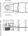
- a horizontal blind according to another aspect of the present invention is a horizontal blind that allows a ladder cord to follow and rotate a slat by rotation of a tilt drum, and includes a plurality of annular ridges for a pair of indoor and outdoor ladder cords And a cord supporting device configured to be hung on the outer peripheral surface formed on the tilt drum with a predetermined frictional force.
- the upper end of the rudder cord depending on the interior side is engaged with the ladder cord hanging from the interior side to the outer circumferential surface of the tilt drum and then to the outdoor side
- the upper end of the ladder cord hanging out to the outside of the chamber is engaged with a ladder cord hanging from the outdoor side to the outer circumferential surface of the tilt drum and then hanging down to the interior side.
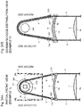
- the upper end of the rudder cord depending on the interior side is engaged with the ladder cord hanging from the interior side to the outer circumferential surface of the tilt drum and then to the outdoor side ,
- the upper end of the ladder cord hanging out to the outside of the room is hung from the outdoor side to the outer peripheral surface of the tilt drum and then distributed along the uppermost weft provided between the pair of ladder cords, And is engaged with a ladder cord hanging to the outside.
- the upper end of the rudder cord depending on the interior side is subjected to the first engagement from the interior side to the outer circumferential surface of the tilt drum, and then the pair of ladder cords A second lath on the outer circumferential surface of the ladder hanging down to the outdoor side, and a ladder hanging down to the outside of the chamber
- the upper end of the cord is engaged with a cord portion at the time of the first engagement of the ladder cord hanging down to the indoor side.
- the upper end locking portions of the pair of indoor side and outdoor side ladder cords are provided on the outdoor side.
- the present invention allows operation of rotating a tilt drum and a winding shaft with one drive shaft, solves the problem of raising and lowering of a bottom rail due to tilting operation even when the tilting operation is desired not to cause raising and lowering of slats and, in particular, the problem of raising of stacked slats before tilting during tilting operation when the bottom rail is not in a lower limit position, improves assemblability, and is excellent in practicality contributing to miniaturization, versatility, reduction of operations and expenses for parts control, and inexpensiveness.
- a description as an example is given below to a Venetian blind allowing rotation of one drive shaft to operate raising and lowering of slats by a lift cord and tilting of slats by ladder cords.
- an upper part and a lower part of the drawing are defined respectively as an upward direction (or an upper side) and a downward direction (or a lower side) with respect to the slat hanging direction
- a left direction and a right direction of the drawing are defined respectively as a left side and a right side of the Venetian blind.
- a front side or an indoor side
- the opposite side as a rear side (or an outdoor side)
- a fore and aft direction of the Venetian blind means a direction vertical to an illustrated side of the front view in Fig. 1 .
- Fig. 1 is a front view illustrating a schematic configuration of a Venetian blind in one embodiment of the present invention.
- the Venetian blind illustrated in Fig. 1 has a head box 1 is provided inside with a cord support device 5 configured to align a delay unit 5a according to the present invention to a cord support unit 5b and the head box 1 has a ladder cord support member 6 arranged inside on a right end side.
- a cord support device 5 configured to align a delay unit 5a according to the present invention to a cord support unit 5b
- the head box 1 has a ladder cord support member 6 arranged inside on a right end side.
- only one cord support device 5 and only one ladder cord support member 6 are shown while two or more cord support devices 5 and cord support members 6 may be provided in the head box 1.
- the cord support unit 5b and the ladder cord support member 6 hangingly support a number of slats 4 via a pair of string-like ladder cords 9 hanging down respectively to the indoor side and the outdoor side, and the respective ladder cords 9 hangingly support a bottom rail 8 at a lower end of them.
- the head box 1 is fixed to a mount surface on the ceiling side via brackets 7.
- a string-like lift cord 10 is hung at the approximate center in a fore and aft direction on a lower surface of the head box 1, and the lift cord 10 has a lower end attached to the bottom rail 8 via through holes, not shown, provided at the approximate center in a fore and aft direction of the slats 4.
- the cord support unit 5b is thus configured to align a tilt drum 51 having a V groove to be laid with the pair of ladder cords 9 hanging down respectively to the indoor side and the outdoor side and a cylindrical winding shaft 52 inclined to allow winding or unwinding of the lift cord 10 on a square-rod drive shaft 11 to be supported by a support case 50.
- an obstacle detecting and stopping device 53 is provided on a tip end side of the winding shaft 52.
- the obstacle detecting and stopping device 53 is a device to prevent rotation of the winding shaft 52 supporting the lift cord 10 when no tension in a pull-out direction is exerted on the lift cord 10 and has a function of, when the bottom rail 8 collides with an obstacle during lowering of the slats 4, discontinuing unwinding of the lift cord 10, stopping lowering of the slats 4 and the bottom rail 8, and preventing reverse winding of the lift cord 10.
- the cord support unit 5b is configured to have the tilt drum 51 relatively nonrotatably coupled with the drive shaft 11 in contrast to the winding shaft 52 supported by the support case 50 not to be coupled (not engaged) with the drive shaft 11, and the delay unit 5a to actuate the winding shaft 52 to rotate with a predetermined delay along with rotation of the tilt drum 51 is aligned on the drive shaft 11 to the cord support unit 5b.
- the ladder cord support member 6 is a device simply supporting the tilt drum 51a having a V groove to be laid with the pair of ladder cords 9 hanging down respectively to the indoor side and the outdoor side.
- the head box 1 is provided with an operation unit 2 on a right end side.
- the operation unit 2 of a manually operated type as illustrated has a pulley, not shown, capable of being laid with an endless string-like operation cord 3 (or may be an endless ball chain) and the operation cord 3 is led outward from the head box 1 to be capable of operation of rotating the drive shaft 11.
- the operation unit 2 of an electrically operated type may be an electric motor capable of operation of rotating the drive shaft 11 based on an operating signal from outside.
- the operation unit 2 may thus be in an arbitrary form as long as the form allows transmission to rotation of the drive shaft 11 in accordance with operation by an operator.
- the Venetian blind illustrated in Fig. 1 is thus capable of tilting operation to adjust the angle of the slats 4 by rotation of the drive shaft 11 by operating the operation cord 3 and rotation of, with the rotation of the drive shaft 11, the tilt drum 51 in the cord support device 5 and the tilt drum 51a in the ladder cord support member 6.
- the winding shaft 52 in the cord support device 5 rotates with a predetermined delay along with rotation of the tilt drum 51 in the tilting operation due to the action of the delay unit 5a to allow operation of raising and lowering the slats 4.
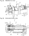
- Figs. 2A and 2B are respectively a perspective view and a cross-sectional view illustrating a schematic configuration of the cord support device 5 having the delay unit 5a in the first embodiment of the present invention.
- Fig. 3 is an exploded perspective view illustrating a schematic configuration of the delay unit 5a in the first embodiment of the present invention.
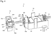
- Fig. 4 is a perspective view illustrating a method of assembling the cord support device 5 having the delay unit 5a in the first embodiment of the present invention.
- the cord support device 5 illustrated in Fig. 2A is configured to align the delay unit 5a to the cord support unit 5b.
- the cord support unit 5b rotatably supports the tilt drum 51 and the winding shaft 52 with the drive shaft 11 as an axis of rotation by the support case 50.
- the ladder cords 9 (refer to Fig. 1 ) to be hung down from the tilt drum 51 and the lift cord 10 (refer to Fig. 1 ) to be hung down from the winding shaft 52 are led from an outlet 50a provided in a bottom surface of the support case 50.
- the tilt drum 51 is relatively nonrotatably coupled with the drive shaft 11 to be supported by the support case 50.
- the winding shaft 52 is not coupled (not engaged) with the drive shaft 11 to be supported by the support case 50.
- the obstacle detecting and stopping device 53 is provided on a tip end side of the winding shaft 52 to prevent rotation of the winding shaft 52 supporting the lift cord 10 when no tension in a pull-out direction is exerted on the lift cord 10, and the obstacle detecting and stopping device 53 is also not coupled (not engaged) with the drive shaft 11 to be supported by the support case 50.
- a case body of the obstacle detecting and stopping device 53 is fixed to the tip end side of the winding shaft 52 while a tubular camshaft 531 stored in the case body of the obstacle detecting and stopping device 53 is rotatable integrally with rotation of the winding shaft 52 with a clearance (i.e., an amount of rotation to prevent rotation of the winding shaft 52) necessary to discontinue, when the bottom rail 8 collides with an obstacle during lowering of the slats 4, unwinding of the lift cord 10 and stop lowering of the slats 4 and the bottom rail 8.
- the delay unit 5a aligned to the support case 50 of the cord support unit 5b is, as illustrated in Fig. 3 , configured with an output shaft member 56, a brake spring 57, a spring case 58, a rotation relay plate 59, an input shaft member 60, and case members 55a and 55b.
- the output shaft member 56 has a tubular stem 561 with a hexagonal outer profile and an approximately cylindrical shaft 562 protruding through a flange 567 with a tubular stem 568 on a base end side (drive transmission input side) of the stem 561, and is provided with a projection 564 projecting to the drive transmission input side within a predetermined angular range (angle ⁇ 1 described later) from the axial center in part of an outer periphery of the cylindrical shaft 562.
- the stem 568 and the flange 567 of the output shaft member 56 are relatively rotatably supported respectively by circular openings 559c and open side faces 559a in one side (drive transmission output side) of the case members 55a and 55b.
- cylindrical shaft 562 and the projection 564 are formed to protrude in a continuous shape in the present example, the cylindrical shaft 562 and the projection 564 may protrude separately.
- the cylindrical shaft 562 has a recessed area in the outer periphery other than the projection 564, the recessed area formed as an engagement bearing 563 to be the range of movement of a projecting piece 592 of the rotation relay plate 59 described later.
- a shaft hole 565 is formed that allows the drive shaft 11 to be inserted without engagement.
- the tubular stem 561 with a hexagonal outer profile allows integrally rotatable engagement with the tubular camshaft 531 having a hexagonal shaft hole 531a of the obstacle detecting and stopping device 53 (refer to Fig. 4 ), and thus rotation of the output shaft member 56 may be transmitted for rotation in synchronization with the camshaft 531 of the obstacle detecting and stopping device 53 (refer to Fig. 2B ).
- the brake spring 57 and the spring case 58 function as brake members to inhibit rotation of the output shaft member 56 other than rotation due to transmission from the input shaft member 60. More specifically, a predetermined braking force is applied to rotation of the output shaft member 56 transmitted from the camshaft 531 of the obstacle detecting and stopping device 53. That is, the brake members including the brake spring 57 and the spring case 58 function as a stopper to lock rotation of the drive shaft 11 so as to prevent the slats 4 and the bottom rail 8 from falling by their own weight.
- the winding shaft 52 should not freely move except during raising and lowering operation by fitting a pair of ends 571 of the brake spring 57 in a coil shape respectively into both sides of the projection 564 of the output shaft member 56 for engagement.
- the spring case 58 stores the coiled brake spring 57 in a state of reduced diameter, and thus the brake spring 57 presses an inner periphery of the spring case 58 all the time to apply a predetermined braking force while allowing relative rotation to the spring case 58.
- part of the spring case 58 is provided with a pair of concave portions 582 nonrotatably locked by convex portions 557 provided in the respective case members 55a and 55b and fitted into storage portions 556 of the respective case members 55a and 55b, thereby nonrotatably fixing the spring case 58.
- the rotation relay plate 59 is configured with a roughly cylindrical member having an outer shape approximately identical to a diameter of the brake spring 57 stored in the spring case 58 in a state of reduced diameter and has a shaft hole 591 formed to have the approximately same diameter as that of the shaft hole 565 of the output shaft member 56.
- the shaft hole 591 accordingly allows the drive shaft 11 to be inserted without engagement.
- the rotation relay plate 59 is configured with the roughly cylindrical member, and to be described in more detail, the rotation relay plate 59 has a tip end surface provided with the projecting piece 592 projecting within a predetermined angular range (angle ⁇ 2 described later) from the axial center in a position near the periphery.
- the rotation relay plate 59 is relatively rotatably stored in the storage portions 556 of the respective case members 55a and 55b while the tip end surface of the rotation relay plate 59 is arranged to allow abutment on a base end surface of the output shaft member 56 through inside the brake spring 57 (refer to Fig. 2B ).
- the projecting piece 592 on the tip end surface of the rotation relay plate 59 is thus relatively rotatable within the range of the engagement bearing 563 in the recessed area other than the projection 564 in the output shaft member 56, that is, even when the rotation relay plate 59 rotates, the rotation is not transmitted to the output shaft member 56 until the projecting piece 592 abuts on the projection 564 in the output shaft member 56 via the ends 571 of the brake spring 57 while, after the abutment, the rotation of the rotation relay plate 59 is transmitted to the output shaft member 56.
- the engagement bearing 593 in a groove shape is formed around the shaft hole 591 partially except a rotation bearing 594.
- the rotation bearing 594 is formed within a predetermined angular range (angle ⁇ 3 described later) from the axial center of the shaft hole 591.
- the engagement bearing 593 in the present example is in a groove shape to form the rotation bearing 594 while it does not have to be in a groove shape as long as it functions similarly.
- the input shaft member 60 has a tubular stem 601 with an approximately quadrangular shaft hole 602 directly coupled with the drive shaft 11 and a projecting piece 603 projecting in alignment with the stem 601 within a predetermined angular range (angle ⁇ 4 described later) from the axial center of the stem 601 formed through a flange 604 with a tubular stem 606.
- a drive transmission output side of the flange 604 of the input shaft member 60 is arranged to allow abutment on a drive transmission input side of the rotation relay plate 59 (refer to Fig.
- the stem 606 and the flange 604 of the input shaft member 60 are relatively rotatably supported respectively by circular openings 559d at an end on a drive transmission input side and storage portions 555 of the case members 55a and 55b.
- the stem 601 is capable of supporting the shaft hole 565 of the output shaft member 56 and the shaft hole 591 of the rotation relay plate 59.
- the projecting piece 603 of the input shaft member 60 is thus relatively rotatable within a range of the engagement bearing 593 of the rotation relay plate 59, that is, even when the input shaft member 60 directly coupled with the drive shaft 11 rotates, the rotation is not transmitted to the rotation relay plate 59 until the projecting piece 603 abuts on the rotation bearing 594 of the rotation relay plate 59 while, after the abutment, rotation of the input shaft member 60 is transmitted to the rotation relay plate 59.
- the delay unit 5a in the first embodiment applies, until the rotation of the input shaft member 60 is transmitted to the output shaft member 56, a total delay of a delay between the input shaft member 60 and the rotation relay plate 59 and a delay between the rotation relay plate 59 and the output shaft member 56.
- the delay between the rotation relay plate 59 and the output shaft member 56 is a delay ⁇ between the projection 564 projecting within the range of the angle ⁇ 1 and the projecting piece 592 projecting within the range of the angle ⁇ 2.
- the delay between the input shaft member 60 and the rotation relay plate 59 is a delay ⁇ between the rotation bearing 594 within the range of the angle ⁇ 3 and the projecting piece 603 projecting within the range of the angle ⁇ 4.
- the delay ⁇ ⁇ 240 degrees is a delay ⁇ between the projection 564 projecting within the range of the angle ⁇ 1 and the projecting piece 592 projecting within the range of the angle ⁇ 2.
- the delay until the rotation of the input shaft member 60 is transmitted to the output shaft member 56 is then ⁇ + ⁇ ⁇ 450 degrees. Accordingly, setting of the amount of rotation delayed by the delay unit 5a as an angular adjustment range of the slats 4 or more allows achievement of various delays and the rotation relay plate 59 functions as a delay adjustment member to relay rotation with a predetermined delay.
- a member to rotate in direct coupling with the drive shaft 11 is only the input shaft member 60. Only by aligning the delay unit 5a in the first embodiment on the drive shaft 11, corotation is achieved with a predetermined delay relatively from the rotation of the tilt drum 51 relative to rotation of the winding shaft 52 via the obstacle detecting and stopping device 53 (refer to Figs. 4 and 2B ).
- the case members 55a and 55b of the delay unit 5a in the first embodiment have nails 558 to hold a projection 50b provided in the support case 50 of the cord support unit 5b respectively formed on side walls on the drive transmission output side.
- This allows stable assembly of the delay unit 5a in the first embodiment to the cord support unit 5b on the drive shaft 11 in a simple and detachable manner.
- the stem 561 of the output shaft member 56 in the delay unit 5a is engaged with the shaft hole 531a of the camshaft 531 in the obstacle detecting and stopping device 53 for integrally rotatable coupling.
- the support case 50 is preferably provided with an inhibition wall 50j to inhibit upward movement of the camshaft 531.
- the rotation relay plate 59 may be omitted to directly connect the input shaft member 60 to the output shaft member 56, allowing a configuration of applying a delay between the input shaft member 60 and the output shaft member 56 to produce different delays commonly using the same output shaft member 56, brake spring 57, spring case 58, and input shaft member 60.
- the delay between the input shaft member 60 and the output shaft member 56 using no rotation relay plate 59 is a delay ⁇ between the projection 564 projecting within the range of the angle ⁇ 1 and the projecting piece 603 projecting within the range of the angle ⁇ 4.
- the delay ⁇ ⁇ 240 degrees Accordingly, setting of the amount of rotation delayed by the delay unit 5a as the angular adjustment range of the slats 4 or more allows achievement of various delays.
- the case members 55a and 55b are designed to store the output shaft member 56, the brake spring 57, the spring case 58, the rotation relay plate 59, and the input shaft member 60 by fitting formation in a vertical direction (in the present example, a fore and aft direction) to the drive shaft 11. More specifically, the case member 55a has an upper surface and a lower surface respectively formed to have fitting receptions 551 with projections 553, and the case member 55b has an upper surface and a lower surface respectively formed to have fitting pieces 552 with holes 554 allowing fitting with the projections 553 to be engaged with the fitting receptions 551.
- fitting formation in a parallel direction to the drive shaft 11 may cause a problem in quality due to reduction in the fitting force by the rotation of the drive shaft 11 and thus requires combination formation using screws and the like, whereas a configuration of fitting formation in a vertical direction to the drive shaft 11 as in the present embodiment does not require combination formation with screws and the like due to the strong fitting force against rotation of the drive shaft 11 and thus inclusively contributes to facilitation of assembly and inexpensiveness.
- the present embodiment has described the example of engaging the stem 561 of the output shaft member 56 with the camshaft 531 of the obstacle detecting and stopping device 53 in a hexagonal shape while, from the perspective of improvement in assemblability, an engagement shape preferably has more sides. That is, the stem 561 of the output shaft member 56 is configured to have a polygonal shape and the camshaft 531 of the obstacle detecting and stopping device 53 is configured to be engaged with the stem 561, thereby allowing assembly by slight rotary operation and improvement in assemblability.
- the bottom rail 8 is not raised and lowered due to the tilting operation even in the configuration allowing operation of rotation of the tilt drum 51 and the winding shaft 52 with the one drive shaft 11.
- impairment of the operability does not occur such as raising of the stacked slats 4 before tilted during tilting operation.
- the bottom rail 8 is not raised and lowered as illustrated in Fig. 6B even by adjusting the angle of the slats 4 by tilting operation.
- impairment of the operability does not occur such as raising of the stacked slats 4 before tilted during tilting operation.
- the case members 55a and 55b have upper corner portions 550a formed with a rectangular recess. Accordingly, when the delay unit 5a is mounted in the head box 1, the upper corner portions 550a of the delay unit 5a supported by lower corner portions 550b are engaged with an upper end of the head box 1 (refer to Figs. 6A, 6B, and 6C ) to suppress a wobble in the fore and aft direction and the up and down direction. Since the nails 558 are formed in the case members 55a and 55b of the delay unit 5a, the holding to the projection 50b of the support case 50 in the cord support unit 5b also inhibits a wobble in the left and right directions.
- the present embodiment has described the example of engaging the stem 561 of the output shaft member 56 with the camshaft 531 of the obstacle detecting and stopping device 53 while the actions and effects according to the present invention may be exhibited even when the output shaft member 56 is engaged with the winding shaft 52 not via the obstacle detecting and stopping device 53.
- FIGs. 7A and 7B are respectively a perspective view and a cross-sectional view illustrating a schematic configuration of a cord support device 5 having the delay unit 5a in the second embodiment of the present invention.
- Fig. 8 is an exploded perspective view illustrating a schematic configuration of the delay unit 5a in the second embodiment of the present invention.
- Fig. 9 is a perspective view illustrating a method of assembling the cord support device 5 having the delay unit 5a in the second embodiment of the present invention.
- identical reference signs are given to components having the same function in the first embodiment.
- the cord support device 5 having the delay unit 5a in the second embodiment illustrated in Fig. 7A is configured to align the delay unit 5a to the cord support unit 5b in the same manner as the first embodiment.
- the cord support unit 5b related to the delay unit 5a in the second embodiment rotatably supports, in the same manner as the first embodiment, the tilt drum 51 and the winding shaft 52 with the drive shaft 11 as an axis of rotation by the support case 50.
- the ladder cords 9 to be hung down from a tilt drum 51 and a lift cord 10 to be hung down from the winding shaft 52 are led from the outlet 50a provided in the bottom surface of the support case 50.
- the winding shaft 52 of the cord support unit 5b related to the delay unit 5a in the second embodiment is capable of winding or unwinding a tape-like lift cord 10 in multiple layers and a tilt drum 51 is attached to a hanging member 511 of a torsion coil spring to hangingly support the ladder cords 9.
- a configuration of the cord support unit 5b is suitable for Venetian blinds required to be miniaturized.
- the hanging member 511 has looped ladder cord attachment portions 511a and locking ends 511b formed by bending both ends of the torsion coil spring.
- the pair of front and rear ladder cords 9 have upper ends attached to the ladder cord attachment portions 511a for hanging support.
- the hanging member 511 is attached by clamping the tilt drum 51 and integrally rotates with the tilt drum 51 until either of the locking ends 511b abut on a wall formed in the support case 50 while abutment of the locking end 511b on the wall formed in the support case 50 weakens the clamping force and the hanging member 511 idles relative to the tilt drum 51. Based on rotation of the tilt drum 51, each slat 4 is thus angularly adjusted in the same phase via the ladder cords 9.
- the delay unit 5a in the first embodiment illustrated in Fig. 3 may be applied to the cord support unit 5b in the second embodiment, the delay unit 5a in the second embodiment is configured as illustrated in Fig. 8 for the purpose of miniaturization.
- the delay unit 5a in the second embodiment has a configuration, compared with the first embodiment, where the rotation relay plate 59 is omitted and the case members 55a and 55b have a smaller shape and has others in common with the first embodiment, such as the output shaft member 56, the brake spring 57, the spring case 58, and the input shaft member 60.
- the shape of the case members 55a and 55b has the same action and effects as the first embodiment other than the contribution to miniaturization by, compared with the first embodiment, omitting formation of the storage portions 555 to store the rotation relay plate 59 and relatively rotatably supporting the stem 606 and the flange 604 of the input shaft member 60 respectively by the circular openings 559d at an end on the drive transmission input side and open side faces 559b of the case members 55a and 55b.
- the delay unit 5a in the second embodiment has a configuration to omit the rotation relay plate 59 and directly connect the input shaft member 60 to the output shaft member 56 for application of the delay between the input shaft member 60 and the output shaft member 5.
- Such a configuration produces different delays while using the same output shaft member 56, brake spring 57, spring case 58, and input shaft member 60 in common with the first embodiment.
- the delay between the input shaft member 60 and the output shaft member 56 using no rotation relay plate 59 is the delay ⁇ between the projection 564 projecting within the range of the angle ⁇ 1 and the projecting piece 603 projecting within the range of the angle ⁇ 4.
- the delay ⁇ ⁇ 240 degrees Accordingly, setting of the amount of rotation delayed by the delay unit 5a as the angular adjustment range of the slats 4 or more allows achievement of various delays.
- the tilt drum 51 is relatively nonrotatably coupled with the drive shaft 11 to be supported by the support case 50.
- the winding shaft 52 is not coupled (not engaged) with the drive shaft 11 to be supported by the support case 50.
- the obstacle detecting and stopping device 53 is provided on a tip end side of the winding shaft 52 to prevent rotation of the winding shaft 52 supporting the lift cord 10 when no tension in a pull-out direction is exerted on the lift cord 10, and the obstacle detecting and stopping device 53 is also not coupled (not engaged) with the drive shaft 11 to be supported by the support case 50.
- a case body of the obstacle detecting and stopping device 53 is fixed to the tip end side of the winding shaft 52 while a tubular camshaft 531 stored in the case body of the obstacle detecting and stopping device 53 is rotatable integrally with rotation of the winding shaft 52 with a clearance necessary to discontinue, when the bottom rail 8 collides with an obstacle during lowering of the slats 4, unwinding of the lift cord 10 and stop lowering of the slats 4 and the bottom rail 8 and also to prevent reverse winding of the lift cord 10.
- a member to rotate in direct coupling with the drive shaft 11 is only the input shaft member 60. Only by aligning the delay unit 5a in the second embodiment on the drive shaft 11, corotation is achieved with a predetermined delay relatively from the rotation of the tilt drum 51 relative to rotation of the winding shaft 52 via the obstacle detecting and stopping device 53 (refer to Figs. 9 and 7B ).
- the case members 55a and 55b of the delay unit 5a in the second embodiment have nails 558 to hold a projection 50b provided in the support case 50 of the cord support unit 5b respectively formed on side walls on the drive transmission output side. This allows stable assembly of the delay unit 5a in the second embodiment to the cord support unit 5b on the drive shaft 11 in a simple and detachable manner.
- case members 55a and 55b are configured to form fitting in a vertical direction to the drive shaft 11, and due to the strong fitting force against rotation of the drive shaft 11, do not require combination formation with screws and the like and thus inclusively contribute to facilitation of assembly and inexpensiveness.
- the case members 55a and 55b have the upper corner portions 550a formed with a rectangular recess. Accordingly, when the delay unit 5a is mounted in the head box 1, the respective upper corner portions 550a of the delay unit 5a supported by the lower corner portions 550b are engaged with the upper end of the head box 1 (similar to Figs. 6A, 6B, and 6C above) to suppress a wobble in the fore and aft direction and the up and down direction. Since the nails 558 are formed in the case members 55a and 55b of the delay unit 5a, the holding to the projection 50b of the support case 50 in the cord support unit 5b also inhibits a wobble in the left and right directions.
- the stem 561 of the output shaft member 56 is configured to have a polygonal shape and the camshaft 531 of the obstacle detecting and stopping device 53 is configured to be engaged with the stem 561, thereby allowing assembly by slight rotary operation and improvement in assemblability.
- the bottom rail 8 is not raised and lowered due to the tilting operation even in the configuration allowing operation of rotation of the tilt drum 51 and the winding shaft 52 with the one drive shaft 11.
- impairment of the operability does not occur such as raising of the stacked slats 4 before tilted during tilting operation.
- the present embodiment has described the example of engaging the stem 561 of the output shaft member 56 with the camshaft 531 of the obstacle detecting and stopping device 53 while the action and effects according to the present invention may be exhibited even when the output shaft member 56 is engaged with the winding shaft 52 not via the obstacle detecting and stopping device 53.
- the delay units 5a in the first and second embodiments may be applied, while keeping the shape and the structure, to a cord support unit 5b configured to wind a string-like lift cord 10 by helical shaft 52C for helical winding to configure a cord support device 5.
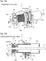
- Figs. 10A and 10B are respectively a perspective view and a cross-sectional view illustrating a schematic configuration of the cord support device 5 for helical winding having the delay unit 5a in the second embodiment of the present invention.
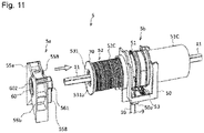
- Fig. 11 is a perspective view illustrating a method of assembling the cord support device 5 for helical winding having the delay unit 5a in the second embodiment of the present invention.
- identical reference signs are given to components having the same function in the first embodiment.
- the cord support device 5 for helical winding illustrated in Fig. 10A is configured, similar to the above description, to align the delay unit 5a to the cord support unit 5b.
- the helical shaft 52C in the cord support unit 5b illustrated in Fig. 10A has an approximately cylindrical body into which the drive shaft 11 is inserted without engagement (without coupling) and has helical screwing projecting threads formed in a surface thereof and that an upper end of the lift cord 10 is attached to the recess near a tip end of the helical shaft 52C, allowing winding or unwinding of the lift cord 10.
- the helical screwing projecting threads in the helical shaft 52C allow screwing to helical screwed projecting threads 50d in an inner periphery provided in the support case 50, and with rotation of the helical shaft 52C (winding shaft 52), the helical shaft 52C itself relatively moves to a casing 51C thereof in the axial direction.
- the casing 51C is attached to the hanging member 511 of a torsion coil spring to form a tilt drum 51 hangingly supporting the ladder cords 9.
- the hanging member 511 has the looped ladder cord attachment portions 511a and the locking ends 511b formed by bending both ends of the torsion coil spring and is attached by clamping the tilt drum 51.
- the hanging member 511 integrally rotates with the tilt drum 51 until either of the locking ends 511b abut on the wall formed in the support case 50 while abutment of the locking end 511b on the wall formed in the support case 50 weakens the clamping force and the hanging member 511 idles relative to the tilt drum 51. Based on rotation of the tilt drum 51, each slat 4 is thus angularly adjusted in the same phase via the ladder cords 9.
- the support case 50 rotatably supports the tilt drum 51 and the winding shaft 52 with the drive shaft 11 as an axis of rotation.
- the ladder cords 9 to be hung down from a tilt drum 51 and the lift cord 10 to be hung down from the winding shaft 52 are led from the outlet 50a provided in the bottom surface of the support case 50.
- the casing 51C tilt drum 51
- the winding shaft 52 is not coupled with the drive shaft 11 to be supported by the support case 50.
- the delay unit 5a in the second embodiment is configured to be attached via a disk-shaped support auxiliary member 70 firmly fixed to the tip end of the helical shaft 52C (winding shaft 52).
- a member to rotate in direct coupling with the drive shaft 11 is only the input shaft member 60. Only by aligning the delay unit 5a in the second embodiment on the drive shaft 11, corotation is achieved with a predetermined delay relatively from the rotation of the tilt drum 51 relative to rotation of the helical shaft 52C (winding shaft 52) (refer to Figs. 11 and 10B ).
- the case members 55a and 55b of the delay unit 5a in the second embodiment have the nails 558 to hold the disk-shaped support auxiliary member 70 provided in the helical shaft 52C (winding shaft 52) of the cord support unit 5b.
- This allows stable assembly of the delay unit 5a in the second embodiment to the helical cord support unit 5b on the drive shaft 11 in a simple and detachable manner.
- the delay units 5a in the first and second embodiments above have described in that such a delay unit 5a is aligned outside the various forms of support case 50 to improve assemblability in the configuration of the cord support device 5 and is excellent in practicality contributing to miniaturization, versatility reduction of operations and expenses for parts control, and inexpensiveness of the cord support device 5.
- members used in common are intended to be increased as much as possible regarding contribution to reduction of operations and expenses for parts control and inexpensiveness as important.
- the delay units 5a in the first and second embodiments avoid such increase in size to produce the effective action and effects.
- the delay unit 5a in the first embodiment illustrated in Fig. 3 has a configuration with the greater case members 55a and 55b in the left and right directions compared with the delay unit 5a in the second embodiment.
- the delay unit 5a in the first embodiment illustrated in Fig. 3 has a configuration with the greater case members 55a and 55b in the left and right directions compared with the delay unit 5a in the second embodiment.
- a request is assumed for a smaller width in the left and right directions of the case members 55a and 55b of the delay unit 5a in the first embodiment.
- third and fourth embodiments are described in order as configuration examples regarding miniaturization of the delay unit 5a itself in the left and right directions as more important than contribution to reduction of operations and expenses for parts control and inexpensiveness.
- the first and second embodiments are configured to link the rotation transmission sections to produce a predetermined delay in the axial direction of the drive shaft 11 while third and fourth embodiments are configured to link rotation transmission sections to produce the predetermined delay in the vertical direction to the drive shaft 11 to have a smaller width of the case members 55a and 55b in the left and right directions of the delay unit 5a in third and fourth embodiments.
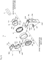
- Fig. 12 is an exploded perspective view illustrating a schematic configuration of a delay unit in the third embodiment of the present invention. Identical reference signs are given to components having the same function in the first embodiment described above.
- a delay unit 5a in the present embodiment is configured with, in the same manner as the first embodiment described above, an output shaft member 56, a brake spring 57, a spring case 58, a rotation relay plate 59, an input shaft member 60, and case members 55a and 55b.
- the output shaft member 56 in the present embodiment is provided with a tubular stem 561 having an octagonal outer profile and a projection 564 projecting to a drive transmission input side within a predetermined angular range (angle ⁇ 1 described later) from the axial center near part of the outer periphery through a flange 567 with a tubular stem 568 on a base end side (drive transmission input side) of the stem 561.
- the stem 568 and the flange 567 of the output shaft member 56 are relatively rotatably supported respectively by circular openings 559c in open side faces 559a on one side (drive transmission output side) and the open side faces 559a of the case members 55a and 55b.
- the output shaft member 56 in the present embodiment has engagement bearings 563a and 563b, recessed stepwise, formed in a surface on a base end side (drive transmission input side) of the flange 567.
- a shaft hole 565 is formed that allows the drive shaft 11 to be inserted without engagement.
- the tubular stem 561 with an octagonal outer profile allows integrally rotatable engagement with the tubular camshaft 531 having an octagonal shaft hole 531a of the obstacle detecting and stopping device 53, and thus rotation of the output shaft member 56 may be transmitted for rotation in synchronization with the camshaft 531 of the obstacle detecting and stopping device 53 (similar to Fig. 2B above).
- the brake spring 57 and the spring case 58 have greater diameters than those in the first and second embodiments to store a rotation relay plate 59 in the present embodiment described later inside them, and similar to the first and second embodiments described above, function as brake members to inhibit rotation of the output shaft member 56 other than rotation due to transmission from the input shaft member 60. That is, a predetermined braking force is applied to rotation of the output shaft member 56 transmitted from the camshaft 531 of the obstacle detecting and stopping device 53.
- the winding shaft 52 should not freely move except during raising and lowering operation by fitting a pair of ends 571 of the brake spring 57 in a coil shape respectively into both sides of the projection 564 of the output shaft member 56 for engagement.
- the spring case 58 stores the coiled brake spring 57 in a state of reduced diameter, and thus the brake spring 57 presses an inner periphery of the spring case 58 all the time to apply a predetermined braking force while allowing relative rotation to the spring case 58. Meanwhile, part of the spring case 58 is provided with a pair of concave portions 582 nonrotatably locked by convex portions 557 provided in the respective case members 55a and 55b and fitted into storage portions 556 of the respective case members 55a and 55b, thereby nonrotatably fixing the spring case 58.
- the rotation relay plate 59 in the present embodiment is markedly different from that in the first embodiment described above.
- the rotation relay plate 59 in the present embodiment is configured with a roughly cylindrical member with an outer shape smaller than a diameter of the brake spring 57 stored in the spring case 58 in a state of reduced diameter having a projection 592a in part of the outer periphery and a rotation bearing 594 in part of the inner periphery, and has a shaft hole 591 formed to have the approximately same diameter as that of the shaft hole 565 of the output shaft member 56.
- the shaft hole 591 accordingly allows the drive shaft 11 to be inserted without engagement.
- the drive transmission output side of the rotation relay plate 59 has a shape allowing abutment on engagement bearings 563a and 563b in a drive transmission input side of the output shaft member 56 through inside the brake spring 57, and in the state of abutting arrangement, the rotation relay plate 59 is located inside the brake spring 57 stored in the spring case 58 in a state of reduced diameter to be relatively rotatably stored in the respective case members 55a and 55b.
- the projection 592a of the rotation relay plate 59 is thus relatively rotatable within the range of the engagement bearing 563b in the recessed area other than the projection 564 in the output shaft member 56, that is, even when the rotation relay plate 59 rotates, the rotation is not transmitted to the output shaft member 56 until the projection 592a abuts on the projection 564 in the output shaft member 56 via the ends 571 of the brake spring 57 while, after the abutment, the rotation of the rotation relay plate 59 is transmitted to the output shaft member 56.
- the engagement bearing 593 in a recessed shape is formed around the shaft hole 591 partially except a rotation bearing 594.
- the rotation bearing 594 is formed within a predetermined angular range (angle ⁇ 3 described later) from the axial center of the shaft hole 591.
- angle ⁇ 3 described later
- the example of forming the rotation bearing 594 and the projection 592a within the same range of rotational angles is described in the present example while the rotation bearing 594 and the projection 592a may be changed in size and arrangement depending on the application.
- the input shaft member 60 has a tubular stem 601 with an approximately quadrangular shaft hole 602 directly coupled with the drive shaft 11 and a projecting piece 603 projecting in alignment with the stem 601 within a predetermined angular range (angle ⁇ 4 described later) from the axial center of the stem 601 formed in a drive transmission output side of a flange 604 with a tubular stem 606.
- the stem 606 and the flange 604 of the input shaft member 60 are relatively rotatably supported respectively by circular openings 559d at an end on a drive transmission input side of the storage portions 556 and open side faces 559b of the case members 55a and 55b.
- the stem 601 is capable of supporting the shaft hole 565 of the output shaft member 56 and the shaft hole 591 of the rotation relay plate 59.
- the projecting piece 603 of the input shaft member 60 is thus relatively rotatable within a range of the engagement bearing 593 of the rotation relay plate 59, that is, even when the input shaft member 60 directly coupled with the drive shaft 11 rotates, the rotation is not transmitted to the rotation relay plate 59 until the projecting piece 603 abuts on the rotation bearing 594 of the rotation relay plate 59 while, after the abutment, rotation of the input shaft member 60 is transmitted to the rotation relay plate 59.
- the delay unit 5a in the third embodiment applies, until the rotation of the input shaft member 60 is transmitted to the output shaft member 56, a total delay of a delay between the input shaft member 60 and the rotation relay plate 59 and a delay between the rotation relay plate 59 and the output shaft member 56.
- the delay between the rotation relay plate 59 and the output shaft member 56 is a delay ⁇ between the projection 564 projecting within the range of the angle ⁇ 1 and the projection 592a projecting within the range of the angle ⁇ 2.
- the delay between the input shaft member 60 and the rotation relay plate 59 is a delay ⁇ between the rotation bearing 594 within the range of the angle ⁇ 3 and the projecting piece 603 projecting within the range of the angle ⁇ 4.
- the delay until the rotation of the input shaft member 60 is transmitted to the output shaft member 56 is then ⁇ + ⁇ .
- the delay unit 5a in the present embodiment is capable of achieving equivalent functions as those of the delay unit 5a in the first embodiment and the rotation relay plate 59 functions as a delay adjustment member to relay rotation with a predetermined delay.
- the delay unit 5a in the present embodiment is configured to have the rotation relay plate 59 located inside the spring case 58 to be stored in the case members 55a and 55b, and is thus capable of achieving an equivalent width in the fore and aft direction and an upper limit direction to that of the delay unit 5a in the first embodiment and also reducing the width in the left and right directions more than that of the delay unit 5a in the first embodiment.
- a member to rotate in direct coupling with the drive shaft 11 is only the input shaft member 60. Only by aligning the delay unit 5a in the third embodiment on the drive shaft 11, corotation is achieved with a predetermined delay relatively from the rotation of the tilt drum 51 relative to rotation of the winding shaft 52 via the obstacle detecting and stopping device 53 (similar to Figs. 4 and 2B above).
- the case members 55a and 55b of the delay unit 5a in the first embodiment have nails 558 to hold a projection 50b provided in the support case 50 of the cord support unit 5b respectively formed on side walls on the drive transmission output side. This allows stable assembly of the delay unit 5a in the third embodiment to the cord support unit 5b on the drive shaft 11 in a simple and detachable manner.
- the bottom rail 8 is not raised and lowered due to the tilting operation.
- impairment of the operability does not occur such as raising of the stacked slats 4 before tilted during tilting operation (similar to Figs. 6A, 6B, and 6C above).
- the case members 55a and 55b have the upper corner portions 550a formed with a rectangular recess. Accordingly, when the delay unit 5a is mounted in the head box 1, the respective upper corner portions 550a of the delay unit 5a supported by the lower corner portions 550b are engaged with the upper end of the head box 1 (similar to Figs. 6A, 6B, and 6C above) to suppress a wobble in the fore and aft direction and the up and down direction. Since the nails 558 are formed in the case members 55a and 55b of the delay unit 5a, the holding to the projection 50b of the support case 50 in the cord support unit 5b also inhibits a wobble in the left and right directions.
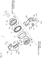
- Fig. 13 is an exploded perspective view illustrating a schematic configuration of the delay unit in the fourth embodiment of the present invention. Identical reference signs are given to components having the same function in the third embodiment described above. As illustrated in Fig. 13 , similar to the third embodiment described above, the delay unit 5a in the present embodiment is configured with the output shaft member 56, the brake spring 57, the spring case 58, an input shaft member 60, and case members 55a and 55b.
- the delay unit 5a in the fourth embodiment has a configuration, compared with the third embodiment, where the case members 55a and 55b are kept in the shape while miniaturized, the rotation relay plate 59 is omitted, and the shape of the input shaft member 60 is changed in association with the above changes and has others in common with the third embodiment, such as the output shaft member 56, the brake spring 57, and the spring case 58.
- the input shaft member 60 of the delay unit 5a in the fourth embodiment has a tubular stem 601 with an approximately quadrangular shaft hole 602 directly coupled with the drive shaft 11, a tubular relay stem 605 continued in a base end side of the stem 601, having a greater diameter, and having a quadrangular shaft hole 602, and a projecting piece 603a projecting in alignment with the relay stem 605within a predetermined angular range (angle ⁇ 5 described later) from the axial center of the stem 601 and the relay stem 605 formed through a flange 604.
- the stem 601 is capable of supporting the shaft hole 565 of the output shaft member 56.
- an interface with the stem 601 in the relay stem 605 is arranged to allow abutment on the engagement bearing 563a in the base end surface of the output shaft member 56 through inside the brake spring 57, the stem 606 and the flange 604 of the input shaft member 60 are relatively rotatably supported respectively by circular openings 559d at ends on a drive transmission input side of storage portions 556 and open side faces 559b of the case members 55a and 55b.
- the relay stem 605 is located inside the brake spring 57 stored in the spring case 58 in a state of reduced diameter to be relatively rotatably stored in the respective case members 55a and 55b.
- the projecting piece 603a of the input shaft member 60 is thus relatively rotatable within a range of the engagement bearing 563b in the base end surface of the output shaft member 56, that is, even when the input shaft member 60 directly coupled with the drive shaft 11 rotates, the rotation is not transmitted to the output shaft member 56 until the projecting piece 603a abuts on the projection 564 of the output shaft member 56 while, after the abutment, rotation of the input shaft member 60 is transmitted to the output shaft member 56.
- the case members 55a and 55b also have a shape keeping more contribution to miniaturization and have the same action and effects as those in the third embodiment.
- the delay between the input shaft member 60 and the output shaft member 56 using no rotation relay plate 59 is the delay ⁇ between the projection 564 projecting within the range of the angle ⁇ 1 and the projecting piece 603a projecting within the range of the angle ⁇ 5.
- the tilt drum 51 is relatively nonrotatably coupled with the drive shaft 11 to be supported by the support case 50.
- the winding shaft 52 is not coupled (not engaged) with the drive shaft 11 to be supported by the support case 50.
- the obstacle detecting and stopping device 53 is provided on a tip end side of the winding shaft 52 to prevent rotation of the winding shaft 52 supporting the lift cord 10 when no tension in a pull-out direction is exerted on the lift cord 10, and the obstacle detecting and stopping device 53 is also not coupled (not engaged) with the drive shaft 11 to be supported by the support case 50.
- a case body of the obstacle detecting and stopping device 53 is fixed to the tip end side of the winding shaft 52 while a tubular camshaft 531 stored in the case body of the obstacle detecting and stopping device 53 is rotatable integrally with rotation of the winding shaft 52 with a clearance necessary to discontinue, when the bottom rail 8 collides with an obstacle during lowering of the slats 4, unwinding of the lift cord 10 and stop lowering of the slats 4 and the bottom rail 8 and also to prevent reverse winding of the lift cord 10.
- a member to rotate in direct coupling with the drive shaft 11 is only the input shaft member 60. Only by aligning the delay unit 5a in the fourth embodiment on the drive shaft 11, corotation is achieved with a predetermined delay relatively from the rotation of the tilt drum 51 relative to rotation of the winding shaft 52 via the obstacle detecting and stopping device 53 (similar to Fig. 9 above).
- the case members 55a and 55b have nails 558 to hold a projection 50b provided in the support case 50 of the cord support unit 5b respectively formed on side walls on the drive transmission output side. This allows stable assembly of the delay unit 5a in the fourth embodiment to the cord support unit 5b on the drive shaft 11 in a simple and detachable manner.
- the delay units 5a in the third and fourth embodiments may be applied, similar to those in the first and second embodiments, to a cord support unit 5b configured to wind a string-like lift cord 10 by helical shaft 52C for helical winding to configure a cord support device 5 (refer to Figs. 10A and 10B above).
- the case members 55a and 55b of the delay unit 5a in the fourth embodiment have the nails 558 to hold the disk-shaped support auxiliary member 70 provided in the helical shaft 52C (winding shaft 52) of the cord support unit 5b. This allows stable assembly of the delay unit 5a in the fourth embodiment to the helical cord support unit 5b on the drive shaft 11 in a simple and detachable manner.
- the case members 55a and 55b have the upper corner portions 550a formed with a rectangular recess. Accordingly, when the delay unit 5a is mounted in the head box 1, the respective upper corner portions 550a of the delay unit 5a supported by the lower corner portions 550b are engaged with the upper end of the head box 1 (similar to Figs. 6A, 6B, and 6C above) to suppress a wobble in the fore and aft direction and the up and down direction. Since the nails 558 are formed in the case members 55a and 55b of the delay unit 5a, the holding to the projection 50b of the support case 50 in the cord support unit 5b also inhibits a wobble in the left and right directions.
- Fig. 15 is a top view illustrating a configuration for assembly inside a head box 1 related to a delay unit 5a in one embodiment of the present invention.
- Fig. 15 illustrates a configuration for assembly inside the head box 1 using the delay unit 5a illustrated in Fig. 13 as an example representative of the delay units 5a in the first to fourth embodiments described above while it should be noted that same applies in any of the first to fourth embodiments above.
- the head box 1 has an upper surface opened with a length L1 in a fore and aft direction and an inside having a storage space roughly with a length L2 (> L1) in the fore and aft direction.
- a cord support unit 5b including a tilt drum 51, a winding shaft 52, and an obstacle detecting and stopping device 53 is stored in a support case 50 to be mounted in the head box 1, controlled by the storage space with the length L2 not to shift in the fore and aft direction and in an up and down direction.
- the cord support unit 5b stored in the support case 50 is thus mounted in the head box 1 by enlarging the upper surface of the head box 1 or being inserted from openings, not shown, at both ends of the head box 1 in left and right directions.
- the delay unit 5a has a length d between sides on a drive transmission input side of case members 55a and 55b and a side on a drive transmission output side of a stem 561 shorter than the length L1 of the opening in the upper surface of the head box 1.
- the delay unit 5a is thus readily mounted in a desired position of the storage space in the head box 1. That is, mounting of the delay unit 5a in the head box 1 does not require enlargement of the upper surface of the head box 1 or insertion from the openings, not shown, at both ends of the head box 1 in the left and right directions.
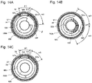
- the delay unit 5a has an outer shape fitting within a circular arc S with a diameter D ( ⁇ L2) from the center of gravity OP.
- the delay unit 5a mounted in the head box 1 may thus face the cord support unit 5b stored in the support case 50 subjected to coupling by, for example, rotation about the center of gravity OP.
- the delay unit 5a is firstly mounted in the storage space of the head box 1 near the cord support unit 5b stored in the support case 50 subjected to coupling. As illustrated in Fig. 16B , the delay unit 5a is then rotated in the storage space of the head box 1 to face the cord support unit 5b stored in the support case 50 subjected to coupling.
- a plurality of such delay units 5a and a plurality of such cord support units 5b are arranged in the head box 1 in accordance with specifications of the intended Venetian blind.
- the plurality of cord support units 5b are arranged in respective orientations in accordance with a position of hanging down the lift cord 10, and the delay units 5a are also arranged in orientations according to the orientations of the respective cord support units 5b subjected to coupling.
- a ladder cord support member 6 may be arranged in an appropriate position.
- a drive shaft 11 is then inserted arbitrarily from the openings, not shown, at both ends of the head box 1 in the left and right directions into the delay units 5a, the cord support units 5b, and the ladder cord support member 6 arranged in the head box 1.
- Functional members such as an operation unit 2, are then arranged and both ends of the head box 1 in the left and right directions are closed with side caps 1c.
- the drive shaft 11 has to be inserted into the plurality of cord support units 5b while positioning of the lift cord 10 is simultaneously performed in all the winding shafts 52 (initially wounded amount and attachment position of each winding shaft 52).
- the delay units 5a described above in the first to fourth embodiments according to the present invention are separated to allow free combination to the plurality of cord support units 5b, and thus the drive shaft 11 may be arbitrarily inserted, allowing reduction in costs (operations and expenses) for the assembly.
- the attachment position (initially wounded amount and attachment position of each winding shaft 52) of the lift cord 10 may be positioned in all the winding shafts 52.
- the drive shaft 11 is arbitrarily rotated several times (approximately, twice) using an operation cord 3 to initialize each delay unit 5a for mounting of the delay units 5a.
- the drive shaft 11 is arbitrarily rotated several times (approximately, twice) using the operation cord 3 for initialization to align the positions of each projection and each projecting piece (e.g., in the example illustrated in Fig. 12 , the projecting piece 603 of the input shaft member 60, the projections 592a and 594 of the rotation relay plate 59, and the projection 564 of the output shaft member 56) inside each delay unit 5a.
- attachment positions (S in Fig. 17D ) of the lift cord 10 on the winding shafts 52 idlable to the drive shaft 11 are then aligned in the respective cord support units 5b, followed by coupling of the respective delay units 5a faced with the respective cord support units 5b subjected to coupling by sliding operation in the left and right directions.
- the respective delay units 5a in the first to fourth embodiments described above have upper corner portions 550a formed with a rectangular recess in the case members 55a and 55b having lower corner portions 550b, and thus the upper corner portions 550a are engaged with the upper end of the head box 1 to allow sliding while suppressing a wobble in the fore and aft direction and the up and down direction. It is thus possible to readily align the positions of the winding shafts 52 in the respective cord support units 5b by initializing the respective delay units 5a and to achieve raising and lowering behavior of the slats 4 balanced in the left and right directions.
- Each delay units 5a has the case members 55a and 55b provided with nails 558, which hold a projection 50b of the support case 50 in each cord support unit 5b to inhibit a wobble in the left and right directions.
- the nails 558 of the delay unit 5a are formed in a position allowing visual recognition of the holding state from the opening in the upper surface of the head box 1 (a position within the range of the length L1 illustrated in Fig. 16B ) with respect to the projection 50b of the cord support unit 5b subjected to coupling, leading to easy coupling.
- the delay unit 5a is capable of reduction in assembly costs (operations and expenses) from this perspective.
- the respective delay units 5a in the first to fourth embodiments are, as illustrated in Fig. 18A , described as examples where the nails 558 described above holds the projection 50b of the support case 50 by fitting to couple the stem 561 (in the illustrated example, an octagonal shaft) of the output shaft member 56 in the delay unit 5a with the shaft hole 531a (in the illustrated example, an octagonal shaft hole) of the camshaft 531 in the obstacle detecting and stopping device 53.
- such shaft coupling may be achieved by a configuration of direct holding (fitting) between the stem 561 and the camshaft 531.
- the stem 561 of the output shaft member 56 is provided in a cylindrical shape and has an inner periphery 561a with convex portions 561b at two facing spots.
- the inner periphery 561a of the stem 561 is also provided with elastically deformable engagement pieces 561d not to interfere with insertion of the drive shaft 11 at two spots orthogonal to the convex portions 561b at the two facing spots.
- Each engagement piece 561d is provided with a fitting projection 561c on an outer surface relative to the axial center of the inner periphery 561a.
- a coupling section in the camshaft 531 of the obstacle detecting and stopping device 53 is, instead of the shaft hole 531a illustrated in Fig. 18A , in a two-level outer peripheral shape having steps of a section 5310 and a section 5319 on the outer periphery, the section 5319 provided with concave portions 531b at two facing spots.
- a fitting wall 531c is provided that has a smaller diameter than that of an inner peripheral wall constituting a shaft hole 5313 of the camshaft 531 and allows insertion of the drive shaft 11.
- the convex portions 561b at two facing spots in the stem 561 are then capable of engaging with the concave portions 531b at two facing spots in the section 5319 of the camshaft 531, and in the coupling state by such engagement, the fitting projections 561c of the elastically deformable engagement pieces 561d of the stem 561 fit and hold the fitting wall 531c of the camshaft 531 in a position where a tip end of the coupling in the stem 561 approximately abuts on the section 5310 in the camshaft 531, thereby configuring the stem 561 of the delay unit 5a as a locking mechanism to lock the camshaft 531.
- the support case 50 rotatably supports the cylindrical tubular stem 561 of the output shaft member 56.
- Fig. 18B merely illustrates an example and various modifications are assumed such as exchanging the shapes of the convex portions 561b and the concave portions 531b with each other.
- the configuration of the stem 561 and the camshaft 531 for coupling with each other allows relatively nonrotatable coupling of rotation of the stem 561 and the camshaft 531 without providing the nails 558 and the projection 50b as illustrated in Fig. 18A and also holding of the delay unit 5a by the cord support unit 5b not to shift in the left and right directions.
- Fig. 19 is an exploded perspective view illustrating a schematic configuration of the delay unit 5a in the fifth embodiment of the present invention.
- Figs. 20 and 21 are perspective views respectively illustrating an assembly method and a schematic configuration of a cord support device 5 of a modification having the delay unit 5a in the fifth embodiment of the present invention.
- the delay unit 5a and the cord support device 5 in the fifth embodiment in Figs. 19 to 21 are illustrated as a modification from the first embodiment described above. Similar modifications may be configured from the second to fourth embodiments as well. Identical reference signs are given to components having the same function in the respective embodiments described above.
- the first to fourth embodiments have described the examples of aligning the delay unit 5a from outside a support case 50 of the cord support device 5 while the fifth embodiment is an example of a configuration in which the delay unit 5a is supported inside the support case 50 of the cord support device 5 and the winding shaft 52 rotates on the drive shaft 11 with a predetermined delay along with rotation of the tilt drum 51.
- the delay unit 5a in the fifth embodiment is configured with the output shaft member 56, the brake spring 57, the spring case 58, the rotation relay plate 59, and an input shaft member 60, while a case member 55 to store them and the input shaft member 60 have partially different shapes compared with those in the first embodiment.
- the delay unit 5a in the fifth embodiment is configured, compared with the first embodiment, in a shape suitable for supporting the case member 55 inside the support case 50 of the cord support device 5 and the shape of the input shaft member 60 is changed in association with the above changes, and has the output shaft member 56, the brake spring 57, and the spring case 58 in common with various cord support devices 5.
- the input shaft member 60 of the delay unit 5a in the fifth embodiment has a roughly similar shape to that in the first embodiment while it is different in a shape from a drive transmission input side of a flange 604 of the input shaft member 60 to a tubular stem 606 having an approximately quadrangular shaft hole 602 directly coupled with the drive shaft 11.
- the stem 606 of the input shaft member 60 is, as illustrated in Figs. 20 and 21 , rotatably supported by a bearing 50c in the support case 50 of the cord support device 5 when the delay unit 5a is supported inside the support case 50 of the cord support device 5.
- the output shaft member 56, the brake spring 57, the spring case 58, and the rotation relay plate 59 have the same shapes as those in the first embodiment to apply a total delay of a delay between the input shaft member 60 and the rotation relay plate 59 and a delay between the rotation relay plate 59 and the output shaft member 56 until the rotation of the input shaft member 60 is transmitted to the output shaft member 56.
- the case member 55 of the delay unit 5a in the fifth embodiment is configured in a shape suitable for being supported inside the support case 50 of the cord support device 5 and has, in the present example, a cylindrical body with a storage portion 556 to store the output shaft member 56, the brake spring 57, the spring case 58, the rotation relay plate 59, and the input shaft member 60 provided with legs 550c having an approximately E-shaped cross section to form lower corner portions 550b and extending downward.
- the storage portion 556 of the case member 55 has a circumference rotatably supporting a periphery of the flange 604 of the input shaft member 60 and the storage portion 556 is provided with convex portions 557 in the circumference locking a pair of concave portions 582 provided in part of the spring case 58 to nonrotatably fix the spring case 58.
- the stem 568 and the flange 567 of the output shaft member 56 are relatively rotatably supported respectively by a circular opening 559c in an open side face 559a (drive transmission output side) and the open side face 559a of the case member 55.
- the stem 561 of the output shaft member 56 thus protrudes from the circular opening 559c of the case member 55 and allows integrally rotatable engagement with the camshaft 531 of the obstacle detecting and stopping device 53.
- the delay unit 5a in the fifth embodiment thus configured is, as illustrated in Fig. 20 , firstly inserted into the cord support unit 5b including the tilt drum 51, the winding shaft 52, and the obstacle detecting and stopping device 53 to engage the stem 561 of the output shaft member 56 in the delay unit 5a with the camshaft 531 of the obstacle detecting and stopping device 53 for integration.
- the delay unit 5a, the obstacle detecting and stopping device 53, the winding shaft 52, and the tilt drum 51 are then are placed in respective storage sections 50d, 50e, 50f, and 50g of the support case 50 to configure the cord support device 5.
- the drive shaft 11 is then inserted into the cord support device 5.
- the delay unit 5a in the fifth embodiment is thus coupled with the winding shaft 52 via the obstacle detecting and stopping device 53 in such a manner that the winding shaft 52 rotates with a predetermined delay along with rotation of the tilt drum 51 on the drive shaft 11 to be stored in the support case 50 of the cord support device 5.
- the lower corner portions 550b of the legs 550c are stably supported inside the support case 50 of the cord support device 5 not to positionally shift in the left and right directions and in the fore and aft direction.
- the drive shaft 11 is then inserted into the cord support device 5 supported inside the head box 1, so that the delay unit 5a is not shifted in the up and down direction (and the left and right directions), either.
- the delay unit 5a and the cord support device 5 in the first embodiment are modified as in the fifth embodiment to support the delay unit 5a inside the support case 50 of the cord support device 5, it is possible to operate rotation of the tilt drum 51 and the winding shaft 52 with the one drive shaft 11 and also solve the problem of raising and lowering of the bottom rail 8, when tilting operation is desired not to cause raising and lowering of the slats 4, due to the tilting operation.
- the delay unit 5a is a device for the cord support device 5 allowing operation of raising, lowering, and tilting of the slats 4 with the one drive shaft 11, and the winding shaft 52 is aligned on the drive shaft 11 to rotate with a predetermined delay along with rotation of the tilt drum 51 outside or inside the support case 50 rotatably supporting the tilt drum 51 and the winding shaft 52, respectively, with the one drive shaft 11 as an axis of rotation.
- the cord support device 5 of the present invention has an output stem (the stem 561 of the output shaft member 56).
- the output stem is configured to rotate with a predetermined delay along with rotation of the drive shaft, and the delay unit 5a is arranged to directly or indirectly couple the output stem with a bearing of the winding shaft 52.
- the Venetian blind according to the present invention then allows operation of raising and lowering the slats 4 by winding or unwinding the lift cord 10 by the plurality of winding shafts 52 configuring a cord winding device based on rotation of the one drive shaft 11.
- the Venetian blind is configured to allow adjustment of the angle of the slats 4 supported by the ladder cords 9 by hanging the ladder cords 9 from the plurality of tilt drums 51 (or the tilt drum 51a of the ladder cord support member 6) to be rotated based on rotation of the drive shaft 11 and configured to, when the slats 4 are flipped after the operation of raising and lowering the slats 4, transmit the rotation of the drive shaft 11 to the tilt drums 51 (or 51a) and prevent rotation of the winding shaft 52 during adjustment of the angle of the slats 4 and thus cause the drive shaft 11 and the winding shafts 52 to rotate along with rotation of the drive shaft 11 after predetermined relative rotation.
- the Venetian blind is provided with a brake mechanism (the case members 55a and 55b, the brake spring 57, and the spring case 58 in the delay unit 5a) nonrotatably supported relative to the head box 1 storing the cord winding device and the tilt drums 51 (or 51a), separately from the cord winding device, and thus configured to prevent rotation of the winding shaft 52 during adjustment of the angle of the slats 4.
- a brake mechanism the case members 55a and 55b, the brake spring 57, and the spring case 58 in the delay unit 5a
- Such a configuration allows rotation of the tilt drum 51 and the winding shaft 52 with the one drive shaft 11 and also solves the problem of raising and lowering of the bottom rail 8, when tilting operation is desired not to cause raising and lowering of the slats 4, due to the tilting operation.
- it solves the problem of raising the stacked slats before tilted during tilting operation when the bottom rail 8 is not in a lower limit position, leading to improvement in assemblability and excellent practicality contributing to miniaturization, versatility reduction of operations and expenses for parts control, and inexpensiveness.
- the present invention may be configured to obtain a similar delay to that in the case applying the delay unit 5a in the second embodiment by preparing a rotation relay plate 59 not to produce a delay, instead of applying the delay unit 5a in the second embodiment to the cord support unit 5b illustrated in Figs. 7A and 7B for example, to be applied to the delay unit 5a in the first embodiment.
- the cord supporting devices 5 L, 5 M, 5 R according to the present invention are disposed on the left end side, the center side and the right end side of the head box 1, respectively, in the head box 1.
- Each of the cord supporting devices 5L, 5M, 5R suspends and supports a number of stages of slats 4 via a pair of cord-like ladder cords 9 hanging indoors and outdoors, respectively, and the respective ladder cords 9 And the bottom rail 8 is suspended and supported at the lower end.
- the head box 1 is fixed to the attachment surface on the ceiling side via the bracket 7.
- a cord-like lift cord 10 hangs from each of the cord supporting devices 5L, 5M, 5R at a substantially central portion in the front-rear direction on the lower surface of the head box 1, and the lower end of the lift cord 10 extends downward in the front-rear direction of each slat 4 And is attached to the bottom rail 8 via an insertion hole (not shown) provided at the center portion. With respect to the hanging position of the lift cord 10, it may be arranged along the end portion in the front-rear direction of each slat 4.
- each of the cord supporting devices 5L, 5M, 5R in this example includes a tilt drum 51 for suspending a pair of ladder cords 9 depending from the indoor side and the outdoor side, and a tilt drum 51 for winding up or rewinding the lift cord 10 And a long tubular take-up shaft 52 having a slope to be inclined so as to be juxtaposed on the rectangular rod-shaped drive shaft 11 and supported by the support case 50.
- an obstacle detection stopping device 53 is provided on the distal end side of the winding shaft 52.
- the upper end portions of a pair of ladder cords 9 depending on the indoor side and the outdoor side are made into an annular shape and hung on the tilt drum 51 so as to suspend the ladder cord 9 And rotates the slat 4 supported by the weft of the ladder code 9 by the rotation of the tilt drum 51.
- a slat presser 12 for holding the slat 4 supported by the weft of the ladder cord 9 is provided.
- the slat presser 12 guides the drooping of a pair of ladder cords 9 hanging down to the indoor side and the outdoor side and guides the weft of the ladder cord 9 supporting the uppermost slat 4 together with the slat 4 to the slat 4 It is engaged from below.
- a notch or insertion hole (not shown) is provided in the slat presser 12 so as not to hinder the movement of the lift cord 10.
- the upper ends of a pair of ladder cords 9 hanging down to the interior side and the outdoor side, respectively, are connected to form an annular upper end portion, and the tilt drum 51 has a predetermined frictional force And has a V-shaped groove for hooking the annular upper end portion.
- the delay unit 5a shown in FIG. 2 and the like is not provided, and the tilt drum 51 and the winding shaft 52 rotate relative to the driving shaft 11 Are connected in an incapable manner.
- each of the cord supporting devices 5L, 5M, 5R is constructed in the same manner as the above-described cord supporting device 5 shown in FIG. 2 , and the tilt drum 51 is connected to the driving shaft 11 so as not to rotate relative to the driving shaft 11, 52 may be disconnected (disengaged) from the drive shaft 11 and a delay unit 5 a may be provided for actuating the take-up shaft 52 to interlockingly rotate with a predetermined delay amount with respect to the rotation of the tilt drum 51 .
- cord supporting apparatus is provided with a V-shaped groove for simply hanging a pair of ladder cords 9 depending respectively on the indoor side and the outdoor side like the ladder code supporting member 6 shown in FIG. 1 It can also be configured as an apparatus for supporting the tilt drum 51a.
- the operation unit 2 On the right end side in the head box 1, an operation unit 2 is provided.
- the operation unit 2 has a pulley (not shown) capable of engaging an endless cord-like operation cord 3 (or an endless ball chain) as long as it is a manually-operated manipulation unit, and is provided outside the head box 1
- the operation cord 3 is led out so that the drive shaft 11 can be rotated.
- the operation unit 2 when the operation unit 2 is of the electric type, it can be an electric motor that allows the drive shaft 11 to be rotated based on an operation signal from the outside. Therefore, the form of the operation unit 2 can be of any form as long as it can be transmitted to the rotation of the drive shaft 11 in accordance with the operation by the operator.
- the horizontal blind shown in FIG. 22 rotates the drive shaft 11 by operating the operation cord 3, and rotates the tilt drum 51 in each of the cord supporting devices 5 L, 5 M, 5 R as the driving shaft 11 rotates ,
- the tilt operation for adjusting the angle of the slat 4 is possible.
- the slat 4 can be raised or lowered while raising or lowering the slat 4 while maintaining the rotated state of the slat 4.
- FIG. 23 (a) shows a partial front view of the periphery of the cord supporting device 5 M for hanging the ladder cord 9 having one annular upper end portion according to the conventional technique
- a cord supporting device 5 M mounted in the head box 1 is provided with a winding shaft 52 (shown in a non-sectional view) and a tilt A drum 51 (shown in a sectional view) is provided and each is supported by a support case 50.
- the winding shaft 52 has an elongated cylindrical shape with an inclined surface for attaching and winding up or rewinding the upper end of the lift cord 10, and the lower end of the lift cord 10 is, for example, And is attached to the bottom rail 8 via an insertion hole (not shown) provided at a substantially central portion in the front-rear direction of the slat 4 (see FIG. 22 ).
- the slats 4 of multiple stages are respectively supported by one or two weft threads 9 a provided at predetermined intervals between a pair of ladder cords 9 hanging down on the indoor side and the outdoor side.
- a slat presser 12 for holding the slat 4 supported by the weft thread 9 a of the ladder cord 9 is provided.
- the locking member 13 is disposed above the slat 4 within a range that does not interfere with the rotation of the slat 4.
- the tilt drum 51 has a V-shaped groove 51 V whose width becomes narrower toward the center axis of the tilt drum 51, and the groove bottom 51 b of the V-shaped groove 51 V is a ladder code 9 having a narrower width than the cross section diameter.
- the usual ladder cord 9 has a substantially square cross-sectional shape having a long side and a short side instead of a perfect round cross section, but the groove bottom 51 b has a narrower width than its short side.
- the annular upper end portion of the ladder cord 9 is hung with a predetermined frictional force by the V-shaped groove 51V.
- the cord supporting device 5 ⁇ / b> M including the tilt drum 51 configured to hook the one annular upper end portion of the ladder cord 9 with a predetermined frictional force by the V-shaped groove 51 ⁇ / b> V is provided on the drive shaft 11
- the tilt drum 51 By the rotation of the tilt drum 51 accompanying the rotation, it is possible to rotate the multiple slats 4 supported by the weft thread 9 a of the ladder code 9.
- the tilt drum 51 constructed so that the ladder cord 9 is suspended by the V-shaped groove 51 V is different from the tilt drum 51 configured to suspend the ladder cord 9 by the suspending member 511 as shown in FIG. 7 , It is advantageous in that the load associated with the rotational operation of the drive shaft 11 by the operation cord 3 can be greatly reduced.
- the hanging member 511 is constituted by a torsion coil spring, and both ends of the torsion coil spring are bent to form a loop A ladder cord attachment portion 511a and an engagement end portion 511b are formed.
- the upper ends of the pair of front and rear ladder cords 9 are attached to the ladder cord attachment portion 511 a and suspended and supported.
- the suspending member 511 is attached by tightening the tilt drum 51 and rotates together with the tilt drum 51 until the engaging end portion 511 b abuts against the wall portion formed on the support case 50, When the end portion 511 b comes into contact with the wall portion formed on the support case 50, the tightening force thereof weakens and idles with respect to the tilt drum 51. As a result, the slats 4 can be angle-adjusted in the same phase via the ladder cord 9 based on the rotation of the tilt drum 51.
- the slat 4 has various lengths and widths, and the number of slats 4 is also various, so the load on the ladder code 9 is also various.
- the friction resistance against the ladder cord 9 caused by the V-shaped groove 51 V is insufficient and the operating force in the operation cord 3 is reduced, but as the ladder Code 9 will be transported, which may degrade operability.
- it is possible to change the shape of the V-shaped groove 51 V for each form of the horizontal blind but it is desirable to have a technique that makes it possible to change or adjust the frictional resistance more easily.
- the cord supporting device 5M at the outer peripheral surface (V-shaped groove 51V in this example) formed in the tilt drum 51, a plurality of annular upper ends of the ladder cord 9 And the ladder cord 9 follows the rotation of the tilt drum 51 to rotate the slat 4.
- the code support device 5M of the first to fourth embodiments will be described below.
- FIG. 24 (a) shows a partial side view of the periphery of the cord supporting device 5 M according to the first embodiment of the present invention
- FIG. 24 (b) is a schematic diagram showing its code distribution.
- 24 (a) is illustrated in a manner comparable to FIG. 23 (b) , and illustration of the winding shaft 52 and the lift cord 10 is omitted. It is also possible to provide a device including only the tilt drum 51 without providing the winding shaft 52.
- a tilt drum 51 is provided in a cord supporting device 5 M mounted in the head box 1 so as not to rotate relative to the driving shaft 11.
- the tilt drum 51 And is supported by the support case 50.
- the slats 4 of multiple stages are respectively supported by one or two weft threads 9 a provided at predetermined intervals between a pair of ladder cords 9 hanging down on the indoor side and the outdoor side.
- a slat presser 12 for holding the slat 4 supported by the weft thread 9 a of the ladder cord 9 is provided.
- the tilt drum 51 shown in FIGS. 24 (a) and 24 (b) has a V-shaped groove 51 V whose width decreases toward the center axis of the tilt drum 51 ,
- the groove bottom 51 b of the V-shaped groove 51 V has a narrower width than the cross-sectional diameter of the ladder cord 9.
- the usual ladder cord 9 has a substantially square cross-sectional shape having a long side and a short side instead of a perfect round cross section, but the groove bottom 51 b has a narrower width than its short side.
- the upper end 91 ⁇ / b> F of the ladder cord 9 hanging down to the interior side is hung on the V-shaped groove 51 ⁇ / b> V of the tilt drum 51 from the interior side and then the engaging member Member) 13a to be engaged with the ladder cord 9 hanging out to the outdoor side.
- the upper end 91 ⁇ / b> R of the ladder cord 9 depending on the outdoor side is hung on the V-shaped groove 51 ⁇ / b> V of the tilt drum 51 from the outdoor side, and then the ladder hanging down toward the interior side by the locking member (for example, caulked metal member) It is locked to code 9.
- the locking member for example, caulked metal member
- the locking members 13 a and 13 b are disposed so as to be positioned above the slats 4 within a range not to hinder the rotation of the slats 4, but the locking members 13 a , 13 b may be formed so as to be positioned below the slat 4 within a range that does not interfere with the rotation of the slat 4.
- the two annular upper end portions when forming the two annular upper end portions, with respect to the arrangement of the code of the ladder cord 9 from the room side and the arrangement of the code of the ladder cord 9 from the outdoor side, which one is the upper side (or the lower side) But they are locked by the locking members 13a, 13b so that they will not be twisted in the range of rotation of the slat 4. Since the usual ladder cord 9 has a substantially square cross-sectional shape having a long side and a short side, when forming the two annular upper end portions, the surface of the ladder cord 9 is aligned so that there is no twist It may be locked by the stop members 13a and 13b.
- FIG. 25 (a) shows a partial side view of the periphery of the cord supporting device 5 M according to the second embodiment of the present invention
- FIG. 25 (b) is a schematic diagram showing its code distribution.
- 25 (a) is shown to be comparable with FIG. 23 (b) , and illustration of the winding shaft 52 and the lift cord 10 is omitted. It is also possible to provide a device including only the tilt drum 51 without providing the winding shaft 52.
- a tilt drum 51 is provided in the code supporting device 5 M placed in the head box 1 so as not to be able to rotate relative to the drive shaft 11.
- the tilt drum 51 And is supported by the support case 50.
- the slats 4 of multiple stages are respectively supported by one or two weft threads 9 a provided at predetermined intervals between a pair of ladder cords 9 hanging down on the indoor side and the outdoor side.
- a slat presser 12 for holding the slat 4 supported by the weft thread 9 a of the ladder cord 9 is provided.
- the tilt drum 51 shown in FIGS. 25 (a) and 25 (b) has a V-shaped groove 51 V whose width decreases toward the center axis of the tilt drum 51 ,
- the groove bottom 51 b of the V-shaped groove 51 V has a narrower width than the cross-sectional diameter of the ladder cord 9.
- the usual ladder cord 9 has a substantially square cross-sectional shape having a long side and a short side instead of a perfect round cross section, but the groove bottom 51 b has a narrower width than its short side.
- the upper end 91 ⁇ / b> F of the ladder cord 9 hanging down to the interior side is hung on the V-shaped groove 51 ⁇ / b> V of the tilt drum 51 from the interior side, and then the engaging member Member) 13 to the rudder cord 9 hanging down to the outdoor side.
- the upper end 91 ⁇ / b> R of the rudder cord 9 depending from the outdoor side is hung from the outdoor side to the V-shaped groove 51 ⁇ / b> V of the tilt drum 51 and then distributed along the uppermost weft thread 9 a, For example, a caulked metal member) 13 with the upper end 91 ⁇ / b> F.
- the locking member 13 is arranged so as to be positioned above the slat 4 within a range that does not interfere with the rotation of the slat 4, but when the locking member 13 is a slat 4 so as not to interfere with the rotation of the slat 4.
- FIG. 26 (a) shows a partial side view of the periphery of the cord supporting device 5 M according to the third embodiment of the present invention
- FIG. 26 (b) is a schematic diagram showing its code distribution.
- 26 (a) is shown in a manner comparable to FIG. 23 (b) , and illustration of the winding shaft 52 and the lift cord 10 is omitted. It is also possible to provide a device including only the tilt drum 51 without providing the winding shaft 52.
- a tilt drum 51 is provided in the code supporting device 5 M placed in the head box 1 so as not to be relatively rotatable with respect to the drive shaft 11.
- the tilt drum 51 And is supported by the support case 50.
- the slats 4 of multiple stages are respectively supported by one or two weft threads 9 a provided at predetermined intervals between a pair of ladder cords 9 hanging down on the indoor side and the outdoor side.
- a slat presser 12 for holding the slat 4 supported by the weft thread 9 a of the ladder cord 9 is provided.
- the tilt drum 51 shown in FIGS. 26 (a) and 26 (b) has a V-shaped groove 51 V whose width decreases toward the center axis of the tilt drum 51 ,
- the groove bottom 51 b of the V-shaped groove 51 V has a narrower width than the cross-sectional diameter of the ladder cord 9.
- the usual ladder cord 9 has a substantially square cross-sectional shape having a long side and a short side instead of a perfect round cross section, but the groove bottom 51 b has a narrower width than its short side.
- the upper end 91 ⁇ / b> F of the ladder cord 9 hanging down to the interior side is hung on the V-shaped groove 51 ⁇ / b> V of the tilt drum 51 from the interior side and then the engaging member Member) 13a to be engaged with the ladder cord 9 hanging out to the outdoor side.
- the upper end 91 ⁇ / b> R of the rudder cord 9 depending on the outdoor side is hung from the outdoor side to the V-shaped groove 51 ⁇ / b> V of the tilt drum 51 and then distributed along the uppermost weft thread 9 a, (For example, a caulked metal member) 13 b, and is locked to the ladder cord 9 depending on the outdoor side.
- the two locking members 13 a and 13 b are arranged so as to be positioned above and below the slat 4 within a range that does not interfere with the rotation of the slat 4 May be formed so as to be located below (or above) the slat 4 within a range in which neither of the two locking members 13 a, 13 b hinder the rotation of the slat 4.
- the burden of workability can be increased, but in the third embodiment shown in FIG. 26 , the number of cords to be latched by the individual latching members 13a and 13b can be set to two, so that the burden of workability can be reduced.
- FIG. 27 (a) shows a partial side view of the periphery of the cord supporting device 5 M according to the fourth embodiment of the present invention
- FIG. 27 (b) is a schematic diagram showing its code distribution.
- 27 (a) is shown to be comparable with FIG. 23 (b) , and illustration of the winding shaft 52 and the lift cord 10 is omitted. It is also possible to provide a device including only the tilt drum 51 without providing the winding shaft 52.
- a tilt drum 51 is provided in the code supporting device 5 M placed in the head box 1 so as not to rotate relative to the drive shaft 11.
- the tilt drum 51 And is supported by the support case 50.
- the slats 4 of multiple stages are respectively supported by one or two weft threads 9 a provided at predetermined intervals between a pair of ladder cords 9 hanging down on the indoor side and the outdoor side.
- a slat presser 12 for holding the slat 4 supported by the weft thread 9 a of the ladder cord 9 is provided.
- the tilt drum 51 shown in FIGS. 27 (a) and 27 (b) has a V-shaped groove 51 V whose width decreases toward the center axis of the tilt drum 51 ,
- the groove bottom 51 b of the V-shaped groove 51 V has a narrower width than the cross-sectional diameter of the ladder cord 9.
- the usual ladder cord 9 has a substantially square cross-sectional shape having a long side and a short side instead of a perfect round cross section, but the groove bottom 51 b has a narrower width than its short side.
- the upper end 91 ⁇ / b> F of the ladder cord 9 hanging down to the interior side is wrapped for the first time in the V-shaped groove 51 ⁇ / b> V of the tilt drum 51 from the interior side, Of the weft yarn 9a and again engaged in the V-shaped groove 51V for a second time. Thereafter, it is engaged with the ladder cord 9 hanging down to the outdoor side by the locking member (for example, caulked metal member) 13b .
- the locking member for example, caulked metal member
- the upper end 91 ⁇ / b> R of the rudder cord 9 depending on the outdoor side is provided with a further engaging member for the cord portion when the ladder cord 9 hanging down to the interior side of the V-shaped groove 51 ⁇ / b> V is worn for the first time (For example, caulked metal member) 13a.
- the burden of workability can be increased.
- the number of cords to be latched by the individual latching members 13a and 13b can be set to two, so that the burden of workability can be reduced.
- the code distribution of the ladder cord 9 from the inside of the room may be made upper (or lower), but the rotation range of the slat 4 So that it will not be twisted by two locking members 13a, 13b.
- the present invention has been described with reference to the specific embodiments with reference to FIGS. 24 to 27 , the present invention is not limited to the above-described embodiments, and various modifications can be made without departing from the technical concept thereof .
- the code distribution shown in FIG. 24 to FIG. 27 is mainly applied to the code support device 5 M located at the center in the left-right direction in the horizontal blind shown in FIG. 22 has been mainly described
- the code distribution shown in FIG. 26 can be applied to all of the code supporting devices 5L, 5R, 5M.
- the code distribution shown in FIGS. 24 to 27 may be applied only to the code supporting device 5 M, and the code distribution shown in FIG. 23B may be applied to the other code supporting devices 5 L and 5 R.
- the code distribution shown in FIGS. 24 to 27 may be applied only to the code supporting devices 5L and 5R, and the code distribution shown in FIG. 23 (b) may be applied to the code supporting device 5M. That is, the code distribution shown in FIG. 24 to FIG. 27 is applied in a manner that balances well in the left-right direction, including a case where more code support devices are provided. This makes it possible to change or adjust the frictional resistance associated with the various types of horizontal blinds.
- the frictional resistance relating to the latching can be changed or adjusted with respect to a wide variety of horizontal blinds.
- the sectional shape of the ladder cord 9 is a substantially square cross-sectional shape and the specific shape of the V-shaped groove 51 ⁇ / b> V is used as the outer circumferential surface of the tilt drum 51 has been described as an example.
- the ladder cord 9 having an arbitrary sectional shape and the tilt drum 51 of an arbitrary shape engaged therewith can be formed as the outer peripheral surface as long as it has a shape which generates a predetermined frictional force.
- the present invention allows a configuration of a delay unit and a cord support device that are excellent in practicality and is thus useful for Venetian blind applications allowing operation of raising, lowering, and tilting slats with one drive shaft.
Landscapes
- Engineering & Computer Science (AREA)
- Structural Engineering (AREA)
- Architecture (AREA)
- Civil Engineering (AREA)
- Blinds (AREA)
- Specific Sealing Or Ventilating Devices For Doors And Windows (AREA)
Applications Claiming Priority (3)
| Application Number | Priority Date | Filing Date | Title |
|---|---|---|---|
| JP2016099141 | 2016-05-17 | ||
| JP2016131814 | 2016-07-01 | ||
| PCT/JP2017/018070 WO2017199883A1 (ja) | 2016-05-17 | 2017-05-12 | 遅延ユニット、コード支持装置、及び横型ブラインド |
Publications (2)
| Publication Number | Publication Date |
|---|---|
| EP3460168A1 true EP3460168A1 (de) | 2019-03-27 |
| EP3460168A4 EP3460168A4 (de) | 2019-12-04 |
Family
ID=60326245
Family Applications (1)
| Application Number | Title | Priority Date | Filing Date |
|---|---|---|---|
| EP17799307.8A Withdrawn EP3460168A4 (de) | 2016-05-17 | 2017-05-12 | Verzögerungseinheit, schnurträger und horizontale jalousie |
Country Status (7)
| Country | Link |
|---|---|
| EP (1) | EP3460168A4 (de) |
| JP (1) | JP6998130B2 (de) |
| CN (1) | CN109154179B (de) |
| AU (1) | AU2017265683B2 (de) |
| BR (1) | BR112018073680A2 (de) |
| TW (1) | TW201742979A (de) |
| WO (1) | WO2017199883A1 (de) |
Families Citing this family (2)
| Publication number | Priority date | Publication date | Assignee | Title |
|---|---|---|---|---|
| JP7093678B2 (ja) * | 2018-04-27 | 2022-06-30 | 立川ブラインド工業株式会社 | コード制動装置の保持構造およびコード制動装置の保持構造を備えた遮蔽装置 |
| JP7199923B2 (ja) * | 2018-11-07 | 2023-01-06 | 株式会社ニチベイ | 遮蔽装置 |
Family Cites Families (14)
| Publication number | Priority date | Publication date | Assignee | Title |
|---|---|---|---|---|
| CH608563A5 (de) * | 1976-04-30 | 1979-01-15 | Schenker Emil Storen Und Masch | |
| JPS6054475B2 (ja) * | 1980-11-11 | 1985-11-30 | 株式会社ニチベイ | ブラインドの昇降傾動装置 |
| JPH0316399Y2 (de) * | 1984-10-17 | 1991-04-09 | ||
| JPH03161685A (ja) * | 1989-11-21 | 1991-07-11 | Saijiro Koyanagi | ブラインドにおけるスラット調節装置 |
| JP2631915B2 (ja) * | 1990-12-28 | 1997-07-16 | ワイケイケイアーキテクチュラルプロダクツ株式会社 | サッシ内蔵ブラインドの昇降装置 |
| JP3691321B2 (ja) * | 1999-12-27 | 2005-09-07 | 株式会社ニチベイ | ブラインド |
| ATE471429T1 (de) * | 2002-12-30 | 2010-07-15 | Ober S R L | Vorrichtung zum einstellen der ausrichtung von jalousien und jalousie |
| JP5666965B2 (ja) * | 2011-04-08 | 2015-02-12 | トーソー株式会社 | 日射遮蔽装置 |
| FR2978790B1 (fr) * | 2011-08-05 | 2013-08-30 | Somfy Sas | Procede de commande d'un ecran et actionneur adapte pour un tel procede |
| AU2013225057B2 (en) * | 2012-02-27 | 2017-03-23 | Hunter Douglas Industries B.V. | Blind tilt assembly and method of controlling tilt ladders |
| KR101323021B1 (ko) * | 2012-05-31 | 2013-10-29 | 김상익 | 원코드 타입 블라인드 장치 |
| CN102900347B (zh) * | 2012-07-30 | 2014-02-26 | 杭州欧卡索拉科技有限公司 | 带凸轮插销翻转机构的百叶窗卷轮系统 |
| JP6151571B2 (ja) * | 2013-05-29 | 2017-06-21 | 立川ブラインド工業株式会社 | カムユニット |
| JP6479366B2 (ja) * | 2014-08-11 | 2019-03-06 | 立川ブラインド工業株式会社 | ブラインドの昇降装置 |
-
2017
- 2017-05-11 JP JP2017094454A patent/JP6998130B2/ja active Active
- 2017-05-12 EP EP17799307.8A patent/EP3460168A4/de not_active Withdrawn
- 2017-05-12 BR BR112018073680-5A patent/BR112018073680A2/pt not_active Application Discontinuation
- 2017-05-12 AU AU2017265683A patent/AU2017265683B2/en active Active
- 2017-05-12 WO PCT/JP2017/018070 patent/WO2017199883A1/ja not_active Ceased
- 2017-05-12 CN CN201780030130.1A patent/CN109154179B/zh active Active
- 2017-05-16 TW TW106116190A patent/TW201742979A/zh unknown
Also Published As
| Publication number | Publication date |
|---|---|
| JP6998130B2 (ja) | 2022-01-18 |
| CN109154179B (zh) | 2020-10-30 |
| JP2018009440A (ja) | 2018-01-18 |
| BR112018073680A2 (pt) | 2019-02-26 |
| AU2017265683A1 (en) | 2019-01-17 |
| TW201742979A (zh) | 2017-12-16 |
| EP3460168A4 (de) | 2019-12-04 |
| AU2017265683B2 (en) | 2022-06-16 |
| WO2017199883A1 (ja) | 2017-11-23 |
| CN109154179A (zh) | 2019-01-04 |
Similar Documents
| Publication | Publication Date | Title |
|---|---|---|
| CN102803721B (zh) | 建筑开口覆盖物的驱动装置的发条传动装置 | |
| US7913738B2 (en) | Selective tilting for blinds—variable radius wrap double pitch | |
| US5553649A (en) | Blind apparatus | |
| US8267145B2 (en) | Blind with selective tilting arrangement including drums | |
| US10156092B2 (en) | Blind tilt assembly and method of controlling tilt ladders | |
| CN104937205B (zh) | 窗口覆盖物及操作系统 | |
| CN105840031B (zh) | 窗覆盖物和操作系统 | |
| US6845802B1 (en) | Selective tilting arrangement for a blind system for coverings for architectural openings | |
| US20070051477A1 (en) | Worm gear drive mechanism for a covering for architectural openings | |
| US20160340976A1 (en) | Adjustable cord locker and window blind having such adjustable cord locker | |
| JP6796396B2 (ja) | 障害物検知停止装置及び横型ブラインド | |
| JP5324852B2 (ja) | ブラインド | |
| WO2010125951A1 (ja) | 横型ブラインドのスラット駆動装置 | |
| JP2005521815A (ja) | 閉鎖又は日除け設備のための補償スプリングに張力を加える機構 | |
| AU2017265683A1 (en) | Delay unit, cord support device, and horizontal blind | |
| US20180155980A1 (en) | One-way braking/coiling mechanism for a horizontal venetian blind without pull cords | |
| JP2019065564A (ja) | 遅延装置、及び横型ブラインド | |
| CA2877348A1 (en) | Selective tilting arrangement for a blind system for coverings for architectural openings | |
| JP2014231696A (ja) | カムユニット | |
| JP5162277B2 (ja) | 横型ブラインド | |
| JP2009228285A (ja) | 上げ下げ窓用バランサ装置、及び、これを用いた上げ下げ窓 | |
| JP6655262B2 (ja) | 横型ブラインド | |
| JP5364431B2 (ja) | 横型ブラインドのスラット角度調節装置 | |
| JP2020159083A (ja) | 横型ブラインド | |
| JPH0972175A (ja) | 巻上げ式シャッタの安全装置 |
Legal Events
| Date | Code | Title | Description |
|---|---|---|---|
| STAA | Information on the status of an ep patent application or granted ep patent |
Free format text: STATUS: THE INTERNATIONAL PUBLICATION HAS BEEN MADE |
|
| PUAI | Public reference made under article 153(3) epc to a published international application that has entered the european phase |
Free format text: ORIGINAL CODE: 0009012 |
|
| STAA | Information on the status of an ep patent application or granted ep patent |
Free format text: STATUS: REQUEST FOR EXAMINATION WAS MADE |
|
| 17P | Request for examination filed |
Effective date: 20181206 |
|
| AK | Designated contracting states |
Kind code of ref document: A1 Designated state(s): AL AT BE BG CH CY CZ DE DK EE ES FI FR GB GR HR HU IE IS IT LI LT LU LV MC MK MT NL NO PL PT RO RS SE SI SK SM TR |
|
| AX | Request for extension of the european patent |
Extension state: BA ME |
|
| DAV | Request for validation of the european patent (deleted) | ||
| DAX | Request for extension of the european patent (deleted) | ||
| A4 | Supplementary search report drawn up and despatched |
Effective date: 20191107 |
|
| RIC1 | Information provided on ipc code assigned before grant |
Ipc: E06B 9/308 20060101AFI20191031BHEP Ipc: E06B 9/322 20060101ALI20191031BHEP |
|
| GRAP | Despatch of communication of intention to grant a patent |
Free format text: ORIGINAL CODE: EPIDOSNIGR1 |
|
| STAA | Information on the status of an ep patent application or granted ep patent |
Free format text: STATUS: GRANT OF PATENT IS INTENDED |
|
| INTG | Intention to grant announced |
Effective date: 20220426 |
|
| STAA | Information on the status of an ep patent application or granted ep patent |
Free format text: STATUS: THE APPLICATION IS DEEMED TO BE WITHDRAWN |
|
| 18D | Application deemed to be withdrawn |
Effective date: 20220907 |