EP3459768B1 - Fahrzeugklimaanlage und steuerungsverfahren dafür - Google Patents
Fahrzeugklimaanlage und steuerungsverfahren dafür Download PDFInfo
- Publication number
- EP3459768B1 EP3459768B1 EP17799347.4A EP17799347A EP3459768B1 EP 3459768 B1 EP3459768 B1 EP 3459768B1 EP 17799347 A EP17799347 A EP 17799347A EP 3459768 B1 EP3459768 B1 EP 3459768B1
- Authority
- EP
- European Patent Office
- Prior art keywords
- air
- door
- heat exchanger
- temperature adjusting
- blowing path
- Prior art date
- Legal status (The legal status is an assumption and is not a legal conclusion. Google has not performed a legal analysis and makes no representation as to the accuracy of the status listed.)
- Active
Links
Images


Classifications
-
- B—PERFORMING OPERATIONS; TRANSPORTING
- B60—VEHICLES IN GENERAL
- B60H—ARRANGEMENTS OF HEATING, COOLING, VENTILATING OR OTHER AIR-TREATING DEVICES SPECIALLY ADAPTED FOR PASSENGER OR GOODS SPACES OF VEHICLES
- B60H1/00—Heating, cooling or ventilating devices
- B60H1/00007—Combined heating, ventilating, or cooling devices
- B60H1/00021—Air flow details of HVAC devices
- B60H1/00064—Air flow details of HVAC devices for sending air streams of different temperatures into the passenger compartment
-
- B—PERFORMING OPERATIONS; TRANSPORTING
- B60—VEHICLES IN GENERAL
- B60H—ARRANGEMENTS OF HEATING, COOLING, VENTILATING OR OTHER AIR-TREATING DEVICES SPECIALLY ADAPTED FOR PASSENGER OR GOODS SPACES OF VEHICLES
- B60H1/00—Heating, cooling or ventilating devices
- B60H1/00492—Heating, cooling or ventilating devices comprising regenerative heating or cooling means, e.g. heat accumulators
- B60H1/005—Regenerative cooling means, e.g. cold accumulators
-
- B—PERFORMING OPERATIONS; TRANSPORTING
- B60—VEHICLES IN GENERAL
- B60H—ARRANGEMENTS OF HEATING, COOLING, VENTILATING OR OTHER AIR-TREATING DEVICES SPECIALLY ADAPTED FOR PASSENGER OR GOODS SPACES OF VEHICLES
- B60H1/00—Heating, cooling or ventilating devices
- B60H1/00642—Control systems or circuits; Control members or indication devices for heating, cooling or ventilating devices
- B60H1/00814—Control systems or circuits characterised by their output, for controlling particular components of the heating, cooling or ventilating installation
- B60H1/00821—Control systems or circuits characterised by their output, for controlling particular components of the heating, cooling or ventilating installation the components being ventilating, air admitting or air distributing devices
- B60H1/00835—Damper doors, e.g. position control
- B60H1/00842—Damper doors, e.g. position control the system comprising a plurality of damper doors; Air distribution between several outlets
-
- B—PERFORMING OPERATIONS; TRANSPORTING
- B60—VEHICLES IN GENERAL
- B60H—ARRANGEMENTS OF HEATING, COOLING, VENTILATING OR OTHER AIR-TREATING DEVICES SPECIALLY ADAPTED FOR PASSENGER OR GOODS SPACES OF VEHICLES
- B60H1/00—Heating, cooling or ventilating devices
- B60H1/00007—Combined heating, ventilating, or cooling devices
- B60H1/00021—Air flow details of HVAC devices
- B60H2001/00114—Heating or cooling details
- B60H2001/00135—Deviding walls for separate air flows
-
- B—PERFORMING OPERATIONS; TRANSPORTING
- B60—VEHICLES IN GENERAL
- B60H—ARRANGEMENTS OF HEATING, COOLING, VENTILATING OR OTHER AIR-TREATING DEVICES SPECIALLY ADAPTED FOR PASSENGER OR GOODS SPACES OF VEHICLES
- B60H1/00—Heating, cooling or ventilating devices
- B60H1/00007—Combined heating, ventilating, or cooling devices
- B60H1/00021—Air flow details of HVAC devices
- B60H2001/0015—Temperature regulation
- B60H2001/00164—Temperature regulation with more than one by-pass
Definitions
- the present invention relates to a vehicle air conditioner and a control method for a vehicle air conditioner.
- the vehicle air conditioner disclosed in, for example, PTL 1 is known as a vehicle air conditioner having upper and lower two air passages.
- This type of air conditioner has one cooling heat exchanger (evaporator) and one heating heat exchanger (heater core), in which the air flowing through the upper air passage is capable of passing through the upper parts of the cooling heat exchanger and the heating heat exchanger and the air flowing through the lower air passage is capable of passing through the lower parts of the cooling heat exchanger and the heating heat exchanger.
- temperature adjusting doors are provided in the upper air passage and the lower air passage.
- the temperature adjusting doors can adjust the temperature of air to be blown out of the air conditioner into the vehicle cabin by adjusting the bypass ratio, which is the ratio of the volume of air flowing to the downstream side of the heating heat exchanger by bypassing the heating heat exchanger to the total volume of air having flowed out of the cooling heat exchanger.
- the orientations of the temperature adjusting doors are first adjusted so that substantially all of air flows through the heating heat exchanger.
- the blowout mode is set to a defrost mode in which all or substantially all of the blown out air is blown out of the defroster blowout port to ensure the visibility of the driver at the highest priority for safety reasons.
- the orientations of the temperature adjusting doors are adjusted so as to lower the temperature of blown out air as the air temperature in the vehicle cabin rises.
- the orientations of the temperature adjusting doors are changed in the defrost mode to prevent part of the air flowing out of the cooling heat exchanger from passing through the heating heat exchanger, depending on the air passage layout of the air conditioner, the cold air having flowed out of the cooling heat exchanger flows into the defroster blowout passage without being sufficiently mixed with the hot air flowing out of the heating heat exchanger, is blown against the front glass through the defroster blowout port, causes condensation on the front glass, and possibly interrupts the visibility of the driver. Such a phenomenon is referred to as "cool defrosting", which needs to be avoided at the highest priority for safety reasons.
- the methods for avoiding cool defrosting are described in PTL 2 and PTL 3.
- the air conditioner in PTL 2 prevents the cold air having flowed out of the cooling heat exchanger from directly flowing into the defroster blowout passage by providing a rib in the defroster door provided at the inlet of the defroster blowout passage.
- the rib functions as a resistance against an air flow.
- the rib increases the track range of the defroster door, thereby hindering the size reduction of the air conditioner.
- the device in PTL 3 has a door for preventing the cold air having flowed out of the cooling heat exchanger from directly flowing into the defroster blowout passage separately from the defroster door, in a flow channel of the cold air.
- this new door hinders the size reduction of the air conditioner and increases the production cost of the air conditioner.
- PTL4 to PTL5 disclose a vehicle air conditioner suitable for sending air streams of different temperatures into a vehicle cabin.
- An object of the invention is to provide a vehicle air conditioner and a control method for a vehicle air conditioner, avoiding cool defrosting when gradually lowering the temperature of conditioned air to be supplied to a vehicle cabin while a heating startup control is performed.
- a vehicle air conditioner for conditioning air in a vehicle cabin
- the vehicle air conditioner including a case; an upper air blowing path and a lower air blowing path that are provided in the case; a wall that separates the upper air blowing path and the lower air blowing path from each other; a cooling heat exchanger having an upper part and a lower part positioned in the upper air blowing path and the lower air blowing path, respectively; a heating heat exchanger having an upper part and a lower part positioned in the upper air blowing path and the lower air blowing path, respectively, on a downstream side of the cooling heat exchanger; an upper bypass channel that is provided in the upper air blowing path, the upper bypass channel enabling air having flowed out of the cooling heat exchanger to flow to the downstream side by bypassing the heating heat exchanger; a lower bypass channel that is provided in the lower air blowing path, the lower bypass channel enabling the air having flowed out of the cooling heat exchanger to flow to the downstream side by bypassing the heating heat exchanger
- the control unit positions the upper temperature adjusting door and the lower temperature adjusting door so that the first bypass ratio and the second bypass ratio become substantially zero and controls the defroster door so that air having flowed through the mixing chamber is able to pass through the passage when performing a heating startup defroster blowout control, and controls the upper temperature adjusting door and the lower temperature adjusting door so that the lower temperature adjusting door is first moved to increase the second bypass ratio from zero while the upper temperature adjusting door is fixed to maintain the first bypass ratio substantially to zero when gradually lowering the temperature of conditioned air to be supplied to the vehicle cabin as the temperature in the vehicle cabin rises.
- a control method for a vehicle air conditioner including an upper air blowing path and a lower air blowing path, a cooling heat exchanger having an upper part and a lower part positioned in the upper air blowing path and the lower air blowing path, respectively, a heating heat exchanger having an upper part and a lower part positioned in the upper air blowing path and the lower air blowing path, respectively, on a downstream side of the cooling heat exchanger, an upper bypass channel that is provided in the upper air blowing path, the upper bypass channel enabling air having flowed out of the cooling heat exchanger to flow to the downstream side by bypassing the heating heat exchanger, a lower bypass channel that is provided in the lower air blowing path, the lower bypass channel enabling the air having flowed out of the cooling heat exchanger to flow to the downstream side by bypassing the heating heat exchanger, an upper temperature adjusting door that is provided in the upper air blowing path between the cooling heat exchanger and the heating heat exchanger, the upper temperature adjusting door adjusting a first
- This control method comprises the following steps: positioning the upper temperature adjusting door and the lower temperature adjusting door so that the first bypass ratio and the second bypass ratio become substantially zero and controlling the defroster door so that air having flowed through the mixing chamber is able to pass through the defroster blowout passage when a heating startup control is performed; and the control method further comprises a step of controlling the upper temperature adjusting door and the lower temperature adjusting door so that the lower temperature adjusting door is first moved to increase the second bypass ratio from zero while the upper temperature adjusting door is fixed to maintain the first bypass ratio substantially to zero when the temperature of conditioned air to be supplied to a vehicle cabin is gradually lowered as the temperature in the vehicle cabin rises.
- a cool defrosting phenomenon can be prevented without providing additional mechanisms and members, that is, without increasing the size and production cost of an air conditioner.
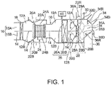
- the vehicle air conditioner for conditioning air in the vehicle cabin has a case 10.
- An upper air blowing path 12A and a lower air blowing path 12B are provided in the case 10.
- the upper air blowing path 12A is stacked on the lower air blowing path 12B and a wall 14 provided therebetween separates them from each other.
- the case 10 is provided with an outside air introduction part 16 having an upper outside air introduction port 16A and a lower outside air introduction port 16B. Outside air can be introduced to the upper air blowing path 12A via the upper outside air introduction port 16A and outside air can be introduced to the lower air blowing path 12B via the lower outside air introduction port 16B.
- An air filter 18 is provided immediately on the downstream side of the outside air introduction part 16. An upper part of the air filter 18 is positioned in the upper air blowing path 12A and a lower part of the air filter 18 is positioned in the lower air blowing path 12B.
- the case 10 further has inside air introduction ports 20A and 20B. Air in the vehicle cabin can be introduced to the upper air blowing path 12A and the lower air blowing path 12B via the inside air introduction ports 20A and 20B, respectively.
- the inside air introduction ports 20A and 20B are provided with switching doors 22A and 22B, respectively. By switching the positions of the switching doors 22A and 22B, the air flowing through the upper air blowing path 12A and the lower air blowing path 12B toward the downstream side may be one of outside air and inside air or mixture of outside air and inside air.
- the vehicle air conditioner has a blower unit 24.
- the blower unit 24 has an upper fan 24A that forms an air flow in the upper air blowing path 12A and a lower fan 24B that forms an air flow in the lower air blowing path 12B.
- a cooling heat exchanger (evaporator) 26 is provided in the case 10.
- An upper part 26A of the cooling heat exchanger 26 is positioned in the upper air blowing path 12A and a lower part 26B of the cooling heat exchanger 26 is positioned in the lower air blowing path 12B.
- the cooling heat exchanger 26 absorbs heat from air flowing therethrough and reduces the humidity of the air when the humidity of the air is high.
- a heating heat exchanger (heater core) 28 is provided in the case 10.
- An upper part 28A of the heating heat exchanger 28 is positioned in the upper air blowing path 12A and a lower part 28B of the heating heat exchanger 28 is positioned in the lower air blowing path 12B.
- the heating heat exchanger 28 heats the air flowing therethrough.
- the upper part 28A of the heating heat exchanger 28 does not occupy the all cross section of the upper air blowing path 12A.
- the region of the upper air blowing path 12A in which the heating heat exchanger 28 is not present is a bypass channel 29A that enables the air flowing through the upper air blowing path 12A to pass toward the downstream side of the heating heat exchanger 28 without passing through the upper part 28A of the heating heat exchanger 28 (by bypassing the upper part 28A).
- This bypass channel is referred to as the "upper bypass channel 29A" because it is provided in the "upper" air blowing path 12A.
- the lower part 28B of the heating heat exchanger 28 does not occupy all cross section of the lower air blowing path 12B.
- the region of the lower air blowing path 12B in which the heating heat exchanger 28 is not present is a bypass channel 29B that enables the air flowing through the lower air blowing path 12B to pass toward the downstream side of the heating heat exchanger 28 without passing through the lower part 28B of the heating heat exchanger 28 (by bypassing the lower part 28B).
- This bypass channel is referred to as the "lower bypass channel 29B" because it is provided in the "lower" air blowing path 12B.
- the upper bypass channel 29A is provided in an upper region of the upper air blowing path 12A and the lower bypass channel 29B is provided in a lower region of the lower air blowing path 12B.
- the upper air blowing path 12A and the lower air blowing path 12B are provided with an upper temperature adjusting door 30A and a lower temperature adjusting door 30B, respectively, between the cooling heat exchanger 26 and the heating heat exchanger 28.
- the upper temperature adjusting door 30A is pivotable about a pivot shaft line extending horizontally (orthogonally to the sheet of Fig. 1 ), thereby enabling the adjustment of a first bypass ratio (QUcool/QUtotal), which is the ratio of the volume of air (QUcool) passing through the upper bypass channel 29A (that is, the volume of air bypassing the heating heat exchanger 28) to the volume of air (QUtotal) (total volume) flowing out of the upper part 26A of the cooling heat exchanger 26.
- QUcool/QUtotal a first bypass ratio
- the lower temperature adjusting door 30B is pivotable about a pivot shaft line extending horizontally, thereby enabling the adjustment of a second bypass ratio (QLcool/QLtotal), which is the ratio of the volume of air (QLcool) passing through the lower bypass channel 29B (that is, the volume of air bypassing the heating heat exchanger 28) to the volume of air (QLtotal) (total volume) flowing out of the lower part 26B of the cooling heat exchanger 26.
- QLcool/QLtotal is the ratio of the volume of air (QLcool) passing through the lower bypass channel 29B (that is, the volume of air bypassing the heating heat exchanger 28) to the volume of air (QLtotal) (total volume) flowing out of the lower part 26B of the cooling heat exchanger 26.
- the dispositions of the upper bypass channel 29A and the lower bypass channel 29B are not limited to those illustrated in Fig. 1 and, as illustrated in, for example, Fig. 4 , the upper bypass channel 29A may be provided on the side of the upper air blowing path 12A and the lower bypass channel 29B may be provided on the side of the lower air blowing path 12B.
- the upper temperature adjusting door 30A is provided so as to pivot about a pivot shaft line 30AX extending in the vertical direction and the lower temperature adjusting door 30B is provided so as to pivot about a pivot shaft line 30BX extending in the vertical direction.
- an arrow U-L represents the up-down (vertical) direction.
- the air having flowed through the upper air blowing path 12A is mixed with the air having flowed through the lower air blowing path 12B.
- the air having passed through the upper part 28A of the heating heat exchanger 28 is mixed with the air having bypassed the upper part 28A of the heating heat exchanger 28 and having passed through the upper bypass channel 29A.
- the air having passed through the lower part 28B of the heating heat exchanger 28 is mixed with the air having bypassed the lower part 28B of the heating heat exchanger 28 and having passed through the lower bypass channel 29B.
- a defroster blowout passage 32 and a vent blowout passage 34 face the upper mixing space 31A.
- a foot blowout passage 36 faces the lower mixing space 31B.
- the downstream end of the defroster blowout passage 32 is connected to a defroster blowout port (not illustrated) that blows out air toward the inner surface of the front glass in the vehicle cabin.
- the downstream end of the vent blowout passage 34 is connected to a vent blowout port (not illustrated) that blows out air toward the upper bodies of occupants in the driver seat and the passenger seat (and the rear seat in some cases).
- the downstream end of the foot blowout passage 36 is connected to a foot blowout port (not illustrated) that blows out air toward the feet of occupants in the driver seat and the passenger seat (and the rear seat in some cases).
- the defroster blowout passage 32, the vent blowout passage 34, and the foot blowout passage 36 are provided with a defroster door 32D, a vent door 34D, and a foot door 36D, respectively, for adjusting the opening areas of these blowout passages 32, 34, and 36.
- the upper temperature adjusting door 30A, the lower temperature adjusting door 30B, the defroster door 32D, the vent door 34D, and the foot door 36D are driven by an actuator (not illustrated) controlled by a control unit 40 including an in-vehicle microcomputer and the like and these doors can be stopped in any pivot positon.
- the control unit 40 may be provided as a part of the vehicle air conditioner or may be provided as a part of a vehicle in which the vehicle air conditioner is installed and both forms can be adopted in the invention.
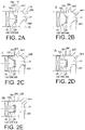
- Figs. 2(a) to 2(e) correspond to (a) to (e) in the chart of Fig. 3 , respectively.
- the horizontal axis represents the target blowout temperature (the target value of the average temperature of air flowing out of the blowout passages 32, 34, and 36 into the vehicle cabin) and the vertical axis represents the position of the upper temperature adjusting door 30A (lower temperature adjusting door 30B).
- the solid line indicated by a symbol U represents the position of the upper temperature adjusting door 30A and the dashed line indicated by a symbol L represents the position of the lower temperature adjusting door 30B.
- 100% HOT on the vertical axis in the chart of Fig. 3 represents the position in which all of the air flowing out of the upper part 26A (lower part 26B) of the cooling heat exchanger 26 flows into the upper part 28A (lower part 28B) of the heating heat exchanger 28 without passing through the upper bypass channel 29A (lower bypass channel 29B), that is, the first bypass ratio (QUcool/QUtotal) (the second bypass ratio (QLcool/QLtotal)) becomes 0%.
- 100% COOL represents the position in which all of the air flowing out of the upper part 26A (lower part 26B) of the cooling heat exchanger 26 flows through the upper bypass channel 29A (lower bypass channel 29B) and none of the air flows into the upper part 28A (lower part 28B) of the heating heat exchanger 28, that is, the first bypass ratio (QUcool/QUtotal) (the second bypass ratio (QLcool/QLtotal)) becomes 100%.
- the first bypass ratio (QUcool/QUtotal) second bypass ratio (QLcool/QLtotal)
- bypass ratio of 0% or 100% is a target control value, even if, for example, unavoidable leakage of air occurs due to a minute clearance in the vicinity of the upper temperature adjusting door 30A (lower temperature adjusting door 30B), the actual bypass ratio is assumed to be substantially 0% or 100% without taking the effect into consideration.
- the air conditioner After the air conditioner starts up, the air conditioner first operates in the defrost mode. In the range indicated by an arrow D in the lower part of the chart of Fig. 3 , the air conditioner operates in the defrost mode. In this defrost mode, as illustrated by Fig. 2 (a) and (a) in the chart of Fig. 3 , the upper temperature adjusting door 30A and the lower temperature adjusting door 30B are positioned so that all of the air having flowed out of the cooling heat exchanger 26 flows into the heating heat exchanger 28 and none of the air passes through the upper bypass channel 29A and the lower bypass channel 29B, that is, both the first bypass ratio (QUcool/QUtotal) and the second bypass ratio (QLcool/QLtotal) become zero.
- first bypass ratio QUcool/QUtotal
- QLcool/QLtotal the second bypass ratio
- the defroster door 32D is fully opened and the vent door 34D is fully closed.
- the foot door 36D is fully closed or opened with a minute opening degree. Specifically, the opening degree of the foot door 36D is approximately 0% to 10%. Accordingly, at this time, the high temperature air having flowed through the mixing chamber 31 is blown out against the inner surface of the front glass from the defroster blowout port at a large flow rate. In addition, depending on the opening degree of the foot door 36D, the high temperature air is blown out at a minute flow rate or is not blown out of the foot blowout port.
- the opening degree of the foot door 36D is the ratio (percentage) of the opening area of the foot blowout passage 36 at a certain time to the opening area of the foot blowout passage 36 when the foot blowout passage 36 is fully opened, as seen from the center axis line.
- the opening degrees of the defroster door 32D and the vent door 34D are defined similarly.
- the lower temperature adjusting door 30B is first moved while the position of the upper temperature adjusting door 30A is fixed (that is, while the first bypass ratio (QUcool/QUtotal) is maintained) to increase the second bypass ratio (QLcool/QLtotal) from zero.
- the air flowing into the mixing chamber 31 through the upper air blowing path 12A easily flows into the defroster blowout passage 32 directly, the temperature of this air is high as in (a) in the chart of Fig. 3 .
- the low temperature air having passed through the bypass channel 29B of the lower air blowing path 12B and flowed into the mixing chamber is mixed with the high temperature air having flowed out of the lower part 28B of the heating heat exchanger 28 in the lower mixing space 31B and then further mixed with the high temperature air having flowed out of the upper air blowing path 12A in the upper mixing space 31A. Accordingly, the low temperature air having passed through the bypass channel 29B of the lower air blowing path 12B and flowed into the mixing chamber 31 does not flow into the defroster blowout passage 32 with its temperature kept low. Accordingly, it is possible to prevent cool defrosting caused when the low temperature air flows into the defroster blowout passage 32.
- the operation mode of the air conditioner is switched from the defrost mode to the foot mode (also referred to as the def/foot mode).
- the air conditioner operates in the foot mode.
- the opening degree of the defroster door 32D is reduced and the foot door 36D is opened while the vent door 34D remains fully closed.
- the opening degrees of the defroster door 32D and the foot door 36D are adjusted so that approximately 80% of the total volume of air blown out to the vehicle cabin is blown out through the foot blowout port and the remaining 20% is blown out through the defroster blowout port.
- the ratio between the volumes of air blown out of the foot blowout port and the defroster blowout port may be changed as long as the volume of air blown out of the foot blowout port is larger than the volume of air blown out of the defroster blowout port.
- the movement of the upper temperature adjusting door 30A is started substantially simultaneously with the switching of the operation mode from the defrost mode to the foot mode to increase the first bypass ratio (QUcool/QUtotal). That is, after switching to the foot mode, when the temperature of air to be blown into the vehicle cabin is lowered as the air temperature in the vehicle cabin rises, both the second bypass ratio (QLcool/QLtotal) and the first bypass ratio (QUcool/QUtotal) are increased at the same time by moving both the lower temperature adjusting door 30B and the upper temperature adjusting door 30A while keeping the second bypass ratio (QLcool/QLtotal) larger than the first bypass ratio (QUcool/QUtotal) as illustrated in Fig. 2 (c) and (c) in the chart of Fig. 3 and the region to the right of (c).
- the low temperature air having passed through the bypass channel 29A of the upper air blowing path 12A flows into the upper part of the mixing chamber 31 in the foot mode, since the opening area of the defroster blowout passage 32 is small, the low temperature air does not easily enter the defroster blowout passage 32 directly and is apt to flow into the defroster blowout passage 32 after being mixed with the air having flowed out of the upper part 28A of the heating heat exchanger 28 in the upper mixing space 31A (see Fig. 1 ) of the mixing chamber 31. Accordingly, cool defrosting does not occur after switching to the foot mode.
- the operation mode of the air conditioner is switched from the foot mode to the bi-level mode.
- the air conditioner operates in the bi-level mode.
- the defroster door 32D is closed and the vent door 34D is opened while the foot door 36D remains opened.
- the opening degrees of the vent door 34D and the foot door 36D are adjusted so that, for example, approximately 60% of the total volume of air to be blown into the vehicle cabin is blown out of the foot blowout port and the remaining 40% is blown out of the vent blowout port.
- the ratio between the volumes of air blown out of the foot blowout port and the vent blowout port may be changed.
- the upper temperature adjusting door 30A and the lower temperature adjusting door 30B are moved at relatively high speed to reverse the magnitude relationship between the first bypass ratio (QUcool/QUtotal) and the second bypass ratio (QLcool/QLtotal) so that the second bypass ratio (QLcool/QLtotal) becomes smaller than the first bypass ratio (QUcool/QUtotal) (compare (c) with (d) in Fig. 2 and (c) with (d) in the chart of Fig. 3 ).
- relatively warm air flows into the lower mixing space 31B close to the foot blowout passage 36 and relatively cold air flows into the upper mixing space 31A close to the vent blowout passage 34. This achieves a comfortable air conditioning state in which the head is cooled and the feet are heated.
- both the second bypass ratio (QLcool/QLtotal) and the first bypass ratio (QUcool/QUtotal) are reduced at the same time by moving both the lower temperature adjusting door 30B and the upper temperature adjusting door 30A while keeping the second bypass ratio (QLcool/QLtotal) smaller than the first bypass ratio (QUcool/QUtotal).
- the heating startup control ends and the control mode is switched to normal temperature control.
- the switching doors 22A and 22B are switched so that, preferably, outside air (relatively low temperature and low humidity) is introduced to the upper air blowing path 12A and inside air (relatively high temperature and high humidity) is introduced to the lower air blowing path 12B.
- outside air reflatively low temperature and low humidity
- inside air reflatively high temperature and high humidity
Landscapes
- Physics & Mathematics (AREA)
- Thermal Sciences (AREA)
- Engineering & Computer Science (AREA)
- Mechanical Engineering (AREA)
- Air-Conditioning For Vehicles (AREA)
Claims (8)
- Fahrzeugklimaanlage zum Klimatisieren von Luft in einem Fahrzeuginnenraum, wobei die Fahrzeugklimaanlage Folgendes umfasst:ein Gehäuse (10);einen oberen Luftblasweg (12A) und einen unteren Luftblasweg (12B), die in dem Gehäuse (10) vorgesehen sind;eine Wand (14), die den oberen Luftblasweg (12A) und den unteren Luftblasweg (12B) voneinander trennt;einen Kühlungs-Wärmetauscher (26), der einen oberen Teil (26A) und einen unteren Teil (26B), die in dem oberen Luftblasweg (12A) bzw. dem unteren Luftblasweg (12B) positioniert sind, aufweist;einen Heiz-Wärmetauscher (28), der einen oberen Teil (28A) und einen unteren Teil (28B), die in dem oberen Luftblasweg (12A) bzw. dem unteren Luftblasweg (12B) positioniert sind, aufweist;auf einer stromabwärtigen Seite des Kühlungs-Wärmetauschers (26)einen oberen Bypasskanal (29A), der in dem oberen Luftblasweg (12A) vorgesehen ist, wobei der obere Bypasskanal (29A) ermöglicht, dass Luft, die aus dem Kühlungs-Wärmetauscher (26) herausgeströmt ist, zu der stromabwärtigen Seite strömt, indem sie den Heiz-Wärmetauscher (28) umgeht;einen unteren Bypasskanal (29B), der in dem unteren Luftblasweg (12B) vorgesehen ist, wobei der untere Bypasskanal (29B) ermöglicht, dass die Luft, die aus dem Kühlungs-Wärmetauscher (26) herausgeströmt ist, zu der stromabwärtigen Seite strömt, indem sie den Heiz-Wärmetauscher (28) umgeht;eine in dem oberen Luftblasweg (12A) zwischen dem Kühlungs-Wärmetauscher (26) und dem Heiz-Wärmetauscher (28) vorgesehene obere Temperatureinstellungsklappe (30A), wobei die obere Temperatureinstellungsklappe (30A) ein erstes Bypass-Verhältnis einstellt, das ein Verhältnis von einem Volumen von den oberen Bypasskanal (29A) durchströmender Luft zu einem Volumen von aus dem oberen Teil (26A) des Kühlungs-Wärmetauschers (26) herausgeströmter Luft ist;eine in dem unteren Luftblasweg (12B) zwischen dem Kühlungs-Wärmetauscher (26) und dem Heiz-Wärmetauscher (28) vorgesehene untere Temperatureinstellungsklappe (30B), wobei die untere Temperatureinstellungsklappe (30B) ein zweites Bypass-Verhältnis einstellt, das ein Verhältnis von einem Volumen von den unteren Bypasskanal (29B) durchströmender Luft zu einem Volumen von aus dem unteren Teil (26B) des Kühlungs-Wärmetauschers (26) herausgeströmter Luft ist;eine Mischkammer (31), zu der aus dem oberen Luftblasweg (12A) und dem unteren Luftblasweg (12B) herausgeströmte Luft strömt, wobei die Mischkammer (31) einen oberen Mischraum (31A), in dem Luft, die den oberen Teil (28A) des Heiz-Wärmetauschers (28) durchströmt hat, mit Luft, die den oberen Bypasskanal (29A) durchströmt hat, vermischt wird, und einen unteren Mischraum (31B), in dem Luft, die den unteren Teil (28B) des Heiz-Wärmetauschers (28) durchströmt hat, mit Luft, die den unteren Bypasskanal (29B) durchströmt hat, vermischt wird, aufweist;einen Defrosterausblasdurchlass (32) und einen Lüfterausblasdurchlass (34), die zu dem oberen Mischraum (31A) weisen;einen Fußraumausblasdurchlass (36), der zu dem unteren Mischraum (31B) weist;eine Defrosterklappe (32D), die eine Öffnungsfläche des Defrosterausblasdurchlasses (32) einstellt;eine Lüfterklappe (34D), die eine Öffnungsfläche des Lüfterausblasdurchlasses (34) einstellt, undeine Fußraumklappe (36D), die eine Öffnungsfläche des Fußraumausblasdurchlasses (36) einstellt; undeine Steuereinheit (40), die Betrieb mindestens der oberen Temperatureinstellungsklappe (30A), der unteren Temperatureinstellungsklappe (30B), der Defrosterklappe (32D), der Lüfterklappe (34D) und der Fußraumklappe (36D) steuert,wobei die Steuereinheit (40) die obere Temperatureinstellungsklappe (30A) und die untere Temperatureinstellungsklappe (30B) so positioniert, dass sowohl das erste Bypass-Verhältnis als auch das zweite Bypass-Verhältnis im Wesentlichen null werden, und die Defrosterklappe (32D) so steuert, dass Luft, die die Mischkammer (31) durchströmt hat, durch den Defrosterausblasdurchlass (32) strömen kann, wenn Heizungsstartsteuerung durchgeführt wird, dadurch gekennzeichnet, dass die Steuereinheit (40) die obere Temperatureinstellungsklappe (30A) und die untere Temperatureinstellungsklappe (30B) so steuert, dass die untere Temperatureinstellungsklappe (30B) zunächst dahingehend bewegt wird, das zweite Bypass-Verhältnis von null zu erhöhen, während die obere Temperatureinstellungsklappe (30A) fixiert ist, um das erste Bypass-Verhältnis im Wesentlichen auf null zu halten, wenn die Temperatur von dem Fahrzeuginnenraum bei Anstieg der Temperatur in dem Fahrzeuginnenraum zuzuführender klimatisierter Luft allmählich gesenkt wird.
- Fahrzeugklimaanlage nach Anspruch 1,
wobei die Steuereinheit (40) die Fußraumklappe (36D) so steuert, dass die Luft, die die Mischkammer (31) durchströmt hat, auch durch den Fußraumausblasdurchlass (36) strömen kann, wenn die obere Temperatureinstellungsklappe (30A) und die untere Temperatureinstellungsklappe (30B) so positioniert werden, dass sowohl das erste Bypass-Verhältnis als auch das zweite Bypass-Verhältnis im Wesentlichen null werden, und die Defrosterklappe (32D) so gesteuert wird, dass die Luft, die die Mischkammer (31) durchströmt hat, durch den Defrosterausblasdurchlass (32) strömen kann. - Fahrzeugklimaanlage nach Anspruch 1 oder 2,
wobei die Steuereinheit (40) die obere Temperatureinstellungsklappe (30A) und die untere Temperatureinstellungsklappe (30B) dahingehend steuert, das zweite Bypass-Verhältnis und das erste Bypass-Verhältnis zu vergrößern, während das zweite Bypass-Verhältnis größer als das erste Bypass-Verhältnis gehalten wird, wenn die Temperatur der dem Fahrzeuginnenraum zuzuführenden klimatisierten Luft bei Anstieg der Temperatur im Fahrzeuginnenraum aufgrund von weitergehender Heizungsstartsteuerung ansteigt. - Fahrzeugklimaanlage nach Anspruch 3,
wobei bei Anstieg der Temperatur in dem Fahrzeuginnenraum aufgrund von weitergehender Heizungsstartsteuerung die Steuereinheit (40) die Defrosterklappe (32D), die Lüfterklappe (34D) und die Fußraumklappe (36D) so steuert, dass die Luft, die die Mischkammer (31) durchströmt hat, nicht durch den Defrosterausblasdurchlass (32) strömen kann und durch den Lüfterausblasdurchlass (34) und den Fußraumausblasdurchlass (36) strömen kann, und die obere Temperatureinstellungsklappe (30A) und die untere Temperatureinstellungsklappe (30B) so steuert, dass das erste Bypass-Verhältnis größer als das zweite Bypass-Verhältnis wird. - Steuerverfahren für eine Fahrzeugklimaanlage, die einen oberen Luftblasweg (12A) und einen unteren Luftblasweg (12B), einen Kühlungs-Wärmetauscher (26), der einen oberen Teil (26A) und einen unteren Teil (26B), die in dem oberen Luftblasweg (12A) bzw. dem unteren Luftblasweg (12B) positioniert sind, aufweist, einen Heiz-Wärmetauscher (28), der einen oberen Teil (28A) und einen unteren Teil (28B), die in dem oberen Luftblasweg (12A) bzw. dem unteren Luftblasweg (12B) positioniert sind, aufweist, auf einer stromabwärtigen Seite des Kühlungs-Wärmetauschers (26) einen oberen Bypasskanal (29A), der in dem oberen Luftblasweg (12A) vorgesehen ist, wobei der obere Bypasskanal (29A) ermöglicht, dass Luft, die aus dem Kühlungs-Wärmetauscher (26) herausgeströmt ist, zu der stromabwärtigen Seite strömt, indem sie den Heiz-Wärmetauscher (28) umgeht, einen unteren Bypasskanal (29B), der in dem unteren Luftblasweg (12B) vorgesehen ist, wobei der untere Bypasskanal (29B) ermöglicht, dass die Luft, die aus dem Kühlungs-Wärmetauscher (26) herausgeströmt ist, zu der stromabwärtigen Seite strömt, indem sie den Heiz-Wärmetauscher (28) umgeht, eine in dem oberen Luftblasweg (12A) zwischen dem Kühlungs-Wärmetauscher (26) und dem Heiz-Wärmetauscher (28) vorgesehene obere Temperatureinstellungsklappe (30A), wobei die obere Temperatureinstellungsklappe (30A) ein erstes Bypass-Verhältnis einstellt, das ein Verhältnis von einem Volumen von den oberen Bypasskanal (29A) durchströmender Luft zu einem Volumen von aus dem oberen Teil (26A) des Kühlungs-Wärmetauschers (26) herausgeströmter Luft ist, eine in dem unteren Luftblasweg (12B) zwischen dem Kühlungs-Wärmetauscher (26) und dem Heiz-Wärmetauscher (28) vorgesehene untere Temperatureinstellungsklappe (30B), wobei die untere Temperatureinstellungsklappe (30B) ein zweites Bypass-Verhältnis einstellt, das ein Verhältnis von einem Volumen von den unteren Bypasskanal (29B) durchströmender Luft zu einem Volumen von aus dem unteren Teil (26B) des Kühlungs-Wärmetauschers (26) herausgeströmter Luft ist, eine Mischkammer (31), zu der aus dem oberen Luftblasweg (12A) und dem unteren Luftblasweg (12B) herausgeströmte Luft strömt, wobei die Mischkammer (31) einen oberen Mischraum (31A), in dem Luft, die den oberen Teil (28A) des Heiz-Wärmetauschers (28) durchströmt hat, mit Luft, die den oberen Bypasskanal (29A) durchströmt hat, vermischt wird, und einen unteren Mischraum (31B), in dem Luft, die den unteren Teil (28B) des Heiz-Wärmetauschers (28) durchströmt hat, mit Luft, die den unteren Bypasskanal (29B) durchströmt hat, vermischt wird, aufweist, einen Defrosterausblasdurchlass (32) und einen Lüfterausblasdurchlass (34), die zu dem oberen Mischraum (31A) weisen, einen Fußraumausblasdurchlass (36), der zu dem unteren Mischraum (31B) weist;
eine Defrosterklappe (32D), die eine Öffnungsfläche des Defrosterausblasdurchlasses (32) einstellt, eine Lüfterklappe (34D), die eine Öffnungsfläche des Lüfterausblasdurchlasses (34) einstellt, und eine Fußraumklappe (36D), die eine Öffnungsfläche des Fußraumausblasdurchlasses (36) einstellt,
wobei das Steuerverfahren die folgenden Schritte umfasst:Positionieren der oberen Temperatureinstellungsklappe (30A) und der unteren Temperatureinstellungsklappe (30B) derart, dass sowohl das erste Bypass-Verhältnis als auch das zweite Bypass-Verhältnis im Wesentlichen null werden, und Steuern der Defrosterklappe (32D) derart, dass Luft, die die Mischkammer (31) durchströmt hat, durch den Defrosterausblasdurchlass (32) strömen kann, wenn Heizungsstartsteuerung durchgeführt wird;dadurch gekennzeichnet, dass das Steuerverfahren ferner einen Schritt des Steuerns der oberen Temperatureinstellungsklappe (30A) und der unteren Temperatureinstellungsklappe (30B) derart, dass die untere Temperatureinstellungsklappe (30B) zunächst dahingehend bewegt wird, das zweite Bypass-Verhältnis von null zu erhöhen, während die obere Temperatureinstellungsklappe (30A) fixiert ist, um das erste Bypass-Verhältnis im Wesentlichen auf null zu halten, wenn die Temperatur von dem Fahrzeuginnenraum bei Anstieg der Temperatur in dem Fahrzeuginnenraum zuzuführender klimatisierter Luft allmählich gesenkt wird. - Steuerverfahren nach Anspruch 5,
wobei die Fußraumklappe (36D) so gesteuert wird, dass die Luft, die die Mischkammer (31) durchströmt hat, auch durch den Fußraumausblasdurchlass (36) strömen kann, wenn die obere Temperatureinstellungsklappe (30A) und die untere Temperatureinstellungsklappe (30B) so positioniert sind, dass das erste Bypass-Verhältnis und das zweite Bypass-Verhältnis im Wesentlichen null werden, und die Defrosterklappe (32D) so gesteuert wird, dass die Luft, die die Mischkammer (31) durchströmt hat, durch den Defrosterausblasdurchlass (32) strömen kann. - Steuerverfahren nach Anspruch 5 oder 6,
wobei die obere Temperatureinstellungsklappe (30A) und die untere Temperatureinstellungsklappe (30B) so gesteuert werden, dass das zweite Bypass-Verhältnis und das erste Bypass-Verhältnis zunehmen, während das zweite Bypass-Verhältnis größer als das erste Bypass-Verhältnis gehalten wird, wenn die Temperatur der dem Fahrzeuginnenraum zugeführten Luft bei Anstieg der Temperatur in dem Fahrzeuginnenraum aufgrund von weitergehender Heizungsstartsteuerung weiter abgesenkt wird. - Steuerverfahren nach Anspruch 7, das die Fahrzeugklimaanlage nach Anspruch 3 steuert,
wobei bei weiterem Anstieg der Temperatur in dem Fahrzeuginnenraum aufgrund von weitergehender Heizungsstartsteuerung die Defrosterklappe (32D), die Lüfterklappe (34D) und die Fußraumklappe (36D) so gesteuert werden, dass die Luft, die die Mischkammer (31) durchströmt hat, nicht durch den Defrosterausblasdurchlass (32) strömen kann und durch den Lüfterausblasdurchlass (34) und den Fußraumausblasdurchlass (36) strömen kann, und die obere Temperatureinstellungsklappe (30A) und die untere Temperatureinstellungsklappe (30B) so gesteuert werden, dass das erste Bypass-Verhältnis größer als das zweite Bypass-Verhältnis wird.
Applications Claiming Priority (2)
| Application Number | Priority Date | Filing Date | Title |
|---|---|---|---|
| JP2016099886A JP6559611B2 (ja) | 2016-05-18 | 2016-05-18 | 車両用空調装置及びその制御方法 |
| PCT/JP2017/018251 WO2017199923A1 (ja) | 2016-05-18 | 2017-05-15 | 車両用空調装置及びその制御方法 |
Publications (3)
| Publication Number | Publication Date |
|---|---|
| EP3459768A1 EP3459768A1 (de) | 2019-03-27 |
| EP3459768A4 EP3459768A4 (de) | 2020-01-15 |
| EP3459768B1 true EP3459768B1 (de) | 2020-12-30 |
Family
ID=60325272
Family Applications (1)
| Application Number | Title | Priority Date | Filing Date |
|---|---|---|---|
| EP17799347.4A Active EP3459768B1 (de) | 2016-05-18 | 2017-05-15 | Fahrzeugklimaanlage und steuerungsverfahren dafür |
Country Status (4)
| Country | Link |
|---|---|
| EP (1) | EP3459768B1 (de) |
| JP (1) | JP6559611B2 (de) |
| CN (1) | CN109153313B (de) |
| WO (1) | WO2017199923A1 (de) |
Families Citing this family (2)
| Publication number | Priority date | Publication date | Assignee | Title |
|---|---|---|---|---|
| JP7052758B2 (ja) * | 2019-03-04 | 2022-04-12 | 株式会社デンソー | 車両用空調装置 |
| US11458813B2 (en) * | 2019-12-10 | 2022-10-04 | Valeo North America, Inc. | Heating, ventilation, and air conditioning (HVAC) assembly for managing air mixing door kinematics and method for managing the same |
Family Cites Families (12)
| Publication number | Priority date | Publication date | Assignee | Title |
|---|---|---|---|---|
| JPS61205511A (ja) * | 1985-03-08 | 1986-09-11 | Nissan Motor Co Ltd | 自動車用加湿装置 |
| JPH1016531A (ja) | 1996-07-01 | 1998-01-20 | Denso Corp | 車両用空調装置 |
| JP3960020B2 (ja) * | 2001-11-22 | 2007-08-15 | 株式会社デンソー | 車両用空調装置 |
| JP2004009875A (ja) * | 2002-06-06 | 2004-01-15 | Honda Motor Co Ltd | 車両用空調装置のモード切換制御装置 |
| JP2004042803A (ja) | 2002-07-12 | 2004-02-12 | Mitsubishi Heavy Ind Ltd | 車両用空調装置 |
| JP2007131280A (ja) | 2005-11-14 | 2007-05-31 | Denso Corp | 車両用空調装置 |
| JP5569513B2 (ja) * | 2011-12-27 | 2014-08-13 | 株式会社デンソー | 車両用空調装置 |
| JP6094095B2 (ja) * | 2012-08-31 | 2017-03-15 | 株式会社デンソー | 車両用空調装置 |
| JP5949677B2 (ja) * | 2013-06-14 | 2016-07-13 | 株式会社デンソー | 車両用空調装置 |
| JP6390278B2 (ja) * | 2013-11-01 | 2018-09-19 | 株式会社デンソー | 車両用空調装置 |
| KR101534724B1 (ko) * | 2013-12-18 | 2015-07-08 | 현대자동차 주식회사 | 차량용 에어컨 시스템 제어방법 |
| JP6442961B2 (ja) * | 2014-10-01 | 2018-12-26 | 株式会社デンソー | 車両用空調装置 |
-
2016
- 2016-05-18 JP JP2016099886A patent/JP6559611B2/ja active Active
-
2017
- 2017-05-15 WO PCT/JP2017/018251 patent/WO2017199923A1/ja not_active Ceased
- 2017-05-15 EP EP17799347.4A patent/EP3459768B1/de active Active
- 2017-05-15 CN CN201780030405.1A patent/CN109153313B/zh active Active
Non-Patent Citations (1)
| Title |
|---|
| None * |
Also Published As
| Publication number | Publication date |
|---|---|
| JP6559611B2 (ja) | 2019-08-14 |
| EP3459768A1 (de) | 2019-03-27 |
| JP2017206125A (ja) | 2017-11-24 |
| CN109153313B (zh) | 2021-06-08 |
| EP3459768A4 (de) | 2020-01-15 |
| WO2017199923A1 (ja) | 2017-11-23 |
| CN109153313A (zh) | 2019-01-04 |
Similar Documents
| Publication | Publication Date | Title |
|---|---|---|
| US10017027B2 (en) | Vehicular air conditioner | |
| US10286749B2 (en) | Dual zone type air conditioner for vehicle | |
| US9616729B2 (en) | Vehicular air conditioner | |
| CN104582984B (zh) | 车辆用空调装置 | |
| US11529842B2 (en) | Vehicle air conditioning apparatus | |
| JP5721955B2 (ja) | 独立型デフロスタ吹出口空気温度および空気流量制御システム | |
| EP3459768A1 (de) | Fahrzeugklimaanlage und steuerungsverfahren dafür | |
| US20170274726A1 (en) | Air conditioning apparatus for a vehicle | |
| US11351840B2 (en) | Air conditioner for vehicle | |
| CN113748033B (zh) | 车用空调 | |
| KR102533423B1 (ko) | 차량용 공조장치 | |
| KR102739698B1 (ko) | 후석 토출구를 갖는 차량용 공조장치 | |
| KR20150129883A (ko) | 차량용 공조장치 | |
| KR20050111251A (ko) | 자동차용 공조장치 | |
| JP4111143B2 (ja) | 車両用空調装置 | |
| JP2005219574A (ja) | 車両用空調装置 | |
| KR20170040818A (ko) | 차량용 공조장치 | |
| KR102967807B1 (ko) | 차량용 공조장치 | |
| KR102192849B1 (ko) | 차량용 공조장치 | |
| KR20170040813A (ko) | 차량용 공조장치 | |
| WO2017065101A1 (ja) | 車両用空調ユニット | |
| JP2002096622A (ja) | 車両用空気調和装置 | |
| WO2023182147A1 (ja) | 車両用空調ユニット | |
| JP3119012B2 (ja) | 車両用空気調和装置 | |
| KR20080041875A (ko) | 차량용 공조장치 |
Legal Events
| Date | Code | Title | Description |
|---|---|---|---|
| STAA | Information on the status of an ep patent application or granted ep patent |
Free format text: STATUS: THE INTERNATIONAL PUBLICATION HAS BEEN MADE |
|
| PUAI | Public reference made under article 153(3) epc to a published international application that has entered the european phase |
Free format text: ORIGINAL CODE: 0009012 |
|
| STAA | Information on the status of an ep patent application or granted ep patent |
Free format text: STATUS: REQUEST FOR EXAMINATION WAS MADE |
|
| 17P | Request for examination filed |
Effective date: 20181212 |
|
| AK | Designated contracting states |
Kind code of ref document: A1 Designated state(s): AL AT BE BG CH CY CZ DE DK EE ES FI FR GB GR HR HU IE IS IT LI LT LU LV MC MK MT NL NO PL PT RO RS SE SI SK SM TR |
|
| AX | Request for extension of the european patent |
Extension state: BA ME |
|
| DAV | Request for validation of the european patent (deleted) | ||
| DAX | Request for extension of the european patent (deleted) | ||
| A4 | Supplementary search report drawn up and despatched |
Effective date: 20191213 |
|
| RIC1 | Information provided on ipc code assigned before grant |
Ipc: B60H 1/00 20060101AFI20191209BHEP |
|
| GRAP | Despatch of communication of intention to grant a patent |
Free format text: ORIGINAL CODE: EPIDOSNIGR1 |
|
| STAA | Information on the status of an ep patent application or granted ep patent |
Free format text: STATUS: GRANT OF PATENT IS INTENDED |
|
| INTG | Intention to grant announced |
Effective date: 20200728 |
|
| GRAS | Grant fee paid |
Free format text: ORIGINAL CODE: EPIDOSNIGR3 |
|
| GRAA | (expected) grant |
Free format text: ORIGINAL CODE: 0009210 |
|
| STAA | Information on the status of an ep patent application or granted ep patent |
Free format text: STATUS: THE PATENT HAS BEEN GRANTED |
|
| AK | Designated contracting states |
Kind code of ref document: B1 Designated state(s): AL AT BE BG CH CY CZ DE DK EE ES FI FR GB GR HR HU IE IS IT LI LT LU LV MC MK MT NL NO PL PT RO RS SE SI SK SM TR |
|
| REG | Reference to a national code |
Ref country code: GB Ref legal event code: FG4D |
|
| REG | Reference to a national code |
Ref country code: DE Ref legal event code: R096 Ref document number: 602017030601 Country of ref document: DE |
|
| REG | Reference to a national code |
Ref country code: AT Ref legal event code: REF Ref document number: 1349586 Country of ref document: AT Kind code of ref document: T Effective date: 20210115 |
|
| REG | Reference to a national code |
Ref country code: IE Ref legal event code: FG4D |
|
| PG25 | Lapsed in a contracting state [announced via postgrant information from national office to epo] |
Ref country code: GR Free format text: LAPSE BECAUSE OF FAILURE TO SUBMIT A TRANSLATION OF THE DESCRIPTION OR TO PAY THE FEE WITHIN THE PRESCRIBED TIME-LIMIT Effective date: 20210331 Ref country code: NO Free format text: LAPSE BECAUSE OF FAILURE TO SUBMIT A TRANSLATION OF THE DESCRIPTION OR TO PAY THE FEE WITHIN THE PRESCRIBED TIME-LIMIT Effective date: 20210330 Ref country code: FI Free format text: LAPSE BECAUSE OF FAILURE TO SUBMIT A TRANSLATION OF THE DESCRIPTION OR TO PAY THE FEE WITHIN THE PRESCRIBED TIME-LIMIT Effective date: 20201230 Ref country code: RS Free format text: LAPSE BECAUSE OF FAILURE TO SUBMIT A TRANSLATION OF THE DESCRIPTION OR TO PAY THE FEE WITHIN THE PRESCRIBED TIME-LIMIT Effective date: 20201230 |
|
| REG | Reference to a national code |
Ref country code: AT Ref legal event code: MK05 Ref document number: 1349586 Country of ref document: AT Kind code of ref document: T Effective date: 20201230 |
|
| PG25 | Lapsed in a contracting state [announced via postgrant information from national office to epo] |
Ref country code: BG Free format text: LAPSE BECAUSE OF FAILURE TO SUBMIT A TRANSLATION OF THE DESCRIPTION OR TO PAY THE FEE WITHIN THE PRESCRIBED TIME-LIMIT Effective date: 20210330 Ref country code: SE Free format text: LAPSE BECAUSE OF FAILURE TO SUBMIT A TRANSLATION OF THE DESCRIPTION OR TO PAY THE FEE WITHIN THE PRESCRIBED TIME-LIMIT Effective date: 20201230 Ref country code: LV Free format text: LAPSE BECAUSE OF FAILURE TO SUBMIT A TRANSLATION OF THE DESCRIPTION OR TO PAY THE FEE WITHIN THE PRESCRIBED TIME-LIMIT Effective date: 20201230 |
|
| REG | Reference to a national code |
Ref country code: NL Ref legal event code: MP Effective date: 20201230 |
|
| PG25 | Lapsed in a contracting state [announced via postgrant information from national office to epo] |
Ref country code: HR Free format text: LAPSE BECAUSE OF FAILURE TO SUBMIT A TRANSLATION OF THE DESCRIPTION OR TO PAY THE FEE WITHIN THE PRESCRIBED TIME-LIMIT Effective date: 20201230 |
|
| REG | Reference to a national code |
Ref country code: LT Ref legal event code: MG9D |
|
| PG25 | Lapsed in a contracting state [announced via postgrant information from national office to epo] |
Ref country code: SK Free format text: LAPSE BECAUSE OF FAILURE TO SUBMIT A TRANSLATION OF THE DESCRIPTION OR TO PAY THE FEE WITHIN THE PRESCRIBED TIME-LIMIT Effective date: 20201230 Ref country code: RO Free format text: LAPSE BECAUSE OF FAILURE TO SUBMIT A TRANSLATION OF THE DESCRIPTION OR TO PAY THE FEE WITHIN THE PRESCRIBED TIME-LIMIT Effective date: 20201230 Ref country code: PT Free format text: LAPSE BECAUSE OF FAILURE TO SUBMIT A TRANSLATION OF THE DESCRIPTION OR TO PAY THE FEE WITHIN THE PRESCRIBED TIME-LIMIT Effective date: 20210430 Ref country code: CZ Free format text: LAPSE BECAUSE OF FAILURE TO SUBMIT A TRANSLATION OF THE DESCRIPTION OR TO PAY THE FEE WITHIN THE PRESCRIBED TIME-LIMIT Effective date: 20201230 Ref country code: EE Free format text: LAPSE BECAUSE OF FAILURE TO SUBMIT A TRANSLATION OF THE DESCRIPTION OR TO PAY THE FEE WITHIN THE PRESCRIBED TIME-LIMIT Effective date: 20201230 Ref country code: LT Free format text: LAPSE BECAUSE OF FAILURE TO SUBMIT A TRANSLATION OF THE DESCRIPTION OR TO PAY THE FEE WITHIN THE PRESCRIBED TIME-LIMIT Effective date: 20201230 |
|
| PG25 | Lapsed in a contracting state [announced via postgrant information from national office to epo] |
Ref country code: AT Free format text: LAPSE BECAUSE OF FAILURE TO SUBMIT A TRANSLATION OF THE DESCRIPTION OR TO PAY THE FEE WITHIN THE PRESCRIBED TIME-LIMIT Effective date: 20201230 Ref country code: PL Free format text: LAPSE BECAUSE OF FAILURE TO SUBMIT A TRANSLATION OF THE DESCRIPTION OR TO PAY THE FEE WITHIN THE PRESCRIBED TIME-LIMIT Effective date: 20201230 |
|
| PG25 | Lapsed in a contracting state [announced via postgrant information from national office to epo] |
Ref country code: IS Free format text: LAPSE BECAUSE OF FAILURE TO SUBMIT A TRANSLATION OF THE DESCRIPTION OR TO PAY THE FEE WITHIN THE PRESCRIBED TIME-LIMIT Effective date: 20210430 |
|
| REG | Reference to a national code |
Ref country code: DE Ref legal event code: R097 Ref document number: 602017030601 Country of ref document: DE |
|
| PG25 | Lapsed in a contracting state [announced via postgrant information from national office to epo] |
Ref country code: AL Free format text: LAPSE BECAUSE OF FAILURE TO SUBMIT A TRANSLATION OF THE DESCRIPTION OR TO PAY THE FEE WITHIN THE PRESCRIBED TIME-LIMIT Effective date: 20201230 Ref country code: IT Free format text: LAPSE BECAUSE OF FAILURE TO SUBMIT A TRANSLATION OF THE DESCRIPTION OR TO PAY THE FEE WITHIN THE PRESCRIBED TIME-LIMIT Effective date: 20201230 |
|
| PLBE | No opposition filed within time limit |
Free format text: ORIGINAL CODE: 0009261 |
|
| STAA | Information on the status of an ep patent application or granted ep patent |
Free format text: STATUS: NO OPPOSITION FILED WITHIN TIME LIMIT |
|
| PG25 | Lapsed in a contracting state [announced via postgrant information from national office to epo] |
Ref country code: DK Free format text: LAPSE BECAUSE OF FAILURE TO SUBMIT A TRANSLATION OF THE DESCRIPTION OR TO PAY THE FEE WITHIN THE PRESCRIBED TIME-LIMIT Effective date: 20201230 |
|
| 26N | No opposition filed |
Effective date: 20211001 |
|
| REG | Reference to a national code |
Ref country code: CH Ref legal event code: PL |
|
| GBPC | Gb: european patent ceased through non-payment of renewal fee |
Effective date: 20210515 |
|
| PG25 | Lapsed in a contracting state [announced via postgrant information from national office to epo] |
Ref country code: ES Free format text: LAPSE BECAUSE OF FAILURE TO SUBMIT A TRANSLATION OF THE DESCRIPTION OR TO PAY THE FEE WITHIN THE PRESCRIBED TIME-LIMIT Effective date: 20201230 Ref country code: MC Free format text: LAPSE BECAUSE OF FAILURE TO SUBMIT A TRANSLATION OF THE DESCRIPTION OR TO PAY THE FEE WITHIN THE PRESCRIBED TIME-LIMIT Effective date: 20201230 Ref country code: LU Free format text: LAPSE BECAUSE OF NON-PAYMENT OF DUE FEES Effective date: 20210515 Ref country code: LI Free format text: LAPSE BECAUSE OF NON-PAYMENT OF DUE FEES Effective date: 20210531 Ref country code: CH Free format text: LAPSE BECAUSE OF NON-PAYMENT OF DUE FEES Effective date: 20210531 |
|
| REG | Reference to a national code |
Ref country code: BE Ref legal event code: MM Effective date: 20210531 |
|
| PG25 | Lapsed in a contracting state [announced via postgrant information from national office to epo] |
Ref country code: SI Free format text: LAPSE BECAUSE OF FAILURE TO SUBMIT A TRANSLATION OF THE DESCRIPTION OR TO PAY THE FEE WITHIN THE PRESCRIBED TIME-LIMIT Effective date: 20201230 |
|
| PG25 | Lapsed in a contracting state [announced via postgrant information from national office to epo] |
Ref country code: IE Free format text: LAPSE BECAUSE OF NON-PAYMENT OF DUE FEES Effective date: 20210515 Ref country code: GB Free format text: LAPSE BECAUSE OF NON-PAYMENT OF DUE FEES Effective date: 20210515 |
|
| PG25 | Lapsed in a contracting state [announced via postgrant information from national office to epo] |
Ref country code: IS Free format text: LAPSE BECAUSE OF FAILURE TO SUBMIT A TRANSLATION OF THE DESCRIPTION OR TO PAY THE FEE WITHIN THE PRESCRIBED TIME-LIMIT Effective date: 20210430 Ref country code: FR Free format text: LAPSE BECAUSE OF NON-PAYMENT OF DUE FEES Effective date: 20210531 |
|
| PG25 | Lapsed in a contracting state [announced via postgrant information from national office to epo] |
Ref country code: BE Free format text: LAPSE BECAUSE OF NON-PAYMENT OF DUE FEES Effective date: 20210531 |
|
| PG25 | Lapsed in a contracting state [announced via postgrant information from national office to epo] |
Ref country code: NL Free format text: LAPSE BECAUSE OF NON-PAYMENT OF DUE FEES Effective date: 20201230 Ref country code: CY Free format text: LAPSE BECAUSE OF FAILURE TO SUBMIT A TRANSLATION OF THE DESCRIPTION OR TO PAY THE FEE WITHIN THE PRESCRIBED TIME-LIMIT Effective date: 20201230 |
|
| PG25 | Lapsed in a contracting state [announced via postgrant information from national office to epo] |
Ref country code: SM Free format text: LAPSE BECAUSE OF FAILURE TO SUBMIT A TRANSLATION OF THE DESCRIPTION OR TO PAY THE FEE WITHIN THE PRESCRIBED TIME-LIMIT Effective date: 20201230 Ref country code: HU Free format text: LAPSE BECAUSE OF FAILURE TO SUBMIT A TRANSLATION OF THE DESCRIPTION OR TO PAY THE FEE WITHIN THE PRESCRIBED TIME-LIMIT; INVALID AB INITIO Effective date: 20170515 |
|
| P01 | Opt-out of the competence of the unified patent court (upc) registered |
Effective date: 20230629 |
|
| PG25 | Lapsed in a contracting state [announced via postgrant information from national office to epo] |
Ref country code: MK Free format text: LAPSE BECAUSE OF FAILURE TO SUBMIT A TRANSLATION OF THE DESCRIPTION OR TO PAY THE FEE WITHIN THE PRESCRIBED TIME-LIMIT Effective date: 20201230 |
|
| PG25 | Lapsed in a contracting state [announced via postgrant information from national office to epo] |
Ref country code: MT Free format text: LAPSE BECAUSE OF FAILURE TO SUBMIT A TRANSLATION OF THE DESCRIPTION OR TO PAY THE FEE WITHIN THE PRESCRIBED TIME-LIMIT Effective date: 20201230 |
|
| PGFP | Annual fee paid to national office [announced via postgrant information from national office to epo] |
Ref country code: DE Payment date: 20250513 Year of fee payment: 9 |
|
| PG25 | Lapsed in a contracting state [announced via postgrant information from national office to epo] |
Ref country code: TR Free format text: LAPSE BECAUSE OF FAILURE TO SUBMIT A TRANSLATION OF THE DESCRIPTION OR TO PAY THE FEE WITHIN THE PRESCRIBED TIME-LIMIT Effective date: 20201230 |