EP3459429A1 - Medical robotic system with coupled control modes - Google Patents
Medical robotic system with coupled control modes Download PDFInfo
- Publication number
- EP3459429A1 EP3459429A1 EP18205738.0A EP18205738A EP3459429A1 EP 3459429 A1 EP3459429 A1 EP 3459429A1 EP 18205738 A EP18205738 A EP 18205738A EP 3459429 A1 EP3459429 A1 EP 3459429A1
- Authority
- EP
- European Patent Office
- Prior art keywords
- guide tube
- instrument
- devices
- slave
- imaging system
- Prior art date
- Legal status (The legal status is an assumption and is not a legal conclusion. Google has not performed a legal analysis and makes no representation as to the accuracy of the status listed.)
- Granted
Links
- 230000033001 locomotion Effects 0.000 claims abstract description 161
- 230000004044 response Effects 0.000 claims abstract description 38
- 238000003384 imaging method Methods 0.000 claims description 202
- 230000037431 insertion Effects 0.000 claims description 38
- 238000003780 insertion Methods 0.000 claims description 37
- 238000000034 method Methods 0.000 abstract description 44
- 230000007246 mechanism Effects 0.000 description 102
- 239000012636 effector Substances 0.000 description 63
- 230000005540 biological transmission Effects 0.000 description 41
- 238000012545 processing Methods 0.000 description 33
- 210000001519 tissue Anatomy 0.000 description 27
- 230000006870 function Effects 0.000 description 22
- 230000008878 coupling Effects 0.000 description 18
- 238000010168 coupling process Methods 0.000 description 18
- 238000005859 coupling reaction Methods 0.000 description 18
- 230000000712 assembly Effects 0.000 description 17
- 238000000429 assembly Methods 0.000 description 17
- 210000000707 wrist Anatomy 0.000 description 16
- 238000010586 diagram Methods 0.000 description 15
- 238000005457 optimization Methods 0.000 description 14
- 238000001356 surgical procedure Methods 0.000 description 11
- 210000003484 anatomy Anatomy 0.000 description 9
- 239000000835 fiber Substances 0.000 description 8
- 238000002324 minimally invasive surgery Methods 0.000 description 7
- 238000005286 illumination Methods 0.000 description 6
- 230000009471 action Effects 0.000 description 5
- 238000005452 bending Methods 0.000 description 5
- 230000008569 process Effects 0.000 description 5
- 238000012546 transfer Methods 0.000 description 5
- 230000000903 blocking effect Effects 0.000 description 4
- 238000013461 design Methods 0.000 description 4
- 210000003128 head Anatomy 0.000 description 4
- 230000002262 irrigation Effects 0.000 description 4
- 238000003973 irrigation Methods 0.000 description 4
- 125000006850 spacer group Chemical group 0.000 description 4
- 210000001113 umbilicus Anatomy 0.000 description 4
- 241001631457 Cannula Species 0.000 description 3
- 101100512532 Mus musculus Atf7ip2 gene Proteins 0.000 description 3
- 101100408036 Saccharomyces cerevisiae (strain ATCC 204508 / S288c) PGU1 gene Proteins 0.000 description 3
- 101100042789 Schizosaccharomyces pombe (strain 972 / ATCC 24843) psm1 gene Proteins 0.000 description 3
- 230000008901 benefit Effects 0.000 description 3
- 230000008859 change Effects 0.000 description 3
- 238000004140 cleaning Methods 0.000 description 3
- 230000002950 deficient Effects 0.000 description 3
- 230000000881 depressing effect Effects 0.000 description 3
- 230000010354 integration Effects 0.000 description 3
- 230000003287 optical effect Effects 0.000 description 3
- 238000002604 ultrasonography Methods 0.000 description 3
- 239000013598 vector Substances 0.000 description 3
- 101100095978 Schizosaccharomyces pombe (strain 972 / ATCC 24843) psm3 gene Proteins 0.000 description 2
- 229910000831 Steel Inorganic materials 0.000 description 2
- 230000006399 behavior Effects 0.000 description 2
- 150000001875 compounds Chemical class 0.000 description 2
- 230000006378 damage Effects 0.000 description 2
- 230000000694 effects Effects 0.000 description 2
- 230000005057 finger movement Effects 0.000 description 2
- 210000004247 hand Anatomy 0.000 description 2
- 208000014674 injury Diseases 0.000 description 2
- 238000012423 maintenance Methods 0.000 description 2
- 238000013507 mapping Methods 0.000 description 2
- 230000013011 mating Effects 0.000 description 2
- 239000011159 matrix material Substances 0.000 description 2
- 238000005259 measurement Methods 0.000 description 2
- 239000013307 optical fiber Substances 0.000 description 2
- 239000004033 plastic Substances 0.000 description 2
- 229920003023 plastic Polymers 0.000 description 2
- 238000005096 rolling process Methods 0.000 description 2
- 239000004065 semiconductor Substances 0.000 description 2
- 239000010959 steel Substances 0.000 description 2
- 230000008733 trauma Effects 0.000 description 2
- 206010023230 Joint stiffness Diseases 0.000 description 1
- 239000004698 Polyethylene Substances 0.000 description 1
- 208000002847 Surgical Wound Diseases 0.000 description 1
- 206010044565 Tremor Diseases 0.000 description 1
- 206010052428 Wound Diseases 0.000 description 1
- 208000027418 Wounds and injury Diseases 0.000 description 1
- 210000001015 abdomen Anatomy 0.000 description 1
- 238000012084 abdominal surgery Methods 0.000 description 1
- 210000000436 anus Anatomy 0.000 description 1
- MPHPHYZQRGLTBO-UHFFFAOYSA-N apazone Chemical compound CC1=CC=C2N=C(N(C)C)N3C(=O)C(CCC)C(=O)N3C2=C1 MPHPHYZQRGLTBO-UHFFFAOYSA-N 0.000 description 1
- 238000001574 biopsy Methods 0.000 description 1
- 210000005013 brain tissue Anatomy 0.000 description 1
- 238000004364 calculation method Methods 0.000 description 1
- 230000000112 colonic effect Effects 0.000 description 1
- 238000004891 communication Methods 0.000 description 1
- 230000000295 complement effect Effects 0.000 description 1
- 238000013016 damping Methods 0.000 description 1
- 238000013500 data storage Methods 0.000 description 1
- 230000003247 decreasing effect Effects 0.000 description 1
- 239000002274 desiccant Substances 0.000 description 1
- 238000006073 displacement reaction Methods 0.000 description 1
- 210000003717 douglas' pouch Anatomy 0.000 description 1
- 210000000613 ear canal Anatomy 0.000 description 1
- 229920001746 electroactive polymer Polymers 0.000 description 1
- 238000002674 endoscopic surgery Methods 0.000 description 1
- 238000001839 endoscopy Methods 0.000 description 1
- 230000007613 environmental effect Effects 0.000 description 1
- 210000003238 esophagus Anatomy 0.000 description 1
- 239000003000 extruded plastic Substances 0.000 description 1
- 238000001914 filtration Methods 0.000 description 1
- 239000012530 fluid Substances 0.000 description 1
- 238000002594 fluoroscopy Methods 0.000 description 1
- 230000002496 gastric effect Effects 0.000 description 1
- 210000004704 glottis Anatomy 0.000 description 1
- 230000000977 initiatory effect Effects 0.000 description 1
- 230000002452 interceptive effect Effects 0.000 description 1
- 210000003127 knee Anatomy 0.000 description 1
- 238000002357 laparoscopic surgery Methods 0.000 description 1
- 230000000670 limiting effect Effects 0.000 description 1
- 238000002595 magnetic resonance imaging Methods 0.000 description 1
- 210000003205 muscle Anatomy 0.000 description 1
- 239000002985 plastic film Substances 0.000 description 1
- -1 polyethylene Polymers 0.000 description 1
- 229920000573 polyethylene Polymers 0.000 description 1
- 238000003825 pressing Methods 0.000 description 1
- 238000011084 recovery Methods 0.000 description 1
- 230000002829 reductive effect Effects 0.000 description 1
- 238000002432 robotic surgery Methods 0.000 description 1
- 239000000523 sample Substances 0.000 description 1
- 230000035807 sensation Effects 0.000 description 1
- 230000001953 sensory effect Effects 0.000 description 1
- 229910001285 shape-memory alloy Inorganic materials 0.000 description 1
- 238000004088 simulation Methods 0.000 description 1
- 239000007921 spray Substances 0.000 description 1
- 230000003068 static effect Effects 0.000 description 1
- 239000003356 suture material Substances 0.000 description 1
- 238000002560 therapeutic procedure Methods 0.000 description 1
- 210000000115 thoracic cavity Anatomy 0.000 description 1
- 230000000451 tissue damage Effects 0.000 description 1
- 231100000827 tissue damage Toxicity 0.000 description 1
- 238000013334 tissue model Methods 0.000 description 1
- 238000012549 training Methods 0.000 description 1
- 210000003708 urethra Anatomy 0.000 description 1
- 210000001215 vagina Anatomy 0.000 description 1
- 230000000007 visual effect Effects 0.000 description 1
- 238000012800 visualization Methods 0.000 description 1
- XLYOFNOQVPJJNP-UHFFFAOYSA-N water Substances O XLYOFNOQVPJJNP-UHFFFAOYSA-N 0.000 description 1
- 210000003857 wrist joint Anatomy 0.000 description 1
Images


Classifications
-
- A—HUMAN NECESSITIES
- A61—MEDICAL OR VETERINARY SCIENCE; HYGIENE
- A61B—DIAGNOSIS; SURGERY; IDENTIFICATION
- A61B34/00—Computer-aided surgery; Manipulators or robots specially adapted for use in surgery
- A61B34/30—Surgical robots
- A61B34/37—Master-slave robots
-
- A—HUMAN NECESSITIES
- A61—MEDICAL OR VETERINARY SCIENCE; HYGIENE
- A61B—DIAGNOSIS; SURGERY; IDENTIFICATION
- A61B1/00—Instruments for performing medical examinations of the interior of cavities or tubes of the body by visual or photographical inspection, e.g. endoscopes; Illuminating arrangements therefor
- A61B1/00064—Constructional details of the endoscope body
- A61B1/00071—Insertion part of the endoscope body
- A61B1/0008—Insertion part of the endoscope body characterised by distal tip features
- A61B1/00087—Tools
-
- A—HUMAN NECESSITIES
- A61—MEDICAL OR VETERINARY SCIENCE; HYGIENE
- A61B—DIAGNOSIS; SURGERY; IDENTIFICATION
- A61B1/00—Instruments for performing medical examinations of the interior of cavities or tubes of the body by visual or photographical inspection, e.g. endoscopes; Illuminating arrangements therefor
- A61B1/005—Flexible endoscopes
- A61B1/0051—Flexible endoscopes with controlled bending of insertion part
- A61B1/0055—Constructional details of insertion parts, e.g. vertebral elements
-
- A—HUMAN NECESSITIES
- A61—MEDICAL OR VETERINARY SCIENCE; HYGIENE
- A61B—DIAGNOSIS; SURGERY; IDENTIFICATION
- A61B34/00—Computer-aided surgery; Manipulators or robots specially adapted for use in surgery
- A61B34/30—Surgical robots
-
- A—HUMAN NECESSITIES
- A61—MEDICAL OR VETERINARY SCIENCE; HYGIENE
- A61B—DIAGNOSIS; SURGERY; IDENTIFICATION
- A61B34/00—Computer-aided surgery; Manipulators or robots specially adapted for use in surgery
- A61B34/70—Manipulators specially adapted for use in surgery
- A61B34/71—Manipulators operated by drive cable mechanisms
-
- A—HUMAN NECESSITIES
- A61—MEDICAL OR VETERINARY SCIENCE; HYGIENE
- A61B—DIAGNOSIS; SURGERY; IDENTIFICATION
- A61B34/00—Computer-aided surgery; Manipulators or robots specially adapted for use in surgery
- A61B34/70—Manipulators specially adapted for use in surgery
- A61B34/72—Micromanipulators
-
- A—HUMAN NECESSITIES
- A61—MEDICAL OR VETERINARY SCIENCE; HYGIENE
- A61B—DIAGNOSIS; SURGERY; IDENTIFICATION
- A61B90/00—Instruments, implements or accessories specially adapted for surgery or diagnosis and not covered by any of the groups A61B1/00 - A61B50/00, e.g. for luxation treatment or for protecting wound edges
- A61B90/36—Image-producing devices or illumination devices not otherwise provided for
- A61B90/361—Image-producing devices, e.g. surgical cameras
-
- A—HUMAN NECESSITIES
- A61—MEDICAL OR VETERINARY SCIENCE; HYGIENE
- A61B—DIAGNOSIS; SURGERY; IDENTIFICATION
- A61B90/00—Instruments, implements or accessories specially adapted for surgery or diagnosis and not covered by any of the groups A61B1/00 - A61B50/00, e.g. for luxation treatment or for protecting wound edges
- A61B90/36—Image-producing devices or illumination devices not otherwise provided for
- A61B90/37—Surgical systems with images on a monitor during operation
-
- A—HUMAN NECESSITIES
- A61—MEDICAL OR VETERINARY SCIENCE; HYGIENE
- A61B—DIAGNOSIS; SURGERY; IDENTIFICATION
- A61B1/00—Instruments for performing medical examinations of the interior of cavities or tubes of the body by visual or photographical inspection, e.g. endoscopes; Illuminating arrangements therefor
- A61B1/00163—Optical arrangements
- A61B1/00193—Optical arrangements adapted for stereoscopic vision
-
- A—HUMAN NECESSITIES
- A61—MEDICAL OR VETERINARY SCIENCE; HYGIENE
- A61B—DIAGNOSIS; SURGERY; IDENTIFICATION
- A61B1/00—Instruments for performing medical examinations of the interior of cavities or tubes of the body by visual or photographical inspection, e.g. endoscopes; Illuminating arrangements therefor
- A61B1/012—Instruments for performing medical examinations of the interior of cavities or tubes of the body by visual or photographical inspection, e.g. endoscopes; Illuminating arrangements therefor characterised by internal passages or accessories therefor
- A61B1/018—Instruments for performing medical examinations of the interior of cavities or tubes of the body by visual or photographical inspection, e.g. endoscopes; Illuminating arrangements therefor characterised by internal passages or accessories therefor for receiving instruments
-
- A—HUMAN NECESSITIES
- A61—MEDICAL OR VETERINARY SCIENCE; HYGIENE
- A61B—DIAGNOSIS; SURGERY; IDENTIFICATION
- A61B17/00—Surgical instruments, devices or methods, e.g. tourniquets
- A61B17/00234—Surgical instruments, devices or methods, e.g. tourniquets for minimally invasive surgery
- A61B2017/00238—Type of minimally invasive operation
- A61B2017/00278—Transorgan operations, e.g. transgastric
-
- A—HUMAN NECESSITIES
- A61—MEDICAL OR VETERINARY SCIENCE; HYGIENE
- A61B—DIAGNOSIS; SURGERY; IDENTIFICATION
- A61B17/00—Surgical instruments, devices or methods, e.g. tourniquets
- A61B2017/00681—Aspects not otherwise provided for
- A61B2017/00694—Aspects not otherwise provided for with means correcting for movement of or for synchronisation with the body
-
- A—HUMAN NECESSITIES
- A61—MEDICAL OR VETERINARY SCIENCE; HYGIENE
- A61B—DIAGNOSIS; SURGERY; IDENTIFICATION
- A61B17/00—Surgical instruments, devices or methods, e.g. tourniquets
- A61B17/34—Trocars; Puncturing needles
- A61B17/3417—Details of tips or shafts, e.g. grooves, expandable, bendable; Multiple coaxial sliding cannulas, e.g. for dilating
- A61B17/3421—Cannulas
- A61B2017/3445—Cannulas used as instrument channel for multiple instruments
- A61B2017/3447—Linked multiple cannulas
-
- A—HUMAN NECESSITIES
- A61—MEDICAL OR VETERINARY SCIENCE; HYGIENE
- A61B—DIAGNOSIS; SURGERY; IDENTIFICATION
- A61B34/00—Computer-aided surgery; Manipulators or robots specially adapted for use in surgery
- A61B34/20—Surgical navigation systems; Devices for tracking or guiding surgical instruments, e.g. for frameless stereotaxis
- A61B2034/2046—Tracking techniques
- A61B2034/2061—Tracking techniques using shape-sensors, e.g. fiber shape sensors with Bragg gratings
-
- A—HUMAN NECESSITIES
- A61—MEDICAL OR VETERINARY SCIENCE; HYGIENE
- A61B—DIAGNOSIS; SURGERY; IDENTIFICATION
- A61B34/00—Computer-aided surgery; Manipulators or robots specially adapted for use in surgery
- A61B34/30—Surgical robots
- A61B2034/301—Surgical robots for introducing or steering flexible instruments inserted into the body, e.g. catheters or endoscopes
-
- A—HUMAN NECESSITIES
- A61—MEDICAL OR VETERINARY SCIENCE; HYGIENE
- A61B—DIAGNOSIS; SURGERY; IDENTIFICATION
- A61B34/00—Computer-aided surgery; Manipulators or robots specially adapted for use in surgery
- A61B34/30—Surgical robots
- A61B2034/305—Details of wrist mechanisms at distal ends of robotic arms
- A61B2034/306—Wrists with multiple vertebrae
-
- A—HUMAN NECESSITIES
- A61—MEDICAL OR VETERINARY SCIENCE; HYGIENE
- A61B—DIAGNOSIS; SURGERY; IDENTIFICATION
- A61B34/00—Computer-aided surgery; Manipulators or robots specially adapted for use in surgery
- A61B34/20—Surgical navigation systems; Devices for tracking or guiding surgical instruments, e.g. for frameless stereotaxis
Definitions
- the present invention generally relates to medical robotic systems and in particular, to a medical robotic system providing coupled control modes.
- Minimally invasive surgery is known under various names (e.g., endoscopy, laparoscopy, arthroscopy, endovascular, keyhole, etc.), often specific to the anatomical area in which work is done.
- Such surgery includes the use of both hand-held and teleoperated/telemanipulated/telepresence (robot assisted/telerobotics) equipment, such as the da Vinci® Surgical System made by Intuitive Surgical, Inc. of Sunnyvale, California. Both diagnostic (e.g., biopsy) and therapeutic procedures (“medical procedures”) are done. Instruments may be inserted into a patient percutaneously via surgical incision or via natural orifice.
- a new, experimental minimally invasive surgery variation is Natural Orifice Transluminal Endoscopic Surgery (NOTES), in which instruments enter via a natural orifice (e.g., mouth, nostril, ear canal, anus, vagina, urethra) and continue to a surgical site via a transluminal incision (e.g., in a gastric or colonic wall) within the body.
- NOTES Natural Orifice Transluminal Endoscopic Surgery
- a natural orifice e.g., mouth, nostril, ear canal, anus, vagina, urethra
- a transluminal incision e.g., in a gastric or colonic wall
- teleoperative surgery using the da Vinci® Surgical System provides great benefits over, for instance, many hand-held procedures, for some patients and for some anatomical areas the da Vinci® Surgical System may be unable to effectively access a surgical site.
- further reducing the size and number of incisions generally aids patient recovery and helps reduce patient trauma and discomfort
- Various slave manipulators are provided in such medical robotic systems to perform useful functions, such as manipulating instruments to perform medical procedures on a patient, positioning and orienting imaging systems such as endoscopic imaging devices to capture images of the instruments' working ends, and delivering the working ends of the instruments and an image capturing end of the imaging system to a work site in the patient.
- the delivery of the working and image capturing ends of the instruments and imaging system (“medical devices") uses one or more guide tubes and structures that hold and manipulate the guide tube(s).
- master manipulators are used as input devices to track the motion of their operator's hands and to provide appropriate haptic feedback to the operator indicative of the state of their associated slave manipulators.
- the slave and master manipulators (“robotic manipulators”) may be designed with different workspaces and dexterities.
- the reachable workspace of a medical device that is being manipulated by a slave manipulator is the set of points and orientations in space that its distal tip (e.g., working or image capturing end) can reach.
- the dexterous workspace of the medical device's distal tip generally identifies the set of points in space that can be reached by primarily changing its orientation (e.g., changing the position of a wrist joint that orients the distal tip).
- dexterity is a measure of the capability of a robotic manipulator to control the position (in a limited manner) and orientation of the working end of its associated medical device. Further, it relates the joint degrees of freedom (i.e.
- the dexterous workspace is generally a subset of the reachable workspace.
- instrument slave manipulators are generally designed to optimize their dexterity, even at the expense of sacrificing their overall reachable workspace.
- a base manipulator such as a patient side cart
- a large reachable workspace may be used to deliver the instrument and imaging system slave manipulators near the entry apertures (e.g., minimally invasive incisions or natural orifices) in the patient body.
- the guide tube serves as a secondary base since movement of the guide tube in this case effectively moves all of the instruments and the imaging system disposed therein.
- the instrument and imaging system slave manipulators may then finally deliver the working and image capturing ends of their respective medical devices to the work site (e.g., target anatomy) in the patient.
- the overall capability of a medical robotic system is achieved by a balance between the workspace and dexterity of all the robotic manipulators that constitute it.
- the differences in the individual capabilities of each manipulator have to be clear and well understood by the user in order to effectively utilize the system. It is in general difficult for the user to select which manipulator to control from the console and how to move it in order to achieve a desired "working configuration" of their respective medical devices inside the patient, with the instruments' working ends having the best possible dexterity and reach, while the capturing end of the imaging system is positioned in such a way to provide good visualization of the medical procedure being performed at the work site without interfering with the instruments' movements.
- the system with the capability of performing secondary or coupled control movements, e.g., for the camera manipulator and the base manipulator (guide tube manipulator and/or manipulator for moving the setup arms and or support for the patient side support system), so as not to distract the user from performing the medical procedure at the time using the surgical instruments.
- secondary or coupled control movements e.g., for the camera manipulator and the base manipulator (guide tube manipulator and/or manipulator for moving the setup arms and or support for the patient side support system), so as not to distract the user from performing the medical procedure at the time using the surgical instruments.
- the number of degrees of freedom (DOFs) is the number of independent variables that uniquely identify the pose/configuration of a system. Since robotic manipulators are kinematic chains that map the (input) joint space into the (output) Cartesian space, the notion of DOF can be expressed in any of these two spaces.
- the set of joint DOFs is the set of joint variables for all the independently controlled joints.
- joints are mechanisms that provide a single translational (prismatic joints) or rotational (revolute joints) DOF. Any mechanism that provides more than one DOF motion is considered, from a kinematic modeling perspective, as two or more separate joints.
- the set of Cartesian DOFs is usually represented by the three translational (position) variables (e.g., surge, heave, sway) and by the three rotational (orientation) variables (e.g. Euler angles or roll/pitch/yaw angles) that describe the position and orientation of an end effector (or tip) frame with respect to a given reference Cartesian frame.
- position e.g., surge, heave, sway
- orientation e.g. Euler angles or roll/pitch/yaw angles
- a planar mechanism with an end effector mounted on two independent and perpendicular rails has the capability of controlling the x/y position within the area spanned by the two rails (prismatic DOFs). If the end effector can be rotated around an axis perpendicular to the plane of the rails, then there are then three input DOFs (the two rail positions and the yaw angle) that correspond to three output DOFs (the x/y position and the orientation angle of the end effector).
- the number of Cartesian DOFs is at most six, a condition in which all the translational and orientational variables arc independently controlled, the number of joint DOFs is generally the result of design choices that involve considerations of the complexity of the mechanism and the task specifications. Accordingly, the number of joint DOFs can be more than, equal to, or less than six. For non-redundant kinematic chains, the number of independently controlled joints is equal to the degree of mobility for the end effector frame.
- the end effector frame will have an equal number of DOFs (except when in singular configurations) in Cartesian space that will correspond to a combination of translational (x/y/z position) and rotational (roll/pitch/yaw orientation angle) motions.
- a single DOF change in joint space may result in a motion that combines changes in the Cartesian translational and orientational variables of the frame attached to the distal tip of one of the links (the frame at the distal tip both rotates and translates through space).
- Kinematics describes the process of converting from one measurement space to another. For example, using joint space measurements to determine the Cartesian space position and orientation of a reference frame at the tip of a kinematic chain is "forward" kinematics.
- Cartesian space position and orientation for the reference frame at the tip of a kinematic chain to determine the required joint positions is "inverse" kinematics. If there are any revolute joints, kinematics involves nonlinear (trigonometric) functions.
- An object of aspects of the invention is to provide coupled control modes in which one or more devices may be directly controlled to achieve a primary objective and one or more other devices may be indirectly controlled to achieve secondary objectives.
- one aspect is a robotic system comprising: a first instrument; a base that the first instrument is coupled to so that the first instrument moves when the base moves; a base controller means for causing the base to be moved so as to optimize a workspace of the first instrument as the first instrument moves; and a first instrument controller for moving the first instrument according to commanded movement while compensating for movement of the base.
- Another aspect is a method for controlling movement of one or more instruments coupled to a base so that the instruments move as the base moves, the method comprising: commanding manipulation of the base so as to optimize an operable workspace of a first instrument; and commanding manipulation of the first instrument according to commanded movement while compensating for movement of the base.
- Another aspect is a robotic system comprising: a plurality of devices each manipulated by a corresponding one of a plurality of slave manipulators; a master input device; and means for commanding the plurality of slave manipulators to move their respective devices in a common degree-of-freedom direction in response to movement of the master input device.
- Another aspect is a method for retracting a plurality of devices back into a guide tube, the method comprising: receiving a retraction command from an input device; retracting a plurality of devices extending beyond a distal end of a guide tube back together towards the guide tube in response to the retraction command; and driving the plurality of devices to retraction configurations so that each of the plurality of devices may freely enter the guide tube.
- Still another aspect is a robotic system comprising: a plurality of instruments each manipulated by a corresponding one of a plurality of slave manipulators; an imaging system manipulated by an imaging system manipulator; a master input device; and means for commanding the plurality of slave manipulators to move the plurality of instruments in response to movement of the imaging system when the imaging system manipulator moves in response to movement of the master input device.
- Yet another aspect is a method for coupling control of an imaging system with other devices in a robotic system, the method comprising: causing a plurality of instruments to move so as to follow an image capturing end of an imaging system as the imaging system moves in response to movement of a master input device.
- spatially relative terms such as “beneath”, “below”, “lower”, “above”, “upper”, “proximal”, “distal”, and the like-may be used to describe one element's or feature's relationship to another element or feature as illustrated in the figures.
- These spatially relative terms are intended to encompass different positions and orientations of the device in use or operation in addition to the position and orientation shown in the figures. For example, if the device in the figures is turned over, elements described as “below” or “beneath” other elements or features would then be “above” or “over” the other elements or features.
- the exemplary term “below” can encompass both positions and orientations of above and below.
- the device may be otherwise oriented (rotated 90 degrees or at other orientations), and the spatially relative descriptors used herein interpreted accordingly. Likewise, descriptions of movement along and around various axes includes various special device positions and orientations.
- the singular forms "a”, “an”, and “the” are intended to include the plural forms as well, unless the context indicates otherwise.
- the terms “comprises”, “comprising”, “includes”, and the like specify the presence of stated features, steps, operations, elements, and/or components but do not preclude the presence or addition of one or more other features, steps, operations, elements, components, and/or groups. Components described as coupled may be electrically or mechanically directly coupled, or they may be indirectly coupled via one or more intermediate components.
- Telemanipulation and like terms generally refer to an operator manipulating a master device (e.g., an input kinematic chain) in a relatively natural way (e.g., a natural hand or finger movement), whereupon the master device movements are made into commands that are processed and transmitted in real time to a slave device (e.g., an output kinematic chain) that reacts nearly instantaneously to the commands and to environmental forces.
- a master device e.g., an input kinematic chain
- a relatively natural way e.g., a natural hand or finger movement
- a slave device e.g., an output kinematic chain
- An end effector is the part of the minimally invasive surgical instrument or assembly that performs a specific surgical function (e.g., forceps/graspers, needle drivers, scissors, electrocautery hooks, staplers, clip appliers/removers, etc.).
- Many end effectors have a single DOF (e.g., graspers that open and close).
- the end effector may be coupled to the surgical instrument body with a mechanism that provides one or more additional DOFs, such as "wrist" type mechanisms. Examples of such mechanisms are shown in U.S. Patent No. 6,371,952 (Madhani et al.
- descriptions of positioning and orienting an end effector include positioning and orienting the tip of a surgical instrument that does not have an end effector.
- a description that addresses the reference frame for a tip of an end effector should also be read to include the reference frame of the tip of a surgical instrument that does not have an end effector.
- imaging system and the like as used herein should be broadly construed to include both image capture components and combinations of image capture components with associated circuitry and hardware, within the context of the aspects and embodiments being described.
- Such endoscopic imaging systems include systems with distally positioned image sensing chips and associated circuits that relay captured image data via a wired or wireless connection to outside the body.
- Such endoscopic imaging systems also include systems that relay images for capture outside the body (e.g., by using rod lenses or fiber optics).
- a direct view optical system the endoscopic image is viewed directly at an eyepiece
- An example of a distally positioned semiconductor stereoscopic imaging system is described in U.S. Patent Application No. 11/614,661 "Stereoscopic Endoscope" (Shafer et al.), which is incorporated by reference.
- Illumination for endoscopic imaging is typically represented in the drawings by a single illumination port. It should be understood that these depictions are exemplary. The sizes, positions, and numbers of illumination ports may vary. Illumination ports are typically arranged on multiple sides of the imaging apertures, or completely surrounding the imaging apertures, to minimize deep shadows.
- cannulas are typically used to prevent a surgical instrument or guide tube from rubbing on patient tissue. Cannulas may be used for both incisions and natural orifices. For situations in which an instrument or guide tube does not frequently translate or rotate relative to its insertion (longitudinal) axis, a cannula may not be used. For situations that require insufflation, the cannula may include a seal to prevent excess insufflation gas leakage past the instrument or guide tube. For example, for thoracic surgery that does not require insufflation, the cannula seal may be omitted, and if instruments or guide tube insertion axis movement is minimal, then the cannula itself may be omitted.
- a rigid guide tube may function as a cannula in some configurations for instruments that are inserted relative to the guide tube.
- Cannulas and guide tubes may be, e.g., steel or extruded plastic.
- Plastic which is less expensive than steel, may be suitable for one-time use.
- a segment or an instrument or guide tube may be a continuously curving flexible structure, such as one based on a helical wound coil or on tubes with various segments removed (e.g., kerf-type cuts).
- the flexible part may be made of a series of short, pivotally connected segments (“vertebrae") that provide a snake-like approximation of a continuously curving structure.
- Instrument and guide tube structures may include those in U.S. Patent Application Pub. No. US 2004/0138700 (Cooper et al. ), which is incorporated by reference.
- the figures and associated descriptions generally show only two segments of instruments and guide tubes, termed proximal (closer to the transmission mechanism; farther from the surgical site) and distal (farther from the transmission mechanism; closer to the surgical site).
- the instruments and guide tubes may be divided into three or more segments, each segment being rigid, passively flexible, or actively flexible. Flexing and bending as described for a distal segment, a proximal segment, or an entire mechanism also apply to intermediate segments that have been omitted for clarity. For instance, an intermediate segment between proximal and distal segments may bend in a simple or compound curve. Flexible segments may be various lengths.
- Segments with a smaller outside diameter may have a smaller minimum radius of curvature while bending than segments with a larger outside diameter.
- unacceptably high cable friction or binding limits minimum radius of curvature and the total bend angle while bending.
- the guide tube's (or any joint's) minimum bend radius is such that it does not kink or otherwise inhibit the smooth motion of the inner surgical instrument's mechanism.
- Flexible components may be, for example, up to approximately four feet in length and approximately 0.6 inches in diameter. Other lengths and diameters (e.g., shorter, smaller) and the degree of flexibility for a specific mechanism may be determined by the target anatomy for which the mechanism has been designed.
- a distal segment of an instrument or guide tube is flexible, and the proximal segment is rigid. In other instances, the entire segment of the instrument or guide tube that is inside the patient is flexible. In still other instances, an extreme distal segment may be rigid, and one or more other proximal segments are flexible.
- the flexible segments may be passive or they may be actively controllable (“steerable”). Such active control may be done using, for example, sets of opposing cables (e.g., one set controlling "pitch” and an orthogonal set controlling "yaw”; three cables can be used to perform similar action).
- control elements such as small electric or magnetic actuators, shape memory alloys, electroactive polymers ("artificial muscle”), pneumatic or hydraulic bellows or pistons, and the like may be used.
- a segment of an instrument or guide tube is fully or partially inside another guide tube
- various combinations of passive and active flexibility may exist.
- an actively flexible instrument inside a passively flexible guide tube may exert sufficient lateral force to flex the surrounding guide tube.
- an actively flexible guide tube may flex a passively flexible instrument inside it.
- Actively flexible segments of guide tubes and instruments may work in concert.
- control cables placed farther from the center longitudinal axis may provide a mechanical advantage over cables placed nearer to the center longitudinal axis, depending on compliance considerations in the various designs.
- the flexible segment's compliance may vary from being almost completely flaccid (small internal frictions exist) to being substantially rigid.
- the compliance is controllable.
- a segment or all of a flexible segment of an instrument or guide tube can be made substantially (i.e., effectively but not infinitely) rigid (the segment is "rigidizable” or “lockable”).
- the lockable segment may be locked in a straight, simple curve or in a compound curve shape. Locking may be accomplished by applying tension to one or more cables that run longitudinally along the instrument or guide tube that is sufficient to cause friction to prevent adjacent vertebrae from moving.
- the cable or cables may run through a large, central hole in each vertebra or may run through smaller holes near the vertebra's outer circumference.
- the drive element of one or more motors that move one or more control cables may be soft-locked in position (e.g., by servocontrol) to hold the cables in position and thereby prevent instrument or guide tube movement, thus locking the vertebrae in place. Keeping a motor drive element in place may be done to effectively keep other movable instrument and guide tube components in place as well.
- stiffness under servocontrol although effective, is generally less than the stiffness that may be obtained with braking placed directly on joints, such as the braking used to keep passive setup joints in place. Cable stiffness generally dominates because it is generally less than servosystem or braked joint stiffness.
- the compliance of the flexible segment may be continuously varied between flaccid and rigid states. For example, locking cable tension can be increased to increase stiffness but without locking the flexible segment in a rigid state. Such intermediate compliance may allow for telesurgical operation while reducing tissue trauma that may occur due to movements caused by reactive forces from the surgical site.
- Suitable bend sensors incorporated into the flexible segment allow the telesurgical system to determine instrument and/or guide tube position as it bends.
- U.S. Patent Application Pub. No. US 2006/0013523 (Childers et al. ), which is incorporated by reference, discloses a fiber optic position shape sensing device and method.
- U.S. Patent Application No. 11/491,384 which is incorporated by reference, discloses fiber optic bend sensors (e.g., fiber Bragg gratings) used in the control of such segments and flexible devices.
- a surgeon's inputs to control aspects of the minimally invasive surgical instrument assemblies, instruments, and end effectors as described herein are generally done using an intuitive, camera referenced control interface.
- the da Vinci® Surgical System includes a Surgeon's console with such a control interface, which may be modified to control aspects described herein.
- the surgeon manipulates one or more master manual input mechanisms having, e.g., 6 DOFs to control the slave instrument assembly and instrument.
- the input mechanisms include a finger-operated grasper to control one or more end effector DOFs (e.g., closing grasping jaws).
- Intuitive control is provided by orienting the relative positions of the end effectors and the endoscopic imaging system with the positions of the surgeon's input mechanisms and image output display.
- This orientation allows the surgeon to manipulate the input mechanisms and end effector controls as if viewing the surgical work site in substantially true presence.
- This teleoperation true presence means that the surgeon views an image from a perspective that appears to be that of an operator directly viewing and working at the surgical site.
- U.S. Patent No. 6,671,581 (Niemeyer et al. ), which is incorporated by reference, contains further information on camera referenced control in a minimally invasive surgical apparatus.
- FIG 1 is a schematic view that illustrates aspects of a robot-assisted (telemanipulative) minimally invasive surgical system 2100 in which instruments are inserted in a patient through a single entry aperture through a guide tube.
- This system's general architecture is similar to the architecture of other such systems such as Intuitive Surgical, Inc.'s da Vinci® Surgical System and the Zeus® Surgical System.
- the three main components are a surgeon's console 2102, a patient side support system 2104, and a video system 2106, all interconnected 2108 by wired or wireless connections as shown.
- the surgeon's console 2102 includes, e.g., hand-operable, multiple DOF mechanical input (“master”) devices 203, 204 and foot pedals 215, 217 that allow the surgeon to manipulate the surgical instruments, guide tubes, and imaging system (“slave”) devices as described herein. These input devices may in some aspects provide haptic feedback from the instruments and instrument assembly components to the surgeon. Buttons 205, 207 are provided on the hand-operable input devices 203, 204 for switching functions as described herein or for other operational purposes.
- Console 2102 also includes a stereoscopic video output display 201 positioned such that images on the display are generally focused at a distance that corresponds to the surgeon's hands working behind/below the display screen.
- a processor 220 in communication with other components of the console via bus 210 performs various functions in the system 2100.
- One important function that it performs is to implement the various controllers described herein to translate and transfer the mechanical motion of input devices through control signals so that the Surgeon can effectively manipulate and otherwise move devices, such as the surgical instruments, an imaging system, and one or more guide tubes, that are selectively associated with the input devices at the time.
- the processor 220 may be implemented in practice by any combination of hardware, software and firmware. Also, its functions as described herein may be performed by one unit or divided up among different components, each of which may be implemented in turn by any combination of hardware, software and firmware.
- processor 220 may also comprise a number of subunits distributed throughout the system. These aspects are discussed more fully in U.S. Patent No. 6,671,581 , which is incorporated by reference above.
- the patient side support system 2104 includes a floor-mounted structure 2110, or alternately a ceiling mounted structure 2112 as shown by the alternate lines.
- the structure 2110 may be movable or fixed (e.g., to the floor, ceiling, or other equipment such as an operating table).
- a set-up arm assembly 2114 is a modified da Vinci® Surgical System arm assembly.
- the arm assembly 2114 includes two illustrative passive rotational setup joints 2114a,2114b, which allow manual positioning of the coupled links when their brakes are released.
- a passive prismatic setup joint (not shown) between the arm assembly and the structure 2110 may be used to allow for large vertical adjustments.
- a guide tube manipulator 2116 includes illustrative active roll joint 2116a and active yaw joint 2116b. Joints 2116c and 2116d act as a parallel mechanism so that a guide tube (of a surgical instrument assembly) held by a platform 2118 moves around remote center 2120 at an entry port, such as patient 1222's umbilicus.
- an active prismatic joint 2124 is used to insert and withdraw the guide tube.
- One or more surgical instruments and an endoscopic imaging system are independently mounted to platform 2118. The various setup and active joints allow the manipulators to move the guide tube, instruments, and imaging system when patient 2122 is placed in various positions on movable table 2126.
- Figures 2 and 3 are schematic side and front elevation views of another illustrative embodiment of a patient side support system.
- Support 2150 is fixed (e.g., floor or ceiling mounted).
- Link 2152 is coupled to support 2150 at passive rotational setup joint 2154. As shown, joint 2154's rotational axis is aligned with remote center point 2156, which is generally the position at which a guide tube (of a surgical instrument assembly; not shown) enters the patient (e.g., at the umbilicus for abdominal surgery).
- Link 2158 is coupled to link 2152 at rotational joint 2160.
- Link 2162 is coupled to link 2158 at rotational joint 2164.
- Link 2166 is coupled to link 2162 at rotational joint 2168.
- the guide tube is mounted to slide through the end 2166a of link 2166.
- Platform 2170 is supported and coupled to link 2166 by a prismatic joint 2172 and a rotational joint 2174.
- Prismatic joint 2172 inserts and withdraws the guide tube as it slides along link 2166.
- Joint 2174 includes a bearing assembly that holds a "C” shaped ring cantilever. As the "C” ring slides through the bearing it rotates around a center point inside the "C”, thereby rolling the guide tube. The opening in the "C” allows guide tubes to be mounted or exchanged without moving overlying manipulators.
- Platform 2170 supports multiple manipulators 2176 for surgical instruments and an imaging system, as described below.
- manipulator arms are used, for example, for instrument assemblies that include a rigid guide tube and are operated to move with reference to a remote center. Certain setup and active joints in the manipulator arm may be omitted if motion around a remote center is not required. It should be understood that manipulator arms may include various combinations of links, passive, and active joints (redundant DOFs may be provided) to achieve a necessary range of poses for surgery.
- video system 2106 performs image processing functions for, e.g., captured endoscopic imaging data of the surgical site and/or preoperative or real time image data from other imaging systems external to the patient.
- Video system 2106 outputs processed image data (e.g., images of the surgical site, as well as relevant control and patient information) to the surgeon at the surgeon's console 2102.
- the processed image data is output to an optional external monitor visible to other operating room personnel or to one or more locations remote from the operating room (e.g., a surgeon at another location may monitor the video; live feed video may be used for training; etc.).
- Figure 5 is a schematic view that illustrates aspects of a minimally invasive surgical instrument assembly 1600.
- Two surgical instruments 1602a,1602b extend through channels 1604a,1604b that extend longitudinally through rigid guide tube 1606.
- guide tube 1606 is straight and in others it is curved to accommodate a particular insertion port (the instruments are similarly curved to facilitate insertion).
- Guide tube 1606 may have various cross-sectional shapes (e.g., circular, oval, rounded polygon), and various numbers of surgical instruments and channels may be used. Some optional working channels may be used to provide supporting surgical functions such as irrigation and suction.
- an endoscopic imaging system (e.g., mono- or stereoscopic image capture or direct view) is at guide tube 1606's distal end 1610.
- guide tube 1606 is inserted into a patient via an incision (e.g., approximately 2.0 cm at the umbilicus) or natural orifice, either with or without the use of a cannula 1612 or similar guiding structure.
- guide tube 1606 may rotate within cannula 1612.
- Surgical instruments 1602a and 1602b function in a like manner, and many instrument functions (body roll, wrist operation, end effector operation, etc.) are similar to the surgical instruments used in the da Vinci® Surgical System (both 8 mm and 5 mm instrument body diameters). In other aspects the instruments may function differently and/or have capabilities not embodied in da Vinci® Surgical System instruments (e.g., one instrument may be straight, one instrument may be jointed, one instrument may be flexible, etc.).
- instrument 1602a includes a transmission portion (not shown) at its proximal end, an elongated instrument body 1614, one of various surgical end effectors 1616, and a snake-like, two degree of freedom wrist mechanism 1618 that couples end effector 1616 to instrument body 1614.
- the transmission portion includes disks that interface with electrical actuators (e.g., servomotors) permanently mounted on a support arm so that instruments may easily be changed.
- electrical actuators e.g., servomotors
- Other linkages such as matching gimbal plates and levers may be used to transfer actuating forces at the mechanical interface.
- Mechanical mechanisms in the transmission portion transfer the actuating forces from the disks to cables, wires, and/or cable, wire, and hypotube combinations that run through one or more channels in instrument body 1614 (which may include one or more articulated segments) to control wrist 1618 and end effector 1616 movement.
- one or more disks and associated mechanisms transfer actuating forces that roll instrument body 1614 around its longitudinal axis 1619 as shown.
- the actuators for a particular instrument are themselves mounted on a single linear actuator that moves instrument body 1614 longitudinally as shown within channel 1604a.
- the main segment of instrument body 1614 is a substantially rigid single tube, although in some aspects it may be slightly resiliently flexible.
- proximal body segment 1620 proximal of guide tube 1606 i.e., outside the patient
- This flexing is minimal (e.g., less than or equal to about a 5-degree bend angle in one embodiment) and does not induce significant friction because the bend angle for the control cables and hypotubes inside the instrument body is small.
- Instruments 1602a and 1602b each include a proximal body segment that extends through the guide tube and at least one distal body segment that is positioned beyond the guide tube's distal end.
- instrument 1602a includes proximal body segment 1620 that extends through guide tube 1606, a distal body segment 1622 that is coupled to proximal body segment 1620 at a joint 1624, a wrist mechanism 1626 that is coupled to distal body segment 1622 at another joint 1628 (the coupling may include another, short distal body segment), and an end effector 1630.
- distal body segment 1622 and joints 1624 and 1628 function as a parallel motion mechanism 1632 in which the position of a reference frame at the distal end of the mechanism may be changed with respect to a reference frame at the proximal end of the mechanism without changing the orientation of the distal reference frame.
- FIG 6 is a schematic view that illustrates aspects of another minimally invasive surgical instrument assembly 1700.
- Surgical instrument assembly 1700 is similar to instrument assembly 1600 in that surgical instruments 1702a,1702b function similarly to instruments 1602a,1602b as described above, but instead of a fixed endoscopic imaging system at the end of the guide tube, assembly 1700 has an independently operating endoscopic imaging system 1704.
- imaging system 1704 is mechanically similar to surgical instruments 1602 as described above.
- optical system 1704 includes a substantially rigid elongate tubular proximal body segment 1706 that extends through guide tube 1708, and at proximal body segment 1706's distal end there is coupled a 1 or 2 DOF parallel motion mechanism 1712 that is similar to parallel motion mechanism 1622.
- Parallel motion mechanism 1712 includes a first joint 1714, an intermediate distal body segment 1716, and a second joint 1718.
- a wrist mechanism or other active joint (e.g., one DOF to allow changing pitch angle; two DOFs to allow changing pitch and yaw angles) 1720 couples an image capture component 1722 to second joint 1718.
- joint 1714 is an independently controllable one or two DOF joint (pitch/yaw)
- joint 1718 is another independently controllable one or two DOF joint (e.g., pitch/yaw)
- image capture component 1722 is coupled directly at the distal end of the joint 1718 mechanism.
- An example of a suitable stereoscopic image capture component is shown in U.S. Patent Application No. 11/614,661 , incorporated by reference above.
- imaging system 1704 moves longitudinally (surges) inside guide tube 1708. Control of imaging system 1704 is further described in concurrently filed U.S. Patent Application No. 11/762,236 , incorporated by reference above.
- roll may be undesirable because of a need to preserve a particular field of view orientation.
- Having heave (up/down), sway (side-to-side), surge (retraction/insertion), yaw, and pitch DOFs allows the image capture component to be moved to various positions while preserving a particular camera reference for assembly 1700 and viewing alignment for the surgeon.
- Figure 7 is, for illustrative purposes only, a side view schematic to Figure 6 's plan view schematic.
- Figure 7 shows that parallel motion mechanism 1712 moves image capture component 1722 away from surgical instrument assembly 1700's longitudinal centerline. This displacement provides an improved view of surgical site 1724 because some or all of the instrument body distal segment ends are not present in the image output to the surgeon as would occur in, e.g., instrument assembly 1600 ( Figure 5 ).
- the pitch of parallel motion mechanism 1712 and of image capture component 1722 is controllable, as illustrated by the arrows.
- FIG 8 is a diagrammatic perspective view that illustrates an embodiment of surgical instrument assembly 1700.
- two independently teleoperated surgical instruments 1740a,1740b (each instrument is associated with a separate master-e.g. one left hand master for the left instrument and one right hand master for the right instrument) run through and emerge at the distal end of a rigid guide tube 1742.
- Each instrument 1740a,1740b is a 6 DOF instrument, as described above, and includes a parallel motion mechanism 1744a,1744b, as described above, with wrists 1746a,1746b and end effectors 1748a,1748b attached.
- an independently teleoperated endoscopic imaging system 1750 runs through and emerges at the distal end of guide tube 1742.
- imaging system 1750 also includes a parallel motion mechanism 1752, a pitch-only wrist mechanism 1754 at the distal end of the parallel motion mechanism 1752 (the mechanism may have either one or two DOFs in joint space), and a stereoscopic endoscopic image capture component 1756 coupled to wrist mechanism 1754.
- wrist mechanism 1754 may include a yaw DOF.
- the proximal and distal joints in imaging system 1750 are independently controlled.
- parallel motion mechanism 1752 heaves and sways image capture component 1756 up and to the side, and wrist mechanism 1754 orients image capture component 1756 to place the center of the field of view between the instrument tips if the instruments are working to the side of the guide tube's extended centerline.
- the distal body segment of imaging system is independently pitched up (in some aspects also independently yawed), and image capture component 1756 is independently pitched down (in some aspects also independently yawed).
- imaging system 1750 may be moved to various places to retract tissue.
- auxiliary channel 1760 through which, e.g., irrigation, suction, or other surgical items may be introduced or withdrawn.
- one or more small, steerable devices may be inserted via auxiliary channel 1760 to spray a cleaning fluid (e.g., pressurized water, gas) and/or a drying agent (e.g., pressurized air or insufflation gas) on the imaging system's windows to clean them.
- a cleaning fluid e.g., pressurized water, gas
- a drying agent e.g., pressurized air or insufflation gas
- such a cleaning wand may be a passive device that attaches to the camera before insertion.
- the end of the wand is automatically hooked to the image capture component as the image capture component emerges from the guide tube's distal end. A spring gently pulls on the cleaning wand so that it tends to retract into the guide tube as the imaging system is withdrawn from the guide tube.
- Figure 7 further illustrates that as image capture component 1722 is moved away from assembly 1700's centerline it may press against and move an overlying tissue structure surface 1726, thereby retracting the tissue structure from the surgical site as shown.
- imaging system 1704 to retract tissue is illustrative of using other surgical instruments, or a device specifically designed for the task, to retract tissue.
- Such "tent-pole" type retraction may be performed by any of the various movable components described herein, such as the distal end exit or side exit flexible devices and the parallel motion mechanisms on the rigid body component devices, as well as other devices discussed below (e.g., with reference to Figure 21 ).
- Figure 9 is a schematic view that illustrates aspects of an interface between surgical instrument assembly 2302, which represents flexible and rigid mechanisms as variously described herein, and an illustrative actuator assembly 2304.
- instrument assembly 2302 includes surgical instrument 2306, primary guide tube 2308 that surrounds instrument 2306, and secondary guide tube 2310 that surrounds primary guide tube 2308.
- a transmission mechanism is positioned at the proximal ends of each instrument or guide tube: transmission mechanism 2306a for instrument 2306, transmission mechanism 2308a for primary guide tube 2308, and transmission mechanism 2310a for secondary guide tube 2310.
- Each transmission mechanism is mechanically and removably coupled to an associated actuator mechanism: transmission mechanism 2306a to actuator mechanism 2312, transmission mechanism 2308a to actuator mechanism 2314, transmission mechanism 2310a to actuator mechanism 2316.
- mating disks are used as in the da Vinci® Surgical System instrument interface, as shown in more detail below.
- mating gimbal plates and levers are used.
- Each actuator mechanism includes at least one actuator (e.g., servomotor (brushed or brushless)) that controls movement at the distal end of the associated instrument or guide tube.
- actuator 2312a is an electric servomotor that controls surgical instrument 2306's end effector 2306b grip DOF.
- An instrument including a guide probe as described herein) or guide tube (or, collectively, the instrument assembly) may be decoupled from the associated actuator mechanism(s) and slid out as shown. It may then be replaced by another instrument or guide tube.
- an electronic interface between each transmission mechanism and actuator mechanism. This electronic interface allows data (e.g., instrument/guide tube type) to be transferred.
- one or more DOFs may be manually actuated.
- surgical instrument 2306 may be a passively flexible laparoscopic instrument with a hand-actuated end effector grip DOF, and guide tube 2308 may be actively steerable to provide wrist motion as described above.
- the surgeon servocontrols the guide tube DOFs and an assistant hand controls the instrument grip DOF.
- each actuator assembly may also include an actuator component (e.g., motor-driven cable, lead screw, pinion gear, etc.; linear motor; and the like) that provides motion along instrument assembly 2302's longitudinal axis (surge).
- actuator mechanism 2312 includes linear actuator 2312b
- actuator mechanism 2314 includes linear actuator 2314b
- actuator mechanism 2316 includes linear actuator 2316b, so that instrument 2306, primary guide tube 2308, and secondary guide tube 2310 can each be independently coaxially moved.
- actuator assembly 2316 is mounted to setup arm 2318, either passively or actively as described above. In active mounting architectures, the active mounting may be used to control one or more component DOFs (e.g., insertion of a rigid guide tube).
- Control signals from control system 2320 control the various servomotor actuators in actuator assembly 2304.
- the control signals are, e.g., associated with the surgeon's master inputs at input/output system 2322 to move instrument assembly 2302's mechanical slave components.
- various feedback signals from sensors in actuator assembly 2304, and/or instrument assembly 2302, and/or other components are passed to control system 2320.
- Such feedback signals may be pose information, as indicated by servomotor position or other position, orientation, and force information, such as may be obtained with the use of fiber Bragg grating-based sensors.
- Feedback signals may also include force sensing information, such as tissue reactive forces, to be, e.g., visually or haptically output to the surgeon at input/output system 2322.
- Image data from an endoscopic imaging system associated with instrument assembly 2302 are passed to image processing system 2324.
- image data may include, e.g., stereoscopic image data to be processed and output to the surgeon via input/output system 2322 as shown.
- Image processing may also be used to determine instrument position, which is input to the control system as a form of distal position feedback sensor.
- an optional sensing system 2326 positioned outside and near the patient may sense position or other data associated with instrument assembly 2302.
- Sensing system 2326 may be static or may be controlled by control system 2320 (the actuators are not shown, and may be similar to those depicted or to known mechanical servo components), and it may include one or more actual sensors positioned near the patient.
- Position information (e.g., from one or more wireless transmitters, RFID chips, etc.) and other data from sensing system 2326 may be routed to control system 2320. If such position information or other data is to be visually output to the surgeon, control system 2320 passes it in either raw or processed form to image processing system 2324 for integration with the surgeon's output display at input/output system 2322. Further, any image data, such as fluoroscopic or other real-time imaging (ultrasound, X-ray, MRI, and the like), from sensing system 2326 are sent to image processing system 2324 for integration with the surgeon's display. And, real-time images from sensing system 2326 may be integrated with preoperative images accessed by image processing system 2324 for integration with the surgeon's display.
- image processing system 2324 for integration with the surgeon's display.
- preoperative images of certain tissue are received from a data storage location 2328, may be enhanced for better visibility, the preoperative images are registered with other tissue landmarks in real time images, and the combined preoperative and real time images are used along with position information from instrument and actuator assemblies 2302,2304 and/or sensing system 2326 to present an output display that assists the surgeon to maneuver instrument assembly 2302 towards a surgical site without damaging intermediate tissue structures.
- tissue e.g., brain tissue structures
- Figure 10 is a perspective view of the proximal portion of a minimally invasive surgical instrument 2402.
- instrument 2402 includes a transmission mechanism 2404 coupled to the proximal end of an instrument body tube 2406.
- Components at body tube 2406's distal end 2408 are omitted for clarity and may include, e.g., the 2 DOF parallel motion mechanism, wrist, and end effector combination as described above; joints and an endoscopic imaging system as described above; etc.
- transmission mechanism 2404 includes six interface disks 2410.
- One or more disks 2410 are associated with a DOF for instrument 240. For instance, one disk may be associated with instrument body roll DOF, and a second disk may be associated with end effector grip DOF.
- the disks are arranged in a hexagonal lattice for compactness-in this case six disks in a triangular shape. Other lattice patterns or more arbitrary arrangements may be used.
- Mechanical components e.g., gears, levers, gimbals, cables, etc.
- body tube 2406 for roll
- Cables and/or cable and hypotube combinations that control distal end DOFs run through body tube 2406.
- the body tube is approximately 7 mm in diameter, and in another instance it is approximately 5 mm in diameter.
- Raised pins 2412 spaced eccentrically, provide proper disk 2410 orientation when mated with an associated actuator disk.
- One or more electronic interface connectors 2414 provide an electronic interface between instrument 2402 and its associated actuator mechanism.
- instrument 2402 may pass information stored in a semiconductor memory integrated circuit to the control system via its associated actuator mechanism. Such passed information may include instrument type identification, number of instrument uses, and the like.
- the control system may update the stored information (e.g., to record number of uses to determine routine maintenance scheduling or to prevent using an instrument after a prescribed number of times).
- U.S. Patent No. 6,866,671 (Tierney et al. ), which discusses storing information on instruments, is incorporated by reference.
- the electronic interface may also include power for, e.g., an electrocautery end effector. Alternately, such a power connection may be positioned elsewhere on instrument 2402 (e.g., on transmission mechanism 2404's housing). Other connectors for, e.g., optical fiber lasers, optical fiber distal bend or force sensors, irrigation, suction, etc. may be included. As shown, transmission mechanism 2404's housing is roughly wedge- or pie-shaped to allow it to be closely positioned to similar housings, as illustrated below.
- Figure 11 is a perspective view of a portion of an actuator assembly 2420 that mates with and actuates components in surgical instrument 2402.
- Actuator disks 2422 are arranged to mate with interface disks 2410. Holes 2424 in disks 2422 are aligned to receive pins 2412 in only a single 360-degree orientation.
- Each disk 2422 is turned by an associated rotating servomotor actuator 2426, which receives servocontrol inputs as described above.
- a roughly wedge-shaped mounting bracket 2428 shaped to correspond to instrument 2402's transmission mechanism housing, supports the disks 2422, servomotor actuators 2426, and an electronic interface 2430 that mates with instrument 2402's interface connectors 2414.
- instrument 2402 is held against actuator assembly 2420 by spring clips (not shown) to allow easy removal.
- a portion 2432 of actuator assembly housing 2428 is truncated to allow instrument body tube 2406 to pass by.
- a hole may be placed in the actuator assembly to allow the body tube to pass through.
- Sterilized spacers reusable or disposable; usually plastic
- a sterile thin plastic sheet or "drape" e.g., 0.002-inch thick polyethylene
- U.S. Patent No. 6,866,671 discusses such spacers and drapes.
- Figure 12 is a diagrammatic perspective view that illustrates aspects of mounting minimally invasive surgical instruments and their associated actuator assemblies at the end of a setup/manipulator arm.
- surgical instrument 2502a is mounted on actuator assembly 2504, so that the transmission mechanism mates with the actuator assembly (optional spacer/drape is not shown) as described above.
- Instrument 2502a's body tube 2506 extends past actuator assembly 2504 and enters a port in rigid guide tube 2508.
- body tube 2506 although substantially rigid, is bent slightly between the transmission mechanism housing and the guide tube as discussed above with reference to Figure 5 . This bending allows the instrument body tube bores in the entry guide to be spaced closer than the size of their transmission mechanisms would otherwise allow.
- the bend angle in the rigid instrument body tube is less than the bend angle for a flexible (e.g., flaccid) instrument body
- cables can be stiffer than in a flexible body.
- High cable stiffness is important because of the number of distal DOFs being controlled in the instrument.
- the rigid instrument body is easier to insert into a guide tube than a flexible body.
- the bending is resilient so that the body tube assumes its straight shape when the instrument is withdrawn from the guide tube (the body tube may be formed with a permanent bend, which would prevent instrument body roll).
- Actuator assembly 2504 is mounted to a linear actuator 2510 (e.g. a servocontrolled lead screw and nut or a ball screw and nut assembly) that controls body tube 2506's insertion within guide tube 2508.
- the second instrument 2502b is mounted with similar mechanisms as shown.
- an imaging system (not shown) may be similarly mounted.
- Figure 12 further shows that guide tube 2508 is removably mounted to support platform 2512.
- This mounting may be, for example, similar to the mounting used to hold a cannula on a da Vinci® Surgical System manipulator arm.
- Removable and replaceable guide tubes allow different guide tubes that are designed for use with different procedures to be used with the same telemanipulative system (e.g., guide tubes with different cross-sectional shapes or various numbers and shapes of working and auxiliary channels).
- actuator platform 2512 is mounted to robot manipulator arm 2514 (e.g., 4 DOF) using one or more additional actuator mechanisms (e.g., for pitch, yaw, roll, insertion).
- manipulator arm 2514 may be mounted to a passive setup arm, as described above with reference to Figure 1 .
- Figure 13 is a diagrammatic perspective view that illustrates aspects shown in Figure 12 from a different angle and with reference to a patient.
- arm 2514 and platform 2512 are positioned so that guide tube 2508 enters the patient's abdomen at the umbilicus.
- This entry is illustrative of various natural orifice and incision entries, including percutaneous and transluminal (e.g., transgastric, transcolonic, transrectal, transvaginal, transrectouterine (Douglas pouch), etc.) incisions.
- Figure 13 also illustrates how the linear actuators for each instrument/imaging system operate independently by showing imaging system 2518 inserted and instruments 2502a,2502b withdrawn.
- manipulator arm moves to rotate guide tube 2508 around a remote center 2520 at the entry port into a patient. If intermediate tissue restricts movement around a remote center, however, the arm can maintain guide tube 2508 in position.
- Figure 14 is a diagrammatic view that illustrates aspects of transmission mechanisms associated with flexible coaxial guide tubes and instruments.
- Figure 14 shows primary guide tube 2702 running coaxially through and exiting the distal end of secondary guide tube 2704.
- secondary guide tube 2704 runs coaxially through and exits the distal end of tertiary guide tube 2706.
- Transmission and actuator mechanism 2708 is associated with tertiary guide tube 2706.
- Transmission and actuator mechanism 2710 is associated with secondary guide tube 2704, and a proximal segment of guide tube 2704 extends through (alternatively, adjacent to) transmission and actuator mechanism 2710 before entering tertiary guide tube 2706.
- transmission and actuator mechanism 2712 is associated with primary guide tube 2702, and a proximal segment of guide tube 2702 extends through (alternatively, adjacent to) transmission and actuator mechanisms 2708,2710 before entering secondary and tertiary guide tubes 2704,2706.
- Transmission mechanisms for instruments and an imaging system (not shown) running through and exiting the distal ends of channels 2714 in primary guide tube 2702 may be similarly stacked generally along the instrument assembly's longitudinal axis, or they may be arranged around guide tube 2702's extended longitudinal axis at its proximal end as described above.
- controller positions may be combined side-by-side and stacked, such as for a side-exit assembly in which transmission mechanisms for the side-exiting components are positioned side-by-side, and both are stacked behind the guide tube transmission mechanism.
- Intermediate exit assemblies may be similarly configured.
- Instrument and/or imaging system actuators and controls may also be combined within the same housing as an actuator and transmission mechanism for a guide tube.
- FIG. 15 is a diagrammatic view that illustrates multi-port aspects as three surgical instrument assemblies enter the body at three different ports.
- Instrument assembly 2802 includes a primary guide tube, a secondary guide tube, and two instruments, along with associated transmission and actuator mechanisms, as described above.
- instrument assembly 2804 includes a primary guide tube, a secondary guide tube, and a single instrument, along with associated transmission and actuator mechanisms, as described above.
- Imaging system assembly 2806 includes a guide tube and an imaging system, along with associated transmission and actuator mechanisms, as described above. Each of these mechanisms 2802,2804,2806 enters the body 2808 via a separate, unique port as shown.
- the devices shown are illustrative of the various rigid and flexible aspects described herein.
- Figure 16 is another diagrammatic view that illustrates multi-port aspects.
- Figure 16 shows three illustrative instruments or assemblies 2810 entering different natural orifices (nostrils, mouth) and then continuing via a single body lumen (throat) to reach a surgical site.
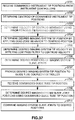
- Figures 17-19 are diagrammatic plan views that illustrate aspects of preventing undesired instrument collision with tissue.
- Instruments may collide with patient tissue outside of an imaging system's field of view in spaces confined by patient anatomy (e.g., laryngeal surgery). Such collisions may damage tissue.
- some DOFs may be inside the field of view while other, more proximal DOFs may be outside the field of view. Consequently, a surgeon may be unaware that tissue damage is occurring as these proximal DOFs move.
- an endoscopic imaging system 2920 extends from the end of guide tube 2922.
- the left side working instrument 2924a is placed so that all DOFs are within imaging system 2920's field of view 2926 (bounded by the dashed lines).
- the right side working instrument 2924b has proximal DOFs (an illustrative parallel motion mechanism as described above and wrist are shown) that are outside field of view 2926, even though instrument 2924b's end effector is within field of view 2926.
- This instrument position is illustrative of tasks such as tying sutures.
- field of view boundaries can be determined when the camera is manufactured so that the boundaries are known in relation to the camera head (image capture component).
- the boundary information is then stored in a nonvolatile memory associated with the imaging system that incorporates the camera head. Consequently, the control system can use the imaging system instrument's kinematic and joint position information to locate the camera head relative to the working instruments, and therefore the control system can determine the field of view boundaries relative to the working instruments. Instruments are then controlled to work within the boundaries.
- field of view boundaries can be determined relative to the instruments by using machine vision algorithms to identify the instruments and their positions in the field of view.
- This "tool tracking" subject is disclosed in U.S. Patent Application Publication No. US 2006/0258938 A1 (Hoffman et al. ), which is incorporated by reference.
- imaging system 2920 is placed so that the camera head is just at the distal end of guide tube 2922.
- Instruments 2924a and 2924b are extended from the distal end of the guide tube and within imaging system 2920's field of view.
- An "Allowable Volume” is defined to be coincident with the field of view boundaries.
- the control system prevents any part of instruments 2924a and 2924b from moving outside the Allowable Volume. Since the surgeon can see all distal moving parts of instruments 2924a and 2924b, the surgeon then moves the instruments without colliding with surrounding tissue. The instrument movements are recorded, and an "Instrument Volume" 2928 (bounded by the dotted lines), which is bounded by the farthest movements of the instruments, is determined.
- the Instrument Volume is a convex volume within which instruments may be moved without colliding with tissue.
- imaging system 2920 is inserted as shown in Figure 19 .
- field of view 2926 is also inserted, and parts of instruments 2924a,2924b are outside of the inserted field of view 2926.
- a new Allowable Volume is determined to be the newly inserted field of view plus the previously determined Instrument Volume that is outside of the field of view. Therefore, the control system will allow the surgeon to move an instrument anywhere within the new Allowable Volume. The process may be repeated for further field of view insertions or for guide tube 2922 movements.
- This scheme allows a surgeon to define the allowable instrument range of motion in real time without requiring a tissue model. The surgeon is only required to trace the boundaries of the instrument range of motion inside the field of view, and the control system will record this information as the field of view is changed.
- Figure 20 is a diagrammatic view of a display (e.g., stereoscopic) that a surgeon sees during a surgical procedure.
- a display e.g., stereoscopic
- the image from the new, more inserted field of view 2940 (bounded by the dashed lines) is registered and mosaiced with the image from the old, more withdrawn field of view 2942.
- Image mosaicing is known (see e.g., U.S. Patents No. 4,673,988 (Jansson et al. ) and 5,999,662 (Burt et al. ), which arc incorporated by reference) and has been applied to medical equipment (see e.g., U.S. Patent No.
- Figure 21 is a diagrammatic perspective view that shows aspects of an illustrative minimally invasive surgical instrument assembly that includes a multi-jointed instrument dedicated to retraction.
- guide tube 3102 includes a channel 3104, through which an imaging system is inserted, and three channels 3106a,3106b,3106c, through which surgical instruments may be inserted.
- Retraction instrument 3108 is shown extending through channel 3106c.
- retraction instrument 3108 includes a proximal instrument body 3110 and four serial links 3112a-d.
- joints 3114a-d couple proximal instrument body 3110 and links 3112a-d together.
- each joint 3114a-d is an independently controllable single DOF pitch joint. In other aspects the joints may have additional DOFs.
- An actively controlled (either hand or telemanipulated) gripper 3116 is mounted at the distal end of the most distal link 3112d via a passive roll joint 3118. In some aspects other end effectors, or none, may be substituted for the gripper.
- the combined length of links 3112a-d and gripper 3116 is sufficient to retract tissue beyond the working envelope of instruments that extend through channels 3106a and 3106b.
- the combined lengths of the links and the gripper may be approximately equal to the full insertion range (e.g., approximately 5 inches) of the instruments.
- Four links and joints are shown, and other numbers of links and joints may be used. Retraction is done using various combinations of pitching joints 3114a-d and rolling instrument 3108 within channel 3106c.
- instrument 3108 is inserted so that each joint 3114a-d is exposed one after the other. Insertion depth may be varied so that retraction can begin at various distances from the distal end of the guide tube with various numbers of joints as the joints exit from the guide tube's distal end. That is, for example, retraction may begin as soon as joint 3114d is inserted past the distal end of the guide tube.
- gripper 3116 may grip tissue. Passive roll joint 3118 prevents the gripped tissue from being torqued as instrument 3108 is rolled within channel 3106c.
- the control system couples the motions of instrument 3108 and guide tube 3102.
- This coupled control of motion allows tissue to be held in place by gripper 3116 as the guide tube is moved to the left or right "underneath" the retracted tissue.
- instrument 3108 is rolled (and joint 3114a-d pitch may be changed) to move gripper 3116 to the right.
- Figure 21 further illustrates an aspect of instrument position and control within guide tubes.
- the working surgical instruments need not be inserted though guide tube channels that correspond to or are aligned with their working position.
- the left side working instrument does not have to be inserted through the left-most channel 3106c. Instead, the left side working instrument may be inserted via the "bottom" channel 3106b. The right side working instrument may then be inserted via the right-most channel 3106a. Then, the left and right side working instruments may be controlled to work at a surgical site in alignment with the field of view of an imaging system inserted via channel 3104 that has not been rolled or yawed.
- left-right axis between the working instruments' insertion channels does not have to be aligned with the left-right axis between the working instruments' end effectors at the surgical site or with the left-right axis interpupillary axis of the stereoscopic imaging system.
- left-right instrument position may be varied.
- retraction instrument 3108 may be inserted via channel 3106a
- the right side working instrument may be inserted via channel 3106b
- the left side working instrument may be inserted via channel 3106c.
- the imaging system may be inserted via one of several channels.
- top channel 3104 and “bottom” channel 3106b may be oblong shaped with a center bore that holds a cylindrical instrument body. Consequently, an imaging system may be inserted via the “top” or “bottom” channel, and a working instrument may be inserted via the other "top” or “bottom” channel.
- Figure 22 is a block diagram of components used for controlling and selectively associating medical devices on the patient side support system 2104 to operator manipulated input devices 203, 204 of the surgeon's console 2102.
- Various surgical tools such as graspers, cutters, and needles may be used to perform a medical procedure at a work site within the Patient.
- three surgical tools (TOOL1,TOOL2,TOOL3) 2231,2241,2251 are used to robotically perform the procedure and the imaging system (IS) 2261 is used to view the procedure.
- the tools 2231,2241,2251 and imaging system 2261 may be disposed in a guide tube (GT) 2271 so as to be extendable beyond a distal end of the guide tube 2271.
- GT guide tube
- the guide tube 2271 may be inserted into the Patient through an entry aperture such as a minimally invasive incision or a natural orifice using the setup portion of a robotic arm assembly and maneuvered by a guide tube manipulator 2272 towards the work site where the medical procedure is to be performed.
- an entry aperture such as a minimally invasive incision or a natural orifice using the setup portion of a robotic arm assembly and maneuvered by a guide tube manipulator 2272 towards the work site where the medical procedure is to be performed.
- Each of the devices 2231,2241,2251,2261,2271 is manipulated by its own manipulator.
- the imaging system 2261 is manipulated by an imaging system manipulator (PSM4) 2262
- the first surgical tool 2231 is manipulated by a first tool manipulator (PSM1) 2232
- the second surgical tool 2241 is manipulated by a second tool manipulator (PSM2) 2242
- the third surgical tool 2251 is manipulated by a third tool manipulator (PSM3) 2252
- the guide tube 2271 is manipulated by a guide tube manipulator 2272.
- Each of the instrument manipulators 2232,2242,2252,2262 is a mechanical assembly that carries actuators and provides a mechanical, sterile interface to transmit motion to its respective articulated instrument.
- Each instrument 2231,2241,2251,2261 is a mechanical assembly that receives the motion from its manipulator and, by means of a cable transmission, propagates the motion to its distal articulations (e.g., joints). Such joints may be prismatic (e.g., linear motion) or rotational (e.g., they pivot about a mechanical axis).
- the instrument may have internal mechanical constraints (e.g., cables, gearing, cams, belts, etc.) that force multiple joints to move together in a pre-determined fashion.
- Each set of mechanically constrained joints implements a specific axis of motion, and constraints may be devised to pair rotational joints (e.g., joggle joints). Note also that in this way the instrument may have more joints than the available actuators.
- each of the input devices 203,204 may be selectively associated with one of the devices 2261,2231,2241,2251, 2271 through a multiplexer (MUX) 2290 so that the associated device may be controlled by the input device through its controller and manipulator.
- MUX multiplexer
- the Surgeon may specify the association through a graphical user interface (GUI) 2291 on the surgeon's console 2102 for the left and right input devices 203,204 to be respectively associated with the first and second surgical tools 2231, 2241, which are telerobotically controlled through their respective controllers 2233, 2243 and manipulators 2232,2242 so that the Surgeon may perform a medical procedure on the Patient while the surgical tool 2251, imaging system 2261 and guide tube 2271 are each soft locked in place through their respective controllers (such as shown in Figures 24, 25 ).
- GUI graphical user interface
- the Surgeon may do so by simply disassociating the input device from its currently associated device and associating it instead to the tool 2251.
- the Surgeon may do so by simply disassociating the input device from its currently associated device and associating it instead to the imaging system 2261 or guide tube 2271.
- the selective association of the input devices 203,204 to devices 2251,2241,2231,2261,2271 may be performed by the Surgeon using voice commands understood by a voice recognition system, or by the Surgeon depressing a button on one of the input devices 203,204, or by the Surgeon depressing a foot pedal on the surgeon's console 2102, or by the Surgeon using any other well known mode switching technique. Although such mode switching is described herein as being performed by the Surgeon, it may alternatively be performed by an Assistant under the direction of the Surgeon.
- FIG. 23 illustrates, as an example, a block diagram of a master/slave control system 300 for controlling movement of the tool slave manipulator 2232 when it is associatecd with the input device 203 and consequently, the position and orientation of its attached tool 2231, as commanded by movement of the master manipulator 203 by the Surgeon.
- a similar master/slave control system may be provided for each of the other slave manipulators (e.g., 2241,2251,2261,2271) in the system 2100.
- Both the master and slave manipulators include a number of linkages connected by joints so as to facilitate multiple degrees-of-freedom movement.
- sensors associated with the master manipulator joints provide information indicating such command movement in master joint space
- sensors associated with the slave manipulator joints provide information indicating slave manipulator and consequently, tool 2231 movement in slave joint space for feedback purposes.
- a master input processing unit 301 receives the information of the master joint positions, which are sampled at the control system processing rate (e.g., 1300 Hz in the present example), from the master joint sensors in the master manipulator 203, and computes joint velocities from the sensed joint positions.
- the control system processing rate e.g. 1300 Hz in the present example
- a master forward kinematics processing unit 302 receives the master joint positions and velocities from the master input processing unit 301, transforms them from master joint space to corresponding positions and velocities of the master frame (i.e., the frame associated with the master manipulator 203) in Cartesian space relative to the eye reference frame (i.e., the reference frame associated with the position of the surgeon's eyes), using, for example, a Jacobian matrix and eye related information separately determined and provided in block 303.
- a scale and offset processing unit 304 receives the Cartesian position and velocity commands from the master forward kinematics processing unit 302, scales the commanded movement according to a scale factor selected to perform the surgical procedure, and takes into account offsets to generate desired slave tool frame (i.e., the frame associated with the tool 2231) positions and velocities.
- desired slave tool frame i.e., the frame associated with the tool 2231
- Cartesian position is to be interpreted to include Cartesian orientation in this specification where appropriate
- Cartesian velocity is to be interpreted to include translational and angular velocities where appropriate.
- the scale adjustment is useful where small movements of the slave manipulator 2232 are desired relative to larger movement of the master manipulator 203 in order to allow more precise movement of the slave tool 2231 at the surgical site.
- the offsets determine, for example, the corresponding position and/or orientation of an end effector frame (e.g., the frame associated with an end effector of the tool 2231) in the camera reference frame (i.e., the frame associated with the image capturing end of the imaging system) relative to a position and orientation of the master frame in the eye reference frame.
- an end effector frame e.g., the frame associated with an end effector of the tool 2231
- the camera reference frame i.e., the frame associated with the image capturing end of the imaging system
- a simulated slave processing unit 308 receives desired slave tool frame position and velocity commands from the scale and offset processing unit 304, and limits the desired slave tool frame position, orientation and velocities, to assigned Cartesian limits for instance to enforce correct and intuitive operation of the tool 2231 by keeping it within its dexterous workspace and to prevent motions that would result in excessive forces being exerted by the end effector of the tool 2231.
- the simulated slave processing unit 308 generates simulated slave joint positions and velocities corresponding to the limited slave tool frame positions and velocities, while making sure that the generated slave joint positions and velocities do not exceed the actual slave joint's range of motion and maximum velocities (i.e., joint limits) even in the vicinity of kinematic singularities for the slave kinematics.
- An inverse scale and offset processing unit 306 receives the simulated joint position and velocity commands from the simulated slave processing unit 308, and performs an inverse function to that of the scale and offset processing unit 304 on them.
- a Cartesian controller 307 receives as first inputs, the inputs to the scale and offset processing unit 304 and as second inputs, the outputs of the inverse scale and offset processing unit 306.
- a master transpose kinematics processing unit 315 receives the Cartesian force F CART through a summation node 314, and generates a corresponding torque in joint space using, for example, the Jacobian transpose matrix and kinematic relationships associated with the master manipulator 203.
- a master output processing unit 316 receives the master torque signals from the master transpose kinematics processing unit 315, generates electrical currents corresponding to the master torque signals, and supplies the electrical currents to corresponding master joint motors of the master manipulator 203.
- a surgeon operating the master manipulator 203 feels the Cartesian force, F CART , whenever the surgeon is commanding a position or velocity which exceeds system Cartesian or slave joint limits, or would result in a kinematic singularity condition for the slave manipulator 2232.
- a slave input processing unit 309 is also receiving slave joint positions from position sensors in the slave manipulator 2232 at the control system processing rate.
- a joint control unit 320 receives the slave joint positions from the slave input processing unit 309 and the simulated joint position commands provided from the simulated slave processing unit 308, and generates slave torque command signals for the slave joint motors and master torque feedback command signals for the master joint motors.
- the slave torque command signals are generated by the joint control unit 320 so as to drive joints of the slave manipulator until feedback errors calculated in the joint control unit 320 zero out.
- a slave output processing unit 310 receives the slave torque command signals from the joint control unit 320, converts them into appropriate electrical currents, and supplies the electrical currents to the joint motors of the slave manipulator so as to drive the motors accordingly.
- the master torque feedback command signals are generated by the joint control unit 320 as a function of the slave joint position and velocity tracking errors so as to reflect forces being exerted against the tool 2231 or its slave manipulator 2232 back to the master manipulator 203 so that they may be felt by the Surgeon.
- a kinematic mapping unit 311 receives the master torque feedback command signals from the joint control unit 320, and generates the corresponding Cartesian force being exerted against the tip of the tool 2231 relative to the camera frame of the imaging system using the slave kinematic configuration and the previously calculated slave reference frame position information provided in block 312.
- a gain 313 adjusts the magnitude of the Cartesian force so as to ensure system stability while providing adequate force sensation to the Surgeon.
- the gain adjusted Cartesian force is then passed through the summation node 314, and processed along with the Cartesian force provided by the Cartesian controller 307 through the master transpose kinematics processing unit 315 and master output processing 316 as previously described in reference to their processing of the Cartesian force provided by the Cartesian controller 307.
- the joint control unit 320 includes a joint controller for each active joint and gear of the slave manipulator 2232 that is being controlled by the master/slave control system 300.
- each of these joints will have its own controller.
- joint is to be understood as a connection (translational or revolute) between two links, and may include gears (or prismatic joints) as well as any other controllable component coupled to linear drive mechanisms that may be used in controlling robotic arm assemblies.
- Direct control modes are control modes in which the user has direct control over a specific slave manipulator. All other slave manipulators (i.e., the ones that are not connected to a master device) are soft-locked (i.e., all their joints are held in place by their respective controllers).
- three direct control modes are defined as a direct "tool following" mode in which the two hand-operable input devices are associated with two tool slave manipulators and their respective tools, a direct "imaging system” mode in which one or both of the hand-operable input devices are associated with the imaging system, and a direct “guide tube” mode in which one or both hand-operable input devices are associated with the guide tube.
- Figures 24-25 illustrate a direct "tool following" mode in which the left and right master input devices 204,203 are respectively associated with the first and second tools while a third tool, the imaging system and the guide tube are held in place by their respective controllers;
- Figures 26-27 illustrate a direct "imaging system” mode in which the left master input device 204 is associated with the imaging system while the first tool, second tool, third tool and guide tube are held in place by their respective controllers;
- Figures 28-29 illustrate a direct "guide tube” mode in which the left and right master input devices 204,203 are associated with the guide tube while the first tool, second tool, third tool and imaging system are held in place by their respective controllers.
- data pick-off/receiving points are available to provide commanded state information to non-associated controllers for coupled control modes and receive state information back from the non-associated controllers, as described herein.
- both the inverse scale & offset block 306 and scale & offset block 304 are included in a single block designated as "Scale & Offset" in the figures.
- the master/slave control system 300 has been split into master and slave side portions (on opposite sides of the "Scale & Offset" blocks) with the PSM1* Controller 248, PSM2* Controller 247, PSM4* Controller 268, and GT* Controller 288 comprising the slave side components (e.g., control system 300 blocks 308,320,309,310,311,312,313 of Figure 23 ) and the MTM Controllers 241,242,262,281,282 comprising the master side components (e.g., control system 300 blocks 301,302,303,307,314,315,316 of Figure 23 ).
- the PSM1* Controller 248, PSM2* Controller 247, PSM4* Controller 268, and GT* Controller 288 comprising the slave side components (e.g., control system 300 blocks 308,320,309,310,311,312,313 of Figure 23 ) and the MTM Controllers 241,242,262,281,282 comprising the master side components (e.g., control system 300 blocks 301,
- Hold position blocks 251,252,253,271,272 in Figures 25 , 27 , 29 indicate state commands (each indicating a constant position and orientation for its respective device) that are stored in one or more memory devices and respectively provided to the slave side PSM3* Controller 258, GT* Controller 288, PSM4* Controller 268, PSM1* Controller 248, and PSM2* Controller 247, while following data generated in these controllers are ignored (or otherwise discarded) as indicated by downward point arrows from these controllers, so that their respective manipulators and devices are held at the commanded states.
- a coupled control mode the Surgeon is directly controlling movement of an associated slave manipulator (e.g., one of the manipulators 2232,2242,2252,2262,2272) while indirectly controlling movement of one or more non-associated slave manipulators, in response to commanded motion of the directly controlled slave manipulator, to achieve a secondary objective.
- secondary objective include optimizing device workspaces (i.e., maximizing their ranges of motion), optimizing the imaging system's view of other devices and/or the work site, minimizing the chance of collisions between devices and/or the patient's anatomy, and driving non-associated devices to desired poses.
- coupled control modes allow the Surgeon to better focus on performing the medical procedure and to pay less attention to managing the system.
- the user interface has three coupled control modes: a mode for the instrument(s), a mode for the imaging system, and a mode for guide tube (i.e. as many modes as the number of manipulators designed to perform different functions within the surgical system).
- haptic cues it is useful to provide haptic cues to the Surgeon to indicate when motion of a coupled manipulator occurs, since the Surgeon otherwise may not be aware of the movement of any device that is being indirectly controlled through a coupled control mode. This is not a problem for directly controlled devices, because the master/slave control system for such directly controlled devices generally provides a haptic feedback path. Therefore, a haptic cue such as a detent may be provided that signals to the Surgeon when a coupled mode becomes engaged.
- the GUI 2291 used by the Surgeon to specify the association of inputs devices 203,204 and devices 2231,2241,2251,2261,2271 may also be used by the Surgeon to specify various parameters of the coupled control modes. For example, the Surgeon may use the GUI 2291 to select which device manipulators participate in various coupled control modes and to define and/or prioritize the secondary objectives associated with the coupled control modes.
- Figure 30 is a diagrammatic view that illustrates coupled control aspects of a centralized motion control and coordination system architecture for minimally invasive telesurgical systems that incorporate surgical instrument assemblies and components described herein.
- a motion coordinator system 2202 receives master inputs 2204, sensor inputs 2206, and optimization inputs 2208.
- Master inputs 2204 may include the surgeon's arm, wrist, hand, and finger movements on the master control mechanisms. Inputs may also be from other movements (e.g., finger, foot, knee, etc. pressing or moving buttons, levers, switches, etc.) and commands (e.g., voice) that control the position and orientation of a particular component or that control a task-specific operation (e.g., energizing an electrocautery end effector or laser, imaging system operation, and the like).
- movements e.g., finger, foot, knee, etc. pressing or moving buttons, levers, switches, etc.
- commands e.g., voice
- a task-specific operation e.g., energizing an electrocautery end effector or laser, imaging system operation, and the like.
- Sensor inputs 2206 may include position information from, e.g., measured servomotor position or sensed bend information.
- U.S. Patent Application No. 11/491,384 entitled "Robotic surgery system including position sensors using fiber Bragg gratings", incorporated by reference, describes the use of fiber Bragg gratings for position sensing.
- Such bend sensors may be incorporated into the various instruments and imaging systems described herein to be used when determining position and orientation information for a component (e.g., an end effector tip).
- Position and orientation information may also be generated by one or more sensors (e.g., fluoroscopy, MRI, ultrasound, and the like) positioned outside of the patient, and which in real time sense changes in position and orientation of components inside the patient.
- Optimization inputs 2208 relate to the secondary objectives. They may be high-level commands, or the inputs may include more detailed commands or sensory information.
- An example of a high level command would be a command to an intelligent controller to optimize a workspace.
- An example of a more detailed command would be for an imaging system to start or stop optimizing its camera.
- An example of a sensor input would be a signal that a workspace limit had been reached.
- Motion coordinator 2202 outputs command signals to various actuator controllers and actuators (e.g., servomotors) associated with manipulators for the various telesurgical system arms.
- Figure 30 depicts an example of output signals being sent to two instrument controllers 2210, to an imaging system controller 2212, and to a guide tube controller 2214. Other numbers and combinations of controllers may be used.
- the motion coordinator 2202 determines how to take advantage of the overall system kinematics (i.e., the total degrees of freedom of the system) to achieve the secondary objectives indicated by the optimization inputs 2208.
- such a motion coordination system may be used to control surgical instrument assembly 1700 ( Figure 6 ).
- Instrument controllers 2210 are associated with instruments 1702a,1702b
- imaging system controller 2212 is associated with imaging system 1704
- guide tube controller 2214 is associated with guide tube 1708.
- surgeon who operates the telesurgical system will simultaneously and automatically access at least the three control modes identified above: an instrument control mode for moving the instruments, an imaging system control mode for moving the imaging system, and a guide tube control mode for moving the guide tube.
- a similar centralized architecture may be adapted to work with the various other mechanism aspects described herein.
- FIG 31 is a diagrammatic view that illustrates aspects of a distributed motion control and coordination system architecture for minimally invasive telesurgical systems that incorporate surgical instrument assemblies and components described herein.
- control and transform processor 2220 exchanges information with two master arm optimizer/controllers 2222a,2222b, with three surgical instrument optimizer/controllers 2224a,2224b,2224c, with an imaging system optimizer/controller 2226, and with a guide tube optimizer/controller 2228.
- Each optimizer/controller is associated with a master or slave arm (which includes, e.g., the camera (imaging system) arm, the guide tube arm, and the instrument arms) in the telesurgical system.
- Each of the optimizer/controllers receives arm-specific optimization goals 2230a-2230g.
- control and transform processor 2220 routes the Following Data received from each optimizer/controller to all the optimizer/controllers so that each optimizer/controller has data about the current Cartesian configuration of all arms in the system.
- the optimizer/controller for each arm receives optimization goals that are unique for the arm.
- Each arm's optimizer/controller then uses the other arm positions as inputs and constraints as it pursues its optimization goals.
- each optimization controller uses an embedded local optimizer to pursue its optimization goals.
- the optimization module for each arm's optimizer/controller can be independently turned on or off. For example, the optimization module for only the imaging system and the guide tube may be turned on.
- the distributed control architecture provides more flexibility than the centralized architecture, although with the potential for decreased performance. It easier to add in a new arm and to change the overall system configuration if such a distributed control architecture is used rather than if a centralized architecture is used. In this distributed architecture, however, the optimization is local versus the global optimization that can be performed with the centralized architecture, in which a single module is aware of the full system's state.
- Figures 32-34 illustrate aspects of particular coupled control modes where associated devices are directly controlled to accomplish primary objectives and non-associated devices are indirectly controlled to accomplish secondary objectives.
- Figure 32 illustrates a coupled "tool following" mode example in which the left and right master input devices 204,203 are respectively associated with the first and second tools while information of their commanded movement is made available by coupling blocks 3202,3201 connected to data pick-off points of their respective master/slave control systems to coupled controllers 3204,3203 of the imaging system and the guide tube so that they may perform desired "secondary” objectives;
- Figure 33 illustrates a coupled "imaging system” mode example in which the left master input device 204 is associated with the imaging system while information of its commanded movement is made available by a coupling block 3302 connected to data pick-off points of its master/slave control system to coupled controllers 3304,3305,3303 of the first tool, second tool, and guide tube so that they may perform desired "secondary” objectives;
- Figure 34 illustrates a coupled "guide tube” mode example in which the left and
- coupling blocks and device coupled controllers illustrated in Figures 32-34 may be implemented in a distributed fashion as shown so that they are either integrated in or implemented outside their respective controllers or they may be implemented in a centralized fashion so they are integrated into a single unit outside of their respective controllers.
- coupling blocks 3201,3202 are coupled to the data pick-off/receiving points (as shown in Figure 24 ).
- Device coupled controllers 3203,3204 which command and control their respective device controllers to perform secondary objectives, are coupled at data pick-off/receiving points of their respective device controllers and to the coupling blocks 3202,3201 so that they may receive and send information back and forth as indicated by the arrows in Figure 32 .
- coupling block 3302 (as shown in Figure 33 ) is coupled to the data pick-off/receiving points (as shown in Figure 26 ).
- Device coupled controllers 3303,3304,3305 which command and control their respective device controllers to perform secondary objectives, are coupled at data pick-off/receiving points of their respective device controllers and to the coupling block 3302 so that they may receive and send information back and forth as indicated by the arrows in Figure 33 .
- coupling block 3402 (as shown in Figure 34 ) is coupled to the data pick-off/receiving points (as shown in Figure 28 ).
- Device coupled controllers 3403,3404,3405 which command and control their respective device controllers to perform secondary objectives, are coupled at data pick-off/receiving points of their respective device controllers and to the coupling block 3402 so that they may receive and send information back and forth as indicated by the arrows in Figure 34 .
- Figures 35-40 are flow diagrams illustrating examples of coupled control modes.
- the user interface has three coupled control modes: a mode for the instrument(s), a mode for the imaging system, and a mode for the guide tube.
- Figures 35-37 and 39 arc examples of instrument coupled control
- Figure 38 is an example of a guide tube coupled control
- Figure 40 is an example of an imaging system coupled control.
- the methods described in reference to Figures 35-40 , as well as various controllers and other processing units described herein are preferably implemented in processor 220 as described in reference to figure 4 .
- Figures 35-36 illustrate a first part of an example of instrument coupled control in which the workspaces of articulated devices that are coupled to a guide tube and extendable beyond a distal end of the guide tube are optimized.
- Figure 6 is one example of such an instrument assembly.
- the present example describes use of a guide tube for optimizing workspaces of articulated devices used to perform a medical procedure, it is to be appreciated that aspects of the invention are also applicable to any base coupled to the articulated devices so that the articulated devices move when the base moves.
- the patient side support system 2104 which is described in reference to Figures 1-3 , may also function as such a base if rotational setup joints 2114a, 2114b are actively drivable.
- the guide tube coupled controller 3203 e.g., the motion coordinator 2202 or the guide tube optimizer/controller 2228, depending upon whether a centralized or distributed coupled mode architecture is employed
- the guide tube coupled controller 3203 that is operating at the time in an instrument coupled control mode, receives commanded device tip positions from coupling blocks and coupled controllers of all devices that are coupled to the guide tube (i.e., devices that move when the guide tube moves).
- a device may be coupled to the guide tube if it is disposed within the guide tube or if it is otherwise physically attached to the guide tube.
- the phrase "device tip position” means information indicative of the Cartesian coordinates in a fixed reference frame for the device's most distal joint and an orientation determined by an angular position of the most distal joint.
- the guide tube coupled controller 3203 uses the received commanded device tip positions to determine a guide tube tip position that optimizes workspaces of the devices coupled to the guide tube while their respective controllers maintain their device tip positions. Since the optimization function requires knowledge of the range of motion limits and kinematics of the devices, as well as the current tip positions of the guide tube and the devices, such range of motion and kinematics information is preferably provided to the guide tube coupled controller 3203 either at system startup or other convenient time in a conventional manner while current tip positions of the devices are provided during operation by the device coupling blocks and coupled controllers as previously described.
- each of the device controllers may provide a desired Cartesian pose for its device so that the guide tube coupled controller solves the kinematics in such a way as to have the guide tube tip positioned so as to allow the device's joints to be configurable as close as possible to its desired pose while not moving its tip from the desired tip position.
- weight values may be selected so that maximizing the ranges of motions of the instruments 2231,2241 being directly controlled is more heavily weighted (i.e., having higher priority) than maximizing the range of motion of the imaging system 2261 and any other device whose tip is being held in place (i.e., held or "soft-locked" in position by its controller).
- the determined guide tube tip position is then provided to the guide tube controller 2272 to drive the guide tube 2271 to the determined tip position and to the device controllers 2233,2243,2263 so that they may drive their respective devices 2231,2241,2261 to articulated joint configurations that optimize their respective workspaces as described in reference to Figure 36 as follows.
- the commanded position of the guide tube 2271 is received from the guide tube coupled controller.
- the device controllers generate updated joint position commands for their respective slave manipulators to accommodate the new guide tube position while satisfying commanded device tip positions.
- the commanded device tip positions correspond to tip positions commanded by the input devices 204,203.
- the commanded device tip positions are their current tip positions so that the tips of these non-associated devices are effectively held in place.
- the device controllers provide the updated joint position commands to their respective slave manipulators so that the device workspaces are optimized.
- Figure 37 illustrates an optional second part of the example in which movement of the imaging system 2261 is coupled to movement of the instruments 2231,2241 so that the instruments are well placed in a field of view of the imaging system.
- the first part of the example described in reference to Figures 35-36 addresses the secondary objective of optimizing the workspaces of devices coupled to the guide tube and extendable beyond the distal end of the guide tube
- the second part of the example addresses the secondary objective of optimizing the view of the device tips in images captured by the imaging system.
- the imaging system coupled controller 3204 e.g., the motion coordinator 2202 or the imaging system optimizer/controller 2226, depending upon whether a centralized or distributed coupled mode architecture is employed
- the imaging system coupled controller determines a centroid of the commanded instrument tip positions and in 3703, it determines a centroid velocity using differences in centroid positions determined in the present and previous digital process periods.
- tremor filtering is performed to determine a desired imaging system tip position and velocity by respectively applying a dead zone behavior to the centroid position and a low pass filter to the centroid velocity.
- the imaging system coupled controller 3204 determines desired joint positions for the imaging system 2261 using inverse kinematics of the articulated imaging system 2261 and the current tip position of the guide tube 2271.
- the imaging system coupled controller determines an imaging system tip position corresponding to the modified slave joint positions using forward kinematics of the imaging system 2261 and provides the determined imaging system tip position to the guide tube coupled controller 3203. Note that the imaging system tip position determined in 3707 should be the same as the desired imaging system tip position in 3704 unless joint limits or singularities were encountered in 3707, in which case, they would be different in order to avoid the limits or singularities.
- the guide tube coupled controller then processes the imaging system tip position along with the instrument tip positions according to the first part of the example as described in reference to Figure 35 to generate a guide tube tip position that optimizes workspaces of the instruments and imaging system.
- the imaging system coupled controller 3204 receives the commanded guide tube tip position from the guide tube coupled controller 3203 and uses it in 3709 to determine commanded slave joint positions by applying the imaging system tip position determined in 3707 and the modified guide tube tip position to the same equations and limits used in performing 3706.
- the commanded slave joint positions determined by the imaging system controller 2263 are then provided as actuator commands to the imaging system manipulator 2262 to manipulate or move the imaging system 2261 accordingly.
- the retraction instrument 3108 depicted in Figure 21 can only be fully retracted into channel 3106c of guide tube 3102 after each of its links 3112a-3112d is aligned with the channel 3106c.
- Figure 38 illustrates an example of using coupled control for retracting medical devices into a guide tube.
- the example employs a virtual degree of freedom (DOF) of the guide tube manipulator for controlling the retraction. Since all devices are coupled to the guide tube, all devices move as the guide tube moves.
- the guide tube manipulator in this example doesn't have an actuator for insertion/retraction, so it effects a virtual insertion/retraction DOF by causing the devices to be moved in the desired insertion/retraction direction by passing the guide tube insertion/retraction command to each of the device controllers while the guide tube remains in place.
- the guide tube coupling block 3402 periodically receives conventional time-sampled output from its associated Surgeon manipulated input device(s) that indicates in this case that the guide tube is to be retracted backward (e.g., away from a work site) along its longitudinal axis.
- the coupling block 3402 relays the received retraction commands to the other device coupled controllers so that they in turn, command their respective device manipulators to retract their respective devices in the desired retraction direction from their positions at the time.
- each of the device controllers determines when the proximal end of the most proximal rotated link of its respective device is within a threshold distance "TH" from the distal end of the guide tube.
- the threshold distance "TH” may be determined, for example, by taking into account the current rotation angle of the most proximal rotated link, the rate at which the retraction is being commanded by the Surgeon on the input device, and the clearance between the "straightened out” device and the channel through which the device extends through in the guide tube.
- the threshold distance "TH” is selected so that each of the devices may be retracted back into the guide tube without striking the ends or sides of its respective channel through which it is disposed.
- the distance between the proximal end of the most proximal rotated link of device and the distal end of the guide tube may be determined in a conventional manner by determining a first vector that extends from a remote center "RC" (i.e., a pivot point of the guide tube) to the distal end of the guide tube, determining the most proximal rotated link of the device, determining a second vector that extends from the remote center "RC" to the most proximal joint rotating the most proximal rotated link of the device, and determining the distance between the proximal end of the most proximal rotated link of a device and the distal end of the guide tube from the difference between the first and second vectors.
- RC remote center
- each of the device controllers drives its device to a retraction configuration (i.e., a joint and link configuration that allows the device to be fully retracted into the guide tube) upon determining that the proximal end of the most proximal rotated link of its respective device is within the threshold distance "TH" from the distal end of the guide tube.
- the rate that the device is driven to its retraction configuration is determined at least in part by the rate at which the output of the input device is changing in the insertion/retraction commanded direction so that collisions between the device and the guide tube are avoided.
- each of the device controllers drives its device to its retraction configuration.
- the device controller allows its respective device to be retracted into its channel in the guide tube in response to retraction commands issued from the input device(s) associated at the time with the guide tube.
- the most proximal rotated link of the imaging system will generally be the first rotated link of the group of devices extending beyond the distal end of the guide tube to reach the threshold distance "TH" from the distal end when the group of devices is being retracted.
- its device controller drives its device to its retraction configuration.
- each of the device controllers may start driving its device to the retraction configuration immediately upon receiving a command indicating desired movement in the retraction direction.
- each device controller is configured to drive its device to its retraction configuration in a manner that ensures that any rotated link of the device is properly aligned to freely enter the device's channel prior to its entry into the channel while avoiding harm to the patient and collisions with other devices.
- the imaging system controller uses the received information of the position of the associated instrument's end effector to command movement of its image capturing end to maintain the end effector in its field of view. Since the operator is viewing the image captured by the image capturing end on a display screen while moving the input device, the operator may become disoriented and/or move the input device in an incorrect manner to properly command retraction of its associated instrument. To compensate for such a non-intuitive experience, the reference frames (i.e.
- blocks 303 and 312 of Figure 23 used to compute kinematics of the master and slave manipulators (i.e., blocks 302 and 311 of Figure 23 ) are modified such that the position/orientation of the master with respect to the display screen being viewed by the operator constantly corresponds to the position and orientation of the tip (e.g., point on the end effector) of the associated instrument with respect to the tip (e.g., point on the image capturing end) of the imaging system.
- the tip e.g., point on the end effector
- a device controller may automatically drive the device to a desired operational configuration.
- the desired operational configuration may be a preferred configuration stored in a memory device associated with one or more processors that implement the various controllers and processes described herein. Alternatively, it may be a previously assumed operational configuration that has been stored the memory device.
- the device joint positions for the operational configurations of the devices just prior to initiating their retraction towards the guide tube may be stored in the memory device so that if the Surgeon decides to re-insert the devices (or their replacement devices after a tool exchange procedure), their device controllers may automatically drive the devices back to the stored operational configurations.
- a surgical instrument is removable and may be replaced with a different surgical instrument that has a structure similar to instrument but a different end effector so as to perform a different surgical task. Accordingly, a single guide tube may be used for one or more interchangeable surgical instruments. In one instance the end effector of the surgical instrument is removable so that it may be readily exchanged with another. In another instance, a surgical accessory such as a clip or suturing material may be provided to a grasping end effector for delivery to the work site while guide tube remains in the patient.
- a convenient way of performing such end effector exchange (also referred to herein as a "tool exchange") or providing such a surgical accessory to a retracted grasping end effector is to use a fenestrated guide tube wherein one or more cut-outs are provided in the guide tube in a part externally extending out of the patient while another part of the guide tube extends internally into the patient through the entry aperture.
- Figure 39 illustrates an example of using coupled control for retracting medical devices into a fenestrated guide tube for a tool exchange or other purpose such as delivering a surgical accessory to the work site.
- a plurality of devices including an imaging system and at least two instruments extend through and beyond the distal end of a guide tube.
- a retraction command is received from an input device associated with an instrument to be retracted (referred to herein as the "associated instrument").
- the retraction command is indicated by movement of the input device in a direction that would result in commanding the associated instrument to be retracted back towards and/or into a distal end of the guide tube.
- sensed joint movement of the input device is processed by the instrument's master/slave control system and the resulting commanded state of the distal tip of the associated instrument is picked off at the output of the scale & offset block and provided along with information identifying the associated instrument (and in particular, its placement in the guide tube) through a coupling block to coupled controller blocks of other devices in the system.
- coupled controller blocks making affirmative determinations then relay the received retraction commands to their respective controllers, which in turn, command their respective device manipulators to retract their devices (referred to herein as the "coupled devices") in the desired retraction direction from their positions at the time.
- each of the retracting device controllers determines when the proximal end of the most proximal rotated link of its respective device is within a threshold distance "TH" from the distal end of the guide tube in the manner described in reference to 3803 of figure 38 .
- each of the device controllers then commands its respective device manipulator to drive its device to a retraction configuration (i.e., a joint and link configuration that allows the device to be fully retracted into the guide tube) upon determining that the proximal end of the most proximal rotated link of its respective device is within the threshold distance "TH" from the distal end of the guide tube in the manner described in reference to 3804 of figure 38 (including compensating for the moving imaging system as described therein).
- a retraction configuration i.e., a joint and link configuration that allows the device to be fully retracted into the guide tube
- the device controller allows its respective device to be retracted into its channel in the guide tube in response to retraction commands issued from the input device.
- Figure 40 illustrates an example of using coupled control for extending medical devices out of the guide tube and inserting it towards a work site.
- any one of the devices may be directly controlled while the others are indirectly controlled for insertion towards the work site
- the example assumes the imaging system is being directly controlled for insertion while the instruments are indirectly controlled through coupled control to follow the image capturing end of the imaging system.
- Using the imaging system to lead the insertion is advantageous since it allows the surgeon to see the path towards the work site.
- Control during insertion may be accomplished, for example, in a manner similar to telemanipulated endoscope control in the da Vinci® Surgical System-in one aspect the surgeon virtually moves the image with one or both of the masters; she uses the masters to move the image side to side and to pull it towards herself, consequently commanding the imaging system and its associated instrument assembly (e.g., a flexible guide tube) to steer towards a fixed center point on the output display and to advance inside the patient.
- the camera control is designed to give the impression that the masters are fixed to the image so that the image moves in the same direction that the master handles are moved, as in the da Vinci® surgical system.
- This design causes the masters to be in the correct location to control the instruments when the surgeon exits from camera control, and consequently it avoids the need to clutch (disengage), move, and declutch (engage) the masters back into position prior to beginning or resuming instrument control.
- the master position may be made proportional to the insertion velocity to avoid using a large master workspace.
- the surgeon may clutch and declutch the masters to use a ratcheting action for insertion.
- insertion e.g., past the glottis when entering via the esophagus
- automated insertion e.g., servomotor driven rollers
- image data e.g., MRI, X-ray
- the imaging system controller receives an insertion command from an associated input device.
- the imaging system controller commands the imaging system manipulator to move the imaging system in response to insertion command, while in 4003, the imaging system controller provides the movement command to other device coupled controllers so that they may also command their respective devices to move in response to the imaging system commanded movement.
- the imaging system controller determines whether the image capturing end of the imaging system has reached its desired position. This determination may be performed either automatically based upon programmed criteria or it may be indicated through action taken by the Surgeon such as depressing a button on the input device associated with the imaging system at the time.
- the imaging system controller After the imaging system controller has determined that the image capturing end of the imaging system has reached its desired position it provides an indication of such to the instrument coupled controllers (e.g., the motion controller 2202 or the instrument optimizer/controllers 2224a,2224b,2224c, depending upon which instruments are to be deployed and whether a centralized or distributed coupled mode architecture is employed) so that the instrument controllers in response thereof command their respective instrument manipulators to move their instruments into their optimal operating configurations. Placing the devices in their optimal operating configurations in this case generally involve placing the working ends of the instruments within the field of view of the imaging system and optimizing the workspaces of the instruments (such as shown, for example, in Figure 18 ).
- the instrument coupled controllers e.g., the motion controller 2202 or the instrument optimizer/controllers 2224a,2224b,2224c, depending upon which instruments are to be deployed and whether a centralized or distributed coupled mode architecture is employed
- the image reference frame used by the Surgeon for master/slave teleoperation changes and such change may affect the ability of Surgeon to perform precise surgical motions. In such case, a number of actions may be taken for large motions of the imaging capturing end of the imaging system.
- haptic feedback may be provided on the input device to assist the Surgeon to take appropriate action
- a computer generated auxiliary view of devices extending out of a distal end of a guide tube may be provided from a stable (e.g., fixed) perspective and relied upon by the Surgeon for master/slave teleoperation, or the images captured by the imaging system may be modified in real-time to maintain an intuitively correct master/slave mapping with the modified images displayed on the surgeon console.
Abstract
Description
- This application is a continuation-in-part application of
U.S. Patent Application No. 11/762,200 - This application is also a continuation-in-part application of
U.S. Patent Application No. 12/489,566 U.S. Patent Application No. 12/613,328 U.S. Patent Application No. 12/541,913 - In addition, this application is related to the following United States Patent Applications, all of which are incorporated by reference:
- U.S. Patent Application No.
11/762,217 - U.S. Patent Application No.
11/762,222 - U.S. Patent Application No.
11/762,231 - U.S. Patent Application No.
11/762,236 - U.S. Patent Application No.
11/762,185 - U.S. Patent Application No.
11/762,172 - U.S. Patent Application No.
11/762,165 - U.S. Patent Application No.
11/762,161 - U.S. Patent Application No.
11/762,158 - U.S. Patent Application No.
11/762,154 - U.S. Patent Application No.
11/762,149 - U.S. Patent Application No.
11/762,170 - U.S. Patent Application No.
11/762,143 - U.S. Patent Application No.
11/762,135 - U.S. Patent Application No.
11/762,132 - U.S. Patent Application No.
11/762,127 - U.S. Patent Application No.
11/762,123 - U.S. Patent Application No.
11/762,120 - U.S. Patent Application No.
11/762,118 - U.S. Patent Application No.
11/762,114 - U.S. Patent Application No.
11/762,110 - U.S. Patent Application No.
11/762,204 - U.S. Patent Application No.
11/762,202 - U.S. Patent Application No.
11/762,189 - U.S. Patent Application No.
11/762,191 - U.S. Patent Application No.
11/762,196 - The present invention generally relates to medical robotic systems and in particular, to a medical robotic system providing coupled control modes.
- Minimally invasive surgery is known under various names (e.g., endoscopy, laparoscopy, arthroscopy, endovascular, keyhole, etc.), often specific to the anatomical area in which work is done. Such surgery includes the use of both hand-held and teleoperated/telemanipulated/telepresence (robot assisted/telerobotics) equipment, such as the da Vinci® Surgical System made by Intuitive Surgical, Inc. of Sunnyvale, California. Both diagnostic (e.g., biopsy) and therapeutic procedures ("medical procedures") are done. Instruments may be inserted into a patient percutaneously via surgical incision or via natural orifice. A new, experimental minimally invasive surgery variation is Natural Orifice Transluminal Endoscopic Surgery (NOTES), in which instruments enter via a natural orifice (e.g., mouth, nostril, ear canal, anus, vagina, urethra) and continue to a surgical site via a transluminal incision (e.g., in a gastric or colonic wall) within the body. Although teleoperative surgery using the da Vinci® Surgical System provides great benefits over, for instance, many hand-held procedures, for some patients and for some anatomical areas the da Vinci® Surgical System may be unable to effectively access a surgical site. In addition, further reducing the size and number of incisions generally aids patient recovery and helps reduce patient trauma and discomfort.
- Various slave manipulators are provided in such medical robotic systems to perform useful functions, such as manipulating instruments to perform medical procedures on a patient, positioning and orienting imaging systems such as endoscopic imaging devices to capture images of the instruments' working ends, and delivering the working ends of the instruments and an image capturing end of the imaging system to a work site in the patient. The delivery of the working and image capturing ends of the instruments and imaging system ("medical devices") uses one or more guide tubes and structures that hold and manipulate the guide tube(s). In addition, master manipulators are used as input devices to track the motion of their operator's hands and to provide appropriate haptic feedback to the operator indicative of the state of their associated slave manipulators. Depending on their respective function, the slave and master manipulators ("robotic manipulators") may be designed with different workspaces and dexterities.
- In general, the reachable workspace of a medical device that is being manipulated by a slave manipulator is the set of points and orientations in space that its distal tip (e.g., working or image capturing end) can reach. On the other hand, the dexterous workspace of the medical device's distal tip generally identifies the set of points in space that can be reached by primarily changing its orientation (e.g., changing the position of a wrist joint that orients the distal tip). As explanation, dexterity is a measure of the capability of a robotic manipulator to control the position (in a limited manner) and orientation of the working end of its associated medical device. Further, it relates the joint degrees of freedom (i.e. the number of independently actuated joints in a kinematic chain of the robotic manipulator/medical device) and the Cartesian/output degrees of freedom that describe the independent rigid body positions and orientations of the distal tip. While the number of output (slave manipulator) degrees of freedom (DOF) is often at most six, the number of input (master manipulator) joint DOFs varies greatly depending on the master manipulator design
- As may be readily appreciated, the dexterous workspace is generally a subset of the reachable workspace. To enable the surgeon to finely control working ends of the instruments, instrument slave manipulators are generally designed to optimize their dexterity, even at the expense of sacrificing their overall reachable workspace. To compensate for such limitation, a base manipulator (such as a patient side cart) with a large reachable workspace may be used to deliver the instrument and imaging system slave manipulators near the entry apertures (e.g., minimally invasive incisions or natural orifices) in the patient body. Further, when the instruments and imaging system are disposed within a common guide tube, the guide tube serves as a secondary base since movement of the guide tube in this case effectively moves all of the instruments and the imaging system disposed therein. The instrument and imaging system slave manipulators may then finally deliver the working and image capturing ends of their respective medical devices to the work site (e.g., target anatomy) in the patient.
- The overall capability of a medical robotic system is achieved by a balance between the workspace and dexterity of all the robotic manipulators that constitute it. However, the differences in the individual capabilities of each manipulator have to be clear and well understood by the user in order to effectively utilize the system. It is in general difficult for the user to select which manipulator to control from the console and how to move it in order to achieve a desired "working configuration" of their respective medical devices inside the patient, with the instruments' working ends having the best possible dexterity and reach, while the capturing end of the imaging system is positioned in such a way to provide good visualization of the medical procedure being performed at the work site without interfering with the instruments' movements. Hence, it is desirable to provide the system with the capability of performing secondary or coupled control movements, e.g., for the camera manipulator and the base manipulator (guide tube manipulator and/or manipulator for moving the setup arms and or support for the patient side support system), so as not to distract the user from performing the medical procedure at the time using the surgical instruments.
- The number of degrees of freedom (DOFs) is the number of independent variables that uniquely identify the pose/configuration of a system. Since robotic manipulators are kinematic chains that map the (input) joint space into the (output) Cartesian space, the notion of DOF can be expressed in any of these two spaces. In particular, the set of joint DOFs is the set of joint variables for all the independently controlled joints. Without loss of generality, joints are mechanisms that provide a single translational (prismatic joints) or rotational (revolute joints) DOF. Any mechanism that provides more than one DOF motion is considered, from a kinematic modeling perspective, as two or more separate joints. The set of Cartesian DOFs is usually represented by the three translational (position) variables (e.g., surge, heave, sway) and by the three rotational (orientation) variables (e.g. Euler angles or roll/pitch/yaw angles) that describe the position and orientation of an end effector (or tip) frame with respect to a given reference Cartesian frame.
- For example, a planar mechanism with an end effector mounted on two independent and perpendicular rails has the capability of controlling the x/y position within the area spanned by the two rails (prismatic DOFs). If the end effector can be rotated around an axis perpendicular to the plane of the rails, then there are then three input DOFs (the two rail positions and the yaw angle) that correspond to three output DOFs (the x/y position and the orientation angle of the end effector).
- Although the number of Cartesian DOFs is at most six, a condition in which all the translational and orientational variables arc independently controlled, the number of joint DOFs is generally the result of design choices that involve considerations of the complexity of the mechanism and the task specifications. Accordingly, the number of joint DOFs can be more than, equal to, or less than six. For non-redundant kinematic chains, the number of independently controlled joints is equal to the degree of mobility for the end effector frame. For a certain number of prismatic and revolute joint DOFs, the end effector frame will have an equal number of DOFs (except when in singular configurations) in Cartesian space that will correspond to a combination of translational (x/y/z position) and rotational (roll/pitch/yaw orientation angle) motions.
- The distinction between the input and the output DOFs is extremely important in situations with redundant or "defective" kinematic chains (e.g., mechanical manipulators). In particular, "defective" manipulators have fewer than six independently controlled joints and therefore do not have the capability of fully controlling end effector position and orientation. Instead, defective manipulators are limited to controlling only a subset of the position and orientation variables. On the other hand, redundant manipulators have more than six joint DOFs. Thus, a redundant manipulator can use more than one joint configuration to establish a desired 6-DOF end effector pose. In other words, additional degrees of freedom can be used to control not just the end effector position and orientation but also the "shape" of the manipulator itself. In addition to the kinematic degrees of freedom, mechanisms may have other DOFs, such as the pivoting lever movement of gripping jaws or scissors blades.
- It is also important to consider reference frames for the space in which DOFs are specified. For example, a single DOF change in joint space (e.g., the joint between two links rotates) may result in a motion that combines changes in the Cartesian translational and orientational variables of the frame attached to the distal tip of one of the links (the frame at the distal tip both rotates and translates through space). Kinematics describes the process of converting from one measurement space to another. For example, using joint space measurements to determine the Cartesian space position and orientation of a reference frame at the tip of a kinematic chain is "forward" kinematics. Using Cartesian space position and orientation for the reference frame at the tip of a kinematic chain to determine the required joint positions is "inverse" kinematics. If there are any revolute joints, kinematics involves nonlinear (trigonometric) functions.
- An object of aspects of the invention is to provide coupled control modes in which one or more devices may be directly controlled to achieve a primary objective and one or more other devices may be indirectly controlled to achieve secondary objectives.
- These and additional objects are accomplished by the various aspects of the present invention, wherein briefly stated, one aspect is a robotic system comprising: a first instrument; a base that the first instrument is coupled to so that the first instrument moves when the base moves; a base controller means for causing the base to be moved so as to optimize a workspace of the first instrument as the first instrument moves; and a first instrument controller for moving the first instrument according to commanded movement while compensating for movement of the base.
- Another aspect is a method for controlling movement of one or more instruments coupled to a base so that the instruments move as the base moves, the method comprising: commanding manipulation of the base so as to optimize an operable workspace of a first instrument; and commanding manipulation of the first instrument according to commanded movement while compensating for movement of the base.
- Another aspect is a robotic system comprising: a plurality of devices each manipulated by a corresponding one of a plurality of slave manipulators; a master input device; and means for commanding the plurality of slave manipulators to move their respective devices in a common degree-of-freedom direction in response to movement of the master input device.
- Another aspect is a method for retracting a plurality of devices back into a guide tube, the method comprising: receiving a retraction command from an input device; retracting a plurality of devices extending beyond a distal end of a guide tube back together towards the guide tube in response to the retraction command; and driving the plurality of devices to retraction configurations so that each of the plurality of devices may freely enter the guide tube.
- Still another aspect is a robotic system comprising: a plurality of instruments each manipulated by a corresponding one of a plurality of slave manipulators; an imaging system manipulated by an imaging system manipulator; a master input device; and means for commanding the plurality of slave manipulators to move the plurality of instruments in response to movement of the imaging system when the imaging system manipulator moves in response to movement of the master input device.
- Yet another aspect is a method for coupling control of an imaging system with other devices in a robotic system, the method comprising: causing a plurality of instruments to move so as to follow an image capturing end of an imaging system as the imaging system moves in response to movement of a master input device.
-
-
Figure 1 is a schematic view of a robot-assisted minimally invasive telesurgical system. -
Figures 2 and 3 are schematic views of a patient side support system in a telesurgical system. -
Figure 4 is a simplified front view of a surgeon's console in a telesurgical system. -
Figure 5 is a schematic view that illustrates aspects of a minimally invasive surgical instrument assembly. -
Figure 6 is a schematic view that illustrates aspects of a minimally invasive surgical instrument assembly. -
Figure 7 is a schematic side view of a detail ofFigure 6 . -
Figure 8 is a diagrammatic perspective view of a surgical instrument assembly. -
Figure 9 is a schematic view of an interface between a surgical instrument assembly and an actuator assembly. -
Figure 10 is a perspective view of the proximal segment of a minimally invasive surgical instrument. -
Figure 11 is a perspective view of a segment of an actuator assembly that mates with and actuates the instrument shown inFigure 10 . -
Figure 12 is a diagrammatic perspective view that illustrates mounting minimally invasive surgical instruments and actuator assemblies at the end of a setup arm. -
Figure 13 is another diagrammatic perspective view that illustrates mounting minimally invasive surgical instruments and actuator assemblies at the end of a setup arm. -
Figure 14 is a diagrammatic view of transmission mechanisms associated with flexible coaxial guide tubes and instruments. -
Figure 15 is a diagrammatic view of multi-port surgery. -
Figure 16 is another diagrammatic view of multi-port surgery. -
Figures 17-19 are diagrammatic plan views that illustrate further aspects of preventing undesired instrument collision with tissue. -
Figure 20 is a diagrammatic view of an image mosaiced output display for a surgeon. -
Figure 21 is a diagrammatic perspective view of an illustrative minimally invasive surgical instrument assembly that includes a multi-jointed instrument dedicated to retraction. -
Figure 22 is a block diagram of components used for controlling and selectively associating devices on a patient side support system with input devices in a telesurgical system. -
Figure 23 is a block diagram of a master/slave control system included in manipulator controllers in the telesurgical system. -
Figures 24-25 are block diagrams of a direct "tool following" mode architecture implemented in the manipulator controllers in the telesurgical system. -
Figures 26-27 are block diagrams of a direct "imaging system" mode architecture implemented in the manipulator controllers in the telesurgical system. -
Figures 28-29 are block diagrams of a direct "guide tube" mode architecture implemented in the manipulator controllers in the telesurgical system. -
Figure 30 is a diagrammatic view of a centralized motion control system for a minimally invasive telesurgical system. -
Figure 31 is a diagrammatic view of a distributed motion control system for a minimally invasive telesurgical system. -
Figure 32 is a block diagram of a coupled "tool following" mode architecture implemented in the manipulator controllers in the telesurgical system. -
Figure 33 is a block diagram of a coupled "imaging system" mode architecture implemented in the manipulator controllers in the telesurgical system. -
Figure 34 is a block diagram of a coupled "guide tube" mode architecture implemented in the manipulator controllers in the telesurgical system. -
Figures 35-37 are flow diagrams for an instrument coupled control mode example. -
Figure 38 is a flow diagram for a guide tube coupled control mode example. -
Figure 39 is a flow diagram for a tool retraction into a fenestrated guide tube for a tool exchange or accessory providing operation in a coupled "tool following" mode example. -
Figure 40 is a flow diagram for an imaging system coupled control mode example. - This description and the accompanying drawings that illustrate aspects and embodiments of the present invention should not be taken as limiting-the claims define the protected invention. Various mechanical, compositional, structural, electrical, and operational changes may be made without departing from the spirit and scope of this description and the claims. In some instances, well-known circuits, structures, and techniques have not been shown in detail in order not to obscure the invention. Like numbers in two or more figures represent the same or similar elements.
- Further, this description's terminology is not intended to limit the invention. For example, spatially relative terms-such as "beneath", "below", "lower", "above", "upper", "proximal", "distal", and the like-may be used to describe one element's or feature's relationship to another element or feature as illustrated in the figures. These spatially relative terms are intended to encompass different positions and orientations of the device in use or operation in addition to the position and orientation shown in the figures. For example, if the device in the figures is turned over, elements described as "below" or "beneath" other elements or features would then be "above" or "over" the other elements or features. Thus, the exemplary term "below" can encompass both positions and orientations of above and below. The device may be otherwise oriented (rotated 90 degrees or at other orientations), and the spatially relative descriptors used herein interpreted accordingly. Likewise, descriptions of movement along and around various axes includes various special device positions and orientations. In addition, the singular forms "a", "an", and "the" are intended to include the plural forms as well, unless the context indicates otherwise. And, the terms "comprises", "comprising", "includes", and the like specify the presence of stated features, steps, operations, elements, and/or components but do not preclude the presence or addition of one or more other features, steps, operations, elements, components, and/or groups. Components described as coupled may be electrically or mechanically directly coupled, or they may be indirectly coupled via one or more intermediate components.
- Telemanipulation and like terms generally refer to an operator manipulating a master device (e.g., an input kinematic chain) in a relatively natural way (e.g., a natural hand or finger movement), whereupon the master device movements are made into commands that are processed and transmitted in real time to a slave device (e.g., an output kinematic chain) that reacts nearly instantaneously to the commands and to environmental forces. Telemanipulation is disclosed in
U.S. Patent No. 6,574,355 (Green ), which is incorporated by reference. - To avoid repetition in the figures and the descriptions below of the various aspects and illustrative embodiments, it should be understood that many features are common to many aspects and embodiments. Omission of an aspect from a description or figure does not imply that the aspect is missing from embodiments that incorporate that aspect. Instead, the aspect may have been omitted for clarity and to avoid prolix description.
- Accordingly, several general aspects apply to various descriptions below. For example, at least one surgical end effector is shown or described in various figures. An end effector is the part of the minimally invasive surgical instrument or assembly that performs a specific surgical function (e.g., forceps/graspers, needle drivers, scissors, electrocautery hooks, staplers, clip appliers/removers, etc.). Many end effectors have a single DOF (e.g., graspers that open and close). The end effector may be coupled to the surgical instrument body with a mechanism that provides one or more additional DOFs, such as "wrist" type mechanisms. Examples of such mechanisms are shown in
U.S. Patent No. 6,371,952 (Madhani et al. ) and inU.S. Patent No. 6,817,974 (Cooper et al. ), both of which are incorporated by reference, and may be known as various Intuitive Surgical, Inc. Endowrist® mechanisms as used on both 8 mm and 5 mm instruments for the da Vinci® Surgical System. Although the surgical instruments described herein generally include end effectors, it should be understood that in some aspects an end effector may be omitted. For example, the distal tip of an instrument body shaft may be used to retract tissue. As another example, suction or irrigation openings may exist at the distal tip of a body shaft or the wrist mechanism. In these aspects, it should be understood that descriptions of positioning and orienting an end effector include positioning and orienting the tip of a surgical instrument that does not have an end effector. For example, a description that addresses the reference frame for a tip of an end effector should also be read to include the reference frame of the tip of a surgical instrument that does not have an end effector. - Throughout this description, it should be understood that a mono- or stereoscopic imaging system/image capture component/camera device may be placed at the distal end of an instrument wherever an end effector is shown or described (the device may be considered a "camera instrument"), or it may be placed near or at the distal end of any guide tube or other instrument assembly element. Accordingly, the terms "imaging system" and the like as used herein should be broadly construed to include both image capture components and combinations of image capture components with associated circuitry and hardware, within the context of the aspects and embodiments being described. Such endoscopic imaging systems (e.g., optical, infrared, ultrasound, etc.) include systems with distally positioned image sensing chips and associated circuits that relay captured image data via a wired or wireless connection to outside the body. Such endoscopic imaging systems also include systems that relay images for capture outside the body (e.g., by using rod lenses or fiber optics). In some instruments or instrument assemblies a direct view optical system (the endoscopic image is viewed directly at an eyepiece) may be used. An example of a distally positioned semiconductor stereoscopic imaging system is described in
U.S. Patent Application No. 11/614,661 "Stereoscopic Endoscope" (Shafer et al.), which is incorporated by reference. Well-known endoscopic imaging system components, such as electrical and fiber optic illumination connections, are omitted or symbolically represented for clarity. Illumination for endoscopic imaging is typically represented in the drawings by a single illumination port. It should be understood that these depictions are exemplary. The sizes, positions, and numbers of illumination ports may vary. Illumination ports are typically arranged on multiple sides of the imaging apertures, or completely surrounding the imaging apertures, to minimize deep shadows. - In this description, cannulas are typically used to prevent a surgical instrument or guide tube from rubbing on patient tissue. Cannulas may be used for both incisions and natural orifices. For situations in which an instrument or guide tube does not frequently translate or rotate relative to its insertion (longitudinal) axis, a cannula may not be used. For situations that require insufflation, the cannula may include a seal to prevent excess insufflation gas leakage past the instrument or guide tube. For example, for thoracic surgery that does not require insufflation, the cannula seal may be omitted, and if instruments or guide tube insertion axis movement is minimal, then the cannula itself may be omitted. A rigid guide tube may function as a cannula in some configurations for instruments that are inserted relative to the guide tube. Cannulas and guide tubes may be, e.g., steel or extruded plastic. Plastic, which is less expensive than steel, may be suitable for one-time use.
- Various instances and assemblies of flexible surgical instruments and guide tubes are contemplated as applicable with the present invention. Such flexibility, in this description, is achieved in various ways. For example, a segment or an instrument or guide tube may be a continuously curving flexible structure, such as one based on a helical wound coil or on tubes with various segments removed (e.g., kerf-type cuts). Or, the flexible part may be made of a series of short, pivotally connected segments ("vertebrae") that provide a snake-like approximation of a continuously curving structure. Instrument and guide tube structures may include those in U.S. Patent Application Pub. No.
US 2004/0138700 (Cooper et al. ), which is incorporated by reference. For clarity, the figures and associated descriptions generally show only two segments of instruments and guide tubes, termed proximal (closer to the transmission mechanism; farther from the surgical site) and distal (farther from the transmission mechanism; closer to the surgical site). It should be understood that the instruments and guide tubes may be divided into three or more segments, each segment being rigid, passively flexible, or actively flexible. Flexing and bending as described for a distal segment, a proximal segment, or an entire mechanism also apply to intermediate segments that have been omitted for clarity. For instance, an intermediate segment between proximal and distal segments may bend in a simple or compound curve. Flexible segments may be various lengths. Segments with a smaller outside diameter may have a smaller minimum radius of curvature while bending than segments with a larger outside diameter. For cable-controlled systems, unacceptably high cable friction or binding limits minimum radius of curvature and the total bend angle while bending. The guide tube's (or any joint's) minimum bend radius is such that it does not kink or otherwise inhibit the smooth motion of the inner surgical instrument's mechanism. Flexible components may be, for example, up to approximately four feet in length and approximately 0.6 inches in diameter. Other lengths and diameters (e.g., shorter, smaller) and the degree of flexibility for a specific mechanism may be determined by the target anatomy for which the mechanism has been designed. - In some instances only a distal segment of an instrument or guide tube is flexible, and the proximal segment is rigid. In other instances, the entire segment of the instrument or guide tube that is inside the patient is flexible. In still other instances, an extreme distal segment may be rigid, and one or more other proximal segments are flexible. The flexible segments may be passive or they may be actively controllable ("steerable"). Such active control may be done using, for example, sets of opposing cables (e.g., one set controlling "pitch" and an orthogonal set controlling "yaw"; three cables can be used to perform similar action). Other control elements such as small electric or magnetic actuators, shape memory alloys, electroactive polymers ("artificial muscle"), pneumatic or hydraulic bellows or pistons, and the like may be used. In instances in which a segment of an instrument or guide tube is fully or partially inside another guide tube, various combinations of passive and active flexibility may exist. For instance, an actively flexible instrument inside a passively flexible guide tube may exert sufficient lateral force to flex the surrounding guide tube. Similarly, an actively flexible guide tube may flex a passively flexible instrument inside it. Actively flexible segments of guide tubes and instruments may work in concert. For both flexible and rigid instruments and guide tubes, control cables placed farther from the center longitudinal axis may provide a mechanical advantage over cables placed nearer to the center longitudinal axis, depending on compliance considerations in the various designs.
- The flexible segment's compliance (stiffness) may vary from being almost completely flaccid (small internal frictions exist) to being substantially rigid. In some aspects, the compliance is controllable. For example, a segment or all of a flexible segment of an instrument or guide tube can be made substantially (i.e., effectively but not infinitely) rigid (the segment is "rigidizable" or "lockable"). The lockable segment may be locked in a straight, simple curve or in a compound curve shape. Locking may be accomplished by applying tension to one or more cables that run longitudinally along the instrument or guide tube that is sufficient to cause friction to prevent adjacent vertebrae from moving. The cable or cables may run through a large, central hole in each vertebra or may run through smaller holes near the vertebra's outer circumference. Alternatively, the drive element of one or more motors that move one or more control cables may be soft-locked in position (e.g., by servocontrol) to hold the cables in position and thereby prevent instrument or guide tube movement, thus locking the vertebrae in place. Keeping a motor drive element in place may be done to effectively keep other movable instrument and guide tube components in place as well. It should be understood that the stiffness under servocontrol, although effective, is generally less than the stiffness that may be obtained with braking placed directly on joints, such as the braking used to keep passive setup joints in place. Cable stiffness generally dominates because it is generally less than servosystem or braked joint stiffness.
- In some situations, the compliance of the flexible segment may be continuously varied between flaccid and rigid states. For example, locking cable tension can be increased to increase stiffness but without locking the flexible segment in a rigid state. Such intermediate compliance may allow for telesurgical operation while reducing tissue trauma that may occur due to movements caused by reactive forces from the surgical site. Suitable bend sensors incorporated into the flexible segment allow the telesurgical system to determine instrument and/or guide tube position as it bends. U.S. Patent Application Pub. No.
US 2006/0013523 (Childers et al. ), which is incorporated by reference, discloses a fiber optic position shape sensing device and method.U.S. Patent Application No. 11/491,384 (Larkin et al. ), which is incorporated by reference, discloses fiber optic bend sensors (e.g., fiber Bragg gratings) used in the control of such segments and flexible devices. - A surgeon's inputs to control aspects of the minimally invasive surgical instrument assemblies, instruments, and end effectors as described herein are generally done using an intuitive, camera referenced control interface. For example, the da Vinci® Surgical System includes a Surgeon's console with such a control interface, which may be modified to control aspects described herein. The surgeon manipulates one or more master manual input mechanisms having, e.g., 6 DOFs to control the slave instrument assembly and instrument. The input mechanisms include a finger-operated grasper to control one or more end effector DOFs (e.g., closing grasping jaws). Intuitive control is provided by orienting the relative positions of the end effectors and the endoscopic imaging system with the positions of the surgeon's input mechanisms and image output display. This orientation allows the surgeon to manipulate the input mechanisms and end effector controls as if viewing the surgical work site in substantially true presence. This teleoperation true presence means that the surgeon views an image from a perspective that appears to be that of an operator directly viewing and working at the surgical site.
U.S. Patent No. 6,671,581 (Niemeyer et al. ), which is incorporated by reference, contains further information on camera referenced control in a minimally invasive surgical apparatus. -
Figure 1 is a schematic view that illustrates aspects of a robot-assisted (telemanipulative) minimally invasive surgical system 2100 in which instruments are inserted in a patient through a single entry aperture through a guide tube. This system's general architecture is similar to the architecture of other such systems such as Intuitive Surgical, Inc.'s da Vinci® Surgical System and the Zeus® Surgical System. The three main components are a surgeon'sconsole 2102, a patientside support system 2104, and avideo system 2106, all interconnected 2108 by wired or wireless connections as shown. - As shown in
Figure 4 , the surgeon'sconsole 2102 includes, e.g., hand-operable, multiple DOF mechanical input ("master")devices foot pedals Buttons operable input devices Console 2102 also includes a stereoscopicvideo output display 201 positioned such that images on the display are generally focused at a distance that corresponds to the surgeon's hands working behind/below the display screen. Aprocessor 220 in communication with other components of the console viabus 210 performs various functions in the system 2100. One important function that it performs is to implement the various controllers described herein to translate and transfer the mechanical motion of input devices through control signals so that the Surgeon can effectively manipulate and otherwise move devices, such as the surgical instruments, an imaging system, and one or more guide tubes, that are selectively associated with the input devices at the time. Although described as a processor, it is to be appreciated that theprocessor 220 may be implemented in practice by any combination of hardware, software and firmware. Also, its functions as described herein may be performed by one unit or divided up among different components, each of which may be implemented in turn by any combination of hardware, software and firmware. Further, although being shown as part of or being physically adjacent to theconsole 2102, theprocessor 220 may also comprise a number of subunits distributed throughout the system. These aspects are discussed more fully inU.S. Patent No. 6,671,581 , which is incorporated by reference above. - Referring back to
Figure 1 , the patientside support system 2104 includes a floor-mountedstructure 2110, or alternately a ceiling mountedstructure 2112 as shown by the alternate lines. Thestructure 2110 may be movable or fixed (e.g., to the floor, ceiling, or other equipment such as an operating table). In one embodiment a set-up arm assembly 2114 is a modified da Vinci® Surgical System arm assembly. The arm assembly 2114 includes two illustrative passiverotational setup joints structure 2110 may be used to allow for large vertical adjustments. In addition, a guide tube manipulator 2116 includes illustrative active roll joint 2116a and active yaw joint 2116b.Joints remote center 2120 at an entry port, such as patient 1222's umbilicus. In one embodiment, an active prismatic joint 2124 is used to insert and withdraw the guide tube. One or more surgical instruments and an endoscopic imaging system are independently mounted to platform 2118. The various setup and active joints allow the manipulators to move the guide tube, instruments, and imaging system when patient 2122 is placed in various positions on movable table 2126. -
Figures 2 and 3 are schematic side and front elevation views of another illustrative embodiment of a patient side support system.Support 2150 is fixed (e.g., floor or ceiling mounted).Link 2152 is coupled to support 2150 at passive rotational setup joint 2154. As shown, joint 2154's rotational axis is aligned withremote center point 2156, which is generally the position at which a guide tube (of a surgical instrument assembly; not shown) enters the patient (e.g., at the umbilicus for abdominal surgery).Link 2158 is coupled to link 2152 at rotational joint 2160.Link 2162 is coupled to link 2158 at rotational joint 2164.Link 2166 is coupled to link 2162 at rotational joint 2168. The guide tube is mounted to slide through theend 2166a oflink 2166.Platform 2170 is supported and coupled to link 2166 by a prismatic joint 2172 and a rotational joint 2174. Prismatic joint 2172 inserts and withdraws the guide tube as it slides alonglink 2166.Joint 2174 includes a bearing assembly that holds a "C" shaped ring cantilever. As the "C" ring slides through the bearing it rotates around a center point inside the "C", thereby rolling the guide tube. The opening in the "C" allows guide tubes to be mounted or exchanged without moving overlying manipulators.Platform 2170 supportsmultiple manipulators 2176 for surgical instruments and an imaging system, as described below. - These illustrative robotic arm assemblies are used, for example, for instrument assemblies that include a rigid guide tube and are operated to move with reference to a remote center. Certain setup and active joints in the manipulator arm may be omitted if motion around a remote center is not required. It should be understood that manipulator arms may include various combinations of links, passive, and active joints (redundant DOFs may be provided) to achieve a necessary range of poses for surgery.
- Referring again to
Figure 1 ,video system 2106 performs image processing functions for, e.g., captured endoscopic imaging data of the surgical site and/or preoperative or real time image data from other imaging systems external to the patient.Video system 2106 outputs processed image data (e.g., images of the surgical site, as well as relevant control and patient information) to the surgeon at the surgeon'sconsole 2102. In some aspects the processed image data is output to an optional external monitor visible to other operating room personnel or to one or more locations remote from the operating room (e.g., a surgeon at another location may monitor the video; live feed video may be used for training; etc.). - As an example of an instrument assembly,
Figure 5 is a schematic view that illustrates aspects of a minimally invasivesurgical instrument assembly 1600. Twosurgical instruments channels rigid guide tube 1606. In some aspects guidetube 1606 is straight and in others it is curved to accommodate a particular insertion port (the instruments are similarly curved to facilitate insertion).Guide tube 1606 may have various cross-sectional shapes (e.g., circular, oval, rounded polygon), and various numbers of surgical instruments and channels may be used. Some optional working channels may be used to provide supporting surgical functions such as irrigation and suction. In some aspects an endoscopic imaging system (e.g., mono- or stereoscopic image capture or direct view) is atguide tube 1606'sdistal end 1610. In oneaspect guide tube 1606 is inserted into a patient via an incision (e.g., approximately 2.0 cm at the umbilicus) or natural orifice, either with or without the use of acannula 1612 or similar guiding structure. In some aspects guidetube 1606 may rotate withincannula 1612. -
Surgical instruments instrument 1602a includes a transmission portion (not shown) at its proximal end, anelongated instrument body 1614, one of various surgical end effectors 1616, and a snake-like, two degree of freedom wrist mechanism 1618 that couples end effector 1616 toinstrument body 1614. As in the da Vinci® Surgical Systems, in some aspects the transmission portion includes disks that interface with electrical actuators (e.g., servomotors) permanently mounted on a support arm so that instruments may easily be changed. Other linkages such as matching gimbal plates and levers may be used to transfer actuating forces at the mechanical interface. Mechanical mechanisms (e.g., gears, levers, gimbals) in the transmission portion transfer the actuating forces from the disks to cables, wires, and/or cable, wire, and hypotube combinations that run through one or more channels in instrument body 1614 (which may include one or more articulated segments) to control wrist 1618 and end effector 1616 movement. In some aspects, one or more disks and associated mechanisms transfer actuating forces that rollinstrument body 1614 around itslongitudinal axis 1619 as shown. In some aspects the actuators for a particular instrument are themselves mounted on a single linear actuator that movesinstrument body 1614 longitudinally as shown withinchannel 1604a. The main segment ofinstrument body 1614 is a substantially rigid single tube, although in some aspects it may be slightly resiliently flexible. This small flexibility allows aproximal body segment 1620 proximal of guide tube 1606 (i.e., outside the patient) be slightly flexed so that several instrument bodies can be spaced more closely withinguide tube 1606 than their individual transmission segment housings would otherwise allow, like several cut flowers of equal length being placed in a small-necked vase. This flexing is minimal (e.g., less than or equal to about a 5-degree bend angle in one embodiment) and does not induce significant friction because the bend angle for the control cables and hypotubes inside the instrument body is small. -
Instruments instrument 1602a includesproximal body segment 1620 that extends throughguide tube 1606, adistal body segment 1622 that is coupled toproximal body segment 1620 at a joint 1624, awrist mechanism 1626 that is coupled todistal body segment 1622 at another joint 1628 (the coupling may include another, short distal body segment), and anend effector 1630. In some aspects thedistal body segment 1622 andjoints parallel motion mechanism 1632 in which the position of a reference frame at the distal end of the mechanism may be changed with respect to a reference frame at the proximal end of the mechanism without changing the orientation of the distal reference frame. -
Figure 6 is a schematic view that illustrates aspects of another minimally invasivesurgical instrument assembly 1700.Surgical instrument assembly 1700 is similar toinstrument assembly 1600 in thatsurgical instruments instruments assembly 1700 has an independently operatingendoscopic imaging system 1704. - In one aspect,
imaging system 1704 is mechanically similar to surgical instruments 1602 as described above. Summarizing these aspects as shown inFigure 6 ,optical system 1704 includes a substantially rigid elongate tubularproximal body segment 1706 that extends throughguide tube 1708, and atproximal body segment 1706's distal end there is coupled a 1 or 2 DOFparallel motion mechanism 1712 that is similar toparallel motion mechanism 1622.Parallel motion mechanism 1712 includes a first joint 1714, an intermediatedistal body segment 1716, and a second joint 1718. A wrist mechanism or other active joint (e.g., one DOF to allow changing pitch angle; two DOFs to allow changing pitch and yaw angles) 1720 couples animage capture component 1722 to second joint 1718. Alternatively, joint 1714 is an independently controllable one or two DOF joint (pitch/yaw), joint 1718 is another independently controllable one or two DOF joint (e.g., pitch/yaw), andimage capture component 1722 is coupled directly at the distal end of the joint 1718 mechanism. An example of a suitable stereoscopic image capture component is shown inU.S. Patent Application No. 11/614,661 , incorporated by reference above. In someaspects imaging system 1704 moves longitudinally (surges) insideguide tube 1708. Control ofimaging system 1704 is further described in concurrently filedU.S. Patent Application No. 11/762,236 , incorporated by reference above. In some aspects, roll may be undesirable because of a need to preserve a particular field of view orientation. Having heave (up/down), sway (side-to-side), surge (retraction/insertion), yaw, and pitch DOFs allows the image capture component to be moved to various positions while preserving a particular camera reference forassembly 1700 and viewing alignment for the surgeon. -
Figure 7 is, for illustrative purposes only, a side view schematic toFigure 6 's plan view schematic.Figure 7 shows thatparallel motion mechanism 1712 movesimage capture component 1722 away fromsurgical instrument assembly 1700's longitudinal centerline. This displacement provides an improved view ofsurgical site 1724 because some or all of the instrument body distal segment ends are not present in the image output to the surgeon as would occur in, e.g., instrument assembly 1600 (Figure 5 ). The pitch ofparallel motion mechanism 1712 and ofimage capture component 1722 is controllable, as illustrated by the arrows. -
Figure 8 is a diagrammatic perspective view that illustrates an embodiment ofsurgical instrument assembly 1700. As shown, two independently teleoperatedsurgical instruments instrument parallel motion mechanism wrists end effectors endoscopic imaging system 1750 runs through and emerges at the distal end of guide tube 1742. In someaspects imaging system 1750 also includes aparallel motion mechanism 1752, a pitch-only wrist mechanism 1754 at the distal end of the parallel motion mechanism 1752 (the mechanism may have either one or two DOFs in joint space), and a stereoscopic endoscopicimage capture component 1756 coupled towrist mechanism 1754. In other aspects,wrist mechanism 1754 may include a yaw DOF. In yet another aspect, the proximal and distal joints inimaging system 1750 are independently controlled. In an illustrative use,parallel motion mechanism 1752 heaves and swaysimage capture component 1756 up and to the side, andwrist mechanism 1754 orientsimage capture component 1756 to place the center of the field of view between the instrument tips if the instruments are working to the side of the guide tube's extended centerline. In another illustrative use, the distal body segment of imaging system is independently pitched up (in some aspects also independently yawed), andimage capture component 1756 is independently pitched down (in some aspects also independently yawed). As discussed above and below,imaging system 1750 may be moved to various places to retract tissue. - Also shown is an
auxiliary channel 1760, through which, e.g., irrigation, suction, or other surgical items may be introduced or withdrawn. In some aspects, one or more small, steerable devices may be inserted viaauxiliary channel 1760 to spray a cleaning fluid (e.g., pressurized water, gas) and/or a drying agent (e.g., pressurized air or insufflation gas) on the imaging system's windows to clean them. In another aspect, such a cleaning wand may be a passive device that attaches to the camera before insertion. In yet another aspect, the end of the wand is automatically hooked to the image capture component as the image capture component emerges from the guide tube's distal end. A spring gently pulls on the cleaning wand so that it tends to retract into the guide tube as the imaging system is withdrawn from the guide tube. -
Figure 7 further illustrates that asimage capture component 1722 is moved away fromassembly 1700's centerline it may press against and move an overlyingtissue structure surface 1726, thereby retracting the tissue structure from the surgical site as shown. The use ofimaging system 1704 to retract tissue is illustrative of using other surgical instruments, or a device specifically designed for the task, to retract tissue. Such "tent-pole" type retraction may be performed by any of the various movable components described herein, such as the distal end exit or side exit flexible devices and the parallel motion mechanisms on the rigid body component devices, as well as other devices discussed below (e.g., with reference toFigure 21 ). -
Figure 9 is a schematic view that illustrates aspects of an interface betweensurgical instrument assembly 2302, which represents flexible and rigid mechanisms as variously described herein, and anillustrative actuator assembly 2304. For the purposes of this example,instrument assembly 2302 includessurgical instrument 2306,primary guide tube 2308 that surroundsinstrument 2306, andsecondary guide tube 2310 that surroundsprimary guide tube 2308. - As shown in
Figure 9 , a transmission mechanism is positioned at the proximal ends of each instrument or guide tube:transmission mechanism 2306a forinstrument 2306,transmission mechanism 2308a forprimary guide tube 2308, and transmission mechanism 2310a forsecondary guide tube 2310. Each transmission mechanism is mechanically and removably coupled to an associated actuator mechanism:transmission mechanism 2306a toactuator mechanism 2312,transmission mechanism 2308a toactuator mechanism 2314, transmission mechanism 2310a toactuator mechanism 2316. In one aspect, mating disks are used as in the da Vinci® Surgical System instrument interface, as shown in more detail below. In another aspect, mating gimbal plates and levers are used. Various mechanical components (e.g., gears, levers, cables, pulleys, cable guides, gimbals, etc.) in the transmission mechanisms are used to transfer the mechanical force from the interface to the controlled element. Each actuator mechanism includes at least one actuator (e.g., servomotor (brushed or brushless)) that controls movement at the distal end of the associated instrument or guide tube. For example,actuator 2312a is an electric servomotor that controlssurgical instrument 2306'send effector 2306b grip DOF. An instrument (including a guide probe as described herein) or guide tube (or, collectively, the instrument assembly) may be decoupled from the associated actuator mechanism(s) and slid out as shown. It may then be replaced by another instrument or guide tube. In addition to the mechanical interface there is an electronic interface between each transmission mechanism and actuator mechanism. This electronic interface allows data (e.g., instrument/guide tube type) to be transferred. - In some instances one or more DOFs may be manually actuated. For instance,
surgical instrument 2306 may be a passively flexible laparoscopic instrument with a hand-actuated end effector grip DOF, and guidetube 2308 may be actively steerable to provide wrist motion as described above. In this example, the surgeon servocontrols the guide tube DOFs and an assistant hand controls the instrument grip DOF. - In addition to the actuators that control the instrument and/or guide tube elements, each actuator assembly may also include an actuator component (e.g., motor-driven cable, lead screw, pinion gear, etc.; linear motor; and the like) that provides motion along
instrument assembly 2302's longitudinal axis (surge). As shown in theFigure 9 example,actuator mechanism 2312 includeslinear actuator 2312b,actuator mechanism 2314 includeslinear actuator 2314b, andactuator mechanism 2316 includeslinear actuator 2316b, so thatinstrument 2306,primary guide tube 2308, andsecondary guide tube 2310 can each be independently coaxially moved. As further shown inFigure 9 ,actuator assembly 2316 is mounted tosetup arm 2318, either passively or actively as described above. In active mounting architectures, the active mounting may be used to control one or more component DOFs (e.g., insertion of a rigid guide tube). - Control signals from
control system 2320 control the various servomotor actuators inactuator assembly 2304. The control signals are, e.g., associated with the surgeon's master inputs at input/output system 2322 to moveinstrument assembly 2302's mechanical slave components. In turn, various feedback signals from sensors inactuator assembly 2304, and/orinstrument assembly 2302, and/or other components are passed to controlsystem 2320. Such feedback signals may be pose information, as indicated by servomotor position or other position, orientation, and force information, such as may be obtained with the use of fiber Bragg grating-based sensors. Feedback signals may also include force sensing information, such as tissue reactive forces, to be, e.g., visually or haptically output to the surgeon at input/output system 2322. - Image data from an endoscopic imaging system associated with
instrument assembly 2302 are passed toimage processing system 2324. Such image data may include, e.g., stereoscopic image data to be processed and output to the surgeon via input/output system 2322 as shown. Image processing may also be used to determine instrument position, which is input to the control system as a form of distal position feedback sensor. In addition, anoptional sensing system 2326 positioned outside and near the patient may sense position or other data associated withinstrument assembly 2302.Sensing system 2326 may be static or may be controlled by control system 2320 (the actuators are not shown, and may be similar to those depicted or to known mechanical servo components), and it may include one or more actual sensors positioned near the patient. Position information (e.g., from one or more wireless transmitters, RFID chips, etc.) and other data fromsensing system 2326 may be routed to controlsystem 2320. If such position information or other data is to be visually output to the surgeon,control system 2320 passes it in either raw or processed form toimage processing system 2324 for integration with the surgeon's output display at input/output system 2322. Further, any image data, such as fluoroscopic or other real-time imaging (ultrasound, X-ray, MRI, and the like), fromsensing system 2326 are sent toimage processing system 2324 for integration with the surgeon's display. And, real-time images fromsensing system 2326 may be integrated with preoperative images accessed byimage processing system 2324 for integration with the surgeon's display. In this way, for instance, preoperative images of certain tissue (e.g., brain tissue structures) are received from adata storage location 2328, may be enhanced for better visibility, the preoperative images are registered with other tissue landmarks in real time images, and the combined preoperative and real time images are used along with position information from instrument andactuator assemblies sensing system 2326 to present an output display that assists the surgeon to maneuverinstrument assembly 2302 towards a surgical site without damaging intermediate tissue structures. -
Figure 10 is a perspective view of the proximal portion of a minimally invasivesurgical instrument 2402. As shown inFigure 10 ,instrument 2402 includes atransmission mechanism 2404 coupled to the proximal end of aninstrument body tube 2406. Components atbody tube 2406'sdistal end 2408 are omitted for clarity and may include, e.g., the 2 DOF parallel motion mechanism, wrist, and end effector combination as described above; joints and an endoscopic imaging system as described above; etc. In the illustrative embodiment shown,transmission mechanism 2404 includes sixinterface disks 2410. One ormore disks 2410 are associated with a DOF forinstrument 240. For instance, one disk may be associated with instrument body roll DOF, and a second disk may be associated with end effector grip DOF. As shown, in one instance the disks are arranged in a hexagonal lattice for compactness-in this case six disks in a triangular shape. Other lattice patterns or more arbitrary arrangements may be used. Mechanical components (e.g., gears, levers, gimbals, cables, etc.) insidetransmission mechanism 2404 transmit roll torques ondisks 2410 to e.g., body tube 2406 (for roll) and to components coupled to distal end mechanisms. Cables and/or cable and hypotube combinations that control distal end DOFs run throughbody tube 2406. In one instance the body tube is approximately 7 mm in diameter, and in another instance it is approximately 5 mm in diameter. Raised pins 2412 , spaced eccentrically, provideproper disk 2410 orientation when mated with an associated actuator disk. One or moreelectronic interface connectors 2414 provide an electronic interface betweeninstrument 2402 and its associated actuator mechanism. In someinstances instrument 2402 may pass information stored in a semiconductor memory integrated circuit to the control system via its associated actuator mechanism. Such passed information may include instrument type identification, number of instrument uses, and the like. In some instances the control system may update the stored information (e.g., to record number of uses to determine routine maintenance scheduling or to prevent using an instrument after a prescribed number of times).U.S. Patent No. 6,866,671 (Tierney et al. ), which discusses storing information on instruments, is incorporated by reference. The electronic interface may also include power for, e.g., an electrocautery end effector. Alternately, such a power connection may be positioned elsewhere on instrument 2402 (e.g., ontransmission mechanism 2404's housing). Other connectors for, e.g., optical fiber lasers, optical fiber distal bend or force sensors, irrigation, suction, etc. may be included. As shown,transmission mechanism 2404's housing is roughly wedge- or pie-shaped to allow it to be closely positioned to similar housings, as illustrated below. -
Figure 11 is a perspective view of a portion of anactuator assembly 2420 that mates with and actuates components insurgical instrument 2402.Actuator disks 2422 are arranged to mate withinterface disks 2410.Holes 2424 indisks 2422 are aligned to receive pins 2412 in only a single 360-degree orientation. Eachdisk 2422 is turned by an associatedrotating servomotor actuator 2426, which receives servocontrol inputs as described above. A roughly wedge-shapedmounting bracket 2428, shaped to correspond toinstrument 2402's transmission mechanism housing, supports thedisks 2422,servomotor actuators 2426, and anelectronic interface 2430 that mates withinstrument 2402'sinterface connectors 2414. In oneinstance instrument 2402 is held againstactuator assembly 2420 by spring clips (not shown) to allow easy removal. As shown inFigure 11 , aportion 2432 ofactuator assembly housing 2428 is truncated to allowinstrument body tube 2406 to pass by. Alternatively, a hole may be placed in the actuator assembly to allow the body tube to pass through. Sterilized spacers (reusable or disposable; usually plastic) may be used to separate the actuator assembly and the instrument's transmission mechanism to maintain a sterile surgical field. A sterile thin plastic sheet or "drape" (e.g., 0.002-inch thick polyethylene) is used to cover portions of the actuator assembly not covered by the spacer, as well as to cover portions of the manipulator arm.U.S. Patent No. 6,866,671 , incorporated by reference above, discusses such spacers and drapes. -
Figure 12 is a diagrammatic perspective view that illustrates aspects of mounting minimally invasive surgical instruments and their associated actuator assemblies at the end of a setup/manipulator arm. As shown inFigure 12 ,surgical instrument 2502a is mounted on actuator assembly 2504, so that the transmission mechanism mates with the actuator assembly (optional spacer/drape is not shown) as described above.Instrument 2502a'sbody tube 2506 extends past actuator assembly 2504 and enters a port inrigid guide tube 2508. As depicted,body tube 2506, although substantially rigid, is bent slightly between the transmission mechanism housing and the guide tube as discussed above with reference toFigure 5 . This bending allows the instrument body tube bores in the entry guide to be spaced closer than the size of their transmission mechanisms would otherwise allow. Since the bend angle in the rigid instrument body tube is less than the bend angle for a flexible (e.g., flaccid) instrument body, cables can be stiffer than in a flexible body. High cable stiffness is important because of the number of distal DOFs being controlled in the instrument. Also, the rigid instrument body is easier to insert into a guide tube than a flexible body. In one embodiment the bending is resilient so that the body tube assumes its straight shape when the instrument is withdrawn from the guide tube (the body tube may be formed with a permanent bend, which would prevent instrument body roll). Actuator assembly 2504 is mounted to a linear actuator 2510 (e.g. a servocontrolled lead screw and nut or a ball screw and nut assembly) that controlsbody tube 2506's insertion withinguide tube 2508. Thesecond instrument 2502b is mounted with similar mechanisms as shown. In addition, an imaging system (not shown) may be similarly mounted. -
Figure 12 further shows that guidetube 2508 is removably mounted to supportplatform 2512. This mounting may be, for example, similar to the mounting used to hold a cannula on a da Vinci® Surgical System manipulator arm. Removable and replaceable guide tubes allow different guide tubes that are designed for use with different procedures to be used with the same telemanipulative system (e.g., guide tubes with different cross-sectional shapes or various numbers and shapes of working and auxiliary channels). In turn,actuator platform 2512 is mounted to robot manipulator arm 2514 (e.g., 4 DOF) using one or more additional actuator mechanisms (e.g., for pitch, yaw, roll, insertion). In turn,manipulator arm 2514 may be mounted to a passive setup arm, as described above with reference toFigure 1 . -
Figure 13 is a diagrammatic perspective view that illustrates aspects shown inFigure 12 from a different angle and with reference to a patient. InFigure 13 ,arm 2514 andplatform 2512 are positioned so thatguide tube 2508 enters the patient's abdomen at the umbilicus. This entry is illustrative of various natural orifice and incision entries, including percutaneous and transluminal (e.g., transgastric, transcolonic, transrectal, transvaginal, transrectouterine (Douglas pouch), etc.) incisions.Figure 13 also illustrates how the linear actuators for each instrument/imaging system operate independently by showingimaging system 2518 inserted andinstruments guide tube 2508 around a remote center 2520 at the entry port into a patient. If intermediate tissue restricts movement around a remote center, however, the arm can maintainguide tube 2508 in position. -
Figure 14 is a diagrammatic view that illustrates aspects of transmission mechanisms associated with flexible coaxial guide tubes and instruments.Figure 14 showsprimary guide tube 2702 running coaxially through and exiting the distal end ofsecondary guide tube 2704. Likewise,secondary guide tube 2704 runs coaxially through and exits the distal end oftertiary guide tube 2706. Transmission andactuator mechanism 2708 is associated withtertiary guide tube 2706. Transmission andactuator mechanism 2710 is associated withsecondary guide tube 2704, and a proximal segment ofguide tube 2704 extends through (alternatively, adjacent to) transmission andactuator mechanism 2710 before enteringtertiary guide tube 2706. Likewise, transmission andactuator mechanism 2712 is associated withprimary guide tube 2702, and a proximal segment ofguide tube 2702 extends through (alternatively, adjacent to) transmission andactuator mechanisms tertiary guide tubes channels 2714 inprimary guide tube 2702 may be similarly stacked generally along the instrument assembly's longitudinal axis, or they may be arranged aroundguide tube 2702's extended longitudinal axis at its proximal end as described above. Or, the controller positions may be combined side-by-side and stacked, such as for a side-exit assembly in which transmission mechanisms for the side-exiting components are positioned side-by-side, and both are stacked behind the guide tube transmission mechanism. Intermediate exit assemblies may be similarly configured. Instrument and/or imaging system actuators and controls may also be combined within the same housing as an actuator and transmission mechanism for a guide tube. - In many aspects the devices described herein are used as single-port devices-all components necessary to complete a surgical procedure enter the body via a single entry port. In some aspects, however, multiple devices and ports may be used.
Figure 15 is a diagrammatic view that illustrates multi-port aspects as three surgical instrument assemblies enter the body at three different ports.Instrument assembly 2802 includes a primary guide tube, a secondary guide tube, and two instruments, along with associated transmission and actuator mechanisms, as described above. In this illustrative example, instrument assembly 2804 includes a primary guide tube, a secondary guide tube, and a single instrument, along with associated transmission and actuator mechanisms, as described above.Imaging system assembly 2806 includes a guide tube and an imaging system, along with associated transmission and actuator mechanisms, as described above. Each of thesemechanisms body 2808 via a separate, unique port as shown. The devices shown are illustrative of the various rigid and flexible aspects described herein. -
Figure 16 is another diagrammatic view that illustrates multi-port aspects.Figure 16 shows three illustrative instruments orassemblies 2810 entering different natural orifices (nostrils, mouth) and then continuing via a single body lumen (throat) to reach a surgical site. -
Figures 17-19 are diagrammatic plan views that illustrate aspects of preventing undesired instrument collision with tissue. Instruments may collide with patient tissue outside of an imaging system's field of view in spaces confined by patient anatomy (e.g., laryngeal surgery). Such collisions may damage tissue. For multi-DOF surgical instruments, some DOFs may be inside the field of view while other, more proximal DOFs may be outside the field of view. Consequently, a surgeon may be unaware that tissue damage is occurring as these proximal DOFs move. As shown inFigure 17 , for example, anendoscopic imaging system 2920 extends from the end ofguide tube 2922. The leftside working instrument 2924a is placed so that all DOFs are withinimaging system 2920's field of view 2926 (bounded by the dashed lines). The rightside working instrument 2924b, however, has proximal DOFs (an illustrative parallel motion mechanism as described above and wrist are shown) that are outside field ofview 2926, even thoughinstrument 2924b's end effector is within field ofview 2926. This instrument position is illustrative of tasks such as tying sutures. - In one aspect, field of view boundaries can be determined when the camera is manufactured so that the boundaries are known in relation to the camera head (image capture component). The boundary information is then stored in a nonvolatile memory associated with the imaging system that incorporates the camera head. Consequently, the control system can use the imaging system instrument's kinematic and joint position information to locate the camera head relative to the working instruments, and therefore the control system can determine the field of view boundaries relative to the working instruments. Instruments are then controlled to work within the boundaries.
- In another aspect for stereoscopic imaging systems, field of view boundaries can be determined relative to the instruments by using machine vision algorithms to identify the instruments and their positions in the field of view. This "tool tracking" subject is disclosed in U.S. Patent Application Publication No.
US 2006/0258938 A1 (Hoffman et al. ), which is incorporated by reference. - As shown in
Figure 18 ,imaging system 2920 is placed so that the camera head is just at the distal end ofguide tube 2922.Instruments imaging system 2920's field of view. An "Allowable Volume" is defined to be coincident with the field of view boundaries. The control system prevents any part ofinstruments instruments - Next,
imaging system 2920 is inserted as shown inFigure 19 . As a result, field ofview 2926 is also inserted, and parts ofinstruments view 2926. A new Allowable Volume is determined to be the newly inserted field of view plus the previously determined Instrument Volume that is outside of the field of view. Therefore, the control system will allow the surgeon to move an instrument anywhere within the new Allowable Volume. The process may be repeated for further field of view insertions or forguide tube 2922 movements. This scheme allows a surgeon to define the allowable instrument range of motion in real time without requiring a tissue model. The surgeon is only required to trace the boundaries of the instrument range of motion inside the field of view, and the control system will record this information as the field of view is changed. - Another way to prevent unwanted instrument/tissue collision is by using image mosaicing.
Figure 20 is a diagrammatic view of a display (e.g., stereoscopic) that a surgeon sees during a surgical procedure. As shown inFigure 20 , the image from the new, more inserted field of view 2940 (bounded by the dashed lines) is registered and mosaiced with the image from the old, more withdrawn field ofview 2942. Image mosaicing is known (see e.g.,U.S. Patents No. 4,673,988 (Jansson et al. ) and5,999,662 (Burt et al. ), which arc incorporated by reference) and has been applied to medical equipment (see e.g.,U.S. Patent No. 7,194,118 (Harris et al. ), which is incorporated by reference). As a result, the surgeon sees an area larger than the current, more inserted field of view. A kinematically accurate graphical simulation of the instruments is shown in the old field ofview 2942 so that the surgeon can see possible collisions in this region as the instruments move. -
Figure 21 is a diagrammatic perspective view that shows aspects of an illustrative minimally invasive surgical instrument assembly that includes a multi-jointed instrument dedicated to retraction. As shown inFigure 21 ,guide tube 3102 includes achannel 3104, through which an imaging system is inserted, and threechannels Retraction instrument 3108 is shown extending throughchannel 3106c. - As depicted,
retraction instrument 3108 includes aproximal instrument body 3110 and fourserial links 3112a-d. Fourjoints 3114a-d coupleproximal instrument body 3110 andlinks 3112a-d together. In one aspect, each joint 3114a-d is an independently controllable single DOF pitch joint. In other aspects the joints may have additional DOFs. An actively controlled (either hand or telemanipulated) gripper 3116 is mounted at the distal end of the mostdistal link 3112d via a passive roll joint 3118. In some aspects other end effectors, or none, may be substituted for the gripper. In one aspect the combined length oflinks 3112a-d and gripper 3116 is sufficient to retract tissue beyond the working envelope of instruments that extend throughchannels joints 3114a-d and rollinginstrument 3108 withinchannel 3106c. - For performing a retraction,
instrument 3108 is inserted so that each joint 3114a-d is exposed one after the other. Insertion depth may be varied so that retraction can begin at various distances from the distal end of the guide tube with various numbers of joints as the joints exit from the guide tube's distal end. That is, for example, retraction may begin as soon as joint 3114d is inserted past the distal end of the guide tube. For retraction,gripper 3116 may grip tissue. Passive roll joint 3118 prevents the gripped tissue from being torqued asinstrument 3108 is rolled withinchannel 3106c. In one aspect, the control system couples the motions ofinstrument 3108 and guidetube 3102. This coupled control of motion allows tissue to be held in place bygripper 3116 as the guide tube is moved to the left or right "underneath" the retracted tissue. For example, as the distal end ofguide tube 3102 is moved to the left,instrument 3108 is rolled (and joint 3114a-d pitch may be changed) to move gripper 3116 to the right. -
Figure 21 further illustrates an aspect of instrument position and control within guide tubes. The working surgical instruments need not be inserted though guide tube channels that correspond to or are aligned with their working position. For example, as shown inFigure 31 the left side working instrument does not have to be inserted through theleft-most channel 3106c. Instead, the left side working instrument may be inserted via the "bottom"channel 3106b. The right side working instrument may then be inserted via theright-most channel 3106a. Then, the left and right side working instruments may be controlled to work at a surgical site in alignment with the field of view of an imaging system inserted viachannel 3104 that has not been rolled or yawed. Stated another way, the left-right axis between the working instruments' insertion channels does not have to be aligned with the left-right axis between the working instruments' end effectors at the surgical site or with the left-right axis interpupillary axis of the stereoscopic imaging system. Further, by the control system recognizing which instrument is coupled to each particular actuator, left-right instrument position may be varied. For example,retraction instrument 3108 may be inserted viachannel 3106a, the right side working instrument may be inserted viachannel 3106b, and the left side working instrument may be inserted viachannel 3106c. In some aspects, with appropriately shaped channels and/or imaging systems, the imaging system may be inserted via one of several channels. For example, "top"channel 3104 and "bottom"channel 3106b may be oblong shaped with a center bore that holds a cylindrical instrument body. Consequently, an imaging system may be inserted via the "top" or "bottom" channel, and a working instrument may be inserted via the other "top" or "bottom" channel. -
Figure 22 is a block diagram of components used for controlling and selectively associating medical devices on the patientside support system 2104 to operator manipulatedinput devices console 2102. Various surgical tools such as graspers, cutters, and needles may be used to perform a medical procedure at a work site within the Patient. In this example, three surgical tools (TOOL1,TOOL2,TOOL3) 2231,2241,2251 are used to robotically perform the procedure and the imaging system (IS) 2261 is used to view the procedure. Thetools imaging system 2261 may be disposed in a guide tube (GT) 2271 so as to be extendable beyond a distal end of theguide tube 2271. Theguide tube 2271 may be inserted into the Patient through an entry aperture such as a minimally invasive incision or a natural orifice using the setup portion of a robotic arm assembly and maneuvered by aguide tube manipulator 2272 towards the work site where the medical procedure is to be performed. - Each of the
devices imaging system 2261 is manipulated by an imaging system manipulator (PSM4) 2262, the firstsurgical tool 2231 is manipulated by a first tool manipulator (PSM1) 2232, the secondsurgical tool 2241 is manipulated by a second tool manipulator (PSM2) 2242, the thirdsurgical tool 2251 is manipulated by a third tool manipulator (PSM3) 2252, and theguide tube 2271 is manipulated by aguide tube manipulator 2272. - Each of the
instrument manipulators instrument - In direct control mode, each of the input devices 203,204 may be selectively associated with one of the
devices console 2102 for the left and right input devices 203,204 to be respectively associated with the first and secondsurgical tools respective controllers manipulators surgical tool 2251,imaging system 2261 and guidetube 2271 are each soft locked in place through their respective controllers (such as shown inFigures 24, 25 ). If the Surgeon desires to control movement of thesurgical tool 2251 using one of the input devices 203,204, then the Surgeon may do so by simply disassociating the input device from its currently associated device and associating it instead to thetool 2251. Likewise, if the Surgeon desires to control movement of either theimaging system 2261 or guidetube 2271 using one or both of the input devices 203,204, then the Surgeon may do so by simply disassociating the input device from its currently associated device and associating it instead to theimaging system 2261 or guidetube 2271. - As alternatives to using the
GUI 2291 for providing selection input SEL for theMUX 2290, the selective association of the input devices 203,204 todevices console 2102, or by the Surgeon using any other well known mode switching technique. Although such mode switching is described herein as being performed by the Surgeon, it may alternatively be performed by an Assistant under the direction of the Surgeon. - Each of the
controllers FIG. 23 illustrates, as an example, a block diagram of a master/slave control system 300 for controlling movement of thetool slave manipulator 2232 when it is associatecd with theinput device 203 and consequently, the position and orientation of its attachedtool 2231, as commanded by movement of themaster manipulator 203 by the Surgeon. A similar master/slave control system may be provided for each of the other slave manipulators (e.g., 2241,2251,2261,2271) in the system 2100. - Both the master and slave manipulators include a number of linkages connected by joints so as to facilitate multiple degrees-of-freedom movement. As the Surgeon moves the
master manipulator 203 from one position to another during the course of performing a surgical procedure, sensors associated with the master manipulator joints provide information indicating such command movement in master joint space, and sensors associated with the slave manipulator joints provide information indicating slave manipulator and consequently,tool 2231 movement in slave joint space for feedback purposes. - A master
input processing unit 301 receives the information of the master joint positions, which are sampled at the control system processing rate (e.g., 1300 Hz in the present example), from the master joint sensors in themaster manipulator 203, and computes joint velocities from the sensed joint positions. A master forwardkinematics processing unit 302 receives the master joint positions and velocities from the masterinput processing unit 301, transforms them from master joint space to corresponding positions and velocities of the master frame (i.e., the frame associated with the master manipulator 203) in Cartesian space relative to the eye reference frame (i.e., the reference frame associated with the position of the surgeon's eyes), using, for example, a Jacobian matrix and eye related information separately determined and provided inblock 303. - A scale and offset
processing unit 304 receives the Cartesian position and velocity commands from the master forwardkinematics processing unit 302, scales the commanded movement according to a scale factor selected to perform the surgical procedure, and takes into account offsets to generate desired slave tool frame (i.e., the frame associated with the tool 2231) positions and velocities. For economy of words, Cartesian position is to be interpreted to include Cartesian orientation in this specification where appropriate, Cartesian velocity is to be interpreted to include translational and angular velocities where appropriate. The scale adjustment is useful where small movements of theslave manipulator 2232 are desired relative to larger movement of themaster manipulator 203 in order to allow more precise movement of theslave tool 2231 at the surgical site. The offsets, on the other hand, determine, for example, the corresponding position and/or orientation of an end effector frame (e.g., the frame associated with an end effector of the tool 2231) in the camera reference frame (i.e., the frame associated with the image capturing end of the imaging system) relative to a position and orientation of the master frame in the eye reference frame. - A simulated slave processing unit 308 (also referred to as a "simulated domain") receives desired slave tool frame position and velocity commands from the scale and offset
processing unit 304, and limits the desired slave tool frame position, orientation and velocities, to assigned Cartesian limits for instance to enforce correct and intuitive operation of thetool 2231 by keeping it within its dexterous workspace and to prevent motions that would result in excessive forces being exerted by the end effector of thetool 2231. The simulatedslave processing unit 308 generates simulated slave joint positions and velocities corresponding to the limited slave tool frame positions and velocities, while making sure that the generated slave joint positions and velocities do not exceed the actual slave joint's range of motion and maximum velocities (i.e., joint limits) even in the vicinity of kinematic singularities for the slave kinematics. - An inverse scale and offset
processing unit 306 receives the simulated joint position and velocity commands from the simulatedslave processing unit 308, and performs an inverse function to that of the scale and offsetprocessing unit 304 on them. ACartesian controller 307 receives as first inputs, the inputs to the scale and offsetprocessing unit 304 and as second inputs, the outputs of the inverse scale and offsetprocessing unit 306. TheCartesian controller 307 then generates an error signal as a difference of the first and second inputs, and a Cartesian force "FCART" from the error signal such as with the following formula:
Cartesian controller 307 and "Δ x " is the difference between the Cartesian position inputs to theCartesian controller 307. For an orientation error, a corresponding torque in Cartesian space is determined. - A master transpose
kinematics processing unit 315 receives the Cartesian force FCART through asummation node 314, and generates a corresponding torque in joint space using, for example, the Jacobian transpose matrix and kinematic relationships associated with themaster manipulator 203. A masteroutput processing unit 316 receives the master torque signals from the master transposekinematics processing unit 315, generates electrical currents corresponding to the master torque signals, and supplies the electrical currents to corresponding master joint motors of themaster manipulator 203. As a result, a surgeon operating themaster manipulator 203 feels the Cartesian force, FCART, whenever the surgeon is commanding a position or velocity which exceeds system Cartesian or slave joint limits, or would result in a kinematic singularity condition for theslave manipulator 2232. - As the master
input processing unit 301 is receiving master joint positions from sensors in themaster manipulator 203, a slaveinput processing unit 309 is also receiving slave joint positions from position sensors in theslave manipulator 2232 at the control system processing rate. Ajoint control unit 320 receives the slave joint positions from the slaveinput processing unit 309 and the simulated joint position commands provided from the simulatedslave processing unit 308, and generates slave torque command signals for the slave joint motors and master torque feedback command signals for the master joint motors. - The slave torque command signals are generated by the
joint control unit 320 so as to drive joints of the slave manipulator until feedback errors calculated in thejoint control unit 320 zero out. A slaveoutput processing unit 310 receives the slave torque command signals from thejoint control unit 320, converts them into appropriate electrical currents, and supplies the electrical currents to the joint motors of the slave manipulator so as to drive the motors accordingly. - The master torque feedback command signals are generated by the
joint control unit 320 as a function of the slave joint position and velocity tracking errors so as to reflect forces being exerted against thetool 2231 or itsslave manipulator 2232 back to themaster manipulator 203 so that they may be felt by the Surgeon. Akinematic mapping unit 311 receives the master torque feedback command signals from thejoint control unit 320, and generates the corresponding Cartesian force being exerted against the tip of thetool 2231 relative to the camera frame of the imaging system using the slave kinematic configuration and the previously calculated slave reference frame position information provided in block 312. - A
gain 313 adjusts the magnitude of the Cartesian force so as to ensure system stability while providing adequate force sensation to the Surgeon. The gain adjusted Cartesian force is then passed through thesummation node 314, and processed along with the Cartesian force provided by theCartesian controller 307 through the master transposekinematics processing unit 315 andmaster output processing 316 as previously described in reference to their processing of the Cartesian force provided by theCartesian controller 307. - Additional details related to conventional aspects of the master/
slave control system 300, such as the various reference frames referred to herein and the calculation of the surgeon eye related information provided inblock 303 and the slave reference frame information provided in block 312, which are based upon well-known mathematics, are described, for example, in previously incorporated by reference andU.S. Pat. No. 6,424,885 , "Camera Referenced Control in a Minimally Invasive Surgical Apparatus" where the notion of reference frame is termed "slave fulcrum". - The
joint control unit 320 includes a joint controller for each active joint and gear of theslave manipulator 2232 that is being controlled by the master/slave control system 300. In particular, where theslave manipulator 2232 includes various joints to move thetool 2231 through its operable workspace, each of these joints will have its own controller. To simplify the description herein and in the claims, the term "joint" is to be understood as a connection (translational or revolute) between two links, and may include gears (or prismatic joints) as well as any other controllable component coupled to linear drive mechanisms that may be used in controlling robotic arm assemblies. - Direct control modes are control modes in which the user has direct control over a specific slave manipulator. All other slave manipulators (i.e., the ones that are not connected to a master device) are soft-locked (i.e., all their joints are held in place by their respective controllers). As an example, in a single-port system such as described herein, three direct control modes are defined as a direct "tool following" mode in which the two hand-operable input devices are associated with two tool slave manipulators and their respective tools, a direct "imaging system" mode in which one or both of the hand-operable input devices are associated with the imaging system, and a direct "guide tube" mode in which one or both hand-operable input devices are associated with the guide tube. For examples,
Figures 24-25 illustrate a direct "tool following" mode in which the left and right master input devices 204,203 are respectively associated with the first and second tools while a third tool, the imaging system and the guide tube are held in place by their respective controllers;Figures 26-27 illustrate a direct "imaging system" mode in which the leftmaster input device 204 is associated with the imaging system while the first tool, second tool, third tool and guide tube are held in place by their respective controllers; andFigures 28-29 illustrate a direct "guide tube" mode in which the left and right master input devices 204,203 are associated with the guide tube while the first tool, second tool, third tool and imaging system are held in place by their respective controllers. - As indicated in
Figures 24 ,26 ,28 , data pick-off/receiving points (respectively at the inputs to the inverse scale & offsetblocks 306 and outputs of the scale & offsetblocks 304 of the master/slave control systems implemented in the associated device controllers) are available to provide commanded state information to non-associated controllers for coupled control modes and receive state information back from the non-associated controllers, as described herein. To simplify the drawings, both the inverse scale & offsetblock 306 and scale & offsetblock 304 are included in a single block designated as "Scale & Offset" in the figures. Although data pick-off/receiving points respectively at the inputs to the inverse scale & offsetblocks 306 and outputs of the scale & offsetblocks 304 are used in these examples, it is to be appreciated that other data pick-off and receiving points may be used in practicing the various aspects of the present invention. - Also to simplify the figures, the master/
slave control system 300 has been split into master and slave side portions (on opposite sides of the "Scale & Offset" blocks) with the PSM1*Controller 248, PSM2*Controller 247, PSM4*Controller 268, and GT*Controller 288 comprising the slave side components (e.g.,control system 300 blocks 308,320,309,310,311,312,313 ofFigure 23 ) and the MTM Controllers 241,242,262,281,282 comprising the master side components (e.g.,control system 300 blocks 301,302,303,307,314,315,316 ofFigure 23 ). Hold position blocks 251,252,253,271,272 inFigures 25 ,27 ,29 indicate state commands (each indicating a constant position and orientation for its respective device) that are stored in one or more memory devices and respectively provided to the slave side PSM3*Controller 258, GT*Controller 288, PSM4*Controller 268, PSM1*Controller 248, and PSM2*Controller 247, while following data generated in these controllers are ignored (or otherwise discarded) as indicated by downward point arrows from these controllers, so that their respective manipulators and devices are held at the commanded states. - In a coupled control mode, the Surgeon is directly controlling movement of an associated slave manipulator (e.g., one of the
manipulators - It is useful to provide haptic cues to the Surgeon to indicate when motion of a coupled manipulator occurs, since the Surgeon otherwise may not be aware of the movement of any device that is being indirectly controlled through a coupled control mode. This is not a problem for directly controlled devices, because the master/slave control system for such directly controlled devices generally provides a haptic feedback path. Therefore, a haptic cue such as a detent may be provided that signals to the Surgeon when a coupled mode becomes engaged.
- The
GUI 2291 used by the Surgeon to specify the association of inputs devices 203,204 anddevices GUI 2291 to select which device manipulators participate in various coupled control modes and to define and/or prioritize the secondary objectives associated with the coupled control modes. -
Figure 30 is a diagrammatic view that illustrates coupled control aspects of a centralized motion control and coordination system architecture for minimally invasive telesurgical systems that incorporate surgical instrument assemblies and components described herein. Amotion coordinator system 2202 receivesmaster inputs 2204,sensor inputs 2206, andoptimization inputs 2208. -
Master inputs 2204 may include the surgeon's arm, wrist, hand, and finger movements on the master control mechanisms. Inputs may also be from other movements (e.g., finger, foot, knee, etc. pressing or moving buttons, levers, switches, etc.) and commands (e.g., voice) that control the position and orientation of a particular component or that control a task-specific operation (e.g., energizing an electrocautery end effector or laser, imaging system operation, and the like). -
Sensor inputs 2206 may include position information from, e.g., measured servomotor position or sensed bend information.U.S. Patent Application No. 11/491,384 (Larkin, et al. ) entitled "Robotic surgery system including position sensors using fiber Bragg gratings", incorporated by reference, describes the use of fiber Bragg gratings for position sensing. Such bend sensors may be incorporated into the various instruments and imaging systems described herein to be used when determining position and orientation information for a component (e.g., an end effector tip). Position and orientation information may also be generated by one or more sensors (e.g., fluoroscopy, MRI, ultrasound, and the like) positioned outside of the patient, and which in real time sense changes in position and orientation of components inside the patient. -
Optimization inputs 2208 relate to the secondary objectives. They may be high-level commands, or the inputs may include more detailed commands or sensory information. An example of a high level command would be a command to an intelligent controller to optimize a workspace. An example of a more detailed command would be for an imaging system to start or stop optimizing its camera. An example of a sensor input would be a signal that a workspace limit had been reached. -
Motion coordinator 2202 outputs command signals to various actuator controllers and actuators (e.g., servomotors) associated with manipulators for the various telesurgical system arms.Figure 30 depicts an example of output signals being sent to twoinstrument controllers 2210, to animaging system controller 2212, and to aguide tube controller 2214. Other numbers and combinations of controllers may be used. Themotion coordinator 2202 determines how to take advantage of the overall system kinematics (i.e., the total degrees of freedom of the system) to achieve the secondary objectives indicated by theoptimization inputs 2208. - As an example, such a motion coordination system may be used to control surgical instrument assembly 1700 (
Figure 6 ).Instrument controllers 2210 are associated withinstruments imaging system controller 2212 is associated withimaging system 1704, and guidetube controller 2214 is associated withguide tube 1708. Accordingly, in some aspects the surgeon who operates the telesurgical system will simultaneously and automatically access at least the three control modes identified above: an instrument control mode for moving the instruments, an imaging system control mode for moving the imaging system, and a guide tube control mode for moving the guide tube. A similar centralized architecture may be adapted to work with the various other mechanism aspects described herein. -
Figure 31 is a diagrammatic view that illustrates aspects of a distributed motion control and coordination system architecture for minimally invasive telesurgical systems that incorporate surgical instrument assemblies and components described herein. In the illustrative aspects shown inFigure 31 , control and transformprocessor 2220 exchanges information with two master arm optimizer/controllers controllers controller 2226, and with a guide tube optimizer/controller 2228. Each optimizer/controller is associated with a master or slave arm (which includes, e.g., the camera (imaging system) arm, the guide tube arm, and the instrument arms) in the telesurgical system. Each of the optimizer/controllers receives arm-specific optimization goals 2230a-2230g. - The double-headed arrows between control and transform
processor 2220 and the various optimizer/controllers represents the exchange of Following Data associated with the optimizer/controller's arm. Following Data includes the full Cartesian configuration of the entire arm, including base frame and distal tip frame. Control and transformprocessor 2220 routes the Following Data received from each optimizer/controller to all the optimizer/controllers so that each optimizer/controller has data about the current Cartesian configuration of all arms in the system. In addition, the optimizer/controller for each arm receives optimization goals that are unique for the arm. Each arm's optimizer/controller then uses the other arm positions as inputs and constraints as it pursues its optimization goals. In one aspect, each optimization controller uses an embedded local optimizer to pursue its optimization goals. The optimization module for each arm's optimizer/controller can be independently turned on or off. For example, the optimization module for only the imaging system and the guide tube may be turned on. - The distributed control architecture provides more flexibility than the centralized architecture, although with the potential for decreased performance. It easier to add in a new arm and to change the overall system configuration if such a distributed control architecture is used rather than if a centralized architecture is used. In this distributed architecture, however, the optimization is local versus the global optimization that can be performed with the centralized architecture, in which a single module is aware of the full system's state.
-
Figures 32-34 illustrate aspects of particular coupled control modes where associated devices are directly controlled to accomplish primary objectives and non-associated devices are indirectly controlled to accomplish secondary objectives. In particular,Figure 32 illustrates a coupled "tool following" mode example in which the left and right master input devices 204,203 are respectively associated with the first and second tools while information of their commanded movement is made available by coupling blocks 3202,3201 connected to data pick-off points of their respective master/slave control systems to coupled controllers 3204,3203 of the imaging system and the guide tube so that they may perform desired "secondary" objectives;Figure 33 illustrates a coupled "imaging system" mode example in which the left master input device 204 is associated with the imaging system while information of its commanded movement is made available by a coupling block 3302 connected to data pick-off points of its master/slave control system to coupled controllers 3304,3305,3303 of the first tool, second tool, and guide tube so that they may perform desired "secondary" objectives; andFigure 34 illustrates a coupled "guide tube" mode example in which the left and right master input devices 204,203 are associated with the guide tube while information of its commanded movement is made available by a coupling block 3402 connected to data pick-off points of its master/slave control system to coupled controllers 3404,3405,3403 of the first tool, second tool, and imaging system so that they may perform desired "secondary" objectives. Note that in these coupled mode examples, the third tool is assumed not to be deployed to simplify the figures. - The coupling blocks and device coupled controllers illustrated in
Figures 32-34 may be implemented in a distributed fashion as shown so that they are either integrated in or implemented outside their respective controllers or they may be implemented in a centralized fashion so they are integrated into a single unit outside of their respective controllers. To transform the direct "tool following" mode to a corresponding coupled "tool following" mode, coupling blocks 3201,3202 (as shown inFigure 32 ) are coupled to the data pick-off/receiving points (as shown inFigure 24 ). Device coupledcontrollers Figure 32 . Likewise, to transform the direct "imaging system" mode to a corresponding coupled "imaging system" mode, coupling block 3302 (as shown inFigure 33 ) is coupled to the data pick-off/receiving points (as shown inFigure 26 ). Device coupledcontrollers coupling block 3302 so that they may receive and send information back and forth as indicated by the arrows inFigure 33 . Finally, to transform the direct "guide tube" mode to a corresponding coupled "guide tube" mode, coupling block 3402 (as shown inFigure 34 ) is coupled to the data pick-off/receiving points (as shown inFigure 28 ). Device coupledcontrollers coupling block 3402 so that they may receive and send information back and forth as indicated by the arrows inFigure 34 . -
Figures 35-40 are flow diagrams illustrating examples of coupled control modes. As previously explained, the user interface has three coupled control modes: a mode for the instrument(s), a mode for the imaging system, and a mode for the guide tube.Figures 35-37 and39 arc examples of instrument coupled control,Figure 38 is an example of a guide tube coupled control, andFigure 40 is an example of an imaging system coupled control. The methods described in reference toFigures 35-40 , as well as various controllers and other processing units described herein are preferably implemented inprocessor 220 as described in reference tofigure 4 . -
Figures 35-36 illustrate a first part of an example of instrument coupled control in which the workspaces of articulated devices that are coupled to a guide tube and extendable beyond a distal end of the guide tube are optimized.Figure 6 is one example of such an instrument assembly. Although the present example describes use of a guide tube for optimizing workspaces of articulated devices used to perform a medical procedure, it is to be appreciated that aspects of the invention are also applicable to any base coupled to the articulated devices so that the articulated devices move when the base moves. As an example, the patientside support system 2104, which is described in reference toFigures 1-3 , may also function as such a base ifrotational setup joints - Referring first to
Figure 35 , in 3501, the guide tube coupled controller 3203 (e.g., themotion coordinator 2202 or the guide tube optimizer/controller 2228, depending upon whether a centralized or distributed coupled mode architecture is employed), that is operating at the time in an instrument coupled control mode, receives commanded device tip positions from coupling blocks and coupled controllers of all devices that are coupled to the guide tube (i.e., devices that move when the guide tube moves). For example, a device may be coupled to the guide tube if it is disposed within the guide tube or if it is otherwise physically attached to the guide tube. As used herein (except in places where the context of the description clearly indicates otherwise), the phrase "device tip position" means information indicative of the Cartesian coordinates in a fixed reference frame for the device's most distal joint and an orientation determined by an angular position of the most distal joint. - In 3502, the guide tube coupled
controller 3203 uses the received commanded device tip positions to determine a guide tube tip position that optimizes workspaces of the devices coupled to the guide tube while their respective controllers maintain their device tip positions. Since the optimization function requires knowledge of the range of motion limits and kinematics of the devices, as well as the current tip positions of the guide tube and the devices, such range of motion and kinematics information is preferably provided to the guide tube coupledcontroller 3203 either at system startup or other convenient time in a conventional manner while current tip positions of the devices are provided during operation by the device coupling blocks and coupled controllers as previously described. To determine the desired guide tube tip position, each of the device controllers may provide a desired Cartesian pose for its device so that the guide tube coupled controller solves the kinematics in such a way as to have the guide tube tip positioned so as to allow the device's joints to be configurable as close as possible to its desired pose while not moving its tip from the desired tip position. - Preferably such optimization is performed by minimizing a cost function using ranges of motion of the devices and selected weightings. For example, weight values may be selected so that maximizing the ranges of motions of the
instruments imaging system 2261 and any other device whose tip is being held in place (i.e., held or "soft-locked" in position by its controller). In 3503, the determined guide tube tip position is then provided to theguide tube controller 2272 to drive theguide tube 2271 to the determined tip position and to thedevice controllers respective devices Figure 36 as follows. - Referring now to
Figure 36 to describe complementary actions performed by the device controllers of devices coupled to the guide tube, in 3601, the commanded position of theguide tube 2271 is received from the guide tube coupled controller. In 3602, the device controllers generate updated joint position commands for their respective slave manipulators to accommodate the new guide tube position while satisfying commanded device tip positions. For theinstruments imaging system 2261 or anotherinstrument 2251, which are not associated at the time with the input devices 204,203, the commanded device tip positions are their current tip positions so that the tips of these non-associated devices are effectively held in place. In 3603, the device controllers provide the updated joint position commands to their respective slave manipulators so that the device workspaces are optimized. -
Figure 37 illustrates an optional second part of the example in which movement of theimaging system 2261 is coupled to movement of theinstruments Figures 35-36 addresses the secondary objective of optimizing the workspaces of devices coupled to the guide tube and extendable beyond the distal end of the guide tube, the second part of the example addresses the secondary objective of optimizing the view of the device tips in images captured by the imaging system. - Referring now to
Figure 37 , in 3701, the imaging system coupled controller 3204 (e.g., themotion coordinator 2202 or the imaging system optimizer/controller 2226, depending upon whether a centralized or distributed coupled mode architecture is employed), that is operating at the time in an instrument coupled control mode, receives commanded device tip positions from all device controllers. In 3702, the imaging system coupled controller determines a centroid of the commanded instrument tip positions and in 3703, it determines a centroid velocity using differences in centroid positions determined in the present and previous digital process periods. In 3704 and 3705, tremor filtering is performed to determine a desired imaging system tip position and velocity by respectively applying a dead zone behavior to the centroid position and a low pass filter to the centroid velocity. - In 3706, the imaging system coupled
controller 3204 then determines desired joint positions for theimaging system 2261 using inverse kinematics of the articulatedimaging system 2261 and the current tip position of theguide tube 2271. In 3707, the imaging system coupled controller determines an imaging system tip position corresponding to the modified slave joint positions using forward kinematics of theimaging system 2261 and provides the determined imaging system tip position to the guide tube coupledcontroller 3203. Note that the imaging system tip position determined in 3707 should be the same as the desired imaging system tip position in 3704 unless joint limits or singularities were encountered in 3707, in which case, they would be different in order to avoid the limits or singularities. The guide tube coupled controller then processes the imaging system tip position along with the instrument tip positions according to the first part of the example as described in reference toFigure 35 to generate a guide tube tip position that optimizes workspaces of the instruments and imaging system. In 3708, the imaging system coupledcontroller 3204 receives the commanded guide tube tip position from the guide tube coupledcontroller 3203 and uses it in 3709 to determine commanded slave joint positions by applying the imaging system tip position determined in 3707 and the modified guide tube tip position to the same equations and limits used in performing 3706. In 3710, the commanded slave joint positions determined by theimaging system controller 2263 are then provided as actuator commands to theimaging system manipulator 2262 to manipulate or move theimaging system 2261 accordingly. - Upon completion of a medical procedure, all medical devices used during the procedure should be retracted back out of the patient. Rather than doing this one at a time using direct control modes, it is advantageous to retract all devices at the same time using coupled control modes. In particular, by retracting one device under direct control, it is desirable that all other devices follow in retraction under coupled control while addressing secondary objectives such as avoiding collisions with each other and/or the patient anatomy during the retraction. In addition, before retracting each device into its guide tube, it is necessary to first place the device in a retraction configuration so that it may be retracted into the guide tube. For example, the
retraction instrument 3108 depicted inFigure 21 can only be fully retracted intochannel 3106c ofguide tube 3102 after each of itslinks 3112a-3112d is aligned with thechannel 3106c. Thus, it is desirable to automatically drive each of the devices into its retraction configuration before the device enters its guide tube. This applies to the device being retracted under direct control as well as the devices being retracted indirectly through coupled control modes. - Conversely, before performing a medical procedure, all medical devices to be used during the procedure should be inserted into the patient. Rather than doing this one at a time using direct control modes, it is advantageous to insert all devices at the same time using coupled control modes. In particular, by inserting one device under direct control, it is desirable that all other devices follow in insertion under coupled control while addressing secondary objectives such as avoiding collisions with each other and/or the patient anatomy during the insertion. In addition, after the instruments are inserted into the patient and they reach the work site, it is useful to place the instruments into configurations that optimize their workspaces. It is also useful for the working ends of the instruments to be well placed in a field of view of an imaging system. Thus, it is desirable to automatically drive each of the instruments into its optimal configuration after the imaging system reaches a desired viewing point at the work site.
-
Figure 38 illustrates an example of using coupled control for retracting medical devices into a guide tube. Although any one of the devices may be directly controlled while the others are indirectly controlled for retraction into the guide tube, the example employs a virtual degree of freedom (DOF) of the guide tube manipulator for controlling the retraction. Since all devices are coupled to the guide tube, all devices move as the guide tube moves. The guide tube manipulator in this example, however, doesn't have an actuator for insertion/retraction, so it effects a virtual insertion/retraction DOF by causing the devices to be moved in the desired insertion/retraction direction by passing the guide tube insertion/retraction command to each of the device controllers while the guide tube remains in place. - In 3801, the guide
tube coupling block 3402 periodically receives conventional time-sampled output from its associated Surgeon manipulated input device(s) that indicates in this case that the guide tube is to be retracted backward (e.g., away from a work site) along its longitudinal axis. In 3802, thecoupling block 3402 relays the received retraction commands to the other device coupled controllers so that they in turn, command their respective device manipulators to retract their respective devices in the desired retraction direction from their positions at the time. - In 3803, each of the device controllers (i.e., other than the guide tube controller) determines when the proximal end of the most proximal rotated link of its respective device is within a threshold distance "TH" from the distal end of the guide tube. The threshold distance "TH" may be determined, for example, by taking into account the current rotation angle of the most proximal rotated link, the rate at which the retraction is being commanded by the Surgeon on the input device, and the clearance between the "straightened out" device and the channel through which the device extends through in the guide tube. In particular, the threshold distance "TH" is selected so that each of the devices may be retracted back into the guide tube without striking the ends or sides of its respective channel through which it is disposed.
- The distance between the proximal end of the most proximal rotated link of device and the distal end of the guide tube may be determined in a conventional manner by determining a first vector that extends from a remote center "RC" (i.e., a pivot point of the guide tube) to the distal end of the guide tube, determining the most proximal rotated link of the device, determining a second vector that extends from the remote center "RC" to the most proximal joint rotating the most proximal rotated link of the device, and determining the distance between the proximal end of the most proximal rotated link of a device and the distal end of the guide tube from the difference between the first and second vectors.
- In 3804, each of the device controllers (i.e., other than the guide tube controller) drives its device to a retraction configuration (i.e., a joint and link configuration that allows the device to be fully retracted into the guide tube) upon determining that the proximal end of the most proximal rotated link of its respective device is within the threshold distance "TH" from the distal end of the guide tube. The rate that the device is driven to its retraction configuration is determined at least in part by the rate at which the output of the input device is changing in the insertion/retraction commanded direction so that collisions between the device and the guide tube are avoided. In addition, possible collisions with other devices and/or the patient are also to be avoided and taken into account as each of the device controllers drives its device to its retraction configuration. In 3805, once each device is determined by its respective device controller to be in its retraction configuration, the device controller allows its respective device to be retracted into its channel in the guide tube in response to retraction commands issued from the input device(s) associated at the time with the guide tube.
- Since the image capturing end of the imaging system is generally positioned closer to the distal end of the guide tube than the instruments so that the working ends of the instruments and the work site are well positioned within the field of view of the imaging system, the most proximal rotated link of the imaging system will generally be the first rotated link of the group of devices extending beyond the distal end of the guide tube to reach the threshold distance "TH" from the distal end when the group of devices is being retracted. As the most proximal rotated link of each of the other devices reaches the threshold distance "TH" from the distal end of the guide tube, its device controller drives its device to its retraction configuration.
- As an alternative to the method described in reference to 3803-3804, rather than waiting until the most proximal rotated link of each device reaches a threshold distance "TH" from the distal end of the guide tube before the device controller starts driving the device to its retraction configuration, each of the device controllers may start driving its device to the retraction configuration immediately upon receiving a command indicating desired movement in the retraction direction. In this case, each device controller is configured to drive its device to its retraction configuration in a manner that ensures that any rotated link of the device is properly aligned to freely enter the device's channel prior to its entry into the channel while avoiding harm to the patient and collisions with other devices.
- While driving the imaging system to its retraction configuration, it is important to keep in mind that the imaging system controller uses the received information of the position of the associated instrument's end effector to command movement of its image capturing end to maintain the end effector in its field of view. Since the operator is viewing the image captured by the image capturing end on a display screen while moving the input device, the operator may become disoriented and/or move the input device in an incorrect manner to properly command retraction of its associated instrument. To compensate for such a non-intuitive experience, the reference frames (i.e. blocks 303 and 312 of
Figure 23 ) used to compute kinematics of the master and slave manipulators (i.e., blocks 302 and 311 ofFigure 23 ) are modified such that the position/orientation of the master with respect to the display screen being viewed by the operator constantly corresponds to the position and orientation of the tip (e.g., point on the end effector) of the associated instrument with respect to the tip (e.g., point on the image capturing end) of the imaging system. - In the event that a device controller subsequently receives an insertion command (i.e., a command to move the device in a direction extending away from the distal end of the guide tube), the device controller may automatically drive the device to a desired operational configuration. The desired operational configuration may be a preferred configuration stored in a memory device associated with one or more processors that implement the various controllers and processes described herein. Alternatively, it may be a previously assumed operational configuration that has been stored the memory device. As an example of this latter case, the device joint positions for the operational configurations of the devices just prior to initiating their retraction towards the guide tube may be stored in the memory device so that if the Surgeon decides to re-insert the devices (or their replacement devices after a tool exchange procedure), their device controllers may automatically drive the devices back to the stored operational configurations.
- In some instances a surgical instrument is removable and may be replaced with a different surgical instrument that has a structure similar to instrument but a different end effector so as to perform a different surgical task. Accordingly, a single guide tube may be used for one or more interchangeable surgical instruments. In one instance the end effector of the surgical instrument is removable so that it may be readily exchanged with another. In another instance, a surgical accessory such as a clip or suturing material may be provided to a grasping end effector for delivery to the work site while guide tube remains in the patient. A convenient way of performing such end effector exchange (also referred to herein as a "tool exchange") or providing such a surgical accessory to a retracted grasping end effector is to use a fenestrated guide tube wherein one or more cut-outs are provided in the guide tube in a part externally extending out of the patient while another part of the guide tube extends internally into the patient through the entry aperture.
-
Figure 39 illustrates an example of using coupled control for retracting medical devices into a fenestrated guide tube for a tool exchange or other purpose such as delivering a surgical accessory to the work site. In the example, a plurality of devices including an imaging system and at least two instruments extend through and beyond the distal end of a guide tube. - In 3901, a retraction command is received from an input device associated with an instrument to be retracted (referred to herein as the "associated instrument"). The retraction command is indicated by movement of the input device in a direction that would result in commanding the associated instrument to be retracted back towards and/or into a distal end of the guide tube. As previously described in reference to
Figures 23 and32 , sensed joint movement of the input device is processed by the instrument's master/slave control system and the resulting commanded state of the distal tip of the associated instrument is picked off at the output of the scale & offset block and provided along with information identifying the associated instrument (and in particular, its placement in the guide tube) through a coupling block to coupled controller blocks of other devices in the system. - In 3902, a determination is made within each of the coupled controller blocks whether its associated device is to be retracted back along with the associated instrument. In the case of the coupled controller block for the imaging system, the determination is affirmative so that the operator may continuously view the working end of the associated instrument as it is retracted back into the guide tube. In the case of the coupled controller blocks of other devices, the determination takes into account whether their respective instruments would be blocking access to the associated instrument's end effector from an opening in the guide tube through which the tool exchange and providing of a surgical accessory is to take place. If the unretracted instrument would block such access to the associated instrument's end effector through the opening, then the determination for coupled controller block of the blocking instrument would also be affirmative. On the other hand, the determination for coupled controller blocks of non-blocking instruments would be negative.
- In 3903, coupled controller blocks making affirmative determinations then relay the received retraction commands to their respective controllers, which in turn, command their respective device manipulators to retract their devices (referred to herein as the "coupled devices") in the desired retraction direction from their positions at the time.
- In 3904, each of the retracting device controllers (for both the associated device and the coupled devices) determines when the proximal end of the most proximal rotated link of its respective device is within a threshold distance "TH" from the distal end of the guide tube in the manner described in reference to 3803 of
figure 38 . - In 3905, each of the device controllers then commands its respective device manipulator to drive its device to a retraction configuration (i.e., a joint and link configuration that allows the device to be fully retracted into the guide tube) upon determining that the proximal end of the most proximal rotated link of its respective device is within the threshold distance "TH" from the distal end of the guide tube in the manner described in reference to 3804 of
figure 38 (including compensating for the moving imaging system as described therein). - In 3906, once each device being retracted is determined by its respective device controller to be in its retraction configuration, the device controller allows its respective device to be retracted into its channel in the guide tube in response to retraction commands issued from the input device.
- In 3907, once the operator determines that the end effector of the associated instrument is in proper position relative to the opening in the fenestrated guide tube, movement of the input device and consequently, the associated instrument is stopped. The imaging system, however, may continue to move to ensure that the associated instrument's end effector is properly within its field of view. In addition, the blocking instrument continues to move until it no longer blocks the access to the associated instrument's end effector through the opening in the fenestrated guide tube. After access to the associated instrument's end effector is clear from the opening, then an exchange of end effectors may be performed and/or a surgical accessory may be provided to the end effector as the imaging system views the activity with the associated instrument's end effector.
-
Figure 40 illustrates an example of using coupled control for extending medical devices out of the guide tube and inserting it towards a work site. Although any one of the devices may be directly controlled while the others are indirectly controlled for insertion towards the work site, the example assumes the imaging system is being directly controlled for insertion while the instruments are indirectly controlled through coupled control to follow the image capturing end of the imaging system. Using the imaging system to lead the insertion is advantageous since it allows the surgeon to see the path towards the work site. - Control during insertion may be accomplished, for example, in a manner similar to telemanipulated endoscope control in the da Vinci® Surgical System-in one aspect the surgeon virtually moves the image with one or both of the masters; she uses the masters to move the image side to side and to pull it towards herself, consequently commanding the imaging system and its associated instrument assembly (e.g., a flexible guide tube) to steer towards a fixed center point on the output display and to advance inside the patient. In one aspect the camera control is designed to give the impression that the masters are fixed to the image so that the image moves in the same direction that the master handles are moved, as in the da Vinci® surgical system. This design causes the masters to be in the correct location to control the instruments when the surgeon exits from camera control, and consequently it avoids the need to clutch (disengage), move, and declutch (engage) the masters back into position prior to beginning or resuming instrument control. In some aspects the master position may be made proportional to the insertion velocity to avoid using a large master workspace. Alternatively, the surgeon may clutch and declutch the masters to use a ratcheting action for insertion. In some aspects, insertion (e.g., past the glottis when entering via the esophagus) may be controlled manually (e.g., by hand operated wheels), and automated insertion (e.g., servomotor driven rollers) is then done when the distal end of the surgical instrument assembly is near the surgical site. Preoperative or real time image data (e.g., MRI, X-ray) of the patient's anatomical structures and spaces available for insertion trajectories may be used to assist insertion.
- In 4001, the imaging system controller receives an insertion command from an associated input device. In 4002, the imaging system controller commands the imaging system manipulator to move the imaging system in response to insertion command, while in 4003, the imaging system controller provides the movement command to other device coupled controllers so that they may also command their respective devices to move in response to the imaging system commanded movement. In 4004, the imaging system controller determines whether the image capturing end of the imaging system has reached its desired position. This determination may be performed either automatically based upon programmed criteria or it may be indicated through action taken by the Surgeon such as depressing a button on the input device associated with the imaging system at the time. In 4005, after the imaging system controller has determined that the image capturing end of the imaging system has reached its desired position it provides an indication of such to the instrument coupled controllers (e.g., the
motion controller 2202 or the instrument optimizer/controllers Figure 18 ). - As apparent from the coupled control mode examples described herein, not all position information provided to the motion coordinator or the device optimizer/controllers is used. Therefore, either more information than is necessary is transmitted between the device controllers with some of it being ignored or only necessary information is transmitted. Although the descriptions of
Figures 30-31 may indicate the former, it is to be appreciated that the implementations described therein may also apply to the latter. - It is further noted that any time the image capturing end of the imaging system moves as a coupled device, the image reference frame used by the Surgeon for master/slave teleoperation changes and such change may affect the ability of Surgeon to perform precise surgical motions. In such case, a number of actions may be taken for large motions of the imaging capturing end of the imaging system. For example, haptic feedback may be provided on the input device to assist the Surgeon to take appropriate action, or a computer generated auxiliary view of devices extending out of a distal end of a guide tube may be provided from a stable (e.g., fixed) perspective and relied upon by the Surgeon for master/slave teleoperation, or the images captured by the imaging system may be modified in real-time to maintain an intuitively correct master/slave mapping with the modified images displayed on the surgeon console.
- These descriptions of examples of various minimally invasive surgical systems, assemblies, and instruments, and of the associated components, are not to be taken as limiting. It should be understood that many variations that incorporate the aspects described herein are possible. For example, various combinations of rigid and flexible instruments and instrument components, and of guide tubes and guide tube components, fall within the scope of this description. The claims define the invention.
- The present application also includes the following numbered clauses:
- 1. A robotic system comprising:
- a first instrument;
- a base that the first instrument is coupled to so that the first instrument moves when the base moves;
- a base controller means for causing the base to be moved so as to optimize a workspace of the first instrument as the first instrument moves; and
- a first instrument controller for moving the first instrument according to commanded movement while compensating for movement of the base.
- 2. The robotic system according to clause 1, further comprising:
- a second instrument coupled to the base so that the second instrument moves when the base moves;
- wherein the base controller means causes the base to be moved so as to continuously optimize workspaces of both the first and second instruments as the first and second instruments move; and
- a second instrument controller for moving the second instrument according to commanded movement while compensating for movement of the base.
- 3. The robotic system according to clause 2, further comprising:
- an imaging system having an image capturing end and coupled to the base so that the imaging system moves when the base moves;
- wherein the base controller means causes the base to be moved so as to optimize workspaces of both the first and second instruments subject to a constraint that maintains a position and orientation of the image capturing end relative to a fixed reference frame.
- 4. The robotic system according to clause 3, further comprising:
- a surgeon console having operator manipulatable first and second input devices; and
- wherein the base controller means determines whether movement of the base to optimize workspaces of the first and second instruments requires movement from the maintained position and orientation of the image capturing end and provides an indication of such requirement to an operator of the first and second input devices.
- 5. The robotic system according to clause 4, wherein the indication is at least one of visual, audio and haptic indications.
- 6. The robotic system according to clause 4, wherein the base controller means causes the base to be moved so as to optimize workspaces of the first and second instruments as a priority over an imaging system controller means maintaining the position and orientation of the image capturing end following receipt of an indication of such priority switch from the operator of the first and second input devices.
- 7. The robotic system according to clause 2, further comprising:
- an imaging system having an image capturing end and coupled to the base so that the imaging system moves when the base moves; and
- an imaging system controller means for causing the imaging system to be moved so as to maintain an image of first and second end effectors respectively of the first and second instruments within a field of view of the image capturing end as the first and second instruments are commanded to move.
- 8. The robotic system according to clause 7, wherein the imaging system controller means causes the image capturing end to move so as to maintain the image of the first and second end effectors within the field of view by calculating and causing maintenance of a set point for manipulation of the imaging system based upon a calculated centroid of the first and second end effectors in the image.
- 9. The robotic system according to
clause 8, wherein the imaging system controller means computes the set point by applying the calculated centroid to a low pass filter and applying a dead-zone behavior in causing movement of the imaging system. - 10. A method for controlling movement of one or more instruments coupled to a base so that the instruments move as the base moves, the method comprising:
- commanding manipulation of the base so as to optimize an operable workspace of a first instrument; and
- commanding manipulation of the first instrument according to commanded movement while compensating for movement of the base.
- 11. A robotic system comprising:
- a plurality of devices each manipulated by a corresponding one of a plurality of slave manipulators;
- a master input device; and
- means for commanding the plurality of slave manipulators to move their respective devices in a common degree-of-freedom direction in response to movement of the master input device.
- 12. The robotic system according to clause 11, wherein the common degree-of-freedom direction is a direction in which distal tips of the plurality of devices each move in a line that is parallel to corresponding lines of the other distal tips.
- 13. The robotic system according to clause 11, further comprising:
a guide tube through which the plurality of devices are disposed so as to be extendable beyond a distal end of the guide tube and the common degree-of-freedom is defined relative to the guide tube. - 14. The robotic system according to clause 13, wherein the common degree-of-freedom is movement in a surge direction relative to a distal end of the guide tube.
- 15. The robotic system according to clause 13, further comprising:
- a plurality of device controllers for controlling movement of the plurality of slave manipulators; and
- a guide tube controller for controlling movement of the guide tube in a plurality of degrees of freedom not including translational motion parallel to a longitudinal axis of the guide tube, wherein the guide tube controller is configured to receive commanded movement from the master input device, control movement of the guide tube for commanded movement in the plurality of degrees of freedom, and command the plurality of device controllers to control movement of the plurality of devices for commanded movement parallel to the longitudinal axis of the guide tube.
- 16. The robotic system according to clause 15, wherein each of the plurality of slave manipulators is configured to retract its respective device back towards the guide tube in response to a retraction command indicated by the commanded movement from the guide tube controller and drive the device to a retraction configuration so that the device may freely enter the guide tube.
- 17. The robotic system according to clause 16, wherein each of the plurality of device controllers is configured to determine when a most proximal rotated link of the device is within a threshold distance from the distal end of the guide tube and drive the device to its retraction configuration upon such determination.
- 18. The robotic system according to clause 15, wherein each of the plurality of device controllers is configured to extend its respective device away from the guide tube in response to an insertion command indicated by the commanded movement from the guide tube controller.
- 19. The robotic system according to clause 15, wherein the plurality of device controllers are configured to retract the plurality of devices back in unison towards the guide tube in response to a retraction command indicated by the commanded movement from the guide tube controller.
- 20. The robotic system according to clause 19, wherein the plurality of device controllers are configured to drive the plurality of devices to retraction configurations so that the plurality of devices may freely enter the guide tube in response to the retraction command.
- 21. The robotic system according to clause 15, wherein the plurality of device controllers are configured to extend the plurality of devices away in unison from the guide tube in response to an insertion command indicated by the commanded movement from the guide tube controller.
- 22. The robotic system according to clause 21, wherein the plurality of device controllers are configured to drive the plurality of devices to operational configurations defined by information of joint positions stored in a memory device in response to the insertion command.
- 23. The robotic system according to clause 22, wherein the operational configurations indicate configurations previously assumed by the plurality of devices and information of which have been stored in the memory device.
- 24. The robotic system according to clause 11, wherein one of the plurality of devices comprises an imaging system, and the system further comprises:
a surgeon console having the master input device and a display, wherein images captured by the imaging system are processed and displayed on the display.. - 25. The robotic system according to clause 24, further comprising:
means for providing haptic feedback on the master input device to indicate movement of an image capturing end of the imaging system. - 26. The robotic system according to clause 24, further comprising:
means for providing a computer generated auxiliary view of the plurality of devices as taken from a stable perspective. - 27. The robotic system according to clause 24, further comprising:
means for modifying reference frames used for computing kinematics of the master input device and one of the plurality of slave manipulators such that a position and orientation of the master input device with respect to a display viewable by an operator as the operator moves the master input device constantly corresponds to a position and orientation of a tip of a device manipulatable by the one of the plurality of slave manipulators with respect to an image capturing end of the imaging system. - 28. The robotic system according to clause 11, further comprising:
a fenestrated guide tube through which the plurality of devices are disposed so as to be extendable beyond a distal end of the fenestrated guide tube and the common degree-of-freedom is movement parallel to a longitudinal axis of the guide tube. - 29. The robotic system according to clause 28, wherein the means for commanding the plurality of slave manipulators to move their respective devices in a common degree-of-freedom direction in response to movement of the master input device comprises:
- means for directly controlling one of the plurality of slave manipulators in response to movement of the master input device; and
- means for indirectly controlling another of the plurality of slave manipulators in response to commanded movement of the directly controlled one of the plurality of slave manipulators.
- 30. The robotic system according to clause 29, wherein the directly controlled slave manipulator of the plurality of slave manipulators, manipulates a first instrument and the indirectly controlled slave manipulator of the plurality of slave manipulators manipulates a second instrument that is interposed between the first instrument and an opening in the fenestrated guide tube when the first instrument is retracted into the guide tube.
- 31. The robotic system according to clause 29, wherein the directly controlled slave manipulator of the plurality of slave manipulators, manipulates an instrument and the indirectly controlled slave manipulator of the plurality of slave manipulators manipulates an imaging system.
- 32. The robotic system according to clause 31, further comprising:
means for modifying reference frames used for computing kinematics of the master input device and the directly controlled slave manipulator of the plurality of slave manipulators such that a position and orientation of the master input device with respect to a display viewable by an operator as the operator moves the master input device constantly corresponds to a position and orientation of a tip of the instrument with respect to an image capturing end of the imaging system. - 33. A method for retracting a plurality of devices back into a guide tube, the method comprising:
- receiving a retraction command from an input device;
- retracting a plurality of devices extending beyond a distal end of a guide tube back together towards the guide tube in response to the retraction command; and
- driving the plurality of devices to retraction configurations so that each of the plurality of devices may freely enter the guide tube.
- 34. A robotic system comprising:
- a plurality of instruments each manipulated by a corresponding one of a plurality of slave manipulators;
- an imaging system manipulated by an imaging system manipulator;
- a master input device; and
- means for commanding the plurality of slave manipulators to move the plurality of instruments in response to movement of the imaging system when the imaging system manipulator moves in response to movement of the master input device.
- 35. The robotic system according to clause 34, wherein the means for commanding the plurality of slave manipulators comprises a plurality of subunits each coupled to a corresponding one of the plurality of slave manipulators for commanding the corresponding one of the plurality of slave manipulators to move in response to movement of the master input device.
- 36. The robotic system according to clause 34, wherein the means for commanding the plurality of slave manipulators commands the plurality of slave manipulators to move their respective instruments so as to be within a field of view of the imaging system as the imaging system manipulator moves in response to movement of the master input device.
- 37. The robotic system according to clause 34, wherein the means for commanding the plurality of slave manipulators commands the plurality of slave manipulators to move their respective instruments so as to maximize their available ranges of motion.
- 38. The robotic system according to clause 34, further comprising:
a guide tube through which the plurality of instruments and the imaging system are disposed within and extendable beyond a distal end of the guide tube. - 39. The robotic system according to clause 38, further comprising:
- a guide tube manipulator for manipulating the guide tube; and
- means for commanding the guide tube manipulator to move so as to avoid the imaging system from reaching a boundary limit relative to the guide tube as the imaging system manipulator moves the imaging system in response to movement of the master input device.
- 40. A method for coupling control of an imaging system with other devices in a robotic system, the method comprising:
causing a plurality of instruments to move so as to follow an image capturing end of an imaging system as the imaging system moves in response to movement of a master input device.
Claims (15)
- A robotic system comprising:a plurality of slave manipulators, each manipulator of the plurality of slave manipulators configured to manipulate a respective device of a plurality of devices;a master input device; andmeans for commanding the plurality of slave manipulators to move their respective devices in a common degree-of-freedom direction in response to movement of the master input device.
- The robotic system according to claim 1, wherein the common degree-of-freedom direction is a direction in which a distal tip of the plurality of devices moves in a line parallel to a corresponding line of another distal tip of the plurality of devices.
- The robotic system according to claim 1, further comprising:a guide tube through which the plurality of devices is disposed so as to be extendable beyond a distal end of the guide tube, wherein the common degree-of- freedom direction is defined relative to the guide tube.
- The robotic system according to claim 3, wherein the common degree-of-freedom direction is movement in a surge direction relative to a distal end of the guide tube.
- The robotic system according to claim 3, further comprising:a plurality of device controllers for controlling movement of the plurality of slave manipulators; anda guide tube controller for controlling movement of the guide tube in a plurality of degrees of freedom not including translational motion parallel to a longitudinal axis of the guide tube, wherein the guide tube controller is configured to:control movement of the guide tube for commanded movement in the plurality of degrees of freedom, andcommand the plurality of device controllers to control movement of the plurality of devices for commanded movement parallel to the longitudinal axis of the guide tube.
- The robotic system according to claim 3, wherein a manipulator of the plurality of slave manipulators is configured to retract its respective device back towards the guide tube in response to a retraction command, and drive its respective device to a retraction configuration so that the respective device may freely enter the guide tube.
- The robotic system according to claim 6, wherein the means for commanding the plurality of slave manipulators is further configured to determine when a most proximal rotated link of the respective device of the manipulator of the plurality of slave manipulators is within a threshold distance from the distal end of the guide tube and drive the respective device to the retraction configuration upon such determination.
- The robotic system according to claim 5, wherein the plurality of device controllers is configured to retract the plurality of devices back in unison towards the guide tube in response to a retraction command indicated by commanded movement from the guide tube controller.
- The robotic system according to claim 8, wherein the plurality of device controllers is configured to drive the plurality of devices to retraction configurations so that the plurality of devices may freely enter the guide tube in response to the retraction command.
- The robotic system according to claim 3, wherein the means for commanding the plurality of slave manipulators is further configured to extend the plurality of devices away in unison from the guide tube in response to an insertion command.
- The robotic system according to claim 10, wherein the means for commanding the plurality of slave manipulators is further configured to:drive the plurality of devices to operational configurations defined by information of joint positions stored in a memory device, in response to the insertion command.
- The robotic system according to claim 11, wherein the operational configurations indicate configurations previously assumed by the plurality of devices and information of which have been stored in the memory device.
- The robotic system according to any of claims 1 to 12, wherein a device of the plurality of devices comprises an imaging system, and wherein the robotic system further comprises:a display, wherein images captured by the imaging system are processed and displayed on the display; andmeans for providing a computer generated auxiliary view of the plurality of devices as taken from a stable perspective.
- The robotic system according to any of claims 1 to 13, wherein the means for commanding the plurality of slave manipulators to move their respective devices in a common degree-of-freedom direction in response to the movement of the master input device comprises:means for directly controlling a slave manipulator of the plurality of slave manipulators in response to the movement of the master input device; andmeans for indirectly controlling another slave manipulator of the plurality of slave manipulators in response to commanded movement of the directly controlled slave manipulator of the plurality of slave manipulators.
- The robotic system according to claim 14, wherein the directly controlled slave manipulator of the plurality of slave manipulators manipulates an instrument, and wherein the indirectly controlled slave manipulator of the plurality of slave manipulators manipulates an imaging system.
Priority Applications (1)
| Application Number | Priority Date | Filing Date | Title |
|---|---|---|---|
| EP23154997.3A EP4193904A3 (en) | 2010-05-14 | 2011-05-11 | Medical robotic system with coupled control modes |
Applications Claiming Priority (3)
| Application Number | Priority Date | Filing Date | Title |
|---|---|---|---|
| US12/780,071 US8620473B2 (en) | 2007-06-13 | 2010-05-14 | Medical robotic system with coupled control modes |
| PCT/US2011/036109 WO2011143338A1 (en) | 2010-05-14 | 2011-05-11 | Medical robotic system with coupled control modes |
| EP11731556.4A EP2568912B1 (en) | 2010-05-14 | 2011-05-11 | Medical robotic system with coupled control modes |
Related Parent Applications (1)
| Application Number | Title | Priority Date | Filing Date |
|---|---|---|---|
| EP11731556.4A Division EP2568912B1 (en) | 2010-05-14 | 2011-05-11 | Medical robotic system with coupled control modes |
Related Child Applications (2)
| Application Number | Title | Priority Date | Filing Date |
|---|---|---|---|
| EP23154997.3A Division-Into EP4193904A3 (en) | 2010-05-14 | 2011-05-11 | Medical robotic system with coupled control modes |
| EP23154997.3A Division EP4193904A3 (en) | 2010-05-14 | 2011-05-11 | Medical robotic system with coupled control modes |
Publications (2)
| Publication Number | Publication Date |
|---|---|
| EP3459429A1 true EP3459429A1 (en) | 2019-03-27 |
| EP3459429B1 EP3459429B1 (en) | 2023-03-22 |
Family
ID=44317947
Family Applications (3)
| Application Number | Title | Priority Date | Filing Date |
|---|---|---|---|
| EP11731556.4A Active EP2568912B1 (en) | 2010-05-14 | 2011-05-11 | Medical robotic system with coupled control modes |
| EP23154997.3A Pending EP4193904A3 (en) | 2010-05-14 | 2011-05-11 | Medical robotic system with coupled control modes |
| EP18205738.0A Active EP3459429B1 (en) | 2010-05-14 | 2011-05-11 | Medical robotic system with coupled control modes |
Family Applications Before (2)
| Application Number | Title | Priority Date | Filing Date |
|---|---|---|---|
| EP11731556.4A Active EP2568912B1 (en) | 2010-05-14 | 2011-05-11 | Medical robotic system with coupled control modes |
| EP23154997.3A Pending EP4193904A3 (en) | 2010-05-14 | 2011-05-11 | Medical robotic system with coupled control modes |
Country Status (5)
| Country | Link |
|---|---|
| US (5) | US8620473B2 (en) |
| EP (3) | EP2568912B1 (en) |
| KR (6) | KR102009226B1 (en) |
| CN (4) | CN110115630B (en) |
| WO (1) | WO2011143338A1 (en) |
Cited By (1)
| Publication number | Priority date | Publication date | Assignee | Title |
|---|---|---|---|---|
| WO2023228120A1 (en) * | 2022-05-25 | 2023-11-30 | Medical Microinstruments, Inc. | Method and system for controlling a slave in a surgical master-slave teleoperation robotic system at the physical movement limits of the slave |
Families Citing this family (704)
| Publication number | Priority date | Publication date | Assignee | Title |
|---|---|---|---|---|
| US8527094B2 (en) * | 1998-11-20 | 2013-09-03 | Intuitive Surgical Operations, Inc. | Multi-user medical robotic system for collaboration or training in minimally invasive surgical procedures |
| US8944070B2 (en) | 1999-04-07 | 2015-02-03 | Intuitive Surgical Operations, Inc. | Non-force reflecting method for providing tool force information to a user of a telesurgical system |
| US10188471B2 (en) * | 1999-09-17 | 2019-01-29 | Intuitive Surgical Operations, Inc. | Tele-operative surgical systems and methods of control at joint limits using inverse kinematics |
| US20070084897A1 (en) | 2003-05-20 | 2007-04-19 | Shelton Frederick E Iv | Articulating surgical stapling instrument incorporating a two-piece e-beam firing mechanism |
| US9060770B2 (en) | 2003-05-20 | 2015-06-23 | Ethicon Endo-Surgery, Inc. | Robotically-driven surgical instrument with E-beam driver |
| US11896225B2 (en) | 2004-07-28 | 2024-02-13 | Cilag Gmbh International | Staple cartridge comprising a pan |
| US8215531B2 (en) | 2004-07-28 | 2012-07-10 | Ethicon Endo-Surgery, Inc. | Surgical stapling instrument having a medical substance dispenser |
| US8465474B2 (en) | 2009-05-19 | 2013-06-18 | Intuitive Surgical Operations, Inc. | Cleaning of a surgical instrument force sensor |
| US8496647B2 (en) | 2007-12-18 | 2013-07-30 | Intuitive Surgical Operations, Inc. | Ribbed force sensor |
| US9789608B2 (en) | 2006-06-29 | 2017-10-17 | Intuitive Surgical Operations, Inc. | Synthetic representation of a surgical robot |
| US7669746B2 (en) | 2005-08-31 | 2010-03-02 | Ethicon Endo-Surgery, Inc. | Staple cartridges for forming staples having differing formed staple heights |
| US7934630B2 (en) | 2005-08-31 | 2011-05-03 | Ethicon Endo-Surgery, Inc. | Staple cartridges for forming staples having differing formed staple heights |
| US11246590B2 (en) | 2005-08-31 | 2022-02-15 | Cilag Gmbh International | Staple cartridge including staple drivers having different unfired heights |
| US9237891B2 (en) | 2005-08-31 | 2016-01-19 | Ethicon Endo-Surgery, Inc. | Robotically-controlled surgical stapling devices that produce formed staples having different lengths |
| US11484312B2 (en) | 2005-08-31 | 2022-11-01 | Cilag Gmbh International | Staple cartridge comprising a staple driver arrangement |
| US10159482B2 (en) | 2005-08-31 | 2018-12-25 | Ethicon Llc | Fastener cartridge assembly comprising a fixed anvil and different staple heights |
| US20070106317A1 (en) | 2005-11-09 | 2007-05-10 | Shelton Frederick E Iv | Hydraulically and electrically actuated articulation joints for surgical instruments |
| US9962066B2 (en) | 2005-12-30 | 2018-05-08 | Intuitive Surgical Operations, Inc. | Methods and apparatus to shape flexible entry guides for minimally invasive surgery |
| US7930065B2 (en) | 2005-12-30 | 2011-04-19 | Intuitive Surgical Operations, Inc. | Robotic surgery system including position sensors using fiber bragg gratings |
| US8628518B2 (en) | 2005-12-30 | 2014-01-14 | Intuitive Surgical Operations, Inc. | Wireless force sensor on a distal portion of a surgical instrument and method |
| US8820603B2 (en) | 2006-01-31 | 2014-09-02 | Ethicon Endo-Surgery, Inc. | Accessing data stored in a memory of a surgical instrument |
| US11793518B2 (en) | 2006-01-31 | 2023-10-24 | Cilag Gmbh International | Powered surgical instruments with firing system lockout arrangements |
| US11224427B2 (en) | 2006-01-31 | 2022-01-18 | Cilag Gmbh International | Surgical stapling system including a console and retraction assembly |
| US11278279B2 (en) | 2006-01-31 | 2022-03-22 | Cilag Gmbh International | Surgical instrument assembly |
| US7845537B2 (en) | 2006-01-31 | 2010-12-07 | Ethicon Endo-Surgery, Inc. | Surgical instrument having recording capabilities |
| US8708213B2 (en) | 2006-01-31 | 2014-04-29 | Ethicon Endo-Surgery, Inc. | Surgical instrument having a feedback system |
| US20120292367A1 (en) | 2006-01-31 | 2012-11-22 | Ethicon Endo-Surgery, Inc. | Robotically-controlled end effector |
| US8186555B2 (en) | 2006-01-31 | 2012-05-29 | Ethicon Endo-Surgery, Inc. | Motor-driven surgical cutting and fastening instrument with mechanical closure system |
| US20110295295A1 (en) | 2006-01-31 | 2011-12-01 | Ethicon Endo-Surgery, Inc. | Robotically-controlled surgical instrument having recording capabilities |
| US7753904B2 (en) | 2006-01-31 | 2010-07-13 | Ethicon Endo-Surgery, Inc. | Endoscopic surgical instrument with a handle that can articulate with respect to the shaft |
| US8992422B2 (en) | 2006-03-23 | 2015-03-31 | Ethicon Endo-Surgery, Inc. | Robotically-controlled endoscopic accessory channel |
| US8062211B2 (en) | 2006-06-13 | 2011-11-22 | Intuitive Surgical Operations, Inc. | Retrograde instrument |
| US8322455B2 (en) | 2006-06-27 | 2012-12-04 | Ethicon Endo-Surgery, Inc. | Manually driven surgical cutting and fastening instrument |
| US10008017B2 (en) | 2006-06-29 | 2018-06-26 | Intuitive Surgical Operations, Inc. | Rendering tool information as graphic overlays on displayed images of tools |
| US20090192523A1 (en) | 2006-06-29 | 2009-07-30 | Intuitive Surgical, Inc. | Synthetic representation of a surgical instrument |
| US10258425B2 (en) | 2008-06-27 | 2019-04-16 | Intuitive Surgical Operations, Inc. | Medical robotic system providing an auxiliary view of articulatable instruments extending out of a distal end of an entry guide |
| US9718190B2 (en) | 2006-06-29 | 2017-08-01 | Intuitive Surgical Operations, Inc. | Tool position and identification indicator displayed in a boundary area of a computer display screen |
| US10568652B2 (en) | 2006-09-29 | 2020-02-25 | Ethicon Llc | Surgical staples having attached drivers of different heights and stapling instruments for deploying the same |
| US8684253B2 (en) | 2007-01-10 | 2014-04-01 | Ethicon Endo-Surgery, Inc. | Surgical instrument with wireless communication between a control unit of a robotic system and remote sensor |
| US11291441B2 (en) | 2007-01-10 | 2022-04-05 | Cilag Gmbh International | Surgical instrument with wireless communication between control unit and remote sensor |
| US8652120B2 (en) | 2007-01-10 | 2014-02-18 | Ethicon Endo-Surgery, Inc. | Surgical instrument with wireless communication between control unit and sensor transponders |
| US8540128B2 (en) | 2007-01-11 | 2013-09-24 | Ethicon Endo-Surgery, Inc. | Surgical stapling device with a curved end effector |
| US7735703B2 (en) | 2007-03-15 | 2010-06-15 | Ethicon Endo-Surgery, Inc. | Re-loadable surgical stapling instrument |
| US8931682B2 (en) | 2007-06-04 | 2015-01-13 | Ethicon Endo-Surgery, Inc. | Robotically-controlled shaft based rotary drive systems for surgical instruments |
| US11857181B2 (en) | 2007-06-04 | 2024-01-02 | Cilag Gmbh International | Robotically-controlled shaft based rotary drive systems for surgical instruments |
| US9089256B2 (en) | 2008-06-27 | 2015-07-28 | Intuitive Surgical Operations, Inc. | Medical robotic system providing an auxiliary view including range of motion limitations for articulatable instruments extending out of a distal end of an entry guide |
| US9084623B2 (en) | 2009-08-15 | 2015-07-21 | Intuitive Surgical Operations, Inc. | Controller assisted reconfiguration of an articulated instrument during movement into and out of an entry guide |
| US8620473B2 (en) | 2007-06-13 | 2013-12-31 | Intuitive Surgical Operations, Inc. | Medical robotic system with coupled control modes |
| US9138129B2 (en) | 2007-06-13 | 2015-09-22 | Intuitive Surgical Operations, Inc. | Method and system for moving a plurality of articulated instruments in tandem back towards an entry guide |
| US8903546B2 (en) | 2009-08-15 | 2014-12-02 | Intuitive Surgical Operations, Inc. | Smooth control of an articulated instrument across areas with different work space conditions |
| US9469034B2 (en) | 2007-06-13 | 2016-10-18 | Intuitive Surgical Operations, Inc. | Method and system for switching modes of a robotic system |
| US11849941B2 (en) | 2007-06-29 | 2023-12-26 | Cilag Gmbh International | Staple cartridge having staple cavities extending at a transverse angle relative to a longitudinal cartridge axis |
| US8561473B2 (en) | 2007-12-18 | 2013-10-22 | Intuitive Surgical Operations, Inc. | Force sensor temperature compensation |
| US9043018B2 (en) * | 2007-12-27 | 2015-05-26 | Intuitive Surgical Operations, Inc. | Medical device with orientable tip for robotically directed laser cutting and biomaterial application |
| US7819298B2 (en) | 2008-02-14 | 2010-10-26 | Ethicon Endo-Surgery, Inc. | Surgical stapling apparatus with control features operable with one hand |
| US8636736B2 (en) | 2008-02-14 | 2014-01-28 | Ethicon Endo-Surgery, Inc. | Motorized surgical cutting and fastening instrument |
| RU2493788C2 (en) | 2008-02-14 | 2013-09-27 | Этикон Эндо-Серджери, Инк. | Surgical cutting and fixing instrument, which has radio-frequency electrodes |
| US9179912B2 (en) | 2008-02-14 | 2015-11-10 | Ethicon Endo-Surgery, Inc. | Robotically-controlled motorized surgical cutting and fastening instrument |
| US7866527B2 (en) | 2008-02-14 | 2011-01-11 | Ethicon Endo-Surgery, Inc. | Surgical stapling apparatus with interlockable firing system |
| US20130153641A1 (en) | 2008-02-15 | 2013-06-20 | Ethicon Endo-Surgery, Inc. | Releasable layer of material and surgical end effector having the same |
| US8864652B2 (en) | 2008-06-27 | 2014-10-21 | Intuitive Surgical Operations, Inc. | Medical robotic system providing computer generated auxiliary views of a camera instrument for controlling the positioning and orienting of its tip |
| US8210411B2 (en) | 2008-09-23 | 2012-07-03 | Ethicon Endo-Surgery, Inc. | Motor-driven surgical cutting instrument |
| US9386983B2 (en) | 2008-09-23 | 2016-07-12 | Ethicon Endo-Surgery, Llc | Robotically-controlled motorized surgical instrument |
| US9005230B2 (en) | 2008-09-23 | 2015-04-14 | Ethicon Endo-Surgery, Inc. | Motorized surgical instrument |
| US11648005B2 (en) | 2008-09-23 | 2023-05-16 | Cilag Gmbh International | Robotically-controlled motorized surgical instrument with an end effector |
| US8315720B2 (en) * | 2008-09-26 | 2012-11-20 | Intuitive Surgical Operations, Inc. | Method for graphically providing continuous change of state directions to a user of a medical robotic system |
| US9339342B2 (en) | 2008-09-30 | 2016-05-17 | Intuitive Surgical Operations, Inc. | Instrument interface |
| US9259274B2 (en) | 2008-09-30 | 2016-02-16 | Intuitive Surgical Operations, Inc. | Passive preload and capstan drive for surgical instruments |
| US8608045B2 (en) | 2008-10-10 | 2013-12-17 | Ethicon Endo-Sugery, Inc. | Powered surgical cutting and stapling apparatus with manually retractable firing system |
| US8517239B2 (en) | 2009-02-05 | 2013-08-27 | Ethicon Endo-Surgery, Inc. | Surgical stapling instrument comprising a magnetic element driver |
| RU2525225C2 (en) | 2009-02-06 | 2014-08-10 | Этикон Эндо-Серджери, Инк. | Improvement of drive surgical suturing instrument |
| US8918211B2 (en) | 2010-02-12 | 2014-12-23 | Intuitive Surgical Operations, Inc. | Medical robotic system providing sensory feedback indicating a difference between a commanded state and a preferred pose of an articulated instrument |
| US9492927B2 (en) | 2009-08-15 | 2016-11-15 | Intuitive Surgical Operations, Inc. | Application of force feedback on an input device to urge its operator to command an articulated instrument to a preferred pose |
| EP2480153B1 (en) * | 2009-09-22 | 2016-08-10 | Advanced Osteotomy Tools - AOT AG | Carlo-computer assisted and robot guided laser-osteotome |
| US8851354B2 (en) | 2009-12-24 | 2014-10-07 | Ethicon Endo-Surgery, Inc. | Surgical cutting instrument that analyzes tissue thickness |
| US8644988B2 (en) * | 2010-05-14 | 2014-02-04 | Intuitive Surgical Operations, Inc. | Drive force control in medical instrument providing position measurements |
| US8746252B2 (en) | 2010-05-14 | 2014-06-10 | Intuitive Surgical Operations, Inc. | Surgical system sterile drape |
| US8783543B2 (en) | 2010-07-30 | 2014-07-22 | Ethicon Endo-Surgery, Inc. | Tissue acquisition arrangements and methods for surgical stapling devices |
| WO2012027581A2 (en) * | 2010-08-27 | 2012-03-01 | Massachusetts Institute Of Technology | Tip actuated disposable endoscope |
| US11298125B2 (en) | 2010-09-30 | 2022-04-12 | Cilag Gmbh International | Tissue stapler having a thickness compensator |
| US10945731B2 (en) | 2010-09-30 | 2021-03-16 | Ethicon Llc | Tissue thickness compensator comprising controlled release and expansion |
| US9629814B2 (en) | 2010-09-30 | 2017-04-25 | Ethicon Endo-Surgery, Llc | Tissue thickness compensator configured to redistribute compressive forces |
| US9241714B2 (en) | 2011-04-29 | 2016-01-26 | Ethicon Endo-Surgery, Inc. | Tissue thickness compensator and method for making the same |
| US9168038B2 (en) | 2010-09-30 | 2015-10-27 | Ethicon Endo-Surgery, Inc. | Staple cartridge comprising a tissue thickness compensator |
| US9320523B2 (en) | 2012-03-28 | 2016-04-26 | Ethicon Endo-Surgery, Llc | Tissue thickness compensator comprising tissue ingrowth features |
| US11812965B2 (en) | 2010-09-30 | 2023-11-14 | Cilag Gmbh International | Layer of material for a surgical end effector |
| US11849952B2 (en) | 2010-09-30 | 2023-12-26 | Cilag Gmbh International | Staple cartridge comprising staples positioned within a compressible portion thereof |
| US9861361B2 (en) | 2010-09-30 | 2018-01-09 | Ethicon Llc | Releasable tissue thickness compensator and fastener cartridge having the same |
| US8695866B2 (en) | 2010-10-01 | 2014-04-15 | Ethicon Endo-Surgery, Inc. | Surgical instrument having a power control circuit |
| US10238456B2 (en) * | 2010-10-14 | 2019-03-26 | Corindus, Inc. | Occlusion traversal robotic catheter system |
| US9805625B2 (en) | 2010-10-29 | 2017-10-31 | KindHeart, Inc. | Surgical simulation assembly |
| US9342997B2 (en) | 2010-10-29 | 2016-05-17 | The University Of North Carolina At Chapel Hill | Modular staged reality simulator |
| JP6106594B2 (en) | 2010-11-11 | 2017-04-05 | ザ・ジョンズ・ホプキンス・ユニバーシティ | Human-machine linkage robot system |
| US9258975B2 (en) | 2011-04-28 | 2016-02-16 | Technologies Holdings Corp. | Milking box with robotic attacher and vision system |
| BR112013027794B1 (en) | 2011-04-29 | 2020-12-15 | Ethicon Endo-Surgery, Inc | CLAMP CARTRIDGE SET |
| US9572481B2 (en) * | 2011-05-13 | 2017-02-21 | Intuitive Surgical Operations, Inc. | Medical system with multiple operating modes for steering a medical instrument through linked body passages |
| US9026242B2 (en) | 2011-05-19 | 2015-05-05 | Taktia Llc | Automatically guided tools |
| US9072535B2 (en) | 2011-05-27 | 2015-07-07 | Ethicon Endo-Surgery, Inc. | Surgical stapling instruments with rotatable staple deployment arrangements |
| US11207064B2 (en) | 2011-05-27 | 2021-12-28 | Cilag Gmbh International | Automated end effector component reloading system for use with a robotic system |
| US10219811B2 (en) | 2011-06-27 | 2019-03-05 | Board Of Regents Of The University Of Nebraska | On-board tool tracking system and methods of computer assisted surgery |
| US11911117B2 (en) | 2011-06-27 | 2024-02-27 | Board Of Regents Of The University Of Nebraska | On-board tool tracking system and methods of computer assisted surgery |
| US9498231B2 (en) | 2011-06-27 | 2016-11-22 | Board Of Regents Of The University Of Nebraska | On-board tool tracking system and methods of computer assisted surgery |
| JP6000641B2 (en) | 2011-08-04 | 2016-10-05 | オリンパス株式会社 | Manipulator system |
| JP6005950B2 (en) | 2011-08-04 | 2016-10-12 | オリンパス株式会社 | Surgery support apparatus and control method thereof |
| EP2740434A4 (en) | 2011-08-04 | 2015-03-18 | Olympus Corp | Medical manipulator and method for controlling same |
| US9519341B2 (en) | 2011-08-04 | 2016-12-13 | Olympus Corporation | Medical manipulator and surgical support apparatus |
| JP5953058B2 (en) | 2011-08-04 | 2016-07-13 | オリンパス株式会社 | Surgery support device and method for attaching and detaching the same |
| EP2740433B1 (en) | 2011-08-04 | 2016-04-27 | Olympus Corporation | Surgical implement and medical treatment manipulator |
| JP6081061B2 (en) | 2011-08-04 | 2017-02-15 | オリンパス株式会社 | Surgery support device |
| JP6021353B2 (en) | 2011-08-04 | 2016-11-09 | オリンパス株式会社 | Surgery support device |
| JP5841451B2 (en) | 2011-08-04 | 2016-01-13 | オリンパス株式会社 | Surgical instrument and control method thereof |
| JP5936914B2 (en) | 2011-08-04 | 2016-06-22 | オリンパス株式会社 | Operation input device and manipulator system including the same |
| JP6009840B2 (en) | 2011-08-04 | 2016-10-19 | オリンパス株式会社 | Medical equipment |
| JP5931497B2 (en) | 2011-08-04 | 2016-06-08 | オリンパス株式会社 | Surgery support apparatus and assembly method thereof |
| JP6021484B2 (en) | 2011-08-04 | 2016-11-09 | オリンパス株式会社 | Medical manipulator |
| US10866783B2 (en) * | 2011-08-21 | 2020-12-15 | Transenterix Europe S.A.R.L. | Vocally activated surgical control system |
| US20130303944A1 (en) | 2012-05-14 | 2013-11-14 | Intuitive Surgical Operations, Inc. | Off-axis electromagnetic sensor |
| EP2766083B1 (en) * | 2011-10-14 | 2019-05-29 | Intuitive Surgical Operations, Inc. | Catheter systems |
| US10238837B2 (en) | 2011-10-14 | 2019-03-26 | Intuitive Surgical Operations, Inc. | Catheters with control modes for interchangeable probes |
| US9387048B2 (en) | 2011-10-14 | 2016-07-12 | Intuitive Surgical Operations, Inc. | Catheter sensor systems |
| US9452276B2 (en) | 2011-10-14 | 2016-09-27 | Intuitive Surgical Operations, Inc. | Catheter with removable vision probe |
| KR101828452B1 (en) * | 2012-01-05 | 2018-02-12 | 삼성전자주식회사 | Servo control apparatus and method for controlling the same |
| EP2814642B1 (en) | 2012-02-15 | 2018-11-14 | Intuitive Surgical Operations, Inc. | User selection of robotic system operating modes using mode distinguishing operator actions |
| RU2014143258A (en) | 2012-03-28 | 2016-05-20 | Этикон Эндо-Серджери, Инк. | FABRIC THICKNESS COMPENSATOR CONTAINING MANY LAYERS |
| RU2639857C2 (en) | 2012-03-28 | 2017-12-22 | Этикон Эндо-Серджери, Инк. | Tissue thickness compensator containing capsule for medium with low pressure |
| US10556356B2 (en) | 2012-04-26 | 2020-02-11 | Sharper Tools, Inc. | Systems and methods for performing a task on a material, or locating the position of a device relative to the surface of the material |
| KR101372189B1 (en) * | 2012-04-27 | 2014-03-07 | 한양대학교 에리카산학협력단 | Surgical robot enabled to change positions of end-effectors |
| EP2881066B1 (en) * | 2012-04-27 | 2019-05-22 | KUKA Deutschland GmbH | Surgical robot system |
| US9326823B2 (en) * | 2012-05-02 | 2016-05-03 | University Of Maryland, College Park | Real-time tracking and navigation system and method for minimally invasive surgical procedures |
| US11871901B2 (en) | 2012-05-20 | 2024-01-16 | Cilag Gmbh International | Method for situational awareness for surgical network or surgical network connected device capable of adjusting function based on a sensed situation or usage |
| US9101358B2 (en) | 2012-06-15 | 2015-08-11 | Ethicon Endo-Surgery, Inc. | Articulatable surgical instrument comprising a firing drive |
| US9649111B2 (en) | 2012-06-28 | 2017-05-16 | Ethicon Endo-Surgery, Llc | Replaceable clip cartridge for a clip applier |
| US9289256B2 (en) | 2012-06-28 | 2016-03-22 | Ethicon Endo-Surgery, Llc | Surgical end effectors having angled tissue-contacting surfaces |
| BR112014032776B1 (en) | 2012-06-28 | 2021-09-08 | Ethicon Endo-Surgery, Inc | SURGICAL INSTRUMENT SYSTEM AND SURGICAL KIT FOR USE WITH A SURGICAL INSTRUMENT SYSTEM |
| US20140001231A1 (en) | 2012-06-28 | 2014-01-02 | Ethicon Endo-Surgery, Inc. | Firing system lockout arrangements for surgical instruments |
| US20140001234A1 (en) | 2012-06-28 | 2014-01-02 | Ethicon Endo-Surgery, Inc. | Coupling arrangements for attaching surgical end effectors to drive systems therefor |
| BR112014032740A2 (en) | 2012-06-28 | 2020-02-27 | Ethicon Endo Surgery Inc | empty clip cartridge lock |
| US11278284B2 (en) | 2012-06-28 | 2022-03-22 | Cilag Gmbh International | Rotary drive arrangements for surgical instruments |
| CN104869912A (en) | 2012-07-27 | 2015-08-26 | 小利兰·斯坦福大学理事会 | Manipulation of imaging probe during medical procedure |
| EP2884933B1 (en) * | 2012-08-15 | 2020-10-07 | Intuitive Surgical Operations, Inc. | User initiated break-away clutching of a surgical mounting platform |
| CN104736095B (en) * | 2012-08-15 | 2018-07-03 | 直观外科手术操作公司 | The removable mounting platform of having an operation controlled by the manual movement of robot arm |
| US10492876B2 (en) | 2012-09-17 | 2019-12-03 | Omniguide, Inc. | Devices and methods for laser surgery |
| FR3002047B1 (en) * | 2013-02-08 | 2015-02-27 | Inst Nat Rech Inf Automat | METHOD FOR CONTROLLING A DEFORMABLE ROBOT, COMPUTER MODULE AND COMPUTER PROGRAM |
| US10507066B2 (en) | 2013-02-15 | 2019-12-17 | Intuitive Surgical Operations, Inc. | Providing information of tools by filtering image areas adjacent to or on displayed images of the tools |
| RU2669463C2 (en) | 2013-03-01 | 2018-10-11 | Этикон Эндо-Серджери, Инк. | Surgical instrument with soft stop |
| BR112015021098B1 (en) | 2013-03-01 | 2022-02-15 | Ethicon Endo-Surgery, Inc | COVERAGE FOR A JOINT JOINT AND SURGICAL INSTRUMENT |
| JP5580955B1 (en) * | 2013-03-08 | 2014-08-27 | オリンパスメディカルシステムズ株式会社 | Endoscopic eyepiece device and endoscope |
| US9649765B2 (en) | 2013-03-11 | 2017-05-16 | Siemens Aktiengesellschaft | Reducing energy consumption of industrial robots by using new methods for motion path programming |
| KR20140112207A (en) * | 2013-03-13 | 2014-09-23 | 삼성전자주식회사 | Augmented reality imaging display system and surgical robot system comprising the same |
| US9629629B2 (en) | 2013-03-14 | 2017-04-25 | Ethicon Endo-Surgey, LLC | Control systems for surgical instruments |
| US10105149B2 (en) | 2013-03-15 | 2018-10-23 | Board Of Regents Of The University Of Nebraska | On-board tool tracking system and methods of computer assisted surgery |
| EP4115839A1 (en) * | 2013-03-15 | 2023-01-11 | Intuitive Surgical Operations, Inc. | System for managing multiple null-space objectives and sli behaviors |
| WO2014144780A1 (en) * | 2013-03-15 | 2014-09-18 | Trak Surgical, Inc. | On-board tool tracking system and methods of computer assisted surgery |
| KR102188100B1 (en) * | 2013-03-15 | 2020-12-07 | 삼성전자주식회사 | Robot and control method thereof |
| CA2905968A1 (en) | 2013-03-15 | 2014-09-25 | Sri International | Hyperdexterous surgical system |
| EP2982332A4 (en) * | 2013-03-29 | 2016-12-07 | Olympus Corp | Master-slave system |
| KR20140121581A (en) * | 2013-04-08 | 2014-10-16 | 삼성전자주식회사 | Surgical robot system |
| BR112015026109B1 (en) | 2013-04-16 | 2022-02-22 | Ethicon Endo-Surgery, Inc | surgical instrument |
| US9844368B2 (en) | 2013-04-16 | 2017-12-19 | Ethicon Llc | Surgical system comprising first and second drive systems |
| DE102013206911A1 (en) * | 2013-04-17 | 2014-10-23 | Siemens Aktiengesellschaft | Method and apparatus for the stereoscopic display of image data |
| KR20140129702A (en) * | 2013-04-30 | 2014-11-07 | 삼성전자주식회사 | Surgical robot system and method for controlling the same |
| US20160278810A1 (en) * | 2013-05-31 | 2016-09-29 | Mark Edmund Richey | Vaginal surgical apparatus |
| US11627865B2 (en) | 2013-05-31 | 2023-04-18 | Freshwater Bay Industries, Llc | Vaginal surgical apparatus |
| US11154327B2 (en) | 2013-05-31 | 2021-10-26 | Freshwater Bay Industries, Llc | Vaginal surgical apparatus |
| KR20150017129A (en) * | 2013-08-06 | 2015-02-16 | 삼성전자주식회사 | Surgical robot system and control method for the same |
| JP6382310B2 (en) * | 2013-08-09 | 2018-08-29 | インテュイティブ サージカル オペレーションズ, インコーポレイテッド | Medical robot system comprising a remote current controller for controlling a plurality of distally housed motors |
| US9283054B2 (en) | 2013-08-23 | 2016-03-15 | Ethicon Endo-Surgery, Llc | Interactive displays |
| MX369362B (en) | 2013-08-23 | 2019-11-06 | Ethicon Endo Surgery Llc | Firing member retraction devices for powered surgical instruments. |
| US10744646B2 (en) | 2013-08-29 | 2020-08-18 | Wayne State University | Camera control system and method |
| WO2015055413A1 (en) | 2013-10-16 | 2015-04-23 | Koninklijke Philips N.V. | Interventional system |
| US20150157408A1 (en) * | 2013-12-09 | 2015-06-11 | Stereotaxis, Inc. | Method and apparatus for automated control and multidimensional positioning of multiple localized medical devices with a single interventional remote navigation system |
| CN110074844B (en) | 2013-12-11 | 2023-02-17 | 柯惠Lp公司 | Wrist assembly and jaw assembly for robotic surgical system |
| JP6568084B2 (en) | 2014-01-24 | 2019-08-28 | コーニンクレッカ フィリップス エヌ ヴェKoninklijke Philips N.V. | Robot control to image devices using optical shape detection |
| WO2015121765A1 (en) * | 2014-02-12 | 2015-08-20 | Koninklijke Philips N.V. | Robotic control of surgical instrument visibility |
| JP6218631B2 (en) | 2014-02-18 | 2017-10-25 | オリンパス株式会社 | Method of operating a manipulator device |
| EP3119319B1 (en) | 2014-03-17 | 2020-07-15 | Intuitive Surgical Operations, Inc. | Tele-operative surgical systems and methods of control at joint limits using inverse kinematics |
| KR102390621B1 (en) | 2014-03-17 | 2022-04-26 | 인튜어티브 서지컬 오퍼레이션즈 인코포레이티드 | Constant force spring with active bias |
| CN106456251B9 (en) | 2014-03-17 | 2019-10-15 | 直观外科手术操作公司 | For the system and method to imaging device and input control device recentralizing |
| US10022196B2 (en) * | 2014-03-17 | 2018-07-17 | Intuitive Surgical Operations, Inc. | Methods of controlling motion of under-actuated joints in a surgical set-up structure |
| EP3119333B1 (en) * | 2014-03-17 | 2021-05-05 | Intuitive Surgical Operations, Inc. | System for aligning with a reference target |
| BR112016021943B1 (en) | 2014-03-26 | 2022-06-14 | Ethicon Endo-Surgery, Llc | SURGICAL INSTRUMENT FOR USE BY AN OPERATOR IN A SURGICAL PROCEDURE |
| US9922144B2 (en) | 2014-03-26 | 2018-03-20 | Siemens Industry Software Ltd. | Energy and cycle time efficiency based method for robot positioning |
| US10013049B2 (en) | 2014-03-26 | 2018-07-03 | Ethicon Llc | Power management through sleep options of segmented circuit and wake up control |
| CN106456267B (en) | 2014-03-28 | 2020-04-03 | 直观外科手术操作公司 | Quantitative three-dimensional visualization of an instrument in a field of view |
| WO2015149044A1 (en) * | 2014-03-28 | 2015-10-01 | Dorin Panescu | Surgical system with haptic feedback based upon quantitative three-dimensional imaging |
| CN110215280B (en) | 2014-04-01 | 2022-08-09 | 直观外科手术操作公司 | Control input accuracy for teleoperated surgical instruments |
| CN106456159B (en) | 2014-04-16 | 2019-03-08 | 伊西康内外科有限责任公司 | Fastener cartridge assembly and nail retainer lid arragement construction |
| JP6612256B2 (en) | 2014-04-16 | 2019-11-27 | エシコン エルエルシー | Fastener cartridge with non-uniform fastener |
| US20150297225A1 (en) | 2014-04-16 | 2015-10-22 | Ethicon Endo-Surgery, Inc. | Fastener cartridges including extensions having different configurations |
| BR112016023698B1 (en) | 2014-04-16 | 2022-07-26 | Ethicon Endo-Surgery, Llc | FASTENER CARTRIDGE FOR USE WITH A SURGICAL INSTRUMENT |
| US10743750B2 (en) | 2014-04-28 | 2020-08-18 | Massachusetts Institute Of Technology | Multi-link modular continuum robotic endoscope system |
| US10285765B2 (en) | 2014-05-05 | 2019-05-14 | Vicarious Surgical Inc. | Virtual reality surgical device |
| US9701011B2 (en) | 2014-05-08 | 2017-07-11 | Siemens Industry Software Ltd. | Method for robotic energy saving tool search |
| CN106572887B (en) * | 2014-07-15 | 2020-05-12 | 皇家飞利浦有限公司 | Image integration and robotic endoscope control in an X-ray suite |
| USD779678S1 (en) | 2014-07-24 | 2017-02-21 | KindHeart, Inc. | Surgical tray |
| JP6246093B2 (en) * | 2014-07-25 | 2017-12-13 | オリンパス株式会社 | Treatment instrument and treatment instrument system |
| US9469029B2 (en) | 2014-07-31 | 2016-10-18 | Siemens Industry Software Ltd. | Method and apparatus for saving energy and reducing cycle time by optimal ordering of the industrial robotic path |
| US9815201B2 (en) | 2014-07-31 | 2017-11-14 | Siemens Industry Software Limited | Method and apparatus for industrial robotic energy saving optimization using fly-by |
| US10759634B2 (en) * | 2014-08-08 | 2020-09-01 | GM Global Technology Operations LLC | Electromechanical system for interaction with an operator |
| CN110063791B (en) | 2014-08-13 | 2022-04-15 | 柯惠Lp公司 | Robotically controlled clamping with mechanical advantage |
| US9457469B2 (en) * | 2014-08-14 | 2016-10-04 | Siemens Industry Software Ltd. | Method and apparatus for automatic and efficient location generation for cooperative motion |
| KR20230003353A (en) | 2014-08-15 | 2023-01-05 | 인튜어티브 서지컬 오퍼레이션즈 인코포레이티드 | A surgical system with variable entry guide configurations |
| ES2803579T3 (en) | 2014-09-04 | 2021-01-28 | Memic Innovative Surgery Ltd | Device and system including mechanical arms |
| US11311294B2 (en) | 2014-09-05 | 2022-04-26 | Cilag Gmbh International | Powered medical device including measurement of closure state of jaws |
| US10111679B2 (en) | 2014-09-05 | 2018-10-30 | Ethicon Llc | Circuitry and sensors for powered medical device |
| BR112017004361B1 (en) | 2014-09-05 | 2023-04-11 | Ethicon Llc | ELECTRONIC SYSTEM FOR A SURGICAL INSTRUMENT |
| EP3189768B1 (en) | 2014-09-05 | 2019-04-17 | Olympus Corporation | Endoscope system |
| CN106687062B (en) | 2014-09-17 | 2019-11-22 | 直观外科手术操作公司 | For the system and method mobile using augmented Jacobian matrix control manipulator joint |
| BR112017005981B1 (en) | 2014-09-26 | 2022-09-06 | Ethicon, Llc | ANCHOR MATERIAL FOR USE WITH A SURGICAL STAPLE CARTRIDGE AND SURGICAL STAPLE CARTRIDGE FOR USE WITH A SURGICAL INSTRUMENT |
| US11523821B2 (en) | 2014-09-26 | 2022-12-13 | Cilag Gmbh International | Method for creating a flexible staple line |
| US9924944B2 (en) | 2014-10-16 | 2018-03-27 | Ethicon Llc | Staple cartridge comprising an adjunct material |
| CN110584789B (en) | 2014-10-27 | 2022-09-20 | 直观外科手术操作公司 | System and method for instrument interference compensation |
| EP3212149A4 (en) | 2014-10-27 | 2018-05-30 | Intuitive Surgical Operations, Inc. | System and method for integrated surgical table |
| CN107072728B (en) | 2014-10-27 | 2020-07-17 | 直观外科手术操作公司 | System and method for monitoring control points during reactive motion |
| JP6676061B2 (en) | 2014-10-27 | 2020-04-08 | インテュイティブ サージカル オペレーションズ, インコーポレイテッド | System and method for integrated operating table motion |
| US10624807B2 (en) | 2014-10-27 | 2020-04-21 | Intuitive Surgical Operations, Inc. | System and method for integrated surgical table icons |
| US10405944B2 (en) | 2014-10-27 | 2019-09-10 | Intuitive Surgical Operations, Inc. | Medical device with active brake release control |
| KR102617042B1 (en) | 2014-10-27 | 2023-12-27 | 인튜어티브 서지컬 오퍼레이션즈 인코포레이티드 | System and method for registering to a surgical table |
| US11141153B2 (en) | 2014-10-29 | 2021-10-12 | Cilag Gmbh International | Staple cartridges comprising driver arrangements |
| US10517594B2 (en) | 2014-10-29 | 2019-12-31 | Ethicon Llc | Cartridge assemblies for surgical staplers |
| US11504192B2 (en) | 2014-10-30 | 2022-11-22 | Cilag Gmbh International | Method of hub communication with surgical instrument systems |
| US9844376B2 (en) | 2014-11-06 | 2017-12-19 | Ethicon Llc | Staple cartridge comprising a releasable adjunct material |
| US10736636B2 (en) | 2014-12-10 | 2020-08-11 | Ethicon Llc | Articulatable surgical instrument system |
| JP6433595B2 (en) * | 2014-12-11 | 2018-12-05 | タイタン メディカル インコーポレイテッドTitan Medical Inc. | Tool device, drive device and method for operating a tool device |
| US9987000B2 (en) | 2014-12-18 | 2018-06-05 | Ethicon Llc | Surgical instrument assembly comprising a flexible articulation system |
| US10004501B2 (en) | 2014-12-18 | 2018-06-26 | Ethicon Llc | Surgical instruments with improved closure arrangements |
| MX2017008108A (en) | 2014-12-18 | 2018-03-06 | Ethicon Llc | Surgical instrument with an anvil that is selectively movable about a discrete non-movable axis relative to a staple cartridge. |
| US9844375B2 (en) | 2014-12-18 | 2017-12-19 | Ethicon Llc | Drive arrangements for articulatable surgical instruments |
| US9844374B2 (en) | 2014-12-18 | 2017-12-19 | Ethicon Llc | Surgical instrument systems comprising an articulatable end effector and means for adjusting the firing stroke of a firing member |
| US10085748B2 (en) | 2014-12-18 | 2018-10-02 | Ethicon Llc | Locking arrangements for detachable shaft assemblies with articulatable surgical end effectors |
| JP6470763B2 (en) * | 2014-12-26 | 2019-02-13 | 川崎重工業株式会社 | Production system |
| US10514687B2 (en) | 2015-01-08 | 2019-12-24 | Rethink Robotics Gmbh | Hybrid training with collaborative and conventional robots |
| CN107072735A (en) * | 2015-02-03 | 2017-08-18 | 奥林巴斯株式会社 | Medical manipulator system and its control method |
| FR3032346B1 (en) * | 2015-02-05 | 2021-10-15 | Univ Pierre Et Marie Curie Paris 6 | INSTRUMENT HANDLING ASSISTANCE PROCESS |
| AU2016220501B2 (en) | 2015-02-19 | 2020-02-13 | Covidien Lp | Repositioning method of input device for robotic surgical system |
| WO2016137612A1 (en) * | 2015-02-26 | 2016-09-01 | Covidien Lp | Robotically controlling remote center of motion with software and guide tube |
| US11154301B2 (en) | 2015-02-27 | 2021-10-26 | Cilag Gmbh International | Modular stapling assembly |
| US9993248B2 (en) | 2015-03-06 | 2018-06-12 | Ethicon Endo-Surgery, Llc | Smart sensors with local signal processing |
| US10245033B2 (en) | 2015-03-06 | 2019-04-02 | Ethicon Llc | Surgical instrument comprising a lockable battery housing |
| JP2020121162A (en) | 2015-03-06 | 2020-08-13 | エシコン エルエルシーEthicon LLC | Time dependent evaluation of sensor data to determine stability element, creep element and viscoelastic element of measurement |
| US10441279B2 (en) | 2015-03-06 | 2019-10-15 | Ethicon Llc | Multiple level thresholds to modify operation of powered surgical instruments |
| US10052044B2 (en) | 2015-03-06 | 2018-08-21 | Ethicon Llc | Time dependent evaluation of sensor data to determine stability, creep, and viscoelastic elements of measures |
| CN107405172B (en) | 2015-03-10 | 2021-04-13 | 柯惠Lp公司 | Measuring health of connector components of a robotic surgical system |
| US10433844B2 (en) | 2015-03-31 | 2019-10-08 | Ethicon Llc | Surgical instrument with selectively disengageable threaded drive systems |
| EP3278445A4 (en) * | 2015-04-02 | 2018-11-14 | Agito Motion Systems Ltd | Centralized networked topology for motion related control system |
| WO2016170436A1 (en) * | 2015-04-21 | 2016-10-27 | Sarnaik Swati | Three dimensional vision system for interventional surgery |
| US20160314716A1 (en) | 2015-04-27 | 2016-10-27 | KindHeart, Inc. | Telerobotic surgery system for remote surgeon training using remote surgery station and party conferencing and associated methods |
| US10456883B2 (en) | 2015-05-13 | 2019-10-29 | Shaper Tools, Inc. | Systems, methods and apparatus for guided tools |
| US9622831B2 (en) * | 2015-05-20 | 2017-04-18 | Siemens Healthcare Gmbh | Method and apparatus to provide updated patient images during robotic surgery |
| US10376335B2 (en) * | 2015-05-20 | 2019-08-13 | Siemens Healthcare Gmbh | Method and apparatus to provide updated patient images during robotic surgery |
| WO2016196238A1 (en) | 2015-06-03 | 2016-12-08 | Covidien Lp | Offset instrument drive unit |
| EP4159153A1 (en) * | 2015-06-10 | 2023-04-05 | Intuitive Surgical Operations, Inc. | Master-to-slave orientation mapping when misaligned |
| JP6761822B2 (en) | 2015-06-16 | 2020-09-30 | コヴィディエン リミテッド パートナーシップ | Robot Surgical System Torque Conversion Detection |
| EP3311768A4 (en) * | 2015-06-18 | 2019-02-27 | Olympus Corporation | Medical system |
| WO2016205481A1 (en) * | 2015-06-19 | 2016-12-22 | Covidien Lp | Robotic surgical assemblies |
| CN112402015A (en) | 2015-06-23 | 2021-02-26 | 柯惠Lp公司 | Robotic surgical assembly |
| WO2017014308A1 (en) | 2015-07-23 | 2017-01-26 | オリンパス株式会社 | Manipulator and medical system |
| EP3326566A4 (en) * | 2015-07-23 | 2019-07-03 | Olympus Corporation | Medical system and operation method therefor |
| WO2017033353A1 (en) * | 2015-08-25 | 2017-03-02 | 川崎重工業株式会社 | Remote control robot system |
| SI3190942T1 (en) | 2015-09-04 | 2020-10-30 | Memic Innovative Surgery Ltd. | Actuation of a device comprising mechanical arms |
| WO2017048922A1 (en) | 2015-09-16 | 2017-03-23 | KindHeart, Inc. | Surgical simulation system and associated methods |
| US10238386B2 (en) | 2015-09-23 | 2019-03-26 | Ethicon Llc | Surgical stapler having motor control based on an electrical parameter related to a motor current |
| US10105139B2 (en) | 2015-09-23 | 2018-10-23 | Ethicon Llc | Surgical stapler having downstream current-based motor control |
| EP4252674A3 (en) | 2015-09-25 | 2024-03-20 | Covidien LP | Robotic surgical assemblies and instrument drive connectors thereof |
| US11045273B2 (en) | 2015-09-25 | 2021-06-29 | Covidien Lp | Elastic surgical interface for robotic surgical systems |
| US10299878B2 (en) | 2015-09-25 | 2019-05-28 | Ethicon Llc | Implantable adjunct systems for determining adjunct skew |
| US11890015B2 (en) | 2015-09-30 | 2024-02-06 | Cilag Gmbh International | Compressible adjunct with crossing spacer fibers |
| US20170086829A1 (en) | 2015-09-30 | 2017-03-30 | Ethicon Endo-Surgery, Llc | Compressible adjunct with intermediate supporting structures |
| US11690623B2 (en) | 2015-09-30 | 2023-07-04 | Cilag Gmbh International | Method for applying an implantable layer to a fastener cartridge |
| US10441371B2 (en) * | 2015-10-02 | 2019-10-15 | Vanderbilt University | Concentric tube robot |
| US10912449B2 (en) | 2015-10-23 | 2021-02-09 | Covidien Lp | Surgical system for detecting gradual changes in perfusion |
| WO2017087439A1 (en) | 2015-11-19 | 2017-05-26 | Covidien Lp | Optical force sensor for robotic surgical system |
| DE102015223921A1 (en) * | 2015-12-01 | 2017-06-01 | Siemens Healthcare Gmbh | Method for operating a medical robotic device and medical robotic device |
| US10292704B2 (en) | 2015-12-30 | 2019-05-21 | Ethicon Llc | Mechanisms for compensating for battery pack failure in powered surgical instruments |
| US10368865B2 (en) | 2015-12-30 | 2019-08-06 | Ethicon Llc | Mechanisms for compensating for drivetrain failure in powered surgical instruments |
| US10265068B2 (en) | 2015-12-30 | 2019-04-23 | Ethicon Llc | Surgical instruments with separable motors and motor control circuits |
| US9872738B2 (en) * | 2016-01-06 | 2018-01-23 | Ethicon Endo-Surgery, Llc | Methods, systems, and devices for control of surgical tools in a robotic surgical system |
| EP3402433B1 (en) | 2016-01-12 | 2021-03-10 | Intuitive Surgical Operations, Inc. | Staged force feedback transitioning between control states |
| KR102651324B1 (en) | 2016-01-12 | 2024-03-27 | 인튜어티브 서지컬 오퍼레이션즈 인코포레이티드 | Uniform scaling of haptic actuators |
| ITUB20169976A1 (en) * | 2016-01-14 | 2017-07-14 | Comau Spa | System for robot-assisted control of a transrectal probe, for example for use in performing a prostatic ultrasound |
| US11213293B2 (en) | 2016-02-09 | 2022-01-04 | Cilag Gmbh International | Articulatable surgical instruments with single articulation link arrangements |
| JP6911054B2 (en) | 2016-02-09 | 2021-07-28 | エシコン エルエルシーEthicon LLC | Surgical instruments with asymmetric joint composition |
| US10448948B2 (en) | 2016-02-12 | 2019-10-22 | Ethicon Llc | Mechanisms for compensating for drivetrain failure in powered surgical instruments |
| US11224426B2 (en) | 2016-02-12 | 2022-01-18 | Cilag Gmbh International | Mechanisms for compensating for drivetrain failure in powered surgical instruments |
| SI3219283T1 (en) | 2016-03-09 | 2021-04-30 | Memic Innovative Surgery Ltd. | Modular surgical device comprising mechanical arms |
| US10213916B2 (en) * | 2016-03-23 | 2019-02-26 | Seiko Epson Corporation | Control apparatus and robot system |
| CN109152519A (en) * | 2016-03-31 | 2019-01-04 | 索尼奥林巴斯医疗解决方案公司 | Medical observation device, image shift calibrating method and medical viewing system |
| WO2017173524A1 (en) | 2016-04-07 | 2017-10-12 | Titan Medical Inc. | Camera positioning method and apparatus for capturing images during a medical procedure |
| US11607239B2 (en) | 2016-04-15 | 2023-03-21 | Cilag Gmbh International | Systems and methods for controlling a surgical stapling and cutting instrument |
| US10828028B2 (en) | 2016-04-15 | 2020-11-10 | Ethicon Llc | Surgical instrument with multiple program responses during a firing motion |
| US10426467B2 (en) | 2016-04-15 | 2019-10-01 | Ethicon Llc | Surgical instrument with detection sensors |
| US10492783B2 (en) | 2016-04-15 | 2019-12-03 | Ethicon, Llc | Surgical instrument with improved stop/start control during a firing motion |
| US10335145B2 (en) | 2016-04-15 | 2019-07-02 | Ethicon Llc | Modular surgical instrument with configurable operating mode |
| US10932856B2 (en) * | 2016-04-15 | 2021-03-02 | Kawasaki Jukogyo Kabushiki Kaisha | Surgical system control method and surgical system |
| US10456137B2 (en) | 2016-04-15 | 2019-10-29 | Ethicon Llc | Staple formation detection mechanisms |
| US10357247B2 (en) | 2016-04-15 | 2019-07-23 | Ethicon Llc | Surgical instrument with multiple program responses during a firing motion |
| US11179150B2 (en) | 2016-04-15 | 2021-11-23 | Cilag Gmbh International | Systems and methods for controlling a surgical stapling and cutting instrument |
| US20170296173A1 (en) | 2016-04-18 | 2017-10-19 | Ethicon Endo-Surgery, Llc | Method for operating a surgical instrument |
| US11317917B2 (en) | 2016-04-18 | 2022-05-03 | Cilag Gmbh International | Surgical stapling system comprising a lockable firing assembly |
| US10363037B2 (en) | 2016-04-18 | 2019-07-30 | Ethicon Llc | Surgical instrument system comprising a magnetic lockout |
| WO2017189317A1 (en) | 2016-04-26 | 2017-11-02 | KindHeart, Inc. | Telerobotic surgery system for remote surgeon training using robotic surgery station and remote surgeon station and an animating device |
| EP3463159B1 (en) | 2016-05-26 | 2024-01-03 | Covidien LP | Instrument drive units |
| US11191600B2 (en) | 2016-05-26 | 2021-12-07 | Covidien Lp | Robotic surgical assemblies |
| CN109152612A (en) | 2016-06-03 | 2019-01-04 | 柯惠Lp公司 | Robotic surgical system with embedded imaging instrument |
| EP3463162A4 (en) | 2016-06-03 | 2020-06-24 | Covidien LP | Systems, methods, and computer-readable program products for controlling a robotically delivered manipulator |
| CN109195543A (en) | 2016-06-03 | 2019-01-11 | 柯惠Lp公司 | Passive axle system for robotic surgical system |
| US11446099B2 (en) | 2016-06-03 | 2022-09-20 | Covidien Lp | Control arm for robotic surgical systems |
| WO2017212617A1 (en) * | 2016-06-09 | 2017-12-14 | 株式会社島津製作所 | Near-infrared imaging apparatus and marker member for near-infrared imaging apparatus |
| US10245112B2 (en) | 2016-06-27 | 2019-04-02 | Corindus, Inc. | Interlocking system and method for joysticks in a catheter procedure system |
| WO2018013979A1 (en) | 2016-07-14 | 2018-01-18 | Intuitive Surgical Operations, Inc. | Secondary instrument control in a computer-assisted teleoperated system |
| JP7306986B2 (en) | 2016-08-19 | 2023-07-11 | シェイパー ツールズ,インク. | Systems, methods and apparatus for sharing toolmaking and design data |
| WO2018041197A1 (en) * | 2016-08-31 | 2018-03-08 | 北京术锐技术有限公司 | Method for unfolding, operating and withdrawing imaging tool and surgical instrument of surgical robot |
| CN106377316B (en) * | 2016-09-18 | 2020-07-14 | 上海交通大学 | Operation equipment for thyroid minimally invasive surgery |
| US10099368B2 (en) | 2016-10-25 | 2018-10-16 | Brandon DelSpina | System for controlling light and for tracking tools in a three-dimensional space |
| US11813203B2 (en) | 2016-11-28 | 2023-11-14 | Verb Surgical Inc. | Robotic surgical table with relatively high resonant frequency structure to reduce efficiency of energy transmission between attached robotic arms |
| US11213364B2 (en) * | 2016-12-07 | 2022-01-04 | Koninklijke Philips N.V. | Image guided motion scaling for robot control |
| US10835245B2 (en) | 2016-12-21 | 2020-11-17 | Ethicon Llc | Method for attaching a shaft assembly to a surgical instrument and, alternatively, to a surgical robot |
| JP6983893B2 (en) | 2016-12-21 | 2021-12-17 | エシコン エルエルシーEthicon LLC | Lockout configuration for surgical end effectors and replaceable tool assemblies |
| US20180168615A1 (en) | 2016-12-21 | 2018-06-21 | Ethicon Endo-Surgery, Llc | Method of deforming staples from two different types of staple cartridges with the same surgical stapling instrument |
| US10524789B2 (en) | 2016-12-21 | 2020-01-07 | Ethicon Llc | Laterally actuatable articulation lock arrangements for locking an end effector of a surgical instrument in an articulated configuration |
| JP7010956B2 (en) | 2016-12-21 | 2022-01-26 | エシコン エルエルシー | How to staple tissue |
| US20180168625A1 (en) | 2016-12-21 | 2018-06-21 | Ethicon Endo-Surgery, Llc | Surgical stapling instruments with smart staple cartridges |
| US10675026B2 (en) | 2016-12-21 | 2020-06-09 | Ethicon Llc | Methods of stapling tissue |
| US10448950B2 (en) | 2016-12-21 | 2019-10-22 | Ethicon Llc | Surgical staplers with independently actuatable closing and firing systems |
| US10588632B2 (en) | 2016-12-21 | 2020-03-17 | Ethicon Llc | Surgical end effectors and firing members thereof |
| JP2020501779A (en) | 2016-12-21 | 2020-01-23 | エシコン エルエルシーEthicon LLC | Surgical stapling system |
| US11419606B2 (en) | 2016-12-21 | 2022-08-23 | Cilag Gmbh International | Shaft assembly comprising a clutch configured to adapt the output of a rotary firing member to two different systems |
| US10588630B2 (en) | 2016-12-21 | 2020-03-17 | Ethicon Llc | Surgical tool assemblies with closure stroke reduction features |
| CN108261167B (en) * | 2017-01-03 | 2019-12-03 | 上银科技股份有限公司 | Introscope control system |
| US10799308B2 (en) | 2017-02-09 | 2020-10-13 | Vicarious Surgical Inc. | Virtual reality surgical tools system |
| US11690691B2 (en) | 2017-02-15 | 2023-07-04 | Covidien Lp | System and apparatus for crush prevention for medical robot applications |
| DE102017103721B4 (en) * | 2017-02-23 | 2022-07-21 | Karl Storz Se & Co. Kg | Device for capturing a stereo image with a rotatable viewing device |
| US10813710B2 (en) | 2017-03-02 | 2020-10-27 | KindHeart, Inc. | Telerobotic surgery system using minimally invasive surgical tool with variable force scaling and feedback and relayed communications between remote surgeon and surgery station |
| US20190380798A1 (en) * | 2017-03-07 | 2019-12-19 | Intuitive Surgical Operations, Inc. | Systems and methods for controlling tool with articulatable distal portion |
| US10973592B2 (en) | 2017-03-09 | 2021-04-13 | Memie Innovative Surgery Ltd. | Control console for surgical device with mechanical arms |
| US11779410B2 (en) | 2017-03-09 | 2023-10-10 | Momentis Surgical Ltd | Control console including an input arm for control of a surgical mechanical arm |
| US10368955B2 (en) * | 2017-03-31 | 2019-08-06 | Johnson & Johnson Innovation-Jjdc, Inc. | Multi-functional foot pedal assembly for controlling a robotic surgical system |
| US11033341B2 (en) | 2017-05-10 | 2021-06-15 | Mako Surgical Corp. | Robotic spine surgery system and methods |
| AU2018265160B2 (en) | 2017-05-10 | 2023-11-16 | Mako Surgical Corp. | Robotic spine surgery system and methods |
| WO2018209517A1 (en) * | 2017-05-15 | 2018-11-22 | Bio-Medical Engineering(Hk) Limited | Systems, devices, and methods for performing surgical actions via externally driven driving assemblies |
| US10792119B2 (en) | 2017-05-22 | 2020-10-06 | Ethicon Llc | Robotic arm cart and uses therefor |
| US10806532B2 (en) | 2017-05-24 | 2020-10-20 | KindHeart, Inc. | Surgical simulation system using force sensing and optical tracking and robotic surgery system |
| US11717361B2 (en) | 2017-05-24 | 2023-08-08 | Covidien Lp | Electrosurgical robotic system having tool presence detection |
| WO2018217444A2 (en) | 2017-05-25 | 2018-11-29 | Covidien Lp | Systems and methods for detection of objects within a field of view of an image capture device |
| WO2018217431A1 (en) | 2017-05-25 | 2018-11-29 | Covidien Lp | Robotic surgical system with automated guidance |
| US11510747B2 (en) | 2017-05-25 | 2022-11-29 | Covidien Lp | Robotic surgical systems and drapes for covering components of robotic surgical systems |
| US10856948B2 (en) | 2017-05-31 | 2020-12-08 | Verb Surgical Inc. | Cart for robotic arms and method and apparatus for registering cart to surgical table |
| US10485623B2 (en) | 2017-06-01 | 2019-11-26 | Verb Surgical Inc. | Robotic arm cart with fine position adjustment features and uses therefor |
| US10881399B2 (en) | 2017-06-20 | 2021-01-05 | Ethicon Llc | Techniques for adaptive control of motor velocity of a surgical stapling and cutting instrument |
| US11090046B2 (en) | 2017-06-20 | 2021-08-17 | Cilag Gmbh International | Systems and methods for controlling displacement member motion of a surgical stapling and cutting instrument |
| US10779820B2 (en) | 2017-06-20 | 2020-09-22 | Ethicon Llc | Systems and methods for controlling motor speed according to user input for a surgical instrument |
| US10307170B2 (en) | 2017-06-20 | 2019-06-04 | Ethicon Llc | Method for closed loop control of motor velocity of a surgical stapling and cutting instrument |
| US11382638B2 (en) | 2017-06-20 | 2022-07-12 | Cilag Gmbh International | Closed loop feedback control of motor velocity of a surgical stapling and cutting instrument based on measured time over a specified displacement distance |
| US11517325B2 (en) | 2017-06-20 | 2022-12-06 | Cilag Gmbh International | Closed loop feedback control of motor velocity of a surgical stapling and cutting instrument based on measured displacement distance traveled over a specified time interval |
| US11653914B2 (en) | 2017-06-20 | 2023-05-23 | Cilag Gmbh International | Systems and methods for controlling motor velocity of a surgical stapling and cutting instrument according to articulation angle of end effector |
| US11071554B2 (en) | 2017-06-20 | 2021-07-27 | Cilag Gmbh International | Closed loop feedback control of motor velocity of a surgical stapling and cutting instrument based on magnitude of velocity error measurements |
| US10913145B2 (en) | 2017-06-20 | 2021-02-09 | Verb Surgical Inc. | Cart for robotic arms and method and apparatus for cartridge or magazine loading of arms |
| US10993716B2 (en) | 2017-06-27 | 2021-05-04 | Ethicon Llc | Surgical anvil arrangements |
| US10631859B2 (en) | 2017-06-27 | 2020-04-28 | Ethicon Llc | Articulation systems for surgical instruments |
| US11266405B2 (en) | 2017-06-27 | 2022-03-08 | Cilag Gmbh International | Surgical anvil manufacturing methods |
| US11324503B2 (en) | 2017-06-27 | 2022-05-10 | Cilag Gmbh International | Surgical firing member arrangements |
| USD906355S1 (en) | 2017-06-28 | 2020-12-29 | Ethicon Llc | Display screen or portion thereof with a graphical user interface for a surgical instrument |
| US11246592B2 (en) | 2017-06-28 | 2022-02-15 | Cilag Gmbh International | Surgical instrument comprising an articulation system lockable to a frame |
| US11259805B2 (en) | 2017-06-28 | 2022-03-01 | Cilag Gmbh International | Surgical instrument comprising firing member supports |
| US10786253B2 (en) | 2017-06-28 | 2020-09-29 | Ethicon Llc | Surgical end effectors with improved jaw aperture arrangements |
| EP4070740A1 (en) | 2017-06-28 | 2022-10-12 | Cilag GmbH International | Surgical instrument comprising selectively actuatable rotatable couplers |
| US11000279B2 (en) | 2017-06-28 | 2021-05-11 | Ethicon Llc | Surgical instrument comprising an articulation system ratio |
| US11564686B2 (en) | 2017-06-28 | 2023-01-31 | Cilag Gmbh International | Surgical shaft assemblies with flexible interfaces |
| US10765427B2 (en) | 2017-06-28 | 2020-09-08 | Ethicon Llc | Method for articulating a surgical instrument |
| US10932772B2 (en) | 2017-06-29 | 2021-03-02 | Ethicon Llc | Methods for closed loop velocity control for robotic surgical instrument |
| US11419998B2 (en) * | 2017-06-30 | 2022-08-23 | Valam Corporation | Device for securing airway and ventilation during robotic surgery of the head and neck |
| WO2019014493A1 (en) * | 2017-07-13 | 2019-01-17 | Intuitive Surgical Operations, Inc. | Systems and methods for switching control between multiple instrument arms |
| US11272993B2 (en) * | 2017-07-27 | 2022-03-15 | Intuitive Surgical Operations, Inc. | Association processes and related systems for manipulators |
| US11944300B2 (en) | 2017-08-03 | 2024-04-02 | Cilag Gmbh International | Method for operating a surgical system bailout |
| US11304695B2 (en) | 2017-08-03 | 2022-04-19 | Cilag Gmbh International | Surgical system shaft interconnection |
| US11471155B2 (en) | 2017-08-03 | 2022-10-18 | Cilag Gmbh International | Surgical system bailout |
| CN111132631A (en) * | 2017-08-10 | 2020-05-08 | 直观外科手术操作公司 | System and method for interactive point display in a teleoperational assembly |
| US10772703B2 (en) * | 2017-08-25 | 2020-09-15 | Titan Medical Inc. | Methods and apparatuses for positioning a camera of a surgical robotic system to capture images inside a body cavity of a patient during a medical procedure |
| JP7349992B2 (en) | 2017-09-05 | 2023-09-25 | コヴィディエン リミテッド パートナーシップ | Collision handling algorithms for robotic surgical systems |
| US11612450B2 (en) | 2017-09-05 | 2023-03-28 | Covidien Lp | Camera control for surgical robotic systems |
| EP3678573A4 (en) | 2017-09-06 | 2021-06-02 | Covidien LP | Boundary scaling of surgical robots |
| EP3678574A4 (en) * | 2017-09-08 | 2021-10-06 | Covidien LP | High precision instrument control mode for robotic surgical systems |
| EP3681368A4 (en) | 2017-09-14 | 2021-06-23 | Vicarious Surgical Inc. | Virtual reality surgical camera system |
| US11399829B2 (en) | 2017-09-29 | 2022-08-02 | Cilag Gmbh International | Systems and methods of initiating a power shutdown mode for a surgical instrument |
| US11666402B2 (en) | 2017-10-02 | 2023-06-06 | Intuitive Surgical Operations, Inc. | End effector force feedback to master controller |
| US11317919B2 (en) | 2017-10-30 | 2022-05-03 | Cilag Gmbh International | Clip applier comprising a clip crimping system |
| US11911045B2 (en) | 2017-10-30 | 2024-02-27 | Cllag GmbH International | Method for operating a powered articulating multi-clip applier |
| US11406390B2 (en) | 2017-10-30 | 2022-08-09 | Cilag Gmbh International | Clip applier comprising interchangeable clip reloads |
| US11311342B2 (en) | 2017-10-30 | 2022-04-26 | Cilag Gmbh International | Method for communicating with surgical instrument systems |
| US11134944B2 (en) | 2017-10-30 | 2021-10-05 | Cilag Gmbh International | Surgical stapler knife motion controls |
| US11291510B2 (en) | 2017-10-30 | 2022-04-05 | Cilag Gmbh International | Method of hub communication with surgical instrument systems |
| US11090075B2 (en) | 2017-10-30 | 2021-08-17 | Cilag Gmbh International | Articulation features for surgical end effector |
| US11510741B2 (en) | 2017-10-30 | 2022-11-29 | Cilag Gmbh International | Method for producing a surgical instrument comprising a smart electrical system |
| US11564756B2 (en) | 2017-10-30 | 2023-01-31 | Cilag Gmbh International | Method of hub communication with surgical instrument systems |
| US11801098B2 (en) | 2017-10-30 | 2023-10-31 | Cilag Gmbh International | Method of hub communication with surgical instrument systems |
| US11229436B2 (en) | 2017-10-30 | 2022-01-25 | Cilag Gmbh International | Surgical system comprising a surgical tool and a surgical hub |
| US11291465B2 (en) | 2017-10-30 | 2022-04-05 | Cilag Gmbh International | Surgical instruments comprising a lockable end effector socket |
| US10842490B2 (en) | 2017-10-31 | 2020-11-24 | Ethicon Llc | Cartridge body design with force reduction based on firing completion |
| CN111491583A (en) * | 2017-11-13 | 2020-08-04 | 皇家飞利浦有限公司 | Multi-stage robot for anatomical intervention |
| EP3710800A4 (en) | 2017-11-14 | 2021-08-04 | Intuitive Surgical Operations, Inc. | Split bridge circuit force sensor |
| US10675107B2 (en) | 2017-11-15 | 2020-06-09 | Intuitive Surgical Operations, Inc. | Surgical instrument end effector with integral FBG |
| US11197670B2 (en) | 2017-12-15 | 2021-12-14 | Cilag Gmbh International | Surgical end effectors with pivotal jaws configured to touch at their respective distal ends when fully closed |
| US10779826B2 (en) | 2017-12-15 | 2020-09-22 | Ethicon Llc | Methods of operating surgical end effectors |
| US11071543B2 (en) | 2017-12-15 | 2021-07-27 | Cilag Gmbh International | Surgical end effectors with clamping assemblies configured to increase jaw aperture ranges |
| US10835330B2 (en) | 2017-12-19 | 2020-11-17 | Ethicon Llc | Method for determining the position of a rotatable jaw of a surgical instrument attachment assembly |
| US11311290B2 (en) | 2017-12-21 | 2022-04-26 | Cilag Gmbh International | Surgical instrument comprising an end effector dampener |
| US10682134B2 (en) | 2017-12-21 | 2020-06-16 | Ethicon Llc | Continuous use self-propelled stapling instrument |
| US11076853B2 (en) | 2017-12-21 | 2021-08-03 | Cilag Gmbh International | Systems and methods of displaying a knife position during transection for a surgical instrument |
| US11903601B2 (en) | 2017-12-28 | 2024-02-20 | Cilag Gmbh International | Surgical instrument comprising a plurality of drive systems |
| US20190201087A1 (en) | 2017-12-28 | 2019-07-04 | Ethicon Llc | Smoke evacuation system including a segmented control circuit for interactive surgical platform |
| US11364075B2 (en) | 2017-12-28 | 2022-06-21 | Cilag Gmbh International | Radio frequency energy device for delivering combined electrical signals |
| US11612408B2 (en) | 2017-12-28 | 2023-03-28 | Cilag Gmbh International | Determining tissue composition via an ultrasonic system |
| US11179208B2 (en) | 2017-12-28 | 2021-11-23 | Cilag Gmbh International | Cloud-based medical analytics for security and authentication trends and reactive measures |
| US11432885B2 (en) | 2017-12-28 | 2022-09-06 | Cilag Gmbh International | Sensing arrangements for robot-assisted surgical platforms |
| US11076921B2 (en) | 2017-12-28 | 2021-08-03 | Cilag Gmbh International | Adaptive control program updates for surgical hubs |
| US11147607B2 (en) | 2017-12-28 | 2021-10-19 | Cilag Gmbh International | Bipolar combination device that automatically adjusts pressure based on energy modality |
| US11132462B2 (en) | 2017-12-28 | 2021-09-28 | Cilag Gmbh International | Data stripping method to interrogate patient records and create anonymized record |
| US10944728B2 (en) | 2017-12-28 | 2021-03-09 | Ethicon Llc | Interactive surgical systems with encrypted communication capabilities |
| US11864728B2 (en) | 2017-12-28 | 2024-01-09 | Cilag Gmbh International | Characterization of tissue irregularities through the use of mono-chromatic light refractivity |
| US11278281B2 (en) | 2017-12-28 | 2022-03-22 | Cilag Gmbh International | Interactive surgical system |
| US20190201139A1 (en) | 2017-12-28 | 2019-07-04 | Ethicon Llc | Communication arrangements for robot-assisted surgical platforms |
| US10966791B2 (en) | 2017-12-28 | 2021-04-06 | Ethicon Llc | Cloud-based medical analytics for medical facility segmented individualization of instrument function |
| US11304720B2 (en) | 2017-12-28 | 2022-04-19 | Cilag Gmbh International | Activation of energy devices |
| US11744604B2 (en) | 2017-12-28 | 2023-09-05 | Cilag Gmbh International | Surgical instrument with a hardware-only control circuit |
| US11257589B2 (en) | 2017-12-28 | 2022-02-22 | Cilag Gmbh International | Real-time analysis of comprehensive cost of all instrumentation used in surgery utilizing data fluidity to track instruments through stocking and in-house processes |
| US11266468B2 (en) | 2017-12-28 | 2022-03-08 | Cilag Gmbh International | Cooperative utilization of data derived from secondary sources by intelligent surgical hubs |
| US11213359B2 (en) | 2017-12-28 | 2022-01-04 | Cilag Gmbh International | Controllers for robot-assisted surgical platforms |
| US11844579B2 (en) | 2017-12-28 | 2023-12-19 | Cilag Gmbh International | Adjustments based on airborne particle properties |
| US11304763B2 (en) | 2017-12-28 | 2022-04-19 | Cilag Gmbh International | Image capturing of the areas outside the abdomen to improve placement and control of a surgical device in use |
| US11045591B2 (en) | 2017-12-28 | 2021-06-29 | Cilag Gmbh International | Dual in-series large and small droplet filters |
| US11464559B2 (en) | 2017-12-28 | 2022-10-11 | Cilag Gmbh International | Estimating state of ultrasonic end effector and control system therefor |
| US11166772B2 (en) | 2017-12-28 | 2021-11-09 | Cilag Gmbh International | Surgical hub coordination of control and communication of operating room devices |
| US11253315B2 (en) | 2017-12-28 | 2022-02-22 | Cilag Gmbh International | Increasing radio frequency to create pad-less monopolar loop |
| US10892995B2 (en) | 2017-12-28 | 2021-01-12 | Ethicon Llc | Surgical network determination of prioritization of communication, interaction, or processing based on system or device needs |
| US11324557B2 (en) | 2017-12-28 | 2022-05-10 | Cilag Gmbh International | Surgical instrument with a sensing array |
| US11818052B2 (en) | 2017-12-28 | 2023-11-14 | Cilag Gmbh International | Surgical network determination of prioritization of communication, interaction, or processing based on system or device needs |
| US11672605B2 (en) | 2017-12-28 | 2023-06-13 | Cilag Gmbh International | Sterile field interactive control displays |
| US10758310B2 (en) | 2017-12-28 | 2020-09-01 | Ethicon Llc | Wireless pairing of a surgical device with another device within a sterile surgical field based on the usage and situational awareness of devices |
| US10943454B2 (en) | 2017-12-28 | 2021-03-09 | Ethicon Llc | Detection and escalation of security responses of surgical instruments to increasing severity threats |
| US11589888B2 (en) | 2017-12-28 | 2023-02-28 | Cilag Gmbh International | Method for controlling smart energy devices |
| US11376002B2 (en) | 2017-12-28 | 2022-07-05 | Cilag Gmbh International | Surgical instrument cartridge sensor assemblies |
| US11069012B2 (en) | 2017-12-28 | 2021-07-20 | Cilag Gmbh International | Interactive surgical systems with condition handling of devices and data capabilities |
| US20190201146A1 (en) | 2017-12-28 | 2019-07-04 | Ethicon Llc | Safety systems for smart powered surgical stapling |
| US11602393B2 (en) | 2017-12-28 | 2023-03-14 | Cilag Gmbh International | Surgical evacuation sensing and generator control |
| US11896443B2 (en) | 2017-12-28 | 2024-02-13 | Cilag Gmbh International | Control of a surgical system through a surgical barrier |
| US11202570B2 (en) | 2017-12-28 | 2021-12-21 | Cilag Gmbh International | Communication hub and storage device for storing parameters and status of a surgical device to be shared with cloud based analytics systems |
| US11317937B2 (en) | 2018-03-08 | 2022-05-03 | Cilag Gmbh International | Determining the state of an ultrasonic end effector |
| US11311306B2 (en) | 2017-12-28 | 2022-04-26 | Cilag Gmbh International | Surgical systems for detecting end effector tissue distribution irregularities |
| US11419667B2 (en) | 2017-12-28 | 2022-08-23 | Cilag Gmbh International | Ultrasonic energy device which varies pressure applied by clamp arm to provide threshold control pressure at a cut progression location |
| US11304745B2 (en) | 2017-12-28 | 2022-04-19 | Cilag Gmbh International | Surgical evacuation sensing and display |
| US11832899B2 (en) | 2017-12-28 | 2023-12-05 | Cilag Gmbh International | Surgical systems with autonomously adjustable control programs |
| US10849697B2 (en) | 2017-12-28 | 2020-12-01 | Ethicon Llc | Cloud interface for coupled surgical devices |
| US11291495B2 (en) | 2017-12-28 | 2022-04-05 | Cilag Gmbh International | Interruption of energy due to inadvertent capacitive coupling |
| US11446052B2 (en) | 2017-12-28 | 2022-09-20 | Cilag Gmbh International | Variation of radio frequency and ultrasonic power level in cooperation with varying clamp arm pressure to achieve predefined heat flux or power applied to tissue |
| US11096693B2 (en) | 2017-12-28 | 2021-08-24 | Cilag Gmbh International | Adjustment of staple height of at least one row of staples based on the sensed tissue thickness or force in closing |
| US11410259B2 (en) | 2017-12-28 | 2022-08-09 | Cilag Gmbh International | Adaptive control program updates for surgical devices |
| US11284936B2 (en) | 2017-12-28 | 2022-03-29 | Cilag Gmbh International | Surgical instrument having a flexible electrode |
| US11273001B2 (en) | 2017-12-28 | 2022-03-15 | Cilag Gmbh International | Surgical hub and modular device response adjustment based on situational awareness |
| US20190201039A1 (en) | 2017-12-28 | 2019-07-04 | Ethicon Llc | Situational awareness of electrosurgical systems |
| US11633237B2 (en) | 2017-12-28 | 2023-04-25 | Cilag Gmbh International | Usage and technique analysis of surgeon / staff performance against a baseline to optimize device utilization and performance for both current and future procedures |
| US10892899B2 (en) | 2017-12-28 | 2021-01-12 | Ethicon Llc | Self describing data packets generated at an issuing instrument |
| US11100631B2 (en) | 2017-12-28 | 2021-08-24 | Cilag Gmbh International | Use of laser light and red-green-blue coloration to determine properties of back scattered light |
| US11424027B2 (en) | 2017-12-28 | 2022-08-23 | Cilag Gmbh International | Method for operating surgical instrument systems |
| US11419630B2 (en) | 2017-12-28 | 2022-08-23 | Cilag Gmbh International | Surgical system distributed processing |
| US11529187B2 (en) | 2017-12-28 | 2022-12-20 | Cilag Gmbh International | Surgical evacuation sensor arrangements |
| US11571234B2 (en) | 2017-12-28 | 2023-02-07 | Cilag Gmbh International | Temperature control of ultrasonic end effector and control system therefor |
| US10695081B2 (en) | 2017-12-28 | 2020-06-30 | Ethicon Llc | Controlling a surgical instrument according to sensed closure parameters |
| US11559307B2 (en) | 2017-12-28 | 2023-01-24 | Cilag Gmbh International | Method of robotic hub communication, detection, and control |
| US11857152B2 (en) | 2017-12-28 | 2024-01-02 | Cilag Gmbh International | Surgical hub spatial awareness to determine devices in operating theater |
| US11659023B2 (en) | 2017-12-28 | 2023-05-23 | Cilag Gmbh International | Method of hub communication |
| US11559308B2 (en) | 2017-12-28 | 2023-01-24 | Cilag Gmbh International | Method for smart energy device infrastructure |
| US11423007B2 (en) | 2017-12-28 | 2022-08-23 | Cilag Gmbh International | Adjustment of device control programs based on stratified contextual data in addition to the data |
| US11308075B2 (en) | 2017-12-28 | 2022-04-19 | Cilag Gmbh International | Surgical network, instrument, and cloud responses based on validation of received dataset and authentication of its source and integrity |
| US11160605B2 (en) | 2017-12-28 | 2021-11-02 | Cilag Gmbh International | Surgical evacuation sensing and motor control |
| US11464535B2 (en) | 2017-12-28 | 2022-10-11 | Cilag Gmbh International | Detection of end effector emersion in liquid |
| US11109866B2 (en) | 2017-12-28 | 2021-09-07 | Cilag Gmbh International | Method for circular stapler control algorithm adjustment based on situational awareness |
| US10932872B2 (en) | 2017-12-28 | 2021-03-02 | Ethicon Llc | Cloud-based medical analytics for linking of local usage trends with the resource acquisition behaviors of larger data set |
| US11056244B2 (en) | 2017-12-28 | 2021-07-06 | Cilag Gmbh International | Automated data scaling, alignment, and organizing based on predefined parameters within surgical networks |
| US11786251B2 (en) | 2017-12-28 | 2023-10-17 | Cilag Gmbh International | Method for adaptive control schemes for surgical network control and interaction |
| US11576677B2 (en) | 2017-12-28 | 2023-02-14 | Cilag Gmbh International | Method of hub communication, processing, display, and cloud analytics |
| US10987178B2 (en) | 2017-12-28 | 2021-04-27 | Ethicon Llc | Surgical hub control arrangements |
| US11937769B2 (en) | 2017-12-28 | 2024-03-26 | Cilag Gmbh International | Method of hub communication, processing, storage and display |
| US11832840B2 (en) | 2017-12-28 | 2023-12-05 | Cilag Gmbh International | Surgical instrument having a flexible circuit |
| US11666331B2 (en) | 2017-12-28 | 2023-06-06 | Cilag Gmbh International | Systems for detecting proximity of surgical end effector to cancerous tissue |
| US11678881B2 (en) | 2017-12-28 | 2023-06-20 | Cilag Gmbh International | Spatial awareness of surgical hubs in operating rooms |
| US11389164B2 (en) | 2017-12-28 | 2022-07-19 | Cilag Gmbh International | Method of using reinforced flexible circuits with multiple sensors to optimize performance of radio frequency devices |
| US11896322B2 (en) | 2017-12-28 | 2024-02-13 | Cilag Gmbh International | Sensing the patient position and contact utilizing the mono-polar return pad electrode to provide situational awareness to the hub |
| US11540855B2 (en) | 2017-12-28 | 2023-01-03 | Cilag Gmbh International | Controlling activation of an ultrasonic surgical instrument according to the presence of tissue |
| US11051876B2 (en) | 2017-12-28 | 2021-07-06 | Cilag Gmbh International | Surgical evacuation flow paths |
| US11786245B2 (en) | 2017-12-28 | 2023-10-17 | Cilag Gmbh International | Surgical systems with prioritized data transmission capabilities |
| US11234756B2 (en) | 2017-12-28 | 2022-02-01 | Cilag Gmbh International | Powered surgical tool with predefined adjustable control algorithm for controlling end effector parameter |
| US11304699B2 (en) | 2017-12-28 | 2022-04-19 | Cilag Gmbh International | Method for adaptive control schemes for surgical network control and interaction |
| US20190200981A1 (en) | 2017-12-28 | 2019-07-04 | Ethicon Llc | Method of compressing tissue within a stapling device and simultaneously displaying the location of the tissue within the jaws |
| US11234781B2 (en) * | 2017-12-31 | 2022-02-01 | Asensus Surgical Us, Inc. | Dynamic control of surgical instruments in a surgical robotic system |
| CA3085476A1 (en) | 2018-01-04 | 2019-07-11 | Covidien Lp | Systems and assemblies for mounting a surgical accessory to robotic surgical systems, and providing access therethrough |
| CN108186121B (en) * | 2018-01-08 | 2020-09-11 | 苏风波 | Surgical follow-up robot arm |
| US11234775B2 (en) | 2018-01-26 | 2022-02-01 | Mako Surgical Corp. | End effectors, systems, and methods for impacting prosthetics guided by surgical robots |
| WO2019160865A1 (en) * | 2018-02-13 | 2019-08-22 | Auris Health, Inc. | System and method for driving medical instrument |
| US11189379B2 (en) | 2018-03-06 | 2021-11-30 | Digital Surgery Limited | Methods and systems for using multiple data structures to process surgical data |
| US11628024B2 (en) | 2018-03-08 | 2023-04-18 | Covidien Lp | Surgical robotic systems |
| US11399858B2 (en) | 2018-03-08 | 2022-08-02 | Cilag Gmbh International | Application of smart blade technology |
| US11589915B2 (en) | 2018-03-08 | 2023-02-28 | Cilag Gmbh International | In-the-jaw classifier based on a model |
| US11259830B2 (en) | 2018-03-08 | 2022-03-01 | Cilag Gmbh International | Methods for controlling temperature in ultrasonic device |
| US11471156B2 (en) | 2018-03-28 | 2022-10-18 | Cilag Gmbh International | Surgical stapling devices with improved rotary driven closure systems |
| US11207067B2 (en) | 2018-03-28 | 2021-12-28 | Cilag Gmbh International | Surgical stapling device with separate rotary driven closure and firing systems and firing member that engages both jaws while firing |
| US10973520B2 (en) | 2018-03-28 | 2021-04-13 | Ethicon Llc | Surgical staple cartridge with firing member driven camming assembly that has an onboard tissue cutting feature |
| US11090047B2 (en) | 2018-03-28 | 2021-08-17 | Cilag Gmbh International | Surgical instrument comprising an adaptive control system |
| US11278280B2 (en) | 2018-03-28 | 2022-03-22 | Cilag Gmbh International | Surgical instrument comprising a jaw closure lockout |
| US11096688B2 (en) | 2018-03-28 | 2021-08-24 | Cilag Gmbh International | Rotary driven firing members with different anvil and channel engagement features |
| US11219453B2 (en) | 2018-03-28 | 2022-01-11 | Cilag Gmbh International | Surgical stapling devices with cartridge compatible closure and firing lockout arrangements |
| US11213294B2 (en) | 2018-03-28 | 2022-01-04 | Cilag Gmbh International | Surgical instrument comprising co-operating lockout features |
| US11589865B2 (en) | 2018-03-28 | 2023-02-28 | Cilag Gmbh International | Methods for controlling a powered surgical stapler that has separate rotary closure and firing systems |
| JP7246751B2 (en) * | 2018-04-15 | 2023-03-28 | 国立大学法人 筑波大学 | Behavior estimation device, behavior estimation method, and behavior estimation program |
| EP3781073A4 (en) | 2018-04-20 | 2022-01-26 | Covidien LP | Compensation for observer movement in robotic surgical systems having stereoscopic displays |
| CN108420538B (en) * | 2018-04-27 | 2020-08-25 | 微创(上海)医疗机器人有限公司 | Surgical robot system |
| JP7085401B2 (en) | 2018-04-27 | 2022-06-16 | 川崎重工業株式会社 | Surgical system |
| JP7085400B2 (en) * | 2018-04-27 | 2022-06-16 | 川崎重工業株式会社 | Surgical system |
| WO2019222495A1 (en) | 2018-05-18 | 2019-11-21 | Auris Health, Inc. | Controllers for robotically-enabled teleoperated systems |
| US11576739B2 (en) | 2018-07-03 | 2023-02-14 | Covidien Lp | Systems, methods, and computer-readable media for detecting image degradation during surgical procedures |
| US10503199B1 (en) | 2018-07-17 | 2019-12-10 | Verb Surgical Inc. | Pedal with sliding and locking mechanisms for surgical robots |
| US10888383B2 (en) | 2018-07-17 | 2021-01-12 | Verb Surgical Inc. | Robotic surgical pedal with integrated foot sensor |
| US11324501B2 (en) | 2018-08-20 | 2022-05-10 | Cilag Gmbh International | Surgical stapling devices with improved closure members |
| US11253256B2 (en) | 2018-08-20 | 2022-02-22 | Cilag Gmbh International | Articulatable motor powered surgical instruments with dedicated articulation motor arrangements |
| US11291440B2 (en) | 2018-08-20 | 2022-04-05 | Cilag Gmbh International | Method for operating a powered articulatable surgical instrument |
| US11207065B2 (en) | 2018-08-20 | 2021-12-28 | Cilag Gmbh International | Method for fabricating surgical stapler anvils |
| JP6745306B2 (en) * | 2018-08-28 | 2020-08-26 | 株式会社メディカロイド | Adapter and connection method |
| US11109746B2 (en) | 2018-10-10 | 2021-09-07 | Titan Medical Inc. | Instrument insertion system, method, and apparatus for performing medical procedures |
| US10624532B1 (en) | 2018-10-10 | 2020-04-21 | Titan Medical Inc. | Camera positioning system, method, and apparatus for capturing images during a medical procedure |
| WO2020082299A1 (en) * | 2018-10-25 | 2020-04-30 | 天津大学 | Surgical robot mechanism with single-port and multi-port minimally invasive operation functions |
| WO2020102778A1 (en) | 2018-11-15 | 2020-05-22 | Intuitive Surgical Operations, Inc. | Strain sensor with contoured deflection surface |
| CN109623833A (en) * | 2018-11-30 | 2019-04-16 | 广州市机电高级技工学校(广州市机电技师学院、广州市机电高级职业技术培训学院) | Rescue robot |
| US11478318B2 (en) | 2018-12-28 | 2022-10-25 | Verb Surgical Inc. | Methods for actively engaging and disengaging teleoperation of a surgical robotic system |
| US11586106B2 (en) | 2018-12-28 | 2023-02-21 | Titan Medical Inc. | Imaging apparatus having configurable stereoscopic perspective |
| US11607283B2 (en) * | 2019-01-01 | 2023-03-21 | Asensus Surgical Us, Inc. | Dynamic control of surgical instruments in a surgical system using repulsion/attraction modes |
| US11034026B2 (en) * | 2019-01-10 | 2021-06-15 | General Electric Company | Utilizing optical data to dynamically control operation of a snake-arm robot |
| US20200222136A1 (en) * | 2019-01-10 | 2020-07-16 | John M. Abrahams, M.D. | Smart Robot-Assisted Brain & Spine Surgical System |
| US11717355B2 (en) | 2019-01-29 | 2023-08-08 | Covidien Lp | Drive mechanisms for surgical instruments such as for use in robotic surgical systems |
| KR102188210B1 (en) * | 2019-01-31 | 2020-12-09 | 한국과학기술원 | Positioning arm |
| US11576733B2 (en) | 2019-02-06 | 2023-02-14 | Covidien Lp | Robotic surgical assemblies including electrosurgical instruments having articulatable wrist assemblies |
| CN114096383A (en) * | 2019-02-11 | 2022-02-25 | 海别得公司 | Motion allocation in a robotic system |
| US11484372B2 (en) | 2019-02-15 | 2022-11-01 | Covidien Lp | Articulation mechanisms for surgical instruments such as for use in robotic surgical systems |
| US11317915B2 (en) | 2019-02-19 | 2022-05-03 | Cilag Gmbh International | Universal cartridge based key feature that unlocks multiple lockout arrangements in different surgical staplers |
| US11357503B2 (en) | 2019-02-19 | 2022-06-14 | Cilag Gmbh International | Staple cartridge retainers with frangible retention features and methods of using same |
| US11331101B2 (en) | 2019-02-19 | 2022-05-17 | Cilag Gmbh International | Deactivator element for defeating surgical stapling device lockouts |
| US11751872B2 (en) | 2019-02-19 | 2023-09-12 | Cilag Gmbh International | Insertable deactivator element for surgical stapler lockouts |
| US11369377B2 (en) | 2019-02-19 | 2022-06-28 | Cilag Gmbh International | Surgical stapling assembly with cartridge based retainer configured to unlock a firing lockout |
| WO2020172394A1 (en) | 2019-02-22 | 2020-08-27 | Auris Health, Inc. | Surgical platform with motorized arms for adjustable arm supports |
| US11696761B2 (en) | 2019-03-25 | 2023-07-11 | Cilag Gmbh International | Firing drive arrangements for surgical systems |
| US11147551B2 (en) | 2019-03-25 | 2021-10-19 | Cilag Gmbh International | Firing drive arrangements for surgical systems |
| US11172929B2 (en) | 2019-03-25 | 2021-11-16 | Cilag Gmbh International | Articulation drive arrangements for surgical systems |
| US11147553B2 (en) | 2019-03-25 | 2021-10-19 | Cilag Gmbh International | Firing drive arrangements for surgical systems |
| US11452528B2 (en) | 2019-04-30 | 2022-09-27 | Cilag Gmbh International | Articulation actuators for a surgical instrument |
| US11903581B2 (en) | 2019-04-30 | 2024-02-20 | Cilag Gmbh International | Methods for stapling tissue using a surgical instrument |
| US11426251B2 (en) | 2019-04-30 | 2022-08-30 | Cilag Gmbh International | Articulation directional lights on a surgical instrument |
| US11432816B2 (en) | 2019-04-30 | 2022-09-06 | Cilag Gmbh International | Articulation pin for a surgical instrument |
| US11471157B2 (en) | 2019-04-30 | 2022-10-18 | Cilag Gmbh International | Articulation control mapping for a surgical instrument |
| US11648009B2 (en) | 2019-04-30 | 2023-05-16 | Cilag Gmbh International | Rotatable jaw tip for a surgical instrument |
| US11253254B2 (en) | 2019-04-30 | 2022-02-22 | Cilag Gmbh International | Shaft rotation actuator on a surgical instrument |
| WO2020225839A1 (en) * | 2019-05-08 | 2020-11-12 | Guido Danieli | Opto-haptic system to measure and represent forces opposing catheter or guide wire penetration into the vascular system for robots for endovascular surgery |
| IT201900006657A1 (en) * | 2019-05-08 | 2020-11-08 | Guido Danieli | Endovascular surgery robot equipped with an opto-haptic system to measure and represent the forces that oppose the advancement of a catheter or guide within the endovascular system |
| US11275441B2 (en) * | 2019-05-12 | 2022-03-15 | Neurohaptics, Inc | Motion sickness reduction, directional indication, and neural rehabilitation device |
| US11586291B2 (en) * | 2019-05-12 | 2023-02-21 | NeuroHaptics, Inc. | Motion sickness reduction device |
| US11204640B2 (en) | 2019-05-17 | 2021-12-21 | Verb Surgical Inc. | Methods for determining if teleoperation should be disengaged based on the user's gaze |
| US11337767B2 (en) | 2019-05-17 | 2022-05-24 | Verb Surgical Inc. | Interlock mechanisms to disengage and engage a teleoperation mode |
| US11123146B2 (en) | 2019-05-30 | 2021-09-21 | Titan Medical Inc. | Surgical instrument apparatus, actuator, and drive |
| US11628020B2 (en) | 2019-06-19 | 2023-04-18 | Virtuoso Surgical, Inc. | Insertable robot for minimally invasive surgery |
| USD964564S1 (en) | 2019-06-25 | 2022-09-20 | Cilag Gmbh International | Surgical staple cartridge retainer with a closure system authentication key |
| USD950728S1 (en) | 2019-06-25 | 2022-05-03 | Cilag Gmbh International | Surgical staple cartridge |
| USD952144S1 (en) | 2019-06-25 | 2022-05-17 | Cilag Gmbh International | Surgical staple cartridge retainer with firing system authentication key |
| US11625107B2 (en) | 2019-06-27 | 2023-04-11 | Intuitive Surgical Operations, Inc. | System and method for motion mode management |
| US11638587B2 (en) | 2019-06-28 | 2023-05-02 | Cilag Gmbh International | RFID identification systems for surgical instruments |
| US11497492B2 (en) | 2019-06-28 | 2022-11-15 | Cilag Gmbh International | Surgical instrument including an articulation lock |
| US11523822B2 (en) | 2019-06-28 | 2022-12-13 | Cilag Gmbh International | Battery pack including a circuit interrupter |
| US11229437B2 (en) | 2019-06-28 | 2022-01-25 | Cilag Gmbh International | Method for authenticating the compatibility of a staple cartridge with a surgical instrument |
| US11660163B2 (en) | 2019-06-28 | 2023-05-30 | Cilag Gmbh International | Surgical system with RFID tags for updating motor assembly parameters |
| US11259803B2 (en) | 2019-06-28 | 2022-03-01 | Cilag Gmbh International | Surgical stapling system having an information encryption protocol |
| US11051807B2 (en) | 2019-06-28 | 2021-07-06 | Cilag Gmbh International | Packaging assembly including a particulate trap |
| US11426167B2 (en) | 2019-06-28 | 2022-08-30 | Cilag Gmbh International | Mechanisms for proper anvil attachment surgical stapling head assembly |
| US11853835B2 (en) | 2019-06-28 | 2023-12-26 | Cilag Gmbh International | RFID identification systems for surgical instruments |
| US11376098B2 (en) | 2019-06-28 | 2022-07-05 | Cilag Gmbh International | Surgical instrument system comprising an RFID system |
| US11291451B2 (en) | 2019-06-28 | 2022-04-05 | Cilag Gmbh International | Surgical instrument with battery compatibility verification functionality |
| US11224497B2 (en) | 2019-06-28 | 2022-01-18 | Cilag Gmbh International | Surgical systems with multiple RFID tags |
| US11771419B2 (en) | 2019-06-28 | 2023-10-03 | Cilag Gmbh International | Packaging for a replaceable component of a surgical stapling system |
| US11219455B2 (en) | 2019-06-28 | 2022-01-11 | Cilag Gmbh International | Surgical instrument including a lockout key |
| US11464601B2 (en) | 2019-06-28 | 2022-10-11 | Cilag Gmbh International | Surgical instrument comprising an RFID system for tracking a movable component |
| US11627959B2 (en) | 2019-06-28 | 2023-04-18 | Cilag Gmbh International | Surgical instruments including manual and powered system lockouts |
| US11553971B2 (en) | 2019-06-28 | 2023-01-17 | Cilag Gmbh International | Surgical RFID assemblies for display and communication |
| US11684434B2 (en) | 2019-06-28 | 2023-06-27 | Cilag Gmbh International | Surgical RFID assemblies for instrument operational setting control |
| US11478241B2 (en) | 2019-06-28 | 2022-10-25 | Cilag Gmbh International | Staple cartridge including projections |
| US11399837B2 (en) | 2019-06-28 | 2022-08-02 | Cilag Gmbh International | Mechanisms for motor control adjustments of a motorized surgical instrument |
| US11246678B2 (en) | 2019-06-28 | 2022-02-15 | Cilag Gmbh International | Surgical stapling system having a frangible RFID tag |
| US11298127B2 (en) | 2019-06-28 | 2022-04-12 | Cilag GmbH Interational | Surgical stapling system having a lockout mechanism for an incompatible cartridge |
| US11298132B2 (en) | 2019-06-28 | 2022-04-12 | Cilag GmbH Inlernational | Staple cartridge including a honeycomb extension |
| US11896325B2 (en) | 2019-07-15 | 2024-02-13 | Corindus, Inc. | Systems and methods for a control station for robotic interventional procedures using a plurality of elongated medical devices |
| WO2021015990A1 (en) * | 2019-07-19 | 2021-01-28 | Corindus, Inc. | Load sensing of elongated medical device in robotic actuation |
| WO2021038495A1 (en) | 2019-08-30 | 2021-03-04 | Auris Health, Inc. | Instrument image reliability systems and methods |
| WO2021047520A1 (en) * | 2019-09-10 | 2021-03-18 | 深圳市精锋医疗科技有限公司 | Surgical robot and control method and control device for distal instrument thereof |
| CN110559083B (en) * | 2019-09-10 | 2020-08-25 | 深圳市精锋医疗科技有限公司 | Surgical robot and control method and control device for tail end instrument of surgical robot |
| CN110464472B (en) * | 2019-09-10 | 2020-12-01 | 深圳市精锋医疗科技有限公司 | Surgical robot and control method and control device for tail end instrument of surgical robot |
| US11958183B2 (en) | 2019-09-19 | 2024-04-16 | The Research Foundation For The State University Of New York | Negotiation-based human-robot collaboration via augmented reality |
| US11070762B2 (en) | 2019-10-10 | 2021-07-20 | Titan Medical Inc. | Imaging apparatus for use in a robotic surgery system |
| CN115038399A (en) * | 2019-12-05 | 2022-09-09 | 迈米克创新手术有限公司 | Orientation of user input device for controlling surgical arm |
| US20210177402A1 (en) | 2019-12-13 | 2021-06-17 | Dinesh Vyas | Stapler apparatus and methods for use |
| US20220008068A1 (en) * | 2019-12-13 | 2022-01-13 | Dinesh Vyas | Stapler apparatus and methods for use |
| US20230056943A1 (en) * | 2019-12-13 | 2023-02-23 | Dinesh Vyas | Stapler apparatus and methods for use |
| US11291447B2 (en) | 2019-12-19 | 2022-04-05 | Cilag Gmbh International | Stapling instrument comprising independent jaw closing and staple firing systems |
| US11304696B2 (en) | 2019-12-19 | 2022-04-19 | Cilag Gmbh International | Surgical instrument comprising a powered articulation system |
| US11504122B2 (en) | 2019-12-19 | 2022-11-22 | Cilag Gmbh International | Surgical instrument comprising a nested firing member |
| US11607219B2 (en) | 2019-12-19 | 2023-03-21 | Cilag Gmbh International | Staple cartridge comprising a detachable tissue cutting knife |
| US11701111B2 (en) | 2019-12-19 | 2023-07-18 | Cilag Gmbh International | Method for operating a surgical stapling instrument |
| US11844520B2 (en) | 2019-12-19 | 2023-12-19 | Cilag Gmbh International | Staple cartridge comprising driver retention members |
| US11234698B2 (en) | 2019-12-19 | 2022-02-01 | Cilag Gmbh International | Stapling system comprising a clamp lockout and a firing lockout |
| US11576672B2 (en) | 2019-12-19 | 2023-02-14 | Cilag Gmbh International | Surgical instrument comprising a closure system including a closure member and an opening member driven by a drive screw |
| US11464512B2 (en) | 2019-12-19 | 2022-10-11 | Cilag Gmbh International | Staple cartridge comprising a curved deck surface |
| US11931033B2 (en) | 2019-12-19 | 2024-03-19 | Cilag Gmbh International | Staple cartridge comprising a latch lockout |
| US11529137B2 (en) | 2019-12-19 | 2022-12-20 | Cilag Gmbh International | Staple cartridge comprising driver retention members |
| US11529139B2 (en) | 2019-12-19 | 2022-12-20 | Cilag Gmbh International | Motor driven surgical instrument |
| US11446029B2 (en) | 2019-12-19 | 2022-09-20 | Cilag Gmbh International | Staple cartridge comprising projections extending from a curved deck surface |
| US11559304B2 (en) | 2019-12-19 | 2023-01-24 | Cilag Gmbh International | Surgical instrument comprising a rapid closure mechanism |
| US11911032B2 (en) | 2019-12-19 | 2024-02-27 | Cilag Gmbh International | Staple cartridge comprising a seating cam |
| CA3161710A1 (en) * | 2019-12-31 | 2021-07-08 | William Xavier Kerber | Proxy controller suit with optional dual range kinematics |
| US20230139402A1 (en) | 2020-02-24 | 2023-05-04 | Intuitive Surgical Operations, Inc. | Systems and methods for registration feature integrity checking |
| GB2592378B (en) * | 2020-02-25 | 2024-04-03 | Cmr Surgical Ltd | Controlling movement of a surgical robot arm |
| GB2593741A (en) * | 2020-03-31 | 2021-10-06 | Cmr Surgical Ltd | Configuring a surgical robotic system |
| USD975278S1 (en) | 2020-06-02 | 2023-01-10 | Cilag Gmbh International | Staple cartridge |
| USD966512S1 (en) | 2020-06-02 | 2022-10-11 | Cilag Gmbh International | Staple cartridge |
| USD975851S1 (en) | 2020-06-02 | 2023-01-17 | Cilag Gmbh International | Staple cartridge |
| USD976401S1 (en) | 2020-06-02 | 2023-01-24 | Cilag Gmbh International | Staple cartridge |
| USD975850S1 (en) | 2020-06-02 | 2023-01-17 | Cilag Gmbh International | Staple cartridge |
| USD967421S1 (en) | 2020-06-02 | 2022-10-18 | Cilag Gmbh International | Staple cartridge |
| USD974560S1 (en) | 2020-06-02 | 2023-01-03 | Cilag Gmbh International | Staple cartridge |
| EP4164526A1 (en) * | 2020-06-16 | 2023-04-19 | Grena USA LLC | Grip force attenuator |
| USD963851S1 (en) | 2020-07-10 | 2022-09-13 | Covidien Lp | Port apparatus |
| US11864756B2 (en) | 2020-07-28 | 2024-01-09 | Cilag Gmbh International | Surgical instruments with flexible ball chain drive arrangements |
| USD980425S1 (en) | 2020-10-29 | 2023-03-07 | Cilag Gmbh International | Surgical instrument assembly |
| US11534259B2 (en) | 2020-10-29 | 2022-12-27 | Cilag Gmbh International | Surgical instrument comprising an articulation indicator |
| US11896217B2 (en) | 2020-10-29 | 2024-02-13 | Cilag Gmbh International | Surgical instrument comprising an articulation lock |
| US11517390B2 (en) | 2020-10-29 | 2022-12-06 | Cilag Gmbh International | Surgical instrument comprising a limited travel switch |
| USD1013170S1 (en) | 2020-10-29 | 2024-01-30 | Cilag Gmbh International | Surgical instrument assembly |
| US11931025B2 (en) | 2020-10-29 | 2024-03-19 | Cilag Gmbh International | Surgical instrument comprising a releasable closure drive lock |
| US11617577B2 (en) | 2020-10-29 | 2023-04-04 | Cilag Gmbh International | Surgical instrument comprising a sensor configured to sense whether an articulation drive of the surgical instrument is actuatable |
| US11452526B2 (en) | 2020-10-29 | 2022-09-27 | Cilag Gmbh International | Surgical instrument comprising a staged voltage regulation start-up system |
| US11717289B2 (en) | 2020-10-29 | 2023-08-08 | Cilag Gmbh International | Surgical instrument comprising an indicator which indicates that an articulation drive is actuatable |
| US11779330B2 (en) | 2020-10-29 | 2023-10-10 | Cilag Gmbh International | Surgical instrument comprising a jaw alignment system |
| US11844518B2 (en) | 2020-10-29 | 2023-12-19 | Cilag Gmbh International | Method for operating a surgical instrument |
| US11650670B2 (en) * | 2020-11-30 | 2023-05-16 | Logitech Europe S.A. | Combining electropermanent magnets and magnetorheological fluid to modify an operation of an input device |
| US11737751B2 (en) | 2020-12-02 | 2023-08-29 | Cilag Gmbh International | Devices and methods of managing energy dissipated within sterile barriers of surgical instrument housings |
| US11653920B2 (en) | 2020-12-02 | 2023-05-23 | Cilag Gmbh International | Powered surgical instruments with communication interfaces through sterile barrier |
| US11849943B2 (en) | 2020-12-02 | 2023-12-26 | Cilag Gmbh International | Surgical instrument with cartridge release mechanisms |
| US11744581B2 (en) | 2020-12-02 | 2023-09-05 | Cilag Gmbh International | Powered surgical instruments with multi-phase tissue treatment |
| US11890010B2 (en) | 2020-12-02 | 2024-02-06 | Cllag GmbH International | Dual-sided reinforced reload for surgical instruments |
| US11678882B2 (en) | 2020-12-02 | 2023-06-20 | Cilag Gmbh International | Surgical instruments with interactive features to remedy incidental sled movements |
| US11653915B2 (en) | 2020-12-02 | 2023-05-23 | Cilag Gmbh International | Surgical instruments with sled location detection and adjustment features |
| US11944296B2 (en) | 2020-12-02 | 2024-04-02 | Cilag Gmbh International | Powered surgical instruments with external connectors |
| US11627960B2 (en) | 2020-12-02 | 2023-04-18 | Cilag Gmbh International | Powered surgical instruments with smart reload with separately attachable exteriorly mounted wiring connections |
| EP4066770A1 (en) * | 2021-04-02 | 2022-10-05 | Robeaute | Delivery and gathering system comprising a microrobot |
| US20240033020A1 (en) * | 2020-12-16 | 2024-02-01 | Robeaute | Delivery and gathering system comprising a microrobot |
| CN112618029A (en) * | 2021-01-06 | 2021-04-09 | 深圳市精锋医疗科技有限公司 | Surgical robot and method and control device for guiding surgical arm to move |
| US11793514B2 (en) | 2021-02-26 | 2023-10-24 | Cilag Gmbh International | Staple cartridge comprising sensor array which may be embedded in cartridge body |
| US11925349B2 (en) | 2021-02-26 | 2024-03-12 | Cilag Gmbh International | Adjustment to transfer parameters to improve available power |
| US11751869B2 (en) | 2021-02-26 | 2023-09-12 | Cilag Gmbh International | Monitoring of multiple sensors over time to detect moving characteristics of tissue |
| US11749877B2 (en) | 2021-02-26 | 2023-09-05 | Cilag Gmbh International | Stapling instrument comprising a signal antenna |
| US11696757B2 (en) | 2021-02-26 | 2023-07-11 | Cilag Gmbh International | Monitoring of internal systems to detect and track cartridge motion status |
| US11812964B2 (en) | 2021-02-26 | 2023-11-14 | Cilag Gmbh International | Staple cartridge comprising a power management circuit |
| US11950777B2 (en) | 2021-02-26 | 2024-04-09 | Cilag Gmbh International | Staple cartridge comprising an information access control system |
| US11701113B2 (en) | 2021-02-26 | 2023-07-18 | Cilag Gmbh International | Stapling instrument comprising a separate power antenna and a data transfer antenna |
| US11730473B2 (en) | 2021-02-26 | 2023-08-22 | Cilag Gmbh International | Monitoring of manufacturing life-cycle |
| US11723657B2 (en) | 2021-02-26 | 2023-08-15 | Cilag Gmbh International | Adjustable communication based on available bandwidth and power capacity |
| US11744583B2 (en) | 2021-02-26 | 2023-09-05 | Cilag Gmbh International | Distal communication array to tune frequency of RF systems |
| US11950779B2 (en) | 2021-02-26 | 2024-04-09 | Cilag Gmbh International | Method of powering and communicating with a staple cartridge |
| WO2022197694A1 (en) * | 2021-03-15 | 2022-09-22 | Ohio State Innovation Foundation | Robotically-assisted cochlear implant system |
| US11826042B2 (en) | 2021-03-22 | 2023-11-28 | Cilag Gmbh International | Surgical instrument comprising a firing drive including a selectable leverage mechanism |
| US11737749B2 (en) | 2021-03-22 | 2023-08-29 | Cilag Gmbh International | Surgical stapling instrument comprising a retraction system |
| US11717291B2 (en) | 2021-03-22 | 2023-08-08 | Cilag Gmbh International | Staple cartridge comprising staples configured to apply different tissue compression |
| US11759202B2 (en) | 2021-03-22 | 2023-09-19 | Cilag Gmbh International | Staple cartridge comprising an implantable layer |
| US11826012B2 (en) | 2021-03-22 | 2023-11-28 | Cilag Gmbh International | Stapling instrument comprising a pulsed motor-driven firing rack |
| US11806011B2 (en) | 2021-03-22 | 2023-11-07 | Cilag Gmbh International | Stapling instrument comprising tissue compression systems |
| US11723658B2 (en) | 2021-03-22 | 2023-08-15 | Cilag Gmbh International | Staple cartridge comprising a firing lockout |
| US11793516B2 (en) | 2021-03-24 | 2023-10-24 | Cilag Gmbh International | Surgical staple cartridge comprising longitudinal support beam |
| US11944336B2 (en) | 2021-03-24 | 2024-04-02 | Cilag Gmbh International | Joint arrangements for multi-planar alignment and support of operational drive shafts in articulatable surgical instruments |
| US11832816B2 (en) | 2021-03-24 | 2023-12-05 | Cilag Gmbh International | Surgical stapling assembly comprising nonplanar staples and planar staples |
| US11903582B2 (en) | 2021-03-24 | 2024-02-20 | Cilag Gmbh International | Leveraging surfaces for cartridge installation |
| US11786243B2 (en) | 2021-03-24 | 2023-10-17 | Cilag Gmbh International | Firing members having flexible portions for adapting to a load during a surgical firing stroke |
| US11744603B2 (en) | 2021-03-24 | 2023-09-05 | Cilag Gmbh International | Multi-axis pivot joints for surgical instruments and methods for manufacturing same |
| US11896218B2 (en) | 2021-03-24 | 2024-02-13 | Cilag Gmbh International | Method of using a powered stapling device |
| US11896219B2 (en) | 2021-03-24 | 2024-02-13 | Cilag Gmbh International | Mating features between drivers and underside of a cartridge deck |
| US11849945B2 (en) | 2021-03-24 | 2023-12-26 | Cilag Gmbh International | Rotary-driven surgical stapling assembly comprising eccentrically driven firing member |
| US11786239B2 (en) | 2021-03-24 | 2023-10-17 | Cilag Gmbh International | Surgical instrument articulation joint arrangements comprising multiple moving linkage features |
| US11849944B2 (en) | 2021-03-24 | 2023-12-26 | Cilag Gmbh International | Drivers for fastener cartridge assemblies having rotary drive screws |
| US11857183B2 (en) | 2021-03-24 | 2024-01-02 | Cilag Gmbh International | Stapling assembly components having metal substrates and plastic bodies |
| US20220378424A1 (en) | 2021-05-28 | 2022-12-01 | Cilag Gmbh International | Stapling instrument comprising a firing lockout |
| US11948226B2 (en) | 2021-05-28 | 2024-04-02 | Covidien Lp | Systems and methods for clinical workspace simulation |
| CN113413211B (en) * | 2021-06-09 | 2023-01-31 | 宁波久天激光科技有限公司 | Surgical system for tumor treatment |
| US20230009907A1 (en) * | 2021-07-06 | 2023-01-12 | Verb Surgical Inc. | Projection operator for inverse kinematics of a surgical robot for low degree of freedom tools |
| JPWO2023021541A1 (en) * | 2021-08-16 | 2023-02-23 | ||
| US11957337B2 (en) | 2021-10-18 | 2024-04-16 | Cilag Gmbh International | Surgical stapling assembly with offset ramped drive surfaces |
| US11877745B2 (en) | 2021-10-18 | 2024-01-23 | Cilag Gmbh International | Surgical stapling assembly having longitudinally-repeating staple leg clusters |
| US11937816B2 (en) | 2021-10-28 | 2024-03-26 | Cilag Gmbh International | Electrical lead arrangements for surgical instruments |
| KR102651160B1 (en) * | 2021-11-15 | 2024-03-28 | 주식회사 로엔서지컬 | Endoscopic apparatus |
| TW202335647A (en) * | 2021-11-30 | 2023-09-16 | 美商安督奎斯特機器人公司 | Master control systems for robotic surgical systems |
| WO2023100178A1 (en) * | 2021-12-01 | 2023-06-08 | Tamar Robotics Ltd | Robotic endoscope configuration for tissue removal |
| US20230181263A1 (en) * | 2021-12-13 | 2023-06-15 | Genesis Medtech (USA) Inc. | Dynamic 3d scanning robotic laparoscope |
| US11701191B1 (en) * | 2022-04-24 | 2023-07-18 | Shenzhen Institute Of Advanced Biomedical Robot Co., Ltd. | Interventional robot system, and control method and readable-storage medium thereof |
| US11832910B1 (en) | 2023-01-09 | 2023-12-05 | Moon Surgical Sas | Co-manipulation surgical system having adaptive gravity compensation |
Citations (16)
| Publication number | Priority date | Publication date | Assignee | Title |
|---|---|---|---|---|
| US4673988A (en) | 1985-04-22 | 1987-06-16 | E.I. Du Pont De Nemours And Company | Electronic mosaic imaging process |
| US4979949A (en) * | 1988-04-26 | 1990-12-25 | The Board Of Regents Of The University Of Washington | Robot-aided system for surgery |
| US5999662A (en) | 1994-11-14 | 1999-12-07 | Sarnoff Corporation | System for automatically aligning images to form a mosaic image |
| US6371952B1 (en) | 1996-05-20 | 2002-04-16 | Intuitive Surgical, Inc. | Articulated surgical instrument for performing minimally invasive surgery with enhanced dexterity and sensitivity |
| US6424885B1 (en) | 1999-04-07 | 2002-07-23 | Intuitive Surgical, Inc. | Camera referenced control in a minimally invasive surgical apparatus |
| US6574355B2 (en) | 1992-01-21 | 2003-06-03 | Intuitive Surigical, Inc. | Method and apparatus for transforming coordinate systems in a telemanipulation system |
| US20040138700A1 (en) | 2002-12-06 | 2004-07-15 | Intuitive Surgical, Inc. | Flexible wrist for surgical tool |
| US6817974B2 (en) | 2001-06-29 | 2004-11-16 | Intuitive Surgical, Inc. | Surgical tool having positively positionable tendon-actuated multi-disk wrist joint |
| US6866671B2 (en) | 1996-12-12 | 2005-03-15 | Intuitive Surgical, Inc. | Surgical robotic tools, data architecture, and use |
| US20060013523A1 (en) | 2004-07-16 | 2006-01-19 | Luna Innovations Incorporated | Fiber optic position and shape sensing device and method relating thereto |
| WO2006079108A1 (en) * | 2005-01-24 | 2006-07-27 | Intuitive Surgical, Inc | Modular manipulator support for robotic surgery |
| US20060258938A1 (en) | 2005-05-16 | 2006-11-16 | Intuitive Surgical Inc. | Methods and system for performing 3-D tool tracking by fusion of sensor and/or camera derived data during minimally invasive robotic surgery |
| US7194118B1 (en) | 2000-11-10 | 2007-03-20 | Lucid, Inc. | System for optically sectioning and mapping surgically excised tissue |
| WO2007136768A2 (en) * | 2006-05-19 | 2007-11-29 | Mako Surgical Corp. | Method and apparatus for controlling a haptic device |
| US20080065109A1 (en) * | 2006-06-13 | 2008-03-13 | Intuitive Surgical, Inc. | Preventing instrument/tissue collisions |
| WO2009158164A1 (en) * | 2008-06-27 | 2009-12-30 | Intuitive Surgical, Inc. | Medical robotic system providing an auxiliary view of articulatable instruments extending out of a distal end of an entry guide |
Family Cites Families (427)
| Publication number | Priority date | Publication date | Assignee | Title |
|---|---|---|---|---|
| US120188A (en) * | 1871-10-24 | Improvement in grate-bars | ||
| US1762185A (en) | 1929-06-24 | 1930-06-10 | American Fixture & Showcase Mf | Display stand |
| US3628535A (en) | 1969-11-12 | 1971-12-21 | Nibot Corp | Surgical instrument for implanting a prosthetic heart valve or the like |
| US3818284A (en) | 1972-12-07 | 1974-06-18 | Marotta Scientific Controls | Valve control with pulse width modulation |
| US3890552A (en) | 1972-12-29 | 1975-06-17 | George C Devol | Dual-armed multi-axes program controlled manipulators |
| US3923166A (en) | 1973-10-11 | 1975-12-02 | Nasa | Remote manipulator system |
| US3905215A (en) | 1974-06-26 | 1975-09-16 | John R Wright | Ultrasensitive force measuring instrument employing torsion balance |
| US4150326A (en) | 1977-09-19 | 1979-04-17 | Unimation, Inc. | Trajectory correlation and error detection method and apparatus |
| US4349837A (en) | 1979-07-03 | 1982-09-14 | Spar Aerospace Limited | Satellite servicing |
| US5493595A (en) | 1982-02-24 | 1996-02-20 | Schoolman Scientific Corp. | Stereoscopically displayed three dimensional medical imaging |
| US4588348A (en) | 1983-05-27 | 1986-05-13 | At&T Bell Laboratories | Robotic system utilizing a tactile sensor array |
| US4577621A (en) | 1984-12-03 | 1986-03-25 | Patel Jayendrakumar I | Endoscope having novel proximate and distal portions |
| JPS61230895A (en) | 1985-04-04 | 1986-10-15 | 三菱重工業株式会社 | Manipulator interference preventive device |
| US4672963A (en) | 1985-06-07 | 1987-06-16 | Israel Barken | Apparatus and method for computer controlled laser surgery |
| US4644237A (en) | 1985-10-17 | 1987-02-17 | International Business Machines Corp. | Collision avoidance system |
| US4722056A (en) | 1986-02-18 | 1988-01-26 | Trustees Of Dartmouth College | Reference display systems for superimposing a tomagraphic image onto the focal plane of an operating microscope |
| JPH085018B2 (en) | 1986-02-26 | 1996-01-24 | 株式会社日立製作所 | Remote manipulation method and apparatus |
| US4762456A (en) | 1986-06-11 | 1988-08-09 | Nelson Arthur J | Accommodations to exchange containers between vessels |
| JPH0766290B2 (en) | 1986-06-26 | 1995-07-19 | 東芝機械株式会社 | Tool path generation method |
| US4791934A (en) | 1986-08-07 | 1988-12-20 | Picker International, Inc. | Computer tomography assisted stereotactic surgery system and method |
| GB2194656B (en) | 1986-09-03 | 1991-10-09 | Ibm | Method and system for solid modelling |
| US4759074A (en) | 1986-10-28 | 1988-07-19 | General Motors Corporation | Method for automatically inspecting parts utilizing machine vision and system utilizing same |
| JPH0829509B2 (en) | 1986-12-12 | 1996-03-27 | 株式会社日立製作所 | Control device for manipulator |
| US4839838A (en) | 1987-03-30 | 1989-06-13 | Labiche Mitchell | Spatial input apparatus |
| US4860215A (en) | 1987-04-06 | 1989-08-22 | California Institute Of Technology | Method and apparatus for adaptive force and position control of manipulators |
| US4863133A (en) | 1987-05-26 | 1989-09-05 | Leonard Medical | Arm device for adjustable positioning of a medical instrument or the like |
| US4762455A (en) | 1987-06-01 | 1988-08-09 | Remote Technology Corporation | Remote manipulator |
| US4831549A (en) | 1987-07-28 | 1989-05-16 | Brigham Young University | Device and method for correction of robot inaccuracy |
| US4833383A (en) | 1987-08-13 | 1989-05-23 | Iowa State University Research Foundation, Inc. | Means and method of camera space manipulation |
| US5170347A (en) | 1987-11-27 | 1992-12-08 | Picker International, Inc. | System to reformat images for three-dimensional display using unique spatial encoding and non-planar bisectioning |
| US5079699A (en) | 1987-11-27 | 1992-01-07 | Picker International, Inc. | Quick three-dimensional display |
| EP0326768A3 (en) | 1988-02-01 | 1991-01-23 | Faro Medical Technologies Inc. | Computer-aided surgery apparatus |
| US4815450A (en) | 1988-02-01 | 1989-03-28 | Patel Jayendra I | Endoscope having variable flexibility |
| US5251127A (en) | 1988-02-01 | 1993-10-05 | Faro Medical Technologies Inc. | Computer-aided surgery apparatus |
| US5046022A (en) | 1988-03-10 | 1991-09-03 | The Regents Of The University Of Michigan | Tele-autonomous system and method employing time/position synchrony/desynchrony |
| US5187796A (en) | 1988-03-29 | 1993-02-16 | Computer Motion, Inc. | Three-dimensional vector co-processor having I, J, and K register files and I, J, and K execution units |
| US4989253A (en) | 1988-04-15 | 1991-01-29 | The Montefiore Hospital Association Of Western Pennsylvania | Voice activated microscope |
| US4891767A (en) | 1988-06-02 | 1990-01-02 | Combustion Engineering, Inc. | Machine vision system for position sensing |
| JPH01310875A (en) | 1988-06-07 | 1989-12-14 | Fujitsu Ltd | Remote operation of double arm manipulator |
| US4984157A (en) | 1988-09-21 | 1991-01-08 | General Electric Company | System and method for displaying oblique planar cross sections of a solid body using tri-linear interpolation to determine pixel position dataes |
| GB2226245A (en) | 1988-11-18 | 1990-06-27 | Alan Crockard | Endoscope, remote actuator and aneurysm clip applicator. |
| US4942539A (en) | 1988-12-21 | 1990-07-17 | Gmf Robotics Corporation | Method and system for automatically determining the position and orientation of an object in 3-D space |
| US5099846A (en) | 1988-12-23 | 1992-03-31 | Hardy Tyrone L | Method and apparatus for video presentation from a variety of scanner imaging sources |
| US5098426A (en) | 1989-02-06 | 1992-03-24 | Phoenix Laser Systems, Inc. | Method and apparatus for precision laser surgery |
| US5184009A (en) | 1989-04-10 | 1993-02-02 | Wright Scott M | Optical attenuator movement detection system |
| US5053976A (en) | 1989-05-22 | 1991-10-01 | Honda Giken Kogyo Kabushiki Kaisha | Method of teaching a robot |
| US5257203A (en) | 1989-06-09 | 1993-10-26 | Regents Of The University Of Minnesota | Method and apparatus for manipulating computer-based representations of objects of complex and unique geometry |
| DE3935256C1 (en) | 1989-10-23 | 1991-01-03 | Bauerfeind, Peter, Dr., 8264 Waldkraiburg, De | |
| US5181823A (en) | 1989-10-27 | 1993-01-26 | Grumman Aerospace Corporation | Apparatus and method for producing a video display |
| EP0647428A3 (en) | 1989-11-08 | 1995-07-12 | George S Allen | Interactive image-guided surgical system. |
| US5086401A (en) | 1990-05-11 | 1992-02-04 | International Business Machines Corporation | Image-directed robotic system for precise robotic surgery including redundant consistency checking |
| US5235510A (en) | 1990-11-22 | 1993-08-10 | Kabushiki Kaisha Toshiba | Computer-aided diagnosis system for medical use |
| US5217453A (en) | 1991-03-18 | 1993-06-08 | Wilk Peter J | Automated surgical system and apparatus |
| US5217003A (en) | 1991-03-18 | 1993-06-08 | Wilk Peter J | Automated surgical system and apparatus |
| US5176702A (en) | 1991-04-04 | 1993-01-05 | Symbiosis Corporation | Ratchet locking mechanism for surgical instruments |
| US5251611A (en) | 1991-05-07 | 1993-10-12 | Zehel Wendell E | Method and apparatus for conducting exploratory procedures |
| US5313306A (en) | 1991-05-13 | 1994-05-17 | Telerobotics International, Inc. | Omniview motionless camera endoscopy system |
| US5181514A (en) | 1991-05-21 | 1993-01-26 | Hewlett-Packard Company | Transducer positioning system |
| US5266875A (en) | 1991-05-23 | 1993-11-30 | Massachusetts Institute Of Technology | Telerobotic system |
| US5417210A (en) | 1992-05-27 | 1995-05-23 | International Business Machines Corporation | System and method for augmentation of endoscopic surgery |
| US5279309A (en) | 1991-06-13 | 1994-01-18 | International Business Machines Corporation | Signaling device and method for monitoring positions in a surgical operation |
| US5182641A (en) | 1991-06-17 | 1993-01-26 | The United States Of America As Represented By The Administrator Of The National Aeronautics And Space Administration | Composite video and graphics display for camera viewing systems in robotics and teleoperation |
| US5261404A (en) | 1991-07-08 | 1993-11-16 | Mick Peter R | Three-dimensional mammal anatomy imaging system and method |
| US5184601A (en) | 1991-08-05 | 1993-02-09 | Putman John M | Endoscope stabilizer |
| US5889670A (en) | 1991-10-24 | 1999-03-30 | Immersion Corporation | Method and apparatus for tactilely responsive user interface |
| US5230623A (en) | 1991-12-10 | 1993-07-27 | Radionics, Inc. | Operating pointer with interactive computergraphics |
| US5531742A (en) | 1992-01-15 | 1996-07-02 | Barken; Israel | Apparatus and method for computer controlled cryosurgery |
| US6963792B1 (en) | 1992-01-21 | 2005-11-08 | Sri International | Surgical method |
| ATE238140T1 (en) | 1992-01-21 | 2003-05-15 | Stanford Res Inst Int | SURGICAL SYSTEM |
| DE4204397C2 (en) | 1992-02-14 | 2001-08-30 | Sinz Dirk Peter | Shipping container |
| US5430643A (en) | 1992-03-11 | 1995-07-04 | The United States Of America As Represented By The Administrator Of The National Aeronautics And Space Administration | Configuration control of seven degree of freedom arms |
| US5737500A (en) | 1992-03-11 | 1998-04-07 | California Institute Of Technology | Mobile dexterous siren degree of freedom robot arm with real-time control system |
| US5321353A (en) | 1992-05-13 | 1994-06-14 | Storage Technolgy Corporation | System and method for precisely positioning a robotic tool |
| US5482029A (en) | 1992-06-26 | 1996-01-09 | Kabushiki Kaisha Toshiba | Variable flexibility endoscope system |
| US5361768A (en) | 1992-06-30 | 1994-11-08 | Cardiovascular Imaging Systems, Inc. | Automated longitudinal position translator for ultrasonic imaging probes, and methods of using same |
| US5239246A (en) | 1992-07-08 | 1993-08-24 | The United States Of America As Represented By The Administrator Of The National Aeronautics And Space Administration | Force reflection with compliance control |
| AT399647B (en) | 1992-07-31 | 1995-06-26 | Truppe Michael | ARRANGEMENT FOR DISPLAYING THE INTERIOR OF BODIES |
| US5657429A (en) | 1992-08-10 | 1997-08-12 | Computer Motion, Inc. | Automated endoscope system optimal positioning |
| US5515478A (en) | 1992-08-10 | 1996-05-07 | Computer Motion, Inc. | Automated endoscope system for optimal positioning |
| US5524180A (en) | 1992-08-10 | 1996-06-04 | Computer Motion, Inc. | Automated endoscope system for optimal positioning |
| US5754741A (en) | 1992-08-10 | 1998-05-19 | Computer Motion, Inc. | Automated endoscope for optimal positioning |
| US5762458A (en) | 1996-02-20 | 1998-06-09 | Computer Motion, Inc. | Method and apparatus for performing minimally invasive cardiac procedures |
| US5397323A (en) | 1992-10-30 | 1995-03-14 | International Business Machines Corporation | Remote center-of-motion robot for surgery |
| US5788688A (en) | 1992-11-05 | 1998-08-04 | Bauer Laboratories, Inc. | Surgeon's command and control |
| US5629594A (en) | 1992-12-02 | 1997-05-13 | Cybernet Systems Corporation | Force feedback system |
| DE9302650U1 (en) | 1993-02-24 | 1993-04-15 | Karl Storz Gmbh & Co, 7200 Tuttlingen, De | |
| WO1994023375A1 (en) | 1993-03-31 | 1994-10-13 | Luma Corporation | Managing information in an endoscopy system |
| DE69417229T2 (en) | 1993-05-14 | 1999-07-08 | Stanford Res Inst Int | SURGERY DEVICE |
| US5791231A (en) | 1993-05-17 | 1998-08-11 | Endorobotics Corporation | Surgical robotic system and hydraulic actuator therefor |
| WO1995001757A1 (en) | 1993-07-07 | 1995-01-19 | Cornelius Borst | Robotic system for close inspection and remote treatment of moving parts |
| CA2103626A1 (en) | 1993-08-09 | 1995-02-10 | Septimiu Edmund Salcudean | Motion scaling tele-operating system with force feedback suitable for microsurgery |
| US5343385A (en) | 1993-08-17 | 1994-08-30 | International Business Machines Corporation | Interference-free insertion of a solid body into a cavity |
| US5503320A (en) | 1993-08-19 | 1996-04-02 | United States Surgical Corporation | Surgical apparatus with indicator |
| FR2709656B1 (en) | 1993-09-07 | 1995-12-01 | Deemed Int Sa | Installation for computer-assisted microsurgery operation and methods implemented by said installation. |
| SE9303253D0 (en) | 1993-10-05 | 1993-10-05 | Siemens Elema Ab | Instruments for peephole surgery |
| US6059718A (en) | 1993-10-18 | 2000-05-09 | Olympus Optical Co., Ltd. | Endoscope form detecting apparatus in which coil is fixedly mounted by insulating member so that form is not deformed within endoscope |
| JPH08107875A (en) | 1994-08-18 | 1996-04-30 | Olympus Optical Co Ltd | Endoscope shape detector |
| US5876325A (en) | 1993-11-02 | 1999-03-02 | Olympus Optical Co., Ltd. | Surgical manipulation system |
| US5842473A (en) | 1993-11-29 | 1998-12-01 | Life Imaging Systems | Three-dimensional imaging system |
| AU7601094A (en) | 1993-12-15 | 1995-07-03 | Computer Motion, Inc. | Automated endoscope system for optimal positioning |
| US6241725B1 (en) | 1993-12-15 | 2001-06-05 | Sherwood Services Ag | High frequency thermal ablation of cancerous tumors and functional targets with image data assistance |
| JP3419869B2 (en) * | 1993-12-28 | 2003-06-23 | オリンパス光学工業株式会社 | Medical equipment |
| JPH07184923A (en) | 1993-12-28 | 1995-07-25 | Hitachi Ltd | Remote precise surgical operation supporting device |
| US5454827A (en) | 1994-05-24 | 1995-10-03 | Aust; Gilbert M. | Surgical instrument |
| US5835693A (en) | 1994-07-22 | 1998-11-10 | Lynch; James D. | Interactive system for simulation and display of multi-body systems in three dimensions |
| US6115053A (en) | 1994-08-02 | 2000-09-05 | New York University | Computer animation method and system for synthesizing human-like gestures and actions |
| NO300407B1 (en) | 1994-08-30 | 1997-05-26 | Vingmed Sound As | Apparatus for endoscope or gastroscope examination of patients |
| US6120433A (en) | 1994-09-01 | 2000-09-19 | Olympus Optical Co., Ltd. | Surgical manipulator system |
| US5528955A (en) | 1994-09-08 | 1996-06-25 | Hannaford; Blake | Five axis direct-drive mini-robot having fifth actuator located at non-adjacent joint |
| JP3695779B2 (en) | 1994-09-27 | 2005-09-14 | オリンパス株式会社 | Manipulator system |
| US5765561A (en) | 1994-10-07 | 1998-06-16 | Medical Media Systems | Video-based surgical targeting system |
| JPH08132372A (en) | 1994-11-08 | 1996-05-28 | Toshiba Corp | Control method for robot |
| JP3642812B2 (en) | 1994-11-17 | 2005-04-27 | 株式会社町田製作所 | Medical observation device |
| JPH08154321A (en) | 1994-11-29 | 1996-06-11 | Tokyo Electric Power Co Inc:The | Remote control robot |
| JP3640087B2 (en) | 1994-11-29 | 2005-04-20 | 豊田工機株式会社 | Machine Tools |
| JPH08164148A (en) * | 1994-12-13 | 1996-06-25 | Olympus Optical Co Ltd | Surgical operation device under endoscope |
| US5575764A (en) | 1994-12-14 | 1996-11-19 | Van Dyne; Leonard A. | Prosthetic joint with dynamic torque compensator |
| JP3539645B2 (en) | 1995-02-16 | 2004-07-07 | 株式会社日立製作所 | Remote surgery support device |
| JPH08224241A (en) | 1995-02-22 | 1996-09-03 | Olympus Optical Co Ltd | Medical manipulator |
| US6019724A (en) | 1995-02-22 | 2000-02-01 | Gronningsaeter; Aage | Method for ultrasound guidance during clinical procedures |
| US5836880A (en) | 1995-02-27 | 1998-11-17 | Micro Chemical, Inc. | Automated system for measuring internal tissue characteristics in feed animals |
| US5797849A (en) | 1995-03-28 | 1998-08-25 | Sonometrics Corporation | Method for carrying out a medical procedure using a three-dimensional tracking and imaging system |
| US5817022A (en) | 1995-03-28 | 1998-10-06 | Sonometrics Corporation | System for displaying a 2-D ultrasound image within a 3-D viewing environment |
| JPH08275958A (en) | 1995-04-07 | 1996-10-22 | Olympus Optical Co Ltd | Manipulator device for operation |
| US5887121A (en) | 1995-04-21 | 1999-03-23 | International Business Machines Corporation | Method of constrained Cartesian control of robotic mechanisms with active and passive joints |
| JP3986099B2 (en) | 1995-05-02 | 2007-10-03 | オリンパス株式会社 | Surgical manipulator system |
| US5649956A (en) | 1995-06-07 | 1997-07-22 | Sri International | System and method for releasably holding a surgical instrument |
| US5814038A (en) | 1995-06-07 | 1998-09-29 | Sri International | Surgical manipulator for a telerobotic system |
| US5759151A (en) | 1995-06-07 | 1998-06-02 | Carnegie Mellon University | Flexible steerable device for conducting exploratory procedures |
| US5551432A (en) | 1995-06-19 | 1996-09-03 | New York Eye & Ear Infirmary | Scanning control system for ultrasound biomicroscopy |
| WO1997000649A1 (en) | 1995-06-20 | 1997-01-09 | Wan Sing Ng | Articulated arm for medical procedures |
| US6702736B2 (en) | 1995-07-24 | 2004-03-09 | David T. Chen | Anatomical visualization system |
| US6256529B1 (en) | 1995-07-26 | 2001-07-03 | Burdette Medical Systems, Inc. | Virtual reality 3D visualization for surgical procedures |
| DE19529950C1 (en) | 1995-08-14 | 1996-11-14 | Deutsche Forsch Luft Raumfahrt | Guiding method for stereo laparoscope in minimal invasive surgery |
| US5638819A (en) | 1995-08-29 | 1997-06-17 | Manwaring; Kim H. | Method and apparatus for guiding an instrument to a target |
| US5784542A (en) | 1995-09-07 | 1998-07-21 | California Institute Of Technology | Decoupled six degree-of-freedom teleoperated robot system |
| US5825982A (en) | 1995-09-15 | 1998-10-20 | Wright; James | Head cursor control interface for an automated endoscope system for optimal positioning |
| US5601085A (en) | 1995-10-02 | 1997-02-11 | Nycomed Imaging As | Ultrasound imaging |
| JPH09141580A (en) | 1995-11-22 | 1997-06-03 | Yaskawa Electric Corp | Operating range limiting device for direct teaching robot |
| US5987591A (en) | 1995-12-27 | 1999-11-16 | Fanuc Limited | Multiple-sensor robot system for obtaining two-dimensional image and three-dimensional position information |
| US5624398A (en) | 1996-02-08 | 1997-04-29 | Symbiosis Corporation | Endoscopic robotic surgical tools and methods |
| US6699177B1 (en) | 1996-02-20 | 2004-03-02 | Computer Motion, Inc. | Method and apparatus for performing minimally invasive surgical procedures |
| US5855583A (en) | 1996-02-20 | 1999-01-05 | Computer Motion, Inc. | Method and apparatus for performing minimally invasive cardiac procedures |
| US5971976A (en) | 1996-02-20 | 1999-10-26 | Computer Motion, Inc. | Motion minimization and compensation system for use in surgical procedures |
| US6063095A (en) | 1996-02-20 | 2000-05-16 | Computer Motion, Inc. | Method and apparatus for performing minimally invasive surgical procedures |
| US6436107B1 (en) | 1996-02-20 | 2002-08-20 | Computer Motion, Inc. | Method and apparatus for performing minimally invasive surgical procedures |
| AU728802B2 (en) | 1996-05-17 | 2001-01-18 | Biosense, Inc. | Self-aligning catheter |
| US5797900A (en) | 1996-05-20 | 1998-08-25 | Intuitive Surgical, Inc. | Wrist mechanism for surgical instrument for performing minimally invasive surgery with enhanced dexterity and sensitivity |
| US6786896B1 (en) | 1997-09-19 | 2004-09-07 | Massachusetts Institute Of Technology | Robotic apparatus |
| US5807377A (en) | 1996-05-20 | 1998-09-15 | Intuitive Surgical, Inc. | Force-reflecting surgical instrument and positioning mechanism for performing minimally invasive surgery with enhanced dexterity and sensitivity |
| DE19623223C2 (en) | 1996-06-11 | 2001-05-17 | Roland Man Druckmasch | Drive for a printing press |
| US6167296A (en) | 1996-06-28 | 2000-12-26 | The Board Of Trustees Of The Leland Stanford Junior University | Method for volumetric image navigation |
| GB9616261D0 (en) | 1996-08-02 | 1996-09-11 | Philips Electronics Nv | Virtual environment manipulation device modelling and control |
| US6642836B1 (en) | 1996-08-06 | 2003-11-04 | Computer Motion, Inc. | General purpose distributed operating room control system |
| JP3550966B2 (en) | 1996-09-18 | 2004-08-04 | 株式会社日立製作所 | Surgical equipment |
| US7302288B1 (en) | 1996-11-25 | 2007-11-27 | Z-Kat, Inc. | Tool position indicator |
| DE19649082C1 (en) * | 1996-11-27 | 1998-01-08 | Fraunhofer Ges Forschung | Remote control unit for implement with holder and two hexapods |
| US5810008A (en) | 1996-12-03 | 1998-09-22 | Isg Technologies Inc. | Apparatus and method for visualizing ultrasonic images |
| US7666191B2 (en) * | 1996-12-12 | 2010-02-23 | Intuitive Surgical, Inc. | Robotic surgical system with sterile surgical adaptor |
| US5853367A (en) | 1997-03-17 | 1998-12-29 | General Electric Company | Task-interface and communications system and method for ultrasound imager control |
| DE19880445D2 (en) | 1997-04-16 | 2002-08-14 | Storz Karl Gmbh & Co Kg | Endoscopic system |
| KR100223601B1 (en) | 1997-05-29 | 1999-10-15 | 윤종용 | Lcd device |
| US5938678A (en) | 1997-06-11 | 1999-08-17 | Endius Incorporated | Surgical instrument |
| JPH11309A (en) | 1997-06-12 | 1999-01-06 | Hitachi Ltd | Image processor |
| US6231565B1 (en) * | 1997-06-18 | 2001-05-15 | United States Surgical Corporation | Robotic arm DLUs for performing surgical tasks |
| AU9036098A (en) | 1997-08-28 | 1999-03-16 | Microdexterity Systems | Parallel mechanism |
| US6002184A (en) | 1997-09-17 | 1999-12-14 | Coactive Drive Corporation | Actuator with opposing repulsive magnetic forces |
| US6714839B2 (en) | 1998-12-08 | 2004-03-30 | Intuitive Surgical, Inc. | Master having redundant degrees of freedom |
| US5993391A (en) | 1997-09-25 | 1999-11-30 | Kabushiki Kaisha Toshiba | Ultrasound diagnostic apparatus |
| DE69816645T2 (en) | 1997-11-07 | 2004-04-15 | Hill-Rom Services, Inc., Batesville | THERMAL CONTROL SYSTEM FOR PATIENTS |
| US6129670A (en) | 1997-11-24 | 2000-10-10 | Burdette Medical Systems | Real time brachytherapy spatial registration and visualization system |
| WO1999028725A1 (en) | 1997-12-02 | 1999-06-10 | Ozo Diversified Automation, Inc. | Automated system for chromosome microdissection and method of using same |
| US5842993A (en) | 1997-12-10 | 1998-12-01 | The Whitaker Corporation | Navigable ultrasonic imaging probe assembly |
| US6292712B1 (en) | 1998-01-29 | 2001-09-18 | Northrop Grumman Corporation | Computer interface system for a robotic system |
| WO1999038646A1 (en) | 1998-02-03 | 1999-08-05 | Hexel Corporation | Systems and methods employing a rotary track for machining and manufacturing |
| AU2775199A (en) | 1998-02-19 | 1999-09-06 | California Institute Of Technology | Apparatus and method for providing spherical viewing during endoscopic procedures |
| US6810281B2 (en) | 2000-12-21 | 2004-10-26 | Endovia Medical, Inc. | Medical mapping system |
| US7297142B2 (en) | 1998-02-24 | 2007-11-20 | Hansen Medical, Inc. | Interchangeable surgical instrument |
| JP3582348B2 (en) | 1998-03-19 | 2004-10-27 | 株式会社日立製作所 | Surgical equipment |
| US5980461A (en) | 1998-05-01 | 1999-11-09 | Rajan; Subramaniam D. | Ultrasound imaging apparatus for medical diagnostics |
| EP2289423A1 (en) | 1998-05-14 | 2011-03-02 | David N. Krag | System for bracketing tissue |
| US6425865B1 (en) | 1998-06-12 | 2002-07-30 | The University Of British Columbia | Robotically assisted medical ultrasound |
| US6184868B1 (en) | 1998-09-17 | 2001-02-06 | Immersion Corp. | Haptic feedback control devices |
| AU5391999A (en) * | 1998-08-04 | 2000-02-28 | Intuitive Surgical, Inc. | Manipulator positioning linkage for robotic surgery |
| US6383951B1 (en) | 1998-09-03 | 2002-05-07 | Micron Technology, Inc. | Low dielectric constant material for integrated circuit fabrication |
| US5993390A (en) | 1998-09-18 | 1999-11-30 | Hewlett- Packard Company | Segmented 3-D cardiac ultrasound imaging method and apparatus |
| JP4101951B2 (en) * | 1998-11-10 | 2008-06-18 | オリンパス株式会社 | Surgical microscope |
| US6665554B1 (en) | 1998-11-18 | 2003-12-16 | Steve T. Charles | Medical manipulator for use with an imaging device |
| US6951535B2 (en) * | 2002-01-16 | 2005-10-04 | Intuitive Surgical, Inc. | Tele-medicine system that transmits an entire state of a subsystem |
| US6852107B2 (en) | 2002-01-16 | 2005-02-08 | Computer Motion, Inc. | Minimally invasive surgical training using robotics and tele-collaboration |
| US6459926B1 (en) | 1998-11-20 | 2002-10-01 | Intuitive Surgical, Inc. | Repositioning and reorientation of master/slave relationship in minimally invasive telesurgery |
| US6398726B1 (en) | 1998-11-20 | 2002-06-04 | Intuitive Surgical, Inc. | Stabilizer for robotic beating-heart surgery |
| US6468265B1 (en) | 1998-11-20 | 2002-10-22 | Intuitive Surgical, Inc. | Performing cardiac surgery without cardioplegia |
| US6659939B2 (en) * | 1998-11-20 | 2003-12-09 | Intuitive Surgical, Inc. | Cooperative minimally invasive telesurgical system |
| US8527094B2 (en) | 1998-11-20 | 2013-09-03 | Intuitive Surgical Operations, Inc. | Multi-user medical robotic system for collaboration or training in minimally invasive surgical procedures |
| US6342889B1 (en) | 1998-11-27 | 2002-01-29 | Dicomit Dicom Information Technologies Corp. | Method and system for selecting at least one optimal view of a three dimensional image |
| US6799065B1 (en) | 1998-12-08 | 2004-09-28 | Intuitive Surgical, Inc. | Image shifting apparatus and method for a telerobotic system |
| US6770081B1 (en) | 2000-01-07 | 2004-08-03 | Intuitive Surgical, Inc. | In vivo accessories for minimally invasive robotic surgery and methods |
| US6325808B1 (en) | 1998-12-08 | 2001-12-04 | Advanced Realtime Control Systems, Inc. | Robotic system, docking station, and surgical tool for collaborative control in minimally invasive surgery |
| US6620173B2 (en) | 1998-12-08 | 2003-09-16 | Intuitive Surgical, Inc. | Method for introducing an end effector to a surgical site in minimally invasive surgery |
| US6493608B1 (en) | 1999-04-07 | 2002-12-10 | Intuitive Surgical, Inc. | Aspects of a control system of a minimally invasive surgical apparatus |
| US6522906B1 (en) | 1998-12-08 | 2003-02-18 | Intuitive Surgical, Inc. | Devices and methods for presenting and regulating auxiliary information on an image display of a telesurgical system to assist an operator in performing a surgical procedure |
| JP2000193893A (en) | 1998-12-28 | 2000-07-14 | Suzuki Motor Corp | Bending device of insertion tube for inspection |
| US6224542B1 (en) | 1999-01-04 | 2001-05-01 | Stryker Corporation | Endoscopic camera system with non-mechanical zoom |
| US6394998B1 (en) | 1999-01-22 | 2002-05-28 | Intuitive Surgical, Inc. | Surgical tools for use in minimally invasive telesurgical applications |
| US6602185B1 (en) | 1999-02-18 | 2003-08-05 | Olympus Optical Co., Ltd. | Remote surgery support system |
| US6084371A (en) | 1999-02-19 | 2000-07-04 | Lockheed Martin Energy Research Corporation | Apparatus and methods for a human de-amplifier system |
| EP1075851A4 (en) | 1999-02-25 | 2009-01-07 | Tetsuya Korenaga | Electric therapeutic device |
| US7324081B2 (en) | 1999-03-02 | 2008-01-29 | Siemens Aktiengesellschaft | Augmented-reality system for situation-related support of the interaction between a user and an engineering apparatus |
| US6243624B1 (en) | 1999-03-19 | 2001-06-05 | Northwestern University | Non-Linear muscle-like compliant controller |
| US6569084B1 (en) | 1999-03-31 | 2003-05-27 | Olympus Optical Co., Ltd. | Endoscope holder and endoscope device |
| US8944070B2 (en) | 1999-04-07 | 2015-02-03 | Intuitive Surgical Operations, Inc. | Non-force reflecting method for providing tool force information to a user of a telesurgical system |
| US6594552B1 (en) | 1999-04-07 | 2003-07-15 | Intuitive Surgical, Inc. | Grip strength with tactile feedback for robotic surgery |
| JP2000300579A (en) | 1999-04-26 | 2000-10-31 | Olympus Optical Co Ltd | Multifunctional manipulator |
| JP3668865B2 (en) | 1999-06-21 | 2005-07-06 | 株式会社日立製作所 | Surgical device |
| US7637905B2 (en) | 2003-01-15 | 2009-12-29 | Usgi Medical, Inc. | Endoluminal tool deployment system |
| US7744613B2 (en) | 1999-06-25 | 2010-06-29 | Usgi Medical, Inc. | Apparatus and methods for forming and securing gastrointestinal tissue folds |
| JP4302246B2 (en) | 1999-08-25 | 2009-07-22 | 住友ベークライト株式会社 | Medical treatment instrument insertion tool |
| US7594912B2 (en) * | 2004-09-30 | 2009-09-29 | Intuitive Surgical, Inc. | Offset remote center manipulator for robotic surgery |
| US8768516B2 (en) | 2009-06-30 | 2014-07-01 | Intuitive Surgical Operations, Inc. | Control of medical robotic system manipulator about kinematic singularities |
| US8004229B2 (en) | 2005-05-19 | 2011-08-23 | Intuitive Surgical Operations, Inc. | Software center and highly configurable robotic systems for surgery and other uses |
| JP3454235B2 (en) | 1999-10-06 | 2003-10-06 | 株式会社日立製作所 | Biomagnetic field measurement device |
| JP2001104333A (en) | 1999-10-07 | 2001-04-17 | Hitachi Ltd | Surgery support device |
| US6312435B1 (en) | 1999-10-08 | 2001-11-06 | Intuitive Surgical, Inc. | Surgical instrument with extended reach for use in minimally invasive surgery |
| US6654031B1 (en) | 1999-10-15 | 2003-11-25 | Hitachi Kokusai Electric Inc. | Method of editing a video program with variable view point of picked-up image and computer program product for displaying video program |
| JP2001202531A (en) | 1999-10-15 | 2001-07-27 | Hitachi Kokusai Electric Inc | Method for editing moving image |
| US6442417B1 (en) | 1999-11-29 | 2002-08-27 | The Board Of Trustees Of The Leland Stanford Junior University | Method and apparatus for transforming view orientations in image-guided surgery |
| US6204620B1 (en) | 1999-12-10 | 2001-03-20 | Fanuc Robotics North America | Method of controlling an intelligent assist device |
| US20190090967A1 (en) | 1999-12-14 | 2019-03-28 | Intuitive Surgical Operations, Inc. | Display of computer generated image of an out-of-view portion of a medical device adjacent a real-time image of an in-view portion of the medical device |
| DE19961971B4 (en) * | 1999-12-22 | 2009-10-22 | Forschungszentrum Karlsruhe Gmbh | Device for safely automatically tracking an endoscope and tracking an instrument |
| US6847922B1 (en) | 2000-01-06 | 2005-01-25 | General Motors Corporation | Method for computer-aided layout of manufacturing cells |
| JP2001287183A (en) | 2000-01-31 | 2001-10-16 | Matsushita Electric Works Ltd | Automatic conveyance robot |
| DE10004264C2 (en) | 2000-02-01 | 2002-06-13 | Storz Karl Gmbh & Co Kg | Device for the intracorporeal, minimally invasive treatment of a patient |
| US6817973B2 (en) | 2000-03-16 | 2004-11-16 | Immersion Medical, Inc. | Apparatus for controlling force for manipulation of medical instruments |
| US7819799B2 (en) | 2000-03-16 | 2010-10-26 | Immersion Medical, Inc. | System and method for controlling force applied to and manipulation of medical instruments |
| DE10015826A1 (en) | 2000-03-30 | 2001-10-11 | Siemens Ag | Image generating system for medical surgery |
| US6984203B2 (en) | 2000-04-03 | 2006-01-10 | Neoguide Systems, Inc. | Endoscope with adjacently positioned guiding apparatus |
| US20010055062A1 (en) | 2000-04-20 | 2001-12-27 | Keiji Shioda | Operation microscope |
| DE10025285A1 (en) | 2000-05-22 | 2001-12-06 | Siemens Ag | Fully automatic, robot-assisted camera guidance using position sensors for laparoscopic interventions |
| US6645196B1 (en) | 2000-06-16 | 2003-11-11 | Intuitive Surgical, Inc. | Guided tool change |
| US6599247B1 (en) | 2000-07-07 | 2003-07-29 | University Of Pittsburgh | System and method for location-merging of real-time tomographic slice images with human vision |
| EP1182541A3 (en) | 2000-08-22 | 2005-11-30 | Siemens Aktiengesellschaft | System and method for combined use of different display/apparatus types with system controlled context dependant information representation |
| JP4765155B2 (en) | 2000-09-28 | 2011-09-07 | ソニー株式会社 | Authoring system, authoring method, and storage medium |
| US6718194B2 (en) | 2000-11-17 | 2004-04-06 | Ge Medical Systems Global Technology Company, Llc | Computer assisted intramedullary rod surgery system with enhanced features |
| DE10063089C1 (en) | 2000-12-18 | 2002-07-25 | Siemens Ag | User-controlled linking of information within an augmented reality system |
| WO2002062199A2 (en) | 2001-01-16 | 2002-08-15 | Microdexterity Systems, Inc. | Surgical manipulator |
| US7892243B2 (en) * | 2001-01-16 | 2011-02-22 | Microdexterity Systems, Inc. | Surgical manipulator |
| US7766894B2 (en) | 2001-02-15 | 2010-08-03 | Hansen Medical, Inc. | Coaxial catheter system |
| US6765569B2 (en) | 2001-03-07 | 2004-07-20 | University Of Southern California | Augmented-reality tool employing scene-feature autocalibration during camera motion |
| JP3769469B2 (en) | 2001-03-28 | 2006-04-26 | 株式会社東芝 | Operation training equipment |
| US6456901B1 (en) | 2001-04-20 | 2002-09-24 | Univ Michigan | Hybrid robot motion task level control system |
| US6862561B2 (en) | 2001-05-29 | 2005-03-01 | Entelos, Inc. | Method and apparatus for computer modeling a joint |
| US7607440B2 (en) * | 2001-06-07 | 2009-10-27 | Intuitive Surgical, Inc. | Methods and apparatus for surgical planning |
| US6887245B2 (en) | 2001-06-11 | 2005-05-03 | Ge Medical Systems Global Technology Company, Llc | Surgical drill for use with a computer assisted surgery system |
| ATE371414T1 (en) | 2001-06-13 | 2007-09-15 | Volume Interactions Pte Ltd | GUIDANCE SYSTEM |
| EP1395195A1 (en) | 2001-06-13 | 2004-03-10 | Volume Interactions Pte. Ltd. | A guide system and a probe therefor |
| US20040243147A1 (en) | 2001-07-03 | 2004-12-02 | Lipow Kenneth I. | Surgical robot and robotic controller |
| AU2002322504A1 (en) | 2001-07-13 | 2003-01-29 | Broks Automation, Inc. | Trajectory planning and motion control strategies for a planar three-degree-of-freedom robotic arm |
| US6550757B2 (en) | 2001-08-07 | 2003-04-22 | Hewlett-Packard Company | Stapler having selectable staple size |
| JP3579379B2 (en) | 2001-08-10 | 2004-10-20 | 株式会社東芝 | Medical manipulator system |
| US6587750B2 (en) | 2001-09-25 | 2003-07-01 | Intuitive Surgical, Inc. | Removable infinite roll master grip handle and touch sensor for robotic surgery |
| AU2002361572A1 (en) | 2001-10-19 | 2003-04-28 | University Of North Carolina At Chape Hill | Methods and systems for dynamic virtual convergence and head mountable display |
| JP3529373B2 (en) | 2001-11-09 | 2004-05-24 | ファナック株式会社 | Work machine simulation equipment |
| US6663559B2 (en) | 2001-12-14 | 2003-12-16 | Endactive, Inc. | Interface for a variable direction of view endoscope |
| WO2003064118A1 (en) | 2002-01-31 | 2003-08-07 | Abb Research Ltd. | Robot machining tool position and orientation calibration |
| US7831292B2 (en) | 2002-03-06 | 2010-11-09 | Mako Surgical Corp. | Guidance system and method for surgical procedures with improved feedback |
| US8010180B2 (en) | 2002-03-06 | 2011-08-30 | Mako Surgical Corp. | Haptic guidance system and method |
| US7206627B2 (en) | 2002-03-06 | 2007-04-17 | Z-Kat, Inc. | System and method for intra-operative haptic planning of a medical procedure |
| JP2003300444A (en) | 2002-04-11 | 2003-10-21 | Hitachi Ltd | Drive support device for moving body |
| JP4056791B2 (en) | 2002-05-22 | 2008-03-05 | 策雄 米延 | Fracture reduction guidance device |
| US6678582B2 (en) | 2002-05-30 | 2004-01-13 | Kuka Roboter Gmbh | Method and control device for avoiding collisions between cooperating robots |
| US6783491B2 (en) | 2002-06-13 | 2004-08-31 | Vahid Saadat | Shape lockable apparatus and method for advancing an instrument through unsupported anatomy |
| US7155316B2 (en) * | 2002-08-13 | 2006-12-26 | Microbotics Corporation | Microsurgical robot system |
| US20040176751A1 (en) * | 2002-08-14 | 2004-09-09 | Endovia Medical, Inc. | Robotic medical instrument system |
| US20040044295A1 (en) | 2002-08-19 | 2004-03-04 | Orthosoft Inc. | Graphical user interface for computer-assisted surgery |
| JP4169549B2 (en) | 2002-09-06 | 2008-10-22 | オリンパス株式会社 | Endoscope |
| US7331967B2 (en) * | 2002-09-09 | 2008-02-19 | Hansen Medical, Inc. | Surgical instrument coupling mechanism |
| JP2004105638A (en) | 2002-09-20 | 2004-04-08 | Shimadzu Corp | Ultrasonic diagnostic apparatus |
| US20040077940A1 (en) | 2002-10-11 | 2004-04-22 | Kienzle Thomas C. | Instrument guide for use with a tracking system |
| US6899672B2 (en) | 2002-11-08 | 2005-05-31 | Scimed Life Systems, Inc. | Endoscopic imaging system including removable deflection device |
| JP2004174662A (en) | 2002-11-27 | 2004-06-24 | Fanuc Ltd | Operation state analysis device for robot |
| SE0203908D0 (en) | 2002-12-30 | 2002-12-30 | Abb Research Ltd | An augmented reality system and method |
| JP2004223128A (en) | 2003-01-27 | 2004-08-12 | Hitachi Ltd | Medical practice supporting apparatus and method |
| FR2850775B1 (en) | 2003-01-30 | 2005-07-22 | Ge Med Sys Global Tech Co Llc | MEDICAL IMAGING DEVICE WITH SEMIAUTOMATIC REORIENTATION OF RADIOLOGICAL OBJECT |
| JP3972854B2 (en) | 2003-04-10 | 2007-09-05 | ソニー株式会社 | Robot motion control device |
| US7381183B2 (en) | 2003-04-21 | 2008-06-03 | Karl Storz Development Corp. | Method for capturing and displaying endoscopic maps |
| JP3975959B2 (en) | 2003-04-23 | 2007-09-12 | トヨタ自動車株式会社 | Robot operation regulating method and apparatus, and robot equipped with the same |
| WO2005000139A1 (en) | 2003-04-28 | 2005-01-06 | Bracco Imaging Spa | Surgical navigation imaging system |
| CA2522097C (en) * | 2003-04-28 | 2012-09-25 | Stephen James Crampton | Cmm arm with exoskeleton |
| JP4791967B2 (en) | 2003-05-21 | 2011-10-12 | ザ・ジョンズ・ホプキンス・ユニバーシティー | Devices, systems and methods for minimally invasive surgery of mammalian throat and other parts of body |
| CN1846181A (en) * | 2003-06-20 | 2006-10-11 | 美国发那科机器人有限公司 | Multiple robot arm tracking and mirror jog |
| DE112004001398T5 (en) | 2003-07-29 | 2006-06-29 | Pentax Corp. | Apparatus for the internal treatment of a patient and system for the internal treatment of a patient |
| US20050054895A1 (en) | 2003-09-09 | 2005-03-10 | Hoeg Hans David | Method for using variable direction of view endoscopy in conjunction with image guided surgical systems |
| DE202004014857U1 (en) | 2003-09-29 | 2005-04-21 | Fraunhofer-Gesellschaft zur Förderung der angewandten Forschung e.V. | Device for the virtual situation analysis of at least one intracorporeally introduced into a body medical instrument |
| JP2005110878A (en) | 2003-10-06 | 2005-04-28 | Olympus Corp | Operation supporting system |
| JP3708097B2 (en) | 2003-10-08 | 2005-10-19 | ファナック株式会社 | Robot manual feeder |
| JP2007508913A (en) | 2003-10-21 | 2007-04-12 | ザ ボード オブ トラスティーズ オブ ザ リーランド スタンフォード ジュニア ユニヴァーシティ | Intraoperative targeting system and method |
| US20050096502A1 (en) | 2003-10-29 | 2005-05-05 | Khalili Theodore M. | Robotic surgical device |
| JP3732494B2 (en) | 2003-10-31 | 2006-01-05 | ファナック株式会社 | Simulation device |
| US20050107680A1 (en) * | 2003-11-18 | 2005-05-19 | Kopf J. D. | Stereotaxic instrument with linear coordinate scales coupled to split-image microscopic image display system |
| US7774044B2 (en) | 2004-02-17 | 2010-08-10 | Siemens Medical Solutions Usa, Inc. | System and method for augmented reality navigation in a medical intervention procedure |
| US20050267359A1 (en) | 2004-05-27 | 2005-12-01 | General Electric Company | System, method, and article of manufacture for guiding an end effector to a target position within a person |
| DE102004026813A1 (en) | 2004-06-02 | 2005-12-29 | Kuka Roboter Gmbh | Method and device for controlling handling devices |
| US7979157B2 (en) | 2004-07-23 | 2011-07-12 | Mcmaster University | Multi-purpose robotic operating system and method |
| US8480566B2 (en) | 2004-09-24 | 2013-07-09 | Vivid Medical, Inc. | Solid state illumination for endoscopy |
| US7238056B2 (en) * | 2004-10-12 | 2007-07-03 | Dekko Technologies, Inc. | Electrical connector |
| DE602005008271D1 (en) | 2004-10-25 | 2008-08-28 | Univ Dayton | METHOD AND SYSTEM FOR ENHANCING INCREASED ACCURACY IN MULTI-LINKED ROBOTS BY CALCULATING THE KINEMATIC ROBOT MODEL PARAMETERS |
| US8872906B2 (en) | 2005-01-05 | 2014-10-28 | Avantis Medical Systems, Inc. | Endoscope assembly with a polarizing filter |
| US20060149129A1 (en) | 2005-01-05 | 2006-07-06 | Watts H D | Catheter with multiple visual elements |
| US7837674B2 (en) | 2005-01-24 | 2010-11-23 | Intuitive Surgical Operations, Inc. | Compact counter balance for robotic surgical systems |
| CA2598627C (en) | 2005-02-22 | 2013-11-26 | Mako Surgical Corp. | Haptic guidance system and method |
| US9295379B2 (en) * | 2005-04-18 | 2016-03-29 | M.S.T. Medical Surgery Technologies Ltd. | Device and methods of improving laparoscopic surgery |
| WO2006111966A2 (en) * | 2005-04-18 | 2006-10-26 | M.S.T. Medical Surgery Technologies Ltd | Means and methods of improving laparoscopic surgery |
| US8208988B2 (en) * | 2005-05-13 | 2012-06-26 | General Electric Company | System and method for controlling a medical imaging device |
| US8073528B2 (en) | 2007-09-30 | 2011-12-06 | Intuitive Surgical Operations, Inc. | Tool tracking systems, methods and computer products for image guided surgery |
| US8971597B2 (en) | 2005-05-16 | 2015-03-03 | Intuitive Surgical Operations, Inc. | Efficient vision and kinematic data fusion for robotic surgical instruments and other applications |
| US9492240B2 (en) | 2009-06-16 | 2016-11-15 | Intuitive Surgical Operations, Inc. | Virtual measurement tool for minimally invasive surgery |
| US9789608B2 (en) | 2006-06-29 | 2017-10-17 | Intuitive Surgical Operations, Inc. | Synthetic representation of a surgical robot |
| US8108072B2 (en) | 2007-09-30 | 2012-01-31 | Intuitive Surgical Operations, Inc. | Methods and systems for robotic instrument tool tracking with adaptive fusion of kinematics information and image information |
| JP2006321027A (en) | 2005-05-20 | 2006-11-30 | Hitachi Ltd | Master slave type manipulator system and its operation input device |
| KR101258912B1 (en) | 2005-06-06 | 2013-04-30 | 인튜어티브 서지컬 인코포레이티드 | Laparoscopic ultrasound robotic surgical system |
| US8398541B2 (en) | 2006-06-06 | 2013-03-19 | Intuitive Surgical Operations, Inc. | Interactive user interfaces for robotic minimally invasive surgical systems |
| US8241271B2 (en) | 2005-06-30 | 2012-08-14 | Intuitive Surgical Operations, Inc. | Robotic surgical instruments with a fluid flow control system for irrigation, aspiration, and blowing |
| KR101298492B1 (en) | 2005-06-30 | 2013-08-21 | 인튜어티브 서지컬 인코포레이티드 | Indicator for tool state and communication in multiarm robotic telesurgery |
| JP2007029232A (en) | 2005-07-25 | 2007-02-08 | Hitachi Medical Corp | System for supporting endoscopic operation |
| EP1909904B1 (en) * | 2005-07-25 | 2013-09-04 | Karl Otto | Methods and apparatus for the planning of radiation treatments |
| US20070135803A1 (en) | 2005-09-14 | 2007-06-14 | Amir Belson | Methods and apparatus for performing transluminal and other procedures |
| JP2007090481A (en) | 2005-09-28 | 2007-04-12 | Fanuc Ltd | Robot simulation device |
| JP4728075B2 (en) | 2005-09-28 | 2011-07-20 | オリンパスメディカルシステムズ株式会社 | Endoscope system |
| US20070106307A1 (en) | 2005-09-30 | 2007-05-10 | Restoration Robotics, Inc. | Methods for implanting follicular units using an automated system |
| US8111904B2 (en) | 2005-10-07 | 2012-02-07 | Cognex Technology And Investment Corp. | Methods and apparatus for practical 3D vision system |
| EP1937176B1 (en) | 2005-10-20 | 2019-04-17 | Intuitive Surgical Operations, Inc. | Auxiliary image display and manipulation on a computer display in a medical robotic system |
| US20070106147A1 (en) * | 2005-11-01 | 2007-05-10 | Altmann Andres C | Controlling direction of ultrasound imaging catheter |
| US8303505B2 (en) | 2005-12-02 | 2012-11-06 | Abbott Cardiovascular Systems Inc. | Methods and apparatuses for image guided medical procedures |
| US8190238B2 (en) | 2005-12-09 | 2012-05-29 | Hansen Medical, Inc. | Robotic catheter system and methods |
| US20070265495A1 (en) * | 2005-12-15 | 2007-11-15 | Medivision, Inc. | Method and apparatus for field of view tracking |
| US7819859B2 (en) * | 2005-12-20 | 2010-10-26 | Intuitive Surgical Operations, Inc. | Control system for reducing internally generated frictional and inertial resistance to manual positioning of a surgical manipulator |
| US7453227B2 (en) | 2005-12-20 | 2008-11-18 | Intuitive Surgical, Inc. | Medical robotic system with sliding mode control |
| US7689320B2 (en) | 2005-12-20 | 2010-03-30 | Intuitive Surgical Operations, Inc. | Robotic surgical system with joint motion controller adapted to reduce instrument tip vibrations |
| ATE547059T1 (en) * | 2005-12-20 | 2012-03-15 | Intuitive Surgical Operations | INSTRUMENT INTERFACE OF A ROBOTIC SURGERY SYSTEM |
| US9241767B2 (en) | 2005-12-20 | 2016-01-26 | Intuitive Surgical Operations, Inc. | Method for handling an operator command exceeding a medical device state limitation in a medical robotic system |
| US7741802B2 (en) | 2005-12-20 | 2010-06-22 | Intuitive Surgical Operations, Inc. | Medical robotic system with programmably controlled constraints on error dynamics |
| US9266239B2 (en) | 2005-12-27 | 2016-02-23 | Intuitive Surgical Operations, Inc. | Constraint based control in a minimally invasive surgical apparatus |
| US9962066B2 (en) | 2005-12-30 | 2018-05-08 | Intuitive Surgical Operations, Inc. | Methods and apparatus to shape flexible entry guides for minimally invasive surgery |
| US7930065B2 (en) | 2005-12-30 | 2011-04-19 | Intuitive Surgical Operations, Inc. | Robotic surgery system including position sensors using fiber bragg gratings |
| US7835823B2 (en) * | 2006-01-05 | 2010-11-16 | Intuitive Surgical Operations, Inc. | Method for tracking and reporting usage events to determine when preventive maintenance is due for a medical robotic system |
| US20110295295A1 (en) | 2006-01-31 | 2011-12-01 | Ethicon Endo-Surgery, Inc. | Robotically-controlled surgical instrument having recording capabilities |
| EP1815949A1 (en) | 2006-02-03 | 2007-08-08 | The European Atomic Energy Community (EURATOM), represented by the European Commission | Medical robotic system with manipulator arm of the cylindrical coordinate type |
| EP1815950A1 (en) | 2006-02-03 | 2007-08-08 | The European Atomic Energy Community (EURATOM), represented by the European Commission | Robotic surgical system for performing minimally invasive medical procedures |
| US8167823B2 (en) | 2009-03-24 | 2012-05-01 | Biomet Manufacturing Corp. | Method and apparatus for aligning and securing an implant relative to a patient |
| ITMI20060443A1 (en) | 2006-03-13 | 2007-09-14 | Ethicon Endo Surgery Inc | DEVICE FOR THE MANIPULATION OF BODY TEXTILE |
| US8016749B2 (en) | 2006-03-21 | 2011-09-13 | Boston Scientific Scimed, Inc. | Vision catheter having electromechanical navigation |
| JP4382052B2 (en) | 2006-03-28 | 2009-12-09 | 川崎重工業株式会社 | Drive body control device and control method |
| JP2007276052A (en) * | 2006-04-06 | 2007-10-25 | Sony Corp | Control system, record system, information processor and method, program, and recording medium |
| US8518024B2 (en) | 2006-04-24 | 2013-08-27 | Transenterix, Inc. | System and method for multi-instrument surgical access using a single access port |
| JP4883563B2 (en) * | 2006-04-27 | 2012-02-22 | 学校法人慶應義塾 | Manipulator device |
| US8924021B2 (en) | 2006-04-27 | 2014-12-30 | Honda Motor Co., Ltd. | Control of robots from human motion descriptors |
| EP2177174B1 (en) | 2006-05-17 | 2013-07-24 | Hansen Medical, Inc. | Robotic instrument system |
| CA2651780C (en) | 2006-05-19 | 2015-03-10 | Mako Surgical Corp. | A method and apparatus for controlling a haptic device |
| WO2007137208A2 (en) | 2006-05-19 | 2007-11-29 | Neoguide Systems, Inc. | Methods and apparatus for displaying three-dimensional orientation of a steerable distal tip of an endoscope |
| US8029516B2 (en) | 2006-06-13 | 2011-10-04 | Intuitive Surgical Operations, Inc. | Bracing of bundled medical devices for single port entry, robotically assisted medical procedures |
| US8419717B2 (en) | 2006-06-13 | 2013-04-16 | Intuitive Surgical Operations, Inc. | Control system configured to compensate for non-ideal actuator-to-joint linkage characteristics in a medical robotic system |
| US8377045B2 (en) | 2006-06-13 | 2013-02-19 | Intuitive Surgical Operations, Inc. | Extendable suction surface for bracing medial devices during robotically assisted medical procedures |
| US9718190B2 (en) | 2006-06-29 | 2017-08-01 | Intuitive Surgical Operations, Inc. | Tool position and identification indicator displayed in a boundary area of a computer display screen |
| US10008017B2 (en) | 2006-06-29 | 2018-06-26 | Intuitive Surgical Operations, Inc. | Rendering tool information as graphic overlays on displayed images of tools |
| US20090192523A1 (en) | 2006-06-29 | 2009-07-30 | Intuitive Surgical, Inc. | Synthetic representation of a surgical instrument |
| DE102006046689A1 (en) | 2006-09-29 | 2008-04-10 | Siemens Ag | Medical technical treatment system |
| US7831096B2 (en) | 2006-11-17 | 2010-11-09 | General Electric Company | Medical navigation system with tool and/or implant integration into fluoroscopic image projections and method of use |
| WO2008065581A2 (en) * | 2006-11-28 | 2008-06-05 | Koninklijke Philips Electronics N.V. | Apparatus for determining a position of a first object within a second object |
| US9084621B2 (en) * | 2006-12-01 | 2015-07-21 | Boston Scientific Scimed, Inc. | Guide tube systems and methods |
| DE102006061178A1 (en) | 2006-12-22 | 2008-06-26 | Siemens Ag | Medical system for carrying out and monitoring a minimal invasive intrusion, especially for treating electro-physiological diseases, has X-ray equipment and a control/evaluation unit |
| JP4911701B2 (en) * | 2007-01-19 | 2012-04-04 | 株式会社日立製作所 | Master / slave manipulator system |
| WO2008103383A1 (en) | 2007-02-20 | 2008-08-28 | Gildenberg Philip L | Videotactic and audiotactic assisted surgical methods and procedures |
| JP5030639B2 (en) * | 2007-03-29 | 2012-09-19 | オリンパスメディカルシステムズ株式会社 | Endoscope device treatment instrument position control device |
| JP4891823B2 (en) | 2007-03-29 | 2012-03-07 | オリンパスメディカルシステムズ株式会社 | Endoscope device |
| WO2009034477A2 (en) | 2007-04-16 | 2009-03-19 | The Governors Of The University Of Calgary | Frame mapping and force feedback methods, devices and systems |
| JP2010524547A (en) | 2007-04-16 | 2010-07-22 | ニューロアーム サージカル リミテッド | Method, apparatus, and system for automated motion for medical robots |
| WO2009037576A2 (en) | 2007-04-16 | 2009-03-26 | The Governors Of The University Of Calgary | Methods, devices, and systems for non-mechanically restricting and/or programming movement of a tool of a manipulator along a single axis |
| US8931682B2 (en) | 2007-06-04 | 2015-01-13 | Ethicon Endo-Surgery, Inc. | Robotically-controlled shaft based rotary drive systems for surgical instruments |
| US9084623B2 (en) | 2009-08-15 | 2015-07-21 | Intuitive Surgical Operations, Inc. | Controller assisted reconfiguration of an articulated instrument during movement into and out of an entry guide |
| US9138129B2 (en) | 2007-06-13 | 2015-09-22 | Intuitive Surgical Operations, Inc. | Method and system for moving a plurality of articulated instruments in tandem back towards an entry guide |
| US8620473B2 (en) | 2007-06-13 | 2013-12-31 | Intuitive Surgical Operations, Inc. | Medical robotic system with coupled control modes |
| US8903546B2 (en) | 2009-08-15 | 2014-12-02 | Intuitive Surgical Operations, Inc. | Smooth control of an articulated instrument across areas with different work space conditions |
| US9089256B2 (en) | 2008-06-27 | 2015-07-28 | Intuitive Surgical Operations, Inc. | Medical robotic system providing an auxiliary view including range of motion limitations for articulatable instruments extending out of a distal end of an entry guide |
| US9469034B2 (en) | 2007-06-13 | 2016-10-18 | Intuitive Surgical Operations, Inc. | Method and system for switching modes of a robotic system |
| JP2009006410A (en) | 2007-06-26 | 2009-01-15 | Fuji Electric Systems Co Ltd | Remote operation support device and remote operation support program |
| DE102007029884A1 (en) | 2007-06-28 | 2009-01-15 | Siemens Ag | A method and apparatus for generating an overall image composed of a plurality of endoscopic frames from an interior surface of a body cavity |
| JP2009012106A (en) | 2007-07-03 | 2009-01-22 | Fuji Electric Systems Co Ltd | Remote operation supporting device and program |
| JP2009039814A (en) | 2007-08-08 | 2009-02-26 | Toyota Motor Corp | Power assist device and its control method |
| JP2010540186A (en) | 2007-10-05 | 2010-12-24 | エシコン・エンド−サージェリィ・インコーポレイテッド | Ergonomic surgical instrument |
| US9037295B2 (en) | 2008-03-07 | 2015-05-19 | Perception Raisonnement Action En Medecine | Dynamic physical constraint for hard surface emulation |
| GB0804633D0 (en) * | 2008-03-12 | 2008-04-16 | Prosurgics Ltd | a telescopic support |
| US8808164B2 (en) | 2008-03-28 | 2014-08-19 | Intuitive Surgical Operations, Inc. | Controlling a robotic surgical tool with a display monitor |
| US8155479B2 (en) * | 2008-03-28 | 2012-04-10 | Intuitive Surgical Operations Inc. | Automated panning and digital zooming for robotic surgical systems |
| US20090259105A1 (en) | 2008-04-10 | 2009-10-15 | Miyano Hiromichi | Medical treatment system and suturing method |
| JP5384178B2 (en) | 2008-04-21 | 2014-01-08 | 株式会社森精機製作所 | Machining simulation method and machining simulation apparatus |
| US8315738B2 (en) | 2008-05-21 | 2012-11-20 | Fanuc Robotics America, Inc. | Multi-arm robot system interference check via three dimensional automatic zones |
| US8414469B2 (en) * | 2008-06-27 | 2013-04-09 | Intuitive Surgical Operations, Inc. | Medical robotic system having entry guide controller with instrument tip velocity limiting |
| US9179832B2 (en) * | 2008-06-27 | 2015-11-10 | Intuitive Surgical Operations, Inc. | Medical robotic system with image referenced camera control using partitionable orientational and translational modes |
| US8864652B2 (en) | 2008-06-27 | 2014-10-21 | Intuitive Surgical Operations, Inc. | Medical robotic system providing computer generated auxiliary views of a camera instrument for controlling the positioning and orienting of its tip |
| WO2010030397A1 (en) * | 2008-09-12 | 2010-03-18 | Accuray Incorporated | Controlling x-ray imaging based on target motion |
| US8315720B2 (en) * | 2008-09-26 | 2012-11-20 | Intuitive Surgical Operations, Inc. | Method for graphically providing continuous change of state directions to a user of a medical robotic system |
| DE102008051111B4 (en) * | 2008-10-09 | 2013-01-24 | Reiner Kunz | Holding and guiding device for an endoscopic instrument |
| US8126642B2 (en) | 2008-10-24 | 2012-02-28 | Gray & Company, Inc. | Control and systems for autonomously driven vehicles |
| US20100331856A1 (en) | 2008-12-12 | 2010-12-30 | Hansen Medical Inc. | Multiple flexible and steerable elongate instruments for minimally invasive operations |
| ATE508401T1 (en) | 2008-12-17 | 2011-05-15 | Kuka Lab Gmbh | METHOD FOR TRAVELING A PREFINED PATH BY A MANIPULATOR, AND CONTROL DEVICE FOR PERFORMING SUCH A METHOD |
| US8335590B2 (en) * | 2008-12-23 | 2012-12-18 | Intuitive Surgical Operations, Inc. | System and method for adjusting an image capturing device attribute using an unused degree-of-freedom of a master control device |
| US8594841B2 (en) | 2008-12-31 | 2013-11-26 | Intuitive Surgical Operations, Inc. | Visual force feedback in a minimally invasive surgical procedure |
| US8306656B1 (en) | 2009-01-12 | 2012-11-06 | Titan Medical Inc. | Method and system for performing medical procedure |
| US8120301B2 (en) * | 2009-03-09 | 2012-02-21 | Intuitive Surgical Operations, Inc. | Ergonomic surgeon control console in robotic surgical systems |
| US8423182B2 (en) | 2009-03-09 | 2013-04-16 | Intuitive Surgical Operations, Inc. | Adaptable integrated energy control system for electrosurgical tools in robotic surgical systems |
| US8337397B2 (en) | 2009-03-26 | 2012-12-25 | Intuitive Surgical Operations, Inc. | Method and system for providing visual guidance to an operator for steering a tip of an endoscopic device toward one or more landmarks in a patient |
| JP2011013294A (en) | 2009-06-30 | 2011-01-20 | Toshiba Corp | Information processing apparatus and luminance control method |
| US9492927B2 (en) | 2009-08-15 | 2016-11-15 | Intuitive Surgical Operations, Inc. | Application of force feedback on an input device to urge its operator to command an articulated instrument to a preferred pose |
| US8918211B2 (en) | 2010-02-12 | 2014-12-23 | Intuitive Surgical Operations, Inc. | Medical robotic system providing sensory feedback indicating a difference between a commanded state and a preferred pose of an articulated instrument |
| US8244402B2 (en) | 2009-09-22 | 2012-08-14 | GM Global Technology Operations LLC | Visual perception system and method for a humanoid robot |
| CN102711586B (en) | 2010-02-11 | 2015-06-17 | 直观外科手术操作公司 | Method and system for automatically maintaining an operator selected roll orientation at a distal tip of a robotic endoscope |
| JP5782515B2 (en) | 2010-08-02 | 2015-09-24 | ザ・ジョンズ・ホプキンス・ユニバーシティ | Method of presenting force sensor information using cooperative control of robot and voice feedback |
| WO2013005862A1 (en) * | 2011-07-07 | 2013-01-10 | Olympus Corporation | Medical master slave manipulator |
| US9387048B2 (en) | 2011-10-14 | 2016-07-12 | Intuitive Surgical Operations, Inc. | Catheter sensor systems |
| KR20130080909A (en) | 2012-01-06 | 2013-07-16 | 삼성전자주식회사 | Surgical robot and method for controlling the same |
| US8891924B2 (en) | 2012-04-26 | 2014-11-18 | Bio-Medical Engineering (HK) Limited | Magnetic-anchored robotic system |
| KR101800189B1 (en) | 2012-04-30 | 2017-11-23 | 삼성전자주식회사 | Apparatus and method for controlling power of surgical robot |
| US10507066B2 (en) | 2013-02-15 | 2019-12-17 | Intuitive Surgical Operations, Inc. | Providing information of tools by filtering image areas adjacent to or on displayed images of the tools |
| KR102115447B1 (en) * | 2013-03-27 | 2020-05-27 | 한양대학교 에리카산학협력단 | Endoscope apparatus |
| US9949798B2 (en) | 2016-01-06 | 2018-04-24 | Ethicon Endo-Surgery, Llc | Methods, systems, and devices for controlling movement of a robotic surgical system |
| US11484379B2 (en) * | 2017-12-28 | 2022-11-01 | Orbsurgical Ltd. | Microsurgery-specific haptic hand controller |
-
2010
- 2010-05-14 US US12/780,071 patent/US8620473B2/en active Active
-
2011
- 2011-05-11 EP EP11731556.4A patent/EP2568912B1/en active Active
- 2011-05-11 KR KR1020187022667A patent/KR102009226B1/en active IP Right Grant
- 2011-05-11 CN CN201910402911.XA patent/CN110115630B/en active Active
- 2011-05-11 CN CN201180024113.XA patent/CN102905641B/en active Active
- 2011-05-11 EP EP23154997.3A patent/EP4193904A3/en active Pending
- 2011-05-11 CN CN201610089029.0A patent/CN105616007B/en active Active
- 2011-05-11 CN CN202211239720.4A patent/CN115553921A/en active Pending
- 2011-05-11 KR KR1020217029135A patent/KR102436722B1/en active IP Right Grant
- 2011-05-11 KR KR1020187000865A patent/KR101887889B1/en active IP Right Grant
- 2011-05-11 WO PCT/US2011/036109 patent/WO2011143338A1/en active Application Filing
- 2011-05-11 KR KR1020207029643A patent/KR102303363B1/en active IP Right Grant
- 2011-05-11 KR KR1020127024075A patent/KR101819531B1/en active IP Right Grant
- 2011-05-11 EP EP18205738.0A patent/EP3459429B1/en active Active
- 2011-05-11 KR KR1020197022941A patent/KR102168839B1/en active IP Right Grant
-
2013
- 2013-12-03 US US14/095,011 patent/US9333042B2/en active Active
-
2016
- 2016-04-08 US US15/094,721 patent/US10188472B2/en active Active
-
2018
- 2018-12-06 US US16/211,864 patent/US11399908B2/en active Active
-
2021
- 2021-05-27 US US17/332,928 patent/US20210290326A1/en active Pending
Patent Citations (17)
| Publication number | Priority date | Publication date | Assignee | Title |
|---|---|---|---|---|
| US4673988A (en) | 1985-04-22 | 1987-06-16 | E.I. Du Pont De Nemours And Company | Electronic mosaic imaging process |
| US4979949A (en) * | 1988-04-26 | 1990-12-25 | The Board Of Regents Of The University Of Washington | Robot-aided system for surgery |
| US6574355B2 (en) | 1992-01-21 | 2003-06-03 | Intuitive Surigical, Inc. | Method and apparatus for transforming coordinate systems in a telemanipulation system |
| US5999662A (en) | 1994-11-14 | 1999-12-07 | Sarnoff Corporation | System for automatically aligning images to form a mosaic image |
| US6371952B1 (en) | 1996-05-20 | 2002-04-16 | Intuitive Surgical, Inc. | Articulated surgical instrument for performing minimally invasive surgery with enhanced dexterity and sensitivity |
| US6866671B2 (en) | 1996-12-12 | 2005-03-15 | Intuitive Surgical, Inc. | Surgical robotic tools, data architecture, and use |
| US6424885B1 (en) | 1999-04-07 | 2002-07-23 | Intuitive Surgical, Inc. | Camera referenced control in a minimally invasive surgical apparatus |
| US6671581B2 (en) | 1999-04-07 | 2003-12-30 | Intuitive Surgical, Inc. | Camera referenced control in a minimally invasive surgical apparatus |
| US7194118B1 (en) | 2000-11-10 | 2007-03-20 | Lucid, Inc. | System for optically sectioning and mapping surgically excised tissue |
| US6817974B2 (en) | 2001-06-29 | 2004-11-16 | Intuitive Surgical, Inc. | Surgical tool having positively positionable tendon-actuated multi-disk wrist joint |
| US20040138700A1 (en) | 2002-12-06 | 2004-07-15 | Intuitive Surgical, Inc. | Flexible wrist for surgical tool |
| US20060013523A1 (en) | 2004-07-16 | 2006-01-19 | Luna Innovations Incorporated | Fiber optic position and shape sensing device and method relating thereto |
| WO2006079108A1 (en) * | 2005-01-24 | 2006-07-27 | Intuitive Surgical, Inc | Modular manipulator support for robotic surgery |
| US20060258938A1 (en) | 2005-05-16 | 2006-11-16 | Intuitive Surgical Inc. | Methods and system for performing 3-D tool tracking by fusion of sensor and/or camera derived data during minimally invasive robotic surgery |
| WO2007136768A2 (en) * | 2006-05-19 | 2007-11-29 | Mako Surgical Corp. | Method and apparatus for controlling a haptic device |
| US20080065109A1 (en) * | 2006-06-13 | 2008-03-13 | Intuitive Surgical, Inc. | Preventing instrument/tissue collisions |
| WO2009158164A1 (en) * | 2008-06-27 | 2009-12-30 | Intuitive Surgical, Inc. | Medical robotic system providing an auxiliary view of articulatable instruments extending out of a distal end of an entry guide |
Cited By (1)
| Publication number | Priority date | Publication date | Assignee | Title |
|---|---|---|---|---|
| WO2023228120A1 (en) * | 2022-05-25 | 2023-11-30 | Medical Microinstruments, Inc. | Method and system for controlling a slave in a surgical master-slave teleoperation robotic system at the physical movement limits of the slave |
Also Published As
Similar Documents
| Publication | Publication Date | Title |
|---|---|---|
| US20210290326A1 (en) | Medical robotic system with coupled control modes | |
| US11957304B2 (en) | Minimally invasive surgical system |
Legal Events
| Date | Code | Title | Description |
|---|---|---|---|
| PUAI | Public reference made under article 153(3) epc to a published international application that has entered the european phase |
Free format text: ORIGINAL CODE: 0009012 |
|
| STAA | Information on the status of an ep patent application or granted ep patent |
Free format text: STATUS: THE APPLICATION HAS BEEN PUBLISHED |
|
| AC | Divisional application: reference to earlier application |
Ref document number: 2568912 Country of ref document: EP Kind code of ref document: P |
|
| AK | Designated contracting states |
Kind code of ref document: A1 Designated state(s): AL AT BE BG CH CY CZ DE DK EE ES FI FR GB GR HR HU IE IS IT LI LT LU LV MC MK MT NL NO PL PT RO RS SE SI SK SM TR |
|
| STAA | Information on the status of an ep patent application or granted ep patent |
Free format text: STATUS: REQUEST FOR EXAMINATION WAS MADE |
|
| 17P | Request for examination filed |
Effective date: 20190927 |
|
| RBV | Designated contracting states (corrected) |
Designated state(s): AL AT BE BG CH CY CZ DE DK EE ES FI FR GB GR HR HU IE IS IT LI LT LU LV MC MK MT NL NO PL PT RO RS SE SI SK SM TR |
|
| STAA | Information on the status of an ep patent application or granted ep patent |
Free format text: STATUS: EXAMINATION IS IN PROGRESS |
|
| 17Q | First examination report despatched |
Effective date: 20191121 |
|
| STAA | Information on the status of an ep patent application or granted ep patent |
Free format text: STATUS: EXAMINATION IS IN PROGRESS |
|
| STAA | Information on the status of an ep patent application or granted ep patent |
Free format text: STATUS: EXAMINATION IS IN PROGRESS |
|
| GRAP | Despatch of communication of intention to grant a patent |
Free format text: ORIGINAL CODE: EPIDOSNIGR1 |
|
| STAA | Information on the status of an ep patent application or granted ep patent |
Free format text: STATUS: GRANT OF PATENT IS INTENDED |
|
| GRAJ | Information related to disapproval of communication of intention to grant by the applicant or resumption of examination proceedings by the epo deleted |
Free format text: ORIGINAL CODE: EPIDOSDIGR1 |
|
| STAA | Information on the status of an ep patent application or granted ep patent |
Free format text: STATUS: EXAMINATION IS IN PROGRESS |
|
| GRAJ | Information related to disapproval of communication of intention to grant by the applicant or resumption of examination proceedings by the epo deleted |
Free format text: ORIGINAL CODE: EPIDOSDIGR1 |
|
| GRAP | Despatch of communication of intention to grant a patent |
Free format text: ORIGINAL CODE: EPIDOSNIGR1 |
|
| INTG | Intention to grant announced |
Effective date: 20220714 |
|
| INTC | Intention to grant announced (deleted) | ||
| GRAP | Despatch of communication of intention to grant a patent |
Free format text: ORIGINAL CODE: EPIDOSNIGR1 |
|
| STAA | Information on the status of an ep patent application or granted ep patent |
Free format text: STATUS: GRANT OF PATENT IS INTENDED |
|
| GRAJ | Information related to disapproval of communication of intention to grant by the applicant or resumption of examination proceedings by the epo deleted |
Free format text: ORIGINAL CODE: EPIDOSDIGR1 |
|
| STAA | Information on the status of an ep patent application or granted ep patent |
Free format text: STATUS: EXAMINATION IS IN PROGRESS |
|
| GRAP | Despatch of communication of intention to grant a patent |
Free format text: ORIGINAL CODE: EPIDOSNIGR1 |
|
| STAA | Information on the status of an ep patent application or granted ep patent |
Free format text: STATUS: GRANT OF PATENT IS INTENDED |
|
| INTG | Intention to grant announced |
Effective date: 20220922 |
|
| INTG | Intention to grant announced |
Effective date: 20221010 |
|
| GRAS | Grant fee paid |
Free format text: ORIGINAL CODE: EPIDOSNIGR3 |
|
| GRAA | (expected) grant |
Free format text: ORIGINAL CODE: 0009210 |
|
| STAA | Information on the status of an ep patent application or granted ep patent |
Free format text: STATUS: THE PATENT HAS BEEN GRANTED |
|
| AC | Divisional application: reference to earlier application |
Ref document number: 2568912 Country of ref document: EP Kind code of ref document: P |
|
| AK | Designated contracting states |
Kind code of ref document: B1 Designated state(s): AL AT BE BG CH CY CZ DE DK EE ES FI FR GB GR HR HU IE IS IT LI LT LU LV MC MK MT NL NO PL PT RO RS SE SI SK SM TR |
|
| REG | Reference to a national code |
Ref country code: GB Ref legal event code: FG4D |
|
| REG | Reference to a national code |
Ref country code: CH Ref legal event code: EP |
|
| REG | Reference to a national code |
Ref country code: IE Ref legal event code: FG4D |
|
| REG | Reference to a national code |
Ref country code: DE Ref legal event code: R096 Ref document number: 602011073744 Country of ref document: DE |
|
| REG | Reference to a national code |
Ref country code: AT Ref legal event code: REF Ref document number: 1554790 Country of ref document: AT Kind code of ref document: T Effective date: 20230415 |
|
| P01 | Opt-out of the competence of the unified patent court (upc) registered |
Effective date: 20230510 |
|
| REG | Reference to a national code |
Ref country code: LT Ref legal event code: MG9D |
|
| REG | Reference to a national code |
Ref country code: NL Ref legal event code: MP Effective date: 20230322 |
|
| PG25 | Lapsed in a contracting state [announced via postgrant information from national office to epo] |
Ref country code: RS Free format text: LAPSE BECAUSE OF FAILURE TO SUBMIT A TRANSLATION OF THE DESCRIPTION OR TO PAY THE FEE WITHIN THE PRESCRIBED TIME-LIMIT Effective date: 20230322 Ref country code: NO Free format text: LAPSE BECAUSE OF FAILURE TO SUBMIT A TRANSLATION OF THE DESCRIPTION OR TO PAY THE FEE WITHIN THE PRESCRIBED TIME-LIMIT Effective date: 20230622 Ref country code: LV Free format text: LAPSE BECAUSE OF FAILURE TO SUBMIT A TRANSLATION OF THE DESCRIPTION OR TO PAY THE FEE WITHIN THE PRESCRIBED TIME-LIMIT Effective date: 20230322 Ref country code: LT Free format text: LAPSE BECAUSE OF FAILURE TO SUBMIT A TRANSLATION OF THE DESCRIPTION OR TO PAY THE FEE WITHIN THE PRESCRIBED TIME-LIMIT Effective date: 20230322 Ref country code: HR Free format text: LAPSE BECAUSE OF FAILURE TO SUBMIT A TRANSLATION OF THE DESCRIPTION OR TO PAY THE FEE WITHIN THE PRESCRIBED TIME-LIMIT Effective date: 20230322 |
|
| PGFP | Annual fee paid to national office [announced via postgrant information from national office to epo] |
Ref country code: DE Payment date: 20230530 Year of fee payment: 13 |
|
| REG | Reference to a national code |
Ref country code: AT Ref legal event code: MK05 Ref document number: 1554790 Country of ref document: AT Kind code of ref document: T Effective date: 20230322 |
|
| PG25 | Lapsed in a contracting state [announced via postgrant information from national office to epo] |
Ref country code: SE Free format text: LAPSE BECAUSE OF FAILURE TO SUBMIT A TRANSLATION OF THE DESCRIPTION OR TO PAY THE FEE WITHIN THE PRESCRIBED TIME-LIMIT Effective date: 20230322 Ref country code: NL Free format text: LAPSE BECAUSE OF FAILURE TO SUBMIT A TRANSLATION OF THE DESCRIPTION OR TO PAY THE FEE WITHIN THE PRESCRIBED TIME-LIMIT Effective date: 20230322 Ref country code: GR Free format text: LAPSE BECAUSE OF FAILURE TO SUBMIT A TRANSLATION OF THE DESCRIPTION OR TO PAY THE FEE WITHIN THE PRESCRIBED TIME-LIMIT Effective date: 20230623 Ref country code: FI Free format text: LAPSE BECAUSE OF FAILURE TO SUBMIT A TRANSLATION OF THE DESCRIPTION OR TO PAY THE FEE WITHIN THE PRESCRIBED TIME-LIMIT Effective date: 20230322 |
|
| PG25 | Lapsed in a contracting state [announced via postgrant information from national office to epo] |
Ref country code: SM Free format text: LAPSE BECAUSE OF FAILURE TO SUBMIT A TRANSLATION OF THE DESCRIPTION OR TO PAY THE FEE WITHIN THE PRESCRIBED TIME-LIMIT Effective date: 20230322 Ref country code: RO Free format text: LAPSE BECAUSE OF FAILURE TO SUBMIT A TRANSLATION OF THE DESCRIPTION OR TO PAY THE FEE WITHIN THE PRESCRIBED TIME-LIMIT Effective date: 20230322 Ref country code: PT Free format text: LAPSE BECAUSE OF FAILURE TO SUBMIT A TRANSLATION OF THE DESCRIPTION OR TO PAY THE FEE WITHIN THE PRESCRIBED TIME-LIMIT Effective date: 20230724 Ref country code: ES Free format text: LAPSE BECAUSE OF FAILURE TO SUBMIT A TRANSLATION OF THE DESCRIPTION OR TO PAY THE FEE WITHIN THE PRESCRIBED TIME-LIMIT Effective date: 20230322 Ref country code: EE Free format text: LAPSE BECAUSE OF FAILURE TO SUBMIT A TRANSLATION OF THE DESCRIPTION OR TO PAY THE FEE WITHIN THE PRESCRIBED TIME-LIMIT Effective date: 20230322 Ref country code: AT Free format text: LAPSE BECAUSE OF FAILURE TO SUBMIT A TRANSLATION OF THE DESCRIPTION OR TO PAY THE FEE WITHIN THE PRESCRIBED TIME-LIMIT Effective date: 20230322 |
|
| PGFP | Annual fee paid to national office [announced via postgrant information from national office to epo] |
Ref country code: GB Payment date: 20230523 Year of fee payment: 13 |
|
| PG25 | Lapsed in a contracting state [announced via postgrant information from national office to epo] |
Ref country code: SK Free format text: LAPSE BECAUSE OF FAILURE TO SUBMIT A TRANSLATION OF THE DESCRIPTION OR TO PAY THE FEE WITHIN THE PRESCRIBED TIME-LIMIT Effective date: 20230322 Ref country code: PL Free format text: LAPSE BECAUSE OF FAILURE TO SUBMIT A TRANSLATION OF THE DESCRIPTION OR TO PAY THE FEE WITHIN THE PRESCRIBED TIME-LIMIT Effective date: 20230322 Ref country code: IS Free format text: LAPSE BECAUSE OF FAILURE TO SUBMIT A TRANSLATION OF THE DESCRIPTION OR TO PAY THE FEE WITHIN THE PRESCRIBED TIME-LIMIT Effective date: 20230722 |
|
| REG | Reference to a national code |
Ref country code: CH Ref legal event code: PL |
|
| REG | Reference to a national code |
Ref country code: DE Ref legal event code: R097 Ref document number: 602011073744 Country of ref document: DE |
|
| PG25 | Lapsed in a contracting state [announced via postgrant information from national office to epo] |
Ref country code: MC Free format text: LAPSE BECAUSE OF FAILURE TO SUBMIT A TRANSLATION OF THE DESCRIPTION OR TO PAY THE FEE WITHIN THE PRESCRIBED TIME-LIMIT Effective date: 20230322 |
|
| PLBE | No opposition filed within time limit |
Free format text: ORIGINAL CODE: 0009261 |
|
| STAA | Information on the status of an ep patent application or granted ep patent |
Free format text: STATUS: NO OPPOSITION FILED WITHIN TIME LIMIT |
|
| REG | Reference to a national code |
Ref country code: BE Ref legal event code: MM Effective date: 20230531 |
|
| PG25 | Lapsed in a contracting state [announced via postgrant information from national office to epo] |
Ref country code: SI Free format text: LAPSE BECAUSE OF FAILURE TO SUBMIT A TRANSLATION OF THE DESCRIPTION OR TO PAY THE FEE WITHIN THE PRESCRIBED TIME-LIMIT Effective date: 20230322 Ref country code: MC Free format text: LAPSE BECAUSE OF FAILURE TO SUBMIT A TRANSLATION OF THE DESCRIPTION OR TO PAY THE FEE WITHIN THE PRESCRIBED TIME-LIMIT Effective date: 20230322 Ref country code: LU Free format text: LAPSE BECAUSE OF NON-PAYMENT OF DUE FEES Effective date: 20230511 Ref country code: LI Free format text: LAPSE BECAUSE OF NON-PAYMENT OF DUE FEES Effective date: 20230531 Ref country code: DK Free format text: LAPSE BECAUSE OF FAILURE TO SUBMIT A TRANSLATION OF THE DESCRIPTION OR TO PAY THE FEE WITHIN THE PRESCRIBED TIME-LIMIT Effective date: 20230322 Ref country code: CZ Free format text: LAPSE BECAUSE OF FAILURE TO SUBMIT A TRANSLATION OF THE DESCRIPTION OR TO PAY THE FEE WITHIN THE PRESCRIBED TIME-LIMIT Effective date: 20230322 Ref country code: CH Free format text: LAPSE BECAUSE OF NON-PAYMENT OF DUE FEES Effective date: 20230531 |
|
| 26N | No opposition filed |
Effective date: 20240102 |
|
| REG | Reference to a national code |
Ref country code: IE Ref legal event code: MM4A |
|
| PG25 | Lapsed in a contracting state [announced via postgrant information from national office to epo] |
Ref country code: IE Free format text: LAPSE BECAUSE OF NON-PAYMENT OF DUE FEES Effective date: 20230511 |