US11034026B2 - Utilizing optical data to dynamically control operation of a snake-arm robot - Google Patents
Utilizing optical data to dynamically control operation of a snake-arm robot Download PDFInfo
- Publication number
- US11034026B2 US11034026B2 US16/245,017 US201916245017A US11034026B2 US 11034026 B2 US11034026 B2 US 11034026B2 US 201916245017 A US201916245017 A US 201916245017A US 11034026 B2 US11034026 B2 US 11034026B2
- Authority
- US
- United States
- Prior art keywords
- snake
- data
- robot
- robot head
- server computer
- Prior art date
- Legal status (The legal status is an assumption and is not a legal conclusion. Google has not performed a legal analysis and makes no representation as to the accuracy of the status listed.)
- Active, expires
Links
Images


Classifications
-
- B—PERFORMING OPERATIONS; TRANSPORTING
- B25—HAND TOOLS; PORTABLE POWER-DRIVEN TOOLS; MANIPULATORS
- B25J—MANIPULATORS; CHAMBERS PROVIDED WITH MANIPULATION DEVICES
- B25J9/00—Program-controlled manipulators
- B25J9/06—Program-controlled manipulators characterised by multi-articulated arms
-
- B—PERFORMING OPERATIONS; TRANSPORTING
- B25—HAND TOOLS; PORTABLE POWER-DRIVEN TOOLS; MANIPULATORS
- B25J—MANIPULATORS; CHAMBERS PROVIDED WITH MANIPULATION DEVICES
- B25J13/00—Controls for manipulators
- B25J13/006—Controls for manipulators by means of a wireless system for controlling one or several manipulators
-
- B—PERFORMING OPERATIONS; TRANSPORTING
- B25—HAND TOOLS; PORTABLE POWER-DRIVEN TOOLS; MANIPULATORS
- B25J—MANIPULATORS; CHAMBERS PROVIDED WITH MANIPULATION DEVICES
- B25J17/00—Joints
- B25J17/02—Wrist joints
- B25J17/0241—One-dimensional joints
- B25J17/025—One-dimensional joints mounted in series
-
- B—PERFORMING OPERATIONS; TRANSPORTING
- B25—HAND TOOLS; PORTABLE POWER-DRIVEN TOOLS; MANIPULATORS
- B25J—MANIPULATORS; CHAMBERS PROVIDED WITH MANIPULATION DEVICES
- B25J5/00—Manipulators mounted on wheels or on carriages
- B25J5/007—Manipulators mounted on wheels or on carriages mounted on wheels
-
- B—PERFORMING OPERATIONS; TRANSPORTING
- B25—HAND TOOLS; PORTABLE POWER-DRIVEN TOOLS; MANIPULATORS
- B25J—MANIPULATORS; CHAMBERS PROVIDED WITH MANIPULATION DEVICES
- B25J9/00—Program-controlled manipulators
- B25J9/16—Program controls
- B25J9/1615—Program controls characterised by special kind of manipulator, e.g. planar, scara, gantry, cantilever, space, closed chain, passive/active joints and tendon driven manipulators
- B25J9/1625—Truss-manipulator for snake-like motion
-
- B—PERFORMING OPERATIONS; TRANSPORTING
- B25—HAND TOOLS; PORTABLE POWER-DRIVEN TOOLS; MANIPULATORS
- B25J—MANIPULATORS; CHAMBERS PROVIDED WITH MANIPULATION DEVICES
- B25J9/00—Program-controlled manipulators
- B25J9/16—Program controls
- B25J9/1694—Program controls characterised by use of sensors other than normal servo-feedback from position, speed or acceleration sensors, perception control, multi-sensor controlled systems, sensor fusion
- B25J9/1697—Vision controlled systems
-
- G—PHYSICS
- G05—CONTROLLING; REGULATING
- G05B—CONTROL OR REGULATING SYSTEMS IN GENERAL; FUNCTIONAL ELEMENTS OF SUCH SYSTEMS; MONITORING OR TESTING ARRANGEMENTS FOR SUCH SYSTEMS OR ELEMENTS
- G05B2219/00—Program-control systems
- G05B2219/30—Nc systems
- G05B2219/39—Robotics, robotics to robotics hand
- G05B2219/39393—Camera detects projected image, compare with reference image, position end effector
-
- G—PHYSICS
- G05—CONTROLLING; REGULATING
- G05B—CONTROL OR REGULATING SYSTEMS IN GENERAL; FUNCTIONAL ELEMENTS OF SUCH SYSTEMS; MONITORING OR TESTING ARRANGEMENTS FOR SUCH SYSTEMS OR ELEMENTS
- G05B2219/00—Program-control systems
- G05B2219/30—Nc systems
- G05B2219/40—Robotics, robotics mapping to robotics vision
- G05B2219/40298—Manipulator on vehicle, wheels, mobile
Definitions
- Snake-arm robots have flexible simulated environment and continuous constructions that are long and slender and have articulations along their length so that the snake-arm robot can bend like a snake.
- Features typically associated with snake-arm robots include having a self-supporting arm that has a continuous diameter along its length, and having the arm being tendon-driven and being controlled by an operator (i.e., a human operator observing the snake-arm robot and using a control device, such as a controller having one or more joysticks and/or control buttons, to do the work). Due to their shape and control characteristics, snake-arm robots are typically used to access and perform work in confined spaces.
- a continuum robot is a continuously curving manipulator, much like the arm of an octopus.
- an elephant's trunk robot is a specific type of continuum robot generally associated with whole arm manipulation, wherein the entire arm can be used to grasp and manipulate objects in the same way that an elephant would pick up an object.
- a snake-arm robot should not be confused with a “snakebot,” which is a robot that mimics the biomorphic motion of a snake in order to move or slither along the ground.
- Snake-arm robots are often used in association with an introduction device that introduces the snake-arm into a confined space.
- a snake-arm robot may be mounted onto a remote-controlled vehicle or may be mounted onto an industrial robot (that can be used as the introduction device).
- the shape of the arm is coordinated with the linear movement of the introduction device axis enabling an operator to control the arm and the robot head of the snake-arm robot to follow a path into a workspace or confined space to function and/or do work.
- snake-arm robots can be used to work in confined spaces in industrial environments or hazardous environments, such as in a nuclear power plant.
- a snake-arm robot can carry or be equipped with various types of tools and/or robot heads designed to do work.
- a robot head of a snake-arm robot may include one or more tools such as a laser to cut metal or other materials, a welding tool to join metal parts together, a high-pressure water jet or chemical sprayer to clean surfaces or parts, cameras for visual inspections (for example, within a pipe), and/or measuring devices to measure and/or look at complex surfaces.
- a snake-arm robot may be utilized to inspect, repair and/or maintain parts in a nuclear power plant, manufacture or assemble parts inside a wing box and/or a jet engine of an airplane, assemble various parts of an automobile, or perform a bomb-disposal activity or other anti-terrorism task.
- Snake-arm robots have also been developed for control by surgeons to perform minimally invasive surgery, such as endoscopic surgery and/or neurosurgery.
- snake-arm robots are controlled by human operators to do work.
- Various types of work operations require sensory feedback signals from the environment and/or from the robotic body to maintain configurations and/or to ensure the satisfactory performance of snake-arm robot operations.
- many types of snake-arm robots do not include rotary encoders (also known as shaft encoders) on their bodies, which are electro-mechanical devices that convert the angular position or motion of a shaft or axle to analog or digital output signals, because rotary encoders are expensive. Instead, human operators observe and control movement of such snake-arm robots.
- the inventors recognized that it would be desirable to provide methods and/or apparatus that can utilize visual data from inexpensive cameras or optical sensors along with data generated by preliminary dynamics models to automatically provide closed-loop control of a snake-arm robot.
- the optical sensory information also provides an extra source of information for robots to connect the motion with motor controls.
- An embodiment may include a method for controlling a snake-arm robot wherein a server computer receives real-time image data associated with at least one of an operating environment and a location of a workpiece from at least one optical sensor mounted on a robot head of a snake-arm robot, receives input data describing a desired pose of the robot head from a user device, computes a desired velocity of the robot head using an image Jacobian based on the difference between the desired pose and the real-time image data, and translates, the desired velocity of the robot head into incremental displacement data and rotation data within a control cycle based on the image data and the input data.
- the process also includes the server computer computing a position of each of a plurality of links that form a snake-arm of the snake-arm robot to follow motion of the robot head, computing a current position of each of the plurality of links utilizing a forward dynamics model, and computing, using an incremental dynamics model, force and torque data required to move at least one of a plurality of joints connecting the links to move the snake-arm robot to the desired pose.
- the server computer generates movement instructions based on the force and torque data, and then transmits the movement instructions to at least one of a drive motor associated with an introduction device and a plurality of controllers associated with servo-motors operably connected to joints connecting the links of the snake arm causing the robot head to move to the desired pose.
- the method may also include, prior to computing a desired velocity of the robot head using an image Jacobian, the server computer extracting feature data from the real-time image data and desired image data associated with the desired pose of the robot head, and refining, utilizing a feature refinement process, an estimated pose of the robot head.
- refining the estimated pose of the robot head may include re-estimating the estimated pose of the robot head and/or removing false detected features.
- the extracted feature data may include one or more of basic features data, pose estimation data, complex features data and semantic features data.
- the optical sensor may be an RGB sensor.
- the snake arm robot includes a vehicle having a drive motor, a snake arm operably connected to the vehicle, and a server computer connected to the vehicle.
- the snake arm may include a plurality of links, controllers, joints, servomotors, and a robot head, and in an implementation the robot head also may include an optical sensor and a tool mounted thereon.
- the server computer is operably connected to the drive motor and to the plurality of controllers, and includes a storage device storing computer-executable instructions which cause the server computer to receive real-time image data associated with at least one of an operating environment and a location of a workpiece from the at least one optical sensor mounted on the robot head, receive input data from the user device describing a desired pose of the robot head, compute a desired velocity of the robot head using an image Jacobian based on the difference between the desired pose and the real-time image data, and translate, based on the image data and the input data, the desired velocity of the robot head into incremental displacement data and rotation data within a control cycle.
- the stored computer executable instructions cause the server computer to compute a position of each of the plurality of links to follow motion of the robot head, compute a current position of each of the plurality of links utilizing a forward dynamics model, compute, using an incremental dynamics model, force and torque data required to move at least one of the plurality of joints connecting the links to move the snake-arm robot to the desired pose.
- the stored computer executable instructions then cause the server computer to generate movement instructions based on the force and torque data, and transmit the movement instructions to at least one of the drive motor of the vehicle and to the plurality of controllers associated with servo-motors of the snake arm causing the robot head to move to the desired pose.
- Embodiments of the system may include an RGB sensor as the optical sensor, and the user device may be a laptop computer, a tablet computer or a mobile telephone.
- the storage device of the server computer may include further computer executable instructions, prior to the computer executable instructions for computing a desired velocity of the robot head using an image Jacobian, causing the server computer to extract feature data from the real-time image data and desired image data associated with the desired pose of the robot head, and then refine, utilizing a feature refinement process, an estimated pose of the robot head.
- the computer executable instructions for refining the estimated pose of the robot head includes computer executable instructions causing the server computer to re-estimate the estimated pose of the robot head and/or to remove false detected features.
- the computer executable instructions for extracting feature data may include computer executable instructions causing the server computer to extract one or more of basic features data, pose estimation data, complex features data and semantic features data.
- Another embodiment relates to a non-transitory, computer-readable medium storing computer executable instructions that, when executed by a computer processor, causes dynamic control of a snake-arm robot.
- the process includes the computer processor receiving real-time image data associated with at least one of an operating environment and a location of a workpiece from at least one optical sensor mounted on a robot head of a snake-arm robot, receiving input data from a user device describing a desired pose of the robot head, computing a desired velocity of the robot head using an image Jacobian based on the difference between the desired pose and the real-time image data, and translating, based on the image data and the input data, the desired velocity of the robot head into incremental displacement data and rotation data within a control cycle.
- the process also includes the computer processor computing a position of each of a plurality of links comprising a snake-arm of the snake-arm robot to follow motion of the robot head, computing a current position of each of the plurality of links utilizing a forward dynamics model, and computing, using an incremental dynamics model, force and torque data required to move at least one of a plurality of joints connecting the links to move the snake-arm robot to the desired pose.
- the process includes the computer processor generating movement instructions based on the force and torque data, and transmitting the movement instructions to at least one of a drive motor associated with an introduction device and a plurality of controllers associated with servo-motors operably connected to joints connecting the links of the snake arm causing the robot head to move to the desired pose.
- a technical advantage of embodiments disclosed herein includes significantly improving the performance of a snake arm robotic system by automatically providing control data for moving a snake-arm robot to locate a target and closes the control loop for robust and accurate operations.
- the disclosed visual serving control loop advantageously increases the performance of the system by taking external feedback into the control, which also beneficially improves the overall accuracy of the system.
- the disclosed methods use external image information to close the control loop and provide an incremental dynamics model, which advantageously enables the snake-arm robot to perform many different types of operations in different environments.
- Another technical advantage over conventional snake-arm robots is that use of the processes disclosed herein do not require the snake arm robot to be calibrated, which saves significant time and costs for customers.
- system level design described herein can be utilized with conventional snake-arm robots (that do not include encoders) for many types of commercial applications including, but not limited to, visual information-based operations such as repairing aircraft engines, maintaining industrial equipment, transporting materials within confining environments, manufacturing parts, and the like.
- FIG. 1 illustrates an embodiment of a snake-arm robot system in accordance with embodiments of the disclosure
- FIG. 2 illustrates a system framework including a first stage and a second stage in accordance with embodiments of the disclosure
- FIG. 3A illustrates an example of a perspective imaging system using the image Jacobian in accordance with methods described herein;
- FIG. 3B illustrates a known expression relating the velocity of a camera to the pixel velocity in the image plane which are related by a Jacobian matrix
- FIG. 4 illustrates a flowchart of process for using optical data to dynamically control a snake-arm robot according to some embodiments.
- one or more cameras mounted on a robot head of a snake-arm robot obtain(s) visual data which is then processed using simplified dynamics models to create a solution that can be used to automatically adapt the body configuration of the snake-arm robot during operation to accurately perform tasks.
- some embodiments include a camera mounted on the head of a snake-arm robot that continuously records images of the workspace and the workpiece.
- a processor can utilize the image data to generate a corresponding image associated with that pose and can then compute desired velocities in the Cartesian space for the head of the snake-arm robot to move, wherein the connection between the Cartesian space and the image space is the image Jacobian.
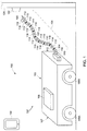
- FIG. 1 illustrates an embodiment of a snake-arm robot system 100 in accordance with the disclosure.
- the snake-arm robot system 100 includes a snake-arm robot 101 and a user device 130 .
- the user device 130 may be a wireless device such as a laptop computer, a mobile telephone, a tablet computer, and the like, or any other electronic device having wireless communications capability.
- the snake arm robot 101 includes a vehicle 102 (or introduction device) and an associated snake-arm 104 .
- the vehicle 102 includes wheels 106 A and 106 B, a drive motor (not shown) within a chassis 107 , and a server computer 108 .
- the snake-arm 104 includes a plurality of links 110 that each includes a controller 112 and a joint 114 between adjacent links.
- Each controller 112 can control a servomotor (not shown) which imparts a motion based on a serpenoid curve to an associated joint 114 of the snake-arm 104 .
- a robot head 116 includes at least one camera 118 and a tool 120 that can be used to perform work on a workpiece 122 (which in this example is affixed to a wall 124 ).
- the server computer 108 may include one or more processors, one or more communications components, and at least one storage device (not shown), wherein the storage device includes instructions configured to cause the server computer 108 to operate in the manner disclosed.
- the server computer 108 receives input from the user device 130 regarding a desired pose of the snake-arm robot 100 , which may be input by a user utilizing a user interface, in order to perform a function and/or do work on the workpiece 122 .
- the server computer 108 receives continuous image data from the camera 118 which can include environment data and workpiece 122 data.
- the server computer 108 Based on the desired pose data and the image data, in some embodiments the server computer 108 generates movement instructions or control data signals and then transmits the movement instructions to one or more of the controllers 112 and/or to the vehicle drive motor which cause the vehicle 102 and snake-arm 104 to move in a desired direction and at a desired speed resulting in moving the robot head 116 to a desired position or desired pose.
- the camera 118 may be an RGB sensor (“red, green, blue” sensor) which operates to extract RGB-based texture information, proximity information related to the surface of an object or objects, and temperature information (using infrared signals).
- RGB-based texture data, proximity data, and/or temperature data is extracted simultaneously using, for example, a RGB-D camera (a camera that extracts color and dense depth images).
- a RGB-D camera a camera that extracts color and dense depth images.
- an RGB camera is adequate to provide data for visual servoing (which may be abbreviated as “VS”), which is defined as vision-based robot control which uses feedback information extracted from an image sensor to control the motion of a robot.
- the image sensor (or sensors) 118 can be mounted on the robot head 116 of the snake-arm 104 , wherein the angle(s) and/or location(s) of the mounting position is/are flexible.
- the sensory information obtained from the camera 118 is processed on-board using hardware components, for example, system on chip (SoC) circuitry (not shown), or field-programmable gate array (FPGA) circuitry (not shown) or the like, and/or by using software algorithms.
- SoC system on chip
- FPGA field-programmable gate array
- the server computer 108 receives optical or visual data from the camera 118 (which may be an optical sensor) which is associated with the operating environment and/or the location of the workpiece 122 .
- the server computer 108 also receives input data from a user device (not shown, which may be a laptop computer, a mobile device, or other electronic device operated by a user), wherein the input data describes a desired pose of the snake-arm robot 100 and the robot head 116 , which may include a tool 120 .
- the difference between the desired image, which is associated with the desired pose, and the real-time captured image, will be used to compute a desired velocity using image Jacobians.
- the server computer 108 then translates a desired velocity of the robot head into incremental displacement data and rotation data within a control cycle, which is based on the visual data and the input data. Next, all the positions of the links 110 located after the robot head 116 are computed to follow the motion of the robot head 116 .
- a forward dynamics model is then applied to compute the current position of all the links 110 of the robot snake-arm 104 .
- the server computer 108 utilizes an incremental dynamics model to compute the force and torques required to move each of the joints 114 when the snake-arm robot 100 is to move to a desired configuration or pose.
- the server computer 108 then generates movement commands and transmits the movement commands to a drive motor (not shown) of the vehicle 102 and to the controllers 112 to cause servomotors (not shown) within the joints 114 of the snake-arm 104 to move so that the snake-arm robot 100 will move to the desired pose.
- the image data provided by the camera 118 and the input data provided by the user can be utilized to automatically move the snake-arm robot 100 , and specifically the robot head 116 , to a desired pose to either be in position to do work or to be in a position to perform work without requiring data from encoders (which would otherwise be required on the joints 114 to provide location data).
- FIG. 2 illustrates a system framework 200 which includes a first stage 202 and a second stage 204 in accordance with the disclosure.
- the first stage 202 includes a user interface 206 enabling a user to provide input information associated with a desired pose 208 of the robot head, and in some implementations a processor then generates a desired image 210 (which may be displayed to the user), and performs feature extraction 212 associated with that desired image 210 .
- the first stage 202 also includes a sensing system 214 having one or more sensors that collect image data of an object and perform onboard pre-processing of the data.
- the sensing system 214 extracts features 216 from the image data obtained from the work environment, wherein the features 216 can include a pose estimation 218 , basic features 220 , complex features 222 , and semantic features 224 .
- the first stage 202 then calculates a feature error 226 between the desired image and a real-time captured image based on the correspondence of features.
- the second stage 204 receives the feature error data 226 and generates an image Jacobian matrix 230 for a desired head pose (which will be explained in more detail below). Information from the image Jacobian matrix 230 is then utilized to determine desired camera configuration data 232 and a desired body configuration data 234 , which along with a current body configuration data 236 is utilized to generate an incremental dynamics model 238 which is then utilized to implement closed-loop dynamics control 240 of the snake-arm robot. An embodiment of the overall process is described in more detail below.
- a desired image 210 can be generated which is associated with the desired position of the robot head.
- the desired image 210 may be displayed to the user. This desired image 210 is the same as the one that would be captured by a camera if the snake-arm robot “actually” moved so that the robot head is in the desired position within the 3D work environment.
- the transformation data between the camera 118 and the robot head 116 may be different, which may cause different desired images to be generated.
- the first approach is to generate an image in a simulation environment by moving a simulated robot head with a simulated camera to the desired position and then taking a picture by using the simulated camera.
- the second approach is to generate an image in a projected 3D image environment by using projective geometry, as described below.
- the intrinsic matrix is parameterized as:
- K [ f x s x 0 0 f y y 0 0 0 1 ] ( 1 ) where f x and f y are focal lengths, x 0 and y 0 are principal point offset, and s is the Axis Skew.
- the desired image data 210 and the real-time captured images data are then analyzed online or offline to extract features 216 .
- the feature extraction data can represent images data such as basic features 220 such as corners, edges, lines, or planes, and up to high-level semantic feature 224 representations.
- basic features 220 conventional computer vision technology can be applied to analyze image data and then obtain the corners, edges, lines, and planes.
- complex features 222 the basic features can be combined together to form a set, which set of features may be more reliable for robots to use for further processing.
- the distribution or principals of the complex features can be analyzed to generate more robust descriptors.
- Features can also be used to describe a segmented object, and then the segmentation data and feature extraction data can be computed in an iterative manner to enhance reliability.
- tracking algorithms can also be utilized to obtain complex features data together with segmentation data.
- robots can estimate the pose of the objects or the image in 3D space (or the work environment).
- the benefits of estimating the pose include completing an overall understanding about the geometrical information of the target object(s) in the environment, which is more robust than pure feature-based approaches.
- semantic representations may include the semantic names, geometrical and affordance relationship among objects, spatial descriptions, and the like.
- Such semantic information can be represented by various data structures, including entries in a database, a graph, a tree, and the like. Using such an approach can largely improve the system performance and increase reliability.
- a feature refinement process may also be utilized, wherein the estimated 6D poses are used to refine the extracted features on images.
- 6D poses include the 3-dimensional position and the 3-dimensional rotation. Referring to equation (2) above, the 3D position is represented as t and the 3D rotation is represented as R.
- equation (1) and equation (2) above the locations of the pixels on the images can be determined, and then the pixels can be further analyzed to get refined.
- the detected features are projected back into the images based on the 6D poses. The comparison between the detected features and the projected features are used to re-estimate the estimated pose and also remove some false detected features.
- equation (1) and equation (2) above the locations of the pixels on the images can be determined, and then the pixels can be further analyzed to get refined.
- the detected features are projected back into the images based on the 6D poses.
- the comparison between the detected features and the projected features are used to re-estimate the estimated pose and also remove some false detected features.
- false detection data, and ignored features data can be further processed to provide more robust overall representations.
- the second stage 204 receives the feature error data 226 and generates an image Jacobian matrix 230 for a desired head pose.
- the feature error can be obtained by computing the error of the features on the images. The error between two consecutive images divided by the timing interval gives us the velocities of features on images.
- F u (t) and F v (t) are the locations of the features on images at time step t.
- FIG. 3A is an example of a perspective imaging system 300 using the image Jacobian in accordance with methods described herein.
- a camera 302 is pointed at an object 304 , and a coordinate frame “C” is associated with the camera, and the coordinate of the object 304 is expressed with regard to the camera coordinate frame.
- “f hat” represents the focal length of the lens in units of meters divided by the dimensions of the pixel, which is in units of meters per pixel (and thus the focal length here is expressed in units per pixel).
- the coordinate (u,v) 308 is the projection of the object 304 onto a two-dimensional plane.
- the camera 302 is shown attached to a vehicle 310 (which may represent a snake-arm robot) that can be moving in the direction of arrow 312 with a velocity (v x , v y , v z ), and which can also rotate in the direction of arrow 314 with an angular velocity (w x , w y , w z ).
- vehicle 310 which may represent a snake-arm robot
- FIG. 3B illustrates a known expression 320 relating the velocity of the camera 322 to the pixel velocity 324 in the image plane, and these two quantities are related by a Jacobian matrix 326 , which here is a two by six matrix.
- the camera's spatial velocity has a translational component and a rotational component, which when multiplied by the image Jacobian matrix provides the pixel velocity in the image plane, which is that velocity that the point (u, v) (See FIG. 3A ) in the image plane appears to move.
- Equation (3) Equation (3) above can be rewritten as:
- control signal is then computed as:
- V xyz [ V x ,V y ,V z ⁇ x , ⁇ y , ⁇ z ] T (8)
- T camera desired camera configuration
- the desired head configuration is:
- T robot (desired) T camera robot T camera (desired), where T camera robot is the fixed transformation between robot head and camera.
- incremental dynamics control 238 can be calculated as follows. At time 0, if all joints are supported by motor torques and the robot is static, the configuration of robots using the torques on joints can be computed. We can have the configuration description as: ⁇ 0 , ⁇ 0 ⁇ (10)
- ⁇ M ( ⁇ ) ⁇ umlaut over ( ⁇ ) ⁇ + C ( ⁇ , ⁇ dot over ( ⁇ ) ⁇ ) ⁇ dot over ( ⁇ ) ⁇ + g ( ⁇ ) (11)
- M( ⁇ ) ⁇ n ⁇ n is the inner mass matrix
- C( ⁇ ) ⁇ n ⁇ n is related to the Coriolis and the centrifugal matrix
- g( ⁇ ) ⁇ n ⁇ 1 is the gravitational torque/force.
- ⁇ is known from static force analysis, and ⁇ dot over ( ⁇ ) ⁇ and ⁇ umlaut over ( ⁇ ) ⁇ are computed from equation (8). Higher order derivatives of ⁇ are ignored, and then ⁇ dot over ( ⁇ ) ⁇ can be computed.
- the loop is closed by using the visual feedback information.
- the configuration of the snake-arm robot will be incrementally recomputed using equations (4), (6), (7), (8), and (9). The new configuration will then be used update the equation (10) to get the torque and joint angles for the next control cycle.
- each of the controllers 112 is associated with a servomotor (not shown) that is operable to move an associated joint 114 of the snake arm 104 to thus cause the robot head to move to the desired pose.
- FIG. 4 illustrates a flowchart of process 400 for using optical data to dynamically control a snake-arm robot according to some embodiments.
- a server computer receives 402 from at least one optical sensor mounted on a robot head of a snake-arm robot, real-time image data associated with at least one of an operating environment and a location of a workpiece, and receives 404 input data describing a desired pose of the robot head from a user device.
- the server computer then computes 406 a desired velocity of the robot head using an image Jacobian based on the difference between the desired pose and the real-time image data, and translates 408 the desired velocity of the robot head into incremental displacement data and rotation data within a control cycle based on the image data and the input data.
- the server computer computes 410 the position of each of a plurality of links of the snake-arm to follow the motion of the robot head; computes 412 a current position of each of the plurality of links utilizing a forward dynamics model; and computes 414 , using an incremental dynamics model force, force and torque data required to move at least one of the plurality of joints connecting the links of the snake arm so that the snake-arm robot moves to the desired pose.
- the server computer then generates 416 movement instructions based on the force and torque data, and transmits 418 the movement instructions to at least one of a drive motor associated with an introduction device and a plurality of controllers associated with servo-motors operably connected to joints connecting the links of the snake arm causing the robot head to move to the desired pose.
- a method and system for automatically controlling a snake-arm robot utilizing visual data obtained from an optical sensor, such as a camera, mounted on a robot head The challenges that have been overcome include implementing visual servoing for snake-arm robots, dynamic control without the use of encoders, closing the loop for both visual information and dynamics information, estimating snake-arm robot configuration based on force and/or torque data, and overall snake-arm robot control system design and integration.
- a key aspect is the use of visual feedback data and incremental dynamics control data for controlling a snake-arm robot.
- the visual servoing control loop advantageously increases the performance of the system by taking external feedback into the control, which also beneficially improves the overall accuracy of the system.
- the use of one additional resource in addition to the internal sensors improves the robustness of the system along with improving the accuracy of the snake-arm robot.
- the control loop is a closed system that uses visual feedback information and the incremental dynamics model, calibration of the snake-arm robot system is unnecessary for field testing and for other applications, resulting in a significant time savings for onsite work.
- the disclosed system level design can be utilized with conventional snake-arm robots (that do not include encoders) for many types of commercial applications including, but not limited to, visual information-based operations such as repairing aircraft engines, maintaining industrial equipment, transporting materials within confining environments, manufacturing parts, and the like.
- the methods and apparatus described herein significantly improves the performance of conventional snake arm robotic systems by automatically providing control data for moving a snake-arm robot to locate a target and closes the control loop for robust and accurate operations.
- the methods disclosed herein use external image information to close the control loop and provide an incremental dynamics model, which enables the snake-arm robot to perform many different types of operations in different environments.
- conventional snake-arm robots must be calibrated to the environment before executing operations, which is expensive and time consuming, whereas the described process does not require d calibration is not required when utilizing the disclosed methods which saves time and costs for customers.
Landscapes
- Engineering & Computer Science (AREA)
- Robotics (AREA)
- Mechanical Engineering (AREA)
- Computer Networks & Wireless Communication (AREA)
- Health & Medical Sciences (AREA)
- General Health & Medical Sciences (AREA)
- Orthopedic Medicine & Surgery (AREA)
- Manipulator (AREA)
Abstract
Description
where fx and fy are focal lengths, x0 and y0 are principal point offset, and s is the Axis Skew. With a known world model and a known snake-arm robot position, the points in the 3D world model can be projected to pixels on a two-dimensional (2D) image plane using the following equation:
P=K×[|t] (2)
where R is the rotation and t is the translation vector; then
V xyz=[V x ,V y ,V zωx,ωy,ωz]T (8)
x(t)=x(t−1)+V x dt
y(t)=y(t−1)+V y dt
z(t)=z(t−1)+V z dt (9)
α(t)=α(t−1)+ωx dt
β(t)=β(t−1)+ωy dt
γ(t)=γ(t−1)+ωz dt
{τ0,θ0} (10)
τ=M(θ){umlaut over (θ)}+C(θ,{dot over (θ)}){dot over (θ)}+g(θ) (11)
where M(θ) ∈
τ=τ0+∫{dot over (τ)}dt (13)
The loop is closed by using the visual feedback information. The configuration of the snake-arm robot will be incrementally recomputed using equations (4), (6), (7), (8), and (9). The new configuration will then be used update the equation (10) to get the torque and joint angles for the next control cycle.
Claims (20)
Priority Applications (2)
| Application Number | Priority Date | Filing Date | Title |
|---|---|---|---|
| US16/245,017 US11034026B2 (en) | 2019-01-10 | 2019-01-10 | Utilizing optical data to dynamically control operation of a snake-arm robot |
| US17/329,257 US11801607B2 (en) | 2019-01-10 | 2021-05-25 | Utilizing optical data to control operation of a snake-arm robot |
Applications Claiming Priority (1)
| Application Number | Priority Date | Filing Date | Title |
|---|---|---|---|
| US16/245,017 US11034026B2 (en) | 2019-01-10 | 2019-01-10 | Utilizing optical data to dynamically control operation of a snake-arm robot |
Related Child Applications (1)
| Application Number | Title | Priority Date | Filing Date |
|---|---|---|---|
| US17/329,257 Continuation US11801607B2 (en) | 2019-01-10 | 2021-05-25 | Utilizing optical data to control operation of a snake-arm robot |
Publications (2)
| Publication Number | Publication Date |
|---|---|
| US20200223069A1 US20200223069A1 (en) | 2020-07-16 |
| US11034026B2 true US11034026B2 (en) | 2021-06-15 |
Family
ID=71516290
Family Applications (2)
| Application Number | Title | Priority Date | Filing Date |
|---|---|---|---|
| US16/245,017 Active 2039-12-13 US11034026B2 (en) | 2019-01-10 | 2019-01-10 | Utilizing optical data to dynamically control operation of a snake-arm robot |
| US17/329,257 Active 2039-05-31 US11801607B2 (en) | 2019-01-10 | 2021-05-25 | Utilizing optical data to control operation of a snake-arm robot |
Family Applications After (1)
| Application Number | Title | Priority Date | Filing Date |
|---|---|---|---|
| US17/329,257 Active 2039-05-31 US11801607B2 (en) | 2019-01-10 | 2021-05-25 | Utilizing optical data to control operation of a snake-arm robot |
Country Status (1)
| Country | Link |
|---|---|
| US (2) | US11034026B2 (en) |
Cited By (1)
| Publication number | Priority date | Publication date | Assignee | Title |
|---|---|---|---|---|
| US20240198598A1 (en) * | 2022-12-15 | 2024-06-20 | International Business Machines Corporation | Three-dimensional printing using configurable movement tracks |
Families Citing this family (32)
| Publication number | Priority date | Publication date | Assignee | Title |
|---|---|---|---|---|
| CN109215080B (en) * | 2018-09-25 | 2020-08-11 | 清华大学 | 6D pose estimation network training method and device based on deep learning iterative matching |
| US11034026B2 (en) * | 2019-01-10 | 2021-06-15 | General Electric Company | Utilizing optical data to dynamically control operation of a snake-arm robot |
| US11179852B2 (en) | 2019-03-25 | 2021-11-23 | Dishcraft Robotics, Inc. | Automated manipulation of transparent vessels |
| US11030766B2 (en) * | 2019-03-25 | 2021-06-08 | Dishcraft Robotics, Inc. | Automated manipulation of transparent vessels |
| US11584004B2 (en) * | 2019-12-17 | 2023-02-21 | X Development Llc | Autonomous object learning by robots triggered by remote operators |
| CN114063557B (en) * | 2020-07-29 | 2024-03-22 | 创博股份有限公司 | How to control end-effector tracking objects in an arc path |
| CN114078092B (en) * | 2020-08-11 | 2025-07-01 | 中兴通讯股份有限公司 | Image processing method, device, electronic device and storage medium |
| CN111983631B (en) * | 2020-08-17 | 2023-11-21 | 云南电网有限责任公司电力科学研究院 | A snake-shaped power inspection robot positioning system for narrow and long confined spaces |
| US12139109B2 (en) | 2020-10-29 | 2024-11-12 | General Electric Company | Systems and methods of servicing equipment |
| US12511623B2 (en) | 2020-10-29 | 2025-12-30 | General Electric Company | Systems and methods of servicing equipment |
| US11938907B2 (en) * | 2020-10-29 | 2024-03-26 | Oliver Crispin Robotics Limited | Systems and methods of servicing equipment |
| US11874653B2 (en) | 2020-10-29 | 2024-01-16 | Oliver Crispin Robotics Limited | Systems and methods of servicing equipment |
| US12208925B2 (en) | 2020-10-29 | 2025-01-28 | General Electric Company | Systems and methods of servicing equipment |
| US11915531B2 (en) | 2020-10-29 | 2024-02-27 | General Electric Company | Systems and methods of servicing equipment |
| US11992952B2 (en) | 2020-10-29 | 2024-05-28 | General Electric Company | Systems and methods of servicing equipment |
| US11685051B2 (en) * | 2020-10-29 | 2023-06-27 | General Electric Company | Systems and methods of servicing equipment |
| US11935290B2 (en) | 2020-10-29 | 2024-03-19 | Oliver Crispin Robotics Limited | Systems and methods of servicing equipment |
| CN112549010B (en) * | 2020-12-22 | 2022-11-08 | 南昌大学 | Design method of adaptive trajectory tracking controller for multi-joint snake robot based on improved Serpenoid curve |
| CN112606001A (en) * | 2020-12-27 | 2021-04-06 | 中信重工开诚智能装备有限公司 | Electrolytic tank inspection robot control system and control method |
| CN112847362B (en) * | 2021-01-05 | 2022-09-20 | 江汉大学 | A Vision Servo Control Method for Handling Robot Based on Image Moment |
| CN112904866B (en) * | 2021-01-28 | 2023-04-21 | 西安建筑科技大学 | Inspection robot storage charging control method, system and outdoor inspection robot |
| US11752631B2 (en) * | 2021-02-09 | 2023-09-12 | Ford Global Technologies, Llc | Fleet inspection and maintenance mobile robot |
| CN113172659B (en) * | 2021-04-22 | 2023-06-09 | 哈尔滨工业大学(深圳) | Method and system for measuring the arm shape of a flexible robot based on equivalent center point recognition |
| CN113386130B (en) * | 2021-05-21 | 2023-02-03 | 北部湾大学 | Bionic snake-shaped robot control system and control method thereof |
| CN113686343B (en) * | 2021-08-24 | 2024-02-23 | 中国人民解放军93184部队 | Visual navigation method for serpentine mechanical arm to travel in aircraft air inlet channel |
| CN114131611B (en) * | 2021-12-16 | 2023-10-24 | 华中科技大学 | Joint error offline compensation method, system and terminal for robot gravity pose decomposition |
| CN116408771B (en) * | 2022-11-30 | 2026-02-17 | 哈尔滨工业大学(深圳) | A closed-loop control method and system for a linkage-type cable-driven flexible robotic arm |
| CN116000932B (en) * | 2022-12-30 | 2024-04-26 | 节卡机器人股份有限公司 | Motion equipment control method, system, device, equipment and storage medium |
| CN116985117B (en) * | 2023-06-06 | 2025-09-12 | 浙江大学高端装备研究院 | A method for end-following motion control of a snake-like redundant manipulator |
| CN116476078B (en) * | 2023-06-19 | 2023-09-05 | 安徽大学 | Laser radar-based stable target tracking method for snake-shaped robot |
| CN116687320B (en) * | 2023-08-07 | 2023-10-24 | 深圳英美达医疗技术有限公司 | Medical instrument control device |
| CN117549330B (en) * | 2024-01-11 | 2024-03-22 | 四川省铁路建设有限公司 | Construction safety monitoring robot system and control method |
Citations (22)
| Publication number | Priority date | Publication date | Assignee | Title |
|---|---|---|---|---|
| US5737500A (en) * | 1992-03-11 | 1998-04-07 | California Institute Of Technology | Mobile dexterous siren degree of freedom robot arm with real-time control system |
| US7171279B2 (en) | 2000-08-18 | 2007-01-30 | Oliver Crispin Robotics Limited | Articulating arm for positioning a tool at a location |
| US20100152899A1 (en) * | 2008-11-17 | 2010-06-17 | Energid Technologies, Inc. | Systems and methods of coordination control for robot manipulation |
| US20100234999A1 (en) * | 2006-06-26 | 2010-09-16 | Yuichiro Nakajima | Multi-joint robot and control program thereof |
| US20110184241A1 (en) * | 2008-06-05 | 2011-07-28 | Cardiorobotics, Inc. | Extendable articulated probe device |
| US20120158179A1 (en) * | 2010-12-20 | 2012-06-21 | Kabushiki Kaisha Toshiba | Robot control apparatus |
| US8374722B2 (en) | 2007-12-21 | 2013-02-12 | Oliver Crispin Robotics Limited | Robotic arm |
| US20130296885A1 (en) * | 2012-05-01 | 2013-11-07 | Jaydev P. Desai | Actuated steerable probe and systems and methods of using same |
| CN103479320A (en) | 2013-09-25 | 2014-01-01 | 深圳先进技术研究院 | Active snakelike endoscope robot system |
| US20140121837A1 (en) * | 2010-08-31 | 2014-05-01 | Kabushiki Kaisha Yaskawa Denki | Robot system, control device of robot, and robot control device |
| US20140195054A1 (en) * | 2011-09-15 | 2014-07-10 | Kabushiki Kaisha Yaskawa Denki | Robot system, robot control device and method for controlling robot |
| US20140330432A1 (en) * | 2012-04-20 | 2014-11-06 | Vanderbilt University | Systems and methods for safe compliant insertion and hybrid force/motion telemanipulation of continuum robots |
| CN204076245U (en) | 2014-05-20 | 2015-01-07 | 郑天江 | A kind of snake-shaped robot |
| CN104925159A (en) | 2015-07-05 | 2015-09-23 | 北京工业大学 | Reconnaissance type obstacle-surmounting machine snake |
| US9294737B2 (en) | 2012-08-23 | 2016-03-22 | Siemens Energy, Inc. | Flexible linkage camera system and method for visual inspection of off line industrial gas turbines and other power generation machinery |
| US20160303739A1 (en) * | 2014-04-10 | 2016-10-20 | Quanser Consulting Inc. | Robotic Systems and Methods of Operating Robotic Systems |
| US20170361470A1 (en) | 2016-06-21 | 2017-12-21 | Ansaldo Energia Ip Uk Limited | Robotic system for confined space operations |
| US20180021094A1 (en) * | 2015-03-23 | 2018-01-25 | Sony Production | Medical support arm device and method of controlling medical support arm device |
| US20180021945A1 (en) | 2015-01-29 | 2018-01-25 | Eelume As | Underwater manipulator arm robot |
| US9956042B2 (en) * | 2012-01-13 | 2018-05-01 | Vanderbilt University | Systems and methods for robot-assisted transurethral exploration and intervention |
| US20190358813A1 (en) * | 2018-05-23 | 2019-11-28 | General Electric Company | System and Method for Controlling a Robotic Arm |
| US20200223069A1 (en) * | 2019-01-10 | 2020-07-16 | General Electric Company | Utilizing optical data to dynamically control operation of a snake-arm robot |
Family Cites Families (4)
| Publication number | Priority date | Publication date | Assignee | Title |
|---|---|---|---|---|
| US8160743B2 (en) * | 2005-08-16 | 2012-04-17 | Brainlab Ag | Anthropomorphic medical robot arm with movement restrictions |
| US7930065B2 (en) * | 2005-12-30 | 2011-04-19 | Intuitive Surgical Operations, Inc. | Robotic surgery system including position sensors using fiber bragg gratings |
| US8620473B2 (en) * | 2007-06-13 | 2013-12-31 | Intuitive Surgical Operations, Inc. | Medical robotic system with coupled control modes |
| US9226796B2 (en) * | 2012-08-03 | 2016-01-05 | Stryker Corporation | Method for detecting a disturbance as an energy applicator of a surgical instrument traverses a cutting path |
-
2019
- 2019-01-10 US US16/245,017 patent/US11034026B2/en active Active
-
2021
- 2021-05-25 US US17/329,257 patent/US11801607B2/en active Active
Patent Citations (24)
| Publication number | Priority date | Publication date | Assignee | Title |
|---|---|---|---|---|
| US5737500A (en) * | 1992-03-11 | 1998-04-07 | California Institute Of Technology | Mobile dexterous siren degree of freedom robot arm with real-time control system |
| US7171279B2 (en) | 2000-08-18 | 2007-01-30 | Oliver Crispin Robotics Limited | Articulating arm for positioning a tool at a location |
| US20100234999A1 (en) * | 2006-06-26 | 2010-09-16 | Yuichiro Nakajima | Multi-joint robot and control program thereof |
| US8374722B2 (en) | 2007-12-21 | 2013-02-12 | Oliver Crispin Robotics Limited | Robotic arm |
| US20110184241A1 (en) * | 2008-06-05 | 2011-07-28 | Cardiorobotics, Inc. | Extendable articulated probe device |
| US20100152899A1 (en) * | 2008-11-17 | 2010-06-17 | Energid Technologies, Inc. | Systems and methods of coordination control for robot manipulation |
| US20140121837A1 (en) * | 2010-08-31 | 2014-05-01 | Kabushiki Kaisha Yaskawa Denki | Robot system, control device of robot, and robot control device |
| US20120158179A1 (en) * | 2010-12-20 | 2012-06-21 | Kabushiki Kaisha Toshiba | Robot control apparatus |
| US20140195054A1 (en) * | 2011-09-15 | 2014-07-10 | Kabushiki Kaisha Yaskawa Denki | Robot system, robot control device and method for controlling robot |
| US9956042B2 (en) * | 2012-01-13 | 2018-05-01 | Vanderbilt University | Systems and methods for robot-assisted transurethral exploration and intervention |
| US20140330432A1 (en) * | 2012-04-20 | 2014-11-06 | Vanderbilt University | Systems and methods for safe compliant insertion and hybrid force/motion telemanipulation of continuum robots |
| US20130296885A1 (en) * | 2012-05-01 | 2013-11-07 | Jaydev P. Desai | Actuated steerable probe and systems and methods of using same |
| US9294737B2 (en) | 2012-08-23 | 2016-03-22 | Siemens Energy, Inc. | Flexible linkage camera system and method for visual inspection of off line industrial gas turbines and other power generation machinery |
| CN103479320A (en) | 2013-09-25 | 2014-01-01 | 深圳先进技术研究院 | Active snakelike endoscope robot system |
| CN103479320B (en) | 2013-09-25 | 2015-08-26 | 深圳先进技术研究院 | Active snakelike endoscope robot system |
| US20160303739A1 (en) * | 2014-04-10 | 2016-10-20 | Quanser Consulting Inc. | Robotic Systems and Methods of Operating Robotic Systems |
| CN204076245U (en) | 2014-05-20 | 2015-01-07 | 郑天江 | A kind of snake-shaped robot |
| US20180021945A1 (en) | 2015-01-29 | 2018-01-25 | Eelume As | Underwater manipulator arm robot |
| US20180021094A1 (en) * | 2015-03-23 | 2018-01-25 | Sony Production | Medical support arm device and method of controlling medical support arm device |
| CN104925159B (en) | 2015-07-05 | 2017-04-05 | 北京工业大学 | A kind of reconnaissance version can obstacle detouring snake robot |
| CN104925159A (en) | 2015-07-05 | 2015-09-23 | 北京工业大学 | Reconnaissance type obstacle-surmounting machine snake |
| US20170361470A1 (en) | 2016-06-21 | 2017-12-21 | Ansaldo Energia Ip Uk Limited | Robotic system for confined space operations |
| US20190358813A1 (en) * | 2018-05-23 | 2019-11-28 | General Electric Company | System and Method for Controlling a Robotic Arm |
| US20200223069A1 (en) * | 2019-01-10 | 2020-07-16 | General Electric Company | Utilizing optical data to dynamically control operation of a snake-arm robot |
Non-Patent Citations (2)
| Title |
|---|
| Delisle, Jean-Jacques, "How this snake-like robot with vision systems and laser cutters helps repair aircraft engines", Electronic Products, Sep. 11, 2017, 4pgs. |
| Hasanabadi, E. et al., "Trajectory Tracking of a Planar Snake Robot Using Camera Feedback", IEEE Xplore, Dec. 27, 2011, 4pgs. |
Cited By (2)
| Publication number | Priority date | Publication date | Assignee | Title |
|---|---|---|---|---|
| US20240198598A1 (en) * | 2022-12-15 | 2024-06-20 | International Business Machines Corporation | Three-dimensional printing using configurable movement tracks |
| US12337545B2 (en) * | 2022-12-15 | 2025-06-24 | International Business Machines Corporation | Three-dimensional printing using configurable movement tracks |
Also Published As
| Publication number | Publication date |
|---|---|
| US11801607B2 (en) | 2023-10-31 |
| US20200223069A1 (en) | 2020-07-16 |
| US20210283784A1 (en) | 2021-09-16 |
Similar Documents
| Publication | Publication Date | Title |
|---|---|---|
| US11801607B2 (en) | Utilizing optical data to control operation of a snake-arm robot | |
| Dong et al. | Position-based visual servo control of autonomous robotic manipulators | |
| Ollero et al. | The aeroarms project: Aerial robots with advanced manipulation capabilities for inspection and maintenance | |
| Du et al. | Online robot kinematic calibration using hybrid filter with multiple sensors | |
| Melchiorre et al. | Collison avoidance using point cloud data fusion from multiple depth sensors: a practical approach | |
| CN110385694B (en) | Robot motion teaching device, robot system, and robot control device | |
| CN104057453B (en) | Robot device and method of manufacturing workpiece | |
| CN112634318B (en) | A teleoperating system and method for an underwater maintenance robot | |
| Ponte et al. | Visual sensing for developing autonomous behavior in snake robots | |
| CN101419055A (en) | Space target position and pose measuring device and method based on vision | |
| CN104570731A (en) | Uncalibrated human-computer interaction control system and method based on Kinect | |
| Andreff et al. | Image-based visual servoing of a gough—Stewart parallel manipulator using leg observations | |
| CN116438426A (en) | Apparatus and methods for measuring, inspecting or processing objects | |
| Xu et al. | Autonomous target capturing of free-floating space robot: Theory and experiments | |
| Thomas et al. | Multi sensor fusion in robot assembly using particle filters | |
| Sharma et al. | A framework for robot motion planning with sensor constraints | |
| CN109542094A (en) | Mobile robot visual point stabilization without desired image | |
| Karam et al. | Integrating a low-cost mems imu into a laser-based slam for indoor mobile mapping | |
| Fang et al. | A motion tracking method by combining the IMU and camera in mobile devices | |
| Han et al. | Grasping control method of manipulator based on binocular vision combining target detection and trajectory planning | |
| Kanellakis et al. | Guidance for autonomous aerial manipulator using stereo vision | |
| Allotta et al. | On the use of linear camera-object interaction models in visual servoing | |
| Nakhaeinia et al. | Adaptive robotic contour following from low accuracy RGB-D surface profiling and visual servoing | |
| JPH0795560A (en) | Image measuring method of remote control system, its apparatus, and distance measuring method | |
| JP2005186193A (en) | Robot calibration method and three-dimensional position measurement method |
Legal Events
| Date | Code | Title | Description |
|---|---|---|---|
| AS | Assignment |
Owner name: GENERAL ELECTRIC COMPANY, NEW YORK Free format text: ASSIGNMENT OF ASSIGNORS INTEREST;ASSIGNORS:TAN, HUAN;BIAN, XIAO;DANKO, TODD;SIGNING DATES FROM 20190107 TO 20190110;REEL/FRAME:047959/0946 |
|
| FEPP | Fee payment procedure |
Free format text: ENTITY STATUS SET TO UNDISCOUNTED (ORIGINAL EVENT CODE: BIG.); ENTITY STATUS OF PATENT OWNER: LARGE ENTITY |
|
| STPP | Information on status: patent application and granting procedure in general |
Free format text: NOTICE OF ALLOWANCE MAILED -- APPLICATION RECEIVED IN OFFICE OF PUBLICATIONS |
|
| STPP | Information on status: patent application and granting procedure in general |
Free format text: PUBLICATIONS -- ISSUE FEE PAYMENT RECEIVED |
|
| STPP | Information on status: patent application and granting procedure in general |
Free format text: PUBLICATIONS -- ISSUE FEE PAYMENT VERIFIED |
|
| STCF | Information on status: patent grant |
Free format text: PATENTED CASE |
|
| MAFP | Maintenance fee payment |
Free format text: PAYMENT OF MAINTENANCE FEE, 4TH YEAR, LARGE ENTITY (ORIGINAL EVENT CODE: M1551); ENTITY STATUS OF PATENT OWNER: LARGE ENTITY Year of fee payment: 4 |