EP3456462B1 - Werkzeugmaschine zur bearbeitung eines werkstücks - Google Patents
Werkzeugmaschine zur bearbeitung eines werkstücks Download PDFInfo
- Publication number
- EP3456462B1 EP3456462B1 EP18194741.7A EP18194741A EP3456462B1 EP 3456462 B1 EP3456462 B1 EP 3456462B1 EP 18194741 A EP18194741 A EP 18194741A EP 3456462 B1 EP3456462 B1 EP 3456462B1
- Authority
- EP
- European Patent Office
- Prior art keywords
- machining unit
- machine tool
- drive mechanism
- suspension
- disposed
- Prior art date
- Legal status (The legal status is an assumption and is not a legal conclusion. Google has not performed a legal analysis and makes no representation as to the accuracy of the status listed.)
- Active
Links
Images


Classifications
-
- B—PERFORMING OPERATIONS; TRANSPORTING
- B23—MACHINE TOOLS; METAL-WORKING NOT OTHERWISE PROVIDED FOR
- B23Q—DETAILS, COMPONENTS, OR ACCESSORIES FOR MACHINE TOOLS, e.g. ARRANGEMENTS FOR COPYING OR CONTROLLING; MACHINE TOOLS IN GENERAL CHARACTERISED BY THE CONSTRUCTION OF PARTICULAR DETAILS OR COMPONENTS; COMBINATIONS OR ASSOCIATIONS OF METAL-WORKING MACHINES, NOT DIRECTED TO A PARTICULAR RESULT
- B23Q11/00—Accessories fitted to machine tools for keeping tools or parts of the machine in good working condition or for cooling work; Safety devices specially combined with or arranged in, or specially adapted for use in connection with, machine tools
- B23Q11/001—Arrangements compensating weight or flexion on parts of the machine
- B23Q11/0017—Arrangements compensating weight or flexion on parts of the machine compensating the weight of vertically moving elements, e.g. by balancing liftable machine parts
-
- B—PERFORMING OPERATIONS; TRANSPORTING
- B23—MACHINE TOOLS; METAL-WORKING NOT OTHERWISE PROVIDED FOR
- B23Q—DETAILS, COMPONENTS, OR ACCESSORIES FOR MACHINE TOOLS, e.g. ARRANGEMENTS FOR COPYING OR CONTROLLING; MACHINE TOOLS IN GENERAL CHARACTERISED BY THE CONSTRUCTION OF PARTICULAR DETAILS OR COMPONENTS; COMBINATIONS OR ASSOCIATIONS OF METAL-WORKING MACHINES, NOT DIRECTED TO A PARTICULAR RESULT
- B23Q1/00—Members which are comprised in the general build-up of a form of machine, particularly relatively large fixed members
- B23Q1/25—Movable or adjustable work or tool supports
- B23Q1/26—Movable or adjustable work or tool supports characterised by constructional features relating to the co-operation of relatively movable members; Means for preventing relative movement of such members
-
- B—PERFORMING OPERATIONS; TRANSPORTING
- B23—MACHINE TOOLS; METAL-WORKING NOT OTHERWISE PROVIDED FOR
- B23C—MILLING
- B23C1/00—Milling machines not designed for particular work or special operations
- B23C1/002—Gantry-type milling machines
-
- B—PERFORMING OPERATIONS; TRANSPORTING
- B23—MACHINE TOOLS; METAL-WORKING NOT OTHERWISE PROVIDED FOR
- B23Q—DETAILS, COMPONENTS, OR ACCESSORIES FOR MACHINE TOOLS, e.g. ARRANGEMENTS FOR COPYING OR CONTROLLING; MACHINE TOOLS IN GENERAL CHARACTERISED BY THE CONSTRUCTION OF PARTICULAR DETAILS OR COMPONENTS; COMBINATIONS OR ASSOCIATIONS OF METAL-WORKING MACHINES, NOT DIRECTED TO A PARTICULAR RESULT
- B23Q1/00—Members which are comprised in the general build-up of a form of machine, particularly relatively large fixed members
- B23Q1/01—Frames, beds, pillars or like members; Arrangement of ways
- B23Q1/012—Portals
-
- B—PERFORMING OPERATIONS; TRANSPORTING
- B23—MACHINE TOOLS; METAL-WORKING NOT OTHERWISE PROVIDED FOR
- B23Q—DETAILS, COMPONENTS, OR ACCESSORIES FOR MACHINE TOOLS, e.g. ARRANGEMENTS FOR COPYING OR CONTROLLING; MACHINE TOOLS IN GENERAL CHARACTERISED BY THE CONSTRUCTION OF PARTICULAR DETAILS OR COMPONENTS; COMBINATIONS OR ASSOCIATIONS OF METAL-WORKING MACHINES, NOT DIRECTED TO A PARTICULAR RESULT
- B23Q1/00—Members which are comprised in the general build-up of a form of machine, particularly relatively large fixed members
- B23Q1/01—Frames, beds, pillars or like members; Arrangement of ways
- B23Q1/015—Frames, beds, pillars
-
- B—PERFORMING OPERATIONS; TRANSPORTING
- B23—MACHINE TOOLS; METAL-WORKING NOT OTHERWISE PROVIDED FOR
- B23Q—DETAILS, COMPONENTS, OR ACCESSORIES FOR MACHINE TOOLS, e.g. ARRANGEMENTS FOR COPYING OR CONTROLLING; MACHINE TOOLS IN GENERAL CHARACTERISED BY THE CONSTRUCTION OF PARTICULAR DETAILS OR COMPONENTS; COMBINATIONS OR ASSOCIATIONS OF METAL-WORKING MACHINES, NOT DIRECTED TO A PARTICULAR RESULT
- B23Q1/00—Members which are comprised in the general build-up of a form of machine, particularly relatively large fixed members
- B23Q1/01—Frames, beds, pillars or like members; Arrangement of ways
- B23Q1/017—Arrangements of ways
-
- B—PERFORMING OPERATIONS; TRANSPORTING
- B23—MACHINE TOOLS; METAL-WORKING NOT OTHERWISE PROVIDED FOR
- B23Q—DETAILS, COMPONENTS, OR ACCESSORIES FOR MACHINE TOOLS, e.g. ARRANGEMENTS FOR COPYING OR CONTROLLING; MACHINE TOOLS IN GENERAL CHARACTERISED BY THE CONSTRUCTION OF PARTICULAR DETAILS OR COMPONENTS; COMBINATIONS OR ASSOCIATIONS OF METAL-WORKING MACHINES, NOT DIRECTED TO A PARTICULAR RESULT
- B23Q1/00—Members which are comprised in the general build-up of a form of machine, particularly relatively large fixed members
- B23Q1/25—Movable or adjustable work or tool supports
- B23Q1/44—Movable or adjustable work or tool supports using particular mechanisms
- B23Q1/48—Movable or adjustable work or tool supports using particular mechanisms with sliding pairs and rotating pairs
- B23Q1/4804—Movable or adjustable work or tool supports using particular mechanisms with sliding pairs and rotating pairs a single rotating pair followed perpendicularly by a single sliding pair
- B23Q1/4809—Movable or adjustable work or tool supports using particular mechanisms with sliding pairs and rotating pairs a single rotating pair followed perpendicularly by a single sliding pair followed perpendicularly by a single rotating pair
-
- B—PERFORMING OPERATIONS; TRANSPORTING
- B23—MACHINE TOOLS; METAL-WORKING NOT OTHERWISE PROVIDED FOR
- B23Q—DETAILS, COMPONENTS, OR ACCESSORIES FOR MACHINE TOOLS, e.g. ARRANGEMENTS FOR COPYING OR CONTROLLING; MACHINE TOOLS IN GENERAL CHARACTERISED BY THE CONSTRUCTION OF PARTICULAR DETAILS OR COMPONENTS; COMBINATIONS OR ASSOCIATIONS OF METAL-WORKING MACHINES, NOT DIRECTED TO A PARTICULAR RESULT
- B23Q5/00—Driving or feeding mechanisms; Control arrangements therefor
- B23Q5/22—Feeding members carrying tools or work
- B23Q5/34—Feeding other members supporting tools or work, e.g. saddles, tool-slides, through mechanical transmission
- B23Q5/38—Feeding other members supporting tools or work, e.g. saddles, tool-slides, through mechanical transmission feeding continuously
- B23Q5/385—Feeding other members supporting tools or work, e.g. saddles, tool-slides, through mechanical transmission feeding continuously using a gear and rack mechanism or a friction wheel co-operating with a rail
-
- B—PERFORMING OPERATIONS; TRANSPORTING
- B23—MACHINE TOOLS; METAL-WORKING NOT OTHERWISE PROVIDED FOR
- B23Q—DETAILS, COMPONENTS, OR ACCESSORIES FOR MACHINE TOOLS, e.g. ARRANGEMENTS FOR COPYING OR CONTROLLING; MACHINE TOOLS IN GENERAL CHARACTERISED BY THE CONSTRUCTION OF PARTICULAR DETAILS OR COMPONENTS; COMBINATIONS OR ASSOCIATIONS OF METAL-WORKING MACHINES, NOT DIRECTED TO A PARTICULAR RESULT
- B23Q5/00—Driving or feeding mechanisms; Control arrangements therefor
- B23Q5/22—Feeding members carrying tools or work
- B23Q5/34—Feeding other members supporting tools or work, e.g. saddles, tool-slides, through mechanical transmission
- B23Q5/38—Feeding other members supporting tools or work, e.g. saddles, tool-slides, through mechanical transmission feeding continuously
- B23Q5/40—Feeding other members supporting tools or work, e.g. saddles, tool-slides, through mechanical transmission feeding continuously by feed shaft, e.g. lead screw
-
- B—PERFORMING OPERATIONS; TRANSPORTING
- B23—MACHINE TOOLS; METAL-WORKING NOT OTHERWISE PROVIDED FOR
- B23Q—DETAILS, COMPONENTS, OR ACCESSORIES FOR MACHINE TOOLS, e.g. ARRANGEMENTS FOR COPYING OR CONTROLLING; MACHINE TOOLS IN GENERAL CHARACTERISED BY THE CONSTRUCTION OF PARTICULAR DETAILS OR COMPONENTS; COMBINATIONS OR ASSOCIATIONS OF METAL-WORKING MACHINES, NOT DIRECTED TO A PARTICULAR RESULT
- B23Q2701/00—Members which are comprised in the general build-up of a form of the machine
- B23Q2701/02—Movable or adjustable work or tool supports for milling machines, their drive, control or guiding
-
- B—PERFORMING OPERATIONS; TRANSPORTING
- B23—MACHINE TOOLS; METAL-WORKING NOT OTHERWISE PROVIDED FOR
- B23Q—DETAILS, COMPONENTS, OR ACCESSORIES FOR MACHINE TOOLS, e.g. ARRANGEMENTS FOR COPYING OR CONTROLLING; MACHINE TOOLS IN GENERAL CHARACTERISED BY THE CONSTRUCTION OF PARTICULAR DETAILS OR COMPONENTS; COMBINATIONS OR ASSOCIATIONS OF METAL-WORKING MACHINES, NOT DIRECTED TO A PARTICULAR RESULT
- B23Q2705/00—Driving working spindles or feeding members carrying tools or work
- B23Q2705/10—Feeding members carrying tools or work
- B23Q2705/18—Feeding other members supporting tools also feeding working spindles supports
-
- Y—GENERAL TAGGING OF NEW TECHNOLOGICAL DEVELOPMENTS; GENERAL TAGGING OF CROSS-SECTIONAL TECHNOLOGIES SPANNING OVER SEVERAL SECTIONS OF THE IPC; TECHNICAL SUBJECTS COVERED BY FORMER USPC CROSS-REFERENCE ART COLLECTIONS [XRACs] AND DIGESTS
- Y10—TECHNICAL SUBJECTS COVERED BY FORMER USPC
- Y10T—TECHNICAL SUBJECTS COVERED BY FORMER US CLASSIFICATION
- Y10T409/00—Gear cutting, milling, or planing
- Y10T409/30—Milling
- Y10T409/30784—Milling including means to adustably position cutter
- Y10T409/307952—Linear adjustment
- Y10T409/308232—Linear adjustment and angular adjustment
-
- Y—GENERAL TAGGING OF NEW TECHNOLOGICAL DEVELOPMENTS; GENERAL TAGGING OF CROSS-SECTIONAL TECHNOLOGIES SPANNING OVER SEVERAL SECTIONS OF THE IPC; TECHNICAL SUBJECTS COVERED BY FORMER USPC CROSS-REFERENCE ART COLLECTIONS [XRACs] AND DIGESTS
- Y10—TECHNICAL SUBJECTS COVERED BY FORMER USPC
- Y10T—TECHNICAL SUBJECTS COVERED BY FORMER US CLASSIFICATION
- Y10T409/00—Gear cutting, milling, or planing
- Y10T409/30—Milling
- Y10T409/30784—Milling including means to adustably position cutter
- Y10T409/307952—Linear adjustment
- Y10T409/308288—Linear adjustment including gantry-type cutter-carrier
-
- Y—GENERAL TAGGING OF NEW TECHNOLOGICAL DEVELOPMENTS; GENERAL TAGGING OF CROSS-SECTIONAL TECHNOLOGIES SPANNING OVER SEVERAL SECTIONS OF THE IPC; TECHNICAL SUBJECTS COVERED BY FORMER USPC CROSS-REFERENCE ART COLLECTIONS [XRACs] AND DIGESTS
- Y10—TECHNICAL SUBJECTS COVERED BY FORMER USPC
- Y10T—TECHNICAL SUBJECTS COVERED BY FORMER US CLASSIFICATION
- Y10T409/00—Gear cutting, milling, or planing
- Y10T409/30—Milling
- Y10T409/309576—Machine frame
- Y10T409/309744—Machine frame including means to compensate for deformation
Definitions
- the present invention relates to a machine tool for machining a workpiece.
- the tool-carrying machining unit plays a significant role in ensuring the accuracy of the manufactured parts, as it performs the material removal processes directly on the workpiece using the tool carried by the tool-carrying machining unit. Therefore, it is particularly important that the tool-carrying machining unit applies the contour defined by specified parameters to the workpiece as precisely as possible.
- the design of the machine tool itself can also have a significant influence on the extent of the correction of the control parameters, for example, when masses within the machine tool shift due to the infeed of the numerically controlled axes. This can lead to significant deviations in the actual position of the tool of the machining unit mounted in the work spindle, although these deviations can sometimes be difficult to correct using complex path corrections of the numerically controlled axes.
- the DE 200 19 035 U1 a machine tool which has two racks for moving the work spindle in the vertical direction, wherein the work spindle can additionally be pivoted about a pivot axis.
- An object of the present invention is therefore to provide a machine tool with which the above problem can be avoided, in particular so that a simplified path correction is possible and at the same time the accuracy of the machining process is improved.
- the invention proposes a machine tool for machining a workpiece according to claim 1.
- the dependent claims relate to advantageous embodiments of the machine tool according to the invention.
- the machine tool according to the invention for machining a workpiece is defined in claim 1.
- the inventive design of the machine tool whereby the center of gravity of the machining unit is positioned so that it lies either within the effective point of the suspension or on a vertically oriented straight line passing through the effective point, makes it possible for the vertical and horizontal guides of the machining unit to be subjected to either a negligibly small torque, e.g. in the case of the vertical guide, or a constant torque, e.g. in the case of the horizontal guides, which is generated by the mass of the machining unit and the distance from the effective point of the suspension.
- This measure facilitates path correction of the corresponding numerically controllable axes, as the vertical position of the machining unit, which significantly influences the torques occurring in the guides in a conventional machine tool design, needs to be taken into account to a much lesser extent.
- the drive mechanism is carried along with the machining unit in order to increase the mass of the machining unit. This allows the machining unit to react more slowly to sudden forces during the machining process of the workpiece, which in turn can have a positive influence on the result of the machining process.
- the machine tool can be designed such that the effective point of the suspension in the case of a gearbox is arranged in the suspension itself.
- a further advantageous development of the machine tool according to the invention is that the machining unit is suspended from the one or more gear sections of the at least two gears of the drive mechanism in such a way that a constant torque acts on the carrier section in the vertical direction during the movement.
- the machining unit can also be suspended from the one or more gear sections of the one gear in such a way that a constant torque acts on the carrier section during the movement in the vertical direction.
- the machine tool according to the invention can be advantageously further developed in that the machining unit is suspended from the one or more gear sections of the at least two gears of the drive mechanism in such a way that during the movement in the vertical direction, essentially no torque acts on the at least one vertical guide of the carrier section.
- the machining unit can also be suspended from the one or more gear sections of the one gear that during the movement in the vertical direction, essentially no torque acts on the at least one vertical guide of the carrier section.
- the drive mechanism of the machine tool can be arranged such that the drive mechanism maintains its relative position to the support section during the movement of the machining unit in the vertical direction and the relative position of the point of action of the suspension to the machining unit remains substantially constant.
- both the drive mechanism and the point of action of the suspension can be arranged in such a way that they maintain their relative position to the support section during the movement of the machining unit in the vertical direction.
- both the drive mechanism and the point of action of the suspension can be arranged in such a way that they maintain their relative position to the machining unit during the movement of the machining unit in the vertical direction.
- One advantage may be that the drive of the drive mechanism, which also represents a heat source, remains on the support or support section of the machining unit, while the effective point or a suspension point of the suspension is moved with the machining unit.
- the machine tool according to the invention can be advantageously further developed in that during the movement of the machining unit the effective point of the suspension and/or the center of gravity of the machining unit move along the vertically oriented straight line.
- the machine tool according to the invention can be advantageously further developed in that the drive mechanism is designed as a self-locking drive mechanism.
- a self-locking drive mechanism makes it possible to position the machining unit along the vertical axis, whereby no further securing measures or locking devices are necessary in this position, since the drive mechanism does not allow any further adjustment of the position of the machining unit without being moved by the drive.
- the machine tool according to the invention can also be advantageously further developed in that the drive mechanism comprises at least one screw drive, preferably at least one ball screw drive.
- a screw drive is known as an implementation of a self-locking drive mechanism, which, due to a corresponding thread pitch, only allows an adjustment of the vertical position of the machining unit if the thread-bearing element (threaded element, e.g. a threaded rod with a ball screw, trapezoidal thread or another thread form) is driven accordingly by an electric, pneumatic or hydraulic drive.
- thread-bearing element threade.g. a threaded rod with a ball screw, trapezoidal thread or another thread form
- An advantageous development of the machine tool according to the invention consists in that, in a gear, the at least one vertical guide of the machining unit is arranged such that the center of gravity of the machining unit is displaced substantially concentrically to a threaded rod of the screw drive when the machining unit is moved in the vertical direction, in particular along the vertically oriented straight line.
- the machine tool according to the invention can be advantageously further developed in that the threaded rod is arranged axially with the vertically oriented straight line.
- the drive mechanism for example, has a drive and a gear to move the machining unit along the vertical direction, it can be extremely advantageous to place the center of gravity of the machining unit directly at the point of Suspension (suspension point).
- the center of gravity would now be directly in the cross-section of the threaded rod, which would place the threaded rod exclusively under tensile or compressive loads, while at the same time essentially freeing the vertical guidance of the machining unit from the torque generated by the distance between the center of gravity of the machining unit and the guide line of the guides. This enables significantly more precise guidance of the machining unit in the vertical direction, as the forces acting on the guide are significantly reduced.
- the machine tool according to the invention can be advantageously further developed in that the drive mechanism comprises at least one gear-rack combination, preferably at least one helical gear-rack combination.
- the drive mechanism can be designed in the form of a rack with a corresponding driving gear, whereby this embodiment does not have the self-locking properties of a screw drive.
- the machine tool according to the invention can be advantageously further developed in that, in the case of a gear, the at least one vertical guide of the machining unit is arranged in such a way that the center of gravity of the machining unit is guided essentially at the contact point of the pitch circle of the gear wheel and the pitch line of the rack when the machining unit is moved in the vertical direction.
- the drive mechanism for example, has a drive and a gear for moving the machining unit along the vertical direction, to place the center of gravity of the machining unit directly at the suspension point (the suspension point here is the contact point between the pitch circle of the gear and the pitch line of the rack).
- the rack would be subjected exclusively to tensile or compressive loads, and at the same time, the vertical guidance of the machining unit would be essentially freed from the absorption of a torque generated due to the distance between the center of gravity of the machining unit and the guide line of the guides. This can enable significantly more precise guidance of the machining unit in the vertical direction, as the forces acting on the guide are considerably reduced.
- the machine tool according to the invention can be advantageously further developed in that the machining unit comprises a spindle carrier carrying a work spindle.
- the machine tool according to the invention can be advantageously further developed in that the spindle carrier comprises a pivoting device for pivoting the work spindle about a pivot axis.
- the spindle support allows it to be pivoted through a wide angular range, e.g., from +90° to -90° for vertical alignment of the work spindle.
- the angular range can also be selected to be larger. This may depend, for example, on the bending behavior of the work spindle's supply lines.
- the pivot axis is arranged perpendicularly or obliquely, preferably at a 45° angle, to a spindle axis of the work spindle.
- a particularly advantageous development of the machine tool according to the invention results from the fact that a pivotable section of the spindle carrier holding the work spindle, with which the work spindle can be pivoted about the pivot axis, is arranged in such a way that a common center of gravity of the pivotable section and the work spindle lies at the intersection point of the pivot axis and the vertically oriented straight line.
- a further advantageous development of the machine tool according to the invention consists in that the support section is designed as a machine stand arranged on a machine bed.
- the machine tool according to the invention can be advantageously further developed in that the carrier section comprises a horizontally movable slide section.
- the machine tool according to the invention can be advantageously further developed in that the slide section is mounted on guides on a horizontally movable portal structure of a gantry machine tool.
- the design of the suspension of the machine tool according to the invention can be applied to a movable portal structure of a gantry machine tool.
- the inventive machine tool for machining a workpiece has simplified the necessary corrections to the paths of the guided elements, since the masses moved during the feed of the machining unit now generate either a constant torque in the guides or, in certain guides, even a negligibly small torque, regardless of the vertical position of the machining unit, which otherwise had a significant influence on the acting torques.
- This can be advantageously used when correcting the paths for the numerically controllable axes, which in turn leads to increased manufacturing accuracy, as the geometric accuracy of the machine tool has been improved.
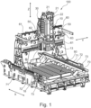
- Fig. 1 shows, by way of example, a schematic perspective view of an embodiment of a machine tool 100 according to the invention.
- the machine tool 100 is constructed, for example, in a gantry design and has a machine bed 70 which can be set up on adjustable feet and on which, for example, a workpiece clamping table 80 is arranged, on which workpieces can be clamped for machining.
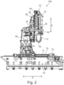
- Fig. 2 shows, by way of example, a schematic side view of an embodiment of the machine tool according to the invention from Fig. 1 .
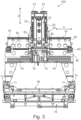
- Fig. 3 shows, by way of example, a schematic front view of an embodiment of the machine tool according to the invention from Fig. 1 .
- horizontal guides 71 are arranged horizontally in an X-direction, for example, on which a gantry column 60 is guided for horizontal movement in the X-direction.
- threaded rods 72 are arranged on both sides, parallel to the guides 71, for example, and are driven by drives 73.
- a machining unit 10 is held, for example, so as to be vertically movable in the Z-direction, and on the underside of the machining unit, a spindle support unit 13 is held, for example, on which a tool-carrying work spindle 16 is arranged.
- the spindle support unit 13 is also configured, for example, to be rotated about the vertical axis and, for example, the spindle support unit 13 furthermore has, for example, a horizontal pivot axis.
- the swivel axis can also be inclined at an oblique angle (e.g. at 45° to the vertical axis of rotation).
- the rotation axis and the swivel axis provide two rotational degrees of freedom for the relative movement of the tool clamped in the work spindle 16 and the tool on the workpiece clamping table 80, in addition to the three translational degrees of freedom of the aforementioned X, Y, and Z axes.
- the machine tool 100 is therefore designed as a 5-axis machine tool.
- the machining unit 10 is, for example, vertically movable by means of a vertical guide 18. According to the invention, however, the machining unit 10 is not suspended from the support section 30 via the guide 18, but rather, for example, on suspension sections 50, which are, for example, attached to the support section 30. For example, two threaded rods 22 are arranged vertically on the machining unit 10, which are driven via drives 21 on the top side of the machining unit 10.
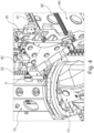
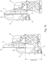
- Fig. 4 shows, by way of example, a schematic detailed view of a suspension of the machining unit of the machine tool according to the invention from Fig. 1 .
- the processing unit 10 is suspended at suspension points 11 on the suspension sections 50, for example by suspending the threaded rods 22 at the suspension points 11 on the suspension sections 50.
- the suspension of the processing unit 10 is designed with two suspension points 11 of the two suspension sections 50 lying in a horizontal plane, wherein the effective point 12 of the suspension lies exactly between the suspension points 11 of the two suspension sections 50 (see Fig. 6b ).
- the machining unit 10 is designed such that the center of gravity 101 of the entire machining unit 10 with spindle support unit 13 lies in a horizontal straight line with the effective point 12 of the suspension exactly between the suspension points 11 of the two suspension sections 50 (see also the principle according to Fig. 5 and description).
- the entire weight of the machining unit 10 with spindle support unit 13 is always evenly distributed across the two suspension points 11, from which the threaded rods 22 are suspended, regardless of the vertical Z-position of the machining unit 10.
- the vertical guide 18 of the The machining unit 10 is always relieved of load at the guide elements 32 of the support section and essentially no torques occur at this guide.
- the same torque always acts on the support section 30 via the suspension sections 50, so that the same torques always act on the horizontal guides 61 of the support section 30 on the front of the gantry section 60, regardless of the Z position of the machining unit 10, so that the position accuracy only needs to be set once (e.g. by numerical compensation in the CNC machine control), although no Z position-dependent compensation needs to be carried out, since the forces and torques acting from the support section 30 on the gantry section 60 are independent of the Z position of the machining unit 10.
- Fig. 5 shows, by way of example, a schematic detailed view of an embodiment of a machine tool 100 according to the invention with a screw drive as a gear 22 for moving the machining unit 10.
- the machining unit 10 is connected to the support section 30, for example, via a suspension 11, which is adjusted in the vertical direction via a rotatably mounted threaded rod (here, for example, as a gear 22) that can be driven by a drive 21, in such a way that the relative position of the machining unit 10 to the support section 30 can be adjusted in the vertical direction by rotating the threaded rod.
- a suspension 11 which is adjusted in the vertical direction via a rotatably mounted threaded rod (here, for example, as a gear 22) that can be driven by a drive 21, in such a way that the relative position of the machining unit 10 to the support section 30 can be adjusted in the vertical direction by rotating the threaded rod.
- a rotatably mounted threaded rod here, for example, as a gear 22
- the threaded rod follows the movement of the machining unit 10 in the vertical direction when rotating. This means that the drive 21 and gear 22 of the drive mechanism 20 are firmly connected to the machining unit 10, and the suspension 11 is firmly connected to the support section 30.
- the center of gravity 101 of the machining unit 10 is located on the threaded rod in a side view, as shown in the side view of the structure of the machine tool 100 in Fig. 5 is illustrated. If the drive mechanism 20 has only one drive 21 and one gear 22 for vertical positioning of the machining unit 10, the center of gravity 101 would essentially lie in one threaded rod, so that the entire weight of the machining unit 10 would load the threaded rod evenly and independently of the Z position in tension/compression, even if no guide 18, 32 were present. If two threaded rods are provided (see Fig.
- the effective point 12 of the suspension is exactly between the suspension points 11 and so the center of gravity 101 would essentially be between the threaded rods so that the entire weight of the Machining unit 10 applies tension/compression loads to the threaded rods evenly and independently of the Z position, even if no guide 18, 32 were present.
- the guide 18, 32 is significantly relieved of load, since during vertical movement of the machining unit 10 and in the different positions of the machining unit 10, essentially no torque is generated due to the distance of the suspension 11 (coinciding with an effective point 12 of the suspension 11) from the center of gravity 101.
- the guide 18, 32 of the machining unit 10 can be designed for considerably lighter loads and/or ensure greater guidance accuracy of the machining unit 10 over the entire guide length during the vertical positioning of the machining unit 10.
- the inventive design of the machine tool 100 effectively separates load bearing capacity from guide accuracy.
- the guide accuracy and a large portion of the load bearing capacity are provided by the corresponding guide. This can result in deformation of the guide when moving movable masses or loads along the guide if the majority of the loads must be absorbed by the guide. Because a guide can never be designed to be infinitely rigid, a compromise between guide accuracy and load bearing capacity must always be found with a conventional design.
- the machine tool 100 makes it possible to largely avoid such a compromise, since the entire load/mass of the machining unit 10 is distributed on the drive mechanism 20 (or on the threaded rod of the gear 22, as shown in Fig. 5 ), specifically in such a way that the center of gravity 101 of the machining unit 10 lies in the threaded rod. This also avoids the generation of a torque due to the distance of the suspension 11 (coinciding with the effective point 12 of the suspension 11) from the center of gravity 101, which would have to be absorbed by the guide 18, 32. As a result, the guide 18, 32 only needs to absorb significantly lower loads for the vertical positioning of the machining unit 10, which leads to a considerable improvement in the guidance accuracy over the entire length of the guide 18, 32.
- two or more drives 21 and correspondingly two or more gears 22 may be present for the vertical positioning of the processing unit 10. This would result in the point of action 12 of the suspension 11 being essentially in the middle of the corresponding distribution of the suspensions 11 (see, for example, Fig. 6b and 6c ).
- the center of gravity 101 of the processing unit 10 would then be positioned such that the center of gravity 101 of the machining unit 10 and the point of action 12 of the suspension 11 have a common vertically oriented straight line 23.
- the center of gravity 101 of the machining unit 10 can then move along this vertically oriented straight line 23 during the vertical positioning of the machining unit 10, without a significant torque arising due to a distance of the vertically oriented straight line 23 from the center of gravity 101, which would have to be absorbed by the guide 18, 32.
- the machine tool 100 can also be constructed in such a way that the drive mechanism 20 is attached to the support section 30 with at least one drive 21 and at least one gear 22, so that the suspension 11 is attached to the machining unit 10 and moves with the machining unit 10 when the machining unit 10 is vertically positioned.
- the drive mechanism 20 is attached to the support section 30 with at least one drive 21 and at least one gear 22, so that the suspension 11 is attached to the machining unit 10 and moves with the machining unit 10 when the machining unit 10 is vertically positioned.
- the drive mechanism 20 can also be designed as a combination of a rack and a gear.
- a drive 21 e.g., electric, hydraulic, or pneumatic
- the machining unit 10 has a spindle carrier 13 on which a work spindle 16 is provided.
- a clamped workpiece which is clamped, for example, on a machine table or on or in another device, can be machined according to a program for controlling the numerically controllable axes of the machine tool 100.
- the spindle carrier 13 can have a pivoting device 14, with which a pivotable section 15 of the spindle carrier 13, in which the work spindle 16 is provided, can be pivoted according to a pivot axis 17.
- the pivot axis 17 can enable the pivotable section 15 of the spindle carrier 13 to be pivoted in an angular range of +90 ° to -90 °.
- a further embodiment of the pivoting device 14 with a corresponding pivot axis 17 can be such that the pivot axis 17 is aligned at an angle of preferably 45° to the vertically oriented straight line 23 or to the spindle axis of the work spindle 16.
- the spindle axis of the work spindle 16 which is provided in the pivotable section 15 of the spindle carrier 13, can be pivoted in an angular range from 0° to 90°.
- the pivot axis 17 can be aligned such that the common center of gravity of the work spindle 16 and the pivotable section 15 of the spindle support 13 is located at the intersection point of the pivot axis 17 with the vertically oriented straight line 23. This allows the work spindle 16 to be pivoted about the pivot axis 17 without shifting the common center of gravity of the work spindle 16 and the pivotable section 15 of the spindle support 13 and thus without shifting the center of gravity (overall center of gravity) of the machining unit 10.
- the processing unit 10 is, as in the embodiment in Fig. 5 shown, guided by a guide 18, 32 with guide rails 18 of rectangular cross-section.
- the guide rails 18 are firmly connected to the processing unit 10, so that they follow a vertical positioning of the processing unit 10.
- Guide carriages 32, which are firmly connected to the support section 30, ensure safe and precise guidance of the processing unit 10 relative to the support section 30.
- the design of the guides 18, 32 can vary greatly. In addition to a rectangular cross-section of the guide rails 18, a round or triangular cross-section for the guide rails 18 can also be advantageous. However, the design options mentioned are not exhaustive; they should be understood merely as examples.
- the type of guide 18, 32 can also vary greatly.
- so-called recirculating ball bearing guides can also be used, with the recirculating ball bearings always being located in the guide carriages 32. These have the advantage of being extremely rigid and exhibiting significantly lower friction and resistance values than conventional sliding guides.
- the support section 30 can have a carriage section 31, with which the vertically guided processing unit 10 can be moved along a horizontal direction.
- the carriage section 31 can also serve as a support structure for the guide rails 18 or as a support structure for the guide carriages 32 and also have drives 21 and gears 22 both for the vertical positioning of the machining unit 10 and drives and gears for the horizontal positioning of the machining unit 10, wherein the carriage section 31 would be moved during the horizontal positioning.
- Fig. 6a shows schematically the point of action 12 of the suspension 11 when the drive mechanism 20 has a gear 22 (here a screw drive).
- the point of action 12 of the suspension 11 is located directly in the screw drive (threaded rod), so that the center of gravity 101 of the machining unit 10 is advantageously placed either directly in the point of action 12, or at least on the vertically oriented straight line 23 (in Fig. 6a not shown, see Fig. 5 ).
- the center of gravity 101 of the machining unit 10 is guided along the vertically oriented straight line 23 and thus generates either a constant or a negligibly small torque in the corresponding guides (e.g. guides 18, 32) of the machine tool 100.
- Fig. 6b shows schematically the point of action 12 of the suspension 11 when the drive mechanism 20 has two gears 22 (here two screw drives).
- the center of gravity 101 of the machining unit 10 can be guided along the vertically oriented straight line 23 and thereby generates either a constant or a negligibly small torque in the corresponding guides (e.g., guides 18, 32) of the machine tool 100.
- Fig. 6c shows schematically the point of action 12 of the suspension 11 when the drive mechanism 20 has three gears 22 (here screw drives).
- the center of gravity 101 of the machining unit 10 can advantageously be placed either directly in the point of action 12, or at least on the vertically oriented straight line 23 (in Fig. 6b not shown, see this Fig. 5 ).
- the center of gravity 101 of the machining unit 10 can again be guided along the vertically oriented straight line 23 by the vertical positioning of the machining unit 10, and here too, generates either a constant or a negligibly small torque in the corresponding guides (e.g., guides 18, 32) of the machine tool 100.
- guides e.g., guides 18, 32
- Fig. 7a shows schematically an embodiment of the machine tool 100 according to the invention with a modified arrangement of the vertical guide 18, 32.
- Fig. 7a the drive mechanism 20 with a drive 21 and a gear 22 is not shown in order to be able to see the design of the modified vertical guide 18, 32 somewhat better.
- the guide 18, 32 has been modified such that the guide carriages 32 are now attached to the machining unit 10, so that they are moved along with the vertical positioning of the machining unit 10.
- the guide rails 18 are therefore attached to the support section 30 or to the carriage section 31, respectively.
- the advantage of such a design of the guide 18, 32 is that the vertical distance of the work spindle 16 held in the spindle carrier 13 or a tool held by the work spindle 16 is always constant from the guide carriages 32, so that they function as support points in any position of the machining unit 10. If forces arise on the tool, for example, acting in a horizontal direction, the machining unit 10 behaves like a deforming structure which is firmly connected to the support section 30 or the slide section 31 by the support points (here the guide carriages 32).
- the stiffness behavior of the machining unit 10 can now be very accurately predicted, given known forces acting on the tool, for example, and given known structural conditions of the machining unit 10. Since the support points (guide carriage 32) always have the same position relative to the machining unit 10, the stiffness behavior of the machining unit 10 is constant in all vertical positions of the machining unit 10 relative to the support section 30/slide section 31, since there is no change in the distance from the work spindle 10 or the tool mounted in the work spindle 10 to the support points (guide carriage 32). This now enables very precise correction of the numerically controlled axes, regardless of the vertical positioning of the machining unit 10.
- Fig. 7b shows schematically an embodiment of the machine tool 100 according to the invention with a modified arrangement of the vertical guide 18, 32 in a side view.
- the drive mechanism 20 with a drive 21 and a gear 22 is not shown in order to be able to see the design of the modified vertical guide 18, 32 somewhat better.
- Fig. 7b the processing unit 10 is shown in two different vertical positions, wherein in the left illustration the processing unit 10 is seen in a vertically lower position and in the right illustration the processing unit 10 is seen in a vertically upper position.
Landscapes
- Engineering & Computer Science (AREA)
- Mechanical Engineering (AREA)
- Machine Tool Units (AREA)
- Turning (AREA)
- Gear Processing (AREA)
Applications Claiming Priority (1)
| Application Number | Priority Date | Filing Date | Title |
|---|---|---|---|
| DE102017216446.8A DE102017216446A1 (de) | 2017-09-17 | 2017-09-17 | Werkzeugmaschine zur Bearbeitung eines Werkstücks |
Publications (2)
| Publication Number | Publication Date |
|---|---|
| EP3456462A1 EP3456462A1 (de) | 2019-03-20 |
| EP3456462B1 true EP3456462B1 (de) | 2025-03-19 |
Family
ID=63637701
Family Applications (1)
| Application Number | Title | Priority Date | Filing Date |
|---|---|---|---|
| EP18194741.7A Active EP3456462B1 (de) | 2017-09-17 | 2018-09-17 | Werkzeugmaschine zur bearbeitung eines werkstücks |
Country Status (7)
| Country | Link |
|---|---|
| US (1) | US20190084108A1 (enExample) |
| EP (1) | EP3456462B1 (enExample) |
| JP (1) | JP7281260B2 (enExample) |
| KR (1) | KR20190032214A (enExample) |
| CN (1) | CN109514284A (enExample) |
| DE (1) | DE102017216446A1 (enExample) |
| ES (1) | ES3015550T3 (enExample) |
Families Citing this family (9)
| Publication number | Priority date | Publication date | Assignee | Title |
|---|---|---|---|---|
| US10722953B1 (en) * | 2019-01-18 | 2020-07-28 | Feng-Tien Chen | CNC milling machine combined with picking robotic arm unit |
| CA3080191A1 (en) * | 2019-05-02 | 2020-11-02 | Mark Philip Chepurny | Cnc machine, workstation and components |
| US20220023986A1 (en) * | 2019-05-02 | 2022-01-27 | Mark Cherpurny | Cnc machine, workstation and components |
| KR102058154B1 (ko) * | 2019-07-08 | 2020-02-07 | 주식회사 위멘트 | 헤드 부하 방지 기능을 갖는 머시닝센터 |
| CN112338291A (zh) * | 2020-11-24 | 2021-02-09 | 杭州芝元机电有限公司 | 一种新型齿条成型专用磨床 |
| JP7560660B2 (ja) * | 2021-04-15 | 2024-10-02 | Dmg森精機株式会社 | 工作機械 |
| EP4347178A4 (en) * | 2021-06-03 | 2025-08-20 | Mark Chepurny | CNC MACHINE, WORKSTATION AND COMPONENTS |
| KR102479173B1 (ko) * | 2021-12-21 | 2022-12-20 | 오종혁 | 공작물 가공장치 |
| CN115319488B (zh) * | 2022-09-01 | 2023-06-27 | 超同步股份有限公司 | 龙门式机床 |
Family Cites Families (45)
| Publication number | Priority date | Publication date | Assignee | Title |
|---|---|---|---|---|
| DE1112376B (de) * | 1959-10-21 | 1961-08-03 | Scharmann & Co G M B H | Horizontal-, Fraes- und Bohrwerk |
| JPH0643002B2 (ja) * | 1986-02-17 | 1994-06-08 | 株式会社森精機製作所 | Nc旋盤 |
| JPH02150134U (enExample) * | 1989-05-25 | 1990-12-25 | ||
| JPH0560748U (ja) * | 1992-01-20 | 1993-08-10 | 安田工業株式会社 | 工作機械のスピンドルヘッドの駆動装置 |
| US5575318A (en) * | 1995-02-17 | 1996-11-19 | Thermwood Corporation | Slide assembly for machine tools and method of making same |
| KR970020270A (ko) * | 1995-10-31 | 1997-05-28 | 장관순 | 드링, 탭핑 머시인 주축의 구동 제어장치 |
| JPH1015769A (ja) * | 1996-07-02 | 1998-01-20 | Hitachi Seiki Co Ltd | 主軸ヘッドの昇降駆動装置 |
| JP3683042B2 (ja) * | 1996-08-09 | 2005-08-17 | 株式会社アドバンスト・ディスプレイ | レーザー加工装置 |
| JPH1142529A (ja) * | 1997-07-25 | 1999-02-16 | Kitamura Mach Co Ltd | Nc工作機械 |
| JP3948546B2 (ja) * | 1998-08-13 | 2007-07-25 | キタムラ機械株式会社 | 工作機械 |
| JP3447982B2 (ja) * | 1999-06-16 | 2003-09-16 | 株式会社アルテクス | 超音波振動接合装置 |
| JP3357947B2 (ja) * | 2000-10-12 | 2002-12-16 | ホーコス株式会社 | 工作機械 |
| DE20019035U1 (de) * | 2000-11-08 | 2001-01-18 | Waldrich Siegen Werkzeugmaschinen GmbH, 57299 Burbach | Werkzeugmaschine, insbesondere Hochgeschwindigkeits-Bearbeitungszentrum |
| JP2002346804A (ja) * | 2001-05-17 | 2002-12-04 | Toyota Motor Corp | 旋 盤 |
| DE20115005U1 (de) * | 2001-09-11 | 2001-11-15 | Roschiwal + Partner Ingenieur GmbH Augsburg, 86179 Augsburg | Fräs- und Bohrbearbeitungszentrum |
| JP2003127044A (ja) * | 2001-10-18 | 2003-05-08 | Nsk Ltd | 直動テーブル装置 |
| JP4268842B2 (ja) * | 2003-07-15 | 2009-05-27 | 株式会社森精機製作所 | 工作機械 |
| JP4650923B2 (ja) * | 2003-09-30 | 2011-03-16 | 株式会社森精機製作所 | 工作機械 |
| JP4427689B2 (ja) * | 2004-07-08 | 2010-03-10 | オークマ株式会社 | 工作機械 |
| TWM269987U (en) * | 2005-01-07 | 2005-07-11 | Suen Cin Entpr Co Ltd | C-shaped machining center for symmetric workpiece |
| US7172375B2 (en) * | 2005-06-23 | 2007-02-06 | Mori Seiki Co., Ltd. | Machine tool |
| JP2008264891A (ja) * | 2007-04-16 | 2008-11-06 | Mori Seiki Co Ltd | ユニバーサルヘッドおよびこれを有する工作機械 |
| WO2010067651A1 (ja) * | 2008-12-09 | 2010-06-17 | 三菱電機株式会社 | 機械運動軌跡測定装置、数値制御工作機械および機械運動軌跡測定方法 |
| ATE539843T1 (de) * | 2009-06-16 | 2012-01-15 | Mag Ias Gmbh | Werkzeugmaschine zur bearbeitung von werkstücken |
| JP5025036B2 (ja) * | 2009-08-04 | 2012-09-12 | 明 杉山 | 工作機械のラム案内装置 |
| US8887361B2 (en) * | 2009-10-29 | 2014-11-18 | Dalian Kede Numerical Control Co., Ltd | Vertical turning-milling complex machining center |
| KR101726447B1 (ko) * | 2011-01-21 | 2017-04-12 | 두산공작기계 주식회사 | 고강성 복합가공기 |
| CN102962730A (zh) * | 2011-11-08 | 2013-03-13 | 杨东佐 | 数控设备 |
| CN102528090B (zh) * | 2011-12-22 | 2014-03-05 | 上海三一精机有限公司 | 一种双电机驱动四导轨支撑的车床可移动主轴箱 |
| EP2921253B1 (en) * | 2012-10-16 | 2019-06-19 | Horkos Corporation | Machine tool |
| CN103878590A (zh) * | 2012-12-19 | 2014-06-25 | 鸿准精密模具(昆山)有限公司 | 机床 |
| CN203109314U (zh) * | 2013-02-05 | 2013-08-07 | 蔡少武 | 一种带有重心切削结构的机床 |
| WO2014163483A1 (en) * | 2013-04-04 | 2014-10-09 | Universiti Malaya | An improved computer numerically controlled gantry device and method thereof |
| JP6195620B2 (ja) * | 2013-09-13 | 2017-09-13 | 株式会社牧野フライス製作所 | 工作機械 |
| CN103624614A (zh) * | 2013-12-03 | 2014-03-12 | 齐齐哈尔通联机械制造有限责任公司 | 主轴角度转换装置 |
| EP3009225A1 (en) * | 2014-10-17 | 2016-04-20 | Bostek Innovation S.L.U. | Gantry machine tool with large horizontal support crossbeam with horizontal counterbalancing device |
| TWI586463B (zh) * | 2015-01-06 | 2017-06-11 | Chen Peng-Ren | CNC double spindle drive |
| CN104723155A (zh) * | 2015-03-13 | 2015-06-24 | 宁波海天精工股份有限公司 | 四线轨滑枕双丝杠驱动系统 |
| DE102015121354A1 (de) * | 2015-12-08 | 2017-06-08 | Ms Ultraschall Technologie Gmbh | Ständermaschine |
| CN205363276U (zh) * | 2016-01-22 | 2016-07-06 | 上海铼钠克数控科技股份有限公司 | 钻铣床 |
| DE202016004618U1 (de) * | 2016-07-27 | 2016-10-18 | Detlef Görgens | Werkzeugmaschinen aus Mineralguss |
| US9757832B1 (en) * | 2016-08-11 | 2017-09-12 | Maxxtron Technology Co., Ltd. | Sliding seat device with surrounding structure |
| DE202016105545U1 (de) * | 2016-10-06 | 2017-01-23 | Goodway Machine Corp. | Werkzeugmaschine mit Spindelpositioniervorrichtung |
| JP6779319B2 (ja) * | 2017-02-07 | 2020-11-04 | 株式会社牧野フライス製作所 | 工作機械 |
| US10293442B2 (en) * | 2017-07-07 | 2019-05-21 | Baizheng Innovation Technology Co., Ltd. | C-type CNC machine center |
-
2017
- 2017-09-17 DE DE102017216446.8A patent/DE102017216446A1/de active Pending
-
2018
- 2018-09-13 JP JP2018171274A patent/JP7281260B2/ja active Active
- 2018-09-14 KR KR1020180110215A patent/KR20190032214A/ko not_active Withdrawn
- 2018-09-14 US US16/131,888 patent/US20190084108A1/en not_active Abandoned
- 2018-09-17 ES ES18194741T patent/ES3015550T3/es active Active
- 2018-09-17 CN CN201811080843.1A patent/CN109514284A/zh active Pending
- 2018-09-17 EP EP18194741.7A patent/EP3456462B1/de active Active
Also Published As
| Publication number | Publication date |
|---|---|
| JP2019077025A (ja) | 2019-05-23 |
| EP3456462A1 (de) | 2019-03-20 |
| JP7281260B2 (ja) | 2023-05-25 |
| KR20190032214A (ko) | 2019-03-27 |
| US20190084108A1 (en) | 2019-03-21 |
| DE102017216446A1 (de) | 2019-03-21 |
| ES3015550T3 (en) | 2025-05-06 |
| CN109514284A (zh) | 2019-03-26 |
Similar Documents
| Publication | Publication Date | Title |
|---|---|---|
| EP3456462B1 (de) | Werkzeugmaschine zur bearbeitung eines werkstücks | |
| AT506486B1 (de) | Aufspannvorrichtung für eine rechnergesteuerte, spanabhebende bearbeitungsmaschine | |
| DE3005606C2 (de) | Numerisch gesteuerte Maschine zum Schleifen mehrerer unterschiedlicher Flächen an ein- und demselben Werkstück | |
| EP2732895B1 (de) | Werkzeugmaschine zur Herstellung von Profilen | |
| DE10141865A1 (de) | Universal-Fräs- und Bohrmaschine | |
| DE102007009843A1 (de) | Verfahren zur Schleifbearbeitung eines Maschinenbauteils und Schleifmaschine zur Durchführung des Verfahrens | |
| EP0812652A1 (de) | Vorrichtung zur Bearbeitung und/oder Montage von Werkstücken | |
| WO1999032256A1 (de) | Werkzeugmaschine zum bearbeiten von länglichen werkstücken | |
| DE10116994A1 (de) | Werkzeugmaschine | |
| EP3999273A1 (de) | Werkzeugmaschine und verfahren für die wälzbearbeitung von rotationsteilen mit nutförmigen profilen | |
| DE1602883A1 (de) | Drehbank mit mehreren Werkzeugen | |
| EP1080834A2 (de) | Schleifmaschinen zum spitzenlosen Schleifen von Werkstücken | |
| DE2514918A1 (de) | Drehbank zur bearbeitung von hohlkoerpern | |
| DE102011117819B4 (de) | Spitzenlose Rundschleifmaschine | |
| EP1025953B1 (de) | Werkzeugmaschine | |
| DE4123045A1 (de) | Gewindeschleifmaschine mit einer auf einem schleiftisch angeordneten schleifeinheit fuer profilerzeugende schleifoperationen | |
| EP1832383B1 (de) | Werkzeugmaschine | |
| EP1112806A2 (de) | Werkzeugmaschine mit einer in mindestens einer Arbeitsebene bewegbaren und positionierbaren Werkzeugspindel | |
| CH692382A5 (de) | Profilrollmaschine mit Kraftrahmen. | |
| DE3933863A1 (de) | Schleifmaschine | |
| DE2105667A1 (de) | Werkzeugmaschine | |
| DE102005061613A1 (de) | Werkzeugmaschine zum Bearbeiten von Verzahnungen | |
| DE102022134502C5 (de) | Schwenkbiegemaschine | |
| DE102015121280A1 (de) | Verfahren und Vorrichtung zur Bearbeitung von rotierbaren Werkstücken | |
| EP2419240A2 (de) | Drehmaschine mit mehrfachem werkzeugträger |
Legal Events
| Date | Code | Title | Description |
|---|---|---|---|
| PUAI | Public reference made under article 153(3) epc to a published international application that has entered the european phase |
Free format text: ORIGINAL CODE: 0009012 |
|
| STAA | Information on the status of an ep patent application or granted ep patent |
Free format text: STATUS: THE APPLICATION HAS BEEN PUBLISHED |
|
| AK | Designated contracting states |
Kind code of ref document: A1 Designated state(s): AL AT BE BG CH CY CZ DE DK EE ES FI FR GB GR HR HU IE IS IT LI LT LU LV MC MK MT NL NO PL PT RO RS SE SI SK SM TR |
|
| AX | Request for extension of the european patent |
Extension state: BA ME |
|
| STAA | Information on the status of an ep patent application or granted ep patent |
Free format text: STATUS: REQUEST FOR EXAMINATION WAS MADE |
|
| 17P | Request for examination filed |
Effective date: 20190920 |
|
| RBV | Designated contracting states (corrected) |
Designated state(s): AL AT BE BG CH CY CZ DE DK EE ES FI FR GB GR HR HU IE IS IT LI LT LU LV MC MK MT NL NO PL PT RO RS SE SI SK SM TR |
|
| STAA | Information on the status of an ep patent application or granted ep patent |
Free format text: STATUS: EXAMINATION IS IN PROGRESS |
|
| 17Q | First examination report despatched |
Effective date: 20220608 |
|
| GRAP | Despatch of communication of intention to grant a patent |
Free format text: ORIGINAL CODE: EPIDOSNIGR1 |
|
| STAA | Information on the status of an ep patent application or granted ep patent |
Free format text: STATUS: GRANT OF PATENT IS INTENDED |
|
| INTG | Intention to grant announced |
Effective date: 20231019 |
|
| GRAJ | Information related to disapproval of communication of intention to grant by the applicant or resumption of examination proceedings by the epo deleted |
Free format text: ORIGINAL CODE: EPIDOSDIGR1 |
|
| STAA | Information on the status of an ep patent application or granted ep patent |
Free format text: STATUS: EXAMINATION IS IN PROGRESS |
|
| INTC | Intention to grant announced (deleted) | ||
| RAP3 | Party data changed (applicant data changed or rights of an application transferred) |
Owner name: DMG MORI SEEBACH GMBH |
|
| GRAP | Despatch of communication of intention to grant a patent |
Free format text: ORIGINAL CODE: EPIDOSNIGR1 |
|
| STAA | Information on the status of an ep patent application or granted ep patent |
Free format text: STATUS: GRANT OF PATENT IS INTENDED |
|
| GRAS | Grant fee paid |
Free format text: ORIGINAL CODE: EPIDOSNIGR3 |
|
| INTG | Intention to grant announced |
Effective date: 20250114 |
|
| GRAA | (expected) grant |
Free format text: ORIGINAL CODE: 0009210 |
|
| STAA | Information on the status of an ep patent application or granted ep patent |
Free format text: STATUS: THE PATENT HAS BEEN GRANTED |
|
| AK | Designated contracting states |
Kind code of ref document: B1 Designated state(s): AL AT BE BG CH CY CZ DE DK EE ES FI FR GB GR HR HU IE IS IT LI LT LU LV MC MK MT NL NO PL PT RO RS SE SI SK SM TR |
|
| REG | Reference to a national code |
Ref country code: GB Ref legal event code: FG4D Free format text: NOT ENGLISH |
|
| REG | Reference to a national code |
Ref country code: CH Ref legal event code: EP |
|
| REG | Reference to a national code |
Ref country code: IE Ref legal event code: FG4D Free format text: LANGUAGE OF EP DOCUMENT: GERMAN |
|
| REG | Reference to a national code |
Ref country code: DE Ref legal event code: R096 Ref document number: 502018015657 Country of ref document: DE |
|
| REG | Reference to a national code |
Ref country code: ES Ref legal event code: FG2A Ref document number: 3015550 Country of ref document: ES Kind code of ref document: T3 Effective date: 20250506 |
|
| PG25 | Lapsed in a contracting state [announced via postgrant information from national office to epo] |
Ref country code: RS Free format text: LAPSE BECAUSE OF FAILURE TO SUBMIT A TRANSLATION OF THE DESCRIPTION OR TO PAY THE FEE WITHIN THE PRESCRIBED TIME-LIMIT Effective date: 20250619 |
|
| PG25 | Lapsed in a contracting state [announced via postgrant information from national office to epo] |
Ref country code: FI Free format text: LAPSE BECAUSE OF FAILURE TO SUBMIT A TRANSLATION OF THE DESCRIPTION OR TO PAY THE FEE WITHIN THE PRESCRIBED TIME-LIMIT Effective date: 20250319 |
|
| REG | Reference to a national code |
Ref country code: LT Ref legal event code: MG9D |
|
| PG25 | Lapsed in a contracting state [announced via postgrant information from national office to epo] |
Ref country code: NO Free format text: LAPSE BECAUSE OF FAILURE TO SUBMIT A TRANSLATION OF THE DESCRIPTION OR TO PAY THE FEE WITHIN THE PRESCRIBED TIME-LIMIT Effective date: 20250619 |
|
| PG25 | Lapsed in a contracting state [announced via postgrant information from national office to epo] |
Ref country code: HR Free format text: LAPSE BECAUSE OF FAILURE TO SUBMIT A TRANSLATION OF THE DESCRIPTION OR TO PAY THE FEE WITHIN THE PRESCRIBED TIME-LIMIT Effective date: 20250319 |
|
| PG25 | Lapsed in a contracting state [announced via postgrant information from national office to epo] |
Ref country code: LV Free format text: LAPSE BECAUSE OF FAILURE TO SUBMIT A TRANSLATION OF THE DESCRIPTION OR TO PAY THE FEE WITHIN THE PRESCRIBED TIME-LIMIT Effective date: 20250319 |
|
| PG25 | Lapsed in a contracting state [announced via postgrant information from national office to epo] |
Ref country code: GR Free format text: LAPSE BECAUSE OF FAILURE TO SUBMIT A TRANSLATION OF THE DESCRIPTION OR TO PAY THE FEE WITHIN THE PRESCRIBED TIME-LIMIT Effective date: 20250620 Ref country code: BG Free format text: LAPSE BECAUSE OF FAILURE TO SUBMIT A TRANSLATION OF THE DESCRIPTION OR TO PAY THE FEE WITHIN THE PRESCRIBED TIME-LIMIT Effective date: 20250319 |
|
| REG | Reference to a national code |
Ref country code: NL Ref legal event code: MP Effective date: 20250319 |
|
| PG25 | Lapsed in a contracting state [announced via postgrant information from national office to epo] |
Ref country code: NL Free format text: LAPSE BECAUSE OF FAILURE TO SUBMIT A TRANSLATION OF THE DESCRIPTION OR TO PAY THE FEE WITHIN THE PRESCRIBED TIME-LIMIT Effective date: 20250319 |
|
| PG25 | Lapsed in a contracting state [announced via postgrant information from national office to epo] |
Ref country code: SE Free format text: LAPSE BECAUSE OF FAILURE TO SUBMIT A TRANSLATION OF THE DESCRIPTION OR TO PAY THE FEE WITHIN THE PRESCRIBED TIME-LIMIT Effective date: 20250319 |
|
| REG | Reference to a national code |
Ref country code: CH Ref legal event code: U11 Free format text: ST27 STATUS EVENT CODE: U-0-0-U10-U11 (AS PROVIDED BY THE NATIONAL OFFICE) Effective date: 20251001 |
|
| PG25 | Lapsed in a contracting state [announced via postgrant information from national office to epo] |
Ref country code: SM Free format text: LAPSE BECAUSE OF FAILURE TO SUBMIT A TRANSLATION OF THE DESCRIPTION OR TO PAY THE FEE WITHIN THE PRESCRIBED TIME-LIMIT Effective date: 20250319 |
|
| PG25 | Lapsed in a contracting state [announced via postgrant information from national office to epo] |
Ref country code: PT Free format text: LAPSE BECAUSE OF FAILURE TO SUBMIT A TRANSLATION OF THE DESCRIPTION OR TO PAY THE FEE WITHIN THE PRESCRIBED TIME-LIMIT Effective date: 20250721 |
|
| PGFP | Annual fee paid to national office [announced via postgrant information from national office to epo] |
Ref country code: DE Payment date: 20250930 Year of fee payment: 8 |
|
| PG25 | Lapsed in a contracting state [announced via postgrant information from national office to epo] |
Ref country code: PL Free format text: LAPSE BECAUSE OF FAILURE TO SUBMIT A TRANSLATION OF THE DESCRIPTION OR TO PAY THE FEE WITHIN THE PRESCRIBED TIME-LIMIT Effective date: 20250319 |
|
| PGFP | Annual fee paid to national office [announced via postgrant information from national office to epo] |
Ref country code: GB Payment date: 20250923 Year of fee payment: 8 |
|
| PGFP | Annual fee paid to national office [announced via postgrant information from national office to epo] |
Ref country code: FR Payment date: 20250924 Year of fee payment: 8 |
|
| PG25 | Lapsed in a contracting state [announced via postgrant information from national office to epo] |
Ref country code: CZ Free format text: LAPSE BECAUSE OF FAILURE TO SUBMIT A TRANSLATION OF THE DESCRIPTION OR TO PAY THE FEE WITHIN THE PRESCRIBED TIME-LIMIT Effective date: 20250319 Ref country code: EE Free format text: LAPSE BECAUSE OF FAILURE TO SUBMIT A TRANSLATION OF THE DESCRIPTION OR TO PAY THE FEE WITHIN THE PRESCRIBED TIME-LIMIT Effective date: 20250319 |
|
| PG25 | Lapsed in a contracting state [announced via postgrant information from national office to epo] |
Ref country code: RO Free format text: LAPSE BECAUSE OF FAILURE TO SUBMIT A TRANSLATION OF THE DESCRIPTION OR TO PAY THE FEE WITHIN THE PRESCRIBED TIME-LIMIT Effective date: 20250319 |
|
| PG25 | Lapsed in a contracting state [announced via postgrant information from national office to epo] |
Ref country code: SK Free format text: LAPSE BECAUSE OF FAILURE TO SUBMIT A TRANSLATION OF THE DESCRIPTION OR TO PAY THE FEE WITHIN THE PRESCRIBED TIME-LIMIT Effective date: 20250319 |
|
| PG25 | Lapsed in a contracting state [announced via postgrant information from national office to epo] |
Ref country code: IS Free format text: LAPSE BECAUSE OF FAILURE TO SUBMIT A TRANSLATION OF THE DESCRIPTION OR TO PAY THE FEE WITHIN THE PRESCRIBED TIME-LIMIT Effective date: 20250719 |