EP3453540A1 - Radschale zur aufnahme eines rads eines zweirads sowie trägerprofilanordnung einer zweiradträgereinheit mit einem trägerprofil und mit einer derartigen radschale - Google Patents
Radschale zur aufnahme eines rads eines zweirads sowie trägerprofilanordnung einer zweiradträgereinheit mit einem trägerprofil und mit einer derartigen radschale Download PDFInfo
- Publication number
- EP3453540A1 EP3453540A1 EP18185674.1A EP18185674A EP3453540A1 EP 3453540 A1 EP3453540 A1 EP 3453540A1 EP 18185674 A EP18185674 A EP 18185674A EP 3453540 A1 EP3453540 A1 EP 3453540A1
- Authority
- EP
- European Patent Office
- Prior art keywords
- wheel
- wheel shell
- securing
- securing leg
- tensioning
- Prior art date
- Legal status (The legal status is an assumption and is not a legal conclusion. Google has not performed a legal analysis and makes no representation as to the accuracy of the status listed.)
- Granted
Links
Images


Classifications
-
- B—PERFORMING OPERATIONS; TRANSPORTING
- B60—VEHICLES IN GENERAL
- B60B—VEHICLE WHEELS; CASTORS; AXLES FOR WHEELS OR CASTORS; INCREASING WHEEL ADHESION
- B60B30/00—Means for holding wheels or parts thereof
- B60B30/06—Means for holding wheels or parts thereof engaging the wheel body, e.g. the rim
-
- B—PERFORMING OPERATIONS; TRANSPORTING
- B60—VEHICLES IN GENERAL
- B60R—VEHICLES, VEHICLE FITTINGS, OR VEHICLE PARTS, NOT OTHERWISE PROVIDED FOR
- B60R9/00—Supplementary fittings on vehicle exterior for carrying loads, e.g. luggage, sports gear or the like
- B60R9/08—Supplementary fittings on vehicle exterior for carrying loads, e.g. luggage, sports gear or the like specially adapted for sports gear
- B60R9/10—Supplementary fittings on vehicle exterior for carrying loads, e.g. luggage, sports gear or the like specially adapted for sports gear for cycles
-
- B—PERFORMING OPERATIONS; TRANSPORTING
- B60—VEHICLES IN GENERAL
- B60B—VEHICLE WHEELS; CASTORS; AXLES FOR WHEELS OR CASTORS; INCREASING WHEEL ADHESION
- B60B1/00—Spoked wheels; Spokes thereof
- B60B1/003—Spoked wheels; Spokes thereof specially adapted for bicycles
Definitions
- the invention relates to a wheel shell for receiving a wheel of a bicycle, in particular a bicycle, with a Radschalenanalysis which is held in the assembled state on a support profile of a two-wheel carrier unit, wherein the Radschalenanalysis a flexible strap and a tensioning and locking lock are assigned for the strap.
- the invention also relates to a carrier profile arrangement of a two-wheel carrier unit with a carrier profile and with such a wheel shell.
- the DE 10 2010 015 652 B4 discloses a wheel shell for a bicycle carrier which is fixable on a carrier profile.
- the wheel shell has a one-piece wheel shell body made of plastic, on whose one outer edge an end portion of a flexible support band is attached, and on the opposite outer edge of a tensioning and locking lock is attached.
- the Radschalen endeavor protrudes from the carrier profile upwards.
- the strap is passed over a rim ring between the spokes of the wheel and inserted into the tensioning and locking lock. By manual clamping movements, the strap is lashed to the rim ring and thus inevitably pulls a tire rolling surface of the wheel against a support region of the Radschalen emotionss.
- the object of the invention is to provide a wheel shell and a carrier profile arrangement of the type mentioned, which allow a simplified assembly and disassembly of a wheel.
- the clamping band is held at one end to a securing leg, which is mounted relative to the Radschalen endeavor laterally adjacent to a receiving area for the wheel about a pivot axis pivotally extending in the longitudinal direction of the Radschalen emotionss that the securing leg can be pivoted between a release position protruding away from the receiving area and a securing position projecting towards the receiving area.
- the securing leg is folded down, the wheel can be relatively flat brought from a side over the Radschalen endeavor during assembly or disassembly.
- the wheel is inserted from above into a corresponding receiving area.
- the solution according to the invention is particularly advantageously suitable for wheel shells which are used in carrier profiles of bicycle carriers.
- solution according to the invention can also be used for motorcycle carriers.
- the wheel shell body is made of plastic.
- the securing leg, which is mounted pivotably relative to the Radschalenanalysis is made of plastic.
- the wheel well and a corresponding carrier profile can be used both in bicycle rear carriers and bicycle roof carriers, which are rear or roof mounted on motor vehicles.
- the tensioning and locking lock is arranged on a side region of the Radschalen emotionss, which is provided opposite to the securing leg, on which the clamping band is held at the end.
- the tensioning strap can be guided by the one pivotable securing leg over a cross section of a wheel of a two-wheeled vehicle and inserted opposite into the tensioning and locking lock and preferably manually tensioned and fixed.
- the tensioning and locking lock is held on a further securing leg, which is mounted pivotably on the side region of the Radschalen emotionss about a pivot axis which is extended in the longitudinal direction of the Radschalen emotionss that the securing leg between a projecting away from the receiving area release position and a securing position projecting towards the receiving area can be pivoted.
- a total of two pivotable securing legs are provided on opposite side portions of the Radschalen emotionss, wherein a first pivotable securing leg holds the strap and the second pivotable securing leg holds the tensioning and locking lock and carries.
- the securing leg is provided on an inner side facing the receiving area with supporting profiles, which are supported on the wheel when the wheel is received. If the wheel shell is provided with two opposite securing legs, both securing legs are provided in the region of their inside with corresponding support profiles.
- the support profiles serve to increase a static friction between flanks of a tire casing of the wheel and the securing legs, when the locking legs are in their securing position and the strap is lashed. By lashing the tension band after the connection with the tensioning and locking lock, the locking legs are inevitably pressed inwards against the tire of the wheel.
- the profilings are transverse to the pivot axis of the securing leg.
- the profiles also run transversely to the circumferential direction of the tire of the wheel, so that the profilings are in the flanks of the tire casing impress and in addition to a corresponding frictional connection in the circumferential direction of the tire can also cause a limited positive engagement.
- the locking and retaining force exerted by the securing legs on the tire of the wheel is thereby increased.
- the clamping band is fastened with a front end by means of at least one mechanical fastening element to the securing leg.
- the strap is held by means of a Befest Trentsniets on the securing leg.
- a corresponding rivet connection is simple and inexpensive to produce and provides a secure attachment of the clamping band on the securing leg.
- the tensioning and locking lock is fastened to the securing leg by means of at least one mechanical fastening element.
- the tensioning and locking lock is held by means of only a single Befest Trentsniets on the securing leg.
- it is alternatively provided to secure the tensioning band and / or tensioning and locking lock by means of a plurality of fastening elements on the respective securing leg, wherein the fastening elements can also be configured as screw or pin connections or the like.
- the clamping band and / or the tensioning and locking lock are each arranged on the outside of the respective securing leg. This facilitates on the one hand the mounting of the clamping band and the tensioning and locking lock on the respective securing leg. On the other hand, the arrangement of the respective securing leg in its fixing position on the wheel is not adversely affected by the tensioning band and / or the tensioning and locking lock by the outside arrangement of the tensioning band and / or the tensioning and locking lock.
- the object underlying the invention is achieved in that the Radschalen endeavor is slidably mounted on the carrier profile, and that the carrier profile is provided on opposite sides with guide profiles in the complementary Guide profiles of the Radschalen emotionss engage such that the mutually complementary guide profiles are clamped positively against each other in a fixation of the clamping band to a wheel cross section of a recorded wheel.
- an additional fixing device for the slidable Radschalen endeavor is dispensable. Because by tightening and fixing the tension band and the tensioning and locking lock on a corresponding wheel cross section of the wheel shell body is necessarily clamped relative to the carrier profile. This facilitates assembly and disassembly a wheel as well as a displacement and positioning of the Radschalen emotionss relative to the carrier profile.
- a two-wheel carrier in the form of a bicycle carrier has according to the Fig. 1a to 4 a carrier profile 2, which is made of metal, in this case made of a light metal alloy.
- the carrier profile 2 is fixed in the mounted state on a support structure of the bicycle carrier.
- the bicycle carrier itself is carried out in the assembled state either as a rear carrier or as a roof rack and mounted in a roof area or a rear area of a motor vehicle.
- the carrier profile 2 is designed as a hollow profile, which is provided in the region of its upper side with a gutter or wedge shape, as the Fig. 1a and 1b good to see. In the area of an underside retaining grooves are provided, by means of which the carrier profile 2 can be fixed on the support structure of the bicycle carrier.
- the carrier profile 2 and the wheel shell 3 form a carrier profile arrangement in the context of the invention.
- a wheel shell 3 Arranged on the carrier profile 2 is a wheel shell 3 which serves to fix a wheel 1 of a bicycle.
- the wheel 1 has a tire and a rim 4, which is provided with wire spokes 5.
- the wheel shell 3 has a wheel shell body 8, which is designed as a plastic component.
- the wheel shell body 8 has in the region of its top a wedge-like receiving area A, which is designed as a frame shape with an inner circumferential edge 18, such as Fig. 4 can be seen.
- Within the frame shape of the receiving area A to the top of the carrier profile 2 is open.
- the frame shape is matched to the wedge or trough shape of the top of the carrier profile 2, so that the frame shape of the receiving area A of the Radschalen body 8 rests with its underside largely flat on a surface of the top of the support section 2.
- the wedge or trough shape of the receiving area A of the Radschalen stresses 8 forms in the region of a center of the upper side of the support section 2 an unspecified buckling or folding, which is dimensionally stable and directed downwards and immersed in a middle trough the top of the support section 2.
- the wheel shell body 8 also has on its opposite side regions downwardly projecting side legs, which terminate in serving as a guide profiles guide webs 14.
- the guide webs 14 are curved inwards and upwards, so that the guide webs 14, which form the free end regions of the side limbs, project upwards parallel to one another.
- the guide webs 14 dive in as complementary guide profiling serving guide grooves 13 of the support section 2, which are provided at lower side portions of the support section 2 and open at the bottom.
- the downwardly facing guide grooves 13 of the carrier profile 2 have a substantially rectangular cross-section.
- the upwardly into the guide grooves 13 dipping guide webs 14 of the side portions of the Radschalen stressess 8 are designed to be complementary rectangular in cross-section to be slidably mounted in the guide grooves 13 in the longitudinal direction of the support section 2.
- the wheel shell body 8 has at the level of the opposite outer edges of the carrier profile 2 and thus in the region of an upper side of the respective side region of the Radschalenitiess 8 each have a securing leg 9, 11 which is mounted by means of a pivot bearing about a pivot axis 10, 12 pivotally mounted on the Radschalen endeavor 8.
- the two pivot axes 12 extend parallel to each other and parallel to a central longitudinal axis of the carrier profile 2 and thus also in the longitudinal direction of the Radschalen emotionss 8.
- the respective hinge assembly for the respective securing leg 9 is by on Radschalenanalysis 8 on the one hand and the respective securing leg 9, 11 on the other hand integrally molded hinge sleeve sections formed by each serving as a pivot axis 10, 12 serving Plug pin is inserted through.
- the two securing legs 9, 11 on opposite sides of the Radschalen emotionss 8 are designed identical to each other.
- Both securing legs 9, 11 have on their inner side supporting profiles 15, which are at least largely aligned transversely to the longitudinal extent of the respective pivot axis 10, 12 and designed as projecting from a surface of the inside of the respective securing leg 11 projecting and parallel aligned support webs.
- the support profiles 15 are integrally formed on the respective securing leg 9, 11.
- the support profiles 15 serve to press in the fixed state of the wheel 1 against the side edges of the tire of the wheel 1 and thus to increase the retention force for the wheel 1.
- a flexible strap 6 is attached at the one securing leg 11.
- a tensioning and locking lock 7 is attached at the other securing leg 9, i. on the opposite side of the Radschalen stresses 8, a tensioning and locking lock 7 is attached.
- the tension band 6 is designed as a snap band and positioned with an end portion on an outer side of the securing leg 11 and by means of a Befest Trentsniets 16, i. a mechanical fastener, held on the securing leg 11. The remaining part of the tension band 6 protrudes freely from the securing leg 11.
- the tensioning and locking lock 7 is fastened by means of a Befest Trentsniets 17 on an outer side of the securing leg 9.
- the tensioning and locking lock 7 has a tensioning lever and a detent pawl arrangement, wherein the tensioning lever is manually operable.
- the two securing legs 9 and 11 are pivoted outwardly into their release position and the flexible strap 6 is free from the one locking leg 11, starting to the side or down.
- the wheel 1 is inserted into the receiving area A, wherein a running surface of the tire casing of the wheel 1 is supported directly on the surface of the carrier profile 2 in the bounded by the edge region 18 portion of the frame shape of the Radschalen stressess 8.
- the two securing legs 11 and 9 are pivoted upward until the support profiles 15 of the two securing legs 9, 11 abut against opposite side edges of the tire casing of the wheel 1.
- the tension band 6 is passed through the wheel spokes 5 of the wheel 1 and engages over the rim 4.
- the tension band 6 is in the tensioning and Locking 7 pushed into it and then stretched by the clamping lever until the clamping band 6 is firmly pulled against the rim 4.
- the support profiles 15 of the securing legs 11 and 9 inevitably press against the side flanks of the tire casing.
- the securing legs 9 and 11 are pulled due to the tension caused by the tension of the tension band 6 inevitably upwards.
- the tension band 6 is pulled out of the tensioning and locking lock 7 upwards in a simple manner after loosening the tensioning and locking lock 7, the two securing legs 9 and 11 are opened, if they are not Already by their own weight swing outwards and downwards, and the wheel 1 can be removed.
Landscapes
- Engineering & Computer Science (AREA)
- Mechanical Engineering (AREA)
- Fittings On The Vehicle Exterior For Carrying Loads, And Devices For Holding Or Mounting Articles (AREA)
- Handcart (AREA)
Abstract
Description
- Die Erfindung betrifft eine Radschale zur Aufnahme eines Rads eines Zweirads, insbesondere eines Fahrrads, mit einem Radschalenkörper, der in montiertem Zustand auf einem Trägerprofil einer Zweiradträgereinheit gehalten ist, wobei dem Radschalenkörper ein flexibles Spannband sowie ein Spann- und Arretierschloss für das Spannband zugeordnet sind. Die Erfindung betrifft zudem eine Trägerprofilanordnung einer Zweiradträgereinheit mit einem Trägerprofil und mit einer derartigen Radschale.
- Die
DE 10 2010 015 652 B4 offenbart eine Radschale für einen Fahrradträger, die auf einem Trägerprofil fixierbar ist. Die Radschale weist einen aus Kunststoff hergestellten, einteiligen Radschalenkörper auf, an dessen einer Außenflanke ein Endbereich eines flexiblen Stützbands befestigt ist, und an dessen gegenüberliegender Außenflanke ein Spann- und Arretierschloss befestigt ist. Der Radschalenkörper ragt von dem Trägerprofil aus nach oben ab. Zur Fixierung eines Rads eines Fahrrads wird das Spannband oberhalb eines Felgenrings zwischen Speichen des Rads hindurchgeführt und in das Spann- und Arretierschloss eingesteckt. Durch manuelle Spannbewegungen wird das Spannband auf dem Felgenring festgezurrt und zieht so zwangsläufig eine Reifenabrollfläche des Rads gegen einen Stützbereich des Radschalenkörpers. - Aufgabe der Erfindung ist es, eine Radschale und eine Trägerprofilanordnung der eingangs genannten Art zu schaffen, die eine vereinfachte Montage und Demontage eines Rads ermöglichen.
- Diese Aufgabe wird für die Radschale dadurch gelöst, dass das Spannband einends an einem Sicherungsschenkel gehalten ist, der relativ zu dem Radschalenkörper seitlich neben einem Aufnahmebereich für das Rad um eine Schwenkachse schwenkbeweglich gelagert ist, die derart in Längsrichtung des Radschalenkörpers erstreckt ist, dass der Sicherungsschenkel zwischen einer von dem Aufnahmebereich weg ragenden Freigabestellung und einer zu dem Aufnahmebereich hin ragenden Sicherungsstellung verschwenkbar ist. Dadurch, dass der Sicherungsschenkel umklappbar ist, kann das Rad bei einer Montage oder Demontage relativ flach von einer Seite her über den Radschalenkörper gebracht werden. Somit ist ein Einsetzen des Rads in den Aufnahmebereich des Radschalenkörpers von einer Seite her möglich. Beim Stand der Technik hingegen wird das Rad von oben her in einen entsprechenden Aufnahmebereich eingesetzt. Die erfindungsgemäße Lösung eignet sich in besonders vorteilhafter Weise für Radschalen, die bei Trägerprofilen von Fahrradträgern eingesetzt werden. In gleicher Weise ist die erfindungsgemäße Lösung jedoch auch für Motorradträger einsetzbar. Der Radschalenkörper ist aus Kunststoff hergestellt. Auch der Sicherungsschenkel, der relativ zu dem Radschalenkörper schwenkbeweglich gelagert ist, ist aus Kunststoff hergestellt. Die Radschale und ein entsprechendes Trägerprofil sind sowohl bei Fahrradheckträgern als auch bei Fahrraddachträgern einsetzbar, die heck- oder dachseitig an Kraftfahrzeugen montiert werden.
- In Ausgestaltung der Erfindung ist das Spann- und Arretierschloss an einem Seitenbereich des Radschalenkörpers angeordnet, der gegenüberliegend zu dem Sicherungsschenkel vorgesehen ist, an dem das Spannband endseitig gehalten ist. Dadurch kann das Spannband von dem einen schwenkbeweglichen Sicherungsschenkel aus über einen Querschnitt eines Rads eines Zweirads geführt und gegenüberliegend in das Spann- und Arretierschloss eingeführt und vorzugsweise manuell gespannt und fixiert werden.
- In weiterer Ausgestaltung der Erfindung ist das Spann- und Arretierschloss an einem weiteren Sicherungsschenkel gehalten, der an dem Seitenbereich des Radschalenkörpers um eine Schwenkachse schwenkbeweglich gelagert ist, die derart in Längsrichtung des Radschalenkörpers erstreckt ist, dass der Sicherungsschenkel zwischen einer von dem Aufnahmebereich weg ragenden Freigabestellung und einer zu dem Aufnahmebereich hin ragenden Sicherungsstellung verschwenkbar ist. Gemäß dieser Ausgestaltung sind an gegenüberliegenden Seitenbereichen des Radschalenkörpers insgesamt zwei schwenkbewegliche Sicherungsschenkel vorgesehen, wobei ein erster schwenkbeweglicher Sicherungsschenkel das Spannband und der zweite schwenkbewegliche Sicherungsschenkel das Spann- und Arretierschloss hält und trägt.
- In weiterer Ausgestaltung der Erfindung ist der Sicherungsschenkel an einer dem Aufnahmebereich zugewandten Innenseite mit Stützprofilierungen versehen, die sich bei aufgenommenem Rad an dem Rad abstützen. Wenn die Radschale mit zwei gegenüberliegenden Sicherungsschenkeln versehen ist, sind beide Sicherungsschenkel im Bereich ihrer Innenseite mit entsprechenden Stützprofilierungen versehen. Die Stützprofilierungen dienen dazu, eine Haftreibung zwischen Flanken eines Reifenmantels des Rads und den Sicherungsschenkeln zu erhöhen, wenn die Sicherungsschenkel sich in ihrer Sicherungsstellung befinden und das Spannband festgezurrt ist. Durch das Festzurren des Spannbands nach der Verbindung mit dem Spann- und Arretierschloss werden die Sicherungsschenkel zwangsläufig nach innen gegen den Reifen des Rads gepresst.
- In weiterer Ausgestaltung der Erfindung sind die Profilierungen quer zur Schwenkachse des Sicherungsschenkels erstreckt. Damit verlaufen die Profilierungen auch quer zur Umfangsrichtung des Reifens des Rads, so dass die Profilierungen sich in die Flanken des Reifenmantels eindrücken und zusätzlich zu einem entsprechenden Kraftschluss in Umfangsrichtung des Reifens auch noch einen begrenzten Formschluss bewirken können. Die Sicherungs- und Rückhaltekraft, die die Sicherungsschenkel auf den Reifen des Rads ausübt, wird hierdurch erhöht.
- In weiterer Ausgestaltung der Erfindung ist das Spannband mit einem Stirnende mittels wenigstens eines mechanischen Befestigungselements an dem Sicherungsschenkel befestigt. Vorzugsweise ist das Spannband mittels eines Befestigungsniets an dem Sicherungsschenkel gehalten. Eine entsprechende Nietverbindung ist einfach und kostengünstig herstellbar und bietet eine sichere Befestigung des Spannbands am Sicherungsschenkel.
- In weiterer Ausgestaltung der Erfindung ist das Spann- und Arretierschloss mittels wenigstens eines mechanischen Befestigungselements an dem Sicherungsschenkel befestigt. Vorzugsweise ist auch das Spann- und Arretierschloss mittels lediglich eines einzelnen Befestigungsniets an dem Sicherungsschenkel gehalten. Für beide Ausgestaltungen ist alternativ vorgesehen, das Spannband und/oder Spann- und Arretierschloss mittels mehrerer Befestigungselemente an dem jeweiligen Sicherungsschenkel zu sichern, wobei die Befestigungselemente auch als Schraub- oder Stiftverbindungen oder Ähnliches ausgestaltet sein können.
- In weiterer Ausgestaltung der Erfindung sind das Spannband und/oder das Spann- und Arretierschloss jeweils außenseitig an dem jeweiligen Sicherungsschenkel angeordnet. Dies erleichtert zum einen die Montage des Spannbands und des Spann- und Arretierschlosses an dem jeweiligen Sicherungsschenkel. Zum anderen wird durch die außenseitige Anordnung des Spannbands und/oder des Spann- und Arretierschlosses die Anlage des jeweiligen Sicherungsschenkels in seiner Fixierstellung am Rad nicht durch das Spannband und/oder das Spann- und Arretierschloss beeinträchtigt.
- Für die Trägerprofilanordnung einer Zweiradträgereinheit mit einem Trägerprofil sowie mit einer Radschale wie zuvor beschrieben wird die der Erfindung zugrunde liegende Aufgabe dadurch gelöst, dass der Radschalenkörper gleitbeweglich auf dem Trägerprofil angeordnet ist, und dass das Trägerprofil an gegenüberliegenden Seiten mit Führungsprofilierungen versehen ist, in die komplementäre Führungsprofilierungen des Radschalenkörpers derart eingreifen, dass die zueinander komplementären Führungsprofilierungen bei einer Fixierung des Spannbands an einem Radquerschnitt eines aufgenommenen Rads kraftschlüssig gegeneinander verklemmt werden. Dadurch ist eine zusätzliche Fixiereinrichtung für den gleitbeweglichen Radschalenkörper entbehrlich. Denn durch das Spannen und Fixieren des Spannbands und des Spann- und Arretierschlosses an einem entsprechenden Radquerschnitt wird der Radschalenkörper zwangsläufig relativ zu dem Trägerprofil verklemmt. Dies erleichtert eine Montage und Demontage eines Rads wie auch eine Verschiebung und Positionierung des Radschalenkörpers relativ zum Trägerprofil.
- Weitere Vorteile und Merkmale der Erfindung ergeben sich aus den Ansprüchen sowie aus der nachfolgenden Beschreibung eines bevorzugten Ausführungsbeispiels der Erfindung, das anhand der Zeichnungen dargestellt ist.
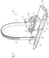
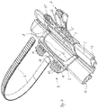
- Fig. 1a
- zeigt in perspektivischer Darstellung einen Teilbereich einer Ausführungsform eines erfindungsgemäßen Trägerprofils mit einer Ausführungsform einer erfindungsgemäßen Radschale bei montiertem Rad eines Fahrrads,
- Fig. 1b
- in einer Frontansicht die Darstellung gemäß
Fig. 1a , - Fig. 2
- Trägerprofil und Radschale gemäß den
Fig. 1a und1b in perspektivischer Darstellung und in einer Arretierstellung eines Spannbands, - Fig. 3
- die Anordnung gemäß
Fig. 2 in anderer Perspektive und - Fig. 4
- die Anordnung gemäß den
Fig. 2 und3 bei geöffnetem Spannband. - Ein Zweiradträger in Form eines Fahrradträgers weist gemäß den
Fig. 1a bis 4 ein Trägerprofil 2 auf, das aus Metall, vorliegend aus einer Leichtmetalllegierung, hergestellt ist. Das Trägerprofil 2 ist in montiertem Zustand auf einer Tragstruktur des Fahrradträgers befestigt. Der Fahrradträger selbst ist in fertig montiertem Zustand entweder als Heckträger oder als Dachträger ausgeführt und in einem Dachbereich oder einem Heckbereich eines Kraftfahrzeugs montierbar. - Das Trägerprofil 2 ist als Hohlprofil gestaltet, das im Bereich seiner Oberseite mit einer Rinnen- oder Keilform versehen ist, wie den
Fig. 1a und1b gut zu entnehmen ist. Im Bereich einer Unterseite sind Haltenuten vorgesehen, mittels der das Trägerprofil 2 auf der Tragstruktur des Fahrradträgers fixierbar ist. Das Trägerprofil 2 und die Radschale 3 bilden eine Trägerprofilanordnung im Sinne der Erfindung. - Auf dem Trägerprofil 2 angeordnet ist eine Radschale 3, die zur Fixierung eines Rads 1 eines Fahrrads dient. Das Rad 1 weist einen Reifen sowie eine Felge 4 auf, die mit Drahtspeichen 5 versehen ist.
- Die Radschale 3 weist einen Radschalenkörper 8 auf, der als Kunststoffbauteil gestaltet ist. Der Radschalenkörper 8 weist im Bereich seiner Oberseite einen keilartigen Aufnahmebereich A auf, der als Rahmenform mit einem innenliegenden, umlaufenden Rand 18 gestaltet ist, wie
Fig. 4 zu entnehmen ist. Innerhalb der Rahmenform ist der Aufnahmebereich A zu der Oberseite des Trägerprofils 2 hin offen. Die Rahmenform ist auf die Keil- oder Wannenform der Oberseite des Trägerprofils 2 abgestimmt, so dass die Rahmenform des Aufnahmebereichs A des Radschalen-körpers 8 mit ihrer Unterseite weitgehend flächig auf einer Oberfläche der Oberseite des Trägerprofils 2 aufliegt. Die Keil- oder Wannenform des Aufnahmebereichs A des Radschalenkörpers 8 bildet im Bereich einer Mitte der Oberseite des Trägerprofils 2 eine nicht näher bezeichnete Knickung oder Falzung, die formstabil ausgeführt und nach unten gerichtet ist und in eine Mittelrinne der Oberseite des Trägerprofils 2 eintaucht. Der Radschalenkörper 8 weist zudem an seinen gegenüberliegenden Seitenbereichen nach unten ragende Seitenschenkel auf, die in als Führungsprofilierungen dienenden Führungsstegen 14 enden. Die Führungsstege 14 sind nach innen und nach oben gekrümmt, so dass die die freien Endbereiche der Seitenschenkel bildenden Führungsstege 14 parallel zueinander nach oben ragen. Die Führungsstege 14 tauchen in als komplementäre Führungsprofilierungen dienende Führungsnuten 13 des Trägerprofils 2 ein, die an unteren Seitenabschnitten des Trägerprofils 2 vorgesehen und nach unten offen sind. Die nach unten weisenden Führungsnuten 13 des Trägerprofils 2 weisen einen im Wesentlichen rechteckigen Querschnitt auf. Die nach oben in die Führungsnuten 13 eintauchenden Führungsstege 14 der Seitenbereiche des Radschalenkörpers 8 sind im Querschnitt komplementär rechteckig gestaltet, um in den Führungsnuten 13 in Längsrichtung des Trägerprofils 2 gleitbeweglich gelagert zu sein. - Wie anhand der
Fig. 1b erkennbar ist, befindet sich zwischen dem Radschalenkörper 8 und der Außenkontur des Trägerprofils 2 in Hochrichtung ein gewisses Spiel von einem oder wenigen Millimetern. Dieses Spiel ist für eine Gleitbeweglichkeit des Radschalenkörpers 8 in Längsrichtung verantwortlich. - Der Radschalenkörper 8 weist auf Höhe der gegenüberliegenden Außenkanten des Trägerprofils 2 und damit im Bereich einer Oberseite des jeweiligen Seitenbereichs des Radschalenkörpers 8 jeweils einen Sicherungsschenkel 9, 11 auf, der mittels einer Schwenklagerung um eine Schwenkachse 10, 12 schwenkbeweglich an dem Radschalenkörper 8 gelagert ist. Die beiden Schwenkachsen 12 erstrecken sich parallel zueinander und parallel zu einer Mittellängsachse des Trägerprofils 2 und damit auch in Längsrichtung des Radschalenkörpers 8. Die jeweilige Scharnieranordnung für den jeweiligen Sicherungsschenkel 9 wird durch am Radschalenkörper 8 einerseits und am jeweiligen Sicherungsschenkel 9, 11 andererseits einstückig angeformte Scharnierhülsenabschnitte gebildet, durch die jeweils ein als Schwenkachse 10, 12 dienender Steckstift hindurchgesteckt ist. Die beiden Sicherungsschenkel 9, 11 auf gegenüberliegenden Seiten des Radschalenkörpers 8 sind identisch zueinander gestaltet. Beide Sicherungsschenkel 9, 11 weisen an ihrer Innenseite Stützprofilierungen 15 auf, die zumindest weitgehend quer zur Längserstreckung der jeweiligen Schwenkachse 10, 12 ausgerichtet sind und als von einer Oberfläche der Innenseite des jeweiligen Sicherungsschenkels 11 aus erhaben abragende und parallel zueinander ausgerichtete Stützstege gestaltet sind. Die Stützprofilierungen 15 sind einstückig am jeweiligen Sicherungsschenkel 9, 11 angeformt. Die Stützprofilierungen 15 dienen dazu, sich in fixiertem Zustand des Rads 1 gegen die Seitenflanken des Reifens des Rads 1 zu pressen und so die Rückhaltekraft für das Rad 1 zu erhöhen.
- In einer Freigabestellung sind die beiden Sicherungsschenkel 9, 11 so weit nach außen umgeklappt, dass sie nicht oder nahezu nicht über die Oberseiten der Seitenbereiche des Radschalenkörpers 8 nach oben abragen.
- An dem einen Sicherungsschenkel 11 ist ein flexibles Spannband 6 befestigt. An dem anderen Sicherungsschenkel 9, d.h. auf der gegenüberliegenden Seite des Radschalenkörpers 8, ist ein Spann- und Arretierschloss 7 befestigt. Das Spannband 6 ist als Rastband gestaltet und mit einem Endbereich an einer Außenseite des Sicherungsschenkels 11 positioniert und mittels eines Befestigungsniets 16, d.h. eines mechanischen Befestigungselements, an dem Sicherungsschenkel 11 gehalten. Der übrige Teil des Spannbands 6 ragt frei von dem Sicherungsschenkel 11 ab.
- Auch das Spann- und Arretierschloss 7 ist mittels eines Befestigungsniets 17 an einer Außenseite des Sicherungsschenkels 9 befestigt. Das Spann- und Arretierschloss 7 weist einen Spannhebel und eine Rastklinkenanordnung auf, wobei der Spannhebel manuell betätigbar ist.
- Um ein Rad 1 gemäß den
Fig. 1a und1b in der Radschale 3 und damit auf dem Trägerprofil 2 fixieren zu können, werden die beiden Sicherungsschenkel 9 und 11 nach außen in ihre Freigabestellung verschwenkt und das flexible Spannband 6 hängt frei von dem einen Sicherungsschenkel 11 ausgehend zur Seite oder nach unten. Nun wird das Rad 1 in den Aufnahmebereich A eingesetzt, wobei eine Lauffläche des Reifenmantels des Rads 1 direkt auf der Oberfläche des Trägerprofils 2 in dem von dem Randbereich 18 umgrenzten Abschnitt der Rahmenform des Radschalenkörpers 8 abgestützt ist. Anschließend werden die beiden Sicherungsschenkel 11 und 9 nach oben geschwenkt, bis die Stützprofilierungen 15 der beiden Sicherungsschenkel 9, 11 an gegenüberliegenden Seitenflanken des Reifenmantels des Rads 1 anliegen. Gleichzeitig oder anschließend wird das Spannband 6 durch die Radspeichen 5 des Rads 1 hindurchgeführt und übergreift die Felge 4. Das Spannband 6 wird in das Spann- und Arretierschloss 7 hineingeschoben und anschließend durch den Spannhebel gespannt, bis das Spannband 6 fest gegen die Felge 4 gezogen ist. Dadurch pressen sich zum einen zwangsläufig die Stützprofilierungen 15 der Sicherungsschenkel 11 und 9 gegen die Seitenflanken des Reifenmantels. Zum anderen werden die Sicherungsschenkel 9 und 11 aufgrund der durch die Spannung des Spannbands 6 bewirkten Zugkraft zwangsläufig nach oben gezogen. Da die Sicherungsschenkel 9 und 11 über die Scharnieranordnungen und die Schwenkachsen 10, 12 mit den Seitenbereichen des Radschalenkörpers 8 verbunden sind, werden hierdurch auch zwangsläufig die Seitenbereiche des Radschalenkörpers 8 nach oben gezogen. Dies führt dazu, dass die Führungsstege 14 ebenfalls nach oben gezogen werden und sich so gegen den jeweiligen Grund der jeweiligen Führungsnut 13 des Trägerprofils 2 pressen. Dadurch wird neben der Fixierung des Rads 1 in der Radschale 3 auch eine kraftschlüssige Fixierung des Radschalenkörpers 8 an dem Trägerprofil 2 erzielt, ohne dass zur Fixierung des Radschalenkörpers 8 an dem Trägerprofil 2 weitere Befestigungselemente notwendig sind. - Zum Öffnen des Spannbands 6 und zum Freigeben des Rads 1 wird in einfacher Weise nach dem Lösen des Spann- und Arretierschlosses 7 das Spannband 6 aus dem Spann- und Arretierschloss 7 nach oben herausgezogen, die beiden Sicherungsschenkel 9 und 11 werden aufgeklappt, wenn sie nicht ohnehin bereits durch ihr Eigengewicht nach außen und nach unten schwenken, und das Rad 1 kann entnommen werden.
Claims (9)
- Radschale (3) zur Aufnahme eines Rads (1) eines Zweirads, insbesondere eines Fahrrads, mit einem Radschalenkörper (8), der in montiertem Zustand auf einem Trägerprofil (2) einer Zweiradträgereinheit gehalten ist, wobei dem Radschalenkörper (8) ein flexibles Spannband (6) sowie ein Spann- und Arretierschloss (7) für das Spannband (6) zugeordnet sind, dadurch gekennzeichnet, dass das Spannband (6) einends an einem Sicherungsschenkel (11) gehalten ist, der relativ zu dem Radschalenkörper (8) seitlich neben einem Aufnahmebereich (A) für das Rad (1) um eine Schwenkachse (12) schwenkbeweglich gelagert ist, die derart in Längsrichtung des Radschalenkörpers (8) erstreckt ist, dass der Sicherungsschenkel (11) zwischen einer von dem Aufnahmebereich (A) weg ragenden Freigabestellung und einer zu dem Aufnahmebereich (A) hin ragenden Sicherungsstellung verschwenkbar ist.
- Radschale nach Anspruch 1, dadurch gekennzeichnet, dass das Spann- und Arretierschloss (7) an einem Seitenbereich des Radschalenkörpers (8) angeordnet ist, der gegenüberliegend zu dem Sicherungsschenkel (11) vorgesehen ist, an dem das Spannband (6) endseitig gehalten ist.
- Radschale nach Anspruch 2, dadurch gekennzeichnet, dass das Spann- und Arretierschloss (7) an einem weiteren Sicherungsschenkel (9) gehalten ist, der an dem Seitenbereich des Radschalenkörpers (8) um eine Schwenkachse (10) schwenkbeweglich gelagert ist, die derart in Längsrichtung des Radschalenkörpers (8) erstreckt ist, dass der Sicherungsschenkel (9) zwischen einer von dem Aufnahmebereich (A) weg ragenden Freigabestellung und einer zu dem Aufnahmebereich (A) hin ragenden Sicherungsstellung verschwenkbar ist.
- Radschale nach einem der vorhergehenden Ansprüche, dadurch gekennzeichnet, dass der Sicherungsschenkel (9, 11) an einer dem Aufnahmebereich (A) zugewandten Innenseite mit Stützprofilierungen (15) versehen ist, die sich bei aufgenommenem Rad (1) an dem Rad (1) abstützen.
- Radschale nach Anspruch 4, dadurch gekennzeichnet, dass die Stützprofilierungen (15) quer zur Schwenkachse (10, 12) des Sicherungsschenkels (9, 11) erstreckt sind.
- Radschale nach einem der vorhergehenden Ansprüche, dadurch gekennzeichnet, dass das Spannband (6) mit einem Stirnende mittels wenigstens eines mechanischen Befestigungselements (16) an dem Sicherungsschenkel (11) befestigt ist.
- Radschale nach einem der vorhergehenden Ansprüche, dadurch gekennzeichnet, dass das Spann- und Arretierschloss (7) mittels wenigstens eines mechanischen Befestigungselements (17) an dem Sicherungsschenkel (9) befestigt ist.
- Radschale nach einem der vorhergehenden Ansprüche, dadurch gekennzeichnet, dass das Spannband (6) und/oder das Spann- und Arretierschloss (7) jeweils außenseitig an dem jeweiligen Sicherungsschenkel (9, 11) angeordnet sind.
- Trägerprofilanordnung einer Zweiradträgereinheit mit einem Trägerprofil (2) sowie mit einer Radschale (3) nach dem Oberbegriff des Anspruchs 1 oder nach einem der vorhergehenden Ansprüche, dadurch gekennzeichnet, dass der Radschalenkörper (8) gleitbeweglich auf dem Trägerprofil (2) angeordnet ist, und dass das Trägerprofil (2) an gegenüberliegenden Seiten mit Führungsprofilierungen (13) versehen ist, in die komplementäre Führungsprofilierungen (14) des Radschalenkörpers (8) derart eingreifen, dass die zueinander komplementären Führungsprofilierungen (13, 14) bei einer Fixierung des Spannbands (6) an einem Radquerschnitt eines aufgenommenen Rads (1) kraftschlüssig gegeneinander verklemmt werden.
Applications Claiming Priority (1)
| Application Number | Priority Date | Filing Date | Title |
|---|---|---|---|
| DE102017215959.6A DE102017215959A1 (de) | 2017-09-11 | 2017-09-11 | Radschale zur Aufnahme eines Rads eines Zweirads sowie Trägerprofilanordnung einer Zweiradträgereinheit mit einem Trägerprofil und mit einer derartigen Radschale |
Publications (2)
| Publication Number | Publication Date |
|---|---|
| EP3453540A1 true EP3453540A1 (de) | 2019-03-13 |
| EP3453540B1 EP3453540B1 (de) | 2022-07-20 |
Family
ID=63077721
Family Applications (1)
| Application Number | Title | Priority Date | Filing Date |
|---|---|---|---|
| EP18185674.1A Active EP3453540B1 (de) | 2017-09-11 | 2018-07-26 | Radschale zur aufnahme eines rads eines zweirädrigen fahrzeugs |
Country Status (4)
| Country | Link |
|---|---|
| EP (1) | EP3453540B1 (de) |
| DE (1) | DE102017215959A1 (de) |
| DK (1) | DK3453540T3 (de) |
| PL (1) | PL3453540T3 (de) |
Cited By (2)
| Publication number | Priority date | Publication date | Assignee | Title |
|---|---|---|---|---|
| DE102021207883B3 (de) | 2021-07-22 | 2022-11-10 | Atera Gmbh | Trägersystem für ein Zweirad |
| AU2023316923B1 (en) * | 2022-10-27 | 2024-05-02 | Rhino Rack Australia Pty Limited | An item carrying device for a vehicle |
Citations (6)
| Publication number | Priority date | Publication date | Assignee | Title |
|---|---|---|---|---|
| DE8890092U1 (de) * | 1987-09-02 | 1990-08-23 | JS Products AB, Dalsjöfors | Befestigungsanordnung für ein Fahrrad |
| US20030189072A1 (en) * | 2002-04-09 | 2003-10-09 | Thule Sweden Ab | Rotatable strap assembly for a load carrier |
| US20070164065A1 (en) * | 2005-08-09 | 2007-07-19 | Davis Brian F | Adjustable bicycle wheel retainer |
| EP2562048B1 (de) * | 2011-08-25 | 2014-02-19 | Thule Sweden AB | Radhalter für einen Fahrradträger und Fahrradträger mit dem Radhalter |
| EP2952387A1 (de) * | 2014-06-05 | 2015-12-09 | Thule Sweden AB | Radhalter für einen Fahrradträger |
| US20160039354A1 (en) * | 2014-08-05 | 2016-02-11 | Thule Sweden Ab | Deployable Interference Mechanism For Variably Positionable Bicycle Wheel Anchor |
Family Cites Families (3)
| Publication number | Priority date | Publication date | Assignee | Title |
|---|---|---|---|---|
| WO1997008017A1 (de) * | 1995-08-25 | 1997-03-06 | Milz Produkte Ag | Dachträger zur befestigung eines fahrrads |
| US6431423B1 (en) * | 1999-11-23 | 2002-08-13 | Yakima Products, Inc. | Assembly for carrying a bicycle on a vehicle |
| DE102010015652B4 (de) | 2010-04-15 | 2017-05-18 | Atera Gmbh | Aufnahmevorrichtung für ein Rad eines Fahrrades |
-
2017
- 2017-09-11 DE DE102017215959.6A patent/DE102017215959A1/de not_active Ceased
-
2018
- 2018-07-26 PL PL18185674.1T patent/PL3453540T3/pl unknown
- 2018-07-26 EP EP18185674.1A patent/EP3453540B1/de active Active
- 2018-07-26 DK DK18185674.1T patent/DK3453540T3/da active
Patent Citations (6)
| Publication number | Priority date | Publication date | Assignee | Title |
|---|---|---|---|---|
| DE8890092U1 (de) * | 1987-09-02 | 1990-08-23 | JS Products AB, Dalsjöfors | Befestigungsanordnung für ein Fahrrad |
| US20030189072A1 (en) * | 2002-04-09 | 2003-10-09 | Thule Sweden Ab | Rotatable strap assembly for a load carrier |
| US20070164065A1 (en) * | 2005-08-09 | 2007-07-19 | Davis Brian F | Adjustable bicycle wheel retainer |
| EP2562048B1 (de) * | 2011-08-25 | 2014-02-19 | Thule Sweden AB | Radhalter für einen Fahrradträger und Fahrradträger mit dem Radhalter |
| EP2952387A1 (de) * | 2014-06-05 | 2015-12-09 | Thule Sweden AB | Radhalter für einen Fahrradträger |
| US20160039354A1 (en) * | 2014-08-05 | 2016-02-11 | Thule Sweden Ab | Deployable Interference Mechanism For Variably Positionable Bicycle Wheel Anchor |
Cited By (4)
| Publication number | Priority date | Publication date | Assignee | Title |
|---|---|---|---|---|
| DE102021207883B3 (de) | 2021-07-22 | 2022-11-10 | Atera Gmbh | Trägersystem für ein Zweirad |
| EP4122771A1 (de) * | 2021-07-22 | 2023-01-25 | ATERA GmbH | Trägersystem für ein zweirad |
| AU2023316923B1 (en) * | 2022-10-27 | 2024-05-02 | Rhino Rack Australia Pty Limited | An item carrying device for a vehicle |
| WO2024086868A1 (en) * | 2022-10-27 | 2024-05-02 | Rhino Rack Australia Pty Limited | An item carrying device for a vehicle |
Also Published As
| Publication number | Publication date |
|---|---|
| PL3453540T3 (pl) | 2023-02-20 |
| DE102017215959A1 (de) | 2019-03-14 |
| DK3453540T3 (da) | 2022-10-24 |
| EP3453540B1 (de) | 2022-07-20 |
Similar Documents
| Publication | Publication Date | Title |
|---|---|---|
| DE602004010644T2 (de) | Scheibenwischervorrichtung | |
| DE202011001237U1 (de) | Verzurröse | |
| DE2551646A1 (de) | Buegelfoermiger lasttraeger zur befestigung an einem fahrzeugdach | |
| DE4427445C1 (de) | Lagervorrichtung, insbesondere für schwenkbar gelagerte Sonnenblenden von Fahrzeugen | |
| EP3453540A1 (de) | Radschale zur aufnahme eines rads eines zweirads sowie trägerprofilanordnung einer zweiradträgereinheit mit einem trägerprofil und mit einer derartigen radschale | |
| DE4108656C1 (de) | ||
| DE60103850T2 (de) | Einstückig angeformte dachträger | |
| DE2757662C3 (de) | Ladefläche oder Brücke für Transportmittel | |
| DE3405357A1 (de) | Dachlasttraeger fuer regenrinnenlose kraftwagen (d1/84) | |
| DE2221344A1 (de) | Sitzelement | |
| EP0065218A1 (de) | Trägeranordnung | |
| DE4106493C1 (en) | Folding roof on vehicle - uses leading and rear transverse slides releasably connectable to roof | |
| DE602005004372T2 (de) | Kraftfahrzeug mit mindestens zwei Scheibenwischvorrichtungen | |
| EP1897725B1 (de) | Abspannanordnung für einen heckseitigen Abschnitt eines Verdeckbezugs und Cabriolet | |
| DE102008045144A1 (de) | Transportwagen | |
| EP1103399B1 (de) | Klappverdeck für Cabriolets mit einem äusseren Verdeckbezug mit integrierter Scheibe und mit einem inneren Verdeckbezug | |
| DE10356382B4 (de) | Kraftfahrzeug mit einem Dachkanal | |
| AT500944B1 (de) | Vorrichtung zum spannen von seitenplanen eines fahrzeugaufbaus | |
| DE1951844U (de) | Dachverdeck-befestigungsvorrichtung fuer kabriolet-fahrzeuge. | |
| DE102008007952B4 (de) | Abspannanordnung für einen heckseitigen Endabschnitt eines Verdeckbezugs | |
| DE10321343B4 (de) | Fahrzeug mit einer Abdeckplatte für einen Stauraum, insbesondere für eine Reserveradmulde | |
| DE19648558A1 (de) | Kraftfahrzeugtür | |
| DE20303264U1 (de) | Koffer mit Verschlussvorrichtung | |
| DE19803404B4 (de) | Faltschiebedach für ein Fahrzeug | |
| EP2332814A2 (de) | Zusammenlegbares bzw. zusammenklappbares Fahrrad |
Legal Events
| Date | Code | Title | Description |
|---|---|---|---|
| PUAI | Public reference made under article 153(3) epc to a published international application that has entered the european phase |
Free format text: ORIGINAL CODE: 0009012 |
|
| STAA | Information on the status of an ep patent application or granted ep patent |
Free format text: STATUS: THE APPLICATION HAS BEEN PUBLISHED |
|
| AK | Designated contracting states |
Kind code of ref document: A1 Designated state(s): AL AT BE BG CH CY CZ DE DK EE ES FI FR GB GR HR HU IE IS IT LI LT LU LV MC MK MT NL NO PL PT RO RS SE SI SK SM TR |
|
| AX | Request for extension of the european patent |
Extension state: BA ME |
|
| STAA | Information on the status of an ep patent application or granted ep patent |
Free format text: STATUS: REQUEST FOR EXAMINATION WAS MADE |
|
| 17P | Request for examination filed |
Effective date: 20190820 |
|
| RBV | Designated contracting states (corrected) |
Designated state(s): AL AT BE BG CH CY CZ DE DK EE ES FI FR GB GR HR HU IE IS IT LI LT LU LV MC MK MT NL NO PL PT RO RS SE SI SK SM TR |
|
| STAA | Information on the status of an ep patent application or granted ep patent |
Free format text: STATUS: EXAMINATION IS IN PROGRESS |
|
| 17Q | First examination report despatched |
Effective date: 20210624 |
|
| RIC1 | Information provided on ipc code assigned before grant |
Ipc: B60B 1/00 20060101ALN20211213BHEP Ipc: B60R 9/10 20060101ALI20211213BHEP Ipc: B60B 30/06 20060101AFI20211213BHEP |
|
| RIC1 | Information provided on ipc code assigned before grant |
Ipc: B60B 1/00 20060101ALN20211220BHEP Ipc: B60R 9/10 20060101ALI20211220BHEP Ipc: B60B 30/06 20060101AFI20211220BHEP |
|
| GRAP | Despatch of communication of intention to grant a patent |
Free format text: ORIGINAL CODE: EPIDOSNIGR1 |
|
| STAA | Information on the status of an ep patent application or granted ep patent |
Free format text: STATUS: GRANT OF PATENT IS INTENDED |
|
| RIC1 | Information provided on ipc code assigned before grant |
Ipc: B60B 1/00 20060101ALN20220114BHEP Ipc: B60R 9/10 20060101ALI20220114BHEP Ipc: B60B 30/06 20060101AFI20220114BHEP |
|
| INTG | Intention to grant announced |
Effective date: 20220211 |
|
| GRAS | Grant fee paid |
Free format text: ORIGINAL CODE: EPIDOSNIGR3 |
|
| GRAA | (expected) grant |
Free format text: ORIGINAL CODE: 0009210 |
|
| STAA | Information on the status of an ep patent application or granted ep patent |
Free format text: STATUS: THE PATENT HAS BEEN GRANTED |
|
| AK | Designated contracting states |
Kind code of ref document: B1 Designated state(s): AL AT BE BG CH CY CZ DE DK EE ES FI FR GB GR HR HU IE IS IT LI LT LU LV MC MK MT NL NO PL PT RO RS SE SI SK SM TR |
|
| REG | Reference to a national code |
Ref country code: CH Ref legal event code: EP |
|
| REG | Reference to a national code |
Ref country code: DE Ref legal event code: R096 Ref document number: 502018010175 Country of ref document: DE |
|
| REG | Reference to a national code |
Ref country code: AT Ref legal event code: REF Ref document number: 1505297 Country of ref document: AT Kind code of ref document: T Effective date: 20220815 |
|
| REG | Reference to a national code |
Ref country code: IE Ref legal event code: FG4D Free format text: LANGUAGE OF EP DOCUMENT: GERMAN |
|
| REG | Reference to a national code |
Ref country code: FI Ref legal event code: FGE |
|
| REG | Reference to a national code |
Ref country code: DK Ref legal event code: T3 Effective date: 20221020 |
|
| REG | Reference to a national code |
Ref country code: SE Ref legal event code: TRGR |
|
| REG | Reference to a national code |
Ref country code: NL Ref legal event code: FP |
|
| REG | Reference to a national code |
Ref country code: LT Ref legal event code: MG9D |
|
| PG25 | Lapsed in a contracting state [announced via postgrant information from national office to epo] |
Ref country code: RS Free format text: LAPSE BECAUSE OF FAILURE TO SUBMIT A TRANSLATION OF THE DESCRIPTION OR TO PAY THE FEE WITHIN THE PRESCRIBED TIME-LIMIT Effective date: 20220720 Ref country code: PT Free format text: LAPSE BECAUSE OF FAILURE TO SUBMIT A TRANSLATION OF THE DESCRIPTION OR TO PAY THE FEE WITHIN THE PRESCRIBED TIME-LIMIT Effective date: 20221121 Ref country code: NO Free format text: LAPSE BECAUSE OF FAILURE TO SUBMIT A TRANSLATION OF THE DESCRIPTION OR TO PAY THE FEE WITHIN THE PRESCRIBED TIME-LIMIT Effective date: 20221020 Ref country code: LV Free format text: LAPSE BECAUSE OF FAILURE TO SUBMIT A TRANSLATION OF THE DESCRIPTION OR TO PAY THE FEE WITHIN THE PRESCRIBED TIME-LIMIT Effective date: 20220720 Ref country code: LT Free format text: LAPSE BECAUSE OF FAILURE TO SUBMIT A TRANSLATION OF THE DESCRIPTION OR TO PAY THE FEE WITHIN THE PRESCRIBED TIME-LIMIT Effective date: 20220720 Ref country code: ES Free format text: LAPSE BECAUSE OF FAILURE TO SUBMIT A TRANSLATION OF THE DESCRIPTION OR TO PAY THE FEE WITHIN THE PRESCRIBED TIME-LIMIT Effective date: 20220720 |
|
| PG25 | Lapsed in a contracting state [announced via postgrant information from national office to epo] |
Ref country code: IS Free format text: LAPSE BECAUSE OF FAILURE TO SUBMIT A TRANSLATION OF THE DESCRIPTION OR TO PAY THE FEE WITHIN THE PRESCRIBED TIME-LIMIT Effective date: 20221120 Ref country code: HR Free format text: LAPSE BECAUSE OF FAILURE TO SUBMIT A TRANSLATION OF THE DESCRIPTION OR TO PAY THE FEE WITHIN THE PRESCRIBED TIME-LIMIT Effective date: 20220720 Ref country code: GR Free format text: LAPSE BECAUSE OF FAILURE TO SUBMIT A TRANSLATION OF THE DESCRIPTION OR TO PAY THE FEE WITHIN THE PRESCRIBED TIME-LIMIT Effective date: 20221021 |
|
| REG | Reference to a national code |
Ref country code: CH Ref legal event code: PL |
|
| REG | Reference to a national code |
Ref country code: BE Ref legal event code: MM Effective date: 20220731 |
|
| REG | Reference to a national code |
Ref country code: DE Ref legal event code: R097 Ref document number: 502018010175 Country of ref document: DE |
|
| PG25 | Lapsed in a contracting state [announced via postgrant information from national office to epo] |
Ref country code: SM Free format text: LAPSE BECAUSE OF FAILURE TO SUBMIT A TRANSLATION OF THE DESCRIPTION OR TO PAY THE FEE WITHIN THE PRESCRIBED TIME-LIMIT Effective date: 20220720 Ref country code: RO Free format text: LAPSE BECAUSE OF FAILURE TO SUBMIT A TRANSLATION OF THE DESCRIPTION OR TO PAY THE FEE WITHIN THE PRESCRIBED TIME-LIMIT Effective date: 20220720 Ref country code: MC Free format text: LAPSE BECAUSE OF FAILURE TO SUBMIT A TRANSLATION OF THE DESCRIPTION OR TO PAY THE FEE WITHIN THE PRESCRIBED TIME-LIMIT Effective date: 20220720 Ref country code: LU Free format text: LAPSE BECAUSE OF NON-PAYMENT OF DUE FEES Effective date: 20220726 Ref country code: LI Free format text: LAPSE BECAUSE OF NON-PAYMENT OF DUE FEES Effective date: 20220731 Ref country code: CZ Free format text: LAPSE BECAUSE OF FAILURE TO SUBMIT A TRANSLATION OF THE DESCRIPTION OR TO PAY THE FEE WITHIN THE PRESCRIBED TIME-LIMIT Effective date: 20220720 Ref country code: CH Free format text: LAPSE BECAUSE OF NON-PAYMENT OF DUE FEES Effective date: 20220731 |
|
| PLBE | No opposition filed within time limit |
Free format text: ORIGINAL CODE: 0009261 |
|
| STAA | Information on the status of an ep patent application or granted ep patent |
Free format text: STATUS: NO OPPOSITION FILED WITHIN TIME LIMIT |
|
| PG25 | Lapsed in a contracting state [announced via postgrant information from national office to epo] |
Ref country code: SK Free format text: LAPSE BECAUSE OF FAILURE TO SUBMIT A TRANSLATION OF THE DESCRIPTION OR TO PAY THE FEE WITHIN THE PRESCRIBED TIME-LIMIT Effective date: 20220720 Ref country code: EE Free format text: LAPSE BECAUSE OF FAILURE TO SUBMIT A TRANSLATION OF THE DESCRIPTION OR TO PAY THE FEE WITHIN THE PRESCRIBED TIME-LIMIT Effective date: 20220720 Ref country code: BE Free format text: LAPSE BECAUSE OF NON-PAYMENT OF DUE FEES Effective date: 20220731 |
|
| 26N | No opposition filed |
Effective date: 20230421 |
|
| P01 | Opt-out of the competence of the unified patent court (upc) registered |
Effective date: 20230519 |
|
| PG25 | Lapsed in a contracting state [announced via postgrant information from national office to epo] |
Ref country code: AL Free format text: LAPSE BECAUSE OF FAILURE TO SUBMIT A TRANSLATION OF THE DESCRIPTION OR TO PAY THE FEE WITHIN THE PRESCRIBED TIME-LIMIT Effective date: 20220720 |
|
| PG25 | Lapsed in a contracting state [announced via postgrant information from national office to epo] |
Ref country code: IE Free format text: LAPSE BECAUSE OF NON-PAYMENT OF DUE FEES Effective date: 20220726 |
|
| PG25 | Lapsed in a contracting state [announced via postgrant information from national office to epo] |
Ref country code: SI Free format text: LAPSE BECAUSE OF FAILURE TO SUBMIT A TRANSLATION OF THE DESCRIPTION OR TO PAY THE FEE WITHIN THE PRESCRIBED TIME-LIMIT Effective date: 20220720 |
|
| PG25 | Lapsed in a contracting state [announced via postgrant information from national office to epo] |
Ref country code: HU Free format text: LAPSE BECAUSE OF FAILURE TO SUBMIT A TRANSLATION OF THE DESCRIPTION OR TO PAY THE FEE WITHIN THE PRESCRIBED TIME-LIMIT; INVALID AB INITIO Effective date: 20180726 |
|
| PG25 | Lapsed in a contracting state [announced via postgrant information from national office to epo] |
Ref country code: MK Free format text: LAPSE BECAUSE OF FAILURE TO SUBMIT A TRANSLATION OF THE DESCRIPTION OR TO PAY THE FEE WITHIN THE PRESCRIBED TIME-LIMIT Effective date: 20220720 Ref country code: CY Free format text: LAPSE BECAUSE OF FAILURE TO SUBMIT A TRANSLATION OF THE DESCRIPTION OR TO PAY THE FEE WITHIN THE PRESCRIBED TIME-LIMIT Effective date: 20220720 |
|
| PG25 | Lapsed in a contracting state [announced via postgrant information from national office to epo] |
Ref country code: IT Free format text: LAPSE BECAUSE OF FAILURE TO SUBMIT A TRANSLATION OF THE DESCRIPTION OR TO PAY THE FEE WITHIN THE PRESCRIBED TIME-LIMIT Effective date: 20220720 |
|
| PG25 | Lapsed in a contracting state [announced via postgrant information from national office to epo] |
Ref country code: TR Free format text: LAPSE BECAUSE OF FAILURE TO SUBMIT A TRANSLATION OF THE DESCRIPTION OR TO PAY THE FEE WITHIN THE PRESCRIBED TIME-LIMIT Effective date: 20220720 |
|
| PG25 | Lapsed in a contracting state [announced via postgrant information from national office to epo] |
Ref country code: BG Free format text: LAPSE BECAUSE OF FAILURE TO SUBMIT A TRANSLATION OF THE DESCRIPTION OR TO PAY THE FEE WITHIN THE PRESCRIBED TIME-LIMIT Effective date: 20220720 |
|
| PGFP | Annual fee paid to national office [announced via postgrant information from national office to epo] |
Ref country code: NL Payment date: 20240722 Year of fee payment: 7 |
|
| REG | Reference to a national code |
Ref country code: AT Ref legal event code: MM01 Ref document number: 1505297 Country of ref document: AT Kind code of ref document: T Effective date: 20230726 |
|
| PG25 | Lapsed in a contracting state [announced via postgrant information from national office to epo] |
Ref country code: MT Free format text: LAPSE BECAUSE OF FAILURE TO SUBMIT A TRANSLATION OF THE DESCRIPTION OR TO PAY THE FEE WITHIN THE PRESCRIBED TIME-LIMIT Effective date: 20220720 |
|
| PGFP | Annual fee paid to national office [announced via postgrant information from national office to epo] |
Ref country code: FI Payment date: 20240719 Year of fee payment: 7 Ref country code: DE Payment date: 20240723 Year of fee payment: 7 |
|
| PGFP | Annual fee paid to national office [announced via postgrant information from national office to epo] |
Ref country code: DK Payment date: 20240722 Year of fee payment: 7 |
|
| PGFP | Annual fee paid to national office [announced via postgrant information from national office to epo] |
Ref country code: GB Payment date: 20240723 Year of fee payment: 7 |
|
| PGFP | Annual fee paid to national office [announced via postgrant information from national office to epo] |
Ref country code: FR Payment date: 20240724 Year of fee payment: 7 |
|
| PG25 | Lapsed in a contracting state [announced via postgrant information from national office to epo] |
Ref country code: AT Free format text: LAPSE BECAUSE OF NON-PAYMENT OF DUE FEES Effective date: 20230726 |
|
| PGFP | Annual fee paid to national office [announced via postgrant information from national office to epo] |
Ref country code: PL Payment date: 20240701 Year of fee payment: 7 |
|
| PG25 | Lapsed in a contracting state [announced via postgrant information from national office to epo] |
Ref country code: AT Free format text: LAPSE BECAUSE OF NON-PAYMENT OF DUE FEES Effective date: 20230726 |
|
| PGFP | Annual fee paid to national office [announced via postgrant information from national office to epo] |
Ref country code: SE Payment date: 20240722 Year of fee payment: 7 |
|
| REG | Reference to a national code |
Ref country code: DE Ref legal event code: R119 Ref document number: 502018010175 Country of ref document: DE |
|
| REG | Reference to a national code |
Ref country code: DK Ref legal event code: EBP Effective date: 20250731 |
|
| REG | Reference to a national code |
Ref country code: NL Ref legal event code: MM Effective date: 20250801 |
|
| GBPC | Gb: european patent ceased through non-payment of renewal fee |
Effective date: 20250726 |
|
| PG25 | Lapsed in a contracting state [announced via postgrant information from national office to epo] |
Ref country code: GB Free format text: LAPSE BECAUSE OF NON-PAYMENT OF DUE FEES Effective date: 20250726 |
|
| PG25 | Lapsed in a contracting state [announced via postgrant information from national office to epo] |
Ref country code: DE Free format text: LAPSE BECAUSE OF NON-PAYMENT OF DUE FEES Effective date: 20260203 |
|
| PG25 | Lapsed in a contracting state [announced via postgrant information from national office to epo] |
Ref country code: FI Free format text: LAPSE BECAUSE OF NON-PAYMENT OF DUE FEES Effective date: 20250726 |
|
| PGFP | Annual fee paid to national office [announced via postgrant information from national office to epo] |
Ref country code: AT Payment date: 20260410 Year of fee payment: 5 |
|
| PG25 | Lapsed in a contracting state [announced via postgrant information from national office to epo] |
Ref country code: NL Free format text: LAPSE BECAUSE OF NON-PAYMENT OF DUE FEES Effective date: 20250801 |
|
| PG25 | Lapsed in a contracting state [announced via postgrant information from national office to epo] |
Ref country code: FR Free format text: LAPSE BECAUSE OF NON-PAYMENT OF DUE FEES Effective date: 20250731 |