EP3447457B1 - Boîtier pour un dispositif de pesage - Google Patents
Boîtier pour un dispositif de pesage Download PDFInfo
- Publication number
- EP3447457B1 EP3447457B1 EP18199829.5A EP18199829A EP3447457B1 EP 3447457 B1 EP3447457 B1 EP 3447457B1 EP 18199829 A EP18199829 A EP 18199829A EP 3447457 B1 EP3447457 B1 EP 3447457B1
- Authority
- EP
- European Patent Office
- Prior art keywords
- housing
- frame
- base plate
- weighing device
- upper portion
- Prior art date
- Legal status (The legal status is an assumption and is not a legal conclusion. Google has not performed a legal analysis and makes no representation as to the accuracy of the status listed.)
- Active
Links
- 238000005303 weighing Methods 0.000 title claims description 37
- 238000000034 method Methods 0.000 claims description 4
- 230000000295 complement effect Effects 0.000 claims description 3
- 238000007789 sealing Methods 0.000 description 43
- 230000007613 environmental effect Effects 0.000 description 5
- 239000000463 material Substances 0.000 description 5
- 239000000428 dust Substances 0.000 description 3
- 230000000694 effects Effects 0.000 description 3
- 230000002093 peripheral effect Effects 0.000 description 3
- 230000005540 biological transmission Effects 0.000 description 2
- 230000001419 dependent effect Effects 0.000 description 2
- 238000005259 measurement Methods 0.000 description 2
- 229920001296 polysiloxane Polymers 0.000 description 2
- 238000005352 clarification Methods 0.000 description 1
- 230000006835 compression Effects 0.000 description 1
- 238000007906 compression Methods 0.000 description 1
- 239000004020 conductor Substances 0.000 description 1
- 238000005553 drilling Methods 0.000 description 1
- 239000013013 elastic material Substances 0.000 description 1
- 230000007774 longterm Effects 0.000 description 1
- 230000035515 penetration Effects 0.000 description 1
- 230000005855 radiation Effects 0.000 description 1
- 230000001105 regulatory effect Effects 0.000 description 1
- 239000003566 sealing material Substances 0.000 description 1
- 230000000087 stabilizing effect Effects 0.000 description 1
Images

Classifications
-
- G—PHYSICS
- G01—MEASURING; TESTING
- G01G—WEIGHING
- G01G21/00—Details of weighing apparatus
- G01G21/28—Frames, Housings
-
- G—PHYSICS
- G01—MEASURING; TESTING
- G01G—WEIGHING
- G01G21/00—Details of weighing apparatus
- G01G21/30—Means for preventing contamination by dust
-
- H—ELECTRICITY
- H05—ELECTRIC TECHNIQUES NOT OTHERWISE PROVIDED FOR
- H05K—PRINTED CIRCUITS; CASINGS OR CONSTRUCTIONAL DETAILS OF ELECTRIC APPARATUS; MANUFACTURE OF ASSEMBLAGES OF ELECTRICAL COMPONENTS
- H05K5/00—Casings, cabinets or drawers for electric apparatus
- H05K5/02—Details
Definitions
- the invention relates to a housing for a weighing device.
- Housings for weighing devices are known in many forms.
- Known housings for weighing devices often consist of a base plate on which the weighing device is arranged.
- the weighing device can, for example, comprise a sensor that works according to the principle of electromagnetic force compensation.
- Such force sensors typically include a Roberval link mechanism connected to one or more transmission levers as required.
- the load force to be detected acts on the moving part of the Roberval mechanism, which is connected to the first transmission lever.
- At the end of the last lever is a coil that is held at a constant height position in a magnetic field.
- the coil arranged on the last lever is supplied with a current which is regulated in such a way that the predetermined height position of the last lever is kept constant given the load force currently acting.
- the value of the current through the coil is thus a measure of the detected load force.
- All of the components that are required to record the load force ie the sensor, the control electronics and, if necessary, a device for processing the measured value or values recorded, can be arranged on the base plate of the housing.
- the housing is usually designed to be essentially tight by means of a housing upper part, which covers the upper side of the base plate, to protect against environmental influences, such as in particular dust and moisture.
- a load carrier arm and, on the other hand, the contacts for delivering the electrical or electronic measurement signals must be led out of the housing.
- the load carrier arm is usually led out through an opening on the top or cover side of the housing.
- the breakthrough is also sealed against environmental influences by means of a seal.
- labyrinth seals come into consideration as a seal, with a first sealing part being arranged in the opening of the housing or, surrounding the opening, on the upper side of the housing. This first sealing part is penetrated by the load carrier arm without contact as far as possible.
- the load carrier arm is in this case connected to a second sealing part which, together with the first sealing part, forms an annular space which is labyrinthine in a vertical section. This achieves a contact-free sealing of the opening in the housing for the passage of the load carrier arm, which therefore does not cause any force shunt.
- Cable bushings or plug contacts for transmitting the electrical measurement signals from the housing can be provided on the underside of the housing, ie on the underside of the base plate.
- Such units consisting of a housing and a weighing device arranged therein are referred to as load cells in the context of the present description.
- load cells are often installed in complex weighing devices, for example multi-track weighing devices.
- the load cells are usually mounted with their base plate on a machine frame of the complex weighing device.
- a scale is known in which a housing top part covering the weighing mechanism is attached indirectly to the base plate by guiding two frame elements arranged on the base plate down to the underside of the top side of the housing in order to fix the housing to the frame elements using suitable screw connections.
- the invention is based on the object of creating a housing for a weighing device in which the interior of the housing between a base plate and a housing upper part is sealed off from the environment in a simple manner and with long-term stability. At the same time, the housing should be connected to the base plate in a simple manner.
- the housing according to the invention for a weighing device which can be connected to a carrier element, has a base plate on which the weighing device can be mounted or which is integral with the weighing device or a component of the weighing device.
- a peripheral elastic sealing element is arranged on the underside of the housing.
- the sealing element is designed in such a way that a circumferential annular gap between the outer peripheral area of the underside of the base plate and the surface of the carrier element is sealed when the housing is mounted on the surface with a defined contact pressure acting on the underside of the base plate and the upper side of the carrier element. This protects cable bushings through the base plate into the machine frame or electrical contacts, which are provided on the underside of the base plate, against environmental influences when the housing and carrier element are in the assembled state.
- the sealing element is designed in such a way that during assembly it is elastically deformed by being subjected to the contact pressure between the underside of the base plate and the surface of the carrier element.
- the sealing element consists of an elastic material, for example an elastic plastic such as silicone.
- the elasticity of the material and the geometry of the sealing element can be matched to one another in such a way that an adequate sealing effect is ensured.
- the material of the sealing element can be adapted to the application. For example, in the case of applications in the food sector, a material can be used that has the appropriate suitability or approval from the responsible authorities.
- a magnetically and/or electrically conductive material can be used for the sealing element in order to make the seal additionally impervious to electromechanical radiation and to improve the electromagnetic compatibility of the weighing device provided in the housing or of the load cell consisting of the housing and the weighing device, at least in to ensure the assembled state of the housing and carrier element.
- a frame is connected to the base plate or formed in one piece with it for mounting the housing upper part.
- the upper part of the housing can be connected to the frame so that a contact pressure sufficient for the sealing effect can be generated for pressing the end face of the side wall of the upper part of the housing against the sealing element.
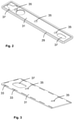
- the housing 1 shown in a sectional side view for a weighing device consists of a base plate 3 and a housing upper part 5 connected to the base plate 3, which has a cover wall 5a and a peripheral side wall 5b.
- the upper part of the housing thus has an essentially pot-shaped or trough-shaped form. It is of course not necessary for the housing 5 or the housing upper part 5 to have an essentially cuboid shape, as is shown in 1 is shown.
- the base plate also does not have to have an essentially planar structure, but can be adapted to the structure of a support element 7 on which the housing 1 is to be mounted.
- the carrier element 7 can, for example, be part of a machine frame of a complex device, such as a multi-track weighing device.
- Components of a weighing device can be arranged on the base plate 3, for example an electromechanical force sensor for detecting a load force and other mechanical or electrical or electronic components which are intended for example for converting the load force into an electrical signal.
- the electrical signal can be an analog signal or a signal that contains digital measured values.
- the base plate 3 can also be designed as an integral part of a component of the weighing device, in particular as part of the electromechanical force sensor, which can work, for example, according to the principle of electromagnetic force compensation.
- the purpose of the housing 1 is to protect the components of the weighing device located inside the housing against environmental influences, in particular dust, dirt and moisture.
- a load carrier arm, not shown in detail, of the weighing device or of the force sensor of the weighing device must of course be led out of the interior of the housing 1 . This is done via a breakthrough 9, which is at the in 1 illustrated embodiment of the housing 1 is formed in the cover wall 5a of the upper housing part 5.
- a first labyrinth sealing part 11 is inserted into the opening 9, the upper area of which interacts with the lower area of a second labyrinth sealing part 12, which can be fastened to the load arm of the force sensor, which is not shown in detail.
- the lower area of the second labyrinth sealing part surrounds the upper area of the first labyrinth sealing part 11 without contact in order to avoid a force shunt when the load force to be detected is introduced.
- annular space 13 with a labyrinthine cross section is created, which prevents or at least reduces the penetration of dust, dirt or excessive humidity in the form of droplets etc. into the interior of the housing.
- the load arm can also be brought out on the side wall of the upper part of the housing.
- a weighing device with a plurality of load arms can also be arranged in the housing, which can be guided to the outside via one or more openings in the housing.
- the one or more load arms can also be guided outwards via the base plate 3 .
- a frame 15 which can include a plurality of struts or ribs 17 , is arranged on the base plate 3 for fastening and stabilizing the housing upper part 5 .
- a strut 17 can be provided on each longitudinal side of the base plate 3 .
- one or more struts can of course also be provided between the two outer struts 17 .
- the longitudinal struts 17 can be connected by further transverse struts (not shown).
- the upper housing part 5 is placed on the frame 15, this overlapping.
- the upper part of the housing can be connected to the frame by a screw connection using one or more screws which pass through the upper part of the housing and engage in a respective strut 17 .
- the first labyrinth sealing part 11 can simultaneously serve as a mounting part for fixing the upper housing part 5 to the frame 15 .
- the lower area of the essentially cylindrical first labyrinth sealing part 11 has a thread which engages in a complementary thread in the frame or in the relevant strut 17 .
- the upper housing part 5 is pressed with its cover wall 5a against the upper side of the relevant strut. The housing upper part 5 is thus subjected to a vertically acting contact pressure.
- the frame 15 or the struts 17 can be connected to the base plate 3 by a screw connection.
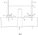
- a screw connection In 1 only a single screw connection is shown for clarification, with a screw 19 passing through the base plate 3 from below and engaging in a vertically extending part of an associated strut 17 which has a bore 21 with an internal thread for this purpose.
- a screw connection can also be provided for fastening the housing 1 to the carrier element 7 . From this one is in 1 also only a single screw 23 is shown schematically, which passes through the carrier element 7 from below and engages in a threaded hole in the underside of the base plate 3 .
- the plug-in connection 25 has contacts, not shown in detail, which can be contacted by means of a plug, which are accessible through a corresponding access opening 27 which is formed in the carrier element 7 .
- the contacting itself can of course be done by means of a plug or other suitable means.
- the base plate 3 can also have an opening through which corresponding electrical lines can be routed into the interior of the housing.
- a sealing element 29 is provided, which is arranged circumferentially on the lower outer edge of the base plate 3 .
- This ring-shaped sealing element 29 consists of a sufficiently flexible, elastic sealing material, for example a plastic such as silicone.
- the ring-shaped sealing element 29 is not arranged between the underside of the upper part of the housing and the upper side of the base plate, as in the case of previously customary housings for a weighing device, in order merely to produce a sealing effect between these two elements. Rather, the annular sealing element 29, as from 2 visible, which is an enlarged partial section along the plane AA in 1 represents, arranged below the outer edge area of the base plate 3 and also serves to seal a space within the annular sealing element 29 and below the underside of the base plate 3 against the surface of the carrier element 7. This is also the plug-in connection 25 or an opening for the passage sealed by electrical lines in the base plate 3 from the environment (above the support element 7). This of course also applies to all other components of the housing 1 or the weighing device accommodated therein which are to be protected against environmental influences and which are provided on the underside of the base plate 3 within the annular sealing element 29 or are accessible via this housing outer surface.
- the circumferential sealing element 29 is designed in such a way that its cross section protrudes beyond the outer circumference, i.e. the essentially vertically running outside of the base plate 3, so that the lower, circumferential end face 5c of the side wall 5b also acts on the upper side of the circumferential sealing element 29 when the housing is mounted on the carrier element 7 .
- the pressing force of the end face 5c of the side wall 5b is dependent, among other things, on the geometry and the material of the sealing element 29 and the geometry of the side wall 5b.
- a sealing element 29 used with a cross section whose top is substantially flat and horizontal, the Side wall 5b is preferably designed in such a way that the lower end face 5c projects beyond the underside 3a of the base plate 3 in the outer edge region of the base plate 3. In this way it can be ensured that in the area of the contact surface of the end face 5c of the sealing element 29, a contact pressure force is generated by the sealing element 29 which is sufficient to ensure the seal, even if the underside 3a of the base plate 3 covers the inner part of the horizontally running upper side of the annular Sealing element 29 is applied and as a result the sealing element 29 is already undergoing a partial deformation or compression in the area of the impact surface of the end face 5c.
Claims (10)
- Boîtier destiné à un dispositif de pesage et pouvant être relié à un élément porteur,(a) comportant une plaque de base (3) sur laquelle le dispositif de pesage peut être monté ou laquelle est formée d'un seul tenant avec le dispositif de pesage ou un composant du dispositif de pesage,(b) et comportant une partie supérieure de boîtier (5) qui peut être reliée à la plaque de base (3) et qui comporte une paroi de couvercle (5a) et une paroi latérale circonférentielle (5b),(c) et comportant un passage (9) étanchéifié par un joint (11, 12) dans la paroi (5a, 5b) de la partie supérieure de boîtier (5) pour le passage d'un bras porteur de charge,
caractérisé en ce(d) qu'en vue du montage de la partie supérieure de boîtier (5), un cadre (15) est relié à la plaque de base (3) ou est formé d'un seul tenant avec celle-ci, et(e) que la partie supérieure de boîtier (5) est fixée au cadre (15) au moyen d'une première partie de joint (11). - Boîtier selon la revendication 1, caractérisé en ce que le joint (11, 12) est un joint labyrinthe, la première partie de joint étant conçue comme une première partie de joint labyrinthe (11) et étant disposée dans le passage (9).
- Boîtier selon la revendication 1 ou 2, caractérisé en ce que le cadre comprend plusieurs entretoises ou nervures (17).
- Boîtier selon l'une des revendications précédentes, caractérisé en ce que la première partie de joint (11) présente un filetage, lequel vient en prise dans un filetage complémentaire dans le cadre (15) ou dans une entretoise (17) du cadre (15) afin de fixer la partie supérieure de boîtier (5).
- Boîtier selon l'une des revendications précédentes, caractérisé en ce que la partie supérieure de boîtier (5) est placée sur le cadre (15) en le chevauchant.
- Boîtier selon l'une des revendications précédentes, caractérisé en ce que la partie supérieure de boîtier (5) est pressée, avec sa paroi de couvercle (5a), contre le côté supérieur d'une entretoise (17) du cadre (15) en étant fixée avec la première partie de joint (11).
- Boîtier selon l'une des revendications précédentes, caractérisé en ce que le cadre (15) ou les entretoises (17) sont reliés à la plaque de base (3) par une liaison de vissage.
- Balance comportant un boîtier selon l'une des revendications précédentes.
- Procédé de fixation d'un boîtier de balance selon l'une des revendications 1 à 7, comprenant les étapes de procédé suivantes :a) placer la partie supérieure de boîtier (5) sur le cadre (15) ;b) fixer la partie supérieure de boîtier (5) sur le cadre (15) au moyen de la première partie de joint labyrinthe (11).
- Procédé selon la revendication précédente, caractérisé en ce que la première partie de joint labyrinthe (11) présente un filetage, lequel vient en prise dans un filetage complémentaire dans le cadre (15) afin de fixer la partie supérieure de boîtier (5).
Priority Applications (1)
| Application Number | Priority Date | Filing Date | Title |
|---|---|---|---|
| PL18199829T PL3447457T3 (pl) | 2013-05-31 | 2014-05-27 | Obudowa do urządzenia ważącego |
Applications Claiming Priority (2)
| Application Number | Priority Date | Filing Date | Title |
|---|---|---|---|
| DE102013105647.4A DE102013105647B4 (de) | 2013-05-31 | 2013-05-31 | Gehäuse für eine Wägevorrichtung |
| EP14401066.7A EP2808660B1 (fr) | 2013-05-31 | 2014-05-27 | Boîtier pour un dispositif de pesage |
Related Parent Applications (2)
| Application Number | Title | Priority Date | Filing Date |
|---|---|---|---|
| EP14401066.7A Division EP2808660B1 (fr) | 2013-05-31 | 2014-05-27 | Boîtier pour un dispositif de pesage |
| EP14401066.7A Division-Into EP2808660B1 (fr) | 2013-05-31 | 2014-05-27 | Boîtier pour un dispositif de pesage |
Publications (2)
| Publication Number | Publication Date |
|---|---|
| EP3447457A1 EP3447457A1 (fr) | 2019-02-27 |
| EP3447457B1 true EP3447457B1 (fr) | 2022-02-16 |
Family
ID=50928046
Family Applications (2)
| Application Number | Title | Priority Date | Filing Date |
|---|---|---|---|
| EP14401066.7A Active EP2808660B1 (fr) | 2013-05-31 | 2014-05-27 | Boîtier pour un dispositif de pesage |
| EP18199829.5A Active EP3447457B1 (fr) | 2013-05-31 | 2014-05-27 | Boîtier pour un dispositif de pesage |
Family Applications Before (1)
| Application Number | Title | Priority Date | Filing Date |
|---|---|---|---|
| EP14401066.7A Active EP2808660B1 (fr) | 2013-05-31 | 2014-05-27 | Boîtier pour un dispositif de pesage |
Country Status (6)
| Country | Link |
|---|---|
| US (1) | US9103712B2 (fr) |
| EP (2) | EP2808660B1 (fr) |
| JP (1) | JP5913438B2 (fr) |
| CN (1) | CN104215314B (fr) |
| DE (1) | DE102013105647B4 (fr) |
| PL (2) | PL2808660T3 (fr) |
Families Citing this family (8)
| Publication number | Priority date | Publication date | Assignee | Title |
|---|---|---|---|---|
| DE102013105647B4 (de) * | 2013-05-31 | 2014-12-11 | Wipotec Wiege- Und Positioniersysteme Gmbh | Gehäuse für eine Wägevorrichtung |
| DE202016105471U1 (de) * | 2016-09-30 | 2016-11-10 | Wipotec Wiege- Und Positioniersysteme Gmbh | Abdeckhaube |
| EP3441729A1 (fr) * | 2017-08-09 | 2019-02-13 | Koninklijke Philips N.V. | Dispositif de détermination de charge et procédé de fabrication correspondant |
| US20210018358A1 (en) * | 2017-09-28 | 2021-01-21 | Pelstar, Llc | Scale calibration device and method of use |
| US11624648B2 (en) | 2019-07-09 | 2023-04-11 | Pelstar, Llc | Systems and methods for scale calibration |
| EP4119471A4 (fr) * | 2020-03-12 | 2023-11-29 | Yamato Scale Co., Ltd. | Structure d'étanchéité et bascule équipée de cette dernière |
| CN112429421B (zh) * | 2020-12-02 | 2022-03-25 | 上海元捷供应链管理有限公司 | 一种用于危险化学品的存储运输装置 |
| CN115077678A (zh) * | 2022-04-26 | 2022-09-20 | 核工业理化工程研究院 | 天平封闭壳的调平及紧固基座结构及其调节方法 |
Family Cites Families (16)
| Publication number | Priority date | Publication date | Assignee | Title |
|---|---|---|---|---|
| DE2808660A1 (de) * | 1978-03-01 | 1979-09-06 | Skf Kugellagerfabriken Gmbh | Kuehlvorrichtung insbesondere fuer verbrennungskraftmaschinen in kraftfahrzeugen |
| DE3208015C2 (de) * | 1981-05-13 | 1986-11-06 | Sartorius GmbH, 3400 Göttingen | Elektromechanische Waage |
| CH657918A5 (de) * | 1981-05-13 | 1986-09-30 | Sartorius Gmbh | Elektromechanische waage. |
| JPH03285125A (ja) * | 1990-03-31 | 1991-12-16 | Anritsu Corp | 防水秤 |
| JPH0731144Y2 (ja) * | 1989-09-22 | 1995-07-19 | 株式会社クボタ | 防塵形台はかり |
| JPH06160163A (ja) * | 1992-11-25 | 1994-06-07 | Tokyo Electric Co Ltd | 電子秤 |
| JP3701855B2 (ja) * | 2000-09-29 | 2005-10-05 | アンリツ産機システム株式会社 | 電子天秤 |
| CN2919207Y (zh) * | 2006-05-16 | 2007-07-04 | 常州市宏事达电气制造有限公司 | 电子防水秤结构改进 |
| CN200996865Y (zh) * | 2006-12-28 | 2007-12-26 | 罗以久 | 防水计重秤外壳 |
| DE102007014711A1 (de) * | 2007-03-23 | 2008-09-25 | Mettler-Toledo Ag | Verfahren zur Überwachung und/oder Bestimmung des Zustandes einer Kraftmessvorrichtung und Kraftmessvorrichtung |
| CN101329195A (zh) * | 2007-06-22 | 2008-12-24 | 上海友声衡器有限公司 | 防水称重显示器 |
| DE102009013545B4 (de) | 2009-03-19 | 2013-02-21 | Wipotec Wiege- Und Positioniersysteme Gmbh | Dichtmechanismus |
| CN201408064Y (zh) * | 2009-03-23 | 2010-02-17 | 惠而邦电子衡器(昆山)有限公司 | 一种防水秤 |
| JP5469002B2 (ja) * | 2010-06-29 | 2014-04-09 | 新光電子株式会社 | 電磁力平衡式計量装置 |
| CN202304992U (zh) * | 2011-10-28 | 2012-07-04 | 惠而邦电子衡器(昆山)有限公司 | 一种电子秤的防水透气结构 |
| DE102013105647B4 (de) * | 2013-05-31 | 2014-12-11 | Wipotec Wiege- Und Positioniersysteme Gmbh | Gehäuse für eine Wägevorrichtung |
-
2013
- 2013-05-31 DE DE102013105647.4A patent/DE102013105647B4/de not_active Expired - Fee Related
-
2014
- 2014-05-27 PL PL14401066T patent/PL2808660T3/pl unknown
- 2014-05-27 EP EP14401066.7A patent/EP2808660B1/fr active Active
- 2014-05-27 PL PL18199829T patent/PL3447457T3/pl unknown
- 2014-05-27 EP EP18199829.5A patent/EP3447457B1/fr active Active
- 2014-05-28 US US14/289,470 patent/US9103712B2/en active Active
- 2014-05-30 CN CN201410336416.0A patent/CN104215314B/zh active Active
- 2014-06-02 JP JP2014114145A patent/JP5913438B2/ja active Active
Also Published As
| Publication number | Publication date |
|---|---|
| JP2014235170A (ja) | 2014-12-15 |
| JP5913438B2 (ja) | 2016-04-27 |
| EP2808660A8 (fr) | 2015-03-25 |
| CN104215314B (zh) | 2017-04-12 |
| DE102013105647B4 (de) | 2014-12-11 |
| US20140353050A1 (en) | 2014-12-04 |
| US9103712B2 (en) | 2015-08-11 |
| PL2808660T3 (pl) | 2019-06-28 |
| DE102013105647A1 (de) | 2014-12-04 |
| EP3447457A1 (fr) | 2019-02-27 |
| EP2808660A1 (fr) | 2014-12-03 |
| EP2808660B1 (fr) | 2018-11-28 |
| PL3447457T3 (pl) | 2022-06-20 |
| CN104215314A (zh) | 2014-12-17 |
Similar Documents
| Publication | Publication Date | Title |
|---|---|---|
| EP3447457B1 (fr) | Boîtier pour un dispositif de pesage | |
| DE4405408C1 (de) | Metallgehäuse für den Einbau elektronischer Bauteile | |
| DE102014118044B4 (de) | Elektronische Steuervorrichtung für ein Kraftfahrzeug unter Verwendung eines Kopplungsgliedes sowie Verfahren zu deren Herstellung | |
| DE112017005927T5 (de) | Motor und elektrische servolenkvorrichtung | |
| EP2687823A2 (fr) | Dispositif destiné à l'enregistrement et au traitement de valeurs de mesure de capteur et/ou à la commande d'actionneurs | |
| DE102010002765A1 (de) | Gehäusegrundelement eines mehrteiligen Gehäuses und Verfahren zur Montage eines Gehäuses | |
| WO2016050344A1 (fr) | Ensemble capteur de proximité | |
| DE202014103822U1 (de) | Verschlusskappe für ein Sensorgehäuse und Sensorset | |
| EP3309967B1 (fr) | Dispositif de commutation capacitif | |
| EP3220116B1 (fr) | Dispositif de capteur de force | |
| EP0825447B1 (fr) | Appareil de mesure pour une installation blindée à haute tension à isolation de gaz | |
| DE10313828A1 (de) | Kraftmesszelle | |
| DE102008008336A1 (de) | Verfahren zur Positionsbestimmung und zur Positionierung eines abgedeckten Sensorelements einer Sensoranordnung sowie Sensoranordnung mit einem entsprechend positionierten Sensorelement | |
| WO2017054902A1 (fr) | Calculateur de véhicule | |
| DE102005022399B4 (de) | Vorrichtung zur Befestigung für einen mindestens einen Sensor aufweisenden Schaltungsträger | |
| DE102019126082B4 (de) | Hydraulischer Aktor mit Mitteln zur Befestigung eines Drucksensors ohne eigenes Gehäuse | |
| EP0825448A2 (fr) | Appareil mesure pour une installation blindée à haute tension à isolation de gaz | |
| EP1891409B1 (fr) | Detecteur d'allongement | |
| DE102014218684B4 (de) | Vorrichtung mit einer Hohlwelle und einem Halter und Verfahren zum Herstellen einer solchen Vorrichtung | |
| DE202014102022U1 (de) | Kapazitiver Sensor | |
| DE10135762A1 (de) | Raumsensor mit Montageadapter | |
| DE102020106774B4 (de) | Sensor und sensorbefestigungsstruktur | |
| EP2252902A1 (fr) | Dispositif pour l'arrangement de capteurs d'environnement dans un véhicule | |
| DE102016221207B4 (de) | Wankstabilisator für ein Fahrzeug | |
| DE202006003902U1 (de) | Verbindungsstecker |
Legal Events
| Date | Code | Title | Description |
|---|---|---|---|
| PUAI | Public reference made under article 153(3) epc to a published international application that has entered the european phase |
Free format text: ORIGINAL CODE: 0009012 |
|
| STAA | Information on the status of an ep patent application or granted ep patent |
Free format text: STATUS: THE APPLICATION HAS BEEN PUBLISHED |
|
| AC | Divisional application: reference to earlier application |
Ref document number: 2808660 Country of ref document: EP Kind code of ref document: P |
|
| AK | Designated contracting states |
Kind code of ref document: A1 Designated state(s): AL AT BE BG CH CY CZ DE DK EE ES FI FR GB GR HR HU IE IS IT LI LT LU LV MC MK MT NL NO PL PT RO RS SE SI SK SM TR |
|
| STAA | Information on the status of an ep patent application or granted ep patent |
Free format text: STATUS: REQUEST FOR EXAMINATION WAS MADE |
|
| 17P | Request for examination filed |
Effective date: 20190702 |
|
| RBV | Designated contracting states (corrected) |
Designated state(s): AL AT BE BG CH CY CZ DE DK EE ES FI FR GB GR HR HU IE IS IT LI LT LU LV MC MK MT NL NO PL PT RO RS SE SI SK SM TR |
|
| GRAP | Despatch of communication of intention to grant a patent |
Free format text: ORIGINAL CODE: EPIDOSNIGR1 |
|
| STAA | Information on the status of an ep patent application or granted ep patent |
Free format text: STATUS: GRANT OF PATENT IS INTENDED |
|
| INTG | Intention to grant announced |
Effective date: 20211028 |
|
| GRAS | Grant fee paid |
Free format text: ORIGINAL CODE: EPIDOSNIGR3 |
|
| GRAA | (expected) grant |
Free format text: ORIGINAL CODE: 0009210 |
|
| STAA | Information on the status of an ep patent application or granted ep patent |
Free format text: STATUS: THE PATENT HAS BEEN GRANTED |
|
| AC | Divisional application: reference to earlier application |
Ref document number: 2808660 Country of ref document: EP Kind code of ref document: P |
|
| AK | Designated contracting states |
Kind code of ref document: B1 Designated state(s): AL AT BE BG CH CY CZ DE DK EE ES FI FR GB GR HR HU IE IS IT LI LT LU LV MC MK MT NL NO PL PT RO RS SE SI SK SM TR |
|
| REG | Reference to a national code |
Ref country code: GB Ref legal event code: FG4D Free format text: NOT ENGLISH |
|
| REG | Reference to a national code |
Ref country code: CH Ref legal event code: EP |
|
| REG | Reference to a national code |
Ref country code: DE Ref legal event code: R096 Ref document number: 502014016116 Country of ref document: DE |
|
| REG | Reference to a national code |
Ref country code: AT Ref legal event code: REF Ref document number: 1469164 Country of ref document: AT Kind code of ref document: T Effective date: 20220315 |
|
| REG | Reference to a national code |
Ref country code: IE Ref legal event code: FG4D Free format text: LANGUAGE OF EP DOCUMENT: GERMAN |
|
| REG | Reference to a national code |
Ref country code: LT Ref legal event code: MG9D |
|
| REG | Reference to a national code |
Ref country code: NL Ref legal event code: MP Effective date: 20220216 |
|
| PG25 | Lapsed in a contracting state [announced via postgrant information from national office to epo] |
Ref country code: SE Free format text: LAPSE BECAUSE OF FAILURE TO SUBMIT A TRANSLATION OF THE DESCRIPTION OR TO PAY THE FEE WITHIN THE PRESCRIBED TIME-LIMIT Effective date: 20220216 Ref country code: RS Free format text: LAPSE BECAUSE OF FAILURE TO SUBMIT A TRANSLATION OF THE DESCRIPTION OR TO PAY THE FEE WITHIN THE PRESCRIBED TIME-LIMIT Effective date: 20220216 Ref country code: PT Free format text: LAPSE BECAUSE OF FAILURE TO SUBMIT A TRANSLATION OF THE DESCRIPTION OR TO PAY THE FEE WITHIN THE PRESCRIBED TIME-LIMIT Effective date: 20220616 Ref country code: NO Free format text: LAPSE BECAUSE OF FAILURE TO SUBMIT A TRANSLATION OF THE DESCRIPTION OR TO PAY THE FEE WITHIN THE PRESCRIBED TIME-LIMIT Effective date: 20220516 Ref country code: NL Free format text: LAPSE BECAUSE OF FAILURE TO SUBMIT A TRANSLATION OF THE DESCRIPTION OR TO PAY THE FEE WITHIN THE PRESCRIBED TIME-LIMIT Effective date: 20220216 Ref country code: LT Free format text: LAPSE BECAUSE OF FAILURE TO SUBMIT A TRANSLATION OF THE DESCRIPTION OR TO PAY THE FEE WITHIN THE PRESCRIBED TIME-LIMIT Effective date: 20220216 Ref country code: HR Free format text: LAPSE BECAUSE OF FAILURE TO SUBMIT A TRANSLATION OF THE DESCRIPTION OR TO PAY THE FEE WITHIN THE PRESCRIBED TIME-LIMIT Effective date: 20220216 Ref country code: ES Free format text: LAPSE BECAUSE OF FAILURE TO SUBMIT A TRANSLATION OF THE DESCRIPTION OR TO PAY THE FEE WITHIN THE PRESCRIBED TIME-LIMIT Effective date: 20220216 Ref country code: BG Free format text: LAPSE BECAUSE OF FAILURE TO SUBMIT A TRANSLATION OF THE DESCRIPTION OR TO PAY THE FEE WITHIN THE PRESCRIBED TIME-LIMIT Effective date: 20220516 |
|
| PG25 | Lapsed in a contracting state [announced via postgrant information from national office to epo] |
Ref country code: LV Free format text: LAPSE BECAUSE OF FAILURE TO SUBMIT A TRANSLATION OF THE DESCRIPTION OR TO PAY THE FEE WITHIN THE PRESCRIBED TIME-LIMIT Effective date: 20220216 Ref country code: GR Free format text: LAPSE BECAUSE OF FAILURE TO SUBMIT A TRANSLATION OF THE DESCRIPTION OR TO PAY THE FEE WITHIN THE PRESCRIBED TIME-LIMIT Effective date: 20220517 Ref country code: FI Free format text: LAPSE BECAUSE OF FAILURE TO SUBMIT A TRANSLATION OF THE DESCRIPTION OR TO PAY THE FEE WITHIN THE PRESCRIBED TIME-LIMIT Effective date: 20220216 |
|
| PG25 | Lapsed in a contracting state [announced via postgrant information from national office to epo] |
Ref country code: IS Free format text: LAPSE BECAUSE OF FAILURE TO SUBMIT A TRANSLATION OF THE DESCRIPTION OR TO PAY THE FEE WITHIN THE PRESCRIBED TIME-LIMIT Effective date: 20220617 |
|
| PG25 | Lapsed in a contracting state [announced via postgrant information from national office to epo] |
Ref country code: SM Free format text: LAPSE BECAUSE OF FAILURE TO SUBMIT A TRANSLATION OF THE DESCRIPTION OR TO PAY THE FEE WITHIN THE PRESCRIBED TIME-LIMIT Effective date: 20220216 Ref country code: SK Free format text: LAPSE BECAUSE OF FAILURE TO SUBMIT A TRANSLATION OF THE DESCRIPTION OR TO PAY THE FEE WITHIN THE PRESCRIBED TIME-LIMIT Effective date: 20220216 Ref country code: RO Free format text: LAPSE BECAUSE OF FAILURE TO SUBMIT A TRANSLATION OF THE DESCRIPTION OR TO PAY THE FEE WITHIN THE PRESCRIBED TIME-LIMIT Effective date: 20220216 Ref country code: EE Free format text: LAPSE BECAUSE OF FAILURE TO SUBMIT A TRANSLATION OF THE DESCRIPTION OR TO PAY THE FEE WITHIN THE PRESCRIBED TIME-LIMIT Effective date: 20220216 Ref country code: DK Free format text: LAPSE BECAUSE OF FAILURE TO SUBMIT A TRANSLATION OF THE DESCRIPTION OR TO PAY THE FEE WITHIN THE PRESCRIBED TIME-LIMIT Effective date: 20220216 Ref country code: CZ Free format text: LAPSE BECAUSE OF FAILURE TO SUBMIT A TRANSLATION OF THE DESCRIPTION OR TO PAY THE FEE WITHIN THE PRESCRIBED TIME-LIMIT Effective date: 20220216 |
|
| REG | Reference to a national code |
Ref country code: DE Ref legal event code: R097 Ref document number: 502014016116 Country of ref document: DE |
|
| PG25 | Lapsed in a contracting state [announced via postgrant information from national office to epo] |
Ref country code: AL Free format text: LAPSE BECAUSE OF FAILURE TO SUBMIT A TRANSLATION OF THE DESCRIPTION OR TO PAY THE FEE WITHIN THE PRESCRIBED TIME-LIMIT Effective date: 20220216 |
|
| PLBE | No opposition filed within time limit |
Free format text: ORIGINAL CODE: 0009261 |
|
| STAA | Information on the status of an ep patent application or granted ep patent |
Free format text: STATUS: NO OPPOSITION FILED WITHIN TIME LIMIT |
|
| REG | Reference to a national code |
Ref country code: BE Ref legal event code: MM Effective date: 20220531 |
|
| 26N | No opposition filed |
Effective date: 20221117 |
|
| PG25 | Lapsed in a contracting state [announced via postgrant information from national office to epo] |
Ref country code: MC Free format text: LAPSE BECAUSE OF FAILURE TO SUBMIT A TRANSLATION OF THE DESCRIPTION OR TO PAY THE FEE WITHIN THE PRESCRIBED TIME-LIMIT Effective date: 20220216 Ref country code: LU Free format text: LAPSE BECAUSE OF NON-PAYMENT OF DUE FEES Effective date: 20220527 |
|
| PG25 | Lapsed in a contracting state [announced via postgrant information from national office to epo] |
Ref country code: SI Free format text: LAPSE BECAUSE OF FAILURE TO SUBMIT A TRANSLATION OF THE DESCRIPTION OR TO PAY THE FEE WITHIN THE PRESCRIBED TIME-LIMIT Effective date: 20220216 |
|
| PG25 | Lapsed in a contracting state [announced via postgrant information from national office to epo] |
Ref country code: IE Free format text: LAPSE BECAUSE OF NON-PAYMENT OF DUE FEES Effective date: 20220527 Ref country code: FR Free format text: LAPSE BECAUSE OF NON-PAYMENT OF DUE FEES Effective date: 20220531 |
|
| PG25 | Lapsed in a contracting state [announced via postgrant information from national office to epo] |
Ref country code: BE Free format text: LAPSE BECAUSE OF NON-PAYMENT OF DUE FEES Effective date: 20220531 |
|
| PGFP | Annual fee paid to national office [announced via postgrant information from national office to epo] |
Ref country code: GB Payment date: 20230320 Year of fee payment: 10 |
|
| REG | Reference to a national code |
Ref country code: AT Ref legal event code: MM01 Ref document number: 1469164 Country of ref document: AT Kind code of ref document: T Effective date: 20220527 |
|
| PG25 | Lapsed in a contracting state [announced via postgrant information from national office to epo] |
Ref country code: AT Free format text: LAPSE BECAUSE OF NON-PAYMENT OF DUE FEES Effective date: 20220527 |
|
| PGFP | Annual fee paid to national office [announced via postgrant information from national office to epo] |
Ref country code: DE Payment date: 20230428 Year of fee payment: 10 Ref country code: CH Payment date: 20230602 Year of fee payment: 10 Ref country code: IT Payment date: 20230531 Year of fee payment: 10 |
|
| PGFP | Annual fee paid to national office [announced via postgrant information from national office to epo] |
Ref country code: PL Payment date: 20230522 Year of fee payment: 10 |
|
| PG25 | Lapsed in a contracting state [announced via postgrant information from national office to epo] |
Ref country code: HU Free format text: LAPSE BECAUSE OF FAILURE TO SUBMIT A TRANSLATION OF THE DESCRIPTION OR TO PAY THE FEE WITHIN THE PRESCRIBED TIME-LIMIT; INVALID AB INITIO Effective date: 20140527 |