EP3444451A1 - Dispositif de transfert d'énergie pour un mécanisme de distribution - Google Patents
Dispositif de transfert d'énergie pour un mécanisme de distribution Download PDFInfo
- Publication number
- EP3444451A1 EP3444451A1 EP18186225.1A EP18186225A EP3444451A1 EP 3444451 A1 EP3444451 A1 EP 3444451A1 EP 18186225 A EP18186225 A EP 18186225A EP 3444451 A1 EP3444451 A1 EP 3444451A1
- Authority
- EP
- European Patent Office
- Prior art keywords
- cam follower
- cam
- power transmission
- transmission device
- receptacle
- Prior art date
- Legal status (The legal status is an assumption and is not a legal conclusion. Google has not performed a legal analysis and makes no representation as to the accuracy of the status listed.)
- Granted
Links
- 230000005540 biological transmission Effects 0.000 title claims abstract description 49
- 238000002485 combustion reaction Methods 0.000 claims abstract description 12
- 239000012530 fluid Substances 0.000 claims description 52
- 238000006073 displacement reaction Methods 0.000 claims description 35
- 230000033001 locomotion Effects 0.000 claims description 15
- 230000001050 lubricating effect Effects 0.000 claims description 15
- 230000000903 blocking effect Effects 0.000 claims description 12
- 238000011161 development Methods 0.000 description 2
- 230000018109 developmental process Effects 0.000 description 2
- 238000004519 manufacturing process Methods 0.000 description 2
- 230000004913 activation Effects 0.000 description 1
- 230000001419 dependent effect Effects 0.000 description 1
- 230000010354 integration Effects 0.000 description 1
- 239000000314 lubricant Substances 0.000 description 1
- 238000012986 modification Methods 0.000 description 1
- 230000004048 modification Effects 0.000 description 1
- 230000002093 peripheral effect Effects 0.000 description 1
Images

Classifications
-
- F—MECHANICAL ENGINEERING; LIGHTING; HEATING; WEAPONS; BLASTING
- F01—MACHINES OR ENGINES IN GENERAL; ENGINE PLANTS IN GENERAL; STEAM ENGINES
- F01L—CYCLICALLY OPERATING VALVES FOR MACHINES OR ENGINES
- F01L1/00—Valve-gear or valve arrangements, e.g. lift-valve gear
- F01L1/12—Transmitting gear between valve drive and valve
- F01L1/18—Rocking arms or levers
- F01L1/181—Centre pivot rocking arms
-
- F—MECHANICAL ENGINEERING; LIGHTING; HEATING; WEAPONS; BLASTING
- F01—MACHINES OR ENGINES IN GENERAL; ENGINE PLANTS IN GENERAL; STEAM ENGINES
- F01L—CYCLICALLY OPERATING VALVES FOR MACHINES OR ENGINES
- F01L1/00—Valve-gear or valve arrangements, e.g. lift-valve gear
- F01L1/02—Valve drive
- F01L1/04—Valve drive by means of cams, camshafts, cam discs, eccentrics or the like
- F01L1/047—Camshafts
- F01L1/053—Camshafts overhead type
-
- F—MECHANICAL ENGINEERING; LIGHTING; HEATING; WEAPONS; BLASTING
- F01—MACHINES OR ENGINES IN GENERAL; ENGINE PLANTS IN GENERAL; STEAM ENGINES
- F01L—CYCLICALLY OPERATING VALVES FOR MACHINES OR ENGINES
- F01L1/00—Valve-gear or valve arrangements, e.g. lift-valve gear
- F01L1/20—Adjusting or compensating clearance
- F01L1/22—Adjusting or compensating clearance automatically, e.g. mechanically
- F01L1/24—Adjusting or compensating clearance automatically, e.g. mechanically by fluid means, e.g. hydraulically
- F01L1/2416—Adjusting or compensating clearance automatically, e.g. mechanically by fluid means, e.g. hydraulically by means of a hydraulic adjusting device attached to an articulated rocker
-
- F—MECHANICAL ENGINEERING; LIGHTING; HEATING; WEAPONS; BLASTING
- F01—MACHINES OR ENGINES IN GENERAL; ENGINE PLANTS IN GENERAL; STEAM ENGINES
- F01L—CYCLICALLY OPERATING VALVES FOR MACHINES OR ENGINES
- F01L13/00—Modifications of valve-gear to facilitate reversing, braking, starting, changing compression ratio, or other specific operations
- F01L13/0015—Modifications of valve-gear to facilitate reversing, braking, starting, changing compression ratio, or other specific operations for optimising engine performances by modifying valve lift according to various working parameters, e.g. rotational speed, load, torque
- F01L13/0036—Modifications of valve-gear to facilitate reversing, braking, starting, changing compression ratio, or other specific operations for optimising engine performances by modifying valve lift according to various working parameters, e.g. rotational speed, load, torque the valves being driven by two or more cams with different shape, size or timing or a single cam profiled in axial and radial direction
-
- F—MECHANICAL ENGINEERING; LIGHTING; HEATING; WEAPONS; BLASTING
- F16—ENGINEERING ELEMENTS AND UNITS; GENERAL MEASURES FOR PRODUCING AND MAINTAINING EFFECTIVE FUNCTIONING OF MACHINES OR INSTALLATIONS; THERMAL INSULATION IN GENERAL
- F16H—GEARING
- F16H25/00—Gearings comprising primarily only cams, cam-followers and screw-and-nut mechanisms
- F16H25/08—Gearings comprising primarily only cams, cam-followers and screw-and-nut mechanisms for interconverting rotary motion and reciprocating motion
- F16H25/10—Gearings comprising primarily only cams, cam-followers and screw-and-nut mechanisms for interconverting rotary motion and reciprocating motion with adjustable throw
-
- F—MECHANICAL ENGINEERING; LIGHTING; HEATING; WEAPONS; BLASTING
- F16—ENGINEERING ELEMENTS AND UNITS; GENERAL MEASURES FOR PRODUCING AND MAINTAINING EFFECTIVE FUNCTIONING OF MACHINES OR INSTALLATIONS; THERMAL INSULATION IN GENERAL
- F16H—GEARING
- F16H25/00—Gearings comprising primarily only cams, cam-followers and screw-and-nut mechanisms
- F16H25/08—Gearings comprising primarily only cams, cam-followers and screw-and-nut mechanisms for interconverting rotary motion and reciprocating motion
- F16H25/14—Gearings comprising primarily only cams, cam-followers and screw-and-nut mechanisms for interconverting rotary motion and reciprocating motion with reciprocation perpendicular to the axis of rotation
-
- F—MECHANICAL ENGINEERING; LIGHTING; HEATING; WEAPONS; BLASTING
- F01—MACHINES OR ENGINES IN GENERAL; ENGINE PLANTS IN GENERAL; STEAM ENGINES
- F01L—CYCLICALLY OPERATING VALVES FOR MACHINES OR ENGINES
- F01L1/00—Valve-gear or valve arrangements, e.g. lift-valve gear
- F01L1/12—Transmitting gear between valve drive and valve
- F01L1/18—Rocking arms or levers
- F01L1/185—Overhead end-pivot rocking arms
-
- F—MECHANICAL ENGINEERING; LIGHTING; HEATING; WEAPONS; BLASTING
- F01—MACHINES OR ENGINES IN GENERAL; ENGINE PLANTS IN GENERAL; STEAM ENGINES
- F01L—CYCLICALLY OPERATING VALVES FOR MACHINES OR ENGINES
- F01L1/00—Valve-gear or valve arrangements, e.g. lift-valve gear
- F01L1/20—Adjusting or compensating clearance
-
- F—MECHANICAL ENGINEERING; LIGHTING; HEATING; WEAPONS; BLASTING
- F01—MACHINES OR ENGINES IN GENERAL; ENGINE PLANTS IN GENERAL; STEAM ENGINES
- F01L—CYCLICALLY OPERATING VALVES FOR MACHINES OR ENGINES
- F01L13/00—Modifications of valve-gear to facilitate reversing, braking, starting, changing compression ratio, or other specific operations
- F01L13/06—Modifications of valve-gear to facilitate reversing, braking, starting, changing compression ratio, or other specific operations for braking
-
- F—MECHANICAL ENGINEERING; LIGHTING; HEATING; WEAPONS; BLASTING
- F01—MACHINES OR ENGINES IN GENERAL; ENGINE PLANTS IN GENERAL; STEAM ENGINES
- F01L—CYCLICALLY OPERATING VALVES FOR MACHINES OR ENGINES
- F01L1/00—Valve-gear or valve arrangements, e.g. lift-valve gear
- F01L1/12—Transmitting gear between valve drive and valve
- F01L1/18—Rocking arms or levers
- F01L2001/186—Split rocking arms, e.g. rocker arms having two articulated parts and means for varying the relative position of these parts or for selectively connecting the parts to move in unison
-
- F—MECHANICAL ENGINEERING; LIGHTING; HEATING; WEAPONS; BLASTING
- F01—MACHINES OR ENGINES IN GENERAL; ENGINE PLANTS IN GENERAL; STEAM ENGINES
- F01L—CYCLICALLY OPERATING VALVES FOR MACHINES OR ENGINES
- F01L2305/00—Valve arrangements comprising rollers
-
- F—MECHANICAL ENGINEERING; LIGHTING; HEATING; WEAPONS; BLASTING
- F01—MACHINES OR ENGINES IN GENERAL; ENGINE PLANTS IN GENERAL; STEAM ENGINES
- F01L—CYCLICALLY OPERATING VALVES FOR MACHINES OR ENGINES
- F01L2305/00—Valve arrangements comprising rollers
- F01L2305/02—Mounting of rollers
Definitions
- the invention relates to a power transmission device for a variable valve train of an internal combustion engine with a first and second lever device, in particular a first and second rocker arm. Furthermore, the invention relates to a variable valve train with the power transmission device.
- variable valve trains for varying shift times and valve lifts of gas exchange valves of an internal combustion engine during operation of the internal combustion engine.
- a variety of variable valve trains is known.
- the DE 10 2006 034 951 A1 relates to a valve train for an internal combustion engine, with a switchable rocker arm assembly with a plurality of rocker arms for actuating at least one gas exchange valve.
- the valve drive has a switching device with locking pins for changing a respective effective rocker arm for driving the gas exchange valve with a varying valve lift.
- the EP 1 588 027 B1 refers to a valve drive for reciprocating internal combustion engines, in which a first rocker arm is in operative contact with at least one first cylinder valve, at least one auxiliary cam is in operative contact with a second rocker arm and the second rocker arm can be brought into force flow via an actuating element with the first rocker arm.
- the DE 40 25 569 C1 discloses a valve control of a switchable as a drive or brake internal combustion engine with a camshaft on control rocker arm in drive and brake function differently controlled exhaust valves on the brake function in addition to the effective cam in drive function yet another auxiliary cam (brake cam) acts ,
- auxiliary cam brake cam
- Each coaxial with a control rocker arm of an exhaust valve is guided by a brake cam spring-mounted on this brake-rocker arm, which is locked in the braking operation on the control rocker arm.
- the invention is based on the object to provide an alternative or improved power transmission device for a variable valve train.
- a power transmission device is to be created, which enables a reliable and simple change of a valve lift of a gas exchange valve.
- a power transmission device be provided, which allows two independent Ventilhubkurven at least one of the power transmission device in operative connection gas exchange valve.
- a simple control should be possible in this case, which in particular does not require any cylinder-selective activation / switching, so that a plurality of cylinders can be switched simultaneously and independently of one another.
- the power transmission device is suitable for a variable valve train of an internal combustion engine having at least one gas exchange valve and a camshaft comprising a first cam and a second cam.
- the power transmission device has a first lever device, via which an operative connection between the first cam and the at least one gas exchange valve can be produced.
- the first lever device has a first cam follower contacting the first cam and a first receptacle for the first cam follower.
- the first cam follower is in the first receptacle, in particular axially, displaceable and lockable.
- the power transmission device has a second lever device, via which an operative connection between the second cam and the at least one gas exchange valve can be produced.
- the second lever device has a second cam follower contacting the second cam and a second receptacle for the second cam follower.
- the second cam follower is in the second receptacle, in particular axially, displaceable and lockable.
- the power transmission device allows a switching between the first cam and the second cam for actuating the at least one gas exchange valve.
- the at least one gas exchange valve can be controlled with two completely independent valve lift control cams.
- the integration of the switching functionality in the first and second lever device is also space-saving.
- the first cam follower for compensating a cam contour of the first cam is slidably mounted in the first receptacle and the first cam follower is lockable for transmitting the cam contour of the first cam to the at least one gas exchange valve in the first receptacle.
- the second cam follower for compensating a cam contour of the second cam is slidably mounted in the second receptacle and the second cam follower is lockable for transmitting the cam contour of the second cam to the at least one gas exchange valve in the second receptacle.
- the first cam follower when a sliding movement of the first cam follower of the first receptacle is released, ie the first cam follower is not locked, the first cam follower performs a reciprocating motion in the first receptacle following the cam contour of the first cam.
- the reciprocating motion of the first cam follower compensates for the cam contour of the first cam.
- the cam contour of the first cam is not transmitted to the at least one gas exchange valve.
- the second cam follower when the second cam follower is additionally locked, the second cam follower is prevented from reciprocating in the second receptacle compensating for the cam contour of the second cam.
- the cam contour of the second cam is transmitted to the at least one gas exchange valve.
- the first cam follower or the second cam follower is locked.
- a cam contour of the corresponding cam can be transmitted to the at least one gas exchange valve via the locking cam follower.
- the released (non-locked) cam follower compensates for the cam contour of the corresponding cam by a displacement in the receptacle.
- the at least one gas exchange valve is actuated either by the cam contour of the first cam or the second cam.
- first cam follower and / or the second cam follower is hydraulically lockable.
- a cam follower can be released or locked.
- a plurality of power transmission devices may be supplied with control fluid for locking and releasing the cam followers of the power transmission devices via, for example, a central control fluid supply.
- This offers the possibility to implement a simplified control of the multiple power transmission devices, since it does not have to be switched to be cylinder-selective. Instead, multiple power transmission devices can be switched together.
- the switching complexity can be significantly reduced because a switch between the cam profiles can be done in any cam angle position (cam angle independent circuit).
- the first lever device is designed as a rocker arm and / or the second lever device is designed as a rocker arm.
- the second lever device is rigidly connected to the first lever device.
- the second lever device is supported on the first lever device via a clearance adjustment device, in particular an adjustment screw.
- About the clearance adjustment device can be adjusted once a game between the first lever device and the second lever device, for example, to compensate for manufacturing and assembly tolerances. Since no relative movement between the first lever device and the second lever device takes place during operation, the game only has to be set once before the first startup of the internal combustion engine.
- the second lever device in particular the adjusting screw, for example, be supported on a projection which extends from a main body portion of the first lever device.
- the projection may extend from the main body portion of the first lever device in a direction parallel to the camshaft and / or lever axis of the first lever device and the second lever device.
- the first lever device has an anti-twist device which prevents a rotation of the first cam follower about a displacement axis of the first cam follower.
- the second lever device on a rotation, which prevents rotation of the second cam follower about a displacement axis of the second cam follower. The anti-rotation locks ensure that alignment of the first cam follower and the second cam follower with respect to the first cam and the second cam is maintained in operation.
- the anti-rotation devices can engage in longitudinal openings or longitudinal grooves of adjusting pistons in which the cam followers are mounted.
- first rotation lock preferably in conjunction with the corresponding longitudinal groove
- second rotation lock form an axial stop for a second actuating piston
- the first lever device has at least one hydraulically loadable, displaceable locking piston which is designed to lock the first cam follower.
- the at least one locking piston can be displaceable in a radial direction with respect to a longitudinal axis of the receptacle.
- the at least one locking piston can engage in a circumferential groove of the first receptacle for locking the first cam follower.
- At least one control fluid supply channel for supplying control fluid can open into the circumferential groove, so that the at least one blocking piston can be brought out of engagement with the circumferential groove. In this way, a displacement movement of the first cam follower can be released.
- the locking piston can be slidably mounted in a first actuating piston, which can also store the first cam follower.
- a movement of the at least one locking piston can be released only with substantially force-free operative connection of the camshaft via the power transmission device to the gas exchange valve.
- the at least one locking piston in particular for locking the first cam follower, is elastically pretensioned. This can be ensured on the one hand, a provision of at least one locking piston in a starting position. On the other hand, this also allows a fail-safe functionality, after which the first cam follower is brought into a reliable, defined position in the event of failure of the control fluid supply.
- a rotation for the at least one locking piston is provided which prevents rotation of the at least one locking piston about a displacement axis of the locking piston.
- the second lever device has a hydraulically loadable pressure chamber, which is designed to lock the second cam follower.
- the pressure chamber can serve as a pressure pad, for example, which prevents a displacement of the second cam follower in the second receptacle.
- the second cam follower for example, in the second recording reciprocate.
- one region, in particular a bottom region, of the second receptacle forms the pressure chamber.
- the pressure chamber may be defined between a bottom surface of the second receptacle and an end surface of an actuating piston which supports the second cam follower.
- the at least one blocking piston and the pressure chamber are hydraulically acted upon together. This reduces the control effort and can also ensure that there is always an operative connection to the at least one gas exchange valve.
- a control fluid supply for hydraulically locking and releasing the first cam follower and the second cam follower via a common lever axis, in particular Kipphebelachse, the first lever device and the second lever device, preferably via a lever axis longitudinal channel of the lever axis.
- the at least one blocking piston releases a displacement movement of the first cam follower upon hydraulic actuation of the blocking piston.
- the at least one locking piston locks the first cam follower in the absence of hydraulic actuation of the locking piston.
- the pressure chamber locks the second cam follower in hydraulic loading of the pressure chamber.
- the pressure chamber releases a displacement movement of the second cam follower in the absence of hydraulic pressurization of the pressure chamber.
- the first cam follower is mounted in a first actuating piston, which is mounted axially displaceably in the first receptacle.
- the second cam follower is mounted in a second actuating piston, which is mounted axially displaceably in the second receptacle.
- the power transmission device further includes a control fluid supply for hydraulically unblocking the first cam follower and for hydraulically locking the second cam follower and a separately provided one Lubricating fluid supply for lubricating a rotational movement of the first cam follower and the second cam follower.
- the first lever device and the second lever device may be pivotally mounted about a common lever axis, in particular Kipphebelachse.
- cam follower of the first lever device and / or the cam follower of the second lever device may be formed as a rotatable roller.
- the cam contour of the first cam may be different than the cam contour of the second cam.
- first cam follower and / or the second cam follower may be elastically biased in a direction toward the camshaft.
- first lever device and / or the second lever device can be elastically biased in one direction to the camshaft, for example by means of a torsion spring.
- the present invention also relates to a variable valve train for an internal combustion engine.
- the variable valve train includes a camshaft having a first cam and a second cam disposed offset to the first cam in a longitudinal direction of the camshaft.
- the variable valve train includes at least one gas exchange valve and a power transmission device as disclosed herein.
- the invention also relates to a motor vehicle, in particular a utility vehicle (for example a lorry or a bus) with a variable valve train as disclosed herein or a power transmission device as disclosed herein.
- a motor vehicle in particular a utility vehicle (for example a lorry or a bus) with a variable valve train as disclosed herein or a power transmission device as disclosed herein.
- variable valve train 10 In FIG. 1 a variable valve train 10 is shown.
- the variable valve train 10 has a camshaft 12 and a power transmission device 13 with a first rocker arm 14, a second rocker arm 16 and a rocker shaft 18.
- the variable valve train 10 also has a valve bridge 20 and two gas exchange valves 22.
- the first rocker arm 14 and the second rocker arm 16 are pivotally mounted about the rocker shaft 18.
- the gas exchange valves 22 can be actuated by means of the valve bridge 20 either via the first rocker arm 14 or the second rocker arm 16, as will be described in detail later.
- the gas exchange valves 22 may be formed as inlet valves or as exhaust valves.
- valve bridge is provided, and, for example, only one or two gas exchange valves are actuated directly optionally by the first rocker arm 14 or the second rocker arm 16.
- lever devices instead of the rocker arms 14, 16, other lever devices, for example drag levers, may be used to actuate at least one gas exchange valve. Then, the lever devices are designed so that either a first lever device or a second lever device actuates the at least one gas exchange valve.
- variable valve train 10 With reference to the FIGS. 1 to 5 the configuration of the variable valve train 10 and in particular the power transmission device 13 is described below.
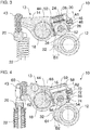
- the first rocker arm 14 has a first cam follower 24, a first actuating piston 26, two locking pistons 28 and a first actuating piston seat 30.
- the first cam follower 24 follows a cam contour of a first cam 32 of the camshaft 12.
- the first cam follower 24 is formed as a rotatably mounted roller.
- the first cam follower 24 is rotatable about a first cam follower axis 34.
- the first cam follower axis 34 is mounted in the first actuating piston 26.
- the first actuating piston 26 is displaceably mounted in the first actuating piston receptacle 30.
- An elastic element 36 for example a return spring, returns the first actuating piston 26 and thus the first cam follower 24 in one direction to the first cam 32.
- a displacement of the first actuating piston 26 can be blocked by the locking piston 28, as in FIG. 2 and FIG. 5 is shown.
- the first control piston 26 can be locked in the first control piston seat 30.
- the locking piston 28 are slidably mounted in the first actuating piston 26.
- the locking piston 28 are displaceable in a direction perpendicular to a displacement axis of the first actuating piston 26.
- the locking piston 28 can engage in a circumferential groove 38 of the first actuating piston receptacle 30. Engage the locking piston 28 in the circumferential groove 38, a displacement of the first actuating piston 26 is locked within the first actuating piston seat 30.
- the locking piston 28 are biased by elastic elements 40, for example return springs, in a locking position in which the locking piston 28 engage in the circumferential groove 38.
- a control fluid can be conducted to the peripheral groove 38 via one or more control fluid supply channels 42.
- the supplied control fluid causes the lockup pistons 28 to move in a direction toward each other.
- the locking piston 28 is disengaged from the circumferential groove 38. A displacement movement of the first actuating piston 26 is released.
- a cam contour of the first cam 32 is transmitted to the gas exchange valves 22 via the first cam follower 24.
- the first rocker arm 14 tilts about the rocker shaft 18 and actuated via a first adjusting screw 43, the valve bridge 20 for opening the gas exchange valves 22.
- a valve clearance can be adjusted and readjusted.
- the size of the clearance A1 may, for example, depend on an arrangement of the cam profiles of the two cams 32, 64 relative to each other.
- the control fluid supply passages 42 are supplied with control fluid via a main control fluid passage 44.
- the main control fluid passage 44 is formed as a lever axis longitudinal bore.
- rocker arms 14, 16 of the power transmission device 13 can be supplied with control fluid.
- rocker arms of other similarly or identically constructed power transmission devices may be supplied with control fluid from the main control fluid passage 44. This allows a simultaneous and common circuit of several power transmission devices, so that does not have to be switched cylinder-selective. This can significantly reduce the control effort.
- a first anti-rotation device 46 is provided.
- the displacement axis of the first actuating piston 26 coincides with a longitudinal axis of the first actuating piston receptacle 30.
- the first rotation lock 46 engages in a longitudinal groove 48 of the first actuating piston 26.
- the longitudinal groove 48 extends parallel to the longitudinal axis of the first actuating piston receptacle 30.
- the first rotation 46 only allows movement of the first actuating piston 26 along the longitudinal axis of the first actuating piston receptacle 30.
- the anti-rotation 46 in conjunction with the longitudinal groove 48 forms an axial stop for the first actuating piston 26.
- the first anti-rotation 46 may be formed, for example, pin-shaped or helical with tapered front end.
- a second anti-rotation device 50 is provided.
- the second anti-rotation device 50 is annular and arranged in a circumferential groove of the first actuating piston 26.
- the first cam follower axis 34 has a first lubricating fluid longitudinal passage 52.
- Lubricating fluid from the first lubricating fluid longitudinal passage 52 may be directed between the contact surfaces of the first cam follower 24 and the first cam follower axis 34 via a radial passage.
- the lubricating fluid longitudinal passage is connected to a lubricating fluid supply.
- the lubricating fluid supply is provided separately from the control fluid supply for supplying control fluid to the main control fluid passage 44.
- the second rocker arm 16 has a second cam follower 54, a second actuating piston 56 and a second actuating piston seat 58.
- the second rocker arm 16 is rigidly connected to the first rocker arm 14 via a second adjusting screw 60.
- the second set screw 60 is seated on a projection (tab) 62 of the first rocker arm 14.
- the projection 62 extends from a main body portion of the first rocker arm 14 in a direction parallel to the rocker shaft 18.
- the second cam follower 54 follows a cam contour of a second cam 64 of the camshaft 12.
- the second cam follower 54 is formed as a rotatably mounted roller.
- the second cam follower 54 is rotatable about a second cam follower axis 66.
- the second cam follower axis 66 is mounted in the second actuating piston 56.
- the second actuating piston 56 is displaceably mounted in the second actuating piston seat 58.
- control fluid can be supplied in a region (pressure chamber) 59 of the second actuating piston seat 58, which extends between a bottom surface of the second actuating piston seat 58 and the second actuating piston 56.
- the control fluid may be supplied via a control fluid supply channel 68.
- the control fluid supply channel 68 is in fluid communication with the main control fluid channel 44. If the pressure chamber is supplied with control fluid, a displacement of the second control piston 56 in the second control piston seat 58 is blocked. D. h., The second actuating piston 56 is locked in the second actuating piston receptacle 58. If the pressure chamber is not acted upon by control fluid, a displacement of the second actuating piston 56 in the second actuating piston receptacle 58 is released.
- a cam contour of the second cam 64 is compensated via a displacement of the second cam follower 54 within the second actuating piston seat 58.
- the cam contour of the second cam 64 is not transferred to the gas exchange valves 22.
- the second rocker arm 16 has an anti-rotation lock 70.
- the rotation lock 70 engages in a longitudinal groove 72 of the second actuating piston 56 in order to prevent rotation of the second actuating piston 56 about a longitudinal axis of the second actuating piston seat 58.
- the anti-rotation device 70 and the longitudinal groove 72 may be formed as the first anti-rotation 46 and the longitudinal groove 48.
- the anti-rotation device 70 in conjunction with the longitudinal groove 72 forms an axial stop for the second actuating piston 56.
- the second cam follower axis 66 has a lubricating fluid longitudinal passage 74 formed like the first lubricating fluid longitudinal passage 52 of the first cam follower axis 34.
- the locking piston 28 and the pressure chamber 59 can both be acted upon together with control fluid from the main control fluid passage 44.
- the power transmission device 13 can selectively transmit a cam contour of the first cam 32 or a cam contour of the second cam 64 to the gas exchange valves 22.
- control fluid is supplied via the main control fluid duct 44, a displacement of the first control piston 26 is released and a displacement of the second control piston 56 is blocked.
- the displacement of the first actuating piston 26 within the first actuating piston receptacle 30 compensates for the cam contour of the first cam 32.
- the blocking of the second actuating piston 56 leads to a transmission of the cam contour of the second cam 64 to the gas exchange valves 22.
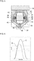
- the first cam 32 and the second cam 34 may be designed completely independently of each other. In order to control the gas exchange valves 22 are two independent Ventilhubkurven available as alternatives.
- the first cam 32 may be a normal lift cam, which causes a Ventilhubkurve C of the gas exchange valves 22.
- the gas exchange valves designed as inlet valves 22 are opened according to a gasoline or diesel cycle in the intake stroke.
- the second cam 64 may be formed as a Miller cam, which causes the valve lift curve D of the gas exchange valves 22.
- the gas exchange valves 22 designed as intake valves are closed earlier than in the case of the valve lift curve C.
- the cams 32, 64 can also be used to generate other valve lift curves.
Priority Applications (1)
| Application Number | Priority Date | Filing Date | Title |
|---|---|---|---|
| EP21175639.0A EP3892831A1 (fr) | 2017-08-18 | 2018-07-30 | Dispositif de transmission de force pour un mécanisme de distribution variable |
Applications Claiming Priority (1)
| Application Number | Priority Date | Filing Date | Title |
|---|---|---|---|
| DE102017118852.5A DE102017118852A1 (de) | 2017-08-18 | 2017-08-18 | Kraftübertragungsvorrichtung für variablen Ventiltrieb |
Related Child Applications (2)
| Application Number | Title | Priority Date | Filing Date |
|---|---|---|---|
| EP21175639.0A Division-Into EP3892831A1 (fr) | 2017-08-18 | 2018-07-30 | Dispositif de transmission de force pour un mécanisme de distribution variable |
| EP21175639.0A Division EP3892831A1 (fr) | 2017-08-18 | 2018-07-30 | Dispositif de transmission de force pour un mécanisme de distribution variable |
Publications (2)
| Publication Number | Publication Date |
|---|---|
| EP3444451A1 true EP3444451A1 (fr) | 2019-02-20 |
| EP3444451B1 EP3444451B1 (fr) | 2021-07-07 |
Family
ID=63103784
Family Applications (2)
| Application Number | Title | Priority Date | Filing Date |
|---|---|---|---|
| EP18186225.1A Active EP3444451B1 (fr) | 2017-08-18 | 2018-07-30 | Dispositif de transfert d'énergie pour un mécanisme de distribution variable |
| EP21175639.0A Pending EP3892831A1 (fr) | 2017-08-18 | 2018-07-30 | Dispositif de transmission de force pour un mécanisme de distribution variable |
Family Applications After (1)
| Application Number | Title | Priority Date | Filing Date |
|---|---|---|---|
| EP21175639.0A Pending EP3892831A1 (fr) | 2017-08-18 | 2018-07-30 | Dispositif de transmission de force pour un mécanisme de distribution variable |
Country Status (6)
| Country | Link |
|---|---|
| US (1) | US10895175B2 (fr) |
| EP (2) | EP3444451B1 (fr) |
| JP (1) | JP2019035411A (fr) |
| CN (2) | CN109404083B (fr) |
| BR (1) | BR102018016860B1 (fr) |
| DE (1) | DE102017118852A1 (fr) |
Cited By (3)
| Publication number | Priority date | Publication date | Assignee | Title |
|---|---|---|---|---|
| CN111520210A (zh) * | 2020-04-29 | 2020-08-11 | 施红 | 一种基于偏心滑槽传动原理的气门行程可调装置 |
| WO2021013718A1 (fr) * | 2019-07-23 | 2021-01-28 | Man Truck & Bus Se | Mécanisme de distribution variable pour un mode de freinage de moteur |
| WO2024002523A1 (fr) * | 2022-06-29 | 2024-01-04 | Eaton Intelligent Power Limited | Système de culbuteur avec agencement de butée côté came |
Families Citing this family (3)
| Publication number | Priority date | Publication date | Assignee | Title |
|---|---|---|---|---|
| DE102017118852A1 (de) * | 2017-08-18 | 2019-02-21 | Man Truck & Bus Ag | Kraftübertragungsvorrichtung für variablen Ventiltrieb |
| DE102017009541A1 (de) * | 2017-10-13 | 2019-04-18 | Daimler Ag | Ventiltrieb für eine Brennkraftmaschine eines Kraftfahrzeugs |
| EA202092392A2 (ru) * | 2020-07-16 | 2022-01-31 | Пауэрхаус Энджин Солюшнз Свитселанд АйПи Холдинг ГмбХ | Система двигателя внутреннего сгорания |
Citations (4)
| Publication number | Priority date | Publication date | Assignee | Title |
|---|---|---|---|---|
| JPS57182205U (fr) * | 1981-05-15 | 1982-11-18 | ||
| JPS61105706U (fr) * | 1984-12-17 | 1986-07-04 | ||
| FR2709149A1 (fr) * | 1992-10-16 | 1995-02-24 | Picchi Jean Pierre | Dispositif de commande de levée et temps d'ouverture variable d'une soupape. |
| US20150159521A1 (en) * | 2013-12-05 | 2015-06-11 | Jacobs Vehicle Systems, Inc. | Apparatus and system comprising collapsing and extending mechanisms for actuating engine valves |
Family Cites Families (26)
| Publication number | Priority date | Publication date | Assignee | Title |
|---|---|---|---|---|
| DE3613945A1 (de) * | 1985-04-26 | 1986-10-30 | Mazda Motor Corp., Hiroshima | Veraenderbarer ventilmechanismus fuer verbrennungsmaschinen |
| JP2814613B2 (ja) * | 1989-10-12 | 1998-10-27 | 日産自動車株式会社 | エンジンの弁作動装置 |
| DE4025569C1 (en) | 1990-08-11 | 1991-07-18 | Mercedes-Benz Aktiengesellschaft, 7000 Stuttgart, De | Valve brake for vehicle IC engine - has separately controllable cylinder outlet valves for drive and braking functions |
| JPH04109010A (ja) * | 1990-08-27 | 1992-04-10 | Ntn Corp | 可変バルブタイミング装置 |
| DE4335431A1 (de) * | 1992-11-13 | 1995-04-20 | Iav Motor Gmbh | Schaltbarer Ventiltrieb mit Kipphebel und unterliegender Nockenwelle für Gaswechselventile für Verbrennungsmotoren |
| DE4324756C2 (de) * | 1993-07-23 | 1997-06-12 | Iav Motor Gmbh | Verdrehsicherung für einen Ventilstößel |
| JPH09105317A (ja) * | 1995-10-12 | 1997-04-22 | Unisia Jecs Corp | エンジンの弁作動装置 |
| DE19914046A1 (de) * | 1999-03-27 | 2000-09-28 | Schaeffler Waelzlager Ohg | Als Kipp- oder Schwinghebel ausgebildeter Nockenfolger eines Ventiltriebs einer Brennkraftmaschine |
| US6499451B1 (en) * | 2001-12-17 | 2002-12-31 | Delphi Technologies, Inc. | Control system for variable activation of intake valves in an internal combustion engine |
| DE10303567A1 (de) | 2003-01-30 | 2004-08-12 | Daimlerchrysler Ag | Hydraulischer Mitnehmerkipphebel |
| US7086360B1 (en) * | 2003-02-27 | 2006-08-08 | Ina-Schaeffler Kg | Assembly and torsional stop device for roller tappets of a drive in an internal combustion engine |
| JP4117481B2 (ja) * | 2003-11-13 | 2008-07-16 | 三菱自動車工業株式会社 | 内燃機関の可変動弁装置 |
| WO2006002757A1 (fr) * | 2004-07-01 | 2006-01-12 | Schaeffler Kg | Galet de came commutable |
| DE102006034951A1 (de) | 2005-08-22 | 2007-03-29 | Schaeffler Kg | Ventiltrieb für eine Brennkraftmaschine |
| US8267057B2 (en) * | 2007-08-15 | 2012-09-18 | Advanced Racing Systems, Inc. | Continuously variable valve lift for internal combustion engine |
| US7913656B2 (en) * | 2007-10-31 | 2011-03-29 | Ford Global Technologies, Llc | Variable displacement engine having selectively engageable rocker arm with positioning device |
| US8161929B2 (en) * | 2007-11-21 | 2012-04-24 | Schaeffler Kg | Switchable tappet |
| EP2487341B1 (fr) * | 2009-10-06 | 2014-12-10 | Yamaha Hatsudoki Kabushiki Kaisha | Dispositif de commande de soupape pour moteur |
| DE102010011828A1 (de) * | 2010-03-18 | 2011-09-22 | Schaeffler Technologies Gmbh & Co. Kg | Schaltbarer Hebel für einen Ventiltrieb einer Brennkraftmaschine |
| KR101171912B1 (ko) * | 2010-11-29 | 2012-08-07 | 기아자동차주식회사 | 밸브브릿지 일체형 가변 밸브 액츄에이터 |
| US9163566B2 (en) * | 2011-07-06 | 2015-10-20 | Volvo Trucks AB | Valve actuation mechanism and automotive vehicle comprising such a valve actuation mechanism |
| DE102012208238A1 (de) * | 2012-05-16 | 2013-11-21 | Schaeffler Technologies AG & Co. KG | Ventiltriebsbetätigungseinrichtung für eine Brennkraftmaschine |
| EP2975230B1 (fr) * | 2014-07-15 | 2018-02-21 | Jacobs Vehicle Systems, Inc. | Systèmes d'actionnement de soupape à mouvement perdu avec des éléments de verrouillage comprenant des éléments de verrouillage en forme de coin |
| WO2016059456A1 (fr) * | 2014-10-15 | 2016-04-21 | Shanghai Universoon Auto Parts Co., Ltd. | Procédé et système de freinage moteur |
| US10941680B2 (en) * | 2015-12-28 | 2021-03-09 | Eaton Corporation | Discrete variable valve lift engine systems and methods |
| DE102017118852A1 (de) * | 2017-08-18 | 2019-02-21 | Man Truck & Bus Ag | Kraftübertragungsvorrichtung für variablen Ventiltrieb |
-
2017
- 2017-08-18 DE DE102017118852.5A patent/DE102017118852A1/de not_active Withdrawn
-
2018
- 2018-07-30 EP EP18186225.1A patent/EP3444451B1/fr active Active
- 2018-07-30 EP EP21175639.0A patent/EP3892831A1/fr active Pending
- 2018-08-15 CN CN201810928002.5A patent/CN109404083B/zh active Active
- 2018-08-15 CN CN202210271801.6A patent/CN114893272A/zh active Pending
- 2018-08-17 US US16/104,507 patent/US10895175B2/en active Active
- 2018-08-17 BR BR102018016860-6A patent/BR102018016860B1/pt active IP Right Grant
- 2018-08-20 JP JP2018153796A patent/JP2019035411A/ja active Pending
Patent Citations (4)
| Publication number | Priority date | Publication date | Assignee | Title |
|---|---|---|---|---|
| JPS57182205U (fr) * | 1981-05-15 | 1982-11-18 | ||
| JPS61105706U (fr) * | 1984-12-17 | 1986-07-04 | ||
| FR2709149A1 (fr) * | 1992-10-16 | 1995-02-24 | Picchi Jean Pierre | Dispositif de commande de levée et temps d'ouverture variable d'une soupape. |
| US20150159521A1 (en) * | 2013-12-05 | 2015-06-11 | Jacobs Vehicle Systems, Inc. | Apparatus and system comprising collapsing and extending mechanisms for actuating engine valves |
Cited By (5)
| Publication number | Priority date | Publication date | Assignee | Title |
|---|---|---|---|---|
| WO2021013718A1 (fr) * | 2019-07-23 | 2021-01-28 | Man Truck & Bus Se | Mécanisme de distribution variable pour un mode de freinage de moteur |
| CN114096743A (zh) * | 2019-07-23 | 2022-02-25 | 曼卡车和巴士欧洲股份公司 | 用于发动机制动模式的可变气门机构 |
| CN111520210A (zh) * | 2020-04-29 | 2020-08-11 | 施红 | 一种基于偏心滑槽传动原理的气门行程可调装置 |
| CN111520210B (zh) * | 2020-04-29 | 2021-05-28 | 江苏赛耐气门有限公司 | 一种基于偏心滑槽传动原理的气门行程可调装置 |
| WO2024002523A1 (fr) * | 2022-06-29 | 2024-01-04 | Eaton Intelligent Power Limited | Système de culbuteur avec agencement de butée côté came |
Also Published As
| Publication number | Publication date |
|---|---|
| RU2018130005A3 (fr) | 2022-01-12 |
| CN114893272A (zh) | 2022-08-12 |
| BR102018016860A8 (pt) | 2023-02-14 |
| DE102017118852A1 (de) | 2019-02-21 |
| BR102018016860A2 (pt) | 2019-03-26 |
| US20190055858A1 (en) | 2019-02-21 |
| RU2018130005A (ru) | 2020-02-17 |
| JP2019035411A (ja) | 2019-03-07 |
| EP3444451B1 (fr) | 2021-07-07 |
| CN109404083B (zh) | 2022-03-08 |
| BR102018016860B1 (pt) | 2023-05-16 |
| EP3892831A1 (fr) | 2021-10-13 |
| US10895175B2 (en) | 2021-01-19 |
| CN109404083A (zh) | 2019-03-01 |
Similar Documents
| Publication | Publication Date | Title |
|---|---|---|
| EP3444451B1 (fr) | Dispositif de transfert d'énergie pour un mécanisme de distribution variable | |
| EP3170997B1 (fr) | Commande de soupape variable comprenant un culbuteur | |
| EP1807609B1 (fr) | Mecanisme de commande de soupape de moteur a combustion interne | |
| DE10348367A1 (de) | Kompakte zweistufige Kipphebelanordnung | |
| EP1907673A1 (fr) | Mecanisme de commande de soupape pour un moteur a combustion interne | |
| DE19908286B4 (de) | Variable Ventilsteuerung für Brennkraftmaschinen | |
| EP3385513B1 (fr) | Commande de soupape variable | |
| EP2764229A1 (fr) | Ensemble piston pour une chambre de combustion présentant un taux de compression variable, d'un moteur à combustion interne | |
| EP3434871B1 (fr) | Système de cames coulissantes | |
| EP0779411B1 (fr) | Commande de soupape pour moteur à combustion interne | |
| EP0634564B1 (fr) | Dispositif de désactivation de soupape de moteur à combustion interne | |
| DE4408808A1 (de) | Ventiltrieb mit einem unwirksamschaltbaren oder zwei alternativ wirksamschaltbaren Nocken für Ladungswechselventile von Brennkraftmaschinen | |
| EP3418513B1 (fr) | Dispositif de transmission de force | |
| DE102017217500A1 (de) | Längenverstellbares Pleuel mit mechanischer Verstellung | |
| DE112021002178T5 (de) | Kipphebel | |
| WO2012175070A1 (fr) | Levier basculant et moteur à combustion interne pourvu d'un tel levier | |
| DE102007052251A1 (de) | Ventiltriebvorrichtung | |
| DE10311069B3 (de) | Vorrichtung zum Verstellen der Hubfunktion eines Ladungswechselventils einer Kolbenbrennkraftmaschine | |
| EP1588027B1 (fr) | Culbuteur d'entrainement hydraulique | |
| WO2018185197A1 (fr) | Dispositif d'actionnement mécanique de soupapes | |
| DE102015213627B3 (de) | Hydraulikelement mit Motorbremsfunktion für eine Viertakthubkolbenbrennkraftmaschine und Viertakthubkolbenbrennkraftmaschine | |
| DE102017205814A1 (de) | Mechanische Ventilbetätigungsvorrichtung | |
| EP3564502B1 (fr) | Commande de soupape variable | |
| EP3173593A1 (fr) | Commande de soupape variable comprenant un culbuteur | |
| DE102008047501A1 (de) | Schaltvorrichtung und Schaltanordnung für eine Brennkraftmaschine |
Legal Events
| Date | Code | Title | Description |
|---|---|---|---|
| PUAI | Public reference made under article 153(3) epc to a published international application that has entered the european phase |
Free format text: ORIGINAL CODE: 0009012 |
|
| STAA | Information on the status of an ep patent application or granted ep patent |
Free format text: STATUS: THE APPLICATION HAS BEEN PUBLISHED |
|
| AK | Designated contracting states |
Kind code of ref document: A1 Designated state(s): AL AT BE BG CH CY CZ DE DK EE ES FI FR GB GR HR HU IE IS IT LI LT LU LV MC MK MT NL NO PL PT RO RS SE SI SK SM TR |
|
| AX | Request for extension of the european patent |
Extension state: BA ME |
|
| RAP1 | Party data changed (applicant data changed or rights of an application transferred) |
Owner name: MAN TRUCK & BUS SE |
|
| STAA | Information on the status of an ep patent application or granted ep patent |
Free format text: STATUS: REQUEST FOR EXAMINATION WAS MADE |
|
| 17P | Request for examination filed |
Effective date: 20190819 |
|
| RBV | Designated contracting states (corrected) |
Designated state(s): AL AT BE BG CH CY CZ DE DK EE ES FI FR GB GR HR HU IE IS IT LI LT LU LV MC MK MT NL NO PL PT RO RS SE SI SK SM TR |
|
| STAA | Information on the status of an ep patent application or granted ep patent |
Free format text: STATUS: EXAMINATION IS IN PROGRESS |
|
| 17Q | First examination report despatched |
Effective date: 20200221 |
|
| STAA | Information on the status of an ep patent application or granted ep patent |
Free format text: STATUS: EXAMINATION IS IN PROGRESS |
|
| GRAP | Despatch of communication of intention to grant a patent |
Free format text: ORIGINAL CODE: EPIDOSNIGR1 |
|
| STAA | Information on the status of an ep patent application or granted ep patent |
Free format text: STATUS: GRANT OF PATENT IS INTENDED |
|
| INTG | Intention to grant announced |
Effective date: 20210223 |
|
| GRAS | Grant fee paid |
Free format text: ORIGINAL CODE: EPIDOSNIGR3 |
|
| GRAA | (expected) grant |
Free format text: ORIGINAL CODE: 0009210 |
|
| STAA | Information on the status of an ep patent application or granted ep patent |
Free format text: STATUS: THE PATENT HAS BEEN GRANTED |
|
| AK | Designated contracting states |
Kind code of ref document: B1 Designated state(s): AL AT BE BG CH CY CZ DE DK EE ES FI FR GB GR HR HU IE IS IT LI LT LU LV MC MK MT NL NO PL PT RO RS SE SI SK SM TR |
|
| REG | Reference to a national code |
Ref country code: GB Ref legal event code: FG4D Free format text: NOT ENGLISH |
|
| REG | Reference to a national code |
Ref country code: AT Ref legal event code: REF Ref document number: 1408787 Country of ref document: AT Kind code of ref document: T Effective date: 20210715 |
|
| REG | Reference to a national code |
Ref country code: DE Ref legal event code: R096 Ref document number: 502018005983 Country of ref document: DE |
|
| REG | Reference to a national code |
Ref country code: IE Ref legal event code: FG4D Free format text: LANGUAGE OF EP DOCUMENT: GERMAN |
|
| REG | Reference to a national code |
Ref country code: NL Ref legal event code: FP |
|
| REG | Reference to a national code |
Ref country code: SE Ref legal event code: TRGR |
|
| REG | Reference to a national code |
Ref country code: LT Ref legal event code: MG9D |
|
| PG25 | Lapsed in a contracting state [announced via postgrant information from national office to epo] |
Ref country code: LT Free format text: LAPSE BECAUSE OF FAILURE TO SUBMIT A TRANSLATION OF THE DESCRIPTION OR TO PAY THE FEE WITHIN THE PRESCRIBED TIME-LIMIT Effective date: 20210707 Ref country code: BG Free format text: LAPSE BECAUSE OF FAILURE TO SUBMIT A TRANSLATION OF THE DESCRIPTION OR TO PAY THE FEE WITHIN THE PRESCRIBED TIME-LIMIT Effective date: 20211007 Ref country code: NO Free format text: LAPSE BECAUSE OF FAILURE TO SUBMIT A TRANSLATION OF THE DESCRIPTION OR TO PAY THE FEE WITHIN THE PRESCRIBED TIME-LIMIT Effective date: 20211007 Ref country code: PT Free format text: LAPSE BECAUSE OF FAILURE TO SUBMIT A TRANSLATION OF THE DESCRIPTION OR TO PAY THE FEE WITHIN THE PRESCRIBED TIME-LIMIT Effective date: 20211108 Ref country code: RS Free format text: LAPSE BECAUSE OF FAILURE TO SUBMIT A TRANSLATION OF THE DESCRIPTION OR TO PAY THE FEE WITHIN THE PRESCRIBED TIME-LIMIT Effective date: 20210707 Ref country code: HR Free format text: LAPSE BECAUSE OF FAILURE TO SUBMIT A TRANSLATION OF THE DESCRIPTION OR TO PAY THE FEE WITHIN THE PRESCRIBED TIME-LIMIT Effective date: 20210707 Ref country code: ES Free format text: LAPSE BECAUSE OF FAILURE TO SUBMIT A TRANSLATION OF THE DESCRIPTION OR TO PAY THE FEE WITHIN THE PRESCRIBED TIME-LIMIT Effective date: 20210707 Ref country code: FI Free format text: LAPSE BECAUSE OF FAILURE TO SUBMIT A TRANSLATION OF THE DESCRIPTION OR TO PAY THE FEE WITHIN THE PRESCRIBED TIME-LIMIT Effective date: 20210707 |
|
| PG25 | Lapsed in a contracting state [announced via postgrant information from national office to epo] |
Ref country code: PL Free format text: LAPSE BECAUSE OF FAILURE TO SUBMIT A TRANSLATION OF THE DESCRIPTION OR TO PAY THE FEE WITHIN THE PRESCRIBED TIME-LIMIT Effective date: 20210707 Ref country code: LV Free format text: LAPSE BECAUSE OF FAILURE TO SUBMIT A TRANSLATION OF THE DESCRIPTION OR TO PAY THE FEE WITHIN THE PRESCRIBED TIME-LIMIT Effective date: 20210707 Ref country code: GR Free format text: LAPSE BECAUSE OF FAILURE TO SUBMIT A TRANSLATION OF THE DESCRIPTION OR TO PAY THE FEE WITHIN THE PRESCRIBED TIME-LIMIT Effective date: 20211008 |
|
| REG | Reference to a national code |
Ref country code: CH Ref legal event code: PL |
|
| REG | Reference to a national code |
Ref country code: BE Ref legal event code: MM Effective date: 20210731 |
|
| REG | Reference to a national code |
Ref country code: DE Ref legal event code: R097 Ref document number: 502018005983 Country of ref document: DE |
|
| PG25 | Lapsed in a contracting state [announced via postgrant information from national office to epo] |
Ref country code: LI Free format text: LAPSE BECAUSE OF NON-PAYMENT OF DUE FEES Effective date: 20210731 Ref country code: DK Free format text: LAPSE BECAUSE OF FAILURE TO SUBMIT A TRANSLATION OF THE DESCRIPTION OR TO PAY THE FEE WITHIN THE PRESCRIBED TIME-LIMIT Effective date: 20210707 Ref country code: CH Free format text: LAPSE BECAUSE OF NON-PAYMENT OF DUE FEES Effective date: 20210731 |
|
| PLBE | No opposition filed within time limit |
Free format text: ORIGINAL CODE: 0009261 |
|
| STAA | Information on the status of an ep patent application or granted ep patent |
Free format text: STATUS: NO OPPOSITION FILED WITHIN TIME LIMIT |
|
| PG25 | Lapsed in a contracting state [announced via postgrant information from national office to epo] |
Ref country code: SM Free format text: LAPSE BECAUSE OF FAILURE TO SUBMIT A TRANSLATION OF THE DESCRIPTION OR TO PAY THE FEE WITHIN THE PRESCRIBED TIME-LIMIT Effective date: 20210707 Ref country code: SK Free format text: LAPSE BECAUSE OF FAILURE TO SUBMIT A TRANSLATION OF THE DESCRIPTION OR TO PAY THE FEE WITHIN THE PRESCRIBED TIME-LIMIT Effective date: 20210707 Ref country code: RO Free format text: LAPSE BECAUSE OF FAILURE TO SUBMIT A TRANSLATION OF THE DESCRIPTION OR TO PAY THE FEE WITHIN THE PRESCRIBED TIME-LIMIT Effective date: 20210707 Ref country code: MC Free format text: LAPSE BECAUSE OF FAILURE TO SUBMIT A TRANSLATION OF THE DESCRIPTION OR TO PAY THE FEE WITHIN THE PRESCRIBED TIME-LIMIT Effective date: 20210707 Ref country code: LU Free format text: LAPSE BECAUSE OF NON-PAYMENT OF DUE FEES Effective date: 20210730 Ref country code: EE Free format text: LAPSE BECAUSE OF FAILURE TO SUBMIT A TRANSLATION OF THE DESCRIPTION OR TO PAY THE FEE WITHIN THE PRESCRIBED TIME-LIMIT Effective date: 20210707 Ref country code: CZ Free format text: LAPSE BECAUSE OF FAILURE TO SUBMIT A TRANSLATION OF THE DESCRIPTION OR TO PAY THE FEE WITHIN THE PRESCRIBED TIME-LIMIT Effective date: 20210707 Ref country code: AL Free format text: LAPSE BECAUSE OF FAILURE TO SUBMIT A TRANSLATION OF THE DESCRIPTION OR TO PAY THE FEE WITHIN THE PRESCRIBED TIME-LIMIT Effective date: 20210707 |
|
| 26N | No opposition filed |
Effective date: 20220408 |
|
| PG25 | Lapsed in a contracting state [announced via postgrant information from national office to epo] |
Ref country code: IE Free format text: LAPSE BECAUSE OF NON-PAYMENT OF DUE FEES Effective date: 20210730 Ref country code: BE Free format text: LAPSE BECAUSE OF NON-PAYMENT OF DUE FEES Effective date: 20210731 |
|
| PGFP | Annual fee paid to national office [announced via postgrant information from national office to epo] |
Ref country code: SE Payment date: 20230317 Year of fee payment: 6 |
|
| PG25 | Lapsed in a contracting state [announced via postgrant information from national office to epo] |
Ref country code: CY Free format text: LAPSE BECAUSE OF FAILURE TO SUBMIT A TRANSLATION OF THE DESCRIPTION OR TO PAY THE FEE WITHIN THE PRESCRIBED TIME-LIMIT Effective date: 20210707 |
|
| PG25 | Lapsed in a contracting state [announced via postgrant information from national office to epo] |
Ref country code: HU Free format text: LAPSE BECAUSE OF FAILURE TO SUBMIT A TRANSLATION OF THE DESCRIPTION OR TO PAY THE FEE WITHIN THE PRESCRIBED TIME-LIMIT; INVALID AB INITIO Effective date: 20180730 |
|
| PGFP | Annual fee paid to national office [announced via postgrant information from national office to epo] |
Ref country code: NL Payment date: 20230726 Year of fee payment: 6 |
|
| PGFP | Annual fee paid to national office [announced via postgrant information from national office to epo] |
Ref country code: IT Payment date: 20230721 Year of fee payment: 6 Ref country code: GB Payment date: 20230725 Year of fee payment: 6 |
|
| PGFP | Annual fee paid to national office [announced via postgrant information from national office to epo] |
Ref country code: FR Payment date: 20230725 Year of fee payment: 6 Ref country code: DE Payment date: 20230726 Year of fee payment: 6 |