EP3444408B1 - Wc mit spülwasseranschluss - Google Patents
Wc mit spülwasseranschluss Download PDFInfo
- Publication number
- EP3444408B1 EP3444408B1 EP17020366.5A EP17020366A EP3444408B1 EP 3444408 B1 EP3444408 B1 EP 3444408B1 EP 17020366 A EP17020366 A EP 17020366A EP 3444408 B1 EP3444408 B1 EP 3444408B1
- Authority
- EP
- European Patent Office
- Prior art keywords
- toilet
- flushing water
- connection
- pipe section
- pipe
- Prior art date
- Legal status (The legal status is an assumption and is not a legal conclusion. Google has not performed a legal analysis and makes no representation as to the accuracy of the status listed.)
- Active
Links
- 238000011010 flushing procedure Methods 0.000 title claims description 101
- XLYOFNOQVPJJNP-UHFFFAOYSA-N water Substances O XLYOFNOQVPJJNP-UHFFFAOYSA-N 0.000 title claims description 96
- 239000000919 ceramic Substances 0.000 claims description 15
- 238000005266 casting Methods 0.000 claims description 5
- 238000000605 extraction Methods 0.000 claims description 5
- 239000000654 additive Substances 0.000 claims description 4
- 238000004140 cleaning Methods 0.000 claims description 3
- 238000000034 method Methods 0.000 claims description 3
- 239000000645 desinfectant Substances 0.000 claims description 2
- 238000003780 insertion Methods 0.000 claims 1
- 230000037431 insertion Effects 0.000 claims 1
- 239000002351 wastewater Substances 0.000 description 7
- 238000009434 installation Methods 0.000 description 6
- 230000007704 transition Effects 0.000 description 6
- 230000008901 benefit Effects 0.000 description 4
- 238000004519 manufacturing process Methods 0.000 description 4
- 235000019645 odor Nutrition 0.000 description 4
- 239000000463 material Substances 0.000 description 3
- 125000002066 L-histidyl group Chemical group [H]N1C([H])=NC(C([H])([H])[C@](C(=O)[*])([H])N([H])[H])=C1[H] 0.000 description 1
- 230000006978 adaptation Effects 0.000 description 1
- 238000013459 approach Methods 0.000 description 1
- 238000005253 cladding Methods 0.000 description 1
- 239000012459 cleaning agent Substances 0.000 description 1
- 238000011109 contamination Methods 0.000 description 1
- 230000001419 dependent effect Effects 0.000 description 1
- 238000001035 drying Methods 0.000 description 1
- 229920001971 elastomer Polymers 0.000 description 1
- 239000000806 elastomer Substances 0.000 description 1
- 230000002349 favourable effect Effects 0.000 description 1
- 238000010304 firing Methods 0.000 description 1
- 230000008569 process Effects 0.000 description 1
- 230000009467 reduction Effects 0.000 description 1
- 239000008237 rinsing water Substances 0.000 description 1
- 239000010865 sewage Substances 0.000 description 1
- 238000004659 sterilization and disinfection Methods 0.000 description 1
Images


Classifications
-
- E—FIXED CONSTRUCTIONS
- E03—WATER SUPPLY; SEWERAGE
- E03D—WATER-CLOSETS OR URINALS WITH FLUSHING DEVICES; FLUSHING VALVES THEREFOR
- E03D11/00—Other component parts of water-closets, e.g. noise-reducing means in the flushing system, flushing pipes mounted in the bowl, seals for the bowl outlet, devices preventing overflow of the bowl contents; devices forming a water seal in the bowl after flushing, devices eliminating obstructions in the bowl outlet or preventing backflow of water and excrements from the waterpipe
- E03D11/02—Water-closet bowls ; Bowls with a double odour seal optionally with provisions for a good siphonic action; siphons as part of the bowl
- E03D11/08—Bowls with means producing a flushing water swirl
-
- E—FIXED CONSTRUCTIONS
- E03—WATER SUPPLY; SEWERAGE
- E03D—WATER-CLOSETS OR URINALS WITH FLUSHING DEVICES; FLUSHING VALVES THEREFOR
- E03D1/00—Water flushing devices with cisterns ; Setting up a range of flushing devices or water-closets; Combinations of several flushing devices
- E03D1/38—Adaptations or arrangements of flushing pipes
-
- E—FIXED CONSTRUCTIONS
- E03—WATER SUPPLY; SEWERAGE
- E03D—WATER-CLOSETS OR URINALS WITH FLUSHING DEVICES; FLUSHING VALVES THEREFOR
- E03D11/00—Other component parts of water-closets, e.g. noise-reducing means in the flushing system, flushing pipes mounted in the bowl, seals for the bowl outlet, devices preventing overflow of the bowl contents; devices forming a water seal in the bowl after flushing, devices eliminating obstructions in the bowl outlet or preventing backflow of water and excrements from the waterpipe
- E03D11/13—Parts or details of bowls; Special adaptations of pipe joints or couplings for use with bowls, e.g. provisions in bowl construction preventing backflow of waste-water from the bowl in the flushing pipe or cistern, provisions for a secondary flushing, for noise-reducing
- E03D11/14—Means for connecting the bowl to the wall, e.g. to a wall outlet
-
- E—FIXED CONSTRUCTIONS
- E03—WATER SUPPLY; SEWERAGE
- E03D—WATER-CLOSETS OR URINALS WITH FLUSHING DEVICES; FLUSHING VALVES THEREFOR
- E03D9/00—Sanitary or other accessories for lavatories ; Devices for cleaning or disinfecting the toilet room or the toilet bowl; Devices for eliminating smells
- E03D9/08—Devices in the bowl producing upwardly-directed sprays; Modifications of the bowl for use with such devices ; Bidets; Combinations of bowls with urinals or bidets; Hot-air or other devices mounted in or on the bowl, urinal or bidet for cleaning or disinfecting
-
- E—FIXED CONSTRUCTIONS
- E03—WATER SUPPLY; SEWERAGE
- E03D—WATER-CLOSETS OR URINALS WITH FLUSHING DEVICES; FLUSHING VALVES THEREFOR
- E03D9/00—Sanitary or other accessories for lavatories ; Devices for cleaning or disinfecting the toilet room or the toilet bowl; Devices for eliminating smells
- E03D9/16—Water pressure regulating means in flushing pipes
Definitions
- the present invention relates to a flushing toilet, or toilet for short, which accordingly has a flushing water connection, and its use.
- Toilets have been standard and widespread for a long time. In accordance with their function, they have a connection for flushing water that comes from a flushing water supply, for example a cistern or a flushing water line without a cistern, but with a flush valve.
- a vertical piece of pipe regularly leads down from the cistern to a so-called flushing bend, in which the line direction is changed by about 90 degrees towards the toilet. If there is no cistern, a corresponding flushing water line can run horizontally in a wall behind the toilet and can also be reached via a flushing arch (i.e. a corner piece).
- a toilet essentially consists of a toilet body, often made of ceramic.
- the toilet body regularly has a rear side with which it is moved towards an installation wall. With hanging installation, the back of the toilet body hangs on the wall; but it can also have its own stand.
- the connections are regularly made via the rear, for which the toilet body has corresponding connection stubs for the flushing water and of course for the waste water on the rear.
- the installer connects these connecting pieces, which are regularly integrated in the ceramic body, to e.g. the flushing elbow and a wall-side waste water connection, i.e. access to the sewer system.
- the flushing water supplied through the flushing water connection is conventionally distributed along a flushing rim into the toilet bowl.
- the flushing rim is designed to overhang inward along an upper rim of the toilet bowl and distributes the rinse water through a plurality of downwardly directed openings similar to a shower head.
- flush water inlet opening or a few such openings
- Such flushing water inlet openings are often not provided at the rear, but rather at the side.
- the flushing water is usually guided along a curved pipe to the flushing water inlet opening, which can be designed to be integrated with the toilet body and, analogous to the conventional toilets described above, leads to a connecting piece on the back of the toilet, i.e. at the wall level .
- EP 2 993 247 A1 shows all generic toilets with a central rear integrated flushing water connection which, as evidenced by the figures, lies at a small distance from the rear of the toilet body itself.
- the connections open into chambers in the toilet body, from which further flushing water lines then branch off transversely into the toilet body.
- the EP 3 064 663 A1 shows an integrated flushing water connection arranged next to a toilet bowl, to which a longer and curved plastic pipe leads, into which a flow throttle and a secondary chamber for odor extraction are integrated and which accomplishes a cross-sectional shape adaptation from a round to an elongated upright cross-section.
- the invention is based on the problem of specifying a toilet that is improved with regard to the flushing water connection.
- a toilet with a toilet body, a toilet bowl in the toilet body, a flush water inlet opening in the toilet bowl of the toilet body, a line integrated in the toilet body between the flush water inlet opening and an integrated flush water connection of the toilet, a pipe section separate from the toilet body for connection to the flushing water connection of the toilet and connection of the same to a flushing water supply for the toilet, the flushing water connection being arranged behind the toilet bowl, the flushing water connection at a distance of at least 10 cm in front the rear of the toilet body is provided, and the line pipe section is provided flexibly in favor of height adjustability or multiple in favor of height adjustability with different height offset, as well as through its advantageous use.
- an intermediate distance is provided between an integrated flushing water connection of the toilet and the rear of the toilet body. This is at least 10 cm.
- the flushing water connection is understood to mean the connection to the toilet body itself, that is to say to a line piece that is on the one hand in the toilet body is integrated and on the other hand leads from the flushing water connection to the flushing water inlet opening (into the toilet bowl).
- the distance is bridged when connecting using a corresponding piece of pipe, which will be discussed in more detail below.
- This is then not integrated with the toilet body and can also consist of a different material.
- the flushing water connection is preferably not connected to the rear of the toilet body.
- a certain volume of technical equipment for the shower function and other functions must be accommodated there between the back of the toilet bowl itself and the back of the toilet body and / or above this area, so that the distance between the back of the bowl and the back of the toilet body is regularly larger is less than for simple toilets without additional functions.
- the pipe section can, however, for. B. made of plastic.
- the line described between the flushing water inlet opening and the flushing water connection can be implemented using the so-called hollow casting process.
- Integrated means that they are manufactured in the same material and in a uniform manufacturing process. As a rule, there are no visible borders or material transitions.
- connection piece When producing a ceramic toilet body with a ceramic line for the flushing water that is routed conventionally to the back of the toilet body, the corresponding connection piece is usually connected to other ceramic parts on the back, in particular to a frame of the toilet body.
- the inventors have found a somewhat increased frequency of cracks, which can be caused during the ceramic production (including firing and drying), but also during the mechanical stress caused by the weight of the user afterwards. In any case, it has proven to be problematic to use the line piece for the flushing water as a kind of "lever" for introducing force to the rear of the toilet body.
- this piece makes the production of the toilet body unnecessarily more complex, whether it is made of plastic or ceramic.
- the invention is also particularly suitable for the toilets already mentioned at the beginning without a classic flushing rim, but with a lateral flushing water inlet opening in the toilet bowl.
- the pipe bend connecting this flushing water inlet opening to the flushing water connection is made integrated with the toilet body, in particular in ceramic and in particular with the hollow casting process already mentioned. Over the length of this pipe bend, there are then no further transitions between separate pieces with jumps in diameter, glued joints, seals or similar elements that impede the flow, offer approaches to contamination problems, increase manufacturing costs, harbor the risk of leaks and / or complicate assembly.
- the flushing water connection is (and quite generally in this invention), preferably in the middle with respect to the width direction, that is, centrally behind the toilet bowl. In the case just described with the pipe bend, this leads not only behind the toilet bowl, but also into an area behind its center, cf. the embodiment.
- the flushing water connection itself can again have a circular cross section even in the case of pipe bends that regularly have a non-round (e.g. oval) cross section.
- Conventional connection techniques in particular a circular sleeve on the side of the flushing water connection of the toilet and an inserted pipe end with a conventional seal, can thus be used.
- non-round cross-sections e.g. B. glued, which is comparatively more complex and less reliable.
- Another advantage that can be achieved with the invention is a reduction in the number of line connections or individual parts required on line sections, namely by making the line pipe section to be connected (or connected) to the flushing water connection of the toilet relatively long. During installation, it can then extend beyond the toilet body to the rear and connected to the flushing water supply within the wall, i.e. behind the front of the wall will. For example, it can be connected directly to the flushing elbow. Conventionally, if the line part executed integrated with the toilet body did not reach the back of the toilet anyway, especially if a curved line bend along the toilet bowl was not integrated, this line bend z. B. realized in plastic. In turn, a straight piece of pipe was led forward from the flushing elbow and cut to length. By pulling the pipe section to be connected to the (integrated) flushing water connection of the toilet into the wall, the number of pipe sections and the number of transitions can be reduced.
- One aspect of the invention consists in a height adaptability of the flushing water connection, in that the line pipe section is provided flexibly in favor of height adaptability or is provided several times with different height offset in favor of height adaptability.
- the height can be adjusted by choosing between a plurality of differently shaped pipe sections. This means that a difference in height can be compensated for depending on the individual case. If the toilet is to be mounted with a height to be selected from a certain adjustment range, the mechanical fastenings can e.g. B. be carried out with elongated holes.
- the waste water connection is already height-adjustable on the wall side or can be solved in a height-adjustable manner analogous to the flushing water connection.
- connection opening z. B. generally provided and with a z. B. be provided screwable cover.
- the connection opening can then be used z. B. by installing a flushing water throttle.
- a flushing water throttle can adapt the flushing water flow to individual situations if the flushing water may be too kinetic due to a certain predetermined gradient to the cistern or a predetermined line pressure Energy flows in. This can be an advantage, especially in toilets with the already mentioned multiple flush water inlet opening in the bowl. especially to prevent splashing out.
- EP 3 064 663 A1 for an explanation, reference is made to EP 3 064 663 A1 .
- an odor extraction device can be connected in order to extract disruptive odors from the toilet bowl via the flushing water line.
- additives can be introduced, e.g. B. a device for introducing cleaning or disinfecting agents (for example in tablet form) can be used through the connection opening, z. B. a cage.
- a further advantage of the invention can result if the pipe section in the rear area of the toilet is thinner-walled than a corresponding ceramic pipe section due to its plastic design, thus saving valuable space.
- This place can z. B. can be used for the installation of shower equipment components.
- it can also be advantageous to initially omit the line pipe section during assembly and only to completely block the shower equipment components in order to then insert the line pipe section. This means that valuable "maneuvering space" can be created for the installation of other parts in individual cases.
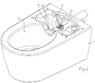
- the reference numeral 1 designates a toilet body made of ceramic, which has an opening of a toilet bowl 2 visible from the front and an opening 3 visible behind it for the installation of shower equipment components.
- the lowering numbered 4 is used for the passage of a shower arm, not shown here, of the shower device, also not shown.
- the flushing water connection 5 to which the pipe section 6 is connected can be seen to the right behind it.
- 7 denotes a pipe section for the sewage connection 14 below.
- the pipe sections 6, 6 ', 7, 7' are made of plastic.
- Figure 2 the same situation can be seen, however, a line pipe section 6 'is drawn, which runs straight, whereas the line pipe section 6 from Figure 1 creates a small jump in height.
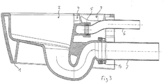
- Figure 3 shows in longitudinal section the height jump caused by the pipe section 6 and, moreover, the shape of the bowl.
- the jump in height is advantageous here in order to compensate for the relatively low position of the flushing water connection as a result of the lowering 4 for the shower arm. Accordingly the pipe section 7 runs straight. According to Figure 2 (and 4th ) the toilet must be installed higher accordingly.
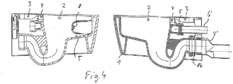
- Figure 4 shows two longitudinal sections placed side by side at the same level, with the viewing direction on the right Figure 3 matches, but the pipe sections 6 'and 7' from Figure 2 are used. On the left the pipe sections are left out and you can see the connecting pieces freely. In particular, the flushing water inlet opening 8, which communicates with the flushing water connection 5, can be seen here.
- Figure 5 shows a section through the toilet body 1 from Figures 1 to 4 , but in the width direction (vertical section plane) and looking towards the rear.
- a pipe bend 9 on the right which establishes this connection. It is made in one piece with the ceramic toilet body, using the hollow casting process. It runs hidden from view within an outer cladding wall 10 and an inner bowl wall 11.
- the flushing water passes from a concealed cistern, not shown, through a flushing elbow, also not shown, directly (without an intermediate piece) into the pipe section 6 or 6 'and via this and the flushing water connection 5 into the pipe bend 9, to through the flushing water inlet opening 8 into the bowl 2 to arrive.
- the rinsing water makes a circular and spiral downward movement, which is supported by the shape of the bowl, which is the subject of another patent application. In any case, the flushing water flow completely wets the illustrated inner walls of the toilet bowl 2 and is then discharged via the illustrated siphon bend, the waste water connection 14 and the pipe section 7 or 7 'connected to it.
- a height adjustment can be made by choosing between different pipe sections 6, 6 '.
- the mechanical fastening can be adjusted using elongated holes.
- the height adjustment on the part of the In this case, the waste water line is solved in a similar way as for the flushing water line, namely by means of different pipe sections 7, 7 '.
- the height adjustability of the waste water connection in the wall which is usually available.
- the rear of the toilet body 1 (in the Figures 1 and 2 right back, in the Figures 3 and 4th (right) on the right) is mechanically decoupled from the flushing water supply line and also the waste water line.
- the flushing water supply line is designed in an essential area, namely from the flushing water connection 5 through the pipe bend 9 to the flushing water inlet opening 8, in a streamlined, seamless and technically favorable manner, namely integrated with the rest of the toilet body 1 in the hollow casting process.
- the transition required at the flushing water connection 5 is unavoidable (at any point), but in this exemplary embodiment takes place directly on the pipe section 6, which in turn is led directly to the flushing bend, so that a minimal number of transitions and parts are used.
- the connection between the pipe sections 6, 6 'or 7, 7' and the toilet ceramic body 1, that is to say the connections 5 and 14, is implemented with conventional elastomer seals. These connections are reliable and permanently tight and easily accessible at the point shown in comparison z. B. to a likewise conceivable transition in the immediate vicinity of the flushing water inlet opening 8, see. also the EP 3 064 663 A1 .
- the distance between the flushing water connection 5 and the connection plane, that is to say the plane of the wall, is 12.5 cm in this exemplary embodiment.
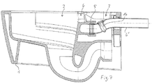
- Figure 6 shows a view like Figure 1 , but in a region of the pipe section 6 close to the flushing water connection 5, a cover 12 of a connection opening 13 provided on the upper side of the lateral surface of the pipe section 6 can be seen, which in turn is shown in FIG Figure 8 is drawn without a cover.
- Figure 7 shows one by the way Figure 3 corresponding section, with a flushing water throttle 14 is shown, which is designed to be integrated with the cover 12 and is used to adapt the flushing water flow to the individual pressure conditions.
- connection opening 13 for. B. also an odor extraction device can be connected, which is not shown (but in the EP 3 064 663 A1 is shown in a similar form), including the connection opening also z. B. can be provided laterally instead of above. Furthermore, in the connection opening 13 z. B. a cage for a cleaning or disinfection tablet or similar additives can be installed.
- the toilet shown z. B. according to Figure 3 can also be coupled with an ordinary straight pipe section 6 '.
- a toilet can also include the seat ring (not shown) and the cover (or the shower device) not shown, which are not essential for the invention, are missing in the exemplary embodiment and are therefore not an essential part of the subject matter of the invention.
Landscapes
- Health & Medical Sciences (AREA)
- Life Sciences & Earth Sciences (AREA)
- Engineering & Computer Science (AREA)
- Hydrology & Water Resources (AREA)
- Public Health (AREA)
- Water Supply & Treatment (AREA)
- Sanitary Device For Flush Toilet (AREA)
- Producing Shaped Articles From Materials (AREA)
Description
- Die vorliegende Erfindung betrifft ein Klosett mit Wasserspülung, kurz WC, das dementsprechend einen Spülwasseranschluss aufweist, sowie dessen Verwendung.
- WCs sind seit langer Zeit üblicher Standard und weit verbreitet. Ihrer Funktion entsprechend weisen sie einen Anschluss für Spülwasser auf, das von einer Spülwasserversorgung stammt, etwa einem Spülkasten oder auch einer Spülwasserleitung ohne Spülkasten, aber mit Spülventil. Von dem Spülkasten führt regelmäßig ein vertikales Rohrstück nach unten zu einem sogenannten Spülbogen, in dem die Leitungsrichtung um etwa 90 Grad auf das WC zu geändert wird. Wenn es keinen Spülkasten gibt, kann eine entsprechende Spülwasserleitung beispielsweise horizontal in einer Wand hinter dem WC verlaufen und ist ebenfalls über einen Spülbogen (also ein Eckstück) erreichbar.
- Ein WC besteht im Wesentlichen aus einem WC-Körper, häufig aus Keramik. Der WC-Körper hat regelmäßig eine Hinterseite, mit der er an eine Installationswand herangerückt wird. Bei hängender Montage hängt der WC-Körper mit dieser Hinterseite an der Wand; er kann aber auch einen eigenen Standfuß aufweisen. Die Anschlüsse erfolgen regelmäßig über die Hinterseite, wozu der WC-Körper an der Hinterseite entsprechende Anschlussstutzen für das Spülwasser und natürlich auch für das Abwasser aufweist. Der Installateur verbindet diese regelmäßig in dem Keramikkörper integrierten Anschlussstutzen über nach Bedarf zugeschnittene Leitungsrohrstücke mit z.B. dem Spülbogen und einem wandseitigen Abwasseranschluss, also Zugang zur Kanalisation.
- Das durch den Spülwasseranschluss gelieferte Spülwasser wird konventionellerweise entlang einem Spülrand in die WC-Schüssel verteilt. Der Spülrand ist dabei entlang einem oberen Rand der WC-Schüssel nach innen überhängend ausgebildet und verteilt das Spülwasser ähnlich einem Duschkopf über eine Vielzahl nach unten gerichtete Öffnungen.
- In jüngerer Vergangenheit sind zunehmend WCs auf den Markt gekommen mit einer einzelnen (oder wenigen) in einer Seitenwand der WC-Schüssel angeordneten Spülwassereintrittsöffnung (oder wenigen solcher Öffnungen), die das Spülwasser im Wesentlichen horizontal und entlang der WC-Schüssel-Innenwand einführt. Solche Spülwassereintrittsöffnungen sind oft nicht hinten, sondern seitlich vorgesehen.
- Bei solchen WCs wird das Spülwasser üblicherweise entlang einem gekrümmten Leitungsbogen zu der Spülwassereintrittsöffnung geführt, der integriert mit dem WC-Körper ausgebildet sein kann und analog wie bei oben beschriebenen konventionellen WCs bis zu einem Anschlussstutzen an der WC-Hinterseite, also an der Wandebene, führt.
- Mit "hinten" ist dabei die nach hinten gerichtete Orientierung aus der Perspektive eines auf dem WC sitzenden Benutzers gemeint, also hinter dessen Rücken und auf die Wand zu gerichtet. Analog entspricht "vorne" der Blickrichtung dieses Benutzers geradeaus. So verstehen sich auch die Angaben "seitlich" und "Breitenrichtung", nämlich aus der Perspektive dieses Benutzers rechts oder links bzw. in Richtung seiner Schultern. Dies gilt für den Rest dieser Beschreibung und die Ansprüche.
- Zum Stand der Technik wird auf die
EP 2 993 247 A1 , dieGB 2 431 937 A EP 3 054 061 A1 verwiesen, die alle gattungsgemäße WCs mit mittigem hinterseitigem integriertem Spülwasseranschluss zeigen, der ausweislich der Figuren in einem kleinen Abstand von der Hinterseite des WC-Körpers selbst liegt. Die Anschlüsse münden jeweils in Kammern in dem WC-Körper, von denen dann weiterführende Spülwasserleitungen in den WC-Körper quer abzweigen. DieEP 3 064 663 A1 hingegen zeigt einen neben einer WC-Schüssel angeordneten integrierten Spülwasseranschluss, zu dem eine längere und gebogene Kunststoffrohrleitung führt, in die eine Strömungsdrossel und eine Nebenkammer für eine Geruchsabsaugung integriert sind und die eine Querschnittsformanpassung von einem runden zu einem länglichen Hochkantquerschnitt bewerkstelligt. - Der Erfindung liegt das Problem zugrunde, ein hinsichtlich des Spülwasseranschlusses verbessertes WC anzugeben.
- Das Problem wird gelöst durch ein WC mit einem WC-Körper, einer WC-Schüssel in dem WC-Körper, einer Spülwassereintrittsöffnung in der WC-Schüssel des WC-Körpers, einer in dem WC-Körper integrierten Leitung zwischen der Spülwassereintrittsöffnung und einem integrierten Spülwasseranschluss des WC, einem von dem WC-Körper separaten Leitungsrohrstück zum Anschluss an den Spülwasseranschluss des WC und Verbindung desselben mit einer Spülwasserversorgung für das WC, wobei der Spülwasseranschluss hinter der WC-Schüssel angeordnet ist, wobei der Spülwasseranschluss in einem Abstand von mindestens 10 cm vor der Hinterseite des WC-Körpers vorgesehen ist, und das Leitungsrohrstück zugunsten einer Höhenanpassbarkeit flexibel oder zugunsten der Höhenanpassbarkeit mit unterschiedlichem Höhenversatz mehrfach vorgesehen ist, sowie durch dessen vorteilhafte Verwendung.
- Bevorzugte Ausgestaltungen sind in den abhängigen Ansprüchen angegeben und werden im Folgenden zusammen mit der Grundidee der Erfindung näher erläutert. Dabei wird nicht mehr zwischen den einzelnen Anspruchskategorien unterschieden.
- Bei der vorliegenden Erfindung ist zwischen einem integrierten Spülwasseranschluss des WC und der Hinterseite des WC-Körpers ein Zwischenabstand vorgesehen. Dieser beträgt mindestens 10 cm.
- Unter dem Spülwasseranschluss wird dabei der Anschluss an dem WC-Körper selbst verstanden, also an einem Leitungsstück, das einerseits in dem WC-Körper integriert ist und andererseits von dem Spülwasseranschluss zu der Spülwasser-Eintrittsöffnung (in die WC-Schüssel) führt.
- Der Abstand wird beim Anschließen über ein entsprechendes Leitungsrohrstück überbrückt, worauf noch näher eingegangen wird. Dieses ist dann nicht mit dem WC-Körper integriert und kann auch aus einem anderen Material bestehen. Hinsichtlich des WC-Körpers selbst ist der Spülwasseranschluss vorzugsweise ohne Verbindung zu der Hinterseite des WC-Körpers. Das gilt insbesondere für WCs mit Zusatzfunktionen, vor allem Dusch-WCs, die hier ein bevorzugter Anwendungsfall sind. Dort ist zwischen der Hinterseite der WC-Schüssel selbst und der Hinterseite des WC-Körpers und/oder über diesem Bereich ein gewisses Volumen an technischen Einrichtungen für die Duschfunktion und andere Funktionen unterzubringen, sodass der Abstand zwischen der Schüsselhinterseite und der WC-Körperhinterseite regelmäßig größer ausfällt als bei einfachen WCs ohne Zusatzfunktion.
- Bevorzugt ist eine Ausgestaltung des WC-Körpers aus Keramik. Das Leitungsrohrstück kann aber z. B. aus Kunststoff bestehen. Bei der keramischen Ausgestaltung des WC-Körpers kann die beschriebene Leitung zwischen Spülwasser-Eintrittsöffnung und Spülwasseranschluss in dem sogenannten Hohlgussverfahren integriert ausgeführt werden.
- "Integriert" heißt also, im gleichen Material und in einem einheitlichen Herstellungsverfahren hergestellt. Dabei gibt es in der Regel keine sichtbaren Grenzen oder Materialübergänge.
- Bei der Herstellung eines WC-Körpers aus Keramik mit in konventioneller Weise bis zur Hinterseite des WC-Körpers geführter Keramikleitung für das Spülwasser ist der entsprechende Anschlussstutzen in der Regel mit anderen keramischen Teilen an der Hinterseite verbunden, insbesondere mit einem Rahmen des WC-Körpers. Die Erfinder haben hierbei eine etwas erhöhte Häufigkeit von Rissen festgestellt, die bei der Keramikherstellung (einschließlich Brennen und Trocknung), aber auch bei der mechanischen Belastung durch das Gewicht des Benutzers danach verursacht sein können. Es hat sich jedenfalls als problematisch erwiesen, mit dem Leitungsstück für das Spülwasser gewissermaßen einen "Hebel" zur Krafteinleitung an die Hinterseite des WC-Körpers zu bringen.
- Wenn man andererseits die Leitung ohne solche mechanische Verbindung bis zur Hinterseite führt, ergibt sich ein relativ langes und insoweit "ungestütztes" Leitungsstück, das seinerseits bruch- oder rissempfindlich sein kann.
- Außerdem macht dieses Stück die Herstellung des WC-Körpers unnötig aufwendiger, ob diese nun in Kunststoff oder in Keramik erfolgt.
- Ferner hat sich erwiesen, dass durch das infolge des Abstands nötige Leitungsrohrstück (vorzugsweise aus Kunststoff) in sehr einfacher Weise und mit verschiedenen weiter unten zu erläuternden Vorteilen eine Überbrückung stattfinden kann.
- Die Erfindung eignet sich besonders auch für die eingangs bereits erwähnten WCs ohne klassischen Spülrand, aber mit seitlicher Spülwasser-Eintrittsöffnung in der WC-Schüssel. Hier wird der diese Spülwasser-Eintrittsöffnung mit dem Spülwasseranschluss verbindende Leitungsbogen integriert mit dem WC-Körper ausgeführt, insbesondere in Keramik und insbesondere mit dem bereits erwähnten Hohlgussverfahren. Über die Länge dieses Leitungsbogens ergeben sich dann keine weiteren Übergänge zwischen separaten Stücken mit Durchmessersprüngen, Klebestellen, Dichtungen oder ähnlichen Elementen, die die Strömung behindern, Ansätze für Verschmutzungsprobleme bieten, den Herstellungsaufwand erhöhen, Undichtigkeitsrisiken bergen und/oder die Montage verkomplizieren.
- Der Spülwasseranschluss ist dabei (und ganz allgemein bei dieser Erfindung), vorzugsweise mittig bezüglich der Breitenrichtung, also hinter der WC-Schüssel zentrisch. Bei dem gerade beschriebenen Fall mit dem Leitungsbogen führt dieser also nicht nur hinter die WC-Schüssel, sondern auch in einen Bereich hinter deren Mitte, vgl. das Ausführungsbeispiel.
- Mit der Erfindung kann auch bei solchen Leitungsbogen, die regelmäßig einen nicht-runden (z.B. ovalen) Querschnitt aufweisen, der Spülwasseranschluss selbst wieder einen kreisrunden Querschnitt haben. Damit können übliche Anschlusstechniken, also insbesondere eine kreisrunde Muffe seitens des Spülwasseranschlusses des WC und ein eingestecktes Rohrende mit einer üblichen Dichtung, Verwendung finden. Bei nicht-runden Querschnitten wurde stattdessen z. B. geklebt, was vergleichsweise aufwendiger und weniger zuverlässig ist.
- Ein weiterer mit der Erfindung erzielbarer Vorteil liegt in einer Verminderung der benötigten Leitungsanschlüsse bzw. Einzelteile an Leitungsstücken, indem nämlich das an den Spülwasseranschluss des WC anzuschließende (oder angeschlossene) Leitungsrohrstück relativ lang ausgelegt ist. Es kann dann bei der Installation nach hinten über den WC-Körper hinaus reichen und innerhalb der Wand, also hinter der Wandvorderseite, an die Spülwasserversorgung angeschlossen werden. Z. B. kann es direkt an den Spülbogen angeschlossen werden. Konventionellerweise hat man, wenn der mit dem WC-Körper integriert ausgeführte Leitungsteil nicht ohnehin bis zur WC-Hinterseite gereicht hat, insbesondere wenn ein gekrümmter Leitungsbogen entlang der WC-Schüssel nicht integriert ausgeführt wurde, diesen Leitungsbogen z. B. in Kunststoff realisiert. Vom Spülbogen aus wiederum wurde ein gerades Leitungsstück nach vorn geführt und passend abgelängt. Durch ein Durchziehen des an den (integrierten) Spülwasseranschluss des WC anzuschließenden Leitungsstücks bis in die Wand hinein kann demgegenüber die Zahl der Leitungsstücke und die Zahl der Übergänge verringert werden.
- Ein Aspekt der Erfindung besteht in einer Höhenanpassbarkeit der Spülwasserverbindung, indem das Leitungsrohrstück zugunsten einer Höhenanpassbarkeit flexibel oder zugunsten der Höhenanpassbarkeit mit unterschiedlichem Höhenversatz mehrfach vorgesehen ist. So kann die Höhenanpassbarkeit durch die Auswahl zwischen einer Mehrzahl unterschiedlich geformter Leitungsrohrstücke erfolgen. Damit kann eine Höhendifferenz je nach individuellem Einzelfall ausgeglichen werden. Wenn das WC an sich mit einer aus einem bestimmten Verstellbereich auszuwählenden Höhe montiert werden soll, können die mechanischen Befestigungen z. B. mit Langlöchern ausgeführt werden. Der Abwasseranschluss ist wandseitig in vielen Fällen bereits höhenverstellbar oder kann analog zum Spülwasseranschluss höhenverstellbar gelöst werden.
- Ferner kann das Leitungsrohrstück eine Anschlussöffnung in seiner Mantelfläche aufweisen, die in unterschiedlicher Weise genutzt werden kann. Dazu kann die Anschlussöffnung z. B. generell vorgesehen und mit einem z. B. schraubbaren Deckel versehen sein. Die Anschlussöffnung kann dann genutzt werden z. B. durch den Einbau einer Spülwasserdrossel. Eine solche Spülwasserdrossel kann die Spülwasserströmung an individuelle Situationen anpassen, wenn aufgrund einer bestimmten vorgegebenen Gefällehöhe zum Spülkasten oder eines vorgebenen Leitungsdrucks das Spülwasser möglicherweise mit zuviel kinetischer Energie einströmt. Insbesondere bei WCs mit der bereits mehrfach erwähnten seitlichen Spülwasser-Eintrittsöffnung in der Schüssel kann das von Vorteil sein, insbesondere um ein Herausspritzen zu verhindern. Zur Erläuterung wird verwiesen auf die
EP 3 064 663 A1 . - Alternativ (oder zusätzlich, etwa mit einer weiteren Anschlussöffnung) kann eine Geruchsabsaugeinrichtung angeschlossen werden, um störende Gerüche über die Spülwasserleitung aus der WC-Schüssel abzusaugen. Schließlich können Zusatzstoffe eingebracht werden, z. B. kann durch die Anschlussöffnung eine Einrichtung zum Einbringen von Reinigungs- oder Desinfektionsmitteln (etwa in Tablettenform) eingesetzt werden, z. B. ein Käfig.
- Ein weiterer Vorteil der Erfindung kann sich dann ergeben, wenn das Leitungsrohrstück im hinteren Bereich des WCs infolge seiner Kunststoffausführung dünnwandiger als ein entsprechendes Keramikrohrstück ausfällt und damit wertvoller Platz gespart wird. Dieser Platz kann z. B. für den Einbau von Duscheinrichtungskomponenten genutzt werden. In diesem Zusammenhang kann es auch von Vorteil sein, zunächst das Leitungsrohrstück bei der Montage wegzulassen und nur die Duscheinrichtungskomponenten vollständig zu verbauen, um dann erst das Leitungsrohrstück einzusetzen. Damit kann im Einzelfall wertvoller "Rangierraum" für den Einbau anderer Teile geschaffen werden.
- Im Folgenden wird die Erfindung anhand eines Ausführungsbeispiels näher erläutert.
- Figur 1
- zeigt eine perspektivische Darstellung von schräg oben vorn / rechts auf ein erfindungsgemäßes WC mit einem Leitungsrohrstück;
- Figur 2
- zeigt eine analoge Ansicht, jedoch mit einem anderen Leitungsrohrstück;
- Figur 3
- zeigt einen Längsschnitt durch das WC mit dem Leitungsrohrstück aus
Figur 1 ; - Figur 4
- zeigt einen Längsschnitt mit dem Leitungsrohrstück aus
Figur 2 , wobei in diesem Fall links daneben ein weiterer Längsschnitt mit umgekehrter Blickrichtung hinzugefügt ist, der eine Spülwassereintrittsöffnung zeigt; - Figur 5
- zeigt einen Querschnitt mit Blickrichtung nach hinten, und zwar etwas hinter der Spülwassereintrittsöffnung aus
Figur 4 , und zeigt damit einen integrierten Leitungsbogen des WC-Körpers; - Figur 6
- zeigt eine zu den
Figuren 1 und2 analoge perspektivische Darstellung mit dem Leitungsrohrstück ausFigur 1 , jedoch mit einer zusätzlichen Anschlussöffnung darin; - Figur 7
- zeigt einen Längsschnitt mit dem Leitungsrohrstück aus
Figur 5 , dessen Anschlussöffnung und eine darin eingebaute Drossel und - Figur 8
- entspricht
Figur 6 , jedoch mit abgenommenem Deckel der Anschlussöffnung. - In
Figur 1 ist mit dem Bezugszeichen 1 ein WC-Körper aus Keramik bezeichnet, der eine vorn sichtbare Öffnung einer WC-Schüssel 2 und eine dahinter sichtbare Öffnung 3 zum Einbau von Duscheinrichtungskomponenten aufweist. Die mit 4 bezifferte Absenkung dient zum Durchtritt eines hier nicht gezeigten Duscharms der ebenfalls nicht gezeigten Duscheinrichtung. Rechts dahinter ist der Spülwasseranschluss 5 zu sehen, an dem das Leitungsrohrstück 6 angeschlossen ist. 7 bezeichnet ein Leitungsrohrstück für den Abwasseranschluss 14 darunter. Die Leitungsrohrstücke 6, 6', 7, 7' sind aus Kunststoff gefertigt. - In
Figur 2 ist die gleiche Situation zu sehen, wobei jedoch ein Leitungsrohrstück 6' eingezeichnet ist, das gerade verläuft, wohingegen das Leitungsrohrstück 6 ausFigur 1 einen kleinen Höhensprung herstellt.Figur 3 zeigt im Längsschnitt den durch das Leitungsrohrstück 6 bewirkten Höhensprung und im Übrigen die Schüsselinnenform. - Der Höhensprung ist hier von Vorteil, um die relativ tiefe Lage des Spülwasseranschlusses infolge der Absenkung 4 für den Duscharm zu kompensieren. Dementsprechend läuft das Leitungsrohrstück 7 gerade. Gemäß
Figur 2 (und4 ) ist das WC entsprechend höher zu montieren. -
Figur 4 zeigt zwei auf gleicher Höhe nebeneinandergesetzte Längsschnitte, wobei rechts die Blickrichtung mitFigur 3 übereinstimmt, jedoch die Leitungsrohrstücke 6' und 7' ausFigur 2 eingesetzt sind. Links sind die Leitungsrohrstücke weggelassen und man sieht die Anschlussstutzen frei. Insbesondere erkennt man hier die Spülwassereintrittsöffnung 8, die mit dem Spülwasseranschluss 5 kommuniziert. -
Figur 5 zeigt einen Schnitt durch den WC-Körper 1 aus denFiguren 1 bis 4 , jedoch in Breitenrichtung (vertikale Schnittebene) und mit Blickrichtung nach hinten. Insbesondere erkennt man dabei einen Leitungsbogen 9 rechts, der diese Verbindung herstellt. Er ist einstückig mit dem Keramik-WC-Körper ausgebildet, und zwar im Hohlgussverfahren. Dabei läuft er innerhalb einer äußeren Verkleidungswand 10 und einer Schüsselinnenwand 11 sichtverdeckt. - Das Spülwasser tritt also bei einem Spülvorgang aus einem nicht gezeigten Unterputzspülkasten durch einen ebenfalls nicht gezeigten Spülbogen direkt (ohne Zwischenstück) in das Leitungsrohrstück 6 oder 6' und über dieses und den Spülwasseranschluss 5 in den Leitungsbogen 9, um durch die Spülwassereintrittsöffnung 8 in die Schüssel 2 zu gelangen. Darin vollzieht das Spülwasser eine kreisende und spiralförmig abwärtsgerichtete Bewegung, die durch die Schüsselinnenform unterstützt wird, was Gegenstand einer anderen Patentanmeldung ist. Jedenfalls benetzt die Spülwasserströmung die dargestellten Innenwände der WC-Schüssel 2 vollständig und wird dann über den dargestellten Siphonkrümmer, den Abwasseranschluss 14 und das daran angeschlossene Leitungsrohrstück 7 oder 7' abgeführt.
- Wie sich im Vergleich der
Figuren 1 und2 bzw. 3 und 4 (rechts) leicht ersehen lässt, kann durch Auswahl zwischen verschiedenen Rohrleitungsstücken 6, 6' eine Höhenanpassung vorgenommen werden. Die mechanische Befestigung kann wie gesagt durch Langlöcher angepasst werden. Die Höhenanpassung auf Seiten der Abwasserleitung ist in diesem Fall in ähnlicher Weise gelöst wie für die Spülwasserleitung, nämlich durch verschiedene Leitungsrohrstücke 7, 7'. Man könnte dort aber auch eine im Regelfall vorhandene Höheneinstellbarkeit des Abwasseranschlusses in der Wand ausnutzen. - Man kann ferner erkennen, dass die Hinterseite des WC-Körpers 1 (in den
Figuren 1 und2 rechts hinten, in denFiguren 3 und4 (rechts) auf der rechten Seite) mechanisch entkoppelt ist von der Spülwasserzuleitung und auch der Abwasserleitung. Gleichzeitig ist die Spülwasserzuleitung in einem wesentlichen Bereich, nämlich von dem Spülwasseranschluss 5 ausgehend durch den Leitungsbogen 9 bis zur Spülwassereintrittsöffnung 8, strömungsgünstig, nahtlos und produktionstechnisch günstig ausgeführt, nämlich im Hohlgussverfahren integriert mit dem übrigen WC-Körper 1. - Der an dem Spülwasseranschluss 5 notwendige Übergang ist (an irgendeiner Stelle) unvermeidlich, erfolgt aber bei diesem Ausführungsbeispiel direkt auf das Leitungsrohrstück 6, das seinerseits direkt zum Spülbogen geführt ist, sodass eine minimale Anzahl von Übergängen und Teilen Verwendung findet. Die Verbindung zwischen den Leitungsrohrstücken 6, 6' bzw. 7, 7' und dem WC-Keramikkörper 1, also den Anschlüssen 5 und 14, ist mit üblichen Elastomerdichtungen gesteckt ausgeführt. Diese Verbindungen sind zuverlässig und dauerhaft dicht und an der dargestellten Stelle gut zugänglich im Vergleich z. B. zu einem ebenfalls denkbaren Übergang in direkter Nähe der Spülwassereintrittsöffnung 8, vgl. auch die
EP 3 064 663 A1 . Der Abstand zwischen dem Spülwasseranschluss 5 und der Anschlussebene, also der Ebene der Wand, beträgt bei diesem Ausführungsbeispiel 12,5 cm. -
Figur 6 zeigt eine Ansicht wieFigur 1 , wobei jedoch in einem Bereich des Leitungsrohrstücks 6 nah an dem Spülwasseranschluss 5 ein Deckel 12 einer auf der Oberseite der Mantelfläche des Leitungsrohrstücks 6 vorgesehenen Anschlussöffnung 13 zu sehen ist, die ihrerseits inFigur 8 ohne Deckel gezeichnet ist.Figur 7 zeigt einen im ÜbrigenFigur 3 entsprechenden Schnitt, wobei eine Spülwasserdrossel 14 eingezeichnet ist, die mit dem Deckel 12 integriert ausgeführt ist und zur Anpassung der Spülwasserströmung an die individuellen Druckverhältnisse dient. Hierzu wird erneut verwiesen auf dieEP 3 064 663 A1 . - An die Anschlussöffnung 13 kann z. B. auch eine Geruchsabsaugeinrichtung angeschlossen werden, die nicht gezeigt ist (aber in der
EP 3 064 663 A1 in ähnlicher Form dargestellt ist), wozu die Anschlussöffnung auch z. B. seitlich statt oben vorgesehen sein kann. Ferner kann in die Anschlussöffnung 13 z. B. auch ein Käfig für eine Reinigungs- oder Desinfektionstablette oder ähnliche Zusätze eingebaut werden. - Schließlich kann man im Vergleich der
Figuren 1 und3 gut erkennen, dass die inFigur 1 gut sichtbare oberseitige Öffnung 3 des WC-Körpers 1 und das verfügbare Volumen darunter deutlich mehr Platz zum Einbauen verschiedener Bauteile bieten, wenn zumindest das Leitungsrohrstück 6 und möglicherweise auch das Leitungsrohrstück 7 zunächst weggelassen werden und erst nach erfolgter Montage dieser Bauteile eingesetzt werden. Auch insoweit eignet sich die Erfindung besonders für die Kombination mit einem WC mit Zusatzfunktion, insbesondere Duscheinrichtung. - Das dargestellte WC z. B. gemäß
Figur 3 kann auch mit einem ganz gewöhnlichen geraden Leitungsrohrstück 6' gekoppelt werden. Ferner kann man zu einem WC auch den nicht gezeigten Sitzring und nicht gezeigten Deckel (oder die Duscheinrichtung) zählen, die jedoch für die Erfindung nicht essenziell sind, beim Ausführungsbeispiel fehlen und damit nicht zwingender Bestandteil des Erfindungsgegenstandes sind.
Claims (14)
- WC mit
einem WC-Körper (1),
einer WC-Schüssel (2) in dem WC-Körper (1),
einer Spülwassereintrittsöffnung (8) in der WC-Schüssel (2) des WC-Körpers (1),
einer in dem WC-Körper (1) integrierten Leitung zwischen der Spülwassereintrittsöffnung (8) und einem integrierten Spülwasseranschluss (5) des WC,
einem von dem WC-Körper (1) separaten Leitungsrohrstück (6, 6', 6") zum Anschluss an den Spülwasseranschluss (5) des WC und Verbindung desselben mit einer Spülwasserversorgung für das WC,
wobei der Spülwasseranschluss (5) hinter der WC-Schüssel (2) angeordnet ist,
wobei der Spülwasseranschluss (5) in einem Abstand von mindestens 10 cm vor der Hinterseite des WC-Körpers (1) vorgesehen ist, dadurch gekennzeichnet, dass das Leitungsrohrstück (6, 6', 6") zugunsten einer Höhenanpassbarkeit flexibel oder zugunsten der Höhenanpassbarkeit mit unterschiedlichem Höhenversatz mehrfach vorgesehen ist. - WC nach Anspruch 1, bei dem die Spülwassereintrittsöffnung (8) in der WC-Schüssel (2) seitlich oder vorne angeordnet ist und über einen die integrierte Leitung bildenden Leitungsbogen (9) mit dem Spülwasseranschluss (5) verbunden ist, welcher Leitungsbogen (9) entlang einer Seite der WC-Schüssel (2) verläuft.
- WC nach Anspruch 1 oder 2, bei dem der Spülwasseranschluss (5) in Bezug auf eine Breitenrichtung des WC mittig angeordnet ist.
- WC nach einem der vorstehenden Ansprüche, bei dem der Spülwasseranschluss (5) einen kreisrunden Querschnitt aufweist.
- WC nach einem der vorstehenden Ansprüche, bei dem der WC-Körper (1) aus Keramik besteht, wobei die integrierte Leitung (9) zwischen der Spülwassereintrittsöffnung (8) und dem Spülwasseranschluss (5) vorzugsweise im Hohlgussverfahren hergestellt ist.
- WC nach einem der vorstehenden Ansprüche, ausgelegt zur hängenden Wandmontage an seiner Hinterseite.
- WC nach einem der vorstehenden Ansprüche, bei dem das Leitungsrohrstück (6, 6', 6") aus Kunststoff besteht.
- WC nach Anspruch 7, bei dem das Leitungsrohrstück (6, 6', 6") so dimensioniert ist, dass es in einem an den Spülwasseranschluss (5) angeschlossenen Zustand hinten über den WC-Körper (1) hinaus geht und in einer Wand und hinter einer Vorderseite der Wand, vor der das WC aufzustellen ist, an die Spülwasserversorgung angeschlossen werden kann, insbesondere an einen Spülbogen.
- WC nach einem der Ansprüche 7 oder 8, bei dem das Leitungsrohrstück (6") eine zusätzliche Anschlussöffnung (13) in seiner Mantelfläche aufweist.
- WC nach Anspruch 9 mit einer Spülwasserdrossel (14) zum Einbau in die Anschlussöffnung des Leitungsrohrstücks (6").
- WC nach Anspruch 9 oder 10 mit einer Geruchsabsaugeinrichtung zum Anschluss an die Anschlussöffnung (13) des Leitungsrohrstücks (6").
- WC nach einem der Ansprüche 9 bis 11, das dazu ausgelegt ist, durch die Anschlussöffnung (13) des Leitungsrohrstücks (6") dem Spülwasser Zusatzstoffe hinzuzufügen, insbesondere Reinigungs- oder Desinfektionstabletten.
- Verwendung eines WC nach einem der vorstehenden Ansprüche zum Anschluss an eine Spülwasserversorgung, wobei der Spülwasseranschluss (5) des WC über ein bzw. das in Anspruch 7 genannte Leitungsrohrstück (6, 6', 6") mit einer Spülwasserversorgung verbunden wird, welches Leitungsrohrstück (6, 6', 6") separat von dem WC-Körper (1) vorgesehen ist.
- Verwendung nach Anspruch 13 eines WC nach Anspruch 9, wobei an der Anschlussöffnung (13) des Leitungsrohrstücks (6") eine Spülwasserdrossel (14), eine Geruchsabsaugeinrichtung oder eine Einrichtung zum Einbringen von Zusatzstoffen in das Spülwasser montiert ist oder wird.
Priority Applications (5)
| Application Number | Priority Date | Filing Date | Title |
|---|---|---|---|
| DK17020366.5T DK3444408T3 (da) | 2017-08-18 | 2017-08-18 | Toilet med skyllevandsforbindelse |
| EP17020366.5A EP3444408B1 (de) | 2017-08-18 | 2017-08-18 | Wc mit spülwasseranschluss |
| PCT/EP2018/067079 WO2019034311A1 (de) | 2017-08-18 | 2018-06-26 | Wc mit spülwasseranschluss |
| AU2018319043A AU2018319043B2 (en) | 2017-08-18 | 2018-06-26 | Toilet with flushing water connection |
| CN201880052433.8A CN110998038A (zh) | 2017-08-18 | 2018-06-26 | 带有冲洗水连接件的马桶 |
Applications Claiming Priority (1)
| Application Number | Priority Date | Filing Date | Title |
|---|---|---|---|
| EP17020366.5A EP3444408B1 (de) | 2017-08-18 | 2017-08-18 | Wc mit spülwasseranschluss |
Publications (2)
| Publication Number | Publication Date |
|---|---|
| EP3444408A1 EP3444408A1 (de) | 2019-02-20 |
| EP3444408B1 true EP3444408B1 (de) | 2020-11-25 |
Family
ID=59686716
Family Applications (1)
| Application Number | Title | Priority Date | Filing Date |
|---|---|---|---|
| EP17020366.5A Active EP3444408B1 (de) | 2017-08-18 | 2017-08-18 | Wc mit spülwasseranschluss |
Country Status (5)
| Country | Link |
|---|---|
| EP (1) | EP3444408B1 (de) |
| CN (1) | CN110998038A (de) |
| AU (1) | AU2018319043B2 (de) |
| DK (1) | DK3444408T3 (de) |
| WO (1) | WO2019034311A1 (de) |
Cited By (2)
| Publication number | Priority date | Publication date | Assignee | Title |
|---|---|---|---|---|
| DE202021104161U1 (de) | 2021-08-04 | 2022-11-08 | Geberit International Ag | WC mit spezifischer Schüsselinnenform |
| EP4130407A1 (de) | 2021-08-04 | 2023-02-08 | Geberit International AG | Wc mit spezifischer schüsselinnenform |
Families Citing this family (1)
| Publication number | Priority date | Publication date | Assignee | Title |
|---|---|---|---|---|
| JP7423295B2 (ja) * | 2019-12-16 | 2024-01-29 | 株式会社Lixil | 水洗大便器及び便器装置 |
Citations (1)
| Publication number | Priority date | Publication date | Assignee | Title |
|---|---|---|---|---|
| EP2217766A1 (de) * | 2007-11-30 | 2010-08-18 | Villeroy & Boch Ag | Spülwassereinrichtung für ein toilettenbecken |
Family Cites Families (13)
| Publication number | Priority date | Publication date | Assignee | Title |
|---|---|---|---|---|
| JP2005105581A (ja) * | 2003-09-29 | 2005-04-21 | Toto Ltd | 圧送排水機能付き便器 |
| GB0522615D0 (en) * | 2005-11-05 | 2005-12-14 | Twyford Bathrooms | Improved water closet pans |
| EP2447426B1 (de) * | 2010-09-27 | 2013-03-06 | Geberit International AG | Dusch-WC |
| US9181689B2 (en) * | 2010-10-29 | 2015-11-10 | Lixil Corporation | Toilet apparatus |
| PL2568089T3 (pl) * | 2011-09-12 | 2020-05-18 | Geberit International Ag | Zastosowanie urządzenia mocującego WC i toalety myjącej |
| ES2562615T3 (es) * | 2012-05-25 | 2016-03-07 | Geberit International Ag | Retrete con dispositivo de absorción de olores |
| TR201815844T4 (tr) * | 2013-04-18 | 2018-11-21 | Tece Gmbh | Yıkama suyu dağıtıcısına entegre edilmiş, taharet musluğuna sahip wc. |
| JP6428993B2 (ja) * | 2013-12-12 | 2018-11-28 | Toto株式会社 | 水洗大便器 |
| PL2993274T3 (pl) * | 2014-09-05 | 2017-10-31 | Ceram Catalano S P A | Miska sedesowa o niskim poziomie hałasu |
| JP6414439B2 (ja) * | 2014-10-24 | 2018-10-31 | Toto株式会社 | 水洗大便器 |
| JP6573066B2 (ja) * | 2015-02-04 | 2019-09-11 | Toto株式会社 | 水洗大便器 |
| ES2812612T3 (es) * | 2015-03-03 | 2021-03-17 | Geberit Int Ag | Dispositivo sanitario |
| CN205990651U (zh) * | 2016-08-24 | 2017-03-01 | 唐山梦牌瓷业有限公司 | 横流虹吸式坐便器 |
-
2017
- 2017-08-18 EP EP17020366.5A patent/EP3444408B1/de active Active
- 2017-08-18 DK DK17020366.5T patent/DK3444408T3/da active
-
2018
- 2018-06-26 WO PCT/EP2018/067079 patent/WO2019034311A1/de active Application Filing
- 2018-06-26 AU AU2018319043A patent/AU2018319043B2/en active Active
- 2018-06-26 CN CN201880052433.8A patent/CN110998038A/zh active Pending
Patent Citations (1)
| Publication number | Priority date | Publication date | Assignee | Title |
|---|---|---|---|---|
| EP2217766A1 (de) * | 2007-11-30 | 2010-08-18 | Villeroy & Boch Ag | Spülwassereinrichtung für ein toilettenbecken |
Cited By (3)
| Publication number | Priority date | Publication date | Assignee | Title |
|---|---|---|---|---|
| DE202021104161U1 (de) | 2021-08-04 | 2022-11-08 | Geberit International Ag | WC mit spezifischer Schüsselinnenform |
| EP4130407A1 (de) | 2021-08-04 | 2023-02-08 | Geberit International AG | Wc mit spezifischer schüsselinnenform |
| WO2023011889A1 (de) | 2021-08-04 | 2023-02-09 | Geberit International Ag | Wc mit einer spezifischen schüsselinnenform |
Also Published As
| Publication number | Publication date |
|---|---|
| EP3444408A1 (de) | 2019-02-20 |
| AU2018319043A1 (en) | 2020-01-16 |
| CN110998038A (zh) | 2020-04-10 |
| AU2018319043B2 (en) | 2022-08-11 |
| WO2019034311A1 (de) | 2019-02-21 |
| DK3444408T3 (da) | 2020-12-21 |
Similar Documents
| Publication | Publication Date | Title |
|---|---|---|
| DE102012010580B4 (de) | Stand-WC mit angegossenem Spülkasten | |
| EP2604761B1 (de) | Wasserklosett | |
| EP2568089B1 (de) | Verwendung einer WC-Anschlussvorrichtung und eines Dusch-WCs | |
| EP3444408B1 (de) | Wc mit spülwasseranschluss | |
| EP2236683A1 (de) | Duschrinnenanordnung für Wandeinbau | |
| EP2986787A1 (de) | Wc mit intimdusche, die im spülwasserverteiler integriert ist | |
| EP3951110B1 (de) | Spültoilette | |
| EP2886729B1 (de) | Toilettenschüssel und Toilette | |
| EP2217766A1 (de) | Spülwassereinrichtung für ein toilettenbecken | |
| DE102009005319B4 (de) | Multifunktionale Toilettenanordnung | |
| DE102019105732A1 (de) | Sanitärgegenstand in Form eines WCs | |
| EP3670772B1 (de) | Wc-anschlussvorrichtung zum wandseitigen anschluss eines dusch-wc und verfahren zur installation eines dusch-wc unter verwendung einer wc- anschlussvorrichtung | |
| DE202017004300U1 (de) | WC mit Spülwasseranschluss | |
| DE202011109018U1 (de) | Wasserklosett | |
| EP2182124B1 (de) | Spülvorrichtung mit einer Ventilanordnung | |
| DE102004005759B4 (de) | Einrichtung zum Dosieren und Zuführen eines Mediums in einen Korpus einer Sanitäreinrichtung | |
| DE10314640A1 (de) | WC und zugehöriges Installationselement | |
| DE29815758U1 (de) | Kastenkörper für einen Spülkasten | |
| EP4317623A1 (de) | Vorrichtung zur druckspülung eines wc-beckens, wc-becken mit einer solchen vorrichtung und deren verwendung | |
| DE202023104666U1 (de) | Spülrandlose Spültoilette | |
| EP4105401A1 (de) | Spülrandloser sanitärgegenstand und verfahren zum spülen eines solchen | |
| DE102020100235A1 (de) | Sanitäreinrichtung umfassend ein Urinal und einen an das Urinal anzuschließenden oder angeschlossenen Absaugsiphon | |
| WO2022171276A1 (de) | Wc-becken | |
| DE2131375A1 (de) | Wasserspuelung eines Wasser-Klosetts | |
| DE2732313A1 (de) | Im hohlgussverfahren hergestelltes klosettbecken |
Legal Events
| Date | Code | Title | Description |
|---|---|---|---|
| PUAI | Public reference made under article 153(3) epc to a published international application that has entered the european phase |
Free format text: ORIGINAL CODE: 0009012 |
|
| STAA | Information on the status of an ep patent application or granted ep patent |
Free format text: STATUS: REQUEST FOR EXAMINATION WAS MADE |
|
| 17P | Request for examination filed |
Effective date: 20180416 |
|
| AK | Designated contracting states |
Kind code of ref document: A1 Designated state(s): AL AT BE BG CH CY CZ DE DK EE ES FI FR GB GR HR HU IE IS IT LI LT LU LV MC MK MT NL NO PL PT RO RS SE SI SK SM TR |
|
| AX | Request for extension of the european patent |
Extension state: BA ME |
|
| RBV | Designated contracting states (corrected) |
Designated state(s): AL AT BE BG CH CY CZ DE DK EE ES FI FR GB GR HR HU IE IS IT LI LT LU LV MC MK MT NL NO PL PT RO RS SE SI SK SM TR |
|
| STAA | Information on the status of an ep patent application or granted ep patent |
Free format text: STATUS: EXAMINATION IS IN PROGRESS |
|
| 17Q | First examination report despatched |
Effective date: 20191001 |
|
| GRAP | Despatch of communication of intention to grant a patent |
Free format text: ORIGINAL CODE: EPIDOSNIGR1 |
|
| STAA | Information on the status of an ep patent application or granted ep patent |
Free format text: STATUS: GRANT OF PATENT IS INTENDED |
|
| RIC1 | Information provided on ipc code assigned before grant |
Ipc: E03D 11/14 20060101ALN20200130BHEP Ipc: E03D 9/16 20060101ALN20200130BHEP Ipc: E03D 9/08 20060101ALN20200130BHEP Ipc: E03D 1/38 20060101ALI20200130BHEP Ipc: E03D 11/08 20060101AFI20200130BHEP |
|
| INTG | Intention to grant announced |
Effective date: 20200212 |
|
| GRAJ | Information related to disapproval of communication of intention to grant by the applicant or resumption of examination proceedings by the epo deleted |
Free format text: ORIGINAL CODE: EPIDOSDIGR1 |
|
| STAA | Information on the status of an ep patent application or granted ep patent |
Free format text: STATUS: EXAMINATION IS IN PROGRESS |
|
| INTC | Intention to grant announced (deleted) | ||
| RIC1 | Information provided on ipc code assigned before grant |
Ipc: E03D 9/16 20060101ALN20200520BHEP Ipc: E03D 11/08 20060101AFI20200520BHEP Ipc: E03D 1/38 20060101ALI20200520BHEP Ipc: E03D 9/08 20060101ALN20200520BHEP Ipc: E03D 11/14 20060101ALN20200520BHEP |
|
| GRAP | Despatch of communication of intention to grant a patent |
Free format text: ORIGINAL CODE: EPIDOSNIGR1 |
|
| STAA | Information on the status of an ep patent application or granted ep patent |
Free format text: STATUS: GRANT OF PATENT IS INTENDED |
|
| GRAJ | Information related to disapproval of communication of intention to grant by the applicant or resumption of examination proceedings by the epo deleted |
Free format text: ORIGINAL CODE: EPIDOSDIGR1 |
|
| STAA | Information on the status of an ep patent application or granted ep patent |
Free format text: STATUS: EXAMINATION IS IN PROGRESS |
|
| INTG | Intention to grant announced |
Effective date: 20200703 |
|
| INTC | Intention to grant announced (deleted) | ||
| GRAP | Despatch of communication of intention to grant a patent |
Free format text: ORIGINAL CODE: EPIDOSNIGR1 |
|
| STAA | Information on the status of an ep patent application or granted ep patent |
Free format text: STATUS: GRANT OF PATENT IS INTENDED |
|
| RIC1 | Information provided on ipc code assigned before grant |
Ipc: E03D 11/14 20060101ALN20200901BHEP Ipc: E03D 1/38 20060101ALI20200901BHEP Ipc: E03D 11/08 20060101AFI20200901BHEP Ipc: E03D 9/08 20060101ALN20200901BHEP Ipc: E03D 9/16 20060101ALN20200901BHEP |
|
| GRAS | Grant fee paid |
Free format text: ORIGINAL CODE: EPIDOSNIGR3 |
|
| GRAA | (expected) grant |
Free format text: ORIGINAL CODE: 0009210 |
|
| STAA | Information on the status of an ep patent application or granted ep patent |
Free format text: STATUS: THE PATENT HAS BEEN GRANTED |
|
| INTG | Intention to grant announced |
Effective date: 20201006 |
|
| AK | Designated contracting states |
Kind code of ref document: B1 Designated state(s): AL AT BE BG CH CY CZ DE DK EE ES FI FR GB GR HR HU IE IS IT LI LT LU LV MC MK MT NL NO PL PT RO RS SE SI SK SM TR |
|
| REG | Reference to a national code |
Ref country code: GB Ref legal event code: FG4D Free format text: NOT ENGLISH |
|
| REG | Reference to a national code |
Ref country code: CH Ref legal event code: EP |
|
| REG | Reference to a national code |
Ref country code: AT Ref legal event code: REF Ref document number: 1338460 Country of ref document: AT Kind code of ref document: T Effective date: 20201215 Ref country code: CH Ref legal event code: NV Representative=s name: TR-IP CONSULTING LLC, CH |
|
| REG | Reference to a national code |
Ref country code: DE Ref legal event code: R096 Ref document number: 502017008319 Country of ref document: DE |
|
| REG | Reference to a national code |
Ref country code: DK Ref legal event code: T3 Effective date: 20201218 |
|
| REG | Reference to a national code |
Ref country code: IE Ref legal event code: FG4D Free format text: LANGUAGE OF EP DOCUMENT: GERMAN |
|
| REG | Reference to a national code |
Ref country code: NL Ref legal event code: FP |
|
| PG25 | Lapsed in a contracting state [announced via postgrant information from national office to epo] |
Ref country code: GR Free format text: LAPSE BECAUSE OF FAILURE TO SUBMIT A TRANSLATION OF THE DESCRIPTION OR TO PAY THE FEE WITHIN THE PRESCRIBED TIME-LIMIT Effective date: 20210226 Ref country code: FI Free format text: LAPSE BECAUSE OF FAILURE TO SUBMIT A TRANSLATION OF THE DESCRIPTION OR TO PAY THE FEE WITHIN THE PRESCRIBED TIME-LIMIT Effective date: 20201125 Ref country code: NO Free format text: LAPSE BECAUSE OF FAILURE TO SUBMIT A TRANSLATION OF THE DESCRIPTION OR TO PAY THE FEE WITHIN THE PRESCRIBED TIME-LIMIT Effective date: 20210225 Ref country code: RS Free format text: LAPSE BECAUSE OF FAILURE TO SUBMIT A TRANSLATION OF THE DESCRIPTION OR TO PAY THE FEE WITHIN THE PRESCRIBED TIME-LIMIT Effective date: 20201125 Ref country code: PT Free format text: LAPSE BECAUSE OF FAILURE TO SUBMIT A TRANSLATION OF THE DESCRIPTION OR TO PAY THE FEE WITHIN THE PRESCRIBED TIME-LIMIT Effective date: 20210325 |
|
| PG25 | Lapsed in a contracting state [announced via postgrant information from national office to epo] |
Ref country code: BG Free format text: LAPSE BECAUSE OF FAILURE TO SUBMIT A TRANSLATION OF THE DESCRIPTION OR TO PAY THE FEE WITHIN THE PRESCRIBED TIME-LIMIT Effective date: 20210225 Ref country code: LV Free format text: LAPSE BECAUSE OF FAILURE TO SUBMIT A TRANSLATION OF THE DESCRIPTION OR TO PAY THE FEE WITHIN THE PRESCRIBED TIME-LIMIT Effective date: 20201125 Ref country code: PL Free format text: LAPSE BECAUSE OF FAILURE TO SUBMIT A TRANSLATION OF THE DESCRIPTION OR TO PAY THE FEE WITHIN THE PRESCRIBED TIME-LIMIT Effective date: 20201125 Ref country code: IS Free format text: LAPSE BECAUSE OF FAILURE TO SUBMIT A TRANSLATION OF THE DESCRIPTION OR TO PAY THE FEE WITHIN THE PRESCRIBED TIME-LIMIT Effective date: 20210325 Ref country code: SE Free format text: LAPSE BECAUSE OF FAILURE TO SUBMIT A TRANSLATION OF THE DESCRIPTION OR TO PAY THE FEE WITHIN THE PRESCRIBED TIME-LIMIT Effective date: 20201125 |
|
| REG | Reference to a national code |
Ref country code: LT Ref legal event code: MG9D |
|
| PG25 | Lapsed in a contracting state [announced via postgrant information from national office to epo] |
Ref country code: HR Free format text: LAPSE BECAUSE OF FAILURE TO SUBMIT A TRANSLATION OF THE DESCRIPTION OR TO PAY THE FEE WITHIN THE PRESCRIBED TIME-LIMIT Effective date: 20201125 |
|
| PG25 | Lapsed in a contracting state [announced via postgrant information from national office to epo] |
Ref country code: RO Free format text: LAPSE BECAUSE OF FAILURE TO SUBMIT A TRANSLATION OF THE DESCRIPTION OR TO PAY THE FEE WITHIN THE PRESCRIBED TIME-LIMIT Effective date: 20201125 Ref country code: SK Free format text: LAPSE BECAUSE OF FAILURE TO SUBMIT A TRANSLATION OF THE DESCRIPTION OR TO PAY THE FEE WITHIN THE PRESCRIBED TIME-LIMIT Effective date: 20201125 Ref country code: CZ Free format text: LAPSE BECAUSE OF FAILURE TO SUBMIT A TRANSLATION OF THE DESCRIPTION OR TO PAY THE FEE WITHIN THE PRESCRIBED TIME-LIMIT Effective date: 20201125 Ref country code: EE Free format text: LAPSE BECAUSE OF FAILURE TO SUBMIT A TRANSLATION OF THE DESCRIPTION OR TO PAY THE FEE WITHIN THE PRESCRIBED TIME-LIMIT Effective date: 20201125 Ref country code: LT Free format text: LAPSE BECAUSE OF FAILURE TO SUBMIT A TRANSLATION OF THE DESCRIPTION OR TO PAY THE FEE WITHIN THE PRESCRIBED TIME-LIMIT Effective date: 20201125 Ref country code: SM Free format text: LAPSE BECAUSE OF FAILURE TO SUBMIT A TRANSLATION OF THE DESCRIPTION OR TO PAY THE FEE WITHIN THE PRESCRIBED TIME-LIMIT Effective date: 20201125 |
|
| REG | Reference to a national code |
Ref country code: DE Ref legal event code: R097 Ref document number: 502017008319 Country of ref document: DE |
|
| PLBE | No opposition filed within time limit |
Free format text: ORIGINAL CODE: 0009261 |
|
| STAA | Information on the status of an ep patent application or granted ep patent |
Free format text: STATUS: NO OPPOSITION FILED WITHIN TIME LIMIT |
|
| PG25 | Lapsed in a contracting state [announced via postgrant information from national office to epo] |
Ref country code: AL Free format text: LAPSE BECAUSE OF FAILURE TO SUBMIT A TRANSLATION OF THE DESCRIPTION OR TO PAY THE FEE WITHIN THE PRESCRIBED TIME-LIMIT Effective date: 20201125 |
|
| 26N | No opposition filed |
Effective date: 20210826 |
|
| PG25 | Lapsed in a contracting state [announced via postgrant information from national office to epo] |
Ref country code: SI Free format text: LAPSE BECAUSE OF FAILURE TO SUBMIT A TRANSLATION OF THE DESCRIPTION OR TO PAY THE FEE WITHIN THE PRESCRIBED TIME-LIMIT Effective date: 20201125 |
|
| PG25 | Lapsed in a contracting state [announced via postgrant information from national office to epo] |
Ref country code: ES Free format text: LAPSE BECAUSE OF FAILURE TO SUBMIT A TRANSLATION OF THE DESCRIPTION OR TO PAY THE FEE WITHIN THE PRESCRIBED TIME-LIMIT Effective date: 20201125 |
|
| PG25 | Lapsed in a contracting state [announced via postgrant information from national office to epo] |
Ref country code: MC Free format text: LAPSE BECAUSE OF FAILURE TO SUBMIT A TRANSLATION OF THE DESCRIPTION OR TO PAY THE FEE WITHIN THE PRESCRIBED TIME-LIMIT Effective date: 20201125 |
|
| REG | Reference to a national code |
Ref country code: BE Ref legal event code: MM Effective date: 20210831 |
|
| PG25 | Lapsed in a contracting state [announced via postgrant information from national office to epo] |
Ref country code: IS Free format text: LAPSE BECAUSE OF FAILURE TO SUBMIT A TRANSLATION OF THE DESCRIPTION OR TO PAY THE FEE WITHIN THE PRESCRIBED TIME-LIMIT Effective date: 20210325 Ref country code: LU Free format text: LAPSE BECAUSE OF NON-PAYMENT OF DUE FEES Effective date: 20210818 |
|
| PG25 | Lapsed in a contracting state [announced via postgrant information from national office to epo] |
Ref country code: IE Free format text: LAPSE BECAUSE OF NON-PAYMENT OF DUE FEES Effective date: 20210818 Ref country code: BE Free format text: LAPSE BECAUSE OF NON-PAYMENT OF DUE FEES Effective date: 20210831 |
|
| P01 | Opt-out of the competence of the unified patent court (upc) registered |
Effective date: 20230507 |
|
| PG25 | Lapsed in a contracting state [announced via postgrant information from national office to epo] |
Ref country code: CY Free format text: LAPSE BECAUSE OF FAILURE TO SUBMIT A TRANSLATION OF THE DESCRIPTION OR TO PAY THE FEE WITHIN THE PRESCRIBED TIME-LIMIT Effective date: 20201125 |
|
| PG25 | Lapsed in a contracting state [announced via postgrant information from national office to epo] |
Ref country code: HU Free format text: LAPSE BECAUSE OF FAILURE TO SUBMIT A TRANSLATION OF THE DESCRIPTION OR TO PAY THE FEE WITHIN THE PRESCRIBED TIME-LIMIT; INVALID AB INITIO Effective date: 20170818 |
|
| PGFP | Annual fee paid to national office [announced via postgrant information from national office to epo] |
Ref country code: NL Payment date: 20230823 Year of fee payment: 7 |
|
| PGFP | Annual fee paid to national office [announced via postgrant information from national office to epo] |
Ref country code: IT Payment date: 20230831 Year of fee payment: 7 Ref country code: GB Payment date: 20230824 Year of fee payment: 7 Ref country code: CH Payment date: 20230902 Year of fee payment: 7 Ref country code: AT Payment date: 20230818 Year of fee payment: 7 |
|
| PGFP | Annual fee paid to national office [announced via postgrant information from national office to epo] |
Ref country code: FR Payment date: 20230821 Year of fee payment: 7 Ref country code: DK Payment date: 20230823 Year of fee payment: 7 Ref country code: DE Payment date: 20230822 Year of fee payment: 7 |
|
| PG25 | Lapsed in a contracting state [announced via postgrant information from national office to epo] |
Ref country code: MK Free format text: LAPSE BECAUSE OF FAILURE TO SUBMIT A TRANSLATION OF THE DESCRIPTION OR TO PAY THE FEE WITHIN THE PRESCRIBED TIME-LIMIT Effective date: 20201125 |
|
| REG | Reference to a national code |
Ref country code: NL Ref legal event code: PD Owner name: GEBERIT HOLDING AG; CH Free format text: DETAILS ASSIGNMENT: CHANGE OF OWNER(S), MERGE; FORMER OWNER NAME: GEBERIT INTERNATIONAL AG Effective date: 20240604 Ref country code: NL Ref legal event code: HC Owner name: GEBERIT INTERNATIONAL AG; CH Free format text: DETAILS ASSIGNMENT: CHANGE OF OWNER(S), CHANGE OF OWNER(S) NAME; FORMER OWNER NAME: GEBERIT HOLDING AG Effective date: 20240604 |