EP3441292B1 - Composants de bicyclette - Google Patents
Composants de bicyclette Download PDFInfo
- Publication number
- EP3441292B1 EP3441292B1 EP18187248.2A EP18187248A EP3441292B1 EP 3441292 B1 EP3441292 B1 EP 3441292B1 EP 18187248 A EP18187248 A EP 18187248A EP 3441292 B1 EP3441292 B1 EP 3441292B1
- Authority
- EP
- European Patent Office
- Prior art keywords
- support member
- support
- bicycle component
- support element
- bicycle
- Prior art date
- Legal status (The legal status is an assumption and is not a legal conclusion. Google has not performed a legal analysis and makes no representation as to the accuracy of the status listed.)
- Active
Links
Images
Classifications
-
- B—PERFORMING OPERATIONS; TRANSPORTING
- B62—LAND VEHICLES FOR TRAVELLING OTHERWISE THAN ON RAILS
- B62J—CYCLE SADDLES OR SEATS; AUXILIARY DEVICES OR ACCESSORIES SPECIALLY ADAPTED TO CYCLES AND NOT OTHERWISE PROVIDED FOR, e.g. ARTICLE CARRIERS OR CYCLE PROTECTORS
- B62J1/00—Saddles or other seats for cycles; Arrangement thereof; Component parts
- B62J1/08—Frames for saddles; Connections between saddle frames and seat pillars; Seat pillars
-
- B—PERFORMING OPERATIONS; TRANSPORTING
- B62—LAND VEHICLES FOR TRAVELLING OTHERWISE THAN ON RAILS
- B62J—CYCLE SADDLES OR SEATS; AUXILIARY DEVICES OR ACCESSORIES SPECIALLY ADAPTED TO CYCLES AND NOT OTHERWISE PROVIDED FOR, e.g. ARTICLE CARRIERS OR CYCLE PROTECTORS
- B62J1/00—Saddles or other seats for cycles; Arrangement thereof; Component parts
- B62J1/02—Saddles resiliently mounted on the frame; Equipment therefor, e.g. springs
- B62J1/06—Saddles capable of parallel motion up and down
-
- B—PERFORMING OPERATIONS; TRANSPORTING
- B62—LAND VEHICLES FOR TRAVELLING OTHERWISE THAN ON RAILS
- B62K—CYCLES; CYCLE FRAMES; CYCLE STEERING DEVICES; RIDER-OPERATED TERMINAL CONTROLS SPECIALLY ADAPTED FOR CYCLES; CYCLE AXLE SUSPENSIONS; CYCLE SIDECARS, FORECARS, OR THE LIKE
- B62K19/00—Cycle frames
- B62K19/30—Frame parts shaped to receive other cycle parts or accessories
- B62K19/36—Frame parts shaped to receive other cycle parts or accessories for attaching saddle pillars, e.g. adjustable during ride
-
- B—PERFORMING OPERATIONS; TRANSPORTING
- B62—LAND VEHICLES FOR TRAVELLING OTHERWISE THAN ON RAILS
- B62J—CYCLE SADDLES OR SEATS; AUXILIARY DEVICES OR ACCESSORIES SPECIALLY ADAPTED TO CYCLES AND NOT OTHERWISE PROVIDED FOR, e.g. ARTICLE CARRIERS OR CYCLE PROTECTORS
- B62J1/00—Saddles or other seats for cycles; Arrangement thereof; Component parts
- B62J1/08—Frames for saddles; Connections between saddle frames and seat pillars; Seat pillars
- B62J2001/085—Seat pillars having mechanisms to vary seat height, independently of the cycle frame
Definitions
- the present invention relates to a bicycle component for a bicycle that is at least partially powered by muscle power and has a seat support device that can be adjusted telescopically between at least two positions for adjusting a saddle height.
- the saddle when driving downhill, the saddle must be appropriately low so that the rider can put his weight behind the saddle in order to shift the center of gravity backwards.
- the saddle height When riding in the sitting position, the saddle height must be adjusted ergonomically to enable a favorable input of force into the drive.
- adjustable seat posts which are also known as telescopic supports.
- two telescoping tubes are used, with the thicker tube being inserted into the bottom of the frame and the thinner tube protruding upwards from the thicker tube.
- This can make a very A large adjustment range can be provided, as the inner tube can be immersed in the bicycle frame to almost any depth.
- the driver can usually operate the seat post adjustment mechanism from the handlebars. This means the saddle height can be adjusted while driving without the rider having to get off.
- a generic bicycle component with such a seat post is from the US 2014/061419 A1 known.
- Hydraulic seat supports allow adjustment to a wide variety of height positions.
- One disadvantage, however, is that they are difficult to dismantle, clean and maintain. Special tools are required for dismantling.
- hydraulic fluid can leak if disassembly is not carried out properly.
- the well-known adjustable seat posts generally work satisfactorily, but also offer potential for improvement.
- the known solutions can be optimized in terms of their practical suitability and their weight as well as their manufacturing costs and in particular the maintenance effort.
- an adjustable seat post is to be provided which is reliable and functions in an uncomplicated manner and is economical to produce and, in particular, is easy to maintain.
- the bicycle component according to the invention is intended for a bicycle that is at least partially powered by muscle power.
- the bicycle component comprises a seat support device that is telescopically adjustable between at least two positions for adjusting a saddle height.
- the bicycle component comprises at least one locking device for locking the seat support device in at least one of the positions.
- the seat support device comprises at least two support elements that are movable relative to one another, namely a first support element and at least one second support element.
- the first support element is on a frame structure of the bicycle; can be firmly attached.
- the second support element is used to hold a saddle.
- the first support element is arranged at least in sections within the second support element.
- the second support element can be moved at least in sections over the first support element.
- Such an “upside-down” design enables a very simple structure.
- the second support element is designed to be single-walled.
- the locking device is at least partially arranged within the first support element and comprises at least one locking element which, in the locked state, extends through at least one wall of the first support element into the second support element.
- the second support element slides on the first support element during a height adjustment (of a saddle) and/or is guided through the first support element.
- the bicycle component according to the invention offers many advantages.
- the arrangement of the two support elements according to the invention offers a significant advantage.
- This allows the second or upper support element can be designed structurally independently of the frame structure and in particular of the seat tube diameter. This results in significantly higher degrees of freedom for the design and significantly more flexible design options in order to obtain a reliable and cost-optimized seat support device.
- the bicycle component according to the invention can therefore also be used particularly well in other types of ferry bikes than mountain bikes, e.g. B. on racing bikes, cyclo-cross bikes and trekking bikes and e-bikes.
- the bicycle component according to the invention therefore also enables an advantageous weight reduction, which is particularly advantageous for sports bikes.
- Another advantage is that there are higher degrees of freedom for mounting the saddle on the second support element.
- the upper part of telescopic seat posts could only be designed within very narrow limits, as it had to have a particularly small diameter in order to fit into the lower part when the saddle was retracted.
- the lower part could't simply be enlarged because it has to fit into the seat tube of the frame.
- the first support element consists of a light material. It is possible for the first and/or the second support element to consist at least partially or completely of a fiber-reinforced material such as a carbon material. Particularly preferably, the first support element consists at least partially and in particular at least to a significant extent or essentially completely or completely (at least) one fiber composite material.
- the wall thickness of the first support element can be designed independently of the dimensions of the upper support element.
- the first or lower support element can be designed with an optimal lightweight construction.
- the lower part of telescopic seat posts had to be made so thin-walled that the upper part could be immersed in order to make telescoping possible.
- the lower support element can z. b. be made so large that it can be inserted precisely into the seat tube. This results in an overall considerably stiffer and more resilient and at the same time weight-optimized seat support device.
- the inventive arrangement of the two support elements means that the seat support device is considerably less sensitive to contamination and therefore offers a particularly reliable function. Because the upper support element can be moved over the lower support element, dirt can be wiped off much more easily and simply fall down. In particular, dirt and moisture do not collect directly at the top of the connection point between the two support elements, but are wiped off downwards.
- the term telescoping is understood to mean, in particular, a relative telescoping of the support elements.
- the second support element in particular can be pushed over the first support element at least in sections.
- the second support element moves upwards at least in sections on the first support element.
- the first support element telescopes into the second support element or the second support element moves on the first support element.
- the bicycle component can be designed as a seat post.
- Tubular support elements are preferably provided.
- the support elements are at least partially hollow.
- the second support element is arranged in particular at the top and the first support element is arranged in particular at the bottom.
- the first support element is in particular accommodated at least in sections in a seat tube of a frame structure of a bicycle.
- the frame structure can be part of the bicycle component.
- the bicycle component can also include a bicycle or be designed as such.
- At least one outer contour of the first support element and at least one inner contour of the second support element are designed to fit one another at least in sections, so that the second support element is guided along the first support element.
- the outer contour and the inner contour are designed to fit one another exactly where the two support elements slide or telescope along one another.
- the first support element is guided in the second support element or the second support element is on the outside of the first Support element guided.
- the first support element can be an integral part of the frame structure of the bicycle or the bicycle frame and can be firmly connected to it or made in one piece with it.
- At least one anti-rotation device is arranged between the two support elements. This prevents the saddle from twisting during operation and also when lowering or extending the seat support device.
- the anti-twist protection is provided in particular by the outer contour of the first support element and the inner contour of the second support element.
- the anti-rotation device can also include at least one linear guide with at least one guide rail.
- the guide rail is, for example, embedded in a recess in the first or second support element.
- the anti-rotation device can also have at least one toothing.
- a differently designed anti-twist device is also possible.
- the anti-twist device enables smooth adjustment.
- the anti-twist device is designed to be essentially free of play or (practically) free of play.
- the support elements are cylindrical.
- an outer diameter of the first support element is smaller than an inner diameter of the second support element.
- the support elements can also be designed to be out of round at least in sections.
- the locking device is preferably arranged at least partially within one of the support elements and in particular within the first support element. This offers a particularly compact seat support device and low-maintenance accommodation.
- the first Support element arranged at least one receiving space in which the locking device is at least partially arranged.
- the locking device is arranged in the first support element to such an extent that only the at least one locking element is not arranged inside the first support element or outside of the first support element.
- the locking device can also be arranged at least partially in the second support element.
- the locking device preferably comprises at least one locking element.
- the locking element In the locked state, the locking element extends in particular through at least one wall of the first support element into the second support element. This offers a structurally simple and at the same time very reliable locking and enables play-free implementation.
- the locking element In particular, in the locked state, the locking element extends into at least one wall of the second support element.
- the first support element can comprise at least one through opening. For example, at least one hole is arranged in the wall.
- a plurality of locking elements is provided.
- the locking device is particularly suitable and designed to positively block relative mobility of the support elements to one another by means of the locking element.
- the locking element In the locked state, the locking element extends in particular only into part of a wall of the second support element.
- the second support element comprises at least one recess in the wall in which the locking element is arranged in the locked state.
- the Recess is designed, for example, as a depression or depression. However, it is also possible for the locking element to pass through the wall of the second support element in the locked state.
- the locking device is particularly suitable and designed to at least partially press the locking element into at least one recess in the second support element by means of at least one piston element. This ensures reliable positioning of the locking elements.
- a locked position exists when the piston element presses the locking element into the second support element.
- the piston element presses the locking element into the recess of the second support element.
- the locking device comprises at least one piston element. The recess is arranged in particular in the wall of the second support element.
- the piston element is movable in particular in the direction of a longitudinal axis of the support elements.
- the piston element presses the locking element transversely to the longitudinal axis of the support element.
- the piston element comprises at least one wedge surface with which a longitudinal movement of the piston element can be converted into a transverse movement of the locking element.
- the piston element is rod-shaped and/or cylindrical.
- the wedge surface is preferably formed on a cone and is designed in a conical shape. It is also possible for the piston element to be annular and/or designed as a bushing.
- the wedge element is adapted to an inner diameter and/or an inner contour of the first support element.
- the piston element is guided in the first support element and is preferably linear guided.
- the locking element or the locking elements is or are preferably inserted loosely and are in particular not guided.
- the piston element is preferably movable into at least one release position in the direction of a longitudinal axis of the first support element.
- the piston element does not press the locking element into the second support element in the release position.
- the piston element has at least one recess in which the locking element can be received in the release position.
- the locking element is no longer arranged in (the wall of) the second support element in the release position.
- the bicycle component in particular comprises at least one actuating device for releasing and/or activating the locking mechanism.
- the actuating device is particularly suitable and designed to move the piston element into the release position and/or into the locked position.
- the actuating device can be at least partially manually or completely manually operable. Motor-assisted and/or fully automatic operation and/or wireless operation and functionality are also possible. In preferred embodiments, a mechanical solution is implemented, although it is reserved to implement electrical and/or remote-controlled and/or wireless control options if these are technically possible and legally permissible.
- the piston element for assuming the release position in the direction of an end of the first support element facing away from the second support element or one in the Frame structure removable end of the first support element movable.
- the piston element can be moved to assume the release position in the direction of an end of the first support element facing away from the second support element by pulling and preferably by at least one cable pull device.
- the wedge element can be moved in particular in the direction of that end of the first support element which is opposite the end of the first support element connected to the second support element.
- the wedge element can in particular be moved from the locked position into the release position by moving it to the end of the first support element, which can be received in the frame structure.
- the piston element is particularly preferably suitable and designed to be pulled into the release position by means of at least one actuating device. Such pulling can be implemented particularly inexpensively and robustly.
- the piston element is pulled with the actuating device to an end of the first support element, which can be received in the frame structure or which faces away from the second support element. It is also possible for the piston element to be pressed into the release position by means of the actuating device.
- the bicycle component comprises at least one actuation device for releasing and/or activating the locking device.
- the actuating device is in particular the actuating device described above, by means of which the piston element is pulled into the release position.
- the actuating device is preferably at least partially mechanical.
- the actuation device can be complete be mechanically designed.
- the actuating device comprises at least one cable pull device with at least one cable pull.
- the actuating device can comprise at least one mechanical operating lever with which the cable pull can be moved into at least one position or at least one of the two positions (released/locked).
- a cable pull device offers many advantages and is, for example, particularly low-maintenance and operationally reliable.
- the actuating device is suitable and designed to pull the piston element by means of the cable pull device.
- the cable runs in particular within the first support element.
- the cable also runs within the frame structure and in particular a seat tube of the bicycle.
- the cable pull is not positioned or held in a precisely defined manner in positions when the piston element is not locked.
- the actuating device can then be moved smoothly in at least one direction without the user receiving haptic feedback. It may then appear to the user that the seat support device is not operating in a defined manner and the user's confidence in its reliability may be compromised.
- the cable pull can be coupled with a cable tensioner in order to provide defined haptic feedback for the user at all times.
- the rope tensioner prevents play that might otherwise occur.
- the cable pull is preferably coupled in particular to the piston element via at least one cable tensioner.
- the rope tensioner preferably comprises at least one Pre-tensioning unit that leads to a tightening of the rope.
- the biasing unit can be designed as a mechanical spring, but can also be designed, for example, on a magnetic basis.
- the pretensioning unit is preferably arranged on a sliding element on which the or one end of the cable is held. The sliding element is pressed into a prestressed state via the prestressing unit.
- a pretensioning force of the pretensioning unit is opposite to a pretensioning of the pretensioning device.
- the level of the prestressing force of the prestressing unit is preferably significantly lower than a level of the prestressing force of the prestressing device, so that an effective force of the prestressing device always acts.
- the prestressing force of the prestressing unit is less than half as large and is in particular less than a quarter or eighth of the prestressing force of the prestressing device.
- the pretensioning unit ensures that a force for tensioning the cable is applied in every state of the actuating device or in every position of the (mechanical) operating lever.
- the user receives feedback of a precisely defined functionality at any time.
- the actuating device is at least partially designed to be hydraulic.
- the actuating device preferably comprises at least one control part for pulling or tensioning the cable.
- the control panel can be mounted in particular on a driver's handlebar device.
- the operating part is in particular also designed for actuating and/or tensioning and/or relaxing the cable pull.
- the operating part can be suitable and designed to fix the cable pull, for example in the release position and/or the locked position.
- the pulley can be in one of the two positions e.g. B. be preloaded by a spring.
- the cable exits from an axial end face of the first support element.
- This enables the cable to be laid in a well-protected and easy-to-assemble manner, for example within the frame structure of the bicycle.
- the cable exits at one end of the first support element, which can be accommodated in the frame structure or is facing away from the second support element.
- the cable exits at one end of the first support element, which in an operational position is directed downwards or towards the ground.
- the cable pull device is suitable and designed so that the cable pull can be laid within a frame structure of a bicycle and in particular at least within a seat tube. It is also possible for the cable pull to exit on a radial side of the first support element.
- the bicycle component in particular comprises at least one preloading device or a preloading device, which can be preloaded by pulling the piston element into the release position.
- the pretensioning device is particularly suitable and designed to move the piston element from the release position into the locked position when the cable pull is relaxed. This offers a cost-effective and reliable reset of the locking device. This can reliably ensure that the saddle remains in the desired position after adjustment.
- the pretensioning device includes in particular at least one energy accumulator and, for example, at least one spring and/or gas spring.
- the piston element is in the counter-tensioning force of the pretensioning device Release position movable.
- the actuating device is suitable and designed to automatically return the piston element to the locked position by means of the pretensioning device when there is no longer any tensile stress on the piston element or when the cable is no longer pulled.
- the biasing device is particularly suitable and designed to move the piston element from the release position into the locked position when the piston element is no longer actively held in the release position.
- the locking element comprises at least one ball or is designed as at least one. With such a ball, it can be achieved particularly inexpensively and without additional springs or the like that the locking is released when the piston element is pulled into the release position.
- a plurality of locking elements and in particular balls are particularly preferably provided. For example, two or three or four or more locking elements are provided.
- the locking element can also include at least one pin and/or at least one pawl or the like. Other suitable configurations of the locking element are also possible. It is possible for the locking element to be assigned at least one biasing device, which moves the locking element out of the second support element when the wedge element is in the release position.
- At least one energy storage device is preferably arranged within the second support element.
- the bicycle component comprises at least one energy storage device.
- the energy storage device is particularly suitable and designed by a Retracting the first support element into the second support element to be at least partially charged.
- the energy storage device is particularly suitable and designed to be at least partially unloaded by extending the first support element from the second support element, so that the seat support device can be extended at least partially automatically.
- Such a power storage device enables the seat support device to be reset very comfortably. For example, you only need to lift your buttocks and operate the control panel.
- the energy storage device can be charged in particular by the driver's weight.
- the energy storage device is supported in particular on the first and second support elements.
- the direction of force of the force storage device runs in particular in the direction of a longitudinal axis of the support elements. It is possible for a force for moving the saddle of the force storage device to be adjustable.
- the energy storage device in particular comprises at least one spring and/or at least one gas spring. In particular, the energy storage device also resets the cable pull and/or tensions it.
- the force storage device is designed such that an extension speed of the seat support device does not exceed a predetermined maximum speed.
- at least one spring and/or gas spring with a defined spring force is used for this purpose.
- Such a configuration has the advantage that excessive speed or even jerky extension of the second support element is reliably avoided. So can e.g. B. there is no need for a complex and weight-increasing damper device. However, the use of a damper device is possible. In In simple configurations, a friction element can be used with a longer stroke.
- At least one friction element is preferably arranged between the two support elements.
- the friction element preferably comprises at least one seal and in particular at least one sealing ring and/or at least one O-ring or the like.
- Such a friction element has the advantage that the speed can be slowed down when the seat support device is extended.
- Such final damping can act in particular as a function of the stroke and, for example, act on the last 10 mm or in particular 5 mm or 2 mm of the stroke.
- the first support element preferably comprises at least two tubular support sections that are firmly connected to one another in a connection area.
- the two support sections are preferably glued together.
- the two support sections can also be pressed and/or welded together.
- Other suitable non-positive and/or positive and/or material connection types are also possible.
- the use of light materials such as light metal is preferred. Fiber-reinforced plastics such as carbon materials are particularly preferred.
- connection area There is preferably at least one in the connection area
- Outer contour of the first support element is formed to fit precisely to at least one inner contour of the second support element. This has the advantage that smooth guidance is also achieved in the connection area.
- the outer contour and the inner contour are in particular designed such that the second support element is guided on the first support element.
- the support sections are arranged to overlap at least in the connection area.
- a coaxial arrangement of the two support sections is provided in the connection area. It is also possible to arrange the support sections in abutting manner.
- one support section has, at least in sections, a greater wall thickness than the other support section.
- the one support section has at least one through opening for the locking element.
- the other support section does not have a through opening for the locking element.
- the one support section consists at least to a significant extent of a fiber composite material.
- the other support section consists at least to a significant extent of a metallic lightweight construction material.
- the lightweight material is in particular an aluminum material and, for example, an aluminum alloy. Through such a mixture of materials, an optimal weight with a particularly high level of stability is achieved for each support section and its respective task. Lightweight construction materials containing magnesium or other metallic lightweight construction materials are also possible.
- both support sections can be made at least to a significant extent from a metallic lightweight material. This offers a particularly cost-optimized and at the same time very reliable seat post. Both support sections can also be made at least to a significant extent from a fiber composite material.
- the first support element can also be provided by a single or continuous tubular component.
- a single or continuous tubular component offers the advantages of the bicycle component according to the invention together with a special cost optimization.
- the component is made in particular from a fiber composite material or from a metallic lightweight material.
- first support element low metal, fiber composite material, carbon
- second support element By selecting suitable and light materials for the first support element (light metal, fiber composite material, carbon) and the second support element, a low overall weight with high stability can be achieved. If the locking elements and individual components wear out, they can easily be replaced.
- the locking elements preferably consist of a resilient material and in particular of a more resilient and wear-resistant material than the first and/or the second support element. This can save maintenance effort.
- the locking elements can be hardened and / or have at least one coating to protect the surface, for example. B. to harden.
- the piston element is guided in at least one support section, preferably in the support section with the greater wall thickness.
- the prestressing device is preferably accommodated in the support section with the greater wall thickness.
- the one support section provides a linear guide for the piston element. It is also preferred that the energy storage device is supported directly or indirectly on the one support section.
- a stroke of the seat support device is between 15 mm and 60 mm and in particular between 20 mm and 50 mm.
- the maximum stroke can also be 40mm or 30mm.
- a stroke between 30 mm and 50 mm is particularly preferably provided.
- a shorter or longer maximum stroke is also possible.
- a stroke of up to 80 mm or up to 100 mm is also conceivable and preferred.
- the stroke refers in particular to a movement of the second support element relative to the first support element.
- Such a design has proven to be particularly advantageous for adapting the seating position with regard to the aerodynamic properties of a bicycle, including the rider on it.
- a one millimeter reduction in seat height can reduce the power required to drive by up to 1W, or even more at high driving speeds, due to reduced wind resistance. Therefore, in many riding situations and especially in competitions or with e-bikes to improve the range, it is a great advantage to lower the saddle height. However, only a slight lowering should occur so that the ergonomically favorable sitting position is maintained.
- the bicycle component according to the invention is particularly suitable for this. The one before The maximum stroke described therefore enables a significant improvement in the aerodynamic properties and thus the driving performance of the driver or the e-bike drive.
- Security is increased.
- the user of an e-bike can lower the seat support device at a traffic light or when stopping in order to be able to support himself better and more safely with his foot.
- the seat support device can only be adjusted between two positions.
- the positions are in particular end positions. In particular, no intermediate positions are provided. This offers quick and comfortable adjustment of a seating position for reduced wind resistance.
- the invention provides a very simple and reliable option for height adjustment.
- At least one passage opening is arranged in the first support element and at least one recess is arranged in the second support element for each intended position. In particular, both positions can be locked.
- At least one intermediate position can be set between the two positions.
- the locking device is suitable and designed to automatically transition back into a locked position and lock the position when one of the two positions and/or an intermediate position is reached. This may require actuation and/or release of the actuation device.
- the bicycle component comprises at least one hydraulic damper device for damping the telescoping movement.
- extending the Seat support device can be dampened.
- Retraction can also be dampened. This offers particularly comfortable adjustment of the seat support device, as jerky extension is avoided when the lock is released.
- the damper device preferably comprises at least two damper chambers, between which a damper fluid can flow via at least one valve device.
- the valve device can be used to specifically influence a flow of the damper fluid between the damper chambers.
- the damping can be fixed or adjustable.
- the piston element preferably provides at least part of the valve device of the damper device.
- the piston element is designed as a valve piston of the valve device.
- the piston element is suitable and designed to specifically influence the flow of the damper fluid between the damper chambers.
- the damper device and the energy storage device can be combined with one another.
- the damper device can be combined with at least one spring.
- the force storage device and the damper device are designed as a gas pressure shock absorber.
- the bicycle according to the invention can be operated at least partially with muscle power and includes at least one bicycle component as described above.
- the bicycle according to the invention also offers many advantages.
- One advantage is that the bike always offers an optimal seating position, even in different riding situations.
- the cable runs at least in sections within a seat tube and/or another frame structure of the bicycle.
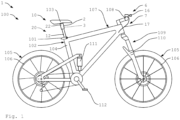
- the Figure 1 shows a bicycle 100 designed as a mountain bike with a bicycle component 1 according to the invention.
- the bicycle 100 can also be designed as a partially muscle-powered two-wheeler and, for example, as an e-bike.
- the bicycle 100 has two wheels 105, each of which is equipped with a hub and a rim 106.
- the bike 100 has full suspension.
- the fork is 109 designed as a suspension fork 110 and the frame 107 has a rear wheel damper 111.
- the bicycle 100 includes a saddle 103, a frame 107, a handlebar 108 and other bicycle components.
- the bicycle 100 here includes a derailleur gear 113.
- the bicycle 100 also has a braking device, not shown in detail.
- the bicycle component 1 includes an adjustable seat support device 2, which is accommodated here in a frame structure 102 designed as a seat tube 104.
- the seat support device 2 is fastened in the seat tube 104 by means of a seat tube clamp 101.
- the seat support device 2 is designed to be adjustable so that the saddle 103 can be fixed in different positions or saddle heights.
- the seat support device 2 here comprises two support elements 12, 22, which can be pulled apart or pushed into one another telescopically.
- the seat support device 2 is in a maximally extended first position 10.
- a lower saddle height can be set.
- the seat support device 2 is pushed into one another and brought into a maximally pushed-in second position 20, not shown here.
- the seat support device can also be adjusted into one or more intermediate positions.
- the bicycle component 1 To lock a set saddle position, the bicycle component 1 includes a locking device 3, which is not visible here arranged inside the seat support device 2. To release or activate the locking mechanism, there is one here Actuating device 6 is provided with an operating part 16 attached to the handlebar 108.
- the actuating device 6 here comprises a cable pull device 7 with a cable pull 17.
- the cable pull device 7 can include various components for guiding the cable pull 17 and, for example, deflection rollers or the like.
- the cable pull 17 runs here from the control part 16 into the frame 107 and there through the seat tube 104 into the seat support device 2 to the locking device 3.
- the cable 17 is tensioned with the control part 16 in order to release the locking device 3.
- the saddle can either be pressed deeper with the buttocks or moved upwards by lifting the buttocks with the support of a force storage device 9, not shown here.
- the seat support device 2 then locks in the respective position 10, 20. It is also possible for a stepless adjustment to be provided, so that e.g. B. when the control part 16 is released, the saddle 103 remains in a certain position.
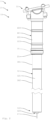
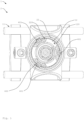
- FIGS. 2 to 5 show a bicycle component 1 according to the invention in various representations.
- the bicycle component 1 will be discussed below with reference to Figures 2 to 5 described in more detail.
- the bicycle component 1 comprises a seat support device 2 with a first or lower support element 12 and a second or upper support element 22.
- the two support elements 12, 22 are telescopic.
- the upper support element 22 is here equipped with a saddle holder 11, via which a saddle is attached to the Seat support device 2 can be mounted.
- the first support element 22 can be firmly attached to the frame structure of the bicycle.
- a seal 31 or an O-ring is arranged at the end of the upper support element 22 opposite the saddle receptacle 11. To accommodate the seal 31, the upper support element 22 has a collar.
- a dirt deflector 21 is arranged here at the end of the support element 22 opposite the saddle receptacle 11. This means that impurities are stripped off when immersed.
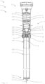
- the locking device 3 is here essentially arranged within the first support element 12.
- the locking device 3 here comprises a plurality of locking elements 4, of which only two can be seen here.
- the locking elements 4 are designed here as balls 14.
- a respective locking element 4 runs through a wall 121 of the first support element 12.
- the wall 121 has a through opening 303.
- the locking element 4 extends further into part of a wall 221 of the second support element 22.
- a recess 222 for the locking element 4 is incorporated there.
- the wall 221 is equipped with an outward-pointing projection 223.
- the recess 122 here is designed to be circumferential or ring-like. However, an embodiment is also possible in which a corresponding recess 202 20 is provided for each of the locking elements 4.
- the locking elements 4 are pressed into the recess 222 by a piston element 5 or by a cone 51 of the piston element 5. In this position, the locking elements 4 prevent the second or upper support element 22 from being able to lower further. The saddle height or the position of the two support elements 12, 22 relative to one another is thus locked. The piston element 5 and the locking elements 4 are in a locked or locked position. Here is the upper position 10 of the bicycle component 1 or the seat post or seat support device 2 shown. The locking elements 4 are locked in the lower recesses 222 of the second support element 22.
- the piston element 5 In order to release the locking device 3 and retract the seat support device 2, the piston element 5 is pulled downwards in the direction of the longitudinal axis of the support elements 12, 22. Then the piston element 5 is moved into a release position. In the release position, the saddle height can be reduced by applying appropriate pressure on the saddle, for example with the buttocks.
- the piston element 5 is conical here, so that it becomes narrower towards the upper end. If the piston element 5 is moved downwards, it no longer presses the locking elements 4 (via the cone 51) into the recess 222. This means that the upper support element 22 can slide over the lower support element 12.
- the locking device 3 In order to lock the saddle height in the retracted, lower position 20, the locking device 3 here comprises an additional, higher recess 222. There the locking elements 4 can be pressed in by the piston element 5, so that the saddle support device 2 is locked in this position.
- the bicycle component 1 here comprises a force storage device 9 designed as a spring 19, which is preloaded when the seat support device 2 is retracted.
- the spring 19 is designed as a compression spring.
- the locking device 3 is here equipped with a pretensioning device 8.
- the clamping device 8 here comprises a spring 18, which automatically presses the piston element 5 into the locked position.
- the piston element 5 is moved here with an actuating device 6 with a cable pull device 7 between the release position and the locked position.
- the piston element 5 is pulled downwards with a cable 17 of the cable pull device 7.
- the piston element 5 remains in the release position and the locking elements 4 are not pressed into the recess 222. If the cable 17 is relaxed, the pretensioning device 8 pushes the piston unit 5 back into the locked position.
- control panel 16 As with reference to Figure 1 described.
- the cable 17 runs here through the lower support element 12 and leaves it at one end 122, which can be received in the seat tube 104 of the bicycle 100.
- the cable pull 17 emerges from the support element at an axial end face 123 out of.
- the first support element 12 is here composed of two tubular support sections 301, 302 which are connected to one another in a connection region 300.
- the support sections 301, 302 are arranged in an overlapping manner in the connection area 300.
- the upper support section 301 in the operational state has a greater wall thickness than the lower support section 302.
- the through opening 303 for the locking elements 4 is located in the upper support section 301.
- the piston element 5 is guided in the upper support section 301.
- the first support element 12 here has an outer contour 120, which is matched to an inner contour 220 of the second support element.
- the outer contour 120 of the first support element 12 is provided here by the two support sections 301 and 302. In this way, the upper support element 22 can be pushed over the connection area 300 easily and without tilting.
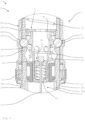
- an end position cushioning 23 is provided in the area of the upper end of the second support element 22 in the area of the upper end of the second support element 22, an end position cushioning 23 is provided. End position cushioning can also be provided at the lower end.
- the cable pull 17 is coupled to a cable tensioner 24. This means that the user always receives defined haptic feedback when touching or moving the actuating device.
- the cable tensioner 24 includes a pretensioning unit 25 and a sliding element 26, which is axially guided within the piston element.
- the sliding element is secured via the preload unit pressed into a pre-tensioned state and always keeps the rope taut.
- the two support elements 12, 22 have a substantially round outer contour 120 or inner contour 220.
- an anti-twist device 400 with three guide elements 401 is provided here.
- the guide elements 401 are arranged here between the two support elements 12, 22.
- the two support elements 12, 22 are connected to one another in a rotationally fixed manner.
- the seat support device 2 shown here can also include a damper device for damping the telescoping movement.
- the piston element 5 is then designed as a valve piston, which influences a flow of a damper fluid.
Landscapes
- Engineering & Computer Science (AREA)
- Mechanical Engineering (AREA)
- Motorcycle And Bicycle Frame (AREA)
- Steering Devices For Bicycles And Motorcycles (AREA)
Claims (15)
- Composant de bicyclette (1) pour une bicyclette (100) entraînée au moins en partie par force musculaire, comprenant un dispositif de support de selle (2) qui est réglable de manière télescopique entre au moins deux positions (10, 20) et destiné à adapter une hauteur de selle, ainsi qu'au moins un dispositif de verrouillage (3) destiné à arrêter le dispositif de support de selle (2) dans au moins l'une des positions (10, 20), dans lequel le dispositif de support de selle (2) comprend au moins deux éléments de support (12, 22) qui sont mobiles l'un par rapport à l'autre, à savoir un premier élément de support (12) et un deuxième élément de support (22), dans lequel le deuxième élément de support (22) sert à recevoir une selle (103), et dans lequel le premier élément de support (12) peut être fixé de manière solide à une structure de cadre de la bicyclette,
caractérisé par le fait
que le premier élément de support (12) est disposé au moins par sections à l'intérieur du deuxième élément de support (22) et que, pour télescoper le dispositif de support de selle (2), le deuxième élément de support (22) peut être déplacé au moins par sections sur le premier élément de support (12) et que le deuxième élément de support (22) est réalisé à paroi simple et que le dispositif de verrouillage (3) est disposé au moins en partie à l'intérieur du premier élément de support (12) et comprend au moins un élément de verrouillage (4), qui, à l'état arrêté, s'étend à travers au moins une paroi (121) du premier élément de support (12) jusque dans le deuxième élément de support (22). - Composant de bicyclette (1) selon la revendication précédente, dans lequel l'élément de verrouillage (4) comprend au moins une bille (14) ou est conçu en tant que telle.
- Composant de bicyclette (1) selon la revendication précédente, dans lequel, à l'état arrêté, l'élément de verrouillage (4) ne s'étend que dans une partie d'une paroi (221) du deuxième élément de support (22).
- Composant de bicyclette (1) selon l'une quelconque des deux revendications précédentes, dans lequel le dispositif de verrouillage (3) est adapté et conçu pour pousser l'élément de verrouillage (4) au moins en partie, au moyen d'au moins un élément de piston (5), dans au moins un évidement (222) du deuxième élément de support, et dans lequel en particulier l'élément de piston (5) peut être déplacé en direction de l'axe longitudinal du premier élément de support (12) dans au moins une position de libération et dans lequel, dans la position de libération, l'élément de piston (5) ne pousse pas l'élément de verrouillage (4) dans le deuxième élément de support (22).
- Composant de bicyclette (1) selon la revendication précédente, dans lequel, pour prendre la position de libération, l'élément de piston (5) peut être déplacé, en particulier par une traction, en direction d'une extrémité (122) du premier élément de support (12) qui est opposée au deuxième élément de support.
- Composant de bicyclette (1) selon l'une quelconque des revendications précédentes, comprenant au moins un dispositif d'actionnement (6) pour libérer et/ou activer le dispositif de verrouillage (3) et dans lequel le dispositif d'actionnement (6) est réalisé au moins en partie mécaniquement et comprend au moins un dispositif de traction par câble (7) ayant au moins un câble de commande (17).
- Composant de bicyclette (1) selon la revendication précédente, dans lequel le câble de commande (17) sort d'une face frontale axiale (123) du premier élément de support (12).
- Composant de bicyclette (1) selon l'une quelconque des deux revendications précédentes, dans lequel le câble de commande est couplé à un tendeur de câble.
- Composant de bicyclette (1) selon l'une quelconque des revendications précédentes, dans lequel au moins un dispositif de stockage d'énergie (9) est disposé à l'intérieur du deuxième élément de support (22) et dans lequel le dispositif de stockage d'énergie (9) est adapté et conçu pour être chargé au moins en partie par le fait que le premier élément de support (12) entre dans le deuxième élément de support (22) et pour être déchargé au moins en partie par le fait que le premier élément de support (12) sort du deuxième élément de support (22), de sorte que le dispositif de support de selle (2) peut être sorti au moins en partie automatiquement.
- Composant de bicyclette (1) selon l'une quelconque des revendications précédentes, dans lequel le premier élément de support (12) et/ou le deuxième élément de support (22) est constitué au moins pour une partie importante d'un matériau composite fibreux.
- Composant de bicyclette (1) selon l'une quelconque des revendications précédentes, dans lequel le premier élément de support (12) comprend au moins deux sections de support tubulaires (301, 302) qui sont reliées solidement l'une à l'autre dans une zone de liaison (300) et sont de préférence collées.
- Composant de bicyclette (1) selon la revendication précédente, dans lequel l'une (301) des sections de support présente, au moins par sections, une épaisseur de paroi supérieure à celle de l'autre section de support (302) et au moins une ouverture de passage (303) pour l'élément de verrouillage (4).
- Composant de bicyclette (1) selon l'une quelconque des deux revendications précédentes, dans lequel l'une (301) des sections de support est constituée au moins pour une partie importante d'un matériau composite fibreux et/ou dans lequel l'autre section de support (302) est constituée au moins pour une partie importante d'un matériau de construction métallique léger et en particulier d'un matériau d'aluminium.
- Composant de bicyclette (1) selon l'une quelconque des revendications précédentes, dans lequel une course maximale du dispositif de support de selle (2) est de 100 mm et de préférence de 80 mm.
- Bicyclette (100), qui peut être entraînée, au moins en partie, par force musculaire, comprenant au moins un composant de bicyclette (1) selon l'une quelconque des revendications précédentes.
Applications Claiming Priority (1)
| Application Number | Priority Date | Filing Date | Title |
|---|---|---|---|
| DE102017118417.1A DE102017118417A1 (de) | 2017-08-11 | 2017-08-11 | Fahrradkomponente |
Publications (2)
| Publication Number | Publication Date |
|---|---|
| EP3441292A1 EP3441292A1 (fr) | 2019-02-13 |
| EP3441292B1 true EP3441292B1 (fr) | 2024-01-17 |
Family
ID=63144886
Family Applications (1)
| Application Number | Title | Priority Date | Filing Date |
|---|---|---|---|
| EP18187248.2A Active EP3441292B1 (fr) | 2017-08-11 | 2018-08-03 | Composants de bicyclette |
Country Status (3)
| Country | Link |
|---|---|
| US (1) | US10689049B2 (fr) |
| EP (1) | EP3441292B1 (fr) |
| DE (1) | DE102017118417A1 (fr) |
Families Citing this family (14)
| Publication number | Priority date | Publication date | Assignee | Title |
|---|---|---|---|---|
| CZ307998B6 (cs) * | 2018-02-05 | 2019-10-09 | KRIŠLO, Michal | Sestava pro odpružení sedla jízdního kola a sedlo jízdního kola s touto sestavou |
| US10919592B2 (en) | 2018-04-06 | 2021-02-16 | Specialized Bicycle Components, Inc. | Bicycle with compliant seat post interface |
| US11447201B2 (en) * | 2019-01-31 | 2022-09-20 | Fox Factory, Inc. | Dropper seatpost head assembly |
| JP6742496B1 (ja) * | 2019-12-24 | 2020-08-19 | 有限会社藤原ホイル | サドル昇降装置 |
| TWM598260U (zh) * | 2020-01-10 | 2020-07-11 | 信隆車料工業股份有限公司 | 可調式避震座管 |
| US12441421B2 (en) | 2020-04-24 | 2025-10-14 | Dt Swiss Inc. | Bicycle component with an adjustable seat post device |
| DE102020111306A1 (de) | 2020-04-24 | 2021-10-28 | Dt Swiss Ag | Fahrradkomponente mit einer verstellbaren Sattelstützeinrichtung |
| EP4168297A1 (fr) * | 2020-06-23 | 2023-04-26 | Upturn Studio Spolka z Ograniczona Odpowiedzialnoscia | Cadre de bicyclette à géométrie variable et procédé de modification dynamique de la géométrie d'un cadre de bicyclette |
| TWM618794U (zh) * | 2020-10-22 | 2021-11-01 | 立盟工業有限公司 | 自行車座桿結構 |
| WO2022204158A1 (fr) * | 2021-03-26 | 2022-09-29 | The Hive Global, Inc. | Tige de selle de bicyclette télescopique à hauteur réglable et insertion de cadre fixe |
| IT202100007997A1 (it) * | 2021-03-31 | 2022-10-01 | Angelo Morelli | Reggisella telescopico |
| CN114228879B (zh) * | 2022-01-25 | 2022-12-09 | 杭州新兴车料有限公司 | 一种自行车车架用减震装置 |
| TWM636822U (zh) * | 2022-08-29 | 2023-01-21 | 巨大機械工業股份有限公司 | 伸縮機構 |
| TWI905731B (zh) * | 2023-05-04 | 2025-11-21 | 巨大機械工業股份有限公司 | 座桿、自行車及行程墊塊安裝方法 |
Citations (1)
| Publication number | Priority date | Publication date | Assignee | Title |
|---|---|---|---|---|
| CN2173745Y (zh) * | 1993-09-16 | 1994-08-10 | 舒长河 | 自行车坐垫升降减震器 |
Family Cites Families (12)
| Publication number | Priority date | Publication date | Assignee | Title |
|---|---|---|---|---|
| FR2775650A1 (fr) * | 1998-03-06 | 1999-09-10 | Alexis Defarge | Suspension de selle de velo reglable |
| US7204466B2 (en) * | 2005-03-11 | 2007-04-17 | Wu-Hong Hsieh | Quick-acting telescopic tube |
| US8079772B1 (en) * | 2006-12-21 | 2011-12-20 | Brennan James S | Multi-position bicycle seat post assembly |
| DE102007063365A1 (de) * | 2007-12-29 | 2009-07-02 | Marzell Maier | Vorrichtung zur Höhenverstellung einer Sattelstütze |
| JP2014508069A (ja) * | 2011-03-11 | 2014-04-03 | スペシャライズド バイシクル コンポーネンツ インコーポレイテッド | 自転車用の調整可能組立体 |
| US8894025B2 (en) * | 2012-08-30 | 2014-11-25 | Tien Hsin Industries Co., Ltd. | Multi-position adjustable height seat post |
| US9481420B2 (en) * | 2013-08-01 | 2016-11-01 | Specialized Bicycle Components, Inc. | Saddle adjustment system |
| US10562578B2 (en) * | 2015-04-15 | 2020-02-18 | Specialized Bicycle Components, Inc. | Adjustable saddle post system |
| AT517510B1 (de) | 2015-07-21 | 2022-11-15 | Lukas Eberlberger | Positioniervorrichtung mit Teleskopelement und Stützelement |
| GB2566636B (en) * | 2016-07-08 | 2021-10-13 | Schlanger Raphael | Height adjustable seatpost assembly |
| US20180134337A1 (en) * | 2016-11-16 | 2018-05-17 | Barry Lyn Holtzman | Bicycle seat post assembly |
| ES1185933Y (es) * | 2017-06-06 | 2017-09-14 | Bages Estopa Ricard | Tija telescopica para bicicletas |
-
2017
- 2017-08-11 DE DE102017118417.1A patent/DE102017118417A1/de not_active Withdrawn
-
2018
- 2018-08-03 EP EP18187248.2A patent/EP3441292B1/fr active Active
- 2018-08-10 US US16/100,509 patent/US10689049B2/en active Active
Patent Citations (1)
| Publication number | Priority date | Publication date | Assignee | Title |
|---|---|---|---|---|
| CN2173745Y (zh) * | 1993-09-16 | 1994-08-10 | 舒长河 | 自行车坐垫升降减震器 |
Also Published As
| Publication number | Publication date |
|---|---|
| DE102017118417A1 (de) | 2019-02-14 |
| US10689049B2 (en) | 2020-06-23 |
| US20190047649A1 (en) | 2019-02-14 |
| EP3441292A1 (fr) | 2019-02-13 |
Similar Documents
| Publication | Publication Date | Title |
|---|---|---|
| EP3441292B1 (fr) | Composants de bicyclette | |
| EP3901013B1 (fr) | Composant de bicyclette pourvu de dispositif de tige de selle réglable | |
| EP3403910B1 (fr) | Dispositif de traction, en particulier pour une bicyclette | |
| DE102010044356B4 (de) | Höhenverstellbare Sattelstütze | |
| DE102008059894B4 (de) | Höhenverstellbare Sattelstütze | |
| DE102007063365A1 (de) | Vorrichtung zur Höhenverstellung einer Sattelstütze | |
| DE102019006320B3 (de) | Sattellift für Fahrräder | |
| DE102015101368A1 (de) | Fahrradsattelstützenanordnung | |
| EP3412928B1 (fr) | Dispositif d'amortissment traction, en particulier pour une bicyclette | |
| EP3275693B1 (fr) | Moyeu, en particulier pour vélos | |
| DE202011103814U1 (de) | Doppelbrücken-Fahrradgabel | |
| DE102019117929A1 (de) | Bremssystem mit Feststellbremsvorrichtung | |
| EP2551178A1 (fr) | Fourche de vélo avec unité de freinage | |
| EP3325333B1 (fr) | Tige de selle télescopique pour cadre de bicyclette | |
| DE202015106650U1 (de) | Schnellspann-Steckachse für Zweiräder | |
| DE9013266U1 (de) | Zweirad mit einem höhenverstellbaren Sattel | |
| EP4159602B1 (fr) | Élément de bicyclette doté d'un agencement de support de selle réglable | |
| DE102013008529B3 (de) | Sattelstütze für Fahrräder | |
| DE102008006242A1 (de) | Tretroller, Skateboard oder ähnliches Fahrzeug mit einstellbarer Lenkung | |
| DE102020006209B3 (de) | Hydraulische Zweiradbremse | |
| DE10036379C1 (de) | Verstellbare Halterung für einen Fahrradsattel | |
| DE202010010877U1 (de) | Höhenverstellbare Sattelstütze | |
| EP4477520B1 (fr) | Ensemble frein hydraulique pour bicyclette entraînée au moins partiellement par la force musculaire | |
| DE102013106899A1 (de) | Lenkkopflager | |
| DE19849178C1 (de) | Vorrichtung zur Sattellagenverstellung an einem Zweirad, insbesondere einem Fahrrad |
Legal Events
| Date | Code | Title | Description |
|---|---|---|---|
| PUAI | Public reference made under article 153(3) epc to a published international application that has entered the european phase |
Free format text: ORIGINAL CODE: 0009012 |
|
| STAA | Information on the status of an ep patent application or granted ep patent |
Free format text: STATUS: THE APPLICATION HAS BEEN PUBLISHED |
|
| AK | Designated contracting states |
Kind code of ref document: A1 Designated state(s): AL AT BE BG CH CY CZ DE DK EE ES FI FR GB GR HR HU IE IS IT LI LT LU LV MC MK MT NL NO PL PT RO RS SE SI SK SM TR |
|
| AX | Request for extension of the european patent |
Extension state: BA ME |
|
| STAA | Information on the status of an ep patent application or granted ep patent |
Free format text: STATUS: REQUEST FOR EXAMINATION WAS MADE |
|
| 17P | Request for examination filed |
Effective date: 20190808 |
|
| RBV | Designated contracting states (corrected) |
Designated state(s): AL AT BE BG CH CY CZ DE DK EE ES FI FR GB GR HR HU IE IS IT LI LT LU LV MC MK MT NL NO PL PT RO RS SE SI SK SM TR |
|
| STAA | Information on the status of an ep patent application or granted ep patent |
Free format text: STATUS: EXAMINATION IS IN PROGRESS |
|
| 17Q | First examination report despatched |
Effective date: 20200408 |
|
| RIC1 | Information provided on ipc code assigned before grant |
Ipc: B62J 1/08 20060101AFI20210211BHEP |
|
| P01 | Opt-out of the competence of the unified patent court (upc) registered |
Effective date: 20230517 |
|
| GRAP | Despatch of communication of intention to grant a patent |
Free format text: ORIGINAL CODE: EPIDOSNIGR1 |
|
| STAA | Information on the status of an ep patent application or granted ep patent |
Free format text: STATUS: GRANT OF PATENT IS INTENDED |
|
| INTG | Intention to grant announced |
Effective date: 20230823 |
|
| GRAS | Grant fee paid |
Free format text: ORIGINAL CODE: EPIDOSNIGR3 |
|
| GRAA | (expected) grant |
Free format text: ORIGINAL CODE: 0009210 |
|
| STAA | Information on the status of an ep patent application or granted ep patent |
Free format text: STATUS: THE PATENT HAS BEEN GRANTED |
|
| AK | Designated contracting states |
Kind code of ref document: B1 Designated state(s): AL AT BE BG CH CY CZ DE DK EE ES FI FR GB GR HR HU IE IS IT LI LT LU LV MC MK MT NL NO PL PT RO RS SE SI SK SM TR |
|
| REG | Reference to a national code |
Ref country code: GB Ref legal event code: FG4D Free format text: NOT ENGLISH |
|
| REG | Reference to a national code |
Ref country code: CH Ref legal event code: EP |
|
| REG | Reference to a national code |
Ref country code: DE Ref legal event code: R096 Ref document number: 502018013986 Country of ref document: DE |
|
| REG | Reference to a national code |
Ref country code: IE Ref legal event code: FG4D Free format text: LANGUAGE OF EP DOCUMENT: GERMAN |
|
| REG | Reference to a national code |
Ref country code: LT Ref legal event code: MG9D |
|
| REG | Reference to a national code |
Ref country code: NL Ref legal event code: MP Effective date: 20240117 |
|
| PG25 | Lapsed in a contracting state [announced via postgrant information from national office to epo] |
Ref country code: NL Free format text: LAPSE BECAUSE OF FAILURE TO SUBMIT A TRANSLATION OF THE DESCRIPTION OR TO PAY THE FEE WITHIN THE PRESCRIBED TIME-LIMIT Effective date: 20240117 |
|
| PG25 | Lapsed in a contracting state [announced via postgrant information from national office to epo] |
Ref country code: NL Free format text: LAPSE BECAUSE OF FAILURE TO SUBMIT A TRANSLATION OF THE DESCRIPTION OR TO PAY THE FEE WITHIN THE PRESCRIBED TIME-LIMIT Effective date: 20240117 |
|
| PG25 | Lapsed in a contracting state [announced via postgrant information from national office to epo] |
Ref country code: IS Free format text: LAPSE BECAUSE OF FAILURE TO SUBMIT A TRANSLATION OF THE DESCRIPTION OR TO PAY THE FEE WITHIN THE PRESCRIBED TIME-LIMIT Effective date: 20240517 |
|
| PG25 | Lapsed in a contracting state [announced via postgrant information from national office to epo] |
Ref country code: LT Free format text: LAPSE BECAUSE OF FAILURE TO SUBMIT A TRANSLATION OF THE DESCRIPTION OR TO PAY THE FEE WITHIN THE PRESCRIBED TIME-LIMIT Effective date: 20240117 |
|
| PG25 | Lapsed in a contracting state [announced via postgrant information from national office to epo] |
Ref country code: GR Free format text: LAPSE BECAUSE OF FAILURE TO SUBMIT A TRANSLATION OF THE DESCRIPTION OR TO PAY THE FEE WITHIN THE PRESCRIBED TIME-LIMIT Effective date: 20240418 |
|
| PG25 | Lapsed in a contracting state [announced via postgrant information from national office to epo] |
Ref country code: HR Free format text: LAPSE BECAUSE OF FAILURE TO SUBMIT A TRANSLATION OF THE DESCRIPTION OR TO PAY THE FEE WITHIN THE PRESCRIBED TIME-LIMIT Effective date: 20240117 Ref country code: RS Free format text: LAPSE BECAUSE OF FAILURE TO SUBMIT A TRANSLATION OF THE DESCRIPTION OR TO PAY THE FEE WITHIN THE PRESCRIBED TIME-LIMIT Effective date: 20240417 |
|
| PG25 | Lapsed in a contracting state [announced via postgrant information from national office to epo] |
Ref country code: ES Free format text: LAPSE BECAUSE OF FAILURE TO SUBMIT A TRANSLATION OF THE DESCRIPTION OR TO PAY THE FEE WITHIN THE PRESCRIBED TIME-LIMIT Effective date: 20240117 |
|
| PG25 | Lapsed in a contracting state [announced via postgrant information from national office to epo] |
Ref country code: RS Free format text: LAPSE BECAUSE OF FAILURE TO SUBMIT A TRANSLATION OF THE DESCRIPTION OR TO PAY THE FEE WITHIN THE PRESCRIBED TIME-LIMIT Effective date: 20240417 Ref country code: NO Free format text: LAPSE BECAUSE OF FAILURE TO SUBMIT A TRANSLATION OF THE DESCRIPTION OR TO PAY THE FEE WITHIN THE PRESCRIBED TIME-LIMIT Effective date: 20240417 Ref country code: LT Free format text: LAPSE BECAUSE OF FAILURE TO SUBMIT A TRANSLATION OF THE DESCRIPTION OR TO PAY THE FEE WITHIN THE PRESCRIBED TIME-LIMIT Effective date: 20240117 Ref country code: IS Free format text: LAPSE BECAUSE OF FAILURE TO SUBMIT A TRANSLATION OF THE DESCRIPTION OR TO PAY THE FEE WITHIN THE PRESCRIBED TIME-LIMIT Effective date: 20240517 Ref country code: HR Free format text: LAPSE BECAUSE OF FAILURE TO SUBMIT A TRANSLATION OF THE DESCRIPTION OR TO PAY THE FEE WITHIN THE PRESCRIBED TIME-LIMIT Effective date: 20240117 Ref country code: GR Free format text: LAPSE BECAUSE OF FAILURE TO SUBMIT A TRANSLATION OF THE DESCRIPTION OR TO PAY THE FEE WITHIN THE PRESCRIBED TIME-LIMIT Effective date: 20240418 Ref country code: FI Free format text: LAPSE BECAUSE OF FAILURE TO SUBMIT A TRANSLATION OF THE DESCRIPTION OR TO PAY THE FEE WITHIN THE PRESCRIBED TIME-LIMIT Effective date: 20240117 Ref country code: ES Free format text: LAPSE BECAUSE OF FAILURE TO SUBMIT A TRANSLATION OF THE DESCRIPTION OR TO PAY THE FEE WITHIN THE PRESCRIBED TIME-LIMIT Effective date: 20240117 Ref country code: BG Free format text: LAPSE BECAUSE OF FAILURE TO SUBMIT A TRANSLATION OF THE DESCRIPTION OR TO PAY THE FEE WITHIN THE PRESCRIBED TIME-LIMIT Effective date: 20240117 |
|
| PG25 | Lapsed in a contracting state [announced via postgrant information from national office to epo] |
Ref country code: PL Free format text: LAPSE BECAUSE OF FAILURE TO SUBMIT A TRANSLATION OF THE DESCRIPTION OR TO PAY THE FEE WITHIN THE PRESCRIBED TIME-LIMIT Effective date: 20240117 Ref country code: PT Free format text: LAPSE BECAUSE OF FAILURE TO SUBMIT A TRANSLATION OF THE DESCRIPTION OR TO PAY THE FEE WITHIN THE PRESCRIBED TIME-LIMIT Effective date: 20240517 |
|
| PG25 | Lapsed in a contracting state [announced via postgrant information from national office to epo] |
Ref country code: SE Free format text: LAPSE BECAUSE OF FAILURE TO SUBMIT A TRANSLATION OF THE DESCRIPTION OR TO PAY THE FEE WITHIN THE PRESCRIBED TIME-LIMIT Effective date: 20240117 Ref country code: PT Free format text: LAPSE BECAUSE OF FAILURE TO SUBMIT A TRANSLATION OF THE DESCRIPTION OR TO PAY THE FEE WITHIN THE PRESCRIBED TIME-LIMIT Effective date: 20240517 Ref country code: PL Free format text: LAPSE BECAUSE OF FAILURE TO SUBMIT A TRANSLATION OF THE DESCRIPTION OR TO PAY THE FEE WITHIN THE PRESCRIBED TIME-LIMIT Effective date: 20240117 Ref country code: LV Free format text: LAPSE BECAUSE OF FAILURE TO SUBMIT A TRANSLATION OF THE DESCRIPTION OR TO PAY THE FEE WITHIN THE PRESCRIBED TIME-LIMIT Effective date: 20240117 |
|
| PG25 | Lapsed in a contracting state [announced via postgrant information from national office to epo] |
Ref country code: DK Free format text: LAPSE BECAUSE OF FAILURE TO SUBMIT A TRANSLATION OF THE DESCRIPTION OR TO PAY THE FEE WITHIN THE PRESCRIBED TIME-LIMIT Effective date: 20240117 |
|
| PG25 | Lapsed in a contracting state [announced via postgrant information from national office to epo] |
Ref country code: SM Free format text: LAPSE BECAUSE OF FAILURE TO SUBMIT A TRANSLATION OF THE DESCRIPTION OR TO PAY THE FEE WITHIN THE PRESCRIBED TIME-LIMIT Effective date: 20240117 |
|
| REG | Reference to a national code |
Ref country code: DE Ref legal event code: R097 Ref document number: 502018013986 Country of ref document: DE |
|
| PG25 | Lapsed in a contracting state [announced via postgrant information from national office to epo] |
Ref country code: EE Free format text: LAPSE BECAUSE OF FAILURE TO SUBMIT A TRANSLATION OF THE DESCRIPTION OR TO PAY THE FEE WITHIN THE PRESCRIBED TIME-LIMIT Effective date: 20240117 Ref country code: CZ Free format text: LAPSE BECAUSE OF FAILURE TO SUBMIT A TRANSLATION OF THE DESCRIPTION OR TO PAY THE FEE WITHIN THE PRESCRIBED TIME-LIMIT Effective date: 20240117 |
|
| PG25 | Lapsed in a contracting state [announced via postgrant information from national office to epo] |
Ref country code: SK Free format text: LAPSE BECAUSE OF FAILURE TO SUBMIT A TRANSLATION OF THE DESCRIPTION OR TO PAY THE FEE WITHIN THE PRESCRIBED TIME-LIMIT Effective date: 20240117 |
|
| PG25 | Lapsed in a contracting state [announced via postgrant information from national office to epo] |
Ref country code: SM Free format text: LAPSE BECAUSE OF FAILURE TO SUBMIT A TRANSLATION OF THE DESCRIPTION OR TO PAY THE FEE WITHIN THE PRESCRIBED TIME-LIMIT Effective date: 20240117 Ref country code: SK Free format text: LAPSE BECAUSE OF FAILURE TO SUBMIT A TRANSLATION OF THE DESCRIPTION OR TO PAY THE FEE WITHIN THE PRESCRIBED TIME-LIMIT Effective date: 20240117 Ref country code: RO Free format text: LAPSE BECAUSE OF FAILURE TO SUBMIT A TRANSLATION OF THE DESCRIPTION OR TO PAY THE FEE WITHIN THE PRESCRIBED TIME-LIMIT Effective date: 20240117 Ref country code: EE Free format text: LAPSE BECAUSE OF FAILURE TO SUBMIT A TRANSLATION OF THE DESCRIPTION OR TO PAY THE FEE WITHIN THE PRESCRIBED TIME-LIMIT Effective date: 20240117 Ref country code: DK Free format text: LAPSE BECAUSE OF FAILURE TO SUBMIT A TRANSLATION OF THE DESCRIPTION OR TO PAY THE FEE WITHIN THE PRESCRIBED TIME-LIMIT Effective date: 20240117 Ref country code: CZ Free format text: LAPSE BECAUSE OF FAILURE TO SUBMIT A TRANSLATION OF THE DESCRIPTION OR TO PAY THE FEE WITHIN THE PRESCRIBED TIME-LIMIT Effective date: 20240117 |
|
| PLBE | No opposition filed within time limit |
Free format text: ORIGINAL CODE: 0009261 |
|
| STAA | Information on the status of an ep patent application or granted ep patent |
Free format text: STATUS: NO OPPOSITION FILED WITHIN TIME LIMIT |
|
| PG25 | Lapsed in a contracting state [announced via postgrant information from national office to epo] |
Ref country code: IT Free format text: LAPSE BECAUSE OF FAILURE TO SUBMIT A TRANSLATION OF THE DESCRIPTION OR TO PAY THE FEE WITHIN THE PRESCRIBED TIME-LIMIT Effective date: 20240117 |
|
| 26N | No opposition filed |
Effective date: 20241018 |
|
| PG25 | Lapsed in a contracting state [announced via postgrant information from national office to epo] |
Ref country code: IT Free format text: LAPSE BECAUSE OF FAILURE TO SUBMIT A TRANSLATION OF THE DESCRIPTION OR TO PAY THE FEE WITHIN THE PRESCRIBED TIME-LIMIT Effective date: 20240117 |
|
| REG | Reference to a national code |
Ref country code: CH Ref legal event code: PL |
|
| PG25 | Lapsed in a contracting state [announced via postgrant information from national office to epo] |
Ref country code: LU Free format text: LAPSE BECAUSE OF NON-PAYMENT OF DUE FEES Effective date: 20240803 |
|
| GBPC | Gb: european patent ceased through non-payment of renewal fee |
Effective date: 20240803 |
|
| PG25 | Lapsed in a contracting state [announced via postgrant information from national office to epo] |
Ref country code: SI Free format text: LAPSE BECAUSE OF FAILURE TO SUBMIT A TRANSLATION OF THE DESCRIPTION OR TO PAY THE FEE WITHIN THE PRESCRIBED TIME-LIMIT Effective date: 20240117 Ref country code: MC Free format text: LAPSE BECAUSE OF FAILURE TO SUBMIT A TRANSLATION OF THE DESCRIPTION OR TO PAY THE FEE WITHIN THE PRESCRIBED TIME-LIMIT Effective date: 20240117 Ref country code: CH Free format text: LAPSE BECAUSE OF NON-PAYMENT OF DUE FEES Effective date: 20240831 |
|
| REG | Reference to a national code |
Ref country code: BE Ref legal event code: MM Effective date: 20240831 |
|
| PG25 | Lapsed in a contracting state [announced via postgrant information from national office to epo] |
Ref country code: GB Free format text: LAPSE BECAUSE OF NON-PAYMENT OF DUE FEES Effective date: 20240803 |
|
| PG25 | Lapsed in a contracting state [announced via postgrant information from national office to epo] |
Ref country code: BE Free format text: LAPSE BECAUSE OF NON-PAYMENT OF DUE FEES Effective date: 20240831 |
|
| PG25 | Lapsed in a contracting state [announced via postgrant information from national office to epo] |
Ref country code: FR Free format text: LAPSE BECAUSE OF NON-PAYMENT OF DUE FEES Effective date: 20240831 |
|
| PG25 | Lapsed in a contracting state [announced via postgrant information from national office to epo] |
Ref country code: IE Free format text: LAPSE BECAUSE OF NON-PAYMENT OF DUE FEES Effective date: 20240803 |
|
| PGFP | Annual fee paid to national office [announced via postgrant information from national office to epo] |
Ref country code: DE Payment date: 20250919 Year of fee payment: 8 |
|
| REG | Reference to a national code |
Ref country code: AT Ref legal event code: MM01 Ref document number: 1650383 Country of ref document: AT Kind code of ref document: T Effective date: 20240803 |
|
| PG25 | Lapsed in a contracting state [announced via postgrant information from national office to epo] |
Ref country code: AT Free format text: LAPSE BECAUSE OF NON-PAYMENT OF DUE FEES Effective date: 20240803 |
|
| PG25 | Lapsed in a contracting state [announced via postgrant information from national office to epo] |
Ref country code: CY Free format text: LAPSE BECAUSE OF FAILURE TO SUBMIT A TRANSLATION OF THE DESCRIPTION OR TO PAY THE FEE WITHIN THE PRESCRIBED TIME-LIMIT; INVALID AB INITIO Effective date: 20180803 |
|
| PG25 | Lapsed in a contracting state [announced via postgrant information from national office to epo] |
Ref country code: HU Free format text: LAPSE BECAUSE OF FAILURE TO SUBMIT A TRANSLATION OF THE DESCRIPTION OR TO PAY THE FEE WITHIN THE PRESCRIBED TIME-LIMIT; INVALID AB INITIO Effective date: 20180803 |