EP3441292A1 - Composants de bicyclette - Google Patents
Composants de bicyclette Download PDFInfo
- Publication number
- EP3441292A1 EP3441292A1 EP18187248.2A EP18187248A EP3441292A1 EP 3441292 A1 EP3441292 A1 EP 3441292A1 EP 18187248 A EP18187248 A EP 18187248A EP 3441292 A1 EP3441292 A1 EP 3441292A1
- Authority
- EP
- European Patent Office
- Prior art keywords
- support
- support element
- bicycle component
- locking
- bicycle
- Prior art date
- Legal status (The legal status is an assumption and is not a legal conclusion. Google has not performed a legal analysis and makes no representation as to the accuracy of the status listed.)
- Granted
Links
Images


Classifications
-
- B—PERFORMING OPERATIONS; TRANSPORTING
- B62—LAND VEHICLES FOR TRAVELLING OTHERWISE THAN ON RAILS
- B62J—CYCLE SADDLES OR SEATS; AUXILIARY DEVICES OR ACCESSORIES SPECIALLY ADAPTED TO CYCLES AND NOT OTHERWISE PROVIDED FOR, e.g. ARTICLE CARRIERS OR CYCLE PROTECTORS
- B62J1/00—Saddles or other seats for cycles; Arrangement thereof; Component parts
- B62J1/08—Frames for saddles; Connections between saddle frames and seat pillars; Seat pillars
-
- B—PERFORMING OPERATIONS; TRANSPORTING
- B62—LAND VEHICLES FOR TRAVELLING OTHERWISE THAN ON RAILS
- B62J—CYCLE SADDLES OR SEATS; AUXILIARY DEVICES OR ACCESSORIES SPECIALLY ADAPTED TO CYCLES AND NOT OTHERWISE PROVIDED FOR, e.g. ARTICLE CARRIERS OR CYCLE PROTECTORS
- B62J1/00—Saddles or other seats for cycles; Arrangement thereof; Component parts
- B62J1/02—Saddles resiliently mounted on the frame; Equipment therefor, e.g. springs
- B62J1/06—Saddles capable of parallel motion up and down
-
- B—PERFORMING OPERATIONS; TRANSPORTING
- B62—LAND VEHICLES FOR TRAVELLING OTHERWISE THAN ON RAILS
- B62K—CYCLES; CYCLE FRAMES; CYCLE STEERING DEVICES; RIDER-OPERATED TERMINAL CONTROLS SPECIALLY ADAPTED FOR CYCLES; CYCLE AXLE SUSPENSIONS; CYCLE SIDECARS, FORECARS, OR THE LIKE
- B62K19/00—Cycle frames
- B62K19/30—Frame parts shaped to receive other cycle parts or accessories
- B62K19/36—Frame parts shaped to receive other cycle parts or accessories for attaching saddle pillars, e.g. adjustable during ride
-
- B—PERFORMING OPERATIONS; TRANSPORTING
- B62—LAND VEHICLES FOR TRAVELLING OTHERWISE THAN ON RAILS
- B62J—CYCLE SADDLES OR SEATS; AUXILIARY DEVICES OR ACCESSORIES SPECIALLY ADAPTED TO CYCLES AND NOT OTHERWISE PROVIDED FOR, e.g. ARTICLE CARRIERS OR CYCLE PROTECTORS
- B62J1/00—Saddles or other seats for cycles; Arrangement thereof; Component parts
- B62J1/08—Frames for saddles; Connections between saddle frames and seat pillars; Seat pillars
- B62J2001/085—Seat pillars having mechanisms to vary seat height, independently of the cycle frame
Definitions
- the present invention relates to a bicycle component for an at least partially powered by muscle power bicycle with a telescopically adjustable between at least two positions seat post for adjusting a saddle height.
- the saddle when riding downhill, the saddle must be low enough so that the rider can put his weight behind the saddle to shift the center of gravity to the rear.
- the saddle height When driving in the sitting position, the saddle height must be ergonomically adjusted to allow a favorable force input into the drive.
- adjustable seat posts which are also referred to as telescopic supports.
- telescopic supports two telescoping tubes are used, the thicker tube is inserted into the bottom of the frame and the thinner tube protrudes upwards from the thicker tube.
- the driver can operate the adjustment mechanism of the seat post usually from the handlebar. This allows adjustment of the saddle height while driving without the driver having to dismount.
- Hydraulic seat posts allow adjustment in a variety of height positions. However, one drawback to this is that they are difficult to disassemble and clean and maintain. Special tools are required for disassembly. In addition, hydraulic fluid can escape if the disassembly is not professional.
- the known adjustable seatposts generally work satisfactorily, but also offer room for improvement.
- the known solutions can be optimized in terms of their practicality and their weight and their production costs and in particular the maintenance costs.
- an adjustable seat post is to be made available, which is reliable and uncomplicated and is economical to produce and in particular easy to maintain.
- the bicycle component according to the invention is intended for a bicycle operated at least partially by muscle power.
- the Bicycle component includes a telescopically adjustable seat post between at least two positions for adjusting a saddle height.
- the bicycle component comprises at least one locking device for locking the seat post in at least one of the positions.
- the seat post comprises at least two relatively movable support members, namely, the first support member and at least one second support member.
- the first support member may be attachable to or formed on a frame structure of the bicycle.
- the second support element serves to receive a saddle. In this case, the first support element is at least partially disposed within the second support member. For telescoping the seat post, the second support element is at least partially movable over the first support member.
- Such an "upside-down" design allows a very simple structure.
- the second support element slides on a height adjustment (of a saddle) on the first support element and / or is guided by the first support element.
- the bicycle component according to the invention offers many advantages.
- a significant advantage provides the inventive arrangement of the two support elements.
- the second or upper support element can be structurally designed independently of the frame structure and in particular of the seat tube diameter. This results in significantly higher degrees of freedom for the design and considerably more flexible design options in order to obtain a reliable and cost-optimized seat post.
- the bicycle component according to the invention can be used particularly well as a mountain bike for other types of bicycles, z. For example, racing bikes, cyclo-cross bikes and trekking bikes and e-bikes.
- significantly larger diameters for the second and upper support members are possible with the invention. This also results in a freer choice of material of the support elements.
- the bicycle component according to the invention therefore also allows an advantageous weight reduction, which is particularly advantageous in sports bikes.
- Another advantage is that there are higher degrees of freedom for the mounting of the saddle on the second support element. So far, the upper part of telescopic seat posts could be constructed only within very narrow limits, as this had to have a particularly small diameter to fit when retracting the saddle in the lower part. The lower part could not be easily enlarged, because this in turn must fit into the seat tube of the frame.
- the first support element consists of a lightweight material. It is possible that the first and / or the second support element consists at least partially or completely of a fiber-reinforced material such as a carbon material. Particularly preferably, the first support element consists at least partially and in particular at least to a considerable extent or essentially completely or completely of (at least) one fiber composite material.
- the wall thickness of the first support member can be designed independently of the dimensions of the upper support member.
- the first or lower support member can be performed for example in an optimal lightweight construction. So far, the lower part of telescopic seat post had to be made so thin-walled that the upper part could dip so that telescoping is possible.
- the lower support element can be made so large, for example, that it fits perfectly into the seat tube. This results in a total considerably stiffer and resilient and at the same time weight-optimized seat post.
- the seatpost device is significantly less sensitive to contamination by the inventive arrangement of the two support elements and thus provides a particularly reliable function.
- the term telescoping means, in particular, a relative telescoping of the support elements.
- the second support element is at least partially slidable over the first support element.
- the second support element is at least partially moved upwards on the first support element. In particular, the first support element telescopes into the second support element or the second support element moves on the first support element.
- the bicycle component may be formed in simple embodiments as a seat post.
- tubular support elements are provided.
- the support elements are at least partially hollow.
- the second support member in particular at the top and the first support member in particular arranged below.
- the first support element is received in particular at least in sections in a seat tube of a frame structure of a bicycle.
- the frame structure may be part of the bicycle component.
- the bicycle component may also include or be designed as a bicycle.
- the outer contour and the inner contour are formed there precisely matching one another, where the two support elements slide along one another or telescope.
- the first support element is guided in the second support element or the second support element is guided on the outside of the first support element.
- the first support member may be an integral part of the frame structure of the bicycle or bicycle frame and may be integral therewith or integrally worked therewith.
- At least one anti-rotation device is arranged between the two support elements. This prevents the saddle from twisting during operation and when lowering or moving apart the seat post.
- the rotation is provided in particular by the outer contour of the first support member and the inner contour of the second support member.
- the anti-rotation device can also comprise at least one linear guide with at least one guide rail.
- the Guide rail is, for example, embedded in a recess in the first or second support member.
- the rotation can also have at least one toothing. Also possible is a differently configured anti-twist device. Particularly preferred allows the rotation against a smooth adjustment. In particular, the rotation is substantially free of play or (practically) designed free of play.
- the support elements are cylindrical.
- an outer diameter of the first support element is smaller than an inner diameter of the second support element.
- the support elements may also be formed non-circular at least in sections.
- the locking device is preferably arranged at least partially within one of the support elements and in particular within the first support element.
- This offers a particularly compact seat post and a low-maintenance housing.
- at least one receiving space is arranged in the first support element, in which the locking device is arranged at least partially.
- the locking device is arranged in the first support element to such an extent that only the at least one locking element is not arranged within the first support element or outside the first support element.
- the locking device can also be arranged at least partially in the second support element.
- the locking device preferably comprises at least one locking element.
- the locking element extends in the locked state, in particular through at least one wall of the first support element into the second support element. This offers a structurally unobtrusive and at the same time very reliable locking and enables a play-free realization.
- the locking element extends in the locked state in at least one wall of the second support member.
- the first support element may comprise at least one passage opening.
- at least one bore is arranged in the wall.
- a plurality of locking elements is provided.
- the locking device is particularly suitable and designed to block a relative mobility of the support elements to each other by means of the locking element form fit.
- the locking element In the locked state, the locking element extends in particular only in a part of a wall of the second support member.
- the second support element comprises at least one recess in the wall, in which the locking element is arranged in the locked state.
- the recess is formed for example as a depression or depression. It is also possible that the locking element in the locked state passes through the wall of the second support member.
- the locking device is in particular suitable and designed to press the locking element at least partially into at least one recess of the second support element by means of at least one piston element.
- a reliable positioning of the locking elements is achieved.
- the piston element presses the locking element into the recess of the second support element.
- the locking device comprises at least one piston element.
- the recess is arranged in particular in the wall of the second support element.
- the piston element is movable in particular in the direction of a longitudinal axis of the support elements.
- the piston element presses the locking element transversely to the longitudinal axis of the support element.
- the piston element comprises at least one wedge surface with which a longitudinal movement of the piston element can be converted into a transverse movement of the locking element.
- the piston element is rod-shaped and / or cylindrical.
- the wedge surface is preferably formed on a cone and is designed conical.
- the piston element is annular and / or formed as a socket.
- the wedge element is adapted to an inner diameter and / or an inner contour of the first support element.
- the piston element is guided in the first support element and preferably linearly guided.
- the locking element or the locking elements is or are preferably inserted loosely and are not guided in particular.
- the piston element is preferably movable in the direction of a longitudinal axis of the first support element in at least one release position. In the release position, the piston element preferably does not push the locking element into the second support element. This provides a lock, which is inexpensive and reliable.
- the piston element has at least one recess in which the locking element can be received in the release position. In particular, the locking element in the release position is no longer arranged in (the wall of) the second support element.
- the bicycle component comprises in particular at least one actuating device for releasing and / or activating the lock.
- the actuating device is in particular suitable and adapted to move the piston member in the release position and / or in the locked position.
- the actuating device may be at least partially manually or fully manually operable. Also possible is a motor-assisted and / or fully automatic operation and / or wireless operation and operation. In preferred embodiments, a mechanical solution is realized, even if it is reserved to realize electrical and / or remote-controlled and / or wireless control options, if these are technically possible and legally permissible.
- the piston element for taking the release position in the direction of an end facing away from the second support member of the first support member or a receivable in the frame structure end of the first support member is movable.
- the piston element for taking the release position in the direction of an end facing away from the second support element end of the first support element by a pulling and preferably by at least one cable pulling device is movable. This allows a particularly space-saving accommodation of the actuator.
- the wedge element is movable in particular in the direction of that end of the first support element which is opposite to the end of the first support element connected to the second support element.
- the wedge element can be transferred from the locked position into the release position by being moved to the end of the first support element, which can be received in the frame structure.
- the piston element is particularly preferably suitable and designed to be pulled into the release position by means of at least one actuating device.
- a drag can be implemented particularly inexpensive and robust.
- the piston element with the actuating device becomes an end of the first support element pulled, which is receivable in the frame structure and which faces away from the second support element. It is also possible that the piston element can be pressed by means of the actuating device in the release position.
- the bicycle component comprises at least one actuating device for releasing and / or activating the locking device.
- the actuating device is in particular the actuating device described above, by means of which the piston element is pulled into the release position.
- the actuating device is at least partially formed mechanically.
- the actuating device can be designed completely mechanically.
- the actuating device comprises at least one cable pull device with at least one cable pull.
- the actuating device may comprise at least one mechanical operating lever with which the cable can be transferred into at least one position or at least one of the two positions (released / locked).
- a cable pull device offers many advantages and is, for example, particularly low maintenance and reliable.
- the actuating device is suitable and designed to pull the piston element by means of the cable pulling device.
- the cable runs in particular within the first support element.
- the cable also runs within the frame structure and in particular of a seat tube of the bicycle.
- the cable is not accurately positioned or held in positions when the piston member is not locked. Then, the actuator can be easily moved in at least one direction without the user receiving haptic feedback. The user can then appear to that the seat post does not operate in a defined manner and, where appropriate, the user's confidence in reliability may be compromised. Also to z.
- the cable may be coupled to a cable tensioner to provide a defined haptic feedback to the user at all times. The rope tightener avoids otherwise potentially occurring play.
- the cable is preferably coupled via at least one cable tensioner in particular with the piston element.
- the cable tensioner preferably comprises at least one biasing unit, which leads to a tightening of the rope.
- the biasing unit may be implemented as a mechanical spring, but may also be e.g. be executed on a magnetic basis.
- the biasing unit is preferably arranged on a sliding element, on which the or one end of the cable is held. The sliding element is pressed by the biasing unit in a prestressed state.
- a biasing force of the biasing unit is opposite to a bias of the biasing device.
- the magnitude of the biasing force of the biasing unit is preferably substantially less than a level of the biasing force of the biasing means, so that an effective force of the biasing means always acts.
- the biasing force of the biasing unit is less than half the size, more preferably less than a quarter or one-eighth of the biasing force of the biasing device.
- the biasing unit causes in each state of the actuator or in any position of the (mechanical) operating lever, a force for the tension of the cable is applied.
- the user always receives the feedback of a precisely defined mode of operation.
- the actuating device is at least partially formed hydraulically.
- the actuating device preferably comprises at least one operating part for pulling or tensioning the cable pull.
- the control panel is in particular mounted on a handlebar device of the driver.
- the control panel is also designed in particular for actuating and / or tensioning and / or relaxing the cable pull.
- the control unit may be suitable and designed to determine the cable, for example in the release position and / or the locked position.
- the cable can in one of the two positions z. B. be biased by a spring.
- the cable exits from an axial end face of the first support element.
- This allows a well-protected and easy to install laying the cable, for example, within the frame structure of the bicycle.
- the cable pull out at one end of the first support element which is receivable in the frame structure and is remote from the second support element.
- the cable pulls out at one end of the first support element which is directed in an operative position down or to the ground.
- the cable pull device is suitable and designed so that the cable pull can be laid within a frame structure of a bicycle and in particular at least within a seat tube. It is also possible that the cable exits on a radial side of the first support member.
- the bicycle component comprises in particular at least one preloading device or a pretensioning device which can be pretensioned by pulling the piston element into the release position.
- the biasing device is particularly suitable and designed to transfer the piston element from the release position to the locked position, if the cable is relaxed. This offers a cost-effective and reliable provision of the locking device. This can reliably ensure that the saddle remains in the desired position after setting.
- the biasing device comprises in particular at least one energy accumulator and, for example, at least one spring and / or gas spring.
- the piston element is movable counter to a biasing force of the biasing device in the release position.
- the actuating device is suitable and designed to automatically convert the piston element by means of the biasing device again in the locked position when no tension on the piston element is applied or when the cable is no longer pulled.
- the biasing means is particularly adapted and adapted to transfer the piston member from the release position to the locked position when the piston member is no longer actively held in the release position.
- the locking element comprises at least one ball or is designed as at least one such.
- a ball can be achieved particularly inexpensively and without additional springs or the like that the lock is released when the piston member is pulled into the release position.
- a plurality of locking elements and in particular provided by balls are provided. For example, two or three or four or more locking elements are provided.
- the locking element may also comprise at least one pin and / or at least one pawl or the like. Other suitable embodiments of the locking element are also possible. It is possible that the locking element at least one Biasing device is assigned, which moves the locking element out of the second support element when the wedge element is in the release position.
- the bicycle component comprises at least one force storage device.
- the force storage device is particularly suitable and designed to be at least partially charged by a retraction of the first support member in the second support member.
- the force storage device is particularly suitable and designed to be at least partially unloaded by an extension of the first support member from the second support member, so that the seat post is at least partially automatically extendable.
- Such an energy storage device allows a very comfortable return of the seat post. For example, only the buttocks must be raised and the control panel operated.
- the force storage device can be recharged in particular by the weight of the driver.
- the force storage device is supported in particular on the first and the second support element.
- the force direction of the force storage device extends in particular in the direction of a longitudinal axis of the support elements. It is possible that a force for moving the saddle of the force storage device is adjustable.
- the force storage device comprises in particular at least one spring and / or at least one gas spring. In particular, the force storage device also returns the cable and / or biases it.
- the force storage device is designed such that an extension speed of the seat post does not exceed a predetermined maximum speed.
- a predetermined maximum speed will to at least one spring and / or gas spring used with a defined spring force.
- Such an embodiment has the advantage that too high a speed or even a jerky extension of the second support element is reliably avoided.
- So z. B. be dispensed with a complex and weight-increasing damper device.
- the use of a damper device is possible.
- a friction element can be used in a longer stroke.
- At least one friction element is arranged between the two support elements.
- the friction element comprises at least one seal and in particular at least one sealing ring and / or at least one O-ring or the like.
- Such a friction element has the advantage that the speed during extension of the seat post can be slowed down.
- Such an end attenuation can in particular act stroke-dependent and, for example, act on the last 10 mm or in particular 5 mm or 2 mm of the stroke.
- the first support element preferably comprises at least two tubular and in a connection region firmly interconnected support portions.
- the two support sections are preferably glued together.
- the two support sections can also be pressed together and / or welded together.
- Other suitable non-positive and / or positive locking and / or cohesive connection types Preferably, the use of lightweight materials such as light metal. Particular preference is given to using fiber-reinforced plastics such as carbon materials.
- At least one outer contour of the first support element is preferably formed with an exact fit to at least one inner contour of the second support element. This has the advantage that even in the connection area a smooth-running guidance is achieved.
- the outer contour and the inner contour are in particular formed such that the second support element is guided on the first support element.
- the support sections are arranged overlapping at least in the connection area.
- a coaxial arrangement of the two support sections is provided in the connection region. It is also possible an arrangement of the support sections on impact.
- the one support portion at least partially on a greater wall thickness than the other support portion.
- the one support section has at least one passage opening for the locking element.
- the other support section has no passage opening for the locking element.
- the one support portion consists at least to a considerable extent of a fiber composite material.
- the other support portion consists at least to a considerable extent of a metallic lightweight material.
- the lightweight material is in particular an aluminum material and for example a Aluminum alloy. Such a mixture of materials achieves an optimum weight and a particularly high stability for each support section and its respective task. Also possible are magnesium-containing lightweight materials or other lightweight metallic materials.
- both support sections are at least to a considerable extent made of a metallic lightweight material. This offers a particularly cost-optimized and at the same time very reliable seat post. It can also be made at least to a considerable extent of a fiber composite material both support portions.
- the first support member may also be provided by a single or continuous tubular member.
- Such a configuration offers the advantages of the bicycle component according to the invention together with a special cost optimization.
- the component is in particular made of a fiber composite material or of a metallic lightweight material.
- first support element low metal, fiber composite material, carbon
- second support element By selecting suitable and lightweight materials for the first support element (light metal, fiber composite material, carbon) and the second support element, a low total weight with high stability can be achieved. In case of wear of the locking elements and wear of the individual components, these can be easily replaced.
- the replacement of individual components is simple and tool-free possible. This allows the bicycle component to be maintained when needed or regularly. It is particularly preferred no tools and in particular no special tools needed.
- the locking elements are preferably made of a resilient material and in particular of a stronger and wear-resistant Material as the first and / or second support element. As a result, maintenance costs can be saved.
- the locking elements may be hardened and / or have at least one coating to the surface z. B. to harden.
- the piston element is guided in at least one support section, preferably in the support section with the greater wall thickness.
- the biasing device is preferably added.
- the one support section provides a linear guide for the piston element. It is also preferred that the force storage device is supported directly or indirectly on the one support section.
- a stroke of the seat post is between 15 mm and 60 mm and in particular between 20 mm and 50 mm.
- the maximum stroke can also be 40 mm or 30 mm. Particularly preferably, a stroke between 30 mm and 50 mm is provided. Also possible is a shorter or longer maximum stroke. Conceivable and preferred is also a stroke of up to 80 mm or up to 100 mm. The stroke relates in particular to a movement of the second support element relative to the first support element.
- Such a configuration has proved to be particularly advantageous for adapting the seating position with respect to the aerodynamic properties of a bicycle including the driver located thereon.
- a reduction in seat height of one millimeter due to the reduced wind resistance can reduce the power required for driving by up to 1 W or even at high speeds. Therefore, it is in many driving situations and especially in competitions or even e-bikes to improve the range of great advantage to lower the saddle height.
- the bicycle component according to the invention is particularly well suited for this purpose. The maximum stroke described above therefore allows a considerable improvement in the aerodynamic properties and thus the driving performance of the driver or the e-bike drive.
- the security is increased.
- the user of an e-bike at a traffic light or at a stop lower the seat post to be better and safer to support the foot can.
- the seat post is adjustable only between two positions.
- the positions are in particular end positions. In particular, no intermediate positions are provided. This provides a quick and comfortable adjustment of a seating position for a reduced wind resistance.
- the invention provides a very simple and reliable way of height adjustment.
- At least one passage opening in the first support element and in each case at least one recess in the second support element are arranged for each intended position. In particular, both positions can be locked.
- At least one intermediate position can be set between the two positions.
- the locking device is suitable and designed to automatically go back to a locked position when reaching one of the two positions and / or an intermediate position and to lock the position.
- an actuation and / or release of the actuator may be necessary.
- the bicycle component includes at least one hydraulic damper device for damping the telescoping movement.
- an extension of the seat post is damped. It can also be a retraction dampened. This provides a particularly comfortable adjustment of the seat post, as a jerky extension is avoided when the lock is released.
- the damper device preferably comprises at least two damper chambers, between which a damper fluid can flow via at least one valve device.
- a flow of the damper fluid between the damper chambers can be influenced in a targeted manner with the valve device.
- the damping can be fixed or adjustable.
- the piston member preferably provides at least part of the valve means of the damper means.
- the piston element is designed as a valve piston of the valve device.
- the piston element is suitable and designed to selectively influence the flow of the damper fluid between the damper chambers.
- the damper device and the energy storage device are combined with each other.
- the damper device may be combined with at least one spring.
- the force storage device and the damper device are designed as a gas pressure shock absorber.
- the bicycle according to the invention is operable at least partially by muscular power and comprises at least one bicycle component as previously described.
- the bicycle according to the invention also offers many advantages.
- One advantage is that the bike always offers an optimal sitting position even in different driving situations.
- the cable runs at least in sections within a seat tube and / or another frame structure of the bicycle.
- the FIG. 1 shows a bicycle 100 designed as a mountain bike with a bicycle component 1 according to the invention.
- the bicycle 100 can also be designed as a partially muscle-operated bicycle and, for example, as an e-bike.
- the bicycle 100 has two wheels 105, which are each equipped here with a hub and a rim 106.
- the bicycle 100 is executed fully suspended.
- the fork 109 is for this purpose designed as a suspension fork 110 and the frame 107 has a rear wheel damper 111.
- the bicycle 100 includes a saddle 103, a frame 107, a handlebar 108 and other bicycle components.
- the bicycle 100 here includes a derailleur 113.
- the bicycle 100 has a braking device not shown in detail.
- the bicycle component 1 comprises an adjustable seatpost device 2, which is accommodated here in a frame structure 102 designed as a seat tube 104.
- the seat post 2 is fixed in the seat tube 104 by means of a seat tube clamp 101.
- the seat post 2 is adjustably formed, so that the saddle 103 can be fixed in various positions or saddle heights.
- the seat post device 2 here comprises two support elements 12, 22, which can be telescopically pulled apart or pushed into each other.
- the seat post 2 is in a maximum extended first position 10.
- a lower saddle height can be adjusted.
- the seat post 2 is pushed into one another and brought into a second position 20, which is not shown in greater detail here.
- the seat post can also be adjusted in one or more intermediate positions.
- the bicycle component 1 For locking a set seat position, the bicycle component 1 comprises a not visible here inside the seat post 2 arranged locking device 3. To release or activate the lock here an actuator 6 is provided with an attached to the handlebar 108 control panel 16.
- the actuating device 6 comprises here a Cable pull device 7 with a cable pull 17.
- the cable pull device 7 may comprise various components for guiding the cable pull 17 and, for example, deflection rollers or the like.
- the cable 17 runs here from the control panel 16 in the frame 107 and there through the seat tube 104 to the seat post 2 to the locking device. 3
- the cable 17 is tensioned with the operating part 16 in order to release the locking device 3.
- the saddle can either be pressed deeper with the buttocks or be moved by lifting the buttocks with the help of an energy storage device 9, not shown here, upwards.
- the seat post 2 then locked in the respective position 10, 20. It is also possible that a continuous adjustment is provided so that z. B. when you release the control panel 16 of the saddle 103 remains in a particular position.
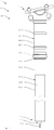
- FIGS. 2 to 5 show a bicycle component 1 according to the invention in various representations.
- the bicycle component 1 will be described below with reference to FIGS FIGS. 2 to 5 described in more detail.
- the bicycle component 1 comprises a seatpost device 2 with a first or lower support element 12 and a second or upper support element 22.
- the two support elements 12, 22 are telescopic.
- the upper support element 22 is here equipped with a saddle mount 11, via which a saddle can be mounted on the seat post 2.
- the second support member 22 may be a separate part or may be integrally formed with or fixed to the frame structure of the bicycle.
- a seal 31 and an O-ring is arranged at the opposite end of the saddle receiving 11 of the upper support member 22 at the opposite end of the saddle receiving 11 of the upper support member 22 .
- the upper support member 22 has a collar.
- a dirt deflector 21 is arranged at the saddle receiving 11 opposite end of the support member 22 at the saddle receiving 11 opposite end of the support member 22 .
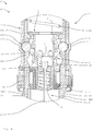
- the locking device 3 is arranged here essentially within the first support element 12.
- the locking device 3 here comprises a plurality of locking elements 4, of which only two can be seen here.
- the locking elements 4 are formed here as balls 14.
- a respective locking element 4 extends through a wall 121 of the first support element 12.
- the wall 121 has a passage opening 303.
- the locking element 4 extends further into a part of a wall 221 of the second support element 22.
- a recess 222 for the locking element 4 is incorporated.
- the wall 221 is provided with an outwardly facing projection 223.
- the recess 122 is formed here circumferentially or annular.
- a corresponding recess 202 20 is provided for each of the locking elements 4 is also possible.
- the locking elements 4 are here pressed by a piston member 5 and a cone 51 of the piston member 5 in the recess 222. In this position, the locking elements 4 prevent the second or upper support element 22 from being able to lower further. The saddle height or the position of the two support elements 12, 22 to each other is thus locked. The piston element 5 and the locking elements 4 are located in a locked or locked position. Here, the upper position 10 of the bicycle component 1 or the seat post or seat post 2 is shown. The locking elements 4 are locked in the lower recesses 222 of the second support element 22.
- the piston element 5 In order to release the locking device 3 and retract the seat post 2, the piston element 5 is pulled downwards in the direction of the longitudinal axis of the support elements 12, 22. Then, the piston member 5 is transferred to a release position. In the release position, by a corresponding pressure on the saddle, for example, with the buttocks, the saddle height can be reduced.
- the piston element 5 is conical in this case, so that it narrows towards the upper end. If the piston element 5 is moved downwards, it no longer pushes the locking elements 4 (via the cone 51) into the recess 222. Thus, the upper support element 22 can slide over the lower support element 12.
- the locking device 3 In order to lock the saddle height in the retracted, lower position 20, the locking device 3 here comprises an additional, more upwardly located recess 222. There, the locking elements 4 can be pressed by the piston member 5, so that the seat post 2 is locked in this position.
- the bicycle component 1 here comprises an energy storage device 9 designed as a spring 19, which is pretensioned when the seatpost device 2 retracts.
- the spring 19 is designed as a compression spring.
- the locking device 3 is here equipped with a pretensioning device 8.
- the tensioning device 8 here comprises a spring 18 which automatically presses the piston element 5 into the locked position.
- the piston element 5 is moved here with an actuating device 6 with a cable pulling device 7 between the release position and the locked position.
- the piston member 5 is pulled with a cable 17 of the cable pulling device 7 down.
- the piston element 5 remains in the release position and the locking elements 4 are not pressed into the recess 222. If the cable 17 is relaxed, the biasing device 8 pushes the piston unit 5 back into the locked position.
- a control panel 16 for actuating the cable pull means 7, for example, a control panel 16 as with respect to the FIG. 1 described provided.
- the cable 17 here passes through the lower support member 12 and leaves it at one end 122, which is receivable in the seat tube 104 of the bicycle 100.
- the cable 17 exits at an axial end face 123 of the support element.
- the first support element 12 is here composed of two tubular and in a connecting region 300 interconnected support portions 301, 302.
- the support sections 301, 302 are arranged overlapping in the connection region 300.
- the upper in the operative state support portion 301 has here a greater wall thickness than the lower support portion 302.
- In the upper support portion 301 Here is the passage opening 303 for the locking elements 4.
- the piston member 5 is guided in the upper support portion 301.
- the first support element 12 here has an outer contour 120, which is tuned to an inner contour 220 of the second support element.
- the outer contour 120 of the first support element 12 is provided here by the two support sections 301 and 302.
- the upper support member 22 can be slid easily over the connecting portion 300 without tilting.
- a cushion end 23 is provided in the region of the upper end of the second support element 22 in the region of the upper end of the second support element 22, a cushion end 23 is provided. At the lower end, a cushioning can be provided.
- the cable pull 17 is coupled to a cable tensioner 24.
- the user receives at any time a defined haptic feedback when touching or moving the actuator.
- the rope tightener 24 includes a biasing unit 25 and a sliding member 26 which is axially guided within the piston member. The sliding element is pressed by the biasing unit in a prestressed state and keeps the rope always taut.
- the two support elements 12, 22 have a substantially round outer contour 120 or inner contour 220.
- an anti-rotation device 400 with three guide elements 401 is provided here.
- the guide elements 401 are arranged here between the two support elements 12, 22. Thereby are the two support members 12, 22 rotatably connected to each other.
- the seatpost device 2 shown here may also include a damper device for damping the telescoping movement.
- the piston member 5 is formed as a valve piston, which influences a flow of a damper fluid.
Landscapes
- Engineering & Computer Science (AREA)
- Mechanical Engineering (AREA)
- Motorcycle And Bicycle Frame (AREA)
- Steering Devices For Bicycles And Motorcycles (AREA)
Applications Claiming Priority (1)
| Application Number | Priority Date | Filing Date | Title |
|---|---|---|---|
| DE102017118417.1A DE102017118417A1 (de) | 2017-08-11 | 2017-08-11 | Fahrradkomponente |
Publications (2)
| Publication Number | Publication Date |
|---|---|
| EP3441292A1 true EP3441292A1 (fr) | 2019-02-13 |
| EP3441292B1 EP3441292B1 (fr) | 2024-01-17 |
Family
ID=63144886
Family Applications (1)
| Application Number | Title | Priority Date | Filing Date |
|---|---|---|---|
| EP18187248.2A Active EP3441292B1 (fr) | 2017-08-11 | 2018-08-03 | Composants de bicyclette |
Country Status (3)
| Country | Link |
|---|---|
| US (1) | US10689049B2 (fr) |
| EP (1) | EP3441292B1 (fr) |
| DE (1) | DE102017118417A1 (fr) |
Cited By (2)
| Publication number | Priority date | Publication date | Assignee | Title |
|---|---|---|---|---|
| US11325668B2 (en) * | 2020-01-10 | 2022-05-10 | Hsin Lung Accessories Co., Ltd. | Adjustable shock-absorbing seat tube |
| US20240308609A1 (en) * | 2019-01-31 | 2024-09-19 | Fox Factory, Inc. | Dropper seatpost head assembly |
Families Citing this family (12)
| Publication number | Priority date | Publication date | Assignee | Title |
|---|---|---|---|---|
| CZ307998B6 (cs) * | 2018-02-05 | 2019-10-09 | KRIŠLO, Michal | Sestava pro odpružení sedla jízdního kola a sedlo jízdního kola s touto sestavou |
| US10919592B2 (en) | 2018-04-06 | 2021-02-16 | Specialized Bicycle Components, Inc. | Bicycle with compliant seat post interface |
| JP6742496B1 (ja) * | 2019-12-24 | 2020-08-19 | 有限会社藤原ホイル | サドル昇降装置 |
| US12441421B2 (en) | 2020-04-24 | 2025-10-14 | Dt Swiss Inc. | Bicycle component with an adjustable seat post device |
| DE102020111306A1 (de) | 2020-04-24 | 2021-10-28 | Dt Swiss Ag | Fahrradkomponente mit einer verstellbaren Sattelstützeinrichtung |
| EP4168297A1 (fr) * | 2020-06-23 | 2023-04-26 | Upturn Studio Spolka z Ograniczona Odpowiedzialnoscia | Cadre de bicyclette à géométrie variable et procédé de modification dynamique de la géométrie d'un cadre de bicyclette |
| TWM618794U (zh) * | 2020-10-22 | 2021-11-01 | 立盟工業有限公司 | 自行車座桿結構 |
| WO2022204158A1 (fr) * | 2021-03-26 | 2022-09-29 | The Hive Global, Inc. | Tige de selle de bicyclette télescopique à hauteur réglable et insertion de cadre fixe |
| IT202100007997A1 (it) * | 2021-03-31 | 2022-10-01 | Angelo Morelli | Reggisella telescopico |
| CN114228879B (zh) * | 2022-01-25 | 2022-12-09 | 杭州新兴车料有限公司 | 一种自行车车架用减震装置 |
| TWM636822U (zh) * | 2022-08-29 | 2023-01-21 | 巨大機械工業股份有限公司 | 伸縮機構 |
| TWI905731B (zh) * | 2023-05-04 | 2025-11-21 | 巨大機械工業股份有限公司 | 座桿、自行車及行程墊塊安裝方法 |
Citations (4)
| Publication number | Priority date | Publication date | Assignee | Title |
|---|---|---|---|---|
| DE102007063365A1 (de) * | 2007-12-29 | 2009-07-02 | Marzell Maier | Vorrichtung zur Höhenverstellung einer Sattelstütze |
| US20140061419A1 (en) * | 2012-08-30 | 2014-03-06 | Tien Hsin Industries Co., Ltd. | Multi-position adjustable height seat post |
| WO2017011848A1 (fr) * | 2015-07-21 | 2017-01-26 | Lupaan Gmbh | Dispositif de positionnement à élément télescopique et élément de support |
| ES1185933U (es) * | 2017-06-06 | 2017-06-22 | Ricard BAGÉS ESTOPÀ | Tija telescópica para bicicletas |
Family Cites Families (9)
| Publication number | Priority date | Publication date | Assignee | Title |
|---|---|---|---|---|
| CN2173745Y (zh) * | 1993-09-16 | 1994-08-10 | 舒长河 | 自行车坐垫升降减震器 |
| FR2775650A1 (fr) * | 1998-03-06 | 1999-09-10 | Alexis Defarge | Suspension de selle de velo reglable |
| US7204466B2 (en) * | 2005-03-11 | 2007-04-17 | Wu-Hong Hsieh | Quick-acting telescopic tube |
| US8079772B1 (en) * | 2006-12-21 | 2011-12-20 | Brennan James S | Multi-position bicycle seat post assembly |
| JP2014508069A (ja) * | 2011-03-11 | 2014-04-03 | スペシャライズド バイシクル コンポーネンツ インコーポレイテッド | 自転車用の調整可能組立体 |
| US9481420B2 (en) * | 2013-08-01 | 2016-11-01 | Specialized Bicycle Components, Inc. | Saddle adjustment system |
| US10562578B2 (en) * | 2015-04-15 | 2020-02-18 | Specialized Bicycle Components, Inc. | Adjustable saddle post system |
| GB2566636B (en) * | 2016-07-08 | 2021-10-13 | Schlanger Raphael | Height adjustable seatpost assembly |
| US20180134337A1 (en) * | 2016-11-16 | 2018-05-17 | Barry Lyn Holtzman | Bicycle seat post assembly |
-
2017
- 2017-08-11 DE DE102017118417.1A patent/DE102017118417A1/de not_active Withdrawn
-
2018
- 2018-08-03 EP EP18187248.2A patent/EP3441292B1/fr active Active
- 2018-08-10 US US16/100,509 patent/US10689049B2/en active Active
Patent Citations (4)
| Publication number | Priority date | Publication date | Assignee | Title |
|---|---|---|---|---|
| DE102007063365A1 (de) * | 2007-12-29 | 2009-07-02 | Marzell Maier | Vorrichtung zur Höhenverstellung einer Sattelstütze |
| US20140061419A1 (en) * | 2012-08-30 | 2014-03-06 | Tien Hsin Industries Co., Ltd. | Multi-position adjustable height seat post |
| WO2017011848A1 (fr) * | 2015-07-21 | 2017-01-26 | Lupaan Gmbh | Dispositif de positionnement à élément télescopique et élément de support |
| ES1185933U (es) * | 2017-06-06 | 2017-06-22 | Ricard BAGÉS ESTOPÀ | Tija telescópica para bicicletas |
Cited By (2)
| Publication number | Priority date | Publication date | Assignee | Title |
|---|---|---|---|---|
| US20240308609A1 (en) * | 2019-01-31 | 2024-09-19 | Fox Factory, Inc. | Dropper seatpost head assembly |
| US11325668B2 (en) * | 2020-01-10 | 2022-05-10 | Hsin Lung Accessories Co., Ltd. | Adjustable shock-absorbing seat tube |
Also Published As
| Publication number | Publication date |
|---|---|
| DE102017118417A1 (de) | 2019-02-14 |
| US10689049B2 (en) | 2020-06-23 |
| US20190047649A1 (en) | 2019-02-14 |
| EP3441292B1 (fr) | 2024-01-17 |
Similar Documents
| Publication | Publication Date | Title |
|---|---|---|
| EP3441292B1 (fr) | Composants de bicyclette | |
| EP3403910B1 (fr) | Dispositif de traction, en particulier pour une bicyclette | |
| DE102010044356B4 (de) | Höhenverstellbare Sattelstütze | |
| EP3901013B1 (fr) | Composant de bicyclette pourvu de dispositif de tige de selle réglable | |
| DE102008059894B4 (de) | Höhenverstellbare Sattelstütze | |
| DE102015101368B4 (de) | Fahrradsattelstützenanordnung | |
| DE102019006320B3 (de) | Sattellift für Fahrräder | |
| DE102017100799A1 (de) | Justierbare Fahrradsattelstützenanordnung | |
| DE102007063365A1 (de) | Vorrichtung zur Höhenverstellung einer Sattelstütze | |
| WO2017011848A1 (fr) | Dispositif de positionnement à élément télescopique et élément de support | |
| EP3325333B1 (fr) | Tige de selle télescopique pour cadre de bicyclette | |
| EP2766226A1 (fr) | Porte-charge de toit pour véhicule automobile | |
| WO2020193326A1 (fr) | Arrangement support de selle réglable | |
| DE9013266U1 (de) | Zweirad mit einem höhenverstellbaren Sattel | |
| DE19737293A1 (de) | Fahrrad | |
| EP4159602B1 (fr) | Élément de bicyclette doté d'un agencement de support de selle réglable | |
| DE102013008529B3 (de) | Sattelstütze für Fahrräder | |
| DE202007012184U1 (de) | Sattelstütze zur Höhenverstellung eines Sattels | |
| DE202012008172U1 (de) | Automatisch u. manuell während des Betriebs verstellbare Sattelstütze für Zweiradfahrzeuge | |
| EP4477520B1 (fr) | Ensemble frein hydraulique pour bicyclette entraînée au moins partiellement par la force musculaire | |
| WO2016150492A1 (fr) | Cadre de bicyclette et bicyclette correspondante | |
| DE202012101280U1 (de) | Zweirädriges Fahrzeug, ausgestattet mit einer Ausgleichsmechanik sowie Ausgleichsmechanik | |
| DE102006008992A1 (de) | Federgabel sowie ein an einem Gabelschaft fixierbares Formteil und dessen Anordnung | |
| DE202009007219U1 (de) | Auf den Untergrund wirkende Skateboardbremse | |
| DE202009004375U1 (de) | Vorrichtung zum Trainieren der Körperkräfte |
Legal Events
| Date | Code | Title | Description |
|---|---|---|---|
| PUAI | Public reference made under article 153(3) epc to a published international application that has entered the european phase |
Free format text: ORIGINAL CODE: 0009012 |
|
| STAA | Information on the status of an ep patent application or granted ep patent |
Free format text: STATUS: THE APPLICATION HAS BEEN PUBLISHED |
|
| AK | Designated contracting states |
Kind code of ref document: A1 Designated state(s): AL AT BE BG CH CY CZ DE DK EE ES FI FR GB GR HR HU IE IS IT LI LT LU LV MC MK MT NL NO PL PT RO RS SE SI SK SM TR |
|
| AX | Request for extension of the european patent |
Extension state: BA ME |
|
| STAA | Information on the status of an ep patent application or granted ep patent |
Free format text: STATUS: REQUEST FOR EXAMINATION WAS MADE |
|
| 17P | Request for examination filed |
Effective date: 20190808 |
|
| RBV | Designated contracting states (corrected) |
Designated state(s): AL AT BE BG CH CY CZ DE DK EE ES FI FR GB GR HR HU IE IS IT LI LT LU LV MC MK MT NL NO PL PT RO RS SE SI SK SM TR |
|
| STAA | Information on the status of an ep patent application or granted ep patent |
Free format text: STATUS: EXAMINATION IS IN PROGRESS |
|
| 17Q | First examination report despatched |
Effective date: 20200408 |
|
| RIC1 | Information provided on ipc code assigned before grant |
Ipc: B62J 1/08 20060101AFI20210211BHEP |
|
| P01 | Opt-out of the competence of the unified patent court (upc) registered |
Effective date: 20230517 |
|
| GRAP | Despatch of communication of intention to grant a patent |
Free format text: ORIGINAL CODE: EPIDOSNIGR1 |
|
| STAA | Information on the status of an ep patent application or granted ep patent |
Free format text: STATUS: GRANT OF PATENT IS INTENDED |
|
| INTG | Intention to grant announced |
Effective date: 20230823 |
|
| GRAS | Grant fee paid |
Free format text: ORIGINAL CODE: EPIDOSNIGR3 |
|
| GRAA | (expected) grant |
Free format text: ORIGINAL CODE: 0009210 |
|
| STAA | Information on the status of an ep patent application or granted ep patent |
Free format text: STATUS: THE PATENT HAS BEEN GRANTED |
|
| AK | Designated contracting states |
Kind code of ref document: B1 Designated state(s): AL AT BE BG CH CY CZ DE DK EE ES FI FR GB GR HR HU IE IS IT LI LT LU LV MC MK MT NL NO PL PT RO RS SE SI SK SM TR |
|
| REG | Reference to a national code |
Ref country code: GB Ref legal event code: FG4D Free format text: NOT ENGLISH |
|
| REG | Reference to a national code |
Ref country code: CH Ref legal event code: EP |
|
| REG | Reference to a national code |
Ref country code: DE Ref legal event code: R096 Ref document number: 502018013986 Country of ref document: DE |
|
| REG | Reference to a national code |
Ref country code: IE Ref legal event code: FG4D Free format text: LANGUAGE OF EP DOCUMENT: GERMAN |
|
| REG | Reference to a national code |
Ref country code: LT Ref legal event code: MG9D |
|
| REG | Reference to a national code |
Ref country code: NL Ref legal event code: MP Effective date: 20240117 |
|
| PG25 | Lapsed in a contracting state [announced via postgrant information from national office to epo] |
Ref country code: NL Free format text: LAPSE BECAUSE OF FAILURE TO SUBMIT A TRANSLATION OF THE DESCRIPTION OR TO PAY THE FEE WITHIN THE PRESCRIBED TIME-LIMIT Effective date: 20240117 |
|
| PG25 | Lapsed in a contracting state [announced via postgrant information from national office to epo] |
Ref country code: NL Free format text: LAPSE BECAUSE OF FAILURE TO SUBMIT A TRANSLATION OF THE DESCRIPTION OR TO PAY THE FEE WITHIN THE PRESCRIBED TIME-LIMIT Effective date: 20240117 |
|
| PG25 | Lapsed in a contracting state [announced via postgrant information from national office to epo] |
Ref country code: IS Free format text: LAPSE BECAUSE OF FAILURE TO SUBMIT A TRANSLATION OF THE DESCRIPTION OR TO PAY THE FEE WITHIN THE PRESCRIBED TIME-LIMIT Effective date: 20240517 |
|
| PG25 | Lapsed in a contracting state [announced via postgrant information from national office to epo] |
Ref country code: LT Free format text: LAPSE BECAUSE OF FAILURE TO SUBMIT A TRANSLATION OF THE DESCRIPTION OR TO PAY THE FEE WITHIN THE PRESCRIBED TIME-LIMIT Effective date: 20240117 |
|
| PG25 | Lapsed in a contracting state [announced via postgrant information from national office to epo] |
Ref country code: GR Free format text: LAPSE BECAUSE OF FAILURE TO SUBMIT A TRANSLATION OF THE DESCRIPTION OR TO PAY THE FEE WITHIN THE PRESCRIBED TIME-LIMIT Effective date: 20240418 |
|
| PG25 | Lapsed in a contracting state [announced via postgrant information from national office to epo] |
Ref country code: HR Free format text: LAPSE BECAUSE OF FAILURE TO SUBMIT A TRANSLATION OF THE DESCRIPTION OR TO PAY THE FEE WITHIN THE PRESCRIBED TIME-LIMIT Effective date: 20240117 Ref country code: RS Free format text: LAPSE BECAUSE OF FAILURE TO SUBMIT A TRANSLATION OF THE DESCRIPTION OR TO PAY THE FEE WITHIN THE PRESCRIBED TIME-LIMIT Effective date: 20240417 |
|
| PG25 | Lapsed in a contracting state [announced via postgrant information from national office to epo] |
Ref country code: ES Free format text: LAPSE BECAUSE OF FAILURE TO SUBMIT A TRANSLATION OF THE DESCRIPTION OR TO PAY THE FEE WITHIN THE PRESCRIBED TIME-LIMIT Effective date: 20240117 |
|
| PG25 | Lapsed in a contracting state [announced via postgrant information from national office to epo] |
Ref country code: RS Free format text: LAPSE BECAUSE OF FAILURE TO SUBMIT A TRANSLATION OF THE DESCRIPTION OR TO PAY THE FEE WITHIN THE PRESCRIBED TIME-LIMIT Effective date: 20240417 Ref country code: NO Free format text: LAPSE BECAUSE OF FAILURE TO SUBMIT A TRANSLATION OF THE DESCRIPTION OR TO PAY THE FEE WITHIN THE PRESCRIBED TIME-LIMIT Effective date: 20240417 Ref country code: LT Free format text: LAPSE BECAUSE OF FAILURE TO SUBMIT A TRANSLATION OF THE DESCRIPTION OR TO PAY THE FEE WITHIN THE PRESCRIBED TIME-LIMIT Effective date: 20240117 Ref country code: IS Free format text: LAPSE BECAUSE OF FAILURE TO SUBMIT A TRANSLATION OF THE DESCRIPTION OR TO PAY THE FEE WITHIN THE PRESCRIBED TIME-LIMIT Effective date: 20240517 Ref country code: HR Free format text: LAPSE BECAUSE OF FAILURE TO SUBMIT A TRANSLATION OF THE DESCRIPTION OR TO PAY THE FEE WITHIN THE PRESCRIBED TIME-LIMIT Effective date: 20240117 Ref country code: GR Free format text: LAPSE BECAUSE OF FAILURE TO SUBMIT A TRANSLATION OF THE DESCRIPTION OR TO PAY THE FEE WITHIN THE PRESCRIBED TIME-LIMIT Effective date: 20240418 Ref country code: FI Free format text: LAPSE BECAUSE OF FAILURE TO SUBMIT A TRANSLATION OF THE DESCRIPTION OR TO PAY THE FEE WITHIN THE PRESCRIBED TIME-LIMIT Effective date: 20240117 Ref country code: ES Free format text: LAPSE BECAUSE OF FAILURE TO SUBMIT A TRANSLATION OF THE DESCRIPTION OR TO PAY THE FEE WITHIN THE PRESCRIBED TIME-LIMIT Effective date: 20240117 Ref country code: BG Free format text: LAPSE BECAUSE OF FAILURE TO SUBMIT A TRANSLATION OF THE DESCRIPTION OR TO PAY THE FEE WITHIN THE PRESCRIBED TIME-LIMIT Effective date: 20240117 |
|
| PG25 | Lapsed in a contracting state [announced via postgrant information from national office to epo] |
Ref country code: PL Free format text: LAPSE BECAUSE OF FAILURE TO SUBMIT A TRANSLATION OF THE DESCRIPTION OR TO PAY THE FEE WITHIN THE PRESCRIBED TIME-LIMIT Effective date: 20240117 Ref country code: PT Free format text: LAPSE BECAUSE OF FAILURE TO SUBMIT A TRANSLATION OF THE DESCRIPTION OR TO PAY THE FEE WITHIN THE PRESCRIBED TIME-LIMIT Effective date: 20240517 |
|
| PG25 | Lapsed in a contracting state [announced via postgrant information from national office to epo] |
Ref country code: SE Free format text: LAPSE BECAUSE OF FAILURE TO SUBMIT A TRANSLATION OF THE DESCRIPTION OR TO PAY THE FEE WITHIN THE PRESCRIBED TIME-LIMIT Effective date: 20240117 Ref country code: PT Free format text: LAPSE BECAUSE OF FAILURE TO SUBMIT A TRANSLATION OF THE DESCRIPTION OR TO PAY THE FEE WITHIN THE PRESCRIBED TIME-LIMIT Effective date: 20240517 Ref country code: PL Free format text: LAPSE BECAUSE OF FAILURE TO SUBMIT A TRANSLATION OF THE DESCRIPTION OR TO PAY THE FEE WITHIN THE PRESCRIBED TIME-LIMIT Effective date: 20240117 Ref country code: LV Free format text: LAPSE BECAUSE OF FAILURE TO SUBMIT A TRANSLATION OF THE DESCRIPTION OR TO PAY THE FEE WITHIN THE PRESCRIBED TIME-LIMIT Effective date: 20240117 |
|
| PG25 | Lapsed in a contracting state [announced via postgrant information from national office to epo] |
Ref country code: DK Free format text: LAPSE BECAUSE OF FAILURE TO SUBMIT A TRANSLATION OF THE DESCRIPTION OR TO PAY THE FEE WITHIN THE PRESCRIBED TIME-LIMIT Effective date: 20240117 |
|
| PG25 | Lapsed in a contracting state [announced via postgrant information from national office to epo] |
Ref country code: SM Free format text: LAPSE BECAUSE OF FAILURE TO SUBMIT A TRANSLATION OF THE DESCRIPTION OR TO PAY THE FEE WITHIN THE PRESCRIBED TIME-LIMIT Effective date: 20240117 |
|
| REG | Reference to a national code |
Ref country code: DE Ref legal event code: R097 Ref document number: 502018013986 Country of ref document: DE |
|
| PG25 | Lapsed in a contracting state [announced via postgrant information from national office to epo] |
Ref country code: EE Free format text: LAPSE BECAUSE OF FAILURE TO SUBMIT A TRANSLATION OF THE DESCRIPTION OR TO PAY THE FEE WITHIN THE PRESCRIBED TIME-LIMIT Effective date: 20240117 Ref country code: CZ Free format text: LAPSE BECAUSE OF FAILURE TO SUBMIT A TRANSLATION OF THE DESCRIPTION OR TO PAY THE FEE WITHIN THE PRESCRIBED TIME-LIMIT Effective date: 20240117 |
|
| PG25 | Lapsed in a contracting state [announced via postgrant information from national office to epo] |
Ref country code: SK Free format text: LAPSE BECAUSE OF FAILURE TO SUBMIT A TRANSLATION OF THE DESCRIPTION OR TO PAY THE FEE WITHIN THE PRESCRIBED TIME-LIMIT Effective date: 20240117 |
|
| PG25 | Lapsed in a contracting state [announced via postgrant information from national office to epo] |
Ref country code: SM Free format text: LAPSE BECAUSE OF FAILURE TO SUBMIT A TRANSLATION OF THE DESCRIPTION OR TO PAY THE FEE WITHIN THE PRESCRIBED TIME-LIMIT Effective date: 20240117 Ref country code: SK Free format text: LAPSE BECAUSE OF FAILURE TO SUBMIT A TRANSLATION OF THE DESCRIPTION OR TO PAY THE FEE WITHIN THE PRESCRIBED TIME-LIMIT Effective date: 20240117 Ref country code: RO Free format text: LAPSE BECAUSE OF FAILURE TO SUBMIT A TRANSLATION OF THE DESCRIPTION OR TO PAY THE FEE WITHIN THE PRESCRIBED TIME-LIMIT Effective date: 20240117 Ref country code: EE Free format text: LAPSE BECAUSE OF FAILURE TO SUBMIT A TRANSLATION OF THE DESCRIPTION OR TO PAY THE FEE WITHIN THE PRESCRIBED TIME-LIMIT Effective date: 20240117 Ref country code: DK Free format text: LAPSE BECAUSE OF FAILURE TO SUBMIT A TRANSLATION OF THE DESCRIPTION OR TO PAY THE FEE WITHIN THE PRESCRIBED TIME-LIMIT Effective date: 20240117 Ref country code: CZ Free format text: LAPSE BECAUSE OF FAILURE TO SUBMIT A TRANSLATION OF THE DESCRIPTION OR TO PAY THE FEE WITHIN THE PRESCRIBED TIME-LIMIT Effective date: 20240117 |
|
| PLBE | No opposition filed within time limit |
Free format text: ORIGINAL CODE: 0009261 |
|
| STAA | Information on the status of an ep patent application or granted ep patent |
Free format text: STATUS: NO OPPOSITION FILED WITHIN TIME LIMIT |
|
| PG25 | Lapsed in a contracting state [announced via postgrant information from national office to epo] |
Ref country code: IT Free format text: LAPSE BECAUSE OF FAILURE TO SUBMIT A TRANSLATION OF THE DESCRIPTION OR TO PAY THE FEE WITHIN THE PRESCRIBED TIME-LIMIT Effective date: 20240117 |
|
| 26N | No opposition filed |
Effective date: 20241018 |
|
| PG25 | Lapsed in a contracting state [announced via postgrant information from national office to epo] |
Ref country code: IT Free format text: LAPSE BECAUSE OF FAILURE TO SUBMIT A TRANSLATION OF THE DESCRIPTION OR TO PAY THE FEE WITHIN THE PRESCRIBED TIME-LIMIT Effective date: 20240117 |
|
| REG | Reference to a national code |
Ref country code: CH Ref legal event code: PL |
|
| PG25 | Lapsed in a contracting state [announced via postgrant information from national office to epo] |
Ref country code: LU Free format text: LAPSE BECAUSE OF NON-PAYMENT OF DUE FEES Effective date: 20240803 |
|
| GBPC | Gb: european patent ceased through non-payment of renewal fee |
Effective date: 20240803 |
|
| PG25 | Lapsed in a contracting state [announced via postgrant information from national office to epo] |
Ref country code: SI Free format text: LAPSE BECAUSE OF FAILURE TO SUBMIT A TRANSLATION OF THE DESCRIPTION OR TO PAY THE FEE WITHIN THE PRESCRIBED TIME-LIMIT Effective date: 20240117 Ref country code: MC Free format text: LAPSE BECAUSE OF FAILURE TO SUBMIT A TRANSLATION OF THE DESCRIPTION OR TO PAY THE FEE WITHIN THE PRESCRIBED TIME-LIMIT Effective date: 20240117 Ref country code: CH Free format text: LAPSE BECAUSE OF NON-PAYMENT OF DUE FEES Effective date: 20240831 |
|
| REG | Reference to a national code |
Ref country code: BE Ref legal event code: MM Effective date: 20240831 |
|
| PG25 | Lapsed in a contracting state [announced via postgrant information from national office to epo] |
Ref country code: GB Free format text: LAPSE BECAUSE OF NON-PAYMENT OF DUE FEES Effective date: 20240803 |
|
| PG25 | Lapsed in a contracting state [announced via postgrant information from national office to epo] |
Ref country code: BE Free format text: LAPSE BECAUSE OF NON-PAYMENT OF DUE FEES Effective date: 20240831 |
|
| PG25 | Lapsed in a contracting state [announced via postgrant information from national office to epo] |
Ref country code: FR Free format text: LAPSE BECAUSE OF NON-PAYMENT OF DUE FEES Effective date: 20240831 |
|
| PG25 | Lapsed in a contracting state [announced via postgrant information from national office to epo] |
Ref country code: IE Free format text: LAPSE BECAUSE OF NON-PAYMENT OF DUE FEES Effective date: 20240803 |
|
| PGFP | Annual fee paid to national office [announced via postgrant information from national office to epo] |
Ref country code: DE Payment date: 20250919 Year of fee payment: 8 |
|
| REG | Reference to a national code |
Ref country code: AT Ref legal event code: MM01 Ref document number: 1650383 Country of ref document: AT Kind code of ref document: T Effective date: 20240803 |
|
| PG25 | Lapsed in a contracting state [announced via postgrant information from national office to epo] |
Ref country code: AT Free format text: LAPSE BECAUSE OF NON-PAYMENT OF DUE FEES Effective date: 20240803 |
|
| PG25 | Lapsed in a contracting state [announced via postgrant information from national office to epo] |
Ref country code: CY Free format text: LAPSE BECAUSE OF FAILURE TO SUBMIT A TRANSLATION OF THE DESCRIPTION OR TO PAY THE FEE WITHIN THE PRESCRIBED TIME-LIMIT; INVALID AB INITIO Effective date: 20180803 |
|
| PG25 | Lapsed in a contracting state [announced via postgrant information from national office to epo] |
Ref country code: HU Free format text: LAPSE BECAUSE OF FAILURE TO SUBMIT A TRANSLATION OF THE DESCRIPTION OR TO PAY THE FEE WITHIN THE PRESCRIBED TIME-LIMIT; INVALID AB INITIO Effective date: 20180803 |