EP3441292B1 - Bicycle component - Google Patents
Bicycle component Download PDFInfo
- Publication number
- EP3441292B1 EP3441292B1 EP18187248.2A EP18187248A EP3441292B1 EP 3441292 B1 EP3441292 B1 EP 3441292B1 EP 18187248 A EP18187248 A EP 18187248A EP 3441292 B1 EP3441292 B1 EP 3441292B1
- Authority
- EP
- European Patent Office
- Prior art keywords
- support member
- support
- bicycle component
- support element
- bicycle
- Prior art date
- Legal status (The legal status is an assumption and is not a legal conclusion. Google has not performed a legal analysis and makes no representation as to the accuracy of the status listed.)
- Active
Links
Images
Classifications
-
- B—PERFORMING OPERATIONS; TRANSPORTING
- B62—LAND VEHICLES FOR TRAVELLING OTHERWISE THAN ON RAILS
- B62J—CYCLE SADDLES OR SEATS; AUXILIARY DEVICES OR ACCESSORIES SPECIALLY ADAPTED TO CYCLES AND NOT OTHERWISE PROVIDED FOR, e.g. ARTICLE CARRIERS OR CYCLE PROTECTORS
- B62J1/00—Saddles or other seats for cycles; Arrangement thereof; Component parts
- B62J1/08—Frames for saddles; Connections between saddle frames and seat pillars; Seat pillars
-
- B—PERFORMING OPERATIONS; TRANSPORTING
- B62—LAND VEHICLES FOR TRAVELLING OTHERWISE THAN ON RAILS
- B62J—CYCLE SADDLES OR SEATS; AUXILIARY DEVICES OR ACCESSORIES SPECIALLY ADAPTED TO CYCLES AND NOT OTHERWISE PROVIDED FOR, e.g. ARTICLE CARRIERS OR CYCLE PROTECTORS
- B62J1/00—Saddles or other seats for cycles; Arrangement thereof; Component parts
- B62J1/02—Saddles resiliently mounted on the frame; Equipment therefor, e.g. springs
- B62J1/06—Saddles capable of parallel motion up and down
-
- B—PERFORMING OPERATIONS; TRANSPORTING
- B62—LAND VEHICLES FOR TRAVELLING OTHERWISE THAN ON RAILS
- B62K—CYCLES; CYCLE FRAMES; CYCLE STEERING DEVICES; RIDER-OPERATED TERMINAL CONTROLS SPECIALLY ADAPTED FOR CYCLES; CYCLE AXLE SUSPENSIONS; CYCLE SIDECARS, FORECARS, OR THE LIKE
- B62K19/00—Cycle frames
- B62K19/30—Frame parts shaped to receive other cycle parts or accessories
- B62K19/36—Frame parts shaped to receive other cycle parts or accessories for attaching saddle pillars, e.g. adjustable during ride
-
- B—PERFORMING OPERATIONS; TRANSPORTING
- B62—LAND VEHICLES FOR TRAVELLING OTHERWISE THAN ON RAILS
- B62J—CYCLE SADDLES OR SEATS; AUXILIARY DEVICES OR ACCESSORIES SPECIALLY ADAPTED TO CYCLES AND NOT OTHERWISE PROVIDED FOR, e.g. ARTICLE CARRIERS OR CYCLE PROTECTORS
- B62J1/00—Saddles or other seats for cycles; Arrangement thereof; Component parts
- B62J1/08—Frames for saddles; Connections between saddle frames and seat pillars; Seat pillars
- B62J2001/085—Seat pillars having mechanisms to vary seat height, independently of the cycle frame
Definitions
- the present invention relates to a bicycle component for a bicycle that is at least partially powered by muscle power and has a seat support device that can be adjusted telescopically between at least two positions for adjusting a saddle height.
- the saddle when driving downhill, the saddle must be appropriately low so that the rider can put his weight behind the saddle in order to shift the center of gravity backwards.
- the saddle height When riding in the sitting position, the saddle height must be adjusted ergonomically to enable a favorable input of force into the drive.
- adjustable seat posts which are also known as telescopic supports.
- two telescoping tubes are used, with the thicker tube being inserted into the bottom of the frame and the thinner tube protruding upwards from the thicker tube.
- This can make a very A large adjustment range can be provided, as the inner tube can be immersed in the bicycle frame to almost any depth.
- the driver can usually operate the seat post adjustment mechanism from the handlebars. This means the saddle height can be adjusted while driving without the rider having to get off.
- a generic bicycle component with such a seat post is from the US 2014/061419 A1 known.
- Hydraulic seat supports allow adjustment to a wide variety of height positions.
- One disadvantage, however, is that they are difficult to dismantle, clean and maintain. Special tools are required for dismantling.
- hydraulic fluid can leak if disassembly is not carried out properly.
- the well-known adjustable seat posts generally work satisfactorily, but also offer potential for improvement.
- the known solutions can be optimized in terms of their practical suitability and their weight as well as their manufacturing costs and in particular the maintenance effort.
- an adjustable seat post is to be provided which is reliable and functions in an uncomplicated manner and is economical to produce and, in particular, is easy to maintain.
- the bicycle component according to the invention is intended for a bicycle that is at least partially powered by muscle power.
- the bicycle component comprises a seat support device that is telescopically adjustable between at least two positions for adjusting a saddle height.
- the bicycle component comprises at least one locking device for locking the seat support device in at least one of the positions.
- the seat support device comprises at least two support elements that are movable relative to one another, namely a first support element and at least one second support element.
- the first support element is on a frame structure of the bicycle; can be firmly attached.
- the second support element is used to hold a saddle.
- the first support element is arranged at least in sections within the second support element.
- the second support element can be moved at least in sections over the first support element.
- Such an “upside-down” design enables a very simple structure.
- the second support element is designed to be single-walled.
- the locking device is at least partially arranged within the first support element and comprises at least one locking element which, in the locked state, extends through at least one wall of the first support element into the second support element.
- the second support element slides on the first support element during a height adjustment (of a saddle) and/or is guided through the first support element.
- the bicycle component according to the invention offers many advantages.
- the arrangement of the two support elements according to the invention offers a significant advantage.
- This allows the second or upper support element can be designed structurally independently of the frame structure and in particular of the seat tube diameter. This results in significantly higher degrees of freedom for the design and significantly more flexible design options in order to obtain a reliable and cost-optimized seat support device.
- the bicycle component according to the invention can therefore also be used particularly well in other types of ferry bikes than mountain bikes, e.g. B. on racing bikes, cyclo-cross bikes and trekking bikes and e-bikes.
- the bicycle component according to the invention therefore also enables an advantageous weight reduction, which is particularly advantageous for sports bikes.
- Another advantage is that there are higher degrees of freedom for mounting the saddle on the second support element.
- the upper part of telescopic seat posts could only be designed within very narrow limits, as it had to have a particularly small diameter in order to fit into the lower part when the saddle was retracted.
- the lower part could't simply be enlarged because it has to fit into the seat tube of the frame.
- the first support element consists of a light material. It is possible for the first and/or the second support element to consist at least partially or completely of a fiber-reinforced material such as a carbon material. Particularly preferably, the first support element consists at least partially and in particular at least to a significant extent or essentially completely or completely (at least) one fiber composite material.
- the wall thickness of the first support element can be designed independently of the dimensions of the upper support element.
- the first or lower support element can be designed with an optimal lightweight construction.
- the lower part of telescopic seat posts had to be made so thin-walled that the upper part could be immersed in order to make telescoping possible.
- the lower support element can z. b. be made so large that it can be inserted precisely into the seat tube. This results in an overall considerably stiffer and more resilient and at the same time weight-optimized seat support device.
- the inventive arrangement of the two support elements means that the seat support device is considerably less sensitive to contamination and therefore offers a particularly reliable function. Because the upper support element can be moved over the lower support element, dirt can be wiped off much more easily and simply fall down. In particular, dirt and moisture do not collect directly at the top of the connection point between the two support elements, but are wiped off downwards.
- the term telescoping is understood to mean, in particular, a relative telescoping of the support elements.
- the second support element in particular can be pushed over the first support element at least in sections.
- the second support element moves upwards at least in sections on the first support element.
- the first support element telescopes into the second support element or the second support element moves on the first support element.
- the bicycle component can be designed as a seat post.
- Tubular support elements are preferably provided.
- the support elements are at least partially hollow.
- the second support element is arranged in particular at the top and the first support element is arranged in particular at the bottom.
- the first support element is in particular accommodated at least in sections in a seat tube of a frame structure of a bicycle.
- the frame structure can be part of the bicycle component.
- the bicycle component can also include a bicycle or be designed as such.
- At least one outer contour of the first support element and at least one inner contour of the second support element are designed to fit one another at least in sections, so that the second support element is guided along the first support element.
- the outer contour and the inner contour are designed to fit one another exactly where the two support elements slide or telescope along one another.
- the first support element is guided in the second support element or the second support element is on the outside of the first Support element guided.
- the first support element can be an integral part of the frame structure of the bicycle or the bicycle frame and can be firmly connected to it or made in one piece with it.
- At least one anti-rotation device is arranged between the two support elements. This prevents the saddle from twisting during operation and also when lowering or extending the seat support device.
- the anti-twist protection is provided in particular by the outer contour of the first support element and the inner contour of the second support element.
- the anti-rotation device can also include at least one linear guide with at least one guide rail.
- the guide rail is, for example, embedded in a recess in the first or second support element.
- the anti-rotation device can also have at least one toothing.
- a differently designed anti-twist device is also possible.
- the anti-twist device enables smooth adjustment.
- the anti-twist device is designed to be essentially free of play or (practically) free of play.
- the support elements are cylindrical.
- an outer diameter of the first support element is smaller than an inner diameter of the second support element.
- the support elements can also be designed to be out of round at least in sections.
- the locking device is preferably arranged at least partially within one of the support elements and in particular within the first support element. This offers a particularly compact seat support device and low-maintenance accommodation.
- the first Support element arranged at least one receiving space in which the locking device is at least partially arranged.
- the locking device is arranged in the first support element to such an extent that only the at least one locking element is not arranged inside the first support element or outside of the first support element.
- the locking device can also be arranged at least partially in the second support element.
- the locking device preferably comprises at least one locking element.
- the locking element In the locked state, the locking element extends in particular through at least one wall of the first support element into the second support element. This offers a structurally simple and at the same time very reliable locking and enables play-free implementation.
- the locking element In particular, in the locked state, the locking element extends into at least one wall of the second support element.
- the first support element can comprise at least one through opening. For example, at least one hole is arranged in the wall.
- a plurality of locking elements is provided.
- the locking device is particularly suitable and designed to positively block relative mobility of the support elements to one another by means of the locking element.
- the locking element In the locked state, the locking element extends in particular only into part of a wall of the second support element.
- the second support element comprises at least one recess in the wall in which the locking element is arranged in the locked state.
- the Recess is designed, for example, as a depression or depression. However, it is also possible for the locking element to pass through the wall of the second support element in the locked state.
- the locking device is particularly suitable and designed to at least partially press the locking element into at least one recess in the second support element by means of at least one piston element. This ensures reliable positioning of the locking elements.
- a locked position exists when the piston element presses the locking element into the second support element.
- the piston element presses the locking element into the recess of the second support element.
- the locking device comprises at least one piston element. The recess is arranged in particular in the wall of the second support element.
- the piston element is movable in particular in the direction of a longitudinal axis of the support elements.
- the piston element presses the locking element transversely to the longitudinal axis of the support element.
- the piston element comprises at least one wedge surface with which a longitudinal movement of the piston element can be converted into a transverse movement of the locking element.
- the piston element is rod-shaped and/or cylindrical.
- the wedge surface is preferably formed on a cone and is designed in a conical shape. It is also possible for the piston element to be annular and/or designed as a bushing.
- the wedge element is adapted to an inner diameter and/or an inner contour of the first support element.
- the piston element is guided in the first support element and is preferably linear guided.
- the locking element or the locking elements is or are preferably inserted loosely and are in particular not guided.
- the piston element is preferably movable into at least one release position in the direction of a longitudinal axis of the first support element.
- the piston element does not press the locking element into the second support element in the release position.
- the piston element has at least one recess in which the locking element can be received in the release position.
- the locking element is no longer arranged in (the wall of) the second support element in the release position.
- the bicycle component in particular comprises at least one actuating device for releasing and/or activating the locking mechanism.
- the actuating device is particularly suitable and designed to move the piston element into the release position and/or into the locked position.
- the actuating device can be at least partially manually or completely manually operable. Motor-assisted and/or fully automatic operation and/or wireless operation and functionality are also possible. In preferred embodiments, a mechanical solution is implemented, although it is reserved to implement electrical and/or remote-controlled and/or wireless control options if these are technically possible and legally permissible.
- the piston element for assuming the release position in the direction of an end of the first support element facing away from the second support element or one in the Frame structure removable end of the first support element movable.
- the piston element can be moved to assume the release position in the direction of an end of the first support element facing away from the second support element by pulling and preferably by at least one cable pull device.
- the wedge element can be moved in particular in the direction of that end of the first support element which is opposite the end of the first support element connected to the second support element.
- the wedge element can in particular be moved from the locked position into the release position by moving it to the end of the first support element, which can be received in the frame structure.
- the piston element is particularly preferably suitable and designed to be pulled into the release position by means of at least one actuating device. Such pulling can be implemented particularly inexpensively and robustly.
- the piston element is pulled with the actuating device to an end of the first support element, which can be received in the frame structure or which faces away from the second support element. It is also possible for the piston element to be pressed into the release position by means of the actuating device.
- the bicycle component comprises at least one actuation device for releasing and/or activating the locking device.
- the actuating device is in particular the actuating device described above, by means of which the piston element is pulled into the release position.
- the actuating device is preferably at least partially mechanical.
- the actuation device can be complete be mechanically designed.
- the actuating device comprises at least one cable pull device with at least one cable pull.
- the actuating device can comprise at least one mechanical operating lever with which the cable pull can be moved into at least one position or at least one of the two positions (released/locked).
- a cable pull device offers many advantages and is, for example, particularly low-maintenance and operationally reliable.
- the actuating device is suitable and designed to pull the piston element by means of the cable pull device.
- the cable runs in particular within the first support element.
- the cable also runs within the frame structure and in particular a seat tube of the bicycle.
- the cable pull is not positioned or held in a precisely defined manner in positions when the piston element is not locked.
- the actuating device can then be moved smoothly in at least one direction without the user receiving haptic feedback. It may then appear to the user that the seat support device is not operating in a defined manner and the user's confidence in its reliability may be compromised.
- the cable pull can be coupled with a cable tensioner in order to provide defined haptic feedback for the user at all times.
- the rope tensioner prevents play that might otherwise occur.
- the cable pull is preferably coupled in particular to the piston element via at least one cable tensioner.
- the rope tensioner preferably comprises at least one Pre-tensioning unit that leads to a tightening of the rope.
- the biasing unit can be designed as a mechanical spring, but can also be designed, for example, on a magnetic basis.
- the pretensioning unit is preferably arranged on a sliding element on which the or one end of the cable is held. The sliding element is pressed into a prestressed state via the prestressing unit.
- a pretensioning force of the pretensioning unit is opposite to a pretensioning of the pretensioning device.
- the level of the prestressing force of the prestressing unit is preferably significantly lower than a level of the prestressing force of the prestressing device, so that an effective force of the prestressing device always acts.
- the prestressing force of the prestressing unit is less than half as large and is in particular less than a quarter or eighth of the prestressing force of the prestressing device.
- the pretensioning unit ensures that a force for tensioning the cable is applied in every state of the actuating device or in every position of the (mechanical) operating lever.
- the user receives feedback of a precisely defined functionality at any time.
- the actuating device is at least partially designed to be hydraulic.
- the actuating device preferably comprises at least one control part for pulling or tensioning the cable.
- the control panel can be mounted in particular on a driver's handlebar device.
- the operating part is in particular also designed for actuating and/or tensioning and/or relaxing the cable pull.
- the operating part can be suitable and designed to fix the cable pull, for example in the release position and/or the locked position.
- the pulley can be in one of the two positions e.g. B. be preloaded by a spring.
- the cable exits from an axial end face of the first support element.
- This enables the cable to be laid in a well-protected and easy-to-assemble manner, for example within the frame structure of the bicycle.
- the cable exits at one end of the first support element, which can be accommodated in the frame structure or is facing away from the second support element.
- the cable exits at one end of the first support element, which in an operational position is directed downwards or towards the ground.
- the cable pull device is suitable and designed so that the cable pull can be laid within a frame structure of a bicycle and in particular at least within a seat tube. It is also possible for the cable pull to exit on a radial side of the first support element.
- the bicycle component in particular comprises at least one preloading device or a preloading device, which can be preloaded by pulling the piston element into the release position.
- the pretensioning device is particularly suitable and designed to move the piston element from the release position into the locked position when the cable pull is relaxed. This offers a cost-effective and reliable reset of the locking device. This can reliably ensure that the saddle remains in the desired position after adjustment.
- the pretensioning device includes in particular at least one energy accumulator and, for example, at least one spring and/or gas spring.
- the piston element is in the counter-tensioning force of the pretensioning device Release position movable.
- the actuating device is suitable and designed to automatically return the piston element to the locked position by means of the pretensioning device when there is no longer any tensile stress on the piston element or when the cable is no longer pulled.
- the biasing device is particularly suitable and designed to move the piston element from the release position into the locked position when the piston element is no longer actively held in the release position.
- the locking element comprises at least one ball or is designed as at least one. With such a ball, it can be achieved particularly inexpensively and without additional springs or the like that the locking is released when the piston element is pulled into the release position.
- a plurality of locking elements and in particular balls are particularly preferably provided. For example, two or three or four or more locking elements are provided.
- the locking element can also include at least one pin and/or at least one pawl or the like. Other suitable configurations of the locking element are also possible. It is possible for the locking element to be assigned at least one biasing device, which moves the locking element out of the second support element when the wedge element is in the release position.
- At least one energy storage device is preferably arranged within the second support element.
- the bicycle component comprises at least one energy storage device.
- the energy storage device is particularly suitable and designed by a Retracting the first support element into the second support element to be at least partially charged.
- the energy storage device is particularly suitable and designed to be at least partially unloaded by extending the first support element from the second support element, so that the seat support device can be extended at least partially automatically.
- Such a power storage device enables the seat support device to be reset very comfortably. For example, you only need to lift your buttocks and operate the control panel.
- the energy storage device can be charged in particular by the driver's weight.
- the energy storage device is supported in particular on the first and second support elements.
- the direction of force of the force storage device runs in particular in the direction of a longitudinal axis of the support elements. It is possible for a force for moving the saddle of the force storage device to be adjustable.
- the energy storage device in particular comprises at least one spring and/or at least one gas spring. In particular, the energy storage device also resets the cable pull and/or tensions it.
- the force storage device is designed such that an extension speed of the seat support device does not exceed a predetermined maximum speed.
- at least one spring and/or gas spring with a defined spring force is used for this purpose.
- Such a configuration has the advantage that excessive speed or even jerky extension of the second support element is reliably avoided. So can e.g. B. there is no need for a complex and weight-increasing damper device. However, the use of a damper device is possible. In In simple configurations, a friction element can be used with a longer stroke.
- At least one friction element is preferably arranged between the two support elements.
- the friction element preferably comprises at least one seal and in particular at least one sealing ring and/or at least one O-ring or the like.
- Such a friction element has the advantage that the speed can be slowed down when the seat support device is extended.
- Such final damping can act in particular as a function of the stroke and, for example, act on the last 10 mm or in particular 5 mm or 2 mm of the stroke.
- the first support element preferably comprises at least two tubular support sections that are firmly connected to one another in a connection area.
- the two support sections are preferably glued together.
- the two support sections can also be pressed and/or welded together.
- Other suitable non-positive and/or positive and/or material connection types are also possible.
- the use of light materials such as light metal is preferred. Fiber-reinforced plastics such as carbon materials are particularly preferred.
- connection area There is preferably at least one in the connection area
- Outer contour of the first support element is formed to fit precisely to at least one inner contour of the second support element. This has the advantage that smooth guidance is also achieved in the connection area.
- the outer contour and the inner contour are in particular designed such that the second support element is guided on the first support element.
- the support sections are arranged to overlap at least in the connection area.
- a coaxial arrangement of the two support sections is provided in the connection area. It is also possible to arrange the support sections in abutting manner.
- one support section has, at least in sections, a greater wall thickness than the other support section.
- the one support section has at least one through opening for the locking element.
- the other support section does not have a through opening for the locking element.
- the one support section consists at least to a significant extent of a fiber composite material.
- the other support section consists at least to a significant extent of a metallic lightweight construction material.
- the lightweight material is in particular an aluminum material and, for example, an aluminum alloy. Through such a mixture of materials, an optimal weight with a particularly high level of stability is achieved for each support section and its respective task. Lightweight construction materials containing magnesium or other metallic lightweight construction materials are also possible.
- both support sections can be made at least to a significant extent from a metallic lightweight material. This offers a particularly cost-optimized and at the same time very reliable seat post. Both support sections can also be made at least to a significant extent from a fiber composite material.
- the first support element can also be provided by a single or continuous tubular component.
- a single or continuous tubular component offers the advantages of the bicycle component according to the invention together with a special cost optimization.
- the component is made in particular from a fiber composite material or from a metallic lightweight material.
- first support element low metal, fiber composite material, carbon
- second support element By selecting suitable and light materials for the first support element (light metal, fiber composite material, carbon) and the second support element, a low overall weight with high stability can be achieved. If the locking elements and individual components wear out, they can easily be replaced.
- the locking elements preferably consist of a resilient material and in particular of a more resilient and wear-resistant material than the first and/or the second support element. This can save maintenance effort.
- the locking elements can be hardened and / or have at least one coating to protect the surface, for example. B. to harden.
- the piston element is guided in at least one support section, preferably in the support section with the greater wall thickness.
- the prestressing device is preferably accommodated in the support section with the greater wall thickness.
- the one support section provides a linear guide for the piston element. It is also preferred that the energy storage device is supported directly or indirectly on the one support section.
- a stroke of the seat support device is between 15 mm and 60 mm and in particular between 20 mm and 50 mm.
- the maximum stroke can also be 40mm or 30mm.
- a stroke between 30 mm and 50 mm is particularly preferably provided.
- a shorter or longer maximum stroke is also possible.
- a stroke of up to 80 mm or up to 100 mm is also conceivable and preferred.
- the stroke refers in particular to a movement of the second support element relative to the first support element.
- Such a design has proven to be particularly advantageous for adapting the seating position with regard to the aerodynamic properties of a bicycle, including the rider on it.
- a one millimeter reduction in seat height can reduce the power required to drive by up to 1W, or even more at high driving speeds, due to reduced wind resistance. Therefore, in many riding situations and especially in competitions or with e-bikes to improve the range, it is a great advantage to lower the saddle height. However, only a slight lowering should occur so that the ergonomically favorable sitting position is maintained.
- the bicycle component according to the invention is particularly suitable for this. The one before The maximum stroke described therefore enables a significant improvement in the aerodynamic properties and thus the driving performance of the driver or the e-bike drive.
- Security is increased.
- the user of an e-bike can lower the seat support device at a traffic light or when stopping in order to be able to support himself better and more safely with his foot.
- the seat support device can only be adjusted between two positions.
- the positions are in particular end positions. In particular, no intermediate positions are provided. This offers quick and comfortable adjustment of a seating position for reduced wind resistance.
- the invention provides a very simple and reliable option for height adjustment.
- At least one passage opening is arranged in the first support element and at least one recess is arranged in the second support element for each intended position. In particular, both positions can be locked.
- At least one intermediate position can be set between the two positions.
- the locking device is suitable and designed to automatically transition back into a locked position and lock the position when one of the two positions and/or an intermediate position is reached. This may require actuation and/or release of the actuation device.
- the bicycle component comprises at least one hydraulic damper device for damping the telescoping movement.
- extending the Seat support device can be dampened.
- Retraction can also be dampened. This offers particularly comfortable adjustment of the seat support device, as jerky extension is avoided when the lock is released.
- the damper device preferably comprises at least two damper chambers, between which a damper fluid can flow via at least one valve device.
- the valve device can be used to specifically influence a flow of the damper fluid between the damper chambers.
- the damping can be fixed or adjustable.
- the piston element preferably provides at least part of the valve device of the damper device.
- the piston element is designed as a valve piston of the valve device.
- the piston element is suitable and designed to specifically influence the flow of the damper fluid between the damper chambers.
- the damper device and the energy storage device can be combined with one another.
- the damper device can be combined with at least one spring.
- the force storage device and the damper device are designed as a gas pressure shock absorber.
- the bicycle according to the invention can be operated at least partially with muscle power and includes at least one bicycle component as described above.
- the bicycle according to the invention also offers many advantages.
- One advantage is that the bike always offers an optimal seating position, even in different riding situations.
- the cable runs at least in sections within a seat tube and/or another frame structure of the bicycle.
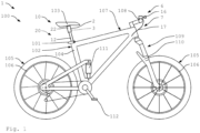
- the Figure 1 shows a bicycle 100 designed as a mountain bike with a bicycle component 1 according to the invention.
- the bicycle 100 can also be designed as a partially muscle-powered two-wheeler and, for example, as an e-bike.
- the bicycle 100 has two wheels 105, each of which is equipped with a hub and a rim 106.
- the bike 100 has full suspension.
- the fork is 109 designed as a suspension fork 110 and the frame 107 has a rear wheel damper 111.
- the bicycle 100 includes a saddle 103, a frame 107, a handlebar 108 and other bicycle components.
- the bicycle 100 here includes a derailleur gear 113.
- the bicycle 100 also has a braking device, not shown in detail.
- the bicycle component 1 includes an adjustable seat support device 2, which is accommodated here in a frame structure 102 designed as a seat tube 104.
- the seat support device 2 is fastened in the seat tube 104 by means of a seat tube clamp 101.
- the seat support device 2 is designed to be adjustable so that the saddle 103 can be fixed in different positions or saddle heights.
- the seat support device 2 here comprises two support elements 12, 22, which can be pulled apart or pushed into one another telescopically.
- the seat support device 2 is in a maximally extended first position 10.
- a lower saddle height can be set.
- the seat support device 2 is pushed into one another and brought into a maximally pushed-in second position 20, not shown here.
- the seat support device can also be adjusted into one or more intermediate positions.
- the bicycle component 1 To lock a set saddle position, the bicycle component 1 includes a locking device 3, which is not visible here arranged inside the seat support device 2. To release or activate the locking mechanism, there is one here Actuating device 6 is provided with an operating part 16 attached to the handlebar 108.
- the actuating device 6 here comprises a cable pull device 7 with a cable pull 17.
- the cable pull device 7 can include various components for guiding the cable pull 17 and, for example, deflection rollers or the like.
- the cable pull 17 runs here from the control part 16 into the frame 107 and there through the seat tube 104 into the seat support device 2 to the locking device 3.
- the cable 17 is tensioned with the control part 16 in order to release the locking device 3.
- the saddle can either be pressed deeper with the buttocks or moved upwards by lifting the buttocks with the support of a force storage device 9, not shown here.
- the seat support device 2 then locks in the respective position 10, 20. It is also possible for a stepless adjustment to be provided, so that e.g. B. when the control part 16 is released, the saddle 103 remains in a certain position.
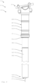
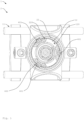
- FIGS. 2 to 5 show a bicycle component 1 according to the invention in various representations.
- the bicycle component 1 will be discussed below with reference to Figures 2 to 5 described in more detail.
- the bicycle component 1 comprises a seat support device 2 with a first or lower support element 12 and a second or upper support element 22.
- the two support elements 12, 22 are telescopic.
- the upper support element 22 is here equipped with a saddle holder 11, via which a saddle is attached to the Seat support device 2 can be mounted.
- the first support element 22 can be firmly attached to the frame structure of the bicycle.
- a seal 31 or an O-ring is arranged at the end of the upper support element 22 opposite the saddle receptacle 11. To accommodate the seal 31, the upper support element 22 has a collar.
- a dirt deflector 21 is arranged here at the end of the support element 22 opposite the saddle receptacle 11. This means that impurities are stripped off when immersed.
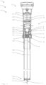
- the locking device 3 is here essentially arranged within the first support element 12.
- the locking device 3 here comprises a plurality of locking elements 4, of which only two can be seen here.
- the locking elements 4 are designed here as balls 14.
- a respective locking element 4 runs through a wall 121 of the first support element 12.
- the wall 121 has a through opening 303.
- the locking element 4 extends further into part of a wall 221 of the second support element 22.
- a recess 222 for the locking element 4 is incorporated there.
- the wall 221 is equipped with an outward-pointing projection 223.
- the recess 122 here is designed to be circumferential or ring-like. However, an embodiment is also possible in which a corresponding recess 202 20 is provided for each of the locking elements 4.
- the locking elements 4 are pressed into the recess 222 by a piston element 5 or by a cone 51 of the piston element 5. In this position, the locking elements 4 prevent the second or upper support element 22 from being able to lower further. The saddle height or the position of the two support elements 12, 22 relative to one another is thus locked. The piston element 5 and the locking elements 4 are in a locked or locked position. Here is the upper position 10 of the bicycle component 1 or the seat post or seat support device 2 shown. The locking elements 4 are locked in the lower recesses 222 of the second support element 22.
- the piston element 5 In order to release the locking device 3 and retract the seat support device 2, the piston element 5 is pulled downwards in the direction of the longitudinal axis of the support elements 12, 22. Then the piston element 5 is moved into a release position. In the release position, the saddle height can be reduced by applying appropriate pressure on the saddle, for example with the buttocks.
- the piston element 5 is conical here, so that it becomes narrower towards the upper end. If the piston element 5 is moved downwards, it no longer presses the locking elements 4 (via the cone 51) into the recess 222. This means that the upper support element 22 can slide over the lower support element 12.
- the locking device 3 In order to lock the saddle height in the retracted, lower position 20, the locking device 3 here comprises an additional, higher recess 222. There the locking elements 4 can be pressed in by the piston element 5, so that the saddle support device 2 is locked in this position.
- the bicycle component 1 here comprises a force storage device 9 designed as a spring 19, which is preloaded when the seat support device 2 is retracted.
- the spring 19 is designed as a compression spring.
- the locking device 3 is here equipped with a pretensioning device 8.
- the clamping device 8 here comprises a spring 18, which automatically presses the piston element 5 into the locked position.
- the piston element 5 is moved here with an actuating device 6 with a cable pull device 7 between the release position and the locked position.
- the piston element 5 is pulled downwards with a cable 17 of the cable pull device 7.
- the piston element 5 remains in the release position and the locking elements 4 are not pressed into the recess 222. If the cable 17 is relaxed, the pretensioning device 8 pushes the piston unit 5 back into the locked position.
- control panel 16 As with reference to Figure 1 described.
- the cable 17 runs here through the lower support element 12 and leaves it at one end 122, which can be received in the seat tube 104 of the bicycle 100.
- the cable pull 17 emerges from the support element at an axial end face 123 out of.
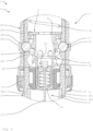
- the first support element 12 is here composed of two tubular support sections 301, 302 which are connected to one another in a connection region 300.
- the support sections 301, 302 are arranged in an overlapping manner in the connection area 300.
- the upper support section 301 in the operational state has a greater wall thickness than the lower support section 302.
- the through opening 303 for the locking elements 4 is located in the upper support section 301.
- the piston element 5 is guided in the upper support section 301.
- the first support element 12 here has an outer contour 120, which is matched to an inner contour 220 of the second support element.
- the outer contour 120 of the first support element 12 is provided here by the two support sections 301 and 302. In this way, the upper support element 22 can be pushed over the connection area 300 easily and without tilting.
- an end position cushioning 23 is provided in the area of the upper end of the second support element 22 in the area of the upper end of the second support element 22, an end position cushioning 23 is provided. End position cushioning can also be provided at the lower end.
- the cable pull 17 is coupled to a cable tensioner 24. This means that the user always receives defined haptic feedback when touching or moving the actuating device.
- the cable tensioner 24 includes a pretensioning unit 25 and a sliding element 26, which is axially guided within the piston element.
- the sliding element is secured via the preload unit pressed into a pre-tensioned state and always keeps the rope taut.
- the two support elements 12, 22 have a substantially round outer contour 120 or inner contour 220.
- an anti-twist device 400 with three guide elements 401 is provided here.
- the guide elements 401 are arranged here between the two support elements 12, 22.
- the two support elements 12, 22 are connected to one another in a rotationally fixed manner.
- the seat support device 2 shown here can also include a damper device for damping the telescoping movement.
- the piston element 5 is then designed as a valve piston, which influences a flow of a damper fluid.
Landscapes
- Engineering & Computer Science (AREA)
- Mechanical Engineering (AREA)
- Motorcycle And Bicycle Frame (AREA)
- Steering Devices For Bicycles And Motorcycles (AREA)
Description
Die vorliegende Erfindung betrifft eine Fahrradkomponente für ein wenigstens teilweise mit Muskelkraft betriebenes Fahrrad mit einer zwischen wenigstens zwei Stellungen teleskopartig verstellbaren Sattelstützeinrichtung zum Anpassen einer Sattelhöhe.The present invention relates to a bicycle component for a bicycle that is at least partially powered by muscle power and has a seat support device that can be adjusted telescopically between at least two positions for adjusting a saddle height.
Für eine sichere Beherrschung eines Fahrrads und für eine günstige Kraftübertragung ist es wichtig, dass die Sattelhöhe optimal eingestellt ist. Das gilt sowohl für Alltags- bzw. Cityräder als auch für Sportfahrräder. Oft ist es hilfreich, die Sattelhöhe an die unterschiedlichen Fahrsituationen einfach und zügig anpassen zu können.For safe control of a bicycle and for efficient power transmission, it is important that the saddle height is optimally adjusted. This applies to everyday or city bikes as well as sports bikes. It is often helpful to be able to quickly and easily adjust the saddle height to different driving situations.
Beispielsweise muss bei Bergabfahrten der Sattel entsprechend tief stehen, damit der Fahrer sein Gewicht hinter den Sattel bringen kann, um den Schwerpunkt nach hinten zu verlagern. Beim Fahren in der Sitzposition muss die Sattelhöhe ergonomisch eingestellt sein, um einen günstigen Krafteintrag in den Antrieb zu ermöglichen.For example, when driving downhill, the saddle must be appropriately low so that the rider can put his weight behind the saddle in order to shift the center of gravity backwards. When riding in the sitting position, the saddle height must be adjusted ergonomically to enable a favorable input of force into the drive.
Daher werden Fahrräder immer häufiger mit verstellbaren Sattelstützen ausgestattet, welche auch als Teleskopstützen bezeichnet werden. Bei solchen Teleskopstützen werden zwei teleskopierende Rohre eingesetzt, wobei das dickere Rohr unten in den Rahmen eingesetzt wird und das dünnere Rohr nach oben aus dem dickeren Rohr heraussteht. Dadurch kann ein sehr großer Verstellbereich zur Verfügung gestellt werden, da das innere Rohr nahezu beliebig tief in den Fahrradrahmen eintauchen kann. Zur Verstellung kann der Fahrer den Verstellmechanismus der Sattelstütze in der Regel vom Lenker aus bedienen. So kann eine Anpassung der Sattelhöhe während der Fahrt erfolgen, ohne dass der Fahrer absteigen muss. Eine gattungsgemäße Fahrradkomponente mit einer solchen Sattelstütze ist aus der
Hydraulische Sattelstützen erlauben eine Verstellung in unterschiedlichste Höhenpositionen. Ein Nachteil daran ist aber, dass diese schwierig zu demontieren und zu säubern und zu warten sind. Für die Demontage ist Spezialwerkzeug nötig. Außerdem kann Hydraulikfluid austreten, wenn die Demontage nicht fachgerecht erfolgt.Hydraulic seat supports allow adjustment to a wide variety of height positions. One disadvantage, however, is that they are difficult to dismantle, clean and maintain. Special tools are required for dismantling. In addition, hydraulic fluid can leak if disassembly is not carried out properly.
Die bekannten verstellbaren Sattelstützen funktionieren in der Regel zufriedenstellend, bieten jedoch auch Verbesserungspotenzial. Insbesondere können die bekannten Lösungen hinsichtlich ihrer Praxistauglichkeit und ihres Gewichts sowie ihrer Herstellungskosten und insbesondere des Wartungsaufwandes optimiert werden.The well-known adjustable seat posts generally work satisfactorily, but also offer potential for improvement. In particular, the known solutions can be optimized in terms of their practical suitability and their weight as well as their manufacturing costs and in particular the maintenance effort.
Es ist daher die Aufgabe der vorliegenden Erfindung, eine verbesserte Fahrradkomponente mit einer verstellbaren Sattelstützeinrichtung zur Verfügung zu stellen. Insbesondere soll eine verstellbare Sattelstütze zur Verfügung gestellt werden, welche zuverlässig ist und unkompliziert funktioniert und wirtschaftlich herstellbar ist und insbesondere einfach zu warten ist.It is therefore the object of the present invention to provide an improved bicycle component with an adjustable seat support device. In particular, an adjustable seat post is to be provided which is reliable and functions in an uncomplicated manner and is economical to produce and, in particular, is easy to maintain.
Diese Aufgabe wird gelöst durch eine Fahrradkomponente mit den Merkmalen des Anspruchs 1 sowie durch ein Fahrrad gemäß Anspruch 15. Bevorzugte Weiterbildungen sind Gegenstand der Unteransprüche. Weitere Vorteile und Merkmale der vorliegenden Erfindung ergeben sich aus der allgemeinen Beschreibung und der Beschreibung der Ausführungsbeispiele.This task is solved by a bicycle component with the features of
Die erfindungsgemäße Fahrradkomponente ist für ein wenigstens teilweise mit Muskelkraft betriebenes Fahrrad vorgesehen. Die Fahrradkomponente umfasst eine zwischen wenigstens zwei Stellungen teleskopartig verstellbare Sattelstützeinrichtung zum Anpassen einer Sattelhöhe. Die Fahrradkomponente umfasst wenigstens eine Verriegelungseinrichtung zum Arretieren der Sattelstützeinrichtung in wenigstens einer der Stellungen. Die Sattelstützeinrichtung umfasst wenigstens zwei relativ zueinander bewegbare Stützelemente, nämlich en erstes Stützelement und wenigstens ein zweites Stützelement. Das erste Stützelement ist an einer Rahmenstruktur des Fahrrad; fest befestigbar.The bicycle component according to the invention is intended for a bicycle that is at least partially powered by muscle power. The bicycle component comprises a seat support device that is telescopically adjustable between at least two positions for adjusting a saddle height. The bicycle component comprises at least one locking device for locking the seat support device in at least one of the positions. The seat support device comprises at least two support elements that are movable relative to one another, namely a first support element and at least one second support element. The first support element is on a frame structure of the bicycle; can be firmly attached.
Das zweite Stützelement dient zur Aufnahme eines Sattels. Dabei ist das erste Stützelement wenigstens abschnittsweise innerhalb des zweiten Stützelements angeordnet. Zum Teleskopieren der Sattelstützeinrichtung ist das zweite Stützelement wenigstens abschnittsweise über das erste Stützelement bewegbar. Eine solche "upside-down"-Ausgestaltung ermöglicht einen sehr einfachen Aufbau. Dabei ist das zweite Stützelement einwandig ausgebildet. Dabei ist die Verriegelungseinrichtung wenigstens teilweise innerhalb des ersten Stützelements angeordnet und umfasst wenigstens ein Riegelelement, welches sich im arretierten Zustand durch wenigstens eine Wandung des ersten Stützelements hindurch in das zweite Stützelement erstreckt. Besonders bevorzugt gleitet das zweite Stützelement bei einer Höhenverstellung (eines Sattels) auf dem ersten Stützelement und/oder wird durch das erste Stützelement geführt.The second support element is used to hold a saddle. The first support element is arranged at least in sections within the second support element. To telescope the seat support device, the second support element can be moved at least in sections over the first support element. Such an “upside-down” design enables a very simple structure. The second support element is designed to be single-walled. The locking device is at least partially arranged within the first support element and comprises at least one locking element which, in the locked state, extends through at least one wall of the first support element into the second support element. Particularly preferably, the second support element slides on the first support element during a height adjustment (of a saddle) and/or is guided through the first support element.
Die erfindungsgemäße Fahrradkomponente bietet viele Vorteile. Einen erheblichen Vorteil bietet die erfindungsgemäße Anordnung der beiden Stützelemente. Dadurch kann das zweite bzw. obere Stützelement konstruktiv unabhängig von der Rahmenstruktur und insbesondere vom Sattelrohrdurchmesser ausgelegt werden. Dadurch ergeben sich wesentliche höhere Freiheitsgrade für die Konstruktion und erheblich flexiblere Ausgestaltungsmöglichkeiten, um eine zuverlässige und kostenoptimierte Sattelstützeinrichtung zu erhalten. Besonders vorteilhaft ist zudem, dass die erfindungsgemäße Fahrradkomponente dadurch besonders gut auch bei anderen Arten von Fährrädern als Mountainbikes eingesetzt werden kann, z. B. bei Rennrädern, Cyclo-Cross-Rädern und Trekkingrädern und E-Bikes.The bicycle component according to the invention offers many advantages. The arrangement of the two support elements according to the invention offers a significant advantage. This allows the second or upper support element can be designed structurally independently of the frame structure and in particular of the seat tube diameter. This results in significantly higher degrees of freedom for the design and significantly more flexible design options in order to obtain a reliable and cost-optimized seat support device. It is also particularly advantageous that the bicycle component according to the invention can therefore also be used particularly well in other types of ferry bikes than mountain bikes, e.g. B. on racing bikes, cyclo-cross bikes and trekking bikes and e-bikes.
Zum Beispiel sind mit der Erfindung erheblich größere Durchmesser für das zweite bzw. obere Stützelement möglich. Dadurch ergibt sich auch eine freiere Werkstoffwahl der Stützelemente. Die erfindungsgemäße Fahrradkomponente ermöglicht daher auch eine vorteilhafte Gewichtsreduzierung, was besonders bei Sporträdern von Vorteil ist. Ein weiterer Vorteil ist, dass sich höhere Freiheitsgrade für die Montage des Sattels an dem zweiten Stützelement ergeben. Bisher konnte der obere Teil von teleskopierbaren Sattelstützen nur in sehr engen Grenzen konstruiert werden, da dieser einen besonders geringen Durchmesser aufweisen musste, um beim Einfahren des Sattels in das untere Teil zu passen. Dabei konnte der untere Teil auch nicht einfach vergrößert werden, da dieser wiederum in das Sattelrohr des Rahmens passen muss.For example, significantly larger diameters for the second or upper support element are possible with the invention. This also results in a freer choice of material for the support elements. The bicycle component according to the invention therefore also enables an advantageous weight reduction, which is particularly advantageous for sports bikes. Another advantage is that there are higher degrees of freedom for mounting the saddle on the second support element. Until now, the upper part of telescopic seat posts could only be designed within very narrow limits, as it had to have a particularly small diameter in order to fit into the lower part when the saddle was retracted. The lower part couldn't simply be enlarged because it has to fit into the seat tube of the frame.
In allen Ausgestaltungen ist es bevorzugt, dass das erste Stützelement aus einem leichten Material besteht. Es ist möglich, dass das erste und/oder das zweite Stützelement wenigstens zum Teil oder auch vollständig aus einem faserverstärkten Material wie einem Carbonmaterial besteht. Besonders bevorzugt besteht das erste Stützelement wenigstens teilweise und insbesondere wenigstens zu einem erheblichen Teil oder im Wesentlichen vollständig oder vollständig aus (wenigstens) einem Faserverbundmaterial.In all configurations, it is preferred that the first support element consists of a light material. It is possible for the first and/or the second support element to consist at least partially or completely of a fiber-reinforced material such as a carbon material. Particularly preferably, the first support element consists at least partially and in particular at least to a significant extent or essentially completely or completely (at least) one fiber composite material.
Auch für das erste bzw. untere Stützelement werden flexiblere Konstruktionsbedingungen ermöglicht. Zum Beispiel kann die Wandstärke des ersten Stützelements unabhängig von den Abmessungen des oberen Stützelements ausgelegt werden. So kann das erste bzw. untere Stützelement beispielsweise in optimaler Leichtbauweise ausgeführt werden. Bislang musste der untere Teil von teleskopierbaren Sattelstützen so dünnwandig ausgeführt werden, dass der obere Teil eintauchen konnte, damit ein Teleskopieren möglich ist. Das untere Stützelement kann z. b. so groß ausgeführt werden, dass es passgenau in das Sattelrohr einsetzbar ist. Dadurch ergibt sich eine insgesamt erheblich steifere und belastbare und zugleich gewichtsoptimierte Sattelstützeinrichtung.More flexible construction conditions are also made possible for the first or lower support element. For example, the wall thickness of the first support element can be designed independently of the dimensions of the upper support element. For example, the first or lower support element can be designed with an optimal lightweight construction. Until now, the lower part of telescopic seat posts had to be made so thin-walled that the upper part could be immersed in order to make telescoping possible. The lower support element can z. b. be made so large that it can be inserted precisely into the seat tube. This results in an overall considerably stiffer and more resilient and at the same time weight-optimized seat support device.
Ein weiterer Vorteil ist, dass durch die erfindungsgemäße Anordnung der beiden Stützelemente die Sattelstützeinrichtung erheblich unempfindlicher gegen Verschmutzungen ist und somit eine besonders zuverlässige Funktion bietet. Dadurch, dass das obere Stützelement über das untere Stützelement bewegbar ist, kann Schmutz wesentlich leichter abgestreift werden und einfach nach unten fallen. Schmutz und Feuchtigkeit sammelt sich insbesondere nicht oben direkt auf der Verbindungsstelle der beiden Stützelemente, sondern wird davon nach unten abgestreift.Another advantage is that the inventive arrangement of the two support elements means that the seat support device is considerably less sensitive to contamination and therefore offers a particularly reliable function. Because the upper support element can be moved over the lower support element, dirt can be wiped off much more easily and simply fall down. In particular, dirt and moisture do not collect directly at the top of the connection point between the two support elements, but are wiped off downwards.
Im Rahmen der vorliegenden Erfindung wird unter dem Begriff Teleskopieren insbesondere ein relatives Ineinanderschieben der Stützelemente verstanden. Zum Teleskopieren der Sattelstützeinrichtung, vorzugsweise zum Verringern der Sattelhöhe, ist insbesondere das zweite Stützelement wenigstens abschnittsweise über das ersteStützelement schiebbar. Zum Teleskopieren der Sattelstützeinrichtung, vorzugsweise zum Vergrößern der Sattelhöhe, wird insbesondere das zweite Stützelement wenigstens abschnittsweise auf dem ersten Stützelement nach oben bewegt. Insbesondere teleskopiert das erste Stützelement in das zweite Stützelement bzw. das zweite Stützelement bewegt sich auf dem ersten Stützelement.In the context of the present invention, the term telescoping is understood to mean, in particular, a relative telescoping of the support elements. To telescope the seat support device, preferably to reduce the saddle height, the second support element in particular can be pushed over the first support element at least in sections. To telescope the seat support device, preferably to increase the saddle height, in particular the second support element moves upwards at least in sections on the first support element. In particular, the first support element telescopes into the second support element or the second support element moves on the first support element.
Die Fahrradkomponente kann in einfachen Ausgestaltungen als Sattelstütze ausgebildet sein.In simple configurations, the bicycle component can be designed as a seat post.
Vorzugsweise sind rohrartige Stützelemente vorgesehen. Vorzugsweise sind die Stützelemente wenigstens teilweise hohl ausgebildet.Tubular support elements are preferably provided. Preferably, the support elements are at least partially hollow.
Bei einer betriebsgemäßen Verwendung der Sattelstützeinrichtung ist das zweite Stützelement insbesondere oben und das erste Stützelement insbesondere unten angeordnet. Dabei ist das erste Stützelement insbesondere wenigstens abschnittsweise in einem Sattelrohr einer Rahmenstruktur eines Fahrrads aufgenommen. Die Rahmenstruktur kann Teil der Fahrradkomponente sein. Die Fahrradkomponente kann auch ein Fahrrad umfassen oder als ein solches ausgebildet sein.When the seat support device is used properly, the second support element is arranged in particular at the top and the first support element is arranged in particular at the bottom. The first support element is in particular accommodated at least in sections in a seat tube of a frame structure of a bicycle. The frame structure can be part of the bicycle component. The bicycle component can also include a bicycle or be designed as such.
Vorzugsweise sind wenigstens eine Außenkontur des ersten Stützelements und wenigstens eine Innenkontur des zweiten Stützelements, d.h. die Buchsen des jeweiligen Stützelementes, wenigstens abschnittsweise passgenau zueinander ausgebildet, sodass das zweite Stützelement entlang des ersten Stützelements geführt ist. Das bietet ein leichtgängiges und robustes Ein- und Ausfahren der Sattelstützeinrichtung. Insbesondere sind die Außenkontur und die Innenkontur dort passgenau zueinander ausgebildet, wo die beiden Stützelemente aneinander entlang gleiten bzw. teleskopieren. Insbesondere ist das erste Stützelement in dem zweiten Stützelement geführt bzw. es wird das zweite Stützelement außen auf dem ersten Stützelement geführt. Das erste Stützelement kann ein fester Bestandteil der Rahmenstruktur des Fahrrads oder des Fahrradrahmens sein und kann fest damit verbunden oder einstückig damit gearbeitet sein.Preferably, at least one outer contour of the first support element and at least one inner contour of the second support element, ie the bushings of the respective support element, are designed to fit one another at least in sections, so that the second support element is guided along the first support element. This offers smooth and robust retraction and extension of the seat support device. In particular, the outer contour and the inner contour are designed to fit one another exactly where the two support elements slide or telescope along one another. In particular, the first support element is guided in the second support element or the second support element is on the outside of the first Support element guided. The first support element can be an integral part of the frame structure of the bicycle or the bicycle frame and can be firmly connected to it or made in one piece with it.
Es ist möglich, dass zwischen den beiden Stützelementen wenigstens eine Verdrehsicherung angeordnet ist. Dadurch wird verhindert, dass sich der Sattel im Betrieb und auch beim Absenken bzw. Auseinanderfahren der Sattelstützeinrichtung verdreht. Die Verdrehsicherung wird insbesondere durch die Außenkontur des ersten Stützelements und die Innenkontur des zweiten Stützelements bereitgestellt.It is possible for at least one anti-rotation device to be arranged between the two support elements. This prevents the saddle from twisting during operation and also when lowering or extending the seat support device. The anti-twist protection is provided in particular by the outer contour of the first support element and the inner contour of the second support element.
Die Verdrehsicherung kann auch wenigstens eine Linearführung mit wenigstens einer Führungsschiene umfassen. Die Führungsschiene ist beispielsweise in eine Vertiefung im ersten oder zweiten Stützelement eingelassen. Die Verdrehsicherung kann auch wenigstens eine Verzahnung aufweisen. Möglich ist auch eine anders ausgestaltete Verdrehsicherung. Besonders bevorzugt ermöglicht die Verdrehsicherung eine leichtgängige Verstellung. Insbesondere ist die Verdrehsicherung im Wesentlichen spielfrei oder (praktisch) spielfrei ausgestaltet.The anti-rotation device can also include at least one linear guide with at least one guide rail. The guide rail is, for example, embedded in a recess in the first or second support element. The anti-rotation device can also have at least one toothing. A differently designed anti-twist device is also possible. Particularly preferably, the anti-twist device enables smooth adjustment. In particular, the anti-twist device is designed to be essentially free of play or (practically) free of play.
Insbesondere sind die Stützelemente zylindrisch ausgebildet. Insbesondere ist ein Außendurchmesser des ersten Stützelements kleiner als ein Innendurchmesser des zweiten Stützelements. Die Stützelemente können auch wenigstens abschnittsweise unrund ausgebildet sein.In particular, the support elements are cylindrical. In particular, an outer diameter of the first support element is smaller than an inner diameter of the second support element. The support elements can also be designed to be out of round at least in sections.
Die Verriegelungseinrichtung ist vorzugsweise wenigstens teilweise innerhalb eines der Stützelemente und insbesondere innerhalb des ersten Stützelements angeordnet. Das bietet eine besonders kompakte Sattelstützeinrichtung und eine wartungsarme Unterbringung. Beispielsweise ist in dem ersten Stützelement wenigstens ein Aufnahmeraum angeordnet, in welchem die Verriegelungseinrichtung wenigstens teilweise angeordnet ist. Insbesondere ist die Verriegelungseinrichtung in einem derartigen Umfang in dem ersten Stützelement angeordnet, dass nur das wenigstens eine Riegelelement nicht innerhalb des ersten Stützelements bzw. außerhalb des ersten Stützelements angeordnet ist. Die Verriegelungseinrichtung kann auch wenigstens teilweise in dem zweiten Stützelement angeordnet sein.The locking device is preferably arranged at least partially within one of the support elements and in particular within the first support element. This offers a particularly compact seat support device and low-maintenance accommodation. For example, in the first Support element arranged at least one receiving space in which the locking device is at least partially arranged. In particular, the locking device is arranged in the first support element to such an extent that only the at least one locking element is not arranged inside the first support element or outside of the first support element. The locking device can also be arranged at least partially in the second support element.
Die Verriegelungseinrichtung umfasst bevorzugt wenigstens ein Riegelelement. Das Riegelelement erstreckt sich im arretierten Zustand insbesondere durch wenigstens eine Wandung des ersten Stützelements hindurch in das zweite Stützelement. Das bietet eine konstruktiv unaufwändige und zugleich sehr zuverlässige Verriegelung und ermöglicht eine spielfreie Realisierung. Insbesondere erstreckt sich das Riegelelement im arretierten Zustand in wenigstens eine Wandung des zweiten Stützelements. Zum Durchführen des Riegelelements kann das erste Stützelement wenigstens eine Durchgangsöffnung umfassen. Beispielsweise ist in der Wandung wenigstens eine Bohrung angeordnet. Insbesondere ist eine Mehrzahl von Riegelelementen vorgesehen. Die Verriegelungseinrichtung ist insbesondere dazu geeignet und ausgebildet, eine relative Bewegbarkeit der Stützelemente zueinander mittels des Riegelelements formschlüssig zu blockieren.The locking device preferably comprises at least one locking element. In the locked state, the locking element extends in particular through at least one wall of the first support element into the second support element. This offers a structurally simple and at the same time very reliable locking and enables play-free implementation. In particular, in the locked state, the locking element extends into at least one wall of the second support element. To pass through the locking element, the first support element can comprise at least one through opening. For example, at least one hole is arranged in the wall. In particular, a plurality of locking elements is provided. The locking device is particularly suitable and designed to positively block relative mobility of the support elements to one another by means of the locking element.
Im arretierten Zustand erstreckt sich das Riegelelement insbesondere nur in einen Teil einer Wandung des zweiten Stützelements. Das hat den Vorteil, dass eine geschlossene Außenhülle bereitgestellt wird, durch welche kein Schmutz eindringen kann. Insbesondere umfasst das zweite Stützelement wenigstens eine Ausnehmung in der Wandung, in welcher das Riegelelement im arretierten Zustand angeordnet ist. Die Ausnehmung ist beispielsweise als eine Vertiefung bzw. Senke ausgebildet. Möglich ist aber auch, dass das Riegelelement im arretierten Zustand durch die Wandung des zweiten Stützelements hindurchtritt.In the locked state, the locking element extends in particular only into part of a wall of the second support element. This has the advantage that a closed outer shell is provided through which no dirt can penetrate. In particular, the second support element comprises at least one recess in the wall in which the locking element is arranged in the locked state. The Recess is designed, for example, as a depression or depression. However, it is also possible for the locking element to pass through the wall of the second support element in the locked state.
Die Verriegelungseinrichtung ist insbesondere dazu geeignet und ausgebildet, das Riegelelement mittels wenigstens eines Kolbenelements wenigstens teilweise in wenigstens eine Ausnehmung des zweiten Stützelements zu drücken. So wird ein zuverlässiges Positionieren der Riegelelemente erreicht. Insbesondere liegt eine arretierte Stellung vor, wenn das Kolbenelement das Riegelelement in das zweite Stützelement drückt. Insbesondere drückt das Kolbenelement das Riegelelement in die Ausnehmung des zweiten Stützelements. Insbesondere umfasst die Verriegelungseinrichtung wenigstens ein Kolbenelement. Die Ausnehmung ist insbesondere in der Wandung des zweiten Stützelements angeordnet.The locking device is particularly suitable and designed to at least partially press the locking element into at least one recess in the second support element by means of at least one piston element. This ensures reliable positioning of the locking elements. In particular, a locked position exists when the piston element presses the locking element into the second support element. In particular, the piston element presses the locking element into the recess of the second support element. In particular, the locking device comprises at least one piston element. The recess is arranged in particular in the wall of the second support element.
Das Kolbenelement ist insbesondere in Richtung einer Längsachse der Stützelemente bewegbar. Insbesondere drückt das Kolbenelement das Riegelelement quer zur Längsachse des Stützelementes. Insbesondere umfasst das Kolbenelement wenigstens eine Keilfläche, mit der eine Längsbewegung des Kolbenelements in eine Querbewegung des Riegelelements umsetzbar ist. Beispielsweise ist das Kolbenelement stabförmig und/oder zylindrisch ausgebildet. Bei einer wenigstens abschnittsweise zylindrischen Ausgestaltung des Kolbenelements ist vorzugsweise die Keilfläche an einem Konus ausgebildet und ist konusförmig gestaltet. Möglich ist auch, dass das Kolbenelement ringförmig und/oder als eine Buchse ausgebildet ist. Insbesondere ist das Keilelement an einen Innendurchmesser und/oder eine Innenkontur des ersten Stützelements angepasst. Insbesondere ist das Kolbenelement in dem ersten Stützelement geführt und vorzugsweise linear geführt.The piston element is movable in particular in the direction of a longitudinal axis of the support elements. In particular, the piston element presses the locking element transversely to the longitudinal axis of the support element. In particular, the piston element comprises at least one wedge surface with which a longitudinal movement of the piston element can be converted into a transverse movement of the locking element. For example, the piston element is rod-shaped and/or cylindrical. In the case of an at least partially cylindrical design of the piston element, the wedge surface is preferably formed on a cone and is designed in a conical shape. It is also possible for the piston element to be annular and/or designed as a bushing. In particular, the wedge element is adapted to an inner diameter and/or an inner contour of the first support element. In particular, the piston element is guided in the first support element and is preferably linear guided.
Das Riegelelement bzw. die Riegelelemente ist bzw. sind vorzugsweise lose eingelegt und werden insbesondere nicht geführt.The locking element or the locking elements is or are preferably inserted loosely and are in particular not guided.
Das Kolbenelement ist vorzugsweise in Richtung einer Längsachse des ersten Stützelements in wenigstens eine Lösestellung bewegbar. Vorzugsweise drückt das Kolbenelement in der Lösestellung das Riegelelement nicht in das zweite Stützelement. Das bietet eine Verriegelung, welche unaufwendig ist und zuverlässig funktioniert. Insbesondere weist das Kolbenelement wenigstens eine Aussparung auf, in welcher das Riegelelement in der Lösestellung aufnehmbar ist. Insbesondere ist das Riegelelement in der Lösestellung nicht mehr in (der Wandung von) dem zweiten Stützelement angeordnet.The piston element is preferably movable into at least one release position in the direction of a longitudinal axis of the first support element. Preferably, the piston element does not press the locking element into the second support element in the release position. This offers a lock that is inexpensive and works reliably. In particular, the piston element has at least one recess in which the locking element can be received in the release position. In particular, the locking element is no longer arranged in (the wall of) the second support element in the release position.
Die Fahrradkomponente umfasst insbesondere wenigstens eine Betätigungseinrichtung zum Lösen und/oder Aktivieren der Arretierung. Dabei ist die Betätigungseinrichtung insbesondere dazu geeignet und ausgebildet, das Kolbenelement in die Lösestellung und/oder in die arretierte Stellung zu bewegen. Die Betätigungseinrichtung kann wenigstens teilweise manuell oder auch vollständig manuell betätigbar sein. Möglich ist auch eine motorisch unterstützte und/oder vollautomatische Betätigung und/oder eine kabellose Betätigung und Funktionsweise. In bevorzugten Ausgestaltungen wird eine mechanische Lösung realisiert, auch wenn es sich vorbehalten wird, elektrische und/oder ferngesteuerte und/oder kabellose Steuerungsmöglichkeiten zu realisieren, wenn diese technisch möglich und rechtlich zulässig sind.The bicycle component in particular comprises at least one actuating device for releasing and/or activating the locking mechanism. The actuating device is particularly suitable and designed to move the piston element into the release position and/or into the locked position. The actuating device can be at least partially manually or completely manually operable. Motor-assisted and/or fully automatic operation and/or wireless operation and functionality are also possible. In preferred embodiments, a mechanical solution is implemented, although it is reserved to implement electrical and/or remote-controlled and/or wireless control options if these are technically possible and legally permissible.
Besonders bevorzugt ist das Kolbenelement zum Einnehmen der Lösestellung in Richtung eines von dem zweiten Stützelement abgewandten Endes des ersten Stützelements bzw. eines in der Rahmenstruktur aufnehmbaren Endes des ersten Stützelements bewegbar. Insbesondere ist das Kolbenelement zum Einnehmen der Lösestellung in Richtung eines von dem zweiten Stützelement abgewandten Endes des ersten Stützelements durch ein Ziehen und vorzugsweise durch wenigstens eine Seilzugeinrichtung bewegbar. Das ermöglicht eine besonders Bauraum sparende Unterbringung der Betätigungseinrichtung. Für das Einnehmen der Lösestellung ist das Keilelement insbesondere in Richtung desjenigen Endes des ersten Stützelements bewegbar, welches dem mit dem zweiten Stützelement verbundenen Ende des ersten Stützelements gegenüberliegt. Das Keilelement ist insbesondere aus der arretierten Stellung in die Lösestellung überführbar, indem es zu dem Ende des ersten Stützelements bewegt wird, welches in der Rahmenstruktur aufnehmbar ist.Particularly preferred is the piston element for assuming the release position in the direction of an end of the first support element facing away from the second support element or one in the Frame structure removable end of the first support element movable. In particular, the piston element can be moved to assume the release position in the direction of an end of the first support element facing away from the second support element by pulling and preferably by at least one cable pull device. This enables the actuating device to be accommodated in a particularly space-saving manner. To assume the release position, the wedge element can be moved in particular in the direction of that end of the first support element which is opposite the end of the first support element connected to the second support element. The wedge element can in particular be moved from the locked position into the release position by moving it to the end of the first support element, which can be received in the frame structure.
Das Kolbenelement ist besonders bevorzugt dazu geeignet und ausgebildet, mittels wenigstens einer Betätigungseinrichtung in die Lösestellung gezogen zu werden. Eine solches Ziehen kann besonders unaufwendig und robust umgesetzt werden.The piston element is particularly preferably suitable and designed to be pulled into the release position by means of at least one actuating device. Such pulling can be implemented particularly inexpensively and robustly.
Insbesondere wird das Kolbenelement mit der Betätigungseinrichtung zu einem Ende des ersten Stützelements gezogen, welches in der Rahmenstruktur aufnehmbar ist bzw. welches von dem zweiten Stützelement abgewandt ist. Möglich ist auch, dass das Kolbenelement mittels der Betätigungseinrichtung in die Lösestellung drückbar ist.In particular, the piston element is pulled with the actuating device to an end of the first support element, which can be received in the frame structure or which faces away from the second support element. It is also possible for the piston element to be pressed into the release position by means of the actuating device.
In allen Ausgestaltungen ist es bevorzugt, dass die Fahrradkomponente wenigstens eine Betätigungseinrichtung zum Lösen und/oder Aktivieren der Verriegelungseinrichtung umfasst. Die Betätigungseinrichtung ist dabei insbesondere die zuvor beschriebene Betätigungseinrichtung, mittels der das Kolbenelement in die Lösestellung gezogen wird. Vorzugsweise ist die Betätigungseinrichtung wenigstens teilweise mechanisch ausgebildet. Die Betätigungseinrichtung kann vollständig mechanisch ausgebildet sein.In all embodiments, it is preferred that the bicycle component comprises at least one actuation device for releasing and/or activating the locking device. The actuating device is in particular the actuating device described above, by means of which the piston element is pulled into the release position. The actuating device is preferably at least partially mechanical. The actuation device can be complete be mechanically designed.
Vorzugsweise umfasst die Betätigungseinrichtung wenigstens eine Seilzugeinrichtung mit wenigstens einem Seilzug. Die Betätigungseinrichtung kann wenigstens einen mechanischen Bedienhebel umfassen, mit welcher der Seilzug in wenigstens eine Stellung bzw. wenigstens eine der beiden Stellungen (gelöst/arretiert) überführt werden kann. Eine Seilzugeinrichtung bietet viele Vorteile und ist beispielsweise besonders wartungsarm und betriebssicher. Insbesondere ist die Betätigungseinrichtung dazu geeignet und ausgebildet, das Kolbenelement mittels der Seilzugeinrichtung zu ziehen. Der Seilzug verläuft insbesondere innerhalb des ersten Stützelements. Insbesondere verläuft der Seilzug auch innerhalb der Rahmenstruktur und insbesondere eines Sattelrohrs des Fahrrads.Preferably, the actuating device comprises at least one cable pull device with at least one cable pull. The actuating device can comprise at least one mechanical operating lever with which the cable pull can be moved into at least one position or at least one of the two positions (released/locked). A cable pull device offers many advantages and is, for example, particularly low-maintenance and operationally reliable. In particular, the actuating device is suitable and designed to pull the piston element by means of the cable pull device. The cable runs in particular within the first support element. In particular, the cable also runs within the frame structure and in particular a seat tube of the bicycle.
Es hat sich herausgestellt, dass der Seilzug in Stellungen, wenn das Kolbenelement nicht arretiert ist, nicht genau definiert positioniert oder gehalten wird. Dann kann die Betätigungseinrichtung leichtgängig in wenigstens eine Richtung bewegt werden, ohne dass der Benutzer ein haptisches Feedback erhält. Der Benutzer kann dann den Anschein erhalten, dass die Sattelstützeinrichtung nicht definiert arbeitet und gegebenenfalls kann das Vertrauen des Benutzers in die Zuverlässigkeit beeinträchtigt werden. Auch um z. B. einen solchen Eindruck zu vermeiden, kann der Seilzug mit einem Seilstraffer gekoppelt sein, um jederzeit ein definiertes haptisches Feedback für den Benutzer bereitzustellen. Durch den Seilstraffer wird ein ansonsten möglicherweise auftretendes Spiel vermieden.It has been found that the cable pull is not positioned or held in a precisely defined manner in positions when the piston element is not locked. The actuating device can then be moved smoothly in at least one direction without the user receiving haptic feedback. It may then appear to the user that the seat support device is not operating in a defined manner and the user's confidence in its reliability may be compromised. Also around e.g. B. to avoid such an impression, the cable pull can be coupled with a cable tensioner in order to provide defined haptic feedback for the user at all times. The rope tensioner prevents play that might otherwise occur.
Der Seilzug ist vorzugsweise über wenigstens einen Seilstraffer insbesondere mit dem Kolbenelement gekoppelt. Der Seilstraffer umfasst vorzugsweise wenigstens eine Vorspanneinheit, die zu einer Straffung des Seils führt. Die Vorspanneinheit kann als mechanische Feder ausgeführt sein, kann aber auch z.B. auf magnetischer Basis ausgeführt sein. Die Vorspanneinheit ist vorzugsweise an einem Gleitelement angeordnet, an welchem das bzw. ein Ende des Seilzuges gehalten wird. Das Gleitelement wird über die Vorspanneinheit in einen vorgespannten Zustand gedrückt.The cable pull is preferably coupled in particular to the piston element via at least one cable tensioner. The rope tensioner preferably comprises at least one Pre-tensioning unit that leads to a tightening of the rope. The biasing unit can be designed as a mechanical spring, but can also be designed, for example, on a magnetic basis. The pretensioning unit is preferably arranged on a sliding element on which the or one end of the cable is held. The sliding element is pressed into a prestressed state via the prestressing unit.
Eine Vorspannkraft der Vorspanneinheit ist einer Vorspannung der Vorspanneinrichtung entgegengesetzt. Die Höhe der Vorspannkraft der Vorspanneinheit ist aber vorzugsweise erheblich geringer als eine Höhe der Vorspannkraft der Vorspanneinrichtung, sodass immer eine effektive Kraft der Vorspanneinrichtung wirkt. Vorzugsweise ist die Vorspannkraft der Vorspanneinheit kleiner als halb so groß beträgt insbesondere weniger als ein Viertel oder Achtel der Vorspannkraft der Vorspanneinrichtung.A pretensioning force of the pretensioning unit is opposite to a pretensioning of the pretensioning device. However, the level of the prestressing force of the prestressing unit is preferably significantly lower than a level of the prestressing force of the prestressing device, so that an effective force of the prestressing device always acts. Preferably, the prestressing force of the prestressing unit is less than half as large and is in particular less than a quarter or eighth of the prestressing force of the prestressing device.
Die Vorspanneinheit bewirkt, dass in jedem Zustand der Betätigungseinrichtung bzw. in jeder Position des (mechanischen) Bedienhebels eine Kraft zur Spannung des Seilzugs anliegt. Der Benutzer bekommt jederzeit das Feedback einer genau definierten Funktionsweise.The pretensioning unit ensures that a force for tensioning the cable is applied in every state of the actuating device or in every position of the (mechanical) operating lever. The user receives feedback of a precisely defined functionality at any time.
Möglich ist auch, dass die Betätigungseinrichtung wenigstens teilweise hydraulisch ausgebildet ist.It is also possible that the actuating device is at least partially designed to be hydraulic.
Die Betätigungseinrichtung umfasst vorzugsweise wenigstens ein Bedienteil zum Ziehen bzw. Spannen des Seilzugs. Das Bedienteil ist insbesondere an einer Lenkereinrichtung des Fahrers montierbar. Das Bedienteil ist insbesondere auch zum Betätigen und/oder Spannen und/oder Entspannen des Seilzugs ausgebildet. Das Bedienteil kann dazu geeignet und ausgebildet sein, den Seilzug festzustellen, beispielsweise in der Lösestellung und/oder der arretierten Stellung. Der Seilzug kann in eine der beiden Stellungen z. B. durch eine Feder vorbelastet sein.The actuating device preferably comprises at least one control part for pulling or tensioning the cable. The control panel can be mounted in particular on a driver's handlebar device. The operating part is in particular also designed for actuating and/or tensioning and/or relaxing the cable pull. The operating part can be suitable and designed to fix the cable pull, for example in the release position and/or the locked position. The pulley can be in one of the two positions e.g. B. be preloaded by a spring.
Es ist besonders bevorzugt, dass der Seilzug aus einer axialen Stirnseite des ersten Stützelements austritt. Das ermöglicht eine gut geschützte und unaufwendig zu montierende Verlegung des Seilzugs beispielsweise innerhalb der Rahmenstruktur des Fahrrads. Insbesondere tritt der Seilzug an einem Ende des ersten Stützelements aus, welches in der Rahmenstruktur aufnehmbar ist bzw. von dem zweiten Stützelement abgewandt ist. Insbesondere tritt der Seilzug an einem Ende des ersten Stützelements aus, welches in einer betriebsgemäßen Position nach unten bzw. zum Boden gerichtet ist. Insbesondere ist die Seilzugeinrichtung dazu geeignet und ausgebildet, dass der Seilzug innerhalb einer Rahmenstruktur eines Fahrrads und insbesondere wenigstens innerhalb eines Sattelrohrs verlegbar ist. Möglich ist auch, dass der Seilzug an einer radialen Seite des ersten Stützelements austritt.It is particularly preferred that the cable exits from an axial end face of the first support element. This enables the cable to be laid in a well-protected and easy-to-assemble manner, for example within the frame structure of the bicycle. In particular, the cable exits at one end of the first support element, which can be accommodated in the frame structure or is facing away from the second support element. In particular, the cable exits at one end of the first support element, which in an operational position is directed downwards or towards the ground. In particular, the cable pull device is suitable and designed so that the cable pull can be laid within a frame structure of a bicycle and in particular at least within a seat tube. It is also possible for the cable pull to exit on a radial side of the first support element.
Die Fahrradkomponente umfasst insbesondere wenigstens eine Vorbelastungseinrichtung oder eine Vorspanneinrichtung, welche durch ein Ziehen des Kolbenelements in die Lösestellung vorspannbar ist. Die Vorspanneinrichtung insbesondere dazu geeignet und ausgebildet, das Kolbenelement aus der Lösestellung in die arretierte Stellung zu überführen, wenn der Seilzug entspannt wird. Das bietet eine kostengünstig umsetzbare und verlässliche Rückstellung der Verriegelungseinrichtung. Dadurch kann zuverlässig gewährleistet werden, dass der Sattel nach dem Einstellen in der gewünschten Position verbleibt.The bicycle component in particular comprises at least one preloading device or a preloading device, which can be preloaded by pulling the piston element into the release position. The pretensioning device is particularly suitable and designed to move the piston element from the release position into the locked position when the cable pull is relaxed. This offers a cost-effective and reliable reset of the locking device. This can reliably ensure that the saddle remains in the desired position after adjustment.
Die Vorspanneinrichtung umfasst insbesondere wenigstens einen Kraftspeicher und beispielsweise wenigstens eine Feder und/oder Gasfeder. Insbesondere ist das Kolbenelement entgegen einer Vorspannkraft der Vorspanneinrichtung in die Lösestellung bewegbar.The pretensioning device includes in particular at least one energy accumulator and, for example, at least one spring and/or gas spring. In particular, the piston element is in the counter-tensioning force of the pretensioning device Release position movable.
Insbesondere ist die Betätigungseinrichtung dazu geeignet und ausgebildet, das Kolbenelement mittels der Vorspanneinrichtung selbsttätig wieder in die arretierte Stellung zu überführen, wenn an dem Kolbenelement keine Zugspannung mehr anliegt bzw. wenn der Seilzug nicht mehr gezogen wird. Die Vorspanneinrichtung ist insbesondere dazu geeignet und ausgebildet, das Kolbenelement aus der Lösestellung in die arretierte Stellung zu überführen, wenn das Kolbenelement nicht mehr aktiv in der Lösestellung gehalten wird.In particular, the actuating device is suitable and designed to automatically return the piston element to the locked position by means of the pretensioning device when there is no longer any tensile stress on the piston element or when the cable is no longer pulled. The biasing device is particularly suitable and designed to move the piston element from the release position into the locked position when the piston element is no longer actively held in the release position.
In einer vorteilhaften Ausgestaltung umfasst das Riegelelement wenigstens eine Kugel oder ist als wenigstens eine solche ausgebildet. Mit einer solchen Kugel kann besonders unaufwendig und ohne zusätzliche Federn oder dergleichen erreicht werden, dass die Verrieglung aufgehoben wird, wenn das Kolbenelement in die Lösestellung gezogen wird. Besonders bevorzugt ist eine Mehrzahl von Riegelelementen und insbesondere von Kugeln vorgesehen. Beispielsweise sind zwei oder drei oder vier oder mehr Riegelelemente vorgesehen.In an advantageous embodiment, the locking element comprises at least one ball or is designed as at least one. With such a ball, it can be achieved particularly inexpensively and without additional springs or the like that the locking is released when the piston element is pulled into the release position. A plurality of locking elements and in particular balls are particularly preferably provided. For example, two or three or four or more locking elements are provided.
Das Riegelelement kann auch wenigstens einen Stift und/oder wenigstens eine Klinke oder dergleichen umfassen. Möglich sind auch andere geeignete Ausgestaltungen des Riegelelements. Es ist möglich, dass dem Riegelelement wenigstens eine Vorspanneinrichtung zugeordnet ist, welches das Riegelelement aus dem zweiten Stützelement herausbewegt, wenn das Keilelement in der Lösestellung steht.The locking element can also include at least one pin and/or at least one pawl or the like. Other suitable configurations of the locking element are also possible. It is possible for the locking element to be assigned at least one biasing device, which moves the locking element out of the second support element when the wedge element is in the release position.
Innerhalb des zweiten Stützelements ist vorzugsweise wenigstens eine Kraftspeichereinrichtung angeordnet. Insbesondere umfasst die Fahrradkomponente wenigstens eine Kraftspeichereinrichtung. Die Kraftspeichereinrichtung ist insbesondere dazu geeignet und ausgebildet, durch ein Einfahren des ersten Stützelements in das zweite Stützelement wenigstens teilweise aufgeladen zu werden. Die Kraftspeichereinrichtung ist insbesondere dazu geeignet und ausgebildet, durch ein Ausfahren des ersten Stützelements aus dem zweiten Stützelement wenigstens teilweise entladen zu werden, sodass die Sattelstützeinrichtung wenigstens teilweise selbsttätig ausfahrbar ist.At least one energy storage device is preferably arranged within the second support element. In particular, the bicycle component comprises at least one energy storage device. The energy storage device is particularly suitable and designed by a Retracting the first support element into the second support element to be at least partially charged. The energy storage device is particularly suitable and designed to be at least partially unloaded by extending the first support element from the second support element, so that the seat support device can be extended at least partially automatically.
Eine solche Kraftspeichereinrichtung ermöglicht eine sehr komfortable Rückstellung der Sattelstützeinrichtung. Beispielsweise muss nur das Gesäß angehoben und das Bedienteil betätigt werden. Die Kraftspeichereinrichtung ist insbesondere durch das Fahrergewicht aufladbar. Die Kraftspeichereinrichtung ist insbesondere an dem ersten und dem zweiten Stützelement abgestützt. Die Kraftrichtung der Kraftspeichereinrichtung verläuft insbesondere in Richtung einer Längsachse der Stützelemente. Es ist möglich, dass eine Kraft zum Bewegen des Sattels der Kraftspeichereinrichtung einstellbar ist. Die Kraftspeichereinrichtung umfasst insbesondere wenigstens eine Feder und/oder wenigstens eine Gasfeder. Insbesondere stellt die Kraftspeichereinrichtung auch den Seilzug wieder zurück und/oder spannt diesen vor.Such a power storage device enables the seat support device to be reset very comfortably. For example, you only need to lift your buttocks and operate the control panel. The energy storage device can be charged in particular by the driver's weight. The energy storage device is supported in particular on the first and second support elements. The direction of force of the force storage device runs in particular in the direction of a longitudinal axis of the support elements. It is possible for a force for moving the saddle of the force storage device to be adjustable. The energy storage device in particular comprises at least one spring and/or at least one gas spring. In particular, the energy storage device also resets the cable pull and/or tensions it.
Besonders bevorzugt ist die Kraftspeichereinrichtung derart ausgebildet, dass eine Ausfahrgeschwindigkeit der Sattelstützeinrichtung eine vorbestimmte Maximalgeschwindigkeit nicht überschreitet. Insbesondere wird dazu wenigstens eine Feder und/oder Gasfeder mit einer definierten Federkraft eingesetzt. Eine solche Ausgestaltung hat den Vorteil, dass eine zu hohe Geschwindigkeit oder gar ein ruckartiges Ausfahren des zweiten Stützelements zuverlässig vermieden wird. So kann z. B. auf eine aufwendige und gewichtserhöhende Dämpfereinrichtung verzichtet werden. Der Einsatz einer Dämpfereinrichtung ist aber möglich. In einfachen Ausgestaltungen kann ein Reibelement bei einem längeren Hub eingesetzt werden.Particularly preferably, the force storage device is designed such that an extension speed of the seat support device does not exceed a predetermined maximum speed. In particular, at least one spring and/or gas spring with a defined spring force is used for this purpose. Such a configuration has the advantage that excessive speed or even jerky extension of the second support element is reliably avoided. So can e.g. B. there is no need for a complex and weight-increasing damper device. However, the use of a damper device is possible. In In simple configurations, a friction element can be used with a longer stroke.
Vorzugsweise ist zwischen den beiden Stützelementen wenigstens ein Reibelement angeordnet. Vorzugsweise umfasst das Reibelement wenigstens eine Dichtung und insbesondere wenigstens einen Dichtungsring und/oder wenigstens einen O-Ring oder dergleichen. Ein solches Reibelement hat den Vorteil, dass die Geschwindigkeit beim Ausfahren der Sattelstützeinrichtung abgebremst werden kann. In allen Ausgestaltungen ist es bevorzugt, wenigstens eine Enddämpfung an der Fahrradkomponente zur Verfügung zu stellen, um in wenigstens einer Endstellung oder vorzugsweise an beiden Endstellungen oder Positionen eine Enddämpfung zu bewirken. Eine solche Enddämpfung kann insbesondere hubabhängig wirken und z.B. auf den letzten 10 mm oder insbesondere 5 mm oder 2 mm des Hubes wirken.At least one friction element is preferably arranged between the two support elements. The friction element preferably comprises at least one seal and in particular at least one sealing ring and/or at least one O-ring or the like. Such a friction element has the advantage that the speed can be slowed down when the seat support device is extended. In all embodiments, it is preferred to provide at least one final damping on the bicycle component in order to effect final damping in at least one end position or preferably at both end positions or positions. Such final damping can act in particular as a function of the stroke and, for example, act on the last 10 mm or in particular 5 mm or 2 mm of the stroke.
Das erste Stützelement umfasst vorzugsweise wenigstens zwei rohrartige und in ein Verbindungsbereich fest miteinander verbundene Stützabschnitte. Durch einen solchen Aufbau des ersten Stützelements kann der Herstellungsaufwand erheblich reduziert werden. Beispielsweise können dadurch besonders einfach die Verriegelungseinrichtung und/oder die Betätigungseinrichtung integriert werden. Die beiden Stützabschnitte sind vorzugsweise miteinander verklebt. Die beiden Stützabschnitte können auch miteinander verpresst und/oder verschweißt sein. Möglich sind auch andere geeignete kraftschlüssige und/oder formschlüssige und/oder stoffschlüssige Verbindungsarten. Bevorzugt ist der Einsatz leichter Werkstoffe wie Leichtmetall. Besonders bevorzugt werden faserverstärkte Kunststoffe wie Carbonmaterialien eingesetzt.The first support element preferably comprises at least two tubular support sections that are firmly connected to one another in a connection area. By constructing the first support element in this way, the manufacturing effort can be significantly reduced. For example, the locking device and/or the actuating device can be integrated particularly easily. The two support sections are preferably glued together. The two support sections can also be pressed and/or welded together. Other suitable non-positive and/or positive and/or material connection types are also possible. The use of light materials such as light metal is preferred. Fiber-reinforced plastics such as carbon materials are particularly preferred.
In den Verbindungsbereich ist vorzugsweise wenigstens eine Außenkontur des ersten Stützelements passgenau zu wenigstens einer Innenkontur des zweiten Stützelements ausgebildet. Das hat den Vorteil, dass auch im Verbindungsbereich eine leichtgängige Führung erreicht wird. Die Außenkontur und die Innenkontur sind insbesondere so ausgebildet, dass das zweite Stützelement auf dem ersten Stützelement geführt ist.There is preferably at least one in the connection area Outer contour of the first support element is formed to fit precisely to at least one inner contour of the second support element. This has the advantage that smooth guidance is also achieved in the connection area. The outer contour and the inner contour are in particular designed such that the second support element is guided on the first support element.
Vorzugsweise sind die Stützabschnitte wenigstens in dem Verbindungsbereich überlappend angeordnet. Insbesondere ist in dem Verbindungsbereich eine koaxiale Anordnung der beiden Stützabschnitte vorgesehen. Möglich ist auch eine Anordnung der Stützabschnitte auf Stoß.Preferably, the support sections are arranged to overlap at least in the connection area. In particular, a coaxial arrangement of the two support sections is provided in the connection area. It is also possible to arrange the support sections in abutting manner.
Vorzugsweise weist der eine Stützabschnitt wenigstens abschnittsweise eine größere Wandstärke als der andere Stützabschnitt auf. Insbesondere weist der eine Stützabschnitt wenigstens eine Durchgangsöffnung für das Riegelelement auf. Insbesondere weist der andere Stützabschnitt keine Durchgangsöffnung für das Riegelelement auf. Die beiden Stützabschnitte bieten eine unaufwendige Möglichkeit, unterschiedliche Wandstärken zu realisieren. Dadurch wird eine sehr stabile und zugleich besonders leichtgewichtige Ausgestaltung erreicht.Preferably, one support section has, at least in sections, a greater wall thickness than the other support section. In particular, the one support section has at least one through opening for the locking element. In particular, the other support section does not have a through opening for the locking element. The two support sections offer an inexpensive way to create different wall thicknesses. This results in a very stable and at the same time particularly lightweight design.
In einer vorteilhaften Ausgestaltung besteht der eine Stützabschnitt wenigstens zu einem erheblichen Teil aus einem Faserverbundmaterial. Vorzugsweise besteht der andere Stützabschnitt wenigstens zu einem erheblichen Teil aus einem metallischen Leichtbauwerkstoff. Der Leichtbauwerkstoff ist insbesondere ein Aluminiumwerkstoff und zum Beispiel eine Aluminiumlegierung. Durch eine solche Mischung von Werkstoffen wird für jeden Stützabschnitt und dessen jeweilige Aufgabe ein optimales Gewicht bei einer besonders hohen Stabilität erreicht. Möglich sind auch magnesiumhaltige Leichtbauwerkstoffe oder andere metallische Leichtbauwerkstoffe.In an advantageous embodiment, the one support section consists at least to a significant extent of a fiber composite material. Preferably, the other support section consists at least to a significant extent of a metallic lightweight construction material. The lightweight material is in particular an aluminum material and, for example, an aluminum alloy. Through such a mixture of materials, an optimal weight with a particularly high level of stability is achieved for each support section and its respective task. Lightweight construction materials containing magnesium or other metallic lightweight construction materials are also possible.
Möglich und bevorzugt ist auch, dass beide Stützabschnitte wenigstens zu einem erheblichen Teil aus einem metallischen Leichtbauwerkstoff gefertigt sind. Das bietet eine besonders kostenoptimierte und zugleich sehr zuverlässige Sattelstütze. Es können auch beide Stützabschnitte wenigstens zu einem erheblichen Teil aus einem Faserverbundmaterial gefertigt sein.It is also possible and preferred for both support sections to be made at least to a significant extent from a metallic lightweight material. This offers a particularly cost-optimized and at the same time very reliable seat post. Both support sections can also be made at least to a significant extent from a fiber composite material.
Das erste Stützelement kann auch durch ein einzelnes bzw. durchgehendes rohrartiges Bauteil bereitgestellt werden. Eine solche Ausgestaltung bietet die Vorteile der erfindungsgemäßen Fahrradkomponente zusammen mit einer besonderen Kostenoptimierung. Das Bauteil ist dabei insbesondere aus einem Faserverbundmaterial oder aus einem metallischen Leichtbauwerkstoff gefertigt.The first support element can also be provided by a single or continuous tubular component. Such a design offers the advantages of the bicycle component according to the invention together with a special cost optimization. The component is made in particular from a fiber composite material or from a metallic lightweight material.
Durch Auswahl geeigneter und leichter Materialien für das erste Stützelement (Leichtmetall, Faserverbundwerkstoff, Carbon) und das zweite Stützelement kann ein geringes Gesamtgewicht bei hoher Stabilität erreicht werden. Bei Verschleiß der Riegelelemente und bei Verschleiß der einzelnen Bauteile können diese einfach getauscht werden.By selecting suitable and light materials for the first support element (light metal, fiber composite material, carbon) and the second support element, a low overall weight with high stability can be achieved. If the locking elements and individual components wear out, they can easily be replaced.
In allen Ausgestaltungen ist der Austausch einzelner Komponenten einfach und werkzeuglos möglich. Dadurch kann die Fahrradkomponente auch bei Bedarf oder regelmäßig gewartet werden. Es ist besonders bevorzugt kein Werkzeug und insbesondere kein Spezialwerkzeug nötig. Die Riegelelemente bestehen vorzugsweise aus einem belastbaren Werkstoff und insbesondere aus einem belastbareren und verschleißfesteren Werkstoff als das erste und/oder das zweite Stützelement. Dadurch kann Wartungsaufwand eingespart werden. Die Riegelelemente können gehärtet sein und/oder wenigstens eine Beschichtung aufweisen, um die Oberfläche z. B. zu härten.In all configurations, individual components can be replaced easily and without tools. This means that the bicycle component can also be serviced as needed or regularly. It is particularly preferred that no tools and in particular no special tools are necessary. The locking elements preferably consist of a resilient material and in particular of a more resilient and wear-resistant material than the first and/or the second support element. This can save maintenance effort. The locking elements can be hardened and / or have at least one coating to protect the surface, for example. B. to harden.
Insbesondere ist in wenigstens einem Stützabschnitt, vorzugsweise in den Stützabschnitt mit der größeren Wandstärke, das Kolbenelement geführt. In dem Stützabschnitt mit der größeren Wandstärke ist vorzugsweise die Vorspanneinrichtung aufgenommen. Insbesondere stellt der eine Stützabschnitt eine Linearführung für das Kolbenelement zur Verfügung. Bevorzugt ist auch, dass die Kraftspeichereinrichtung unmittelbar oder mittelbar auf dem einen Stützabschnitt abgestützt ist.In particular, the piston element is guided in at least one support section, preferably in the support section with the greater wall thickness. The prestressing device is preferably accommodated in the support section with the greater wall thickness. In particular, the one support section provides a linear guide for the piston element. It is also preferred that the energy storage device is supported directly or indirectly on the one support section.
In allen Ausgestaltungen ist es bevorzugt, dass ein Hub der Sattelstützeinrichtung zwischen 15 mm und 60 mm und insbesondere zwischen 20 mm und 50 mm beträgt. Der maximale Hub kann auch 40 mm oder 30 mm betragen. Besonders bevorzugt ist ein Hub zwischen 30 mm und 50 mm vorgesehen. Möglich ist auch ein kürzerer oder längerer maximaler Hub. Denkbar und bevorzugt ist auch ein Hub von bis zu 80 mm oder bis zu 100 mm. Der Hub bezieht sich insbesondere auf eine Bewegung des zweiten Stützelements gegenüber dem ersten Stützelement.In all embodiments, it is preferred that a stroke of the seat support device is between 15 mm and 60 mm and in particular between 20 mm and 50 mm. The maximum stroke can also be 40mm or 30mm. A stroke between 30 mm and 50 mm is particularly preferably provided. A shorter or longer maximum stroke is also possible. A stroke of up to 80 mm or up to 100 mm is also conceivable and preferred. The stroke refers in particular to a movement of the second support element relative to the first support element.
Eine solche Ausgestaltung hat sich als besonders vorteilhaft zur Anpassung der Sitzposition hinsichtlich der aerodynamischen Eigenschaften eines Fahrrads inklusive des sich darauf befindenden Fahrers erwiesen. So kann beispielsweise eine Verringerung der Sitzhöhe um einen Millimeter aufgrund des reduzierten Windwiderstands die zum Fahren benötigte Leistung um bis zu 1 W oder bei hohen Fahrgeschwindigkeiten noch mehr reduzieren. Daher ist es in vielen Fahrsituationen und insbesondere bei Wettkämpfen oder auch bei E-Bikes zur Verbesserung der Reichweite von großem Vorteil, die Sattelhöhe abzusenken. Dabei soll jedoch nur eine geringe Absenkung erfolgen, damit die ergonomisch günstige Sitzposition erhalten bleibt. Die erfindungsgemäße Fahrradkomponente eignet sich dazu besonders gut. Der zuvor beschriebene maximale Hub ermöglicht daher eine erhebliche Verbesserung der aerodynamischen Eigenschaften und somit der Fahrleistung des Fahrers bzw. des E-Bike-Antriebs.Such a design has proven to be particularly advantageous for adapting the seating position with regard to the aerodynamic properties of a bicycle, including the rider on it. For example, a one millimeter reduction in seat height can reduce the power required to drive by up to 1W, or even more at high driving speeds, due to reduced wind resistance. Therefore, in many riding situations and especially in competitions or with e-bikes to improve the range, it is a great advantage to lower the saddle height. However, only a slight lowering should occur so that the ergonomically favorable sitting position is maintained. The bicycle component according to the invention is particularly suitable for this. The one before The maximum stroke described therefore enables a significant improvement in the aerodynamic properties and thus the driving performance of the driver or the e-bike drive.
Die Sicherheit wird erhöht. Beispielsweise kann der Benutzer eines E-Bikes an einer Ampel oder bei einem Halt die Sattelstützeinrichtung absenken, um sich besser und sicherer mit dem Fuß abstützen zu können.Security is increased. For example, the user of an e-bike can lower the seat support device at a traffic light or when stopping in order to be able to support himself better and more safely with his foot.
Insbesondere ist die Sattelstützeinrichtung nur zwischen zwei Stellungen verstellbar. Die Stellungen sind insbesondere Endstellungen. Insbesondere sind keine Zwischenstellungen vorgesehen. Das bietet ein zügiges und komfortables Einstellen einer Sitzposition für einen reduzierten Windwiderstand.In particular, the seat support device can only be adjusted between two positions. The positions are in particular end positions. In particular, no intermediate positions are provided. This offers quick and comfortable adjustment of a seating position for reduced wind resistance.
Die Erfindung stellt eine sehr einfache und zuverlässige Möglichkeit der Höhenverstellung zur Verfügung.The invention provides a very simple and reliable option for height adjustment.
Insbesondere ist für jede vorgesehene Stellung jeweils wenigstens eine Durchtrittsöffnung im ersten Stützelement und jeweils wenigstens eine Ausnehmung im zweiten Stützelement angeordnet. Insbesondere sind beide Stellungen arretierbar.In particular, at least one passage opening is arranged in the first support element and at least one recess is arranged in the second support element for each intended position. In particular, both positions can be locked.
Es kann auch vorgesehen sein, dass zwischen den zwei Stellungen wenigstens eine Zwischenstellung einstellbar ist. Insbesondere ist die Verriegelungseinrichtung dazu geeignet und ausgebildet, bei Erreichen einer der beiden Stellungen und/oder einer Zwischenstellung automatisch wieder in eine arretierte Stellung überzugehen und die Position zu verriegeln. Dazu kann eine Betätigung und/oder ein Loslassen der Betätigungseinrichtung nötig sein.It can also be provided that at least one intermediate position can be set between the two positions. In particular, the locking device is suitable and designed to automatically transition back into a locked position and lock the position when one of the two positions and/or an intermediate position is reached. This may require actuation and/or release of the actuation device.
In einer Ausgestaltung umfasst die Fahrradkomponente wenigstens eine hydraulische Dämpfereinrichtung zum Dämpfen der Teleskopierbewegung. Insbesondere ist ein Ausfahren der Sattelstützeinrichtung dämpfbar. Es kann auch ein Einfahren dämpfbar sein. Das bietet ein besonders komfortables Einstellen der Sattelstützeinrichtung, da ein ruckartiges Ausfahren vermieden wird, wenn die Arretierung gelöst wird.In one embodiment, the bicycle component comprises at least one hydraulic damper device for damping the telescoping movement. In particular, extending the Seat support device can be dampened. Retraction can also be dampened. This offers particularly comfortable adjustment of the seat support device, as jerky extension is avoided when the lock is released.
Die Dämpfereinrichtung umfasst vorzugsweise wenigstens zwei Dämpferkammern, zwischen denen ein Dämpferfluid über wenigstens eine Ventileinrichtung strömen kann. Insbesondere ist mit der Ventileinrichtung eine Strömung des Dämpferfluids zwischen den Dämpferkammern gezielt beeinflussbar. Die Dämpfung kann fix oder einstellbar sein.The damper device preferably comprises at least two damper chambers, between which a damper fluid can flow via at least one valve device. In particular, the valve device can be used to specifically influence a flow of the damper fluid between the damper chambers. The damping can be fixed or adjustable.
Das Kolbenelement stellt vorzugsweise wenigstens einen Teil der Ventileinrichtung der Dämpfereinrichtung bereit. Insbesondere ist das Kolbenelement als ein Ventilkolben der Ventileinrichtung ausgebildet. Insbesondere ist das Kolbenelement dazu geeignet und ausgebildet, die Strömung des Dämpferfluids zwischen den Dämpferkammern gezielt zu beeinflussen.The piston element preferably provides at least part of the valve device of the damper device. In particular, the piston element is designed as a valve piston of the valve device. In particular, the piston element is suitable and designed to specifically influence the flow of the damper fluid between the damper chambers.
Es ist möglich, dass die Dämpfereinrichtung und die Kraftspeichereinrichtung miteinander kombiniert sind. Beispielsweise kann die Dämpfereinrichtung mit wenigstens einer Feder kombiniert sein. Beispielsweise sind die Kraftspeichereinrichtung und die Dämpfereinrichtung als ein Gasdruckstoßdämpfer ausgebildet.It is possible for the damper device and the energy storage device to be combined with one another. For example, the damper device can be combined with at least one spring. For example, the force storage device and the damper device are designed as a gas pressure shock absorber.
Das erfindungsgemäße Fahrrad ist wenigstens teilweise mit Muskelkraft betreibbar und umfasst wenigstens eine Fahrradkomponente, wie sie zuvor beschrieben wurde.The bicycle according to the invention can be operated at least partially with muscle power and includes at least one bicycle component as described above.
Auch das erfindungsgemäße Fahrrad bietet viele Vorteile. Ein Vorteil ist, dass das Fahrrad auch bei unterschiedlichen Fahrsituationen stets eine optimale Sitzposition bietet. Insbesondere verläuft der Seilzug wenigstens abschnittsweise innerhalb eines Sattelrohrs und/oder einer anderen Rahmenstruktur des Fahrrads.The bicycle according to the invention also offers many advantages. One advantage is that the bike always offers an optimal seating position, even in different riding situations. In particular, the cable runs at least in sections within a seat tube and/or another frame structure of the bicycle.
Weitere Vorteile und Merkmale der vorliegenden Erfindung ergeben sich aus der Beschreibung der Ausführungsbeispiele, welche mit Bezug auf die beiliegenden Figuren im Folgenden erläutert werden.Further advantages and features of the present invention result from the description of the exemplary embodiments, which are explained below with reference to the accompanying figures.
In den Figuren zeigen:
- Fig. 1
- eine stark schematische Darstellung eines Fahrrads mit einer erfindungsgemäßen Fahrradkomponente;
- Fig. 2
- eine schematische Darstellung einer erfindungsgemäßen Fahrradkomponente in einer Seitenansicht;
- Fig. 3
- die Fahrradkomponente in einer geschnittenen Darstellung in einer Seitenansicht;
- Fig. 4
- eine Detaildarstellung der Fahrradkomponente der
Fig. 3 ; - Fig. 5
- die Fahrradkomponente in einer geschnittenen Darstellung in einer Ansicht von unten.
- Fig. 1
- a highly schematic representation of a bicycle with a bicycle component according to the invention;
- Fig. 2
- a schematic representation of a bicycle component according to the invention in a side view;
- Fig. 3
- the bicycle component in a sectional representation in a side view;
- Fig. 4
- a detailed representation of the bicycle component
Fig. 3 ; - Fig. 5
- the bicycle component in a sectioned representation in a view from below.
Die
Das Fahrrad 100 weist zwei Laufräder 105 auf, welche hier mit jeweils einer Nabe und einer Felge 106 ausgestattet sind. Das Fahrrad 100 ist vollgefedert ausgeführt. Die Gabel 109 ist dazu als eine Federgabel 110 ausgebildet und der Rahmen 107 verfügt über einen Hinterraddämpfer 111.The
Weiterhin umfasst das Fahrrad 100 einen Sattel 103, einen Rahmen 107, einen Lenker 108 sowie weitere Fahrradkomponenten. Als Teil eines Pedalantriebs 112 umfasst das Fahrrad 100 hier eine Kettenschaltung 113. Zudem verfügt das Fahrrad 100 über eine nicht näher gezeigte Bremseinrichtung.Furthermore, the
Die Fahrradkomponente 1 umfasst eine verstellbare Sattelstützeinrichtung 2, welche hier in einer als Sattelrohr 104 ausgebildeten Rahmenstruktur 102 aufgenommen ist. Die Sattelstützeinrichtung 2 ist mittels einer Sattelrohrklemme 101 im Sattelrohr 104 befestigt.The
Die Sattelstützeinrichtung 2 ist verstellbar ausgebildet, sodass der Sattel 103 in verschiedenen Positionen bzw. Sattelhöhen fixiert werden kann. Dazu umfasst die Sattelstützeinrichtung 2 hier zwei Stützelemente 12, 22, welche teleskopartig auseinandergezogen bzw. ineinandergeschoben werden können.The
In der hier gezeigten Darstellung befindet sich die Sattelstützeinrichtung 2 in einer maximal ausgezogenen ersten Stellung 10. Zudem kann eine niedrigere Sattelhöhe eingestellt werden. Dadurch wird die Sattelstützeinrichtung 2 ineinandergeschoben und in eine hier nicht näher dargestellte maximal eingeschobene zweite Stellung 20 gebracht. In einer Ausgestaltung kann die Sattelstützeinrichtung auch in eine oder mehrere Zwischenstellungen verstellt werden.In the illustration shown here, the
Zum Arretieren einer eingestellten Sattelposition umfasst die Fahrradkomponente 1 eine hier nicht sichtbar im Inneren der Sattelstützeinrichtung 2 angeordnete Verriegelungseinrichtung 3. Zum Lösen bzw. Aktivieren der Arretierung ist hier eine Betätigungseinrichtung 6 mit einem an dem Lenker 108 befestigten Bedienteil 16 vorgesehen.To lock a set saddle position, the
Die Betätigungseinrichtung 6 umfasst hier eine Seilzugeinrichtung 7 mit einem Seilzug 17. Die Seilzugeinrichtung 7 kann verschiedene Komponenten zur Führung des Seilzugs 17 und beispielsweise Umlenkrollen oder dergleichen umfassen. Der Seilzug 17 verläuft hier von dem Bedienteil 16 in den Rahmen 107 und dort durch das Sattelrohr 104 bis in die Sattelstützeinrichtung 2 zu der Verriegelungseinrichtung 3.The
Beispielsweise wird der Seilzug 17 mit dem Bedienteil 16 gespannt, um die Verriegelungseinrichtung 3 zu lösen. Dann kann der Sattel entweder mit dem Gesäß tiefer gedrückt werden oder durch ein Anheben des Gesäßes mit Unterstützung einer hier nicht gezeigten Kraftspeichereinrichtung 9 nach oben bewegt werden. Die Sattelstützeinrichtung 2 verrastet dann in der jeweiligen Stellung 10, 20. Möglich ist auch, dass eine stufenlose Verstellung vorgesehen ist, sodass z. B. beim Loslassen des Bedienteils 16 der Sattel 103 in einer bestimmten Stellung verbleibt.For example, the
Die
Die Fahrradkomponente 1 umfasst eine Sattelstützeinrichtung 2 mit einem ersten bzw. unteren Stützelement 12 und einem zweiten bzw. oberen Stützelement 22. Die beiden Stützelemente 12, 22 sind teleskopierbar.The
Das obere Stützelement 22 ist hier mit einer Sattelaufnahme 11 ausgestattet, über welche ein Sattel an der Sattelstützeinrichtung 2 montiert werden kann.The
Das erste Stützelement 22 ist mit der Rahmenstruktur des Fahrrades fest daran befestigbar.The
An dem der Sattelaufnahme 11 gegenüberliegenden Ende des oberen Stützelements 22 ist eine Dichtung 31 bzw. ein O-Ring angeordnet. Zur Aufnahme der Dichtung 31 weist das obere Stützelement 22 einen Kragen auf.A
An dem der Sattelaufnahme 11 gegenüberliegenden Ende des Stützelements 22 ist hier ein Schmutzabweiser 21 angeordnet. Dadurch werden Verunreinigungen beim Eintauchen abgestreift. In den
Die Riegelelemente 4 werden hier von einem Kolbenelement 5 bzw. von einem Konus 51 des Kolbenelements 5 in die Ausnehmung 222 eingedrückt. In dieser Stellung verhindern die Riegelelemente 4, dass sich das zweite bzw. obere Stützelement 22 weiter absenken kann. Die Sattelhöhe bzw. die Position der beiden Stützelemente 12, 22 zueinander ist somit arretiert. Das Kolbenelement 5 und die Riegelelemente 4 befinden sich in einer verriegelten bzw. arretierten Stellung. Hier ist die obere Stellung 10 der Fahrradkomponente 1 bzw. der Sattelstütze bzw. Sattelstützeinrichtung 2 dargestellt. Die Riegelelemente 4 sind in den unteren Ausnehmungen 222 des zweiten Stützelementes 22 verriegelt.The
Um die Verriegelungseinrichtung 3 zu lösen und die Sattelstützeinrichtung 2 einzufahren, wird das Kolbenelement 5 hier in Richtung der Längsachse der Stützelemente 12, 22 nach unten gezogen. Dann wird das Kolbenelement 5 in eine Lösestellung überführt. In der Lösestellung kann durch einen entsprechenden Druck auf den Sattel, beispielsweise mit dem Gesäß, die Sattelhöhe verringert werden.In order to release the
Das Kolbenelement 5 ist hier konisch ausgebildet, sodass es zum oberen Ende hin schmaler wird. Wird das Kolbenelement 5 nach unten bewegt, drückt es die Riegelelemente 4 nicht mehr (über den Konus 51) in die Ausnehmung 222. So kann sich das obere Stützelement 22 über das untere Stützelement 12 schieben.The
Um die Sattelhöhe in der eingefahrenen, niedrigeren Stellung 20 zu arretieren, umfasst die Verriegelungseinrichtung 3 hier eine zusätzliche, weiter oben liegende Ausnehmung 222. Dort können die Riegelelemente 4 durch das Kolbenelement 5 eingedrückt werden, sodass die Sattelstützeinrichtung 2 in dieser Stellung arretiert wird.In order to lock the saddle height in the retracted,
Die Fahrradkomponente 1 umfasst hier eine als Feder 19 ausgebildete Kraftspeichereinrichtung 9, welche beim Einfahren der Sattelstützeinrichtung 2 vorgespannt wird. Dazu ist die Feder 19 als Druckfeder ausgelegt. Wenn die Sattelstützeinrichtung 2 in der unteren Stellung 20 arretiert ist und das Kolbenelement 5 in die Lösestellung überführt wird, bewegt sich das obere Stützelement 22 zusammen mit dem Sattel automatisch durch die Kraft der vorgespannten Feder 19 nach oben.The
Um das Kolbenelement 5 zuverlässig in der arretierten Stellung zu halten, ist die Verriegelungseinrichtung 3 hier mit einer Vorspanneinrichtung 8 ausgestattet. Die Verspanneinrichtung 8 umfasst hier eine Feder 18, welche das Kolbenelement 5 automatisch in die arretierte Stellung drückt.In order to reliably hold the
Das Kolbenelement 5 wird hier mit einer Betätigungseinrichtung 6 mit einer Seilzugeinrichtung 7 zwischen der Lösestellung und der arretierten Stellung bewegt. Zum Lösen der Arretierung wird das Kolbenelement 5 mit einem Seilzug 17 der Seilzugeinrichtung 7 nach unten gezogen. Solange der Seilzug 17 unter Zug steht, verbleibt das Kolbenelement 5 in der Lösestellung und die Riegelelemente 4 werden nicht in die Ausnehmung 222 gedrückt. Wird der Seilzug 17 entspannt, drückt die Vorspanneinrichtung 8 die Kolbeneinheit 5 wieder in die arretierte Stellung.The
Zum Betätigen der Seilzugeinrichtung 7 ist beispielsweise ein Bedienteil 16 wie mit Bezug zu der
Der Seilzug 17 verläuft hier durch das untere Stützelement 12 und verlässt dieses an einem Ende 122, welches in dem Sattelrohr 104 des Fahrrads 100 aufnehmbar ist. Der Seilzug 17 tritt an einer axialen Stirnseite 123 aus dem Stützelement aus.The
Das erste Stützelement 12 ist hier aus zwei rohrartigen und in einem Verbindungsbereich 300 miteinander verbundenen Stützabschnitten 301, 302 zusammengesetzt. Die Stützabschnitte 301, 302 sind in dem Verbindungsbereich 300 überlappend angeordnet. Der im betriebsgemäßen Zustand obere Stützabschnitt 301 hat hier eine größere Wandstärke als der untere Stützabschnitt 302. In dem oberen Stützabschnitt 301 befindet sich hier die Durchgangsöffnung 303 für die Riegelelemente 4. Zudem ist in dem oberen Stützabschnitt 301 das Kolbenelement 5 geführt.The
Das erste Stützelement 12 weist hier eine Außenkontur 120 auf, welche auf eine Innenkontur 220 des zweiten Stützelements abgestimmt ist. Dabei wird die Außenkontur 120 des ersten Stützelements 12 hier durch die beiden Stützabschnitte 301 und 302 bereitgestellt. So kann das obere Stützelement 22 leicht und ohne zu verkanten über den Verbindungsbereich 300 geschoben werden.The
Im Bereich des oberen Endes des zweiten Stützelementes 22 ist eine Endlagendämpfung 23 vorgesehen. Auch am unteren Ende kann eine Endlagendämpfung vorgesehen sein.In the area of the upper end of the
Um in allen Stellungen der Betätigungseinrichtung dem Benutzer eine definierte Funktionsweise zu vermitteln, ist der Seilzug 17 mit einem Seilstraffer 24 gekoppelt. Dadurch erhält der Benutzer bei Berührung oder Bewegung der Betätigungseinrichtung jederzeit ein definiertes haptisches Feedback.In order to provide the user with a defined functionality in all positions of the actuating device, the
Der Seilstraffer 24 umfasst eine Vorspanneinheit 25 und ein Gleitelement 26, welches innerhalb des Kolbenelementes axial geführt wird. Das Gleitelement wird über die Vorspanneinheit in einen vorgespannten Zustand gedrückt und hält das Seil immer straff.The
In der
Die hier gezeigte Sattelstützeinrichtung 2 kann auch eine Dämpfereinrichtung zum Dämpfen der Teleskopierbewegung umfassen. Beispielsweise ist dann das Kolbenelement 5 als ein Ventilkolben ausgebildet, welcher eine Strömung eines Dämpferfluids beeinflusst.The
Claims (15)
- Bicycle component (1) for an at least partially muscle-powered bicycle (100), comprising a seat post device (2) telescopically adjustable between at least two positions (10, 20) for adapting the saddle height, and at least one locking device (3) for locking the seat post device (2) in at least one of the positions (10, 20), wherein the seat post device (2) comprises at least two support members (12, 22) movable relative to one another namely, a first support member (12) and a second support member (22), wherein the second support member (22) serves to receive a saddle (103), and wherein the first support member (12) can be firmly fastened to the frame structure of the bicycle,
characterized in
that the first support member (12) is disposed inside the second support member (22) at least in sections, and that for telescoping the seat post device (2) the second support member (22) can be moved at least in sections over the first support member (12), and that the second support member (22) is configured single-walled, and that the locking device (3) is at least partially disposed inside the first support member (12) and comprises at least one bolt member (4), which in the locked state extends through at least one wall (121) of the first support member (12) into the second support member (22). - The bicycle component (1) according to the preceding claim, wherein the bolt member (4) comprises, or is configured as, at least one sphere (14).
- The bicycle component (1) according to the preceding claim, wherein in the locked state the bolt member (4) extends only into part of a wall (221) of the second support member (22).
- The bicycle component (1) according to any of the two preceding claims, wherein the locking device (3) is suitable and configured to urge the bolt member (4) at least partially into at least one recess (222) of the second support member by means of at least one piston member (5), and wherein in particular the piston member (5) is movable in the direction of the longitudinal axis of the first support member (12) to at least one release position, and wherein in the release position, the piston member (5) does not urge the bolt member (4) into the second support member (22).
- The bicycle component (1) according to the preceding claim, wherein the piston member (5) is movable in particular by pulling, to assume the release position in the direction of the end (122) of the first support member (12) facing away from the second support member.
- The bicycle component (1) according to any of the preceding claims, comprising at least one actuating device (6) for releasing and/or actuating the locking device (3), and wherein the actuating device (6) is at least partially mechanical and comprises at least one cable control (7) having at least one control cable (17).
- The bicycle component (1) according to the preceding claim, wherein the control cable (17) exits from an axial front face (123) of the first support member (12).
- The bicycle component (1) according to any of the two preceding claims, wherein the control cable is coupled with a cable tensioner.
- The bicycle component (1) according to any of the preceding claims, wherein at least one energy storage device (9) is disposed inside the second support member (22), and wherein the energy storage device (9) is suitable and configured to be at least partially charged by retracting the first support member (12) into the second support member (22) and to be at least partially discharged by extending the first support member (12) out of the second support member (22), so that the seat post device (2) can be extended at least partially automatically.
- The bicycle component (1) according to any of the preceding claims, wherein the first support member (12) and/or the second support member (22) consist/s at least considerably of a fibrous composite material.
- The bicycle component (1) according to any of the preceding claims, wherein the first support member (12) comprises at least two tubular support sections (301, 302) fixedly joined and preferably glued to one another, in a connecting area (300).
- The bicycle component (1) according to the preceding claim, wherein one support section (301) shows at least in sections a greater wall thickness than does the other support section (302), and comprises at least one through hole (303) for the bolt member (4).
- The bicycle component (1) according to any of the two preceding claims, wherein one support section (301) consists at least considerably of a fibrous composite material, and/or wherein the other support section (302) consists at least considerably of a metallic lightweight material and in particular an aluminum material.
- The bicycle component (1) according to any of the preceding claims, wherein the seat post device (2) shows a maximum stroke length of 100 mm and preferably 80 mm.
- Bicycle (100) that is at least partially muscle-powered, comprising at least one bicycle component (1) according to any of the preceding claims.
Applications Claiming Priority (1)
| Application Number | Priority Date | Filing Date | Title |
|---|---|---|---|
| DE102017118417.1A DE102017118417A1 (en) | 2017-08-11 | 2017-08-11 | bicycle component |
Publications (2)
| Publication Number | Publication Date |
|---|---|
| EP3441292A1 EP3441292A1 (en) | 2019-02-13 |
| EP3441292B1 true EP3441292B1 (en) | 2024-01-17 |
Family
ID=63144886
Family Applications (1)
| Application Number | Title | Priority Date | Filing Date |
|---|---|---|---|
| EP18187248.2A Active EP3441292B1 (en) | 2017-08-11 | 2018-08-03 | Bicycle component |
Country Status (3)
| Country | Link |
|---|---|
| US (1) | US10689049B2 (en) |
| EP (1) | EP3441292B1 (en) |
| DE (1) | DE102017118417A1 (en) |
Families Citing this family (14)
| Publication number | Priority date | Publication date | Assignee | Title |
|---|---|---|---|---|
| CZ307998B6 (en) * | 2018-02-05 | 2019-10-09 | KRIŠLO, Michal | A bicycle saddle set and a bicycle saddle with it |
| US10919592B2 (en) | 2018-04-06 | 2021-02-16 | Specialized Bicycle Components, Inc. | Bicycle with compliant seat post interface |
| US11447201B2 (en) * | 2019-01-31 | 2022-09-20 | Fox Factory, Inc. | Dropper seatpost head assembly |
| JP6742496B1 (en) * | 2019-12-24 | 2020-08-19 | 有限会社藤原ホイル | Saddle lifting device |
| TWM598260U (en) * | 2020-01-10 | 2020-07-11 | 信隆車料工業股份有限公司 | Adjustable shock-absorbing seatpost |
| US12441421B2 (en) | 2020-04-24 | 2025-10-14 | Dt Swiss Inc. | Bicycle component with an adjustable seat post device |
| DE102020111306A1 (en) | 2020-04-24 | 2021-10-28 | Dt Swiss Ag | Bicycle component with an adjustable seat post device |
| EP4168297A1 (en) * | 2020-06-23 | 2023-04-26 | Upturn Studio Spolka z Ograniczona Odpowiedzialnoscia | Variable-geometry bicycle frame and method for dynamic changes to the geometry of a bicycle frame |
| TWM618794U (en) * | 2020-10-22 | 2021-11-01 | 立盟工業有限公司 | Bicycle seat post structure |
| WO2022204158A1 (en) * | 2021-03-26 | 2022-09-29 | The Hive Global, Inc. | Telescopic bicycle seatpost with adjustable height and fixed frame insertion |
| IT202100007997A1 (en) * | 2021-03-31 | 2022-10-01 | Angelo Morelli | TELESCOPIC SEAT POST |
| CN114228879B (en) * | 2022-01-25 | 2022-12-09 | 杭州新兴车料有限公司 | Damping device for bicycle frame |
| TWM636822U (en) * | 2022-08-29 | 2023-01-21 | 巨大機械工業股份有限公司 | Telescopic mechanism |
| TWI905731B (en) * | 2023-05-04 | 2025-11-21 | 巨大機械工業股份有限公司 | Seat post, bicycle and travel spacer installing method |
Citations (1)
| Publication number | Priority date | Publication date | Assignee | Title |
|---|---|---|---|---|
| CN2173745Y (en) * | 1993-09-16 | 1994-08-10 | 舒长河 | Rise-and-fall shock absorber for saddle of bicycle |
Family Cites Families (12)
| Publication number | Priority date | Publication date | Assignee | Title |
|---|---|---|---|---|
| FR2775650A1 (en) * | 1998-03-06 | 1999-09-10 | Alexis Defarge | Adjustable cycle saddle support |
| US7204466B2 (en) * | 2005-03-11 | 2007-04-17 | Wu-Hong Hsieh | Quick-acting telescopic tube |
| US8079772B1 (en) * | 2006-12-21 | 2011-12-20 | Brennan James S | Multi-position bicycle seat post assembly |
| DE102007063365A1 (en) * | 2007-12-29 | 2009-07-02 | Marzell Maier | Device for adjusting the height of a seat post |
| JP2014508069A (en) * | 2011-03-11 | 2014-04-03 | スペシャライズド バイシクル コンポーネンツ インコーポレイテッド | Adjustable assembly for bicycle |
| US8894025B2 (en) * | 2012-08-30 | 2014-11-25 | Tien Hsin Industries Co., Ltd. | Multi-position adjustable height seat post |
| US9481420B2 (en) * | 2013-08-01 | 2016-11-01 | Specialized Bicycle Components, Inc. | Saddle adjustment system |
| US10562578B2 (en) * | 2015-04-15 | 2020-02-18 | Specialized Bicycle Components, Inc. | Adjustable saddle post system |
| AT517510B1 (en) | 2015-07-21 | 2022-11-15 | Lukas Eberlberger | Positioning device with telescopic element and support element |
| GB2566636B (en) * | 2016-07-08 | 2021-10-13 | Schlanger Raphael | Height adjustable seatpost assembly |
| US20180134337A1 (en) * | 2016-11-16 | 2018-05-17 | Barry Lyn Holtzman | Bicycle seat post assembly |
| ES1185933Y (en) * | 2017-06-06 | 2017-09-14 | Bages Estopa Ricard | TELESCOPIC SEAT FOR BICYCLES |
-
2017
- 2017-08-11 DE DE102017118417.1A patent/DE102017118417A1/en not_active Withdrawn
-
2018
- 2018-08-03 EP EP18187248.2A patent/EP3441292B1/en active Active
- 2018-08-10 US US16/100,509 patent/US10689049B2/en active Active
Patent Citations (1)
| Publication number | Priority date | Publication date | Assignee | Title |
|---|---|---|---|---|
| CN2173745Y (en) * | 1993-09-16 | 1994-08-10 | 舒长河 | Rise-and-fall shock absorber for saddle of bicycle |
Also Published As
| Publication number | Publication date |
|---|---|
| DE102017118417A1 (en) | 2019-02-14 |
| US10689049B2 (en) | 2020-06-23 |
| US20190047649A1 (en) | 2019-02-14 |
| EP3441292A1 (en) | 2019-02-13 |
Similar Documents
| Publication | Publication Date | Title |
|---|---|---|
| EP3441292B1 (en) | Bicycle component | |
| EP3901013B1 (en) | Bicycle component with an adjustable saddle support device | |
| EP3403910B1 (en) | Ram drive, in particular for a motor vehicle | |
| DE102010044356B4 (en) | Height-adjustable seat post | |
| DE102008059894B4 (en) | Height-adjustable seat post | |
| DE102007063365A1 (en) | Device for adjusting the height of a seat post | |
| DE102019006320B3 (en) | Saddle lift for bicycles | |
| DE102015101368A1 (en) | Bicycle seatpost assembly | |
| EP3412928B1 (en) | Shock absorbing device, in particular for a motor vehicle | |
| EP3275693B1 (en) | Collar, in particular for bicycles | |
| DE202011103814U1 (en) | Twin Bridges bicycle fork | |
| DE102019117929A1 (en) | Brake system with parking brake device | |
| EP2551178A1 (en) | Bicycle fork with braking unit | |
| EP3325333B1 (en) | Telescopic seat post for bicycle frames | |
| DE202015106650U1 (en) | Quick-release axle for two-wheelers | |
| DE9013266U1 (en) | Two-wheeler with a height-adjustable saddle | |
| EP4159602B1 (en) | Bicycle component with an adjustable saddle support device | |
| DE102013008529B3 (en) | Seatpost for bicycles | |
| DE102008006242A1 (en) | Scooter or skateboard, has spring element pressurizing pivotably supported front wheels in center position, where spring element is arranged co-axial to connecting rod that is movably arranged at support element | |
| DE102020006209B3 (en) | Hydraulic two-wheel brake | |
| DE10036379C1 (en) | Adjustable holder, for bicycle saddle, has unit to adjust position of saddle in riding direction, which is locked in position by weight of bicyclist on saddle and unlocked when saddle is unloaded | |
| DE202010010877U1 (en) | Height-adjustable seat post | |
| EP4477520B1 (en) | Hydraulic brake assembly for a bicycle operated at least partially by muscle | |
| DE102013106899A1 (en) | Steering bearings | |
| DE19849178C1 (en) | Device for adjusting bicycle's saddle position has two interconnected rods on saddle mounting with central constant-length first rod enclosed by guide tube, and outer length-adjustable second rod with pneumatic spring strut |
Legal Events
| Date | Code | Title | Description |
|---|---|---|---|
| PUAI | Public reference made under article 153(3) epc to a published international application that has entered the european phase |
Free format text: ORIGINAL CODE: 0009012 |
|
| STAA | Information on the status of an ep patent application or granted ep patent |
Free format text: STATUS: THE APPLICATION HAS BEEN PUBLISHED |
|
| AK | Designated contracting states |
Kind code of ref document: A1 Designated state(s): AL AT BE BG CH CY CZ DE DK EE ES FI FR GB GR HR HU IE IS IT LI LT LU LV MC MK MT NL NO PL PT RO RS SE SI SK SM TR |
|
| AX | Request for extension of the european patent |
Extension state: BA ME |
|
| STAA | Information on the status of an ep patent application or granted ep patent |
Free format text: STATUS: REQUEST FOR EXAMINATION WAS MADE |
|
| 17P | Request for examination filed |
Effective date: 20190808 |
|
| RBV | Designated contracting states (corrected) |
Designated state(s): AL AT BE BG CH CY CZ DE DK EE ES FI FR GB GR HR HU IE IS IT LI LT LU LV MC MK MT NL NO PL PT RO RS SE SI SK SM TR |
|
| STAA | Information on the status of an ep patent application or granted ep patent |
Free format text: STATUS: EXAMINATION IS IN PROGRESS |
|
| 17Q | First examination report despatched |
Effective date: 20200408 |
|
| RIC1 | Information provided on ipc code assigned before grant |
Ipc: B62J 1/08 20060101AFI20210211BHEP |
|
| P01 | Opt-out of the competence of the unified patent court (upc) registered |
Effective date: 20230517 |
|
| GRAP | Despatch of communication of intention to grant a patent |
Free format text: ORIGINAL CODE: EPIDOSNIGR1 |
|
| STAA | Information on the status of an ep patent application or granted ep patent |
Free format text: STATUS: GRANT OF PATENT IS INTENDED |
|
| INTG | Intention to grant announced |
Effective date: 20230823 |
|
| GRAS | Grant fee paid |
Free format text: ORIGINAL CODE: EPIDOSNIGR3 |
|
| GRAA | (expected) grant |
Free format text: ORIGINAL CODE: 0009210 |
|
| STAA | Information on the status of an ep patent application or granted ep patent |
Free format text: STATUS: THE PATENT HAS BEEN GRANTED |
|
| AK | Designated contracting states |
Kind code of ref document: B1 Designated state(s): AL AT BE BG CH CY CZ DE DK EE ES FI FR GB GR HR HU IE IS IT LI LT LU LV MC MK MT NL NO PL PT RO RS SE SI SK SM TR |
|
| REG | Reference to a national code |
Ref country code: GB Ref legal event code: FG4D Free format text: NOT ENGLISH |
|
| REG | Reference to a national code |
Ref country code: CH Ref legal event code: EP |
|
| REG | Reference to a national code |
Ref country code: DE Ref legal event code: R096 Ref document number: 502018013986 Country of ref document: DE |
|
| REG | Reference to a national code |
Ref country code: IE Ref legal event code: FG4D Free format text: LANGUAGE OF EP DOCUMENT: GERMAN |
|
| REG | Reference to a national code |
Ref country code: LT Ref legal event code: MG9D |
|
| REG | Reference to a national code |
Ref country code: NL Ref legal event code: MP Effective date: 20240117 |
|
| PG25 | Lapsed in a contracting state [announced via postgrant information from national office to epo] |
Ref country code: NL Free format text: LAPSE BECAUSE OF FAILURE TO SUBMIT A TRANSLATION OF THE DESCRIPTION OR TO PAY THE FEE WITHIN THE PRESCRIBED TIME-LIMIT Effective date: 20240117 |
|
| PG25 | Lapsed in a contracting state [announced via postgrant information from national office to epo] |
Ref country code: NL Free format text: LAPSE BECAUSE OF FAILURE TO SUBMIT A TRANSLATION OF THE DESCRIPTION OR TO PAY THE FEE WITHIN THE PRESCRIBED TIME-LIMIT Effective date: 20240117 |
|
| PG25 | Lapsed in a contracting state [announced via postgrant information from national office to epo] |
Ref country code: IS Free format text: LAPSE BECAUSE OF FAILURE TO SUBMIT A TRANSLATION OF THE DESCRIPTION OR TO PAY THE FEE WITHIN THE PRESCRIBED TIME-LIMIT Effective date: 20240517 |
|
| PG25 | Lapsed in a contracting state [announced via postgrant information from national office to epo] |
Ref country code: LT Free format text: LAPSE BECAUSE OF FAILURE TO SUBMIT A TRANSLATION OF THE DESCRIPTION OR TO PAY THE FEE WITHIN THE PRESCRIBED TIME-LIMIT Effective date: 20240117 |
|
| PG25 | Lapsed in a contracting state [announced via postgrant information from national office to epo] |
Ref country code: GR Free format text: LAPSE BECAUSE OF FAILURE TO SUBMIT A TRANSLATION OF THE DESCRIPTION OR TO PAY THE FEE WITHIN THE PRESCRIBED TIME-LIMIT Effective date: 20240418 |
|
| PG25 | Lapsed in a contracting state [announced via postgrant information from national office to epo] |
Ref country code: HR Free format text: LAPSE BECAUSE OF FAILURE TO SUBMIT A TRANSLATION OF THE DESCRIPTION OR TO PAY THE FEE WITHIN THE PRESCRIBED TIME-LIMIT Effective date: 20240117 Ref country code: RS Free format text: LAPSE BECAUSE OF FAILURE TO SUBMIT A TRANSLATION OF THE DESCRIPTION OR TO PAY THE FEE WITHIN THE PRESCRIBED TIME-LIMIT Effective date: 20240417 |
|
| PG25 | Lapsed in a contracting state [announced via postgrant information from national office to epo] |
Ref country code: ES Free format text: LAPSE BECAUSE OF FAILURE TO SUBMIT A TRANSLATION OF THE DESCRIPTION OR TO PAY THE FEE WITHIN THE PRESCRIBED TIME-LIMIT Effective date: 20240117 |
|
| PG25 | Lapsed in a contracting state [announced via postgrant information from national office to epo] |
Ref country code: RS Free format text: LAPSE BECAUSE OF FAILURE TO SUBMIT A TRANSLATION OF THE DESCRIPTION OR TO PAY THE FEE WITHIN THE PRESCRIBED TIME-LIMIT Effective date: 20240417 Ref country code: NO Free format text: LAPSE BECAUSE OF FAILURE TO SUBMIT A TRANSLATION OF THE DESCRIPTION OR TO PAY THE FEE WITHIN THE PRESCRIBED TIME-LIMIT Effective date: 20240417 Ref country code: LT Free format text: LAPSE BECAUSE OF FAILURE TO SUBMIT A TRANSLATION OF THE DESCRIPTION OR TO PAY THE FEE WITHIN THE PRESCRIBED TIME-LIMIT Effective date: 20240117 Ref country code: IS Free format text: LAPSE BECAUSE OF FAILURE TO SUBMIT A TRANSLATION OF THE DESCRIPTION OR TO PAY THE FEE WITHIN THE PRESCRIBED TIME-LIMIT Effective date: 20240517 Ref country code: HR Free format text: LAPSE BECAUSE OF FAILURE TO SUBMIT A TRANSLATION OF THE DESCRIPTION OR TO PAY THE FEE WITHIN THE PRESCRIBED TIME-LIMIT Effective date: 20240117 Ref country code: GR Free format text: LAPSE BECAUSE OF FAILURE TO SUBMIT A TRANSLATION OF THE DESCRIPTION OR TO PAY THE FEE WITHIN THE PRESCRIBED TIME-LIMIT Effective date: 20240418 Ref country code: FI Free format text: LAPSE BECAUSE OF FAILURE TO SUBMIT A TRANSLATION OF THE DESCRIPTION OR TO PAY THE FEE WITHIN THE PRESCRIBED TIME-LIMIT Effective date: 20240117 Ref country code: ES Free format text: LAPSE BECAUSE OF FAILURE TO SUBMIT A TRANSLATION OF THE DESCRIPTION OR TO PAY THE FEE WITHIN THE PRESCRIBED TIME-LIMIT Effective date: 20240117 Ref country code: BG Free format text: LAPSE BECAUSE OF FAILURE TO SUBMIT A TRANSLATION OF THE DESCRIPTION OR TO PAY THE FEE WITHIN THE PRESCRIBED TIME-LIMIT Effective date: 20240117 |
|
| PG25 | Lapsed in a contracting state [announced via postgrant information from national office to epo] |
Ref country code: PL Free format text: LAPSE BECAUSE OF FAILURE TO SUBMIT A TRANSLATION OF THE DESCRIPTION OR TO PAY THE FEE WITHIN THE PRESCRIBED TIME-LIMIT Effective date: 20240117 Ref country code: PT Free format text: LAPSE BECAUSE OF FAILURE TO SUBMIT A TRANSLATION OF THE DESCRIPTION OR TO PAY THE FEE WITHIN THE PRESCRIBED TIME-LIMIT Effective date: 20240517 |
|
| PG25 | Lapsed in a contracting state [announced via postgrant information from national office to epo] |
Ref country code: SE Free format text: LAPSE BECAUSE OF FAILURE TO SUBMIT A TRANSLATION OF THE DESCRIPTION OR TO PAY THE FEE WITHIN THE PRESCRIBED TIME-LIMIT Effective date: 20240117 Ref country code: PT Free format text: LAPSE BECAUSE OF FAILURE TO SUBMIT A TRANSLATION OF THE DESCRIPTION OR TO PAY THE FEE WITHIN THE PRESCRIBED TIME-LIMIT Effective date: 20240517 Ref country code: PL Free format text: LAPSE BECAUSE OF FAILURE TO SUBMIT A TRANSLATION OF THE DESCRIPTION OR TO PAY THE FEE WITHIN THE PRESCRIBED TIME-LIMIT Effective date: 20240117 Ref country code: LV Free format text: LAPSE BECAUSE OF FAILURE TO SUBMIT A TRANSLATION OF THE DESCRIPTION OR TO PAY THE FEE WITHIN THE PRESCRIBED TIME-LIMIT Effective date: 20240117 |
|
| PG25 | Lapsed in a contracting state [announced via postgrant information from national office to epo] |
Ref country code: DK Free format text: LAPSE BECAUSE OF FAILURE TO SUBMIT A TRANSLATION OF THE DESCRIPTION OR TO PAY THE FEE WITHIN THE PRESCRIBED TIME-LIMIT Effective date: 20240117 |
|
| PG25 | Lapsed in a contracting state [announced via postgrant information from national office to epo] |
Ref country code: SM Free format text: LAPSE BECAUSE OF FAILURE TO SUBMIT A TRANSLATION OF THE DESCRIPTION OR TO PAY THE FEE WITHIN THE PRESCRIBED TIME-LIMIT Effective date: 20240117 |
|
| REG | Reference to a national code |
Ref country code: DE Ref legal event code: R097 Ref document number: 502018013986 Country of ref document: DE |
|
| PG25 | Lapsed in a contracting state [announced via postgrant information from national office to epo] |
Ref country code: EE Free format text: LAPSE BECAUSE OF FAILURE TO SUBMIT A TRANSLATION OF THE DESCRIPTION OR TO PAY THE FEE WITHIN THE PRESCRIBED TIME-LIMIT Effective date: 20240117 Ref country code: CZ Free format text: LAPSE BECAUSE OF FAILURE TO SUBMIT A TRANSLATION OF THE DESCRIPTION OR TO PAY THE FEE WITHIN THE PRESCRIBED TIME-LIMIT Effective date: 20240117 |
|
| PG25 | Lapsed in a contracting state [announced via postgrant information from national office to epo] |
Ref country code: SK Free format text: LAPSE BECAUSE OF FAILURE TO SUBMIT A TRANSLATION OF THE DESCRIPTION OR TO PAY THE FEE WITHIN THE PRESCRIBED TIME-LIMIT Effective date: 20240117 |
|
| PG25 | Lapsed in a contracting state [announced via postgrant information from national office to epo] |
Ref country code: SM Free format text: LAPSE BECAUSE OF FAILURE TO SUBMIT A TRANSLATION OF THE DESCRIPTION OR TO PAY THE FEE WITHIN THE PRESCRIBED TIME-LIMIT Effective date: 20240117 Ref country code: SK Free format text: LAPSE BECAUSE OF FAILURE TO SUBMIT A TRANSLATION OF THE DESCRIPTION OR TO PAY THE FEE WITHIN THE PRESCRIBED TIME-LIMIT Effective date: 20240117 Ref country code: RO Free format text: LAPSE BECAUSE OF FAILURE TO SUBMIT A TRANSLATION OF THE DESCRIPTION OR TO PAY THE FEE WITHIN THE PRESCRIBED TIME-LIMIT Effective date: 20240117 Ref country code: EE Free format text: LAPSE BECAUSE OF FAILURE TO SUBMIT A TRANSLATION OF THE DESCRIPTION OR TO PAY THE FEE WITHIN THE PRESCRIBED TIME-LIMIT Effective date: 20240117 Ref country code: DK Free format text: LAPSE BECAUSE OF FAILURE TO SUBMIT A TRANSLATION OF THE DESCRIPTION OR TO PAY THE FEE WITHIN THE PRESCRIBED TIME-LIMIT Effective date: 20240117 Ref country code: CZ Free format text: LAPSE BECAUSE OF FAILURE TO SUBMIT A TRANSLATION OF THE DESCRIPTION OR TO PAY THE FEE WITHIN THE PRESCRIBED TIME-LIMIT Effective date: 20240117 |
|
| PLBE | No opposition filed within time limit |
Free format text: ORIGINAL CODE: 0009261 |
|
| STAA | Information on the status of an ep patent application or granted ep patent |
Free format text: STATUS: NO OPPOSITION FILED WITHIN TIME LIMIT |
|
| PG25 | Lapsed in a contracting state [announced via postgrant information from national office to epo] |
Ref country code: IT Free format text: LAPSE BECAUSE OF FAILURE TO SUBMIT A TRANSLATION OF THE DESCRIPTION OR TO PAY THE FEE WITHIN THE PRESCRIBED TIME-LIMIT Effective date: 20240117 |
|
| 26N | No opposition filed |
Effective date: 20241018 |
|
| PG25 | Lapsed in a contracting state [announced via postgrant information from national office to epo] |
Ref country code: IT Free format text: LAPSE BECAUSE OF FAILURE TO SUBMIT A TRANSLATION OF THE DESCRIPTION OR TO PAY THE FEE WITHIN THE PRESCRIBED TIME-LIMIT Effective date: 20240117 |
|
| REG | Reference to a national code |
Ref country code: CH Ref legal event code: PL |
|
| PG25 | Lapsed in a contracting state [announced via postgrant information from national office to epo] |
Ref country code: LU Free format text: LAPSE BECAUSE OF NON-PAYMENT OF DUE FEES Effective date: 20240803 |
|
| GBPC | Gb: european patent ceased through non-payment of renewal fee |
Effective date: 20240803 |
|
| PG25 | Lapsed in a contracting state [announced via postgrant information from national office to epo] |
Ref country code: SI Free format text: LAPSE BECAUSE OF FAILURE TO SUBMIT A TRANSLATION OF THE DESCRIPTION OR TO PAY THE FEE WITHIN THE PRESCRIBED TIME-LIMIT Effective date: 20240117 Ref country code: MC Free format text: LAPSE BECAUSE OF FAILURE TO SUBMIT A TRANSLATION OF THE DESCRIPTION OR TO PAY THE FEE WITHIN THE PRESCRIBED TIME-LIMIT Effective date: 20240117 Ref country code: CH Free format text: LAPSE BECAUSE OF NON-PAYMENT OF DUE FEES Effective date: 20240831 |
|
| REG | Reference to a national code |
Ref country code: BE Ref legal event code: MM Effective date: 20240831 |
|
| PG25 | Lapsed in a contracting state [announced via postgrant information from national office to epo] |
Ref country code: GB Free format text: LAPSE BECAUSE OF NON-PAYMENT OF DUE FEES Effective date: 20240803 |
|
| PG25 | Lapsed in a contracting state [announced via postgrant information from national office to epo] |
Ref country code: BE Free format text: LAPSE BECAUSE OF NON-PAYMENT OF DUE FEES Effective date: 20240831 |
|
| PG25 | Lapsed in a contracting state [announced via postgrant information from national office to epo] |
Ref country code: FR Free format text: LAPSE BECAUSE OF NON-PAYMENT OF DUE FEES Effective date: 20240831 |
|
| PG25 | Lapsed in a contracting state [announced via postgrant information from national office to epo] |
Ref country code: IE Free format text: LAPSE BECAUSE OF NON-PAYMENT OF DUE FEES Effective date: 20240803 |
|
| PGFP | Annual fee paid to national office [announced via postgrant information from national office to epo] |
Ref country code: DE Payment date: 20250919 Year of fee payment: 8 |
|
| REG | Reference to a national code |
Ref country code: AT Ref legal event code: MM01 Ref document number: 1650383 Country of ref document: AT Kind code of ref document: T Effective date: 20240803 |
|
| PG25 | Lapsed in a contracting state [announced via postgrant information from national office to epo] |
Ref country code: AT Free format text: LAPSE BECAUSE OF NON-PAYMENT OF DUE FEES Effective date: 20240803 |
|
| PG25 | Lapsed in a contracting state [announced via postgrant information from national office to epo] |
Ref country code: CY Free format text: LAPSE BECAUSE OF FAILURE TO SUBMIT A TRANSLATION OF THE DESCRIPTION OR TO PAY THE FEE WITHIN THE PRESCRIBED TIME-LIMIT; INVALID AB INITIO Effective date: 20180803 |
|
| PG25 | Lapsed in a contracting state [announced via postgrant information from national office to epo] |
Ref country code: HU Free format text: LAPSE BECAUSE OF FAILURE TO SUBMIT A TRANSLATION OF THE DESCRIPTION OR TO PAY THE FEE WITHIN THE PRESCRIBED TIME-LIMIT; INVALID AB INITIO Effective date: 20180803 |