EP2551178A1 - Bicycle fork with braking unit - Google Patents
Bicycle fork with braking unit Download PDFInfo
- Publication number
- EP2551178A1 EP2551178A1 EP11175984A EP11175984A EP2551178A1 EP 2551178 A1 EP2551178 A1 EP 2551178A1 EP 11175984 A EP11175984 A EP 11175984A EP 11175984 A EP11175984 A EP 11175984A EP 2551178 A1 EP2551178 A1 EP 2551178A1
- Authority
- EP
- European Patent Office
- Prior art keywords
- fork
- brake
- bicycle
- crown
- bicycle fork
- Prior art date
- Legal status (The legal status is an assumption and is not a legal conclusion. Google has not performed a legal analysis and makes no representation as to the accuracy of the status listed.)
- Withdrawn
Links
Images

Classifications
-
- B—PERFORMING OPERATIONS; TRANSPORTING
- B62—LAND VEHICLES FOR TRAVELLING OTHERWISE THAN ON RAILS
- B62K—CYCLES; CYCLE FRAMES; CYCLE STEERING DEVICES; RIDER-OPERATED TERMINAL CONTROLS SPECIALLY ADAPTED FOR CYCLES; CYCLE AXLE SUSPENSIONS; CYCLE SIDE-CARS, FORECARS, OR THE LIKE
- B62K21/00—Steering devices
- B62K21/02—Front wheel forks or equivalent, e.g. single tine
-
- B—PERFORMING OPERATIONS; TRANSPORTING
- B60—VEHICLES IN GENERAL
- B60T—VEHICLE BRAKE CONTROL SYSTEMS OR PARTS THEREOF; BRAKE CONTROL SYSTEMS OR PARTS THEREOF, IN GENERAL; ARRANGEMENT OF BRAKING ELEMENTS ON VEHICLES IN GENERAL; PORTABLE DEVICES FOR PREVENTING UNWANTED MOVEMENT OF VEHICLES; VEHICLE MODIFICATIONS TO FACILITATE COOLING OF BRAKES
- B60T1/00—Arrangements of braking elements, i.e. of those parts where braking effect occurs specially for vehicles
- B60T1/02—Arrangements of braking elements, i.e. of those parts where braking effect occurs specially for vehicles acting by retarding wheels
- B60T1/06—Arrangements of braking elements, i.e. of those parts where braking effect occurs specially for vehicles acting by retarding wheels acting otherwise than on tread, e.g. employing rim, drum, disc, or transmission or on double wheels
- B60T1/062—Arrangements of braking elements, i.e. of those parts where braking effect occurs specially for vehicles acting by retarding wheels acting otherwise than on tread, e.g. employing rim, drum, disc, or transmission or on double wheels acting on transmission parts
-
- B—PERFORMING OPERATIONS; TRANSPORTING
- B60—VEHICLES IN GENERAL
- B60T—VEHICLE BRAKE CONTROL SYSTEMS OR PARTS THEREOF; BRAKE CONTROL SYSTEMS OR PARTS THEREOF, IN GENERAL; ARRANGEMENT OF BRAKING ELEMENTS ON VEHICLES IN GENERAL; PORTABLE DEVICES FOR PREVENTING UNWANTED MOVEMENT OF VEHICLES; VEHICLE MODIFICATIONS TO FACILITATE COOLING OF BRAKES
- B60T11/00—Transmitting braking action from initiating means to ultimate brake actuator without power assistance or drive or where such assistance or drive is irrelevant
- B60T11/04—Transmitting braking action from initiating means to ultimate brake actuator without power assistance or drive or where such assistance or drive is irrelevant transmitting mechanically
- B60T11/046—Using cables
-
- B—PERFORMING OPERATIONS; TRANSPORTING
- B62—LAND VEHICLES FOR TRAVELLING OTHERWISE THAN ON RAILS
- B62K—CYCLES; CYCLE FRAMES; CYCLE STEERING DEVICES; RIDER-OPERATED TERMINAL CONTROLS SPECIALLY ADAPTED FOR CYCLES; CYCLE AXLE SUSPENSIONS; CYCLE SIDE-CARS, FORECARS, OR THE LIKE
- B62K19/00—Cycle frames
- B62K19/30—Frame parts shaped to receive other cycle parts or accessories
- B62K19/38—Frame parts shaped to receive other cycle parts or accessories for attaching brake members
-
- B—PERFORMING OPERATIONS; TRANSPORTING
- B62—LAND VEHICLES FOR TRAVELLING OTHERWISE THAN ON RAILS
- B62K—CYCLES; CYCLE FRAMES; CYCLE STEERING DEVICES; RIDER-OPERATED TERMINAL CONTROLS SPECIALLY ADAPTED FOR CYCLES; CYCLE AXLE SUSPENSIONS; CYCLE SIDE-CARS, FORECARS, OR THE LIKE
- B62K21/00—Steering devices
- B62K21/04—Fork crowns
-
- B—PERFORMING OPERATIONS; TRANSPORTING
- B62—LAND VEHICLES FOR TRAVELLING OTHERWISE THAN ON RAILS
- B62L—BRAKES SPECIALLY ADAPTED FOR CYCLES
- B62L1/00—Brakes; Arrangements thereof
- B62L1/02—Brakes; Arrangements thereof in which cycle wheels are engaged by brake elements
- B62L1/06—Brakes; Arrangements thereof in which cycle wheels are engaged by brake elements the wheel rim being engaged
- B62L1/10—Brakes; Arrangements thereof in which cycle wheels are engaged by brake elements the wheel rim being engaged by the elements moving substantially parallel to the wheel axis
- B62L1/14—Brakes; Arrangements thereof in which cycle wheels are engaged by brake elements the wheel rim being engaged by the elements moving substantially parallel to the wheel axis the elements being mounted on levers pivotable about different axes
- B62L1/16—Brakes; Arrangements thereof in which cycle wheels are engaged by brake elements the wheel rim being engaged by the elements moving substantially parallel to the wheel axis the elements being mounted on levers pivotable about different axes the axes being located intermediate the ends of the levers
Definitions
- the invention relates to a bicycle fork with brake unit, in particular for road bikes, particularly preferably for time trial machines.
- Such a fork has a fork crown interconnecting the two fork legs, wherein the fork crown a lower Bearing support, such as a journal bears.
- a lower Bearing support such as a journal bears.
- the steerer is thus arranged in front of the head tube of the bicycle frame.
- the upper control bearing is worn. This component is connected in front of the head tube of the frame with the steerer tube and also provides the connection to the handlebar according to a stem.
- the two control bearings are connected via a solid, high rigidity threaded rod and braced against each other. Through this continuous between the two control bearings arranged control tube, the required rigidity is realized.
- the object of the invention is to provide a bicycle fork with brake unit, with which the aerodynamics can be improved.
- the bicycle fork according to the invention with brake unit which was developed especially for road bikes and particularly preferred for time trial machines, has two fork legs connected to each other via a fork crown.
- the fork crown is connected to a lower, designed in particular as a bearing journal bearing receptacle.
- This is preferably a bearing receptacle which is inserted from below into the head tube of the bicycle frame, but the control tube is not completely penetrated, so that no direct connection between the lower bearing support and the upper bearing support must be provided.
- an activation element for the brake such as a Bowden cable or the like, is guided through the lower bearing receptacle or the lower bearing element arranged in the bearing receptacle.
- the activation element which may also be a hydraulic line or an electrical line instead of a cable pull, is thus in the Essentially guided from above to the brake unit.
- This has the advantage that also the activation element is arranged at least in this area within the frame and no supply of a Bowden cable or other activation element from the outside, is required laterally to the brake unit.
- the aerodynamics of the bicycle can be further improved because no turbulence inducing activation element such as a Bowden cable is arranged in the air flow.
- the activation element is guided by the handlebar arranged on the brake lever by the handlebar, preferably directly through the stem and then by, in a particularly preferred embodiment, both the upper and the lower bearing mount.
- the two bearing receptacles may be connected to a particular stiff trained control tube, the control tube in particular biases the two arranged in the bearing mounts bearing elements.
- a particularly preferred embodiment of the bicycle fork according to the invention additionally has a steerer, which is arranged offset to the fork crown.
- the fork shaft therefore preferably carries no bearing and is in the assembled state, preferably in the direction of travel in front of the head tube, arranged.
- the steerer tube can be connected to an additional component such as a stem, which then carries the upper bearing receptacle and connects to the handlebar.
- the brake unit is arranged below the fork crown.
- the steerer tube is offset from the fork crown and extends in the mounted state in the direction of travel in front of the head tube. Since the steerer tube preferably extends substantially straight down and merges into the fork legs, an area is created below the fork crown, in which the brake unit can be arranged.
- the inventive arrangement of the brake unit below the fork crown with a double bridge fork can be an integration of the brake unit in the Bicycle fork can be realized. As a result, compared to bicycles, in which the front brake is arranged in front of or behind the front fork, the aerodynamics are significantly improved.
- the inventive arrangement of the activation element for the brake unit is realized by the lower bearing receptacle, in particular by the upper bearing receptacle in a preferred embodiment in combination with a double bridge fork, such an arrangement of the activation element is arranged in connection with the below the fork crown and optionally in the fork crown Brake unit even with a conventional the two bearing elements interconnecting and in particular bracing head tube possible.
- the brake unit preferably has two brake levers which are arranged within the fork legs and / or the fork crown.
- the brake levers are preferably arranged partially in the upper, pointing in the direction of the fork crown region of the fork legs and partially within the fork crown.
- the brake levers thus do not project out of the bicycle fork, so that an aerodynamically optimized outer surface of the fork can be realized.
- the brake levers are preferably pivotable brake levers whose pivot axis is likewise arranged within the two fork legs and / or the fork crown.
- the two pivot levers are arranged in a plane so that the two brackets worn by the lower ends of the brake levers are exactly opposite each other and in particular the forces transmitted by the brake levers on the brake shoes opposite each other in a direction perpendicular to the longitudinal direction or perpendicular to Center plane of the front wheel arranged plane lie.
- the two free brake lever ends, ie those ends of the brake levers that do not wear brake shoes are in preferred embodiment arranged opposite each other. In particular, the two brake levers do not intersect.
- the pivot axes may in this case be arranged above the ends bearing the brake shoes, so that the brake is actuated by pushing apart the two upper free ends of the brake levers. It is also possible to arrange the pivot axes below the then arranged in an intermediate piece of the brake lever brake shoes, so that the actuation of the brake is effected by squeezing the two upper free ends of the brake lever.
- the actuation of the two brake levers is preferably carried out by a common actuator.
- the actuating device will be described below with reference to a brake unit, in which the pivot axes are arranged above the brake shoes bearing free ends.
- a suitably ausgestaltetes actuator can of course also be provided in a brake unit, in which the pivot axes are provided below the brake shoes.
- the brake unit is therefore arranged in a preferred embodiment between the two free brake lever ends.
- the actuating device preferably has at least one actuating element acting on the brake lever ends.
- the two brake lever ends are inclined or directed towards each other.
- a trapezoidal or triangular actuator can be arranged between the two brake lever ends.
- this has two actuation elements.
- the two actuating elements which are preferably actuated via a common brake cable or a common hydraulic line, are preferably designed as pivot levers.
- the pivot levers which are fixed in particular to a holding element, are pivoted, in particular jointly, by actuating the brake cable or applying a hydraulic force.
- the pivot levers apply a force to the free ends of the brake lever ends, thereby forcing them apart. This in turn causes a movement of the two brake shoes towards each other.
- the two preferably designed as a pivot lever actuators are pivotally fixed to a support member that they are pivoted by operating the pivot lever in the opposite direction for braking to the outside.
- the holding element is arranged within the fork crown, in particular fixed.
- the retaining element preferably has two side surfaces formed as contact surfaces for the brake lever ends. When the brake is open, the brake levers can rest against these surfaces.
- the activation element such as the brake cable or a corresponding hydraulic line is to be arranged within the frame to improve the aerodynamics.
- the brake cable is guided through the fork crown and the lower bearing receptacle. From there, the brake cable enters the head tube of the frame and can be guided from here through the upper bearing support and the handlebar-carrying component to the brake handle arranged on the handlebar.
- the bearing receptacle designed in particular as a bearing journal is closed on its upper side, so that the upper side of the bearing receptacle can be used as a pull stop for the brake cable.
- the train can thus be performed including casing through the head tube and opens into the cable stop. Below the Switzerlanddorfs runs the train then free, ie without shell, to the actuating element of the brake unit.
- the bicycle fork with brake unit according to the invention it is possible to design these in such a way that the cross section of the fork leg in the height of the tire has a ratio of length to width of a maximum of 3: 1.
- the strict rules of the UCI i. of the cycling sport association.
- Fig. 1 is a section of a time trial machine shown schematically.
- a top tube 10 is visible, which is connected to a down tube 12, wherein 12 shift cables 14 are arranged in the down tube.
- a control tube 16 an upper bearing 18 and a lower bearing 20 is arranged.
- the lower bearing 20 is supported by a bearing receptacle 22 designed as a bearing journal.
- the bearing receptacle 22 is formed integrally with a fork crown 24 in the illustrated embodiment.
- the fork crown 24 connects the two fork legs 26, which is in particular a made of composite material, in particular glass fiber reinforced fork, so that the fork crown 24 and the fork legs 26 are also integrally formed.
- the fork has a steerer 28, which is arranged in the direction of travel 30 in front of the head tube 16 and thus offset from the fork crown 24.
- An upper component 32 of the steering head has a likewise journal-shaped bearing receptacle 34 for receiving the upper bearing 18 and thus forms the stem. Furthermore, the component 32 has a projection 36 which carries a bicycle handlebar 38, in the illustrated embodiment, a triathlon handlebars. Between the bearing receptacle 34 and the neck 36, a pointing in the direction of the steerer 28 approach 40 is provided. The projection 40 is connected via screws 42 to the steerer tube 28.
- the brake unit 44 has an actuating device 46 which can be actuated by a Bowden cable 48.
- the Bowden cable 48 passes through the fork crown 24 and the bearing seat 22 in the interior of the control tube 16. Next leads the Bowden cable 48 through the upper bearing 18 through and is guided from there to the handlebar 38 and the brake.
- the bearing receptacle 22 is closed at the top, so that a sleeve 50 of the Bowden cable 48 is disposed only within the head tube and leads to the brake lever.
- the Sleeve 50 is held in a cylindrically shaped Buchendanschlag 52, which is preferably formed integrally with the bearing seat 22.
- the brake unit 44 is preferably arranged below an axis of rotation of the fork, with the axis of rotation essentially coinciding with the sleeve 50 within the control tube 16 in the exemplary embodiment shown.
- a longitudinally extending slot 27 can be provided in each case on the outside of the fork legs 26, through which the brake shoe can be adjusted, for example with the aid of an Allen wrench.
- a bulge for receiving at least a portion of the brake shoes is provided on an inner side of the fork legs 26 .
- the distance between the fork legs can be reduced, so that the outer dimensions of the fork are narrower than conventional forks. This leads to a further improvement of the aerodynamics.
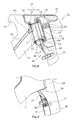
- the bicycle fork according to the invention has two brake levers 58 ( Fig. 3 ), which are arranged within the fork legs 26 and the fork crown 24.
- the two brake levers are pivotally held by pivot axes 60, wherein the pivot axes 60 are also disposed within the fork legs 26 and the fork crown 24. If the two free brake lever ends 62 from the in Fig. 3 shown position in which no braking is pressed apart for braking, a movement of the two brake shoes 56 takes place inwardly in the direction of the rim, not shown.
- the actuator 44 is provided around To realize this pivoting of the brake lever 58. This has a holding element 63 arranged within the fork crown.
- the holding element 63 carries two pivot axes 64, about the two each disposed within the holding element, in Fig. 3 dashed swivel lever 66 are pivotable.
- the pivot lever 66 are connected to the brake cable 48.
- the brake cable 48 in Fig. 3 By pulling the brake cable 48 in Fig. 3 to the top, there is thus a pivoting of the two pivot lever 66 to the outside.
- the free ends 62 of the brake lever 58 are pressed outwards, which in turn causes a movement of the two brake shoes inwardly in the direction of the rims.
- the substantially trapezoidal in plan view holding element 63 has two obliquely arranged side surfaces 68, against which the free ends 62 of the brake lever 58, when the brake is not actuated.
Abstract
Description
Die Erfindung betrifft eine Fahrradgabel mit Bremseinheit, insbesondere für Rennräder, besonders bevorzugt für Zeitfahrmaschinen.The invention relates to a bicycle fork with brake unit, in particular for road bikes, particularly preferably for time trial machines.
Bei Rennrädern und insbesondere bei Zeitfahrmaschinen spielt die Aerodynamik eine wichtige Rolle. Fahrradhersteller sind daher bestrebt, zur Verbesserung der Aerodynamik die Anordnung und Ausgestaltung der Vorderradbremse zu verändern, da eine in Fahrtrichtung vor der Fahrradgabel angeordnete Vorderradbremse zu erheblichen Luftverwirbelungen führt und somit die Aerodynamik stark beeinträchtigt. Es ist bekannt, die Vorderradbremse auf der in Fahrtrichtung Rückseite der Gabelkrone bzw. Gabelbrücke, die die beiden Gabelbeine miteinander verbindet, anzuordnen. Hierdurch kann eine gewisse Verbesserung der Aerodynamik erzielt werden, da die Vorderradbremse nicht direkt vom Fahrtwind angeströmt wird. Allerdings treten auch hierbei weiterhin erhebliche Verwirbelungen auf. Des Weiteren besteht bei derartigen Bremsenanordnungen der Nachteil, dass der Bremszug seitlich neben dem Steuerrohr des Rahmens angeordnet ist und somit ebenfalls zu einer Verschlechterung der Aerodynamik führt.In racing bikes and especially in time trial machines, aerodynamics plays an important role. Bicycle manufacturers are therefore anxious to improve the arrangement and design of the front brake to improve the aerodynamics, as arranged in the direction of travel in front of the bicycle fork front wheel brake leads to considerable air turbulence and thus greatly impaired aerodynamics. It is known to arrange the front brake on the rear in the direction of travel of the fork crown or fork bridge, which connects the two fork legs together. As a result, a certain improvement in the aerodynamics can be achieved because the front brake is not directly flowed by the wind. However, considerable turbulence also continues to occur in this case. Furthermore, in such brake assemblies has the disadvantage that the brake cable is arranged laterally next to the head tube of the frame and thus also leads to a deterioration of the aerodynamics.
Ferner werden bei Zeitfahrmaschinen sogenannte Doppelbrückengabeln verwendet. Eine derartige Gabel weist eine die beiden Gabelbeine miteinander verbindende Gabelkrone auf, wobei die Gabelkrone eine untere Lageraufnahme, wie einen Lagerzapfen, trägt. In Fahrtrichtung vor der Gabelkrone ist der Gabelschaft angeordnet. Der Gabelschaft ist somit vor dem Steuerrohr des Fahrradrahmens angeordnet. Von einem weiteren Bauteil wird das obere Steuerlager getragen. Dieses Bauteil wird vor dem Steuerrohr des Rahmens mit dem Gabelschaft verbunden und stellt ferner die Verbindung zu dem Lenker entsprechend eines Vorbaus dar. Die beiden Steuerlager sind über eine massive, eine hohe Steifigkeit aufweisende Gewindestange verbunden und gegeneinander verspannt. Durch dieses durchgehende zwischen den beiden Steuerlagern angeordnete Steuerrohr wird die erforderliche Steifigkeit realisiert.Furthermore, so-called double bridge forks are used in time trial machines. Such a fork has a fork crown interconnecting the two fork legs, wherein the fork crown a lower Bearing support, such as a journal bears. In the direction of travel in front of the fork crown of the steerer is arranged. The steerer is thus arranged in front of the head tube of the bicycle frame. From another component, the upper control bearing is worn. This component is connected in front of the head tube of the frame with the steerer tube and also provides the connection to the handlebar according to a stem. The two control bearings are connected via a solid, high rigidity threaded rod and braced against each other. Through this continuous between the two control bearings arranged control tube, the required rigidity is realized.
Aufgabe der Erfindung ist es, eine Fahrradgabel mit Bremseinheit zu schaffen, mit der die Aerodynamik verbessert werden kann.The object of the invention is to provide a bicycle fork with brake unit, with which the aerodynamics can be improved.
Die Lösung der Aufgabe erfolgt erfindungsgemäß durch die Merkmale des Anspruchs 1.The object is achieved according to the invention by the features of claim 1.
Die erfindungsgemäße Fahrradgabel mit Bremseinheit, die insbesondere für Rennräder und besonders bevorzugt für Zeitfahrmaschinen entwickelt wurde, weist zwei miteinander über eine Gabelkrone verbundene Gabelbeine auf. Die Gabelkrone ist mit einer unteren, insbesondere als Lagerzapfen ausgebildeten Lageraufnahme verbunden. Hierbei handelt es sich vorzugsweise um eine Lageraufnahme, die von unten in das Steuerrohr des Fahrradrahmens eingesteckt wird, das Steuerrohr jedoch nicht vollständig durchdringt, so dass auch keine direkte Verbindung zwischen der unteren Lageraufnahme und der oberen Lageraufnahme vorgesehen sein muss. Um die Bremseinheit erfindungsgemäß unterhalb bzw. zumindest teilweise innerhalb der Gabelkrone anordnen zu können, ist ein Aktivierungselement für die Bremse, wie ein Bowdenzug oder dergleichen durch die untere Lageraufnahme bzw. das in der Lageraufnahme angeordnete untere Lagerelement geführt. Das Aktivierungselement, bei dem es sich anstelle eines Seilzugs auch um eine Hydraulikleitung oder auch eine elektrische Leitung handeln kann, ist somit im Wesentlichen von oben zu der Bremseinheit geführt. Dies hat den Vorteil, dass auch das Aktivierungselement zumindest in diesem Bereich innerhalb des Rahmens angeordnet ist und keine Zuführung eines Bowdenzuges oder eines anderen Aktivierungselements von außen, seitlich zur Bremseinheit erforderlich ist. Hierdurch kann die Aerodynamik des Fahrrads weiter verbessert werden, da kein eine Verwirbelung hervorrufendes Aktivierungselement wie ein Bowdenzug im Luftstrom angeordnet ist. Besonders bevorzugt ist es hierbei, dass das Aktivierungselement von dem am Lenker angeordneten Bremshebel durch den Lenker, vorzugsweise unmittelbar durch den Vorbau und sodann durch, in besonders bevorzugter Ausführungsform sowohl die obere als auch die untere Lageraufnahme geführt ist. Hierbei können die beiden Lageraufnahmen mit einem insbesondere steif ausgebildeten Steuerrohr verbunden sein, wobei das Steuerrohr insbesondere die beiden in den Lageraufnahmen angeordneten Lagerelemente vorspannt.The bicycle fork according to the invention with brake unit, which was developed especially for road bikes and particularly preferred for time trial machines, has two fork legs connected to each other via a fork crown. The fork crown is connected to a lower, designed in particular as a bearing journal bearing receptacle. This is preferably a bearing receptacle which is inserted from below into the head tube of the bicycle frame, but the control tube is not completely penetrated, so that no direct connection between the lower bearing support and the upper bearing support must be provided. In order to be able to arrange the brake unit according to the invention below or at least partially within the fork crown, an activation element for the brake, such as a Bowden cable or the like, is guided through the lower bearing receptacle or the lower bearing element arranged in the bearing receptacle. The activation element, which may also be a hydraulic line or an electrical line instead of a cable pull, is thus in the Essentially guided from above to the brake unit. This has the advantage that also the activation element is arranged at least in this area within the frame and no supply of a Bowden cable or other activation element from the outside, is required laterally to the brake unit. As a result, the aerodynamics of the bicycle can be further improved because no turbulence inducing activation element such as a Bowden cable is arranged in the air flow. It is particularly preferred in this case that the activation element is guided by the handlebar arranged on the brake lever by the handlebar, preferably directly through the stem and then by, in a particularly preferred embodiment, both the upper and the lower bearing mount. Here, the two bearing receptacles may be connected to a particular stiff trained control tube, the control tube in particular biases the two arranged in the bearing mounts bearing elements.
Eine besonders bevorzugte Ausführungsform der erfindungsgemäßen Fahrradgabel weist zusätzlich einen Gabelschaft auf, der zur Gabelkrone versetzt angeordnet ist. Der Gabelschaft trägt daher vorzugsweise kein Lager und ist in montiertem Zustand, vorzugsweise in Fahrtrichtung vor dem Steuerrohr, angeordnet. Der Gabelschaft kann mit einem zusätzlichen Bauteil wie einem Vorbau verbunden werden, das sodann die obere Lageraufnahme trägt und eine Verbindung zum Lenker darstellt.A particularly preferred embodiment of the bicycle fork according to the invention additionally has a steerer, which is arranged offset to the fork crown. The fork shaft therefore preferably carries no bearing and is in the assembled state, preferably in the direction of travel in front of the head tube, arranged. The steerer tube can be connected to an additional component such as a stem, which then carries the upper bearing receptacle and connects to the handlebar.
Erfindungsgemäß ist die Bremseinheit unterhalb der Gabelkrone angeordnet. Dies ist erfindungsgemäß in besonders bevorzugter Ausführungsform möglich, da der Gabelschaft zu der Gabelkrone versetzt angeordnet ist und in montiertem Zustand in Fahrtrichtung vor dem Steuerrohr verläuft. Da der Gabelschaft vorzugsweise im Wesentlichen geradlinig nach unten verläuft und in die Gabelbeine übergeht, ist unterhalb der Gabelkrone ein Bereich geschaffen, in dem die Bremseinheit angeordnet werden kann. Durch die erfindungsgemäße Anordnung der Bremseinheit unterhalb der Gabelkrone bei einer Doppelbrückengabel kann eine Integration der Bremseinheit in die Fahrradgabel realisiert werden. Hierdurch kann gegenüber Fahrrädern, bei denen die Vorderradbremse vor oder auch hinter der Vorderradgabel angeordnet ist, die Aerodynamik erheblich verbessert werden.According to the invention, the brake unit is arranged below the fork crown. This is inventively possible in a particularly preferred embodiment, since the steerer tube is offset from the fork crown and extends in the mounted state in the direction of travel in front of the head tube. Since the steerer tube preferably extends substantially straight down and merges into the fork legs, an area is created below the fork crown, in which the brake unit can be arranged. The inventive arrangement of the brake unit below the fork crown with a double bridge fork can be an integration of the brake unit in the Bicycle fork can be realized. As a result, compared to bicycles, in which the front brake is arranged in front of or behind the front fork, the aerodynamics are significantly improved.
Wenngleich die erfindungsgemäße Anordnung des Aktivierungselements für die Bremseinheit durch die untere Lageraufnahme, insbesondere auch durch die obere Lageraufnahme in bevorzugter Ausführungsform in Kombination mit einer Doppelbrückengabel realisiert ist, ist eine derartige Anordnung des Aktivierungselements in Verbindung mit der unterhalb der Gabelkrone und gegebenenfalls in der Gabelkrone angeordneten Bremseinheit auch bei einem herkömmlichen die beiden Lagerelemente miteinander verbindenden und insbesondere verspannenden Steuerrohr möglich.Although the inventive arrangement of the activation element for the brake unit is realized by the lower bearing receptacle, in particular by the upper bearing receptacle in a preferred embodiment in combination with a double bridge fork, such an arrangement of the activation element is arranged in connection with the below the fork crown and optionally in the fork crown Brake unit even with a conventional the two bearing elements interconnecting and in particular bracing head tube possible.
Die Bremseinheit weist vorzugsweise zwei Bremshebel auf, die innerhalb der Gabelbeine und/ oder der Gabelkrone angeordnet sind. Vorzugsweise sind die Bremshebel hierbei vorzugsweise teilweise in dem oberen, in Richtung der Gabelkrone weisenden Bereich der Gabelbeine und teilweise innerhalb der Gabelkrone angeordnet. In bevorzugter Ausführungsform ragen die Bremshebel somit nicht aus der Fahrradgabel heraus, so dass eine aerodynamisch optimierte Außenfläche der Gabel realisierbar ist.The brake unit preferably has two brake levers which are arranged within the fork legs and / or the fork crown. Preferably, the brake levers are preferably arranged partially in the upper, pointing in the direction of the fork crown region of the fork legs and partially within the fork crown. In a preferred embodiment, the brake levers thus do not project out of the bicycle fork, so that an aerodynamically optimized outer surface of the fork can be realized.
Vorzugsweise handelt es sich bei den Bremshebeln um schwenkbare Bremshebel, deren Schwenkachse ebenfalls innerhalb der beiden Gabelbeine und/ oder der Gabelkrone angeordnet ist. Hierbei sind in bevorzugter Ausführungsform die beiden Schwenkhebel in einer Ebene angeordnet, so dass die beiden von den unteren Enden der Bremshebel getragenen Bremsbacken exakt einander gegenüberliegen und insbesondere die von den Bremshebeln auf die Bremsbacken übertragenen Kräfte einander gegenüberliegend in einer senkrecht zur Längsrichtung bzw. senkrecht zur Mittelebene des Vorderrads angeordneten Ebene liegen. Auch die beiden freien Bremshebelenden, d.h. diejenigen Enden der Bremshebel, die keine Bremsbacken tragen, sind in bevorzugter Ausführungsform einander gegenüberliegend angeordnet. Insbesondere kreuzen sich die beiden Bremshebel nicht.The brake levers are preferably pivotable brake levers whose pivot axis is likewise arranged within the two fork legs and / or the fork crown. Here, in a preferred embodiment, the two pivot levers are arranged in a plane so that the two brackets worn by the lower ends of the brake levers are exactly opposite each other and in particular the forces transmitted by the brake levers on the brake shoes opposite each other in a direction perpendicular to the longitudinal direction or perpendicular to Center plane of the front wheel arranged plane lie. The two free brake lever ends, ie those ends of the brake levers that do not wear brake shoes are in preferred embodiment arranged opposite each other. In particular, the two brake levers do not intersect.
Die Schwenkachsen können hierbei oberhalb der die Bremsbacken tragenden Enden angeordnet sein, so dass das Betätigen der Bremse durch Auseinanderdrücken der beiden oberen freien Enden der Bremshebel erfolgt. Ebenso ist es möglich, die Schwenkachsen unterhalb der sodann in einem Zwischenstück der Bremshebel angeordneten Bremsbacken anzuordnen, so dass das Betätigen der Bremse durch Zusammendrücken der beiden oberen freien Enden der Bremshebel erfolgt.The pivot axes may in this case be arranged above the ends bearing the brake shoes, so that the brake is actuated by pushing apart the two upper free ends of the brake levers. It is also possible to arrange the pivot axes below the then arranged in an intermediate piece of the brake lever brake shoes, so that the actuation of the brake is effected by squeezing the two upper free ends of the brake lever.
Die Betätigung der beiden Bremshebel erfolgt vorzugsweise durch eine gemeinsame Betätigungseinrichtung. Die Betätigungseinrichtung wird nachfolgend anhand einer Bremseinheit beschrieben, bei der die Schwenkachsen oberhalb der die Bremsbacken tragenden freien Enden angeordnet sind. Ein entsprechend ausgestaltetes Betätigungselement kann selbstverständlich auch bei einer Bremseinheit vorgesehen sein, bei denen die Schwenkachsen unterhalb der Bremsbacken vorgesehen sind.The actuation of the two brake levers is preferably carried out by a common actuator. The actuating device will be described below with reference to a brake unit, in which the pivot axes are arranged above the brake shoes bearing free ends. A suitably ausgestaltetes actuator can of course also be provided in a brake unit, in which the pivot axes are provided below the brake shoes.
Die Bremseinheit ist in bevorzugter Ausführungsform daher zwischen den beiden freien Bremshebelenden angeordnet. Die Betätigungseinrichtung weist vorzugsweise mindestens ein auf die Bremshebelenden einwirkendes Betätigungselement auf. Beispielsweise ist es möglich, dass die beiden Bremshebelenden schräg verlaufen bzw. aufeinander zu gerichtet sind. Zwischen den beiden Bremshebelenden kann sodann ein beispielsweise trapez- oder dreieckförmiges Betätigungselement angeordnet sein. Durch Verschieben bzw. Ziehen eines derartigen Betätigungselements nach oben werden die beiden freien Enden der Bremshebelenden auseinandergedrückt. Da diese über Schwenkachsen gehalten sind, werden die beiden Bremsbacken aufeinander zu bewegt und gegen die Felge gedrückt.The brake unit is therefore arranged in a preferred embodiment between the two free brake lever ends. The actuating device preferably has at least one actuating element acting on the brake lever ends. For example, it is possible that the two brake lever ends are inclined or directed towards each other. Then, for example, a trapezoidal or triangular actuator can be arranged between the two brake lever ends. By moving or pulling such an actuating element upwards, the two free ends of the brake lever ends are pressed apart. Since these are held by pivot axes, the two brake shoes are moved toward each other and pressed against the rim.
In besonders bevorzugter Ausführungsform der Betätigungseinrichtung weist diese zwei Betätigungselemente auf. Die beiden Betätigungselemente, die vorzugsweise über einen gemeinsamen Bremszug oder eine gemeinsame Hydraulikleitung betätigt werden, sind vorzugsweise als Schwenkhebel ausgebildet. Die Schwenkhebel, die insbesondere an einem Halteelement fixiert sind, werden, insbesondere gemeinsam, durch Betätigen des Bremszugs oder Aufbringen einer Hydraulikkraft verschwenkt. Die Schwenkhebel bringen eine Kraft auf die freien Enden der Bremshebelenden auf, wodurch diese auseinander gedrückt werden. Dies bewirkt wiederum ein Bewegen der beiden Bremsbacken aufeinander zu.In a particularly preferred embodiment of the actuating device, this has two actuation elements. The two actuating elements, which are preferably actuated via a common brake cable or a common hydraulic line, are preferably designed as pivot levers. The pivot levers, which are fixed in particular to a holding element, are pivoted, in particular jointly, by actuating the brake cable or applying a hydraulic force. The pivot levers apply a force to the free ends of the brake lever ends, thereby forcing them apart. This in turn causes a movement of the two brake shoes towards each other.
Die beiden vorzugsweise als Schwenkhebel ausgebildeten Betätigungselemente sind derart schwenkbar an einem Halteelement fixiert, dass durch Betätigen der Schwenkhebel diese in entgegengesetzte Richtung zum Bremsen nach außen verschwenkt werden. Insbesondere ist das Halteelement innerhalb der Gabelkrone angeordnet, insbesondere fixiert. In bevorzugter Weiterbildung weist das Halteelement vorzugsweise zwei als Anlageflächen für die Bremshebelenden ausgebildete Seitenflächen auf. Bei geöffneter Bremse können die Bremshebel an diesen Flächen anliegen.The two preferably designed as a pivot lever actuators are pivotally fixed to a support member that they are pivoted by operating the pivot lever in the opposite direction for braking to the outside. In particular, the holding element is arranged within the fork crown, in particular fixed. In a preferred embodiment, the retaining element preferably has two side surfaces formed as contact surfaces for the brake lever ends. When the brake is open, the brake levers can rest against these surfaces.
Erfindungsgemäß ist zur Verbesserung der Aerodynamik das Aktivierungselement wie der Bremszug oder eine entsprechende Hydraulikleitung innerhalb des Rahmens anzuordnen. Hierbei ist es bevorzugt, dass der Bremszug durch die Gabelkrone und die untere Lageraufnahme geführt ist. Von dort gelangt der Bremszug in das Steuerrohr des Rahmens und kann von hier durch die obere Lageraufnahme und das den Lenker tragende Bauteil zu dem am Lenker angeordneten Bremsgriff geführt werden. Ferner ist es bevorzugt, dass die insbesondere als Lagerzapfen ausgebildete Lageraufnahme an ihrer Oberseite verschlossen ist, so dass die Oberseite der Lageraufnahme als Zuganschlag für den Bremszug genutzt werden kann. Der Zug kann somit einschließlich Hülle durch das Steuerrohr geführt werden und mündet in den Zuganschlag. Unterhalb des Zuganschlags verläuft der Zug sodann frei, d.h. ohne Hülle, zu dem Betätigungselement der Bremseinheit.According to the invention, the activation element such as the brake cable or a corresponding hydraulic line is to be arranged within the frame to improve the aerodynamics. It is preferred that the brake cable is guided through the fork crown and the lower bearing receptacle. From there, the brake cable enters the head tube of the frame and can be guided from here through the upper bearing support and the handlebar-carrying component to the brake handle arranged on the handlebar. Furthermore, it is preferred that the bearing receptacle designed in particular as a bearing journal is closed on its upper side, so that the upper side of the bearing receptacle can be used as a pull stop for the brake cable. The train can thus be performed including casing through the head tube and opens into the cable stop. Below the Zuganschlags runs the train then free, ie without shell, to the actuating element of the brake unit.
In einer besonders bevorzugten Ausführungsform der erfindungsgemäßen Fahrradgabel mit Bremseinheit ist es möglich, diese derart auszugestalten, dass der Querschnitt des Gabelbeins in der Höhe des Reifens ein Verhältnis von Länge zu Breite von maximal 3:1 aufweist. Insofern werden mit der erfindungsgemäßen Fahrradgabel mit Bremseinheit auch die strengen Regeln des UCI, d.h. des Fahrradsportverbandes, erfüllt.In a particularly preferred embodiment of the bicycle fork with brake unit according to the invention, it is possible to design these in such a way that the cross section of the fork leg in the height of the tire has a ratio of length to width of a maximum of 3: 1. In this respect, with the bicycle fork with brake unit according to the invention, the strict rules of the UCI, i. of the cycling sport association.
Nachfolgend wird die Erfindung anhand einer bevorzugten Ausführungsform unter Bezugnahme auf die anliegenden Zeichnungen näher erläutert.The invention will be explained in more detail with reference to a preferred embodiment with reference to the accompanying drawings.
Es zeigen:
- Fig. 1
- eine schematische, teilweise geschnittene Ansicht des Fahrradrahmens im Bereich des Steuerrohrs zusammen mit der erfindungsgemäßen Fahrradgabel,
- Fig. 2
- eine schematische Seitenansicht der Fahrradgabel im Bereich der Gabelkrone, und
- Fig.3
- eine schematische, geschnittene Rückansicht der erfindungsgemäßen Fahrradgabel.
- Fig. 1
- a schematic, partially sectioned view of the bicycle frame in the region of the head tube together with the bicycle fork according to the invention,
- Fig. 2
- a schematic side view of the bicycle fork in the fork crown, and
- Figure 3
- a schematic, sectional rear view of the bicycle fork according to the invention.
Nachfolgend wird die Erfindung anhand einer Doppelbrückengabel beschrieben, wobei die erfindungsgemäße Anordnung der Bremseinheit unterhalb bzw. teilweise in der Gabelkrone mit entsprechend erfindungsgemäßer Führung des Aktivierungselements auch bei einer herkömmlichen Gabel vorgesehen sein kann, bei der die beiden Lagerelemente durch ein steifes Steuerrohr miteinander verbunden sind.The invention will be described with reference to a double bridge fork, wherein the inventive arrangement of the brake unit can be provided below or partially in the fork crown with corresponding inventive leadership of the activation element in a conventional fork, in which the two bearing elements are connected by a rigid head tube.
In
Ein oberes Bauteil 32 des Lenkkopfs weist eine ebenfalls zapfenförmige Lageraufnahme 34 zur Aufnahme des oberen Lagers 18 auf und bildet somit den Vorbau aus. Ferner weist das Bauteil 32 einen Ansatz 36 auf, der einen Fahrradlenker 38, im dargestellten Ausführungsbeispiel einen Triathlonlenker, trägt. Zwischen der Lageraufnahme 34 und dem Ansatz 36 ist ein in Richtung des Gabelschafts 28 weisender Ansatz 40 vorgesehen. Der Ansatz 40 ist über Schrauben 42 mit dem Gabelschaft 28 verbunden.An
Unterhalb der Gabelkrone 24 ist eine in die Gabelbeine 26 sowie die Gabelkrone 24 integrierte Bremseinheit 44 angeordnet. Die Bremseinheit 44 weist eine Betätigungseinrichtung 46 auf, die mit einem Bowdenzug 48 betätigbar ist. Der Bowdenzug 48 führt durch die Gabelkrone 24 und die Lageraufnahme 22 in das Innere des Steuerrohrs 16. Weiter führt der Bowdenzug 48 durch das obere Lager 18 hindurch und ist von dort zu dem Lenker 38 bzw. der Bremse geführt. Die Lageraufnahme 22 ist an der Oberseite verschlossen, so dass eine Hülse 50 des Bowdenzugs 48 nur innerhalb des Steuerrohrs angeordnet ist und bis zum Bremshebel führt. Die Hülse 50 ist in einem zylindrisch ausgebildeten Zugendanschlag 52, der vorzugsweise einstückig mit der Lageraufnahme 22 ausgebildet ist, gehalten.Below the
Die Bremseinheit 44 ist erfindungsgemäß vorzugsweise unterhalb einer Drehachse der Gabel angeordnet, wobei die Drehachse im dargestellten Ausführungsbeispiel im Wesentlichen mit der Hülse 50 innerhalb des Steuerrohrs 16 zusammen fällt.According to the invention, the
In montiertem Zustand (
Zur Justage der Bremsbacken 56 kann jeweils an der Außenseite der Gabelbeine 26 ein sich in Längsrichtung erstreckendes Langloch 27 vorgesehen sein, durch das beispielsweise mit Hilfe eines Inbusschlüssels die Bremsbacke justiert werden kann.For adjusting the
Des Weiteren ist es bevorzugt, dass an einer Innenseite der Gabelbeine 26 eine Ausbuchtung zur Aufnahme zumindest eines Teils der Bremsbacken vorgesehen ist. Hierdurch kann der Abstand der Gabelbeine verringert werden, so dass die äußeren Abmessungen der Gabel schmaler als bei herkömmlichen Gabeln sind. Dies führt zu einer weiteren Verbesserung der Aerodynamik.Furthermore, it is preferred that on an inner side of the fork legs 26 a bulge for receiving at least a portion of the brake shoes is provided. As a result, the distance between the fork legs can be reduced, so that the outer dimensions of the fork are narrower than conventional forks. This leads to a further improvement of the aerodynamics.
Die erfindungsgemäße Fahrradgabel weist zwei Bremshebel 58 (
Das im Wesentlichen in Draufsicht trapezförmige Halteelement 63 weist zwei schräg angeordnete Seitenflächen 68 auf, an denen die freien Enden 62 der Bremshebel 58 anliegen, wenn die Bremse nicht betätigt wird.The substantially trapezoidal in plan
Claims (13)
einer zwei Gabelbeine (26) miteinander verbindenden Gabelkrone (24),
einer mit der Gabelkrone (24) verbundenen unteren Lageraufnahme (22), und
einer unterhalb der Gabelkrone (24) angeordneten Bremseinheit (44),
wobei ein Aktivierungselement (50) für die Bremseinheit (44) durch die untere Lageraufnahme (22) geführt ist.Bicycle fork with brake unit, especially for racing bikes, with
a fork crown (24) interconnecting two fork legs (26),
one with the fork crown (24) connected lower bearing receptacle (22), and
a brake unit (44) arranged below the fork crown (24),
wherein an activation element (50) for the brake unit (44) is guided through the lower bearing receptacle (22).
Priority Applications (2)
| Application Number | Priority Date | Filing Date | Title |
|---|---|---|---|
| EP11175984A EP2551178A1 (en) | 2011-07-29 | 2011-07-29 | Bicycle fork with braking unit |
| US13/558,939 US20130187358A1 (en) | 2011-07-29 | 2012-07-26 | Bicycle fork with brake unit |
Applications Claiming Priority (1)
| Application Number | Priority Date | Filing Date | Title |
|---|---|---|---|
| EP11175984A EP2551178A1 (en) | 2011-07-29 | 2011-07-29 | Bicycle fork with braking unit |
Publications (1)
| Publication Number | Publication Date |
|---|---|
| EP2551178A1 true EP2551178A1 (en) | 2013-01-30 |
Family
ID=44510780
Family Applications (1)
| Application Number | Title | Priority Date | Filing Date |
|---|---|---|---|
| EP11175984A Withdrawn EP2551178A1 (en) | 2011-07-29 | 2011-07-29 | Bicycle fork with braking unit |
Country Status (2)
| Country | Link |
|---|---|
| US (1) | US20130187358A1 (en) |
| EP (1) | EP2551178A1 (en) |
Cited By (4)
| Publication number | Priority date | Publication date | Assignee | Title |
|---|---|---|---|---|
| JP2011235720A (en) * | 2010-05-10 | 2011-11-24 | ▲彦▼豪金属工業股▲ふん▼有限公司 | Rear mount brake device for reducing air resistance |
| EP2957493A1 (en) * | 2014-06-19 | 2015-12-23 | Specialized Bicycle Components, Inc. | Bicycle cable routing system |
| US9586646B2 (en) | 2015-03-20 | 2017-03-07 | Shimano Inc. | Bicycle rim brake |
| US9701293B2 (en) | 2014-06-19 | 2017-07-11 | Specialized Bicycle Components, Inc. | Bicycle cable routing system |
Families Citing this family (4)
| Publication number | Priority date | Publication date | Assignee | Title |
|---|---|---|---|---|
| US20140190775A1 (en) * | 2013-01-10 | 2014-07-10 | Felt Racing, Llc | Brake having custom kinematics and wide range adjustability for wide and narrow rims |
| US9457867B2 (en) | 2013-03-14 | 2016-10-04 | Specialized Bicycle Components, Inc. | Bicycle brake assembly |
| US10189537B2 (en) | 2015-03-24 | 2019-01-29 | Yuan-Hung WEN | Brake for bicycle |
| TWI537172B (en) * | 2015-03-24 | 2016-06-11 | 溫芫鋐 | Brake for a bicycle |
Citations (12)
| Publication number | Priority date | Publication date | Assignee | Title |
|---|---|---|---|---|
| FR736408A (en) * | 1931-09-01 | 1932-11-23 | Brake mechanism | |
| CH237541A (en) * | 1943-02-05 | 1945-04-30 | Egger Siegfried | Brake device for bicycles. |
| DE3310152A1 (en) * | 1983-03-21 | 1984-10-04 | GIRO Radsport GmbH i. Gr., 5276 Wiehl | Rim brake for bicycles, in particular racing bicycles |
| US5429381A (en) * | 1990-12-10 | 1995-07-04 | Look S.A. | Front cycle fork made of composite material |
| WO1997018122A2 (en) * | 1995-11-14 | 1997-05-22 | Nielsen Peter M | Brake assembly contained within a frame portion of a bicycle |
| EP0960807A2 (en) * | 1998-05-27 | 1999-12-01 | Shimano Inc. | Bicycle brake mounting structure |
| US6308806B1 (en) * | 1999-09-13 | 2001-10-30 | Peter M. Nielsen | Brake assembly for a cycle |
| EP1518786A1 (en) * | 2003-09-25 | 2005-03-30 | Giorgio Soglia | Bicycle brake |
| US20070052201A1 (en) * | 2005-09-06 | 2007-03-08 | Frank Hermansen | Bicycle pedal |
| EP1862385A1 (en) * | 2006-05-30 | 2007-12-05 | Shang-Ju Tsai | Bicycle structure with concealable brake |
| US20090283985A1 (en) * | 2006-09-21 | 2009-11-19 | Timothy Saul Lane | Bicycle Front Fork Assembly |
| EP2316719A1 (en) * | 2006-08-10 | 2011-05-04 | Life on the Beach Settlement, Represented by its Trustee, SG Hambros Bank and Trust (Bahamas) Limited | Fork with integrated braking system |
-
2011
- 2011-07-29 EP EP11175984A patent/EP2551178A1/en not_active Withdrawn
-
2012
- 2012-07-26 US US13/558,939 patent/US20130187358A1/en not_active Abandoned
Patent Citations (12)
| Publication number | Priority date | Publication date | Assignee | Title |
|---|---|---|---|---|
| FR736408A (en) * | 1931-09-01 | 1932-11-23 | Brake mechanism | |
| CH237541A (en) * | 1943-02-05 | 1945-04-30 | Egger Siegfried | Brake device for bicycles. |
| DE3310152A1 (en) * | 1983-03-21 | 1984-10-04 | GIRO Radsport GmbH i. Gr., 5276 Wiehl | Rim brake for bicycles, in particular racing bicycles |
| US5429381A (en) * | 1990-12-10 | 1995-07-04 | Look S.A. | Front cycle fork made of composite material |
| WO1997018122A2 (en) * | 1995-11-14 | 1997-05-22 | Nielsen Peter M | Brake assembly contained within a frame portion of a bicycle |
| EP0960807A2 (en) * | 1998-05-27 | 1999-12-01 | Shimano Inc. | Bicycle brake mounting structure |
| US6308806B1 (en) * | 1999-09-13 | 2001-10-30 | Peter M. Nielsen | Brake assembly for a cycle |
| EP1518786A1 (en) * | 2003-09-25 | 2005-03-30 | Giorgio Soglia | Bicycle brake |
| US20070052201A1 (en) * | 2005-09-06 | 2007-03-08 | Frank Hermansen | Bicycle pedal |
| EP1862385A1 (en) * | 2006-05-30 | 2007-12-05 | Shang-Ju Tsai | Bicycle structure with concealable brake |
| EP2316719A1 (en) * | 2006-08-10 | 2011-05-04 | Life on the Beach Settlement, Represented by its Trustee, SG Hambros Bank and Trust (Bahamas) Limited | Fork with integrated braking system |
| US20090283985A1 (en) * | 2006-09-21 | 2009-11-19 | Timothy Saul Lane | Bicycle Front Fork Assembly |
Cited By (6)
| Publication number | Priority date | Publication date | Assignee | Title |
|---|---|---|---|---|
| JP2011235720A (en) * | 2010-05-10 | 2011-11-24 | ▲彦▼豪金属工業股▲ふん▼有限公司 | Rear mount brake device for reducing air resistance |
| EP2957493A1 (en) * | 2014-06-19 | 2015-12-23 | Specialized Bicycle Components, Inc. | Bicycle cable routing system |
| CN105197169A (en) * | 2014-06-19 | 2015-12-30 | 专业自行车部件公司 | Bicycle cable routing system |
| US9701293B2 (en) | 2014-06-19 | 2017-07-11 | Specialized Bicycle Components, Inc. | Bicycle cable routing system |
| CN105197169B (en) * | 2014-06-19 | 2021-09-21 | 特制自行车配件有限公司 | Bicycle cable routing system |
| US9586646B2 (en) | 2015-03-20 | 2017-03-07 | Shimano Inc. | Bicycle rim brake |
Also Published As
| Publication number | Publication date |
|---|---|
| US20130187358A1 (en) | 2013-07-25 |
Similar Documents
| Publication | Publication Date | Title |
|---|---|---|
| EP2551179B1 (en) | Bicycle frame with double bridge bicycle fork | |
| EP2551178A1 (en) | Bicycle fork with braking unit | |
| DE102010010317B4 (en) | Bicycle frame with articulated linkage mounting arrangement | |
| DE102009011392B4 (en) | Bicycle control device | |
| WO2015051472A1 (en) | Two-wheeled vehicle with rear-wheel suspension | |
| DE69922581T2 (en) | Bicycle frame part with a brake mounting arrangement | |
| EP1919764A1 (en) | Racing bicycle brake and brake device for racing bicycle brakes | |
| DE202011104974U1 (en) | bicycle frame | |
| EP2409906A2 (en) | Folding bicycle | |
| EP1928723B1 (en) | Axle pivot steering device of a vehicle | |
| EP1009652A1 (en) | Bicycle frame | |
| AT520501B1 (en) | Arrangement of a frame for a bicycle and a bicycle handlebar | |
| EP2838781B1 (en) | Rotor system for a bicycle | |
| EP1352823A2 (en) | Two-wheel frame, in particular for a bicycle | |
| AT518187B1 (en) | Cable management body | |
| DE102006029781A1 (en) | Method and arrangement for fixing a shock absorber for a bicycle | |
| DE3409779A1 (en) | RIM BRAKE FOR BICYCLES | |
| DE102015009813A1 (en) | bicycle derailleur | |
| DE202017106051U1 (en) | scooter | |
| DE102017000144B3 (en) | Bicycle with arm drive | |
| DE4328758A1 (en) | Braking device, in particular for two-wheeled vehicles | |
| EP2113455B1 (en) | Bicycle with arm drive | |
| DE19961176C2 (en) | A hand-operated, combined power transmission and steering device on a bicycle or tricycle | |
| DE102010011769A1 (en) | Bicycle brake assembly | |
| DE202007017419U1 (en) | Multilane vehicle |
Legal Events
| Date | Code | Title | Description |
|---|---|---|---|
| PUAI | Public reference made under article 153(3) epc to a published international application that has entered the european phase |
Free format text: ORIGINAL CODE: 0009012 |
|
| AK | Designated contracting states |
Kind code of ref document: A1 Designated state(s): AL AT BE BG CH CY CZ DE DK EE ES FI FR GB GR HR HU IE IS IT LI LT LU LV MC MK MT NL NO PL PT RO RS SE SI SK SM TR |
|
| AX | Request for extension of the european patent |
Extension state: BA ME |
|
| STAA | Information on the status of an ep patent application or granted ep patent |
Free format text: STATUS: THE APPLICATION IS DEEMED TO BE WITHDRAWN |
|
| 18D | Application deemed to be withdrawn |
Effective date: 20130731 |