EP1928723B1 - Axle pivot steering device of a vehicle - Google Patents
Axle pivot steering device of a vehicle Download PDFInfo
- Publication number
- EP1928723B1 EP1928723B1 EP06805902A EP06805902A EP1928723B1 EP 1928723 B1 EP1928723 B1 EP 1928723B1 EP 06805902 A EP06805902 A EP 06805902A EP 06805902 A EP06805902 A EP 06805902A EP 1928723 B1 EP1928723 B1 EP 1928723B1
- Authority
- EP
- European Patent Office
- Prior art keywords
- bearing
- lever
- lever elements
- vehicle
- elements
- Prior art date
- Legal status (The legal status is an assumption and is not a legal conclusion. Google has not performed a legal analysis and makes no representation as to the accuracy of the status listed.)
- Not-in-force
Links
Images


Classifications
-
- F—MECHANICAL ENGINEERING; LIGHTING; HEATING; WEAPONS; BLASTING
- F16—ENGINEERING ELEMENTS AND UNITS; GENERAL MEASURES FOR PRODUCING AND MAINTAINING EFFECTIVE FUNCTIONING OF MACHINES OR INSTALLATIONS; THERMAL INSULATION IN GENERAL
- F16C—SHAFTS; FLEXIBLE SHAFTS; ELEMENTS OR CRANKSHAFT MECHANISMS; ROTARY BODIES OTHER THAN GEARING ELEMENTS; BEARINGS
- F16C11/00—Pivots; Pivotal connections
- F16C11/04—Pivotal connections
- F16C11/045—Pivotal connections with at least a pair of arms pivoting relatively to at least one other arm, all arms being mounted on one pin
-
- B—PERFORMING OPERATIONS; TRANSPORTING
- B62—LAND VEHICLES FOR TRAVELLING OTHERWISE THAN ON RAILS
- B62D—MOTOR VEHICLES; TRAILERS
- B62D7/00—Steering linkage; Stub axles or their mountings
- B62D7/06—Steering linkage; Stub axles or their mountings for individually-pivoted wheels, e.g. on king-pins
- B62D7/08—Steering linkage; Stub axles or their mountings for individually-pivoted wheels, e.g. on king-pins the pivotal axes being situated in a single plane transverse to the longitudinal centre line of the vehicle
- B62D7/09—Steering linkage; Stub axles or their mountings for individually-pivoted wheels, e.g. on king-pins the pivotal axes being situated in a single plane transverse to the longitudinal centre line of the vehicle characterised by means varying the ratio between the steering angles of the steered wheels
-
- B—PERFORMING OPERATIONS; TRANSPORTING
- B62—LAND VEHICLES FOR TRAVELLING OTHERWISE THAN ON RAILS
- B62D—MOTOR VEHICLES; TRAILERS
- B62D7/00—Steering linkage; Stub axles or their mountings
- B62D7/20—Links, e.g. track rods
-
- F—MECHANICAL ENGINEERING; LIGHTING; HEATING; WEAPONS; BLASTING
- F16—ENGINEERING ELEMENTS AND UNITS; GENERAL MEASURES FOR PRODUCING AND MAINTAINING EFFECTIVE FUNCTIONING OF MACHINES OR INSTALLATIONS; THERMAL INSULATION IN GENERAL
- F16C—SHAFTS; FLEXIBLE SHAFTS; ELEMENTS OR CRANKSHAFT MECHANISMS; ROTARY BODIES OTHER THAN GEARING ELEMENTS; BEARINGS
- F16C11/00—Pivots; Pivotal connections
- F16C11/02—Trunnions; Crank-pins
-
- F—MECHANICAL ENGINEERING; LIGHTING; HEATING; WEAPONS; BLASTING
- F16—ENGINEERING ELEMENTS AND UNITS; GENERAL MEASURES FOR PRODUCING AND MAINTAINING EFFECTIVE FUNCTIONING OF MACHINES OR INSTALLATIONS; THERMAL INSULATION IN GENERAL
- F16C—SHAFTS; FLEXIBLE SHAFTS; ELEMENTS OR CRANKSHAFT MECHANISMS; ROTARY BODIES OTHER THAN GEARING ELEMENTS; BEARINGS
- F16C2326/00—Articles relating to transporting
- F16C2326/20—Land vehicles
- F16C2326/24—Steering systems, e.g. steering rods or columns
Definitions
- the invention relates to a Achsschenkellenkvortechnisch a vehicle according to the closer defined in the preamble of claim 1 species, and known from EP 1 500 575 A2 ,
- the axle pivot steering is designed with a main steering cylinder device which is articulated to tie rods.
- the tie rods are in operative connection with one wheel carrier each.
- a steering kinematics of the steering knuckle is in each case in the region between the main steering cylinder device and a wheel with a lever member which is rotatable about a fixed pivot, such articulated in operative connection that in response to a position of the pivot point and a length of the lever member with a required steering angle corresponding steering angle error is essentially minimized by a reduction of the steering angle of the respective outer wheel in relation to the steering angle of the respective inner wheel.
- the present invention is therefore an object of the invention to provide a Achsschenkellenkvorraum available, which is structurally simple to manufacture and is characterized by a long life and low production costs.
- Achsschenkellenkvoriques a vehicle is executed with first lever elements, which are in each case via a second lever member with a wheel carrier in operative connection and in the region of their connections to the second lever elements via third lever elements each articulated with fixed pivot points.
- At least two of the lever elements in the connecting region of the lever elements are fork-shaped in this way and additionally each formed with bearing points spaced apart from one another and through which a bearing pin passes.
- the bearing forces resulting from the bearing forces acting on the bearing bolt are at least approximately zero, whereby an edge support in the region of a sliding bearing having connecting joint can be avoided.
- the linkage connected components or lever members of the steering knuckle assembly may be connected as compared to conventional double action ball joints Lever elements are dimensioned with smaller cross-sections, whereby a total vehicle weight is reduced in a simple manner.
- Fig. 1a shows a steerable executed vehicle axle 1 of a preferably designed as a construction vehicle vehicle in a highly schematic individual representation.
- Wheels 2A and 2B of the steerable vehicle axle 1 are convertible from the illustrated position, which corresponds to a straight-ahead driving of the vehicle, in a pivoted or in a set position for cornering of the vehicle, wherein the vehicle axle 1 in Fig. 1 b is shown as a vehicle front axle during a driver's request for a right turn.
- the wheels are 2A and 2B of the vehicle axle 1 via a Achsschenkellenkvoriques 4 from in Fig. 1 shown position in the respective requested steering angle corresponding pivoted position brought.
- the Achsschenkellenkvortechnisch 4 is presently designed with a running with a synchronizing cylinder 6A main steering cylinder device 6, which is arranged in the vehicle transverse direction parallel to a arranged between the wheels 2A, 2B arranged in a conventional manner axis 3 of the vehicle axle 1.
- a piston rod 7 of the main steering cylinder device 6 is connected at its two ends in each case via a piston rod joint 7A, 7B designed as a ball joint, each having a tie rod 8A or 8B.
- the tie rods 8A and 8B are in turn connected via arranged at their ends facing away from the piston rod 7 tie rod joints 9A, 9B with wheel carriers 10A, 10B.
- the wheel carriers 10A, 10B are fixedly connected to wheel hubs 11A, 11B of the wheels 2A and 2B, which in turn are designed to pivot together with the wheels 2A and 2B about steering pivot axes 12A, 12B relative to the axle 3.
- the tie rods 8A, 8B are made in two parts, wherein the first and second lever elements performing Sparking rods 8A_1, 8A_2 or 8B_1, 8B_2 are articulated to each other via connecting joints 8A_3 and 8B_3.
- the two third lever elements 13A and 13B are at their the connecting joints 8A_3 and 8B_3 remote from pivotally connected to the axis 3 pivot points 14A, 14B, which may be fixed on the body side, rotatably executed, so that the connecting joints 8A_3 or 8B_3 are so articulated in operative connection with the axle 3 that the third lever elements 13A and 13B respectively constitute a positive guide for the connecting joints 8A_3 and 8B_3 and the steering angle of the respective outer wheel is reduced in proportion to the steering angle of the respective inner wheel such that a steering angle error is preferably reduced to zero.
- the advantage of the invention embodied steering kinematics of the Achsschenkellenkvortechnisch 4 of the vehicle axle 1 results from the comparison according to the representations Fig. 1 and Fig. 2 ,
- the direct comparison of the two representations shows that both the angle between the second lever element 8A_2 connected to the first lever element 8A_1 and the second lever element 8B_2 and between the wheel carrier 10A and the tie rod joint 9A compared to the angles between the first lever element 8B_1 and the second lever member 8B_2 and between the wheel carrier 10B and via the tie rod joint 9B hinged thereto second lever member 8B_2 are changed such that the steering angle of the outer wheel 2A is reduced in relation to the steering angle of the inner wheel 2B relative to a known from practice vehicle to the effect in that a steering angle error between the two wheels 2A and 2B is minimized in a simple manner.
- the pivots 14A and 14B and the lengths of the third lever members 13A and 13B are provided so as to change the steering kinematics associated with the outside wheel 2A in the manner described above and minimize the steering angle error while the components of the inside wheel are changed 2B in the region of the first and second lever elements 8B_1 and 8B_2 remain almost in line, so that caused by the control of the main steering cylinder 6 steering angle of the respective inner wheel is set virtually unchanged compared to a conventionally designed steerable axle.
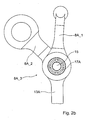
- FIG. 2a and Fig. 2b is a first embodiment of the in Fig. 1a and Fig. 1b only highly schematically illustrated connecting joint 8A_3 shown, via which the three lever elements 8A_1, 8A_2 and 13A are hinged together in the manner described above.
- first lever element or the first spur rod 8A_1 and also the second lever element or the second spur rod 8A_2 are present in the connecting region of the lever elements 8A_1, 8A_2 and 13A fork-shaped and formed in each case with spaced-apart as well as by a bearing pin 15 by intervening bearing points.
- the third lever element 13A is present in the connecting region of the lever elements 8A_1, 8A_2 and 13A at least approximately I-shaped profile and encompassed by the forked portions of the first lever member 8A_1 and the second lever member 8A_2 and rotatable about the bearing pin 15 with the two other lever elements 8A_1 and 8A_2 connected.
- the bearing pin 15 is pressed into a through hole 16 of the third lever element 13 A and thus rotatably connected thereto.
- rolling bearing devices 17A, 17B and 18A and 18B are provided both between the first lever element 8A_1 and the bearing pin 15 and between the second lever element 8A_2 and the bearing pin 15.
- connection joint 8A_3 is due to the symmetrical connection of the three lever elements 8A_1, 8A_2 and 13A to the bearing pin 15 outwardly torque-free, so that on the lever elements 8A_1, 8A_2 and 13A essentially only tensile and compressive forces must be transmitted, whereby the lever elements in comparison to Achsschenkellenkvorraumen known from the prior art, in which on the lever elements bearing moments must be supported, can be performed with lower resistance torques.
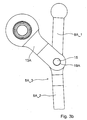
- a second embodiment of the connecting joint 8A_3 is shown, which differs from the in Fig. 2a and Fig. 2b illustrated first embodiment differs substantially only in the range of the selected types of bearings between the bearing pin 15 and the lever elements 8A_1, 8A_2 and 13A.
- the connecting joint 8A_3 of the bearing pin 15 with the first lever member 8A_1 via a press fit with this rotatably connected while between the second lever member 8A_2 and the bearing pin 15 and between the third lever member 13A and the bearing pin 15 each slide bearing means 19A, 19B and 20A, 20B are provided.
- the third lever member 13A is fork-shaped in the connecting region of the lever elements and both the forked portion of the second lever member 8A_2 and the at least approximately I-shaped profile in the connecting region of the lever elements first lever element 8A_1 surrounds.
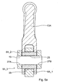
- Fig. 4a and 4b is a third embodiment of the connecting joint 8A_3 according to Fig. 1 a, which looks like the one in Fig. 5a and Fig. 5b illustrated fourth embodiment of the connecting joint 8A_3 according to Fig. 1a in comparison to the first two embodiments according to Fig. 2a and according to Fig. 3a is formed with a lower bearing height with respect to the longitudinal axis of the bearing pin 15, wherein a bearing diameter in the third embodiment and in the fourth embodiment is greater than the bearing diameter of the first two embodiments of the connecting joint 8A_3.
- the bearing pin 15 is non-rotatably connected via an interference fit with the second lever element 8A_2, which forms the outer fork of the connecting joint 8A_3.
- the third lever element 13A is rotatably supported by a rolling bearing device 21 on the bearing pin 15, wherein between the third lever member 13A and the rolling bearing device 21, a bearing sleeve 22 is arranged, on which in turn one for the first lever member 8A_1 provided further rolling bearing device 23 is arranged, via which the first lever member 8A_1 is rotatably mounted on the bearing pin 15.
- the lower bearing height of the connecting joint 8A_3 according to Fig. 4a is made possible by the fact that the spaced bearings of the forked portion of the third lever element 13A due to the reduced compared to the two first embodiments of the connecting joint 8A_3 enlarged bearing diameter pressing with smaller wall thicknesses can be performed.
- the wall thickness of the first lever element 8A_1 which is at least approximately I-shaped in the connecting region of the lever elements, is also smaller in comparison to the connecting joints according to the enlarged bearing diameter and the reduced pressure Fig. 2a and Fig. 3a reduces, so that the connecting joint 8A_3 according to Fig. 4a Total executable with the lower storage height.
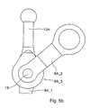
- FIG. 5a and Fig. 5b illustrated fourth embodiment of the connecting joint 8A_3 according to Fig. 1a respectively.
- Fig. 1b are the rolling bearing devices 21 and 23 of the connecting joint 8A_3 according to Fig. 4a replaced by plain bearing devices 25 and 26, which each represent a cheaper alternative compared to rolling bearing devices.
- connection joint 8A_3 corresponds to FIG Fig. 5a the structure of the connecting joint according to Fig. 4a in which the Bearing pin 15 is respectively pressed into the through holes 27A and 27B of the second lever member 8A_2, whereby between the bearing pin 15 and the second lever member 8A_2 a relative movement is avoided.
Abstract
Description
Die Erfindung betrifft eine Achsschenkellenkvorrichtung eines Fahrzeugs gemäß der im Oberbegriff des Patentanspruches 1 näher definierten Art, und bekannt aus
Aus der
Nachteilig dabei ist jedoch, dass die Verbindungsgelenke zwischen Spurteilstangen der Spurstange und den Hebelelementen als Kugelgelenke ausgeführt sind, bei welchen durch die unsymmetrisch verteilten Kraftangriffspunkte Lagermomente angreifen, die abzustützen sind. Das Abstützen der Lagermomente erfolgt über die Spurteilstangen und die Hebelelemente, weshalb diese Bauteile der Achsschenkellenkung entsprechend dimensioniert werden müssen, was jedoch eine Erhöhung des Fahrzeuggewichtes sowie der Herstellkosten der Achsschenkellenkung zur Folge hat.The disadvantage here, however, is that the connecting joints between Spark rods of the tie rod and the lever elements are designed as ball joints in which attack by the asymmetrically distributed force application points bearing moments that are to be supported. The support of the bearing moments via the Spark rods and the lever elements, which is why these components of the steering knuckle must be dimensioned accordingly, but this has an increase in the vehicle weight and the manufacturing costs of Achsschenkellenkung result.
Zusätzlich ist von Nachteil, dass die abzustützenden Lagermomente insbesondere bei Gleitlagern zu unsymmetrischen Traglastverteilungen führen, die aufgrund des daraus resultierenden so genannten Kantentragens höhere Betätigungskräfte bzw. Lenkkräfte verursachen und die Lebensdauer der Verbindungsgelenke der Achsschenkellenkung in unerwünschtem Umfang reduzieren.In addition, it is disadvantageous that the bearing torques to be supported, in particular in slide bearings, lead to asymmetrical load distributions which, due to the resulting so-called edge support, have higher actuation forces or cause steering forces and reduce the life of the steering joints of the steering knuckle to an undesirable extent.
Der vorliegenden Erfindung liegt daher die Aufgabe zugrunde, eine Achsschenkellenkvorrichtung zur Verfügung zu stellen, welche konstruktiv einfach herstellbar ist und durch eine hohe Lebensdauer und geringe Herstellkosten gekennzeichnet ist.The present invention is therefore an object of the invention to provide a Achsschenkellenkvorrichtung available, which is structurally simple to manufacture and is characterized by a long life and low production costs.
Erfindungsgemäß wird diese Aufgabe mit einer Achsschenkellenkvorrichtung eines Fahrzeugs gemäß den Merkmalen des Patentanspruches 1 gelöst.According to the invention this object is achieved with a Achsschenkellenkvorrichtung a vehicle according to the features of
Die erfindungsgemäße Achsschenkellenkvorrichtung eines Fahrzeugs ist mit ersten Hebelelementen ausgeführt, die jeweils über ein zweites Hebelelement mit einem Radträger in Wirkverbindung stehen und im Bereich ihrer Verbindungen mit den zweiten Hebelelementen über dritte Hebelelemente jeweils mit festen Drehpunkten gelenkig verbunde sind.The invention Achsschenkellenkvorrichtung a vehicle is executed with first lever elements, which are in each case via a second lever member with a wheel carrier in operative connection and in the region of their connections to the second lever elements via third lever elements each articulated with fixed pivot points.
Erfindungsgemäß sind wenigstens zwei der Hebelelemente im Verbindungsbereich der Hebelelemente derart gabelförmig ausgeführt und zusätzlich jeweils mit zueinander beabstandeten sowie von einem Lagerbolzen durchgriffenen Lagerstellen ausgebildet.According to the invention, at least two of the lever elements in the connecting region of the lever elements are fork-shaped in this way and additionally each formed with bearing points spaced apart from one another and through which a bearing pin passes.
Damit wird auf konstruktiv einfache und kostengünstige Art und Weise erreicht, dass die aus den am Lagerbolzen angreifenden Lagerkräfte resultierenden Lagermomente wenigstens annähernd Null sind, womit ein Kantentragen im Bereich eines Gleitlagerungen aufweisenden Verbindungsgelenkes vermieden werden. Zusätzlich können die über das Verbindungsgelenk verbundenen Bauteile bzw. Hebelelemente der Achsschenkellenkvorrichtung im Vergleich zu über herkömmliche, doppelt wirkende Kugelgelenke verbundene Hebelelemente mit geringeren Querschnitten dimensioniert werden, wodurch ein Fahrzeuggesamtgewicht auf einfache Art und Weise reduziert ist.This is achieved in a structurally simple and cost-effective manner, that the bearing forces resulting from the bearing forces acting on the bearing bolt are at least approximately zero, whereby an edge support in the region of a sliding bearing having connecting joint can be avoided. In addition, the linkage connected components or lever members of the steering knuckle assembly may be connected as compared to conventional double action ball joints Lever elements are dimensioned with smaller cross-sections, whereby a total vehicle weight is reduced in a simple manner.
Weitere Vorteile und vorteilhafte Weiterbildungen der Erfindung ergeben sich aus den Patentansprüchen und den unter Bezugnahme auf die Zeichnung prinzipmäßig beschriebenen Ausführungsbeispielen, wobei in der Beschreibung der verschiedenen Ausführungsbeispiele der Übersichtlichkeit halber für bau- und funktionsgleiche Bauteile dieselben Bezugszeichen verwendet werden.
Es zeigt:
- Fig. 1a
- eine Prinzipdarstellung einer Achsschenkellenkvorrichtung einer Fahrzeugachse eines Fahrzeugs, deren Lenkkinematik im Bereich zwischen einer Hauptlenkzylindereinrichtung und Radträgern mit einem Hebelelement in Wirkverbindung steht, in einem einer Geradeausfahrt äquivalenten Zustand;
- Fig. 1b
- die in
Fig. 1a dargestellte Fahrzeugachse in einem einer Kurvenfahrt äquivalenten Zustand; - Fig. 2a
- ein erstes Ausführungsbeispiel eines Verbindungsgelenkes der Achsschenkellenkvorrichtung gemäß
Fig. 1 in einer Längsschnittansicht; - Fig. 2b
- eine zweidimensionale Draufsicht auf das Verbindungsgelenk gemäß
Fig. 2a ; - Fig. 3a
- ein zweites Ausführungsbeispiel des in
Fig. 1 lediglich stark schematisiert dargestellten Verbindungsgelenkes in einer Längsschnittansicht; - Fig. 3b
- eine zweidimensionale Draufsicht auf das Verbindungsgelenk gemäß
Fig. 3a ; - Fig. 4a
- eine dreidimensionale Teilschnittansicht eines dritten Ausführungsbeispieles des Verbindungsgelenkes gemäß
Fig. 1 ; - Fig. 4b
- eine zweidimensionale Draufsicht auf das Verbindungsgelenk in
Fig. 4a ; - Fig. 5a
- eine Längsschnittansicht eines vierten Ausführungsbeispieles des Verbindungsgelenkes gemäß
Fig. 1 ; und - Fig. 5b
- eine Draufsicht auf das Verbindungsgelenk gemäß
Fig. 5a .
It shows:
- Fig. 1a
- a schematic diagram of a Achsschenkellenkvorrichtung a vehicle axle of a vehicle, the steering kinematics is in the region between a main steering cylinder device and wheel carriers in operative connection with a lever element, in a straight-ahead driving equivalent state;
- Fig. 1b
- in the
Fig. 1a illustrated vehicle axle in a cornering equivalent state; - Fig. 2a
- a first embodiment of a connecting joint of the Achsschenkellenkvorrichtung according to
Fig. 1 in a longitudinal sectional view; - Fig. 2b
- a two-dimensional plan view of the connecting joint according to
Fig. 2a ; - Fig. 3a
- a second embodiment of the in
Fig. 1 only highly schematically illustrated connecting joint in a longitudinal sectional view; - Fig. 3b
- a two-dimensional plan view of the connecting joint according to
Fig. 3a ; - Fig. 4a
- a three-dimensional partial sectional view of a third embodiment of the connecting joint according to
Fig. 1 ; - Fig. 4b
- a two-dimensional plan view of the connection joint in
Fig. 4a ; - Fig. 5a
- a longitudinal sectional view of a fourth embodiment of the connecting joint according to
Fig. 1 ; and - Fig. 5b
- a plan view of the connecting joint according to
Fig. 5a ,
Die Achsschenkellenkvorrichtung 4 ist vorliegend mit einer mit einem Gleichlaufzylinder 6A ausgeführten Hauptlenkzylindereinrichtung 6 ausgebildet, die in Fahrzeugquerrichtung parallel zu einer zwischen den Rädern 2A, 2B in an sich bekannter Art und Weise angeordneten Achse 3 der Fahrzeugachse 1 verlaufend angeordnet ist. Eine Kolbenstange 7 der Hauptlenkzylindereinrichtung 6 ist an ihren beiden Enden jeweils über ein als Kugelgelenk ausgeführtes Kolbenstangengelenk 7A, 7B mit jeweils einer Spurstange 8A bzw. 8B verbunden. Die Spurstangen 8A und 8B sind wiederum über an ihren der Kolbenstange 7 abgewandten Enden angeordnete Spurstangengelenke 9A, 9B mit Radträgern 10A, 10B verbunden. Die Radträger 10A, 10B sind fest mit Radnaben 11A, 11B der Räder 2A und 2B verbunden, die wiederum gemeinsam mit den Rädern 2A und 2B um Lenkdrehachsen 12A, 12B gegenüber der Achse 3 verschwenkbar ausgeführt sind.The
Zur Beeinflussung der von der Bewegung der Kolbenstange 7 bewirkten Schwenkbewegung der Räder 2A, 2B der Fahrzeugachse 1 sind die Abstände zwischen den Spurstangengelenken 9A, 9B und den Kolbenstangengelenken 7A, 7B verändert ausgeführt. Dazu sind die Spurstangen 8A, 8B zweiteilig ausgeführt, wobei die erste und zweite Hebelelemente darstellenden Spurteilstangen 8A_1, 8A_2 bzw. 8B_1, 8B_2 über Verbindungsgelenke 8A_3 bzw. 8B_3 gelenkig miteinander verbunden sind.In order to influence the pivoting movement of the
Zusätzlich sind die Spurstangen 8A, 8B im Bereich der Verbindungsgelenke 8A_3, 8B_3 jeweils über dritte Hebelelemente 13A, 13B gelenkig mit der Achse 3 der Fahrzeugachse 1 verbunden. Die beiden dritten Hebelelemente 13A und 13B sind an ihren den Verbindungsgelenken 8A_3 bzw. 8B_3 abgewandten Enden um mit der Achse 3 fest verbundene Drehpunkte 14A, 14B, die auch an anderer Stelle karosserieseitig festgelegt sein können, drehbar ausgeführt, so dass die Verbindungsgelenke 8A_3 bzw. 8B_3 mit der Achse 3 derart gelenkig in Wirkverbindung stehen, dass die dritten Hebelelemente 13A bzw. 13B jeweils eine Zwangsführung für die Verbindungsgelenke 8A_3 bzw. 8B_3 darstellen und der Lenkwinkeleinschlag des jeweils kurvenäußeren Rades im Verhältnis zum Lenkwinkeleinschlag des jeweils kurveninneren Rades derart verkleinert wird, dass ein Lenkwinkelfehler vorzugsweise gegen Null reduziert wird.In addition, the
Der Vorteil der erfindungsgemäß ausgeführten Lenkkinematik der Achsschenkellenkvorrichtung 4 der Fahrzeugachse 1 ergibt sich aus dem Vergleich der Darstellungen gemäß
Das bedeutet, dass die Drehpunkte 14A und 14B sowie die Längen der dritten Hebelelemente 13A und 13B derart vorgesehen sind, dass die dem kurvenäußeren Rades 2A zugeordnete Lenkkinematik in der vorbeschriebenen und einen Lenkwinkelfehler minimierenden Art und Weise verändert wird, während die Bauteile der dem kurveninneren Rad 2B zugeordneten Lenkkinematik im Bereich der ersten und zweiten Hebelelemente 8B_1 und 8B_2 nahezu auf einer Linie bleiben, so dass der durch die Ansteuerung der Hauptlenkzylindereinrichtung 6 verursachte Lenkwinkeleinschlag des jeweils kurveninneren Rades im Vergleich zu einer herkömmlich ausgeführten lenkbaren Achse nahezu unverändert eingestellt wird.That is, the
In
Dabei sind das erste Hebelelement bzw. die erste Spurteilstange 8A_1 und auch das zweite Hebelelement bzw. die zweite Spurteilstange 8A_2 vorliegend im Verbindungsbereich der Hebelelemente 8A_1, 8A_2 und 13A gabelförmig ausgeführt und jeweils mit zueinander beabstandeten sowie von einem Lagerbolzen 15 durchgriffenen Lagerstellen ausgebildet. Das dritte Hebelelement 13A ist vorliegend im Verbindungsbereich der Hebelelemente 8A_1, 8A_2 und 13A wenigstens annähernd I-profilförmig ausgebildet und von den gabelförmigen Bereichen des ersten Hebelelementes 8A_1 und des zweiten Hebelelementes 8A_2 umgriffen und über den Lagerbolzen 15 mit den beiden anderen Hebelelementen 8A_1 und 8A_2 drehbar verbunden.In this case, the first lever element or the first spur rod 8A_1 and also the second lever element or the second spur rod 8A_2 are present in the connecting region of the lever elements 8A_1, 8A_2 and 13A fork-shaped and formed in each case with spaced-apart as well as by a bearing
Der Lagerbolzen 15 ist in eine Durchgangsbohrung 16 des dritten Hebelelementes 13A eingepresst und somit drehfest mit diesem verbunden. Zusätzlich sind sowohl zwischen dem ersten Hebelelement 8A_1 und dem Lagerbolzen 15 als auch zwischen dem zweiten Hebelelement 8A_2 und dem Lagerbolzen 15 Wälzlagereinrichtungen 17A, 17B bzw. 18A und 18B vorgesehen.The bearing
Das in
In
Ein weiterer Unterschied zwischen dem ersten Ausführungsbeispiel des Verbindungsgelenkes 8A_3 gemäß
In
Bei dem dritten Ausführungsbeispiel des Verbindungsgelenkes 8A_3 gemäß
Die geringere Lagerhöhe des Verbindungsgelenkes 8A_3 gemäß
Die Reduzierung der Wandstärke der von dem Lagerbolzen 15 durchgriffenen Lagerstellen des dritten Hebelelementes 13A des Verbindungsgelenkes 8A_3 gemäß
Bei dem in
Ansonsten entspricht der Aufbau des Verbindungsgelenkes 8A_3 gemäß
Grundsätzlich besteht bei allen vorbeschriebenen vier Ausführungsbeispielen des Verbindungsgelenkes 8A_3 die Möglichkeit, die Anordnung der drei Hebelelemente 8A_1, 8A_2 und 13A in Abhängigkeit des jeweils vorliegenden Anwendungsfalles zu variieren, so dass wahlweise das erste Hebelelement 8A_1, das zweite Hebelelement 8A_2 oder das dritte Hebelelement 13A im Verbindungsbereich der Hebelelemente wenigstens annähernd I-profilförmig ausgeführt ist und von den gabelförmigen Bereichen der beiden anderen Hebelelemente 8A_2, 13A bzw. 8A_1,13A oder 8A_1 und 8A_2 in der in der Zeichnung dargestellten Art und Weise umgriffen ist.Basically, in all four embodiments of the connecting joint 8A_3 described above, it is possible to vary the arrangement of the three lever elements 8A_1, 8A_2 and 13A depending on the respective application, so that either the first lever element 8A_1, the second lever element 8A_2 or the
- 11
- Fahrzeugachsevehicle axle
- 2A, 2B2A, 2B
- Radwheel
- 33
- Achseaxis
- 44
- AchsschenkellenkungAckermann steering
- 66
- HauptlenkzylinderMain steering cylinder
- 77
- kolbenstangepiston rod
- 7A, 7B7A, 7B
- KotbenstangengetenkKotbenstangengetenk
- 8A, 8B8A, 8B
- Spurstangetie rod
- 8A_1, 8B_18A_1, 8B_1
- Spurteilstange, erstes HebelelementSpiegelstange, first lever element
- 8A_2, 8B_28A_2, 8B_2
- Spurteilstange, zweites HebelelementSpiegelstange, second lever element
- 8A_3,8B_38A_3,8B_3
- Verbindungsgelenkconnecting joint
- 9A, 9B9A, 9B
- SpurstangengelenkTie joint
- 10A, 10B10A, 10B
- Radträgerwheel carrier
- 11A, 11B11A, 11B
- Radnabe .Wheel hub.
- 12A, 12B12A, 12B
- LenkdrehachseSteering axis
- 13A, 13B13A, 13B
- drittes Hebelelementthird lever element
- 14A, 14B14A, 14B
- Drehpunktpivot point
- 1515
- Lagerbolzenbearing bolt
- 1616
- Durchgangsbohrung des dritten HebelelementesThrough hole of the third lever element
- 17A, 17B17A, 17B
- Wälzlagereinrichtungroller bearing device
- 18A, 18B18A, 18B
- Wälzlagereinrichtungroller bearing device
- 19A, 19B19A, 19B
- Gleitlagereinrichtungsliding bearing device
- 20A, 20B20A, 20B
- Gleitlagereinrichtungsliding bearing device
- 2121
- Wälzlagereinrichtungroller bearing device
- 2222
- Lagerhülsebearing sleeve
- 2323
- Wälzlagereinrichtungroller bearing device
- 24A, 24B24A, 24B
- Durchgangsbohrung des dritten HebelelementesThrough hole of the third lever element
- 2525
- Gleitlagereinrichtungsliding bearing device
- 2626
- Gleitlagereinrichtungsliding bearing device
- 27A, 27B27A, 27B
- Durchgangsbohrung des zweiten HebelelementesThrough hole of the second lever element
Claims (5)
- Axle-pivot steering device (4) of a vehicle, having first lever elements (8A_1, 8B_1) which are operatively connected in each case by means of a second lever element (8A_2, 8B_2) to a wheel carrier (10A, 10B) and, in the region of their connections to the second lever elements (8A_2, 8B_2), are articulatedly connected by means of third lever elements (13A, 13B) in each case to fixed pivot points (14A, 14B), characterized in that at least two of the lever elements (8A_1, 8A_2; 8A_1, 13A; 8A_2, 13A) are of fork-shaped design in the connecting region of the lever elements (8A_1, 8A_2, 13A), and the latter are formed in each case with bearing points which are spaced apart from one another and through which a bearing journal (15) extends, in such a way that the bearing torques resulting from the bearing forces which act on the bearing journal (15) are at least approximately zero.
- Vehicle according to Claim 1, characterized in that one of the lever elements (8A_1; 8A_2; 13A) is arranged, with its region through which the bearing journal (15) extends, at least in regions within the fork-shaped regions of the other two lever elements (8A_1, 8A_2; 8A_1, 13A; 8A_2, 13A).
- Vehicle according to Claim 1 or 2, characterized in that an interference fit is provided between the bearing journal (15) and one of the lever elements (8A_1; 8A_2; 13A).
- Vehicle according to one of Claims 1 to 3, characterized in that in each case at least one bearing device (17A, 17B, 18A, 18B; 19A, 19B, 20A, 20B; 21, 23; 25, 26), preferably a plain bearing device or a rolling bearing device, is provided between the bearing journal (15) and two of the lever elements (8A_1, 8A_2; 8A_1, 13A; 8A_2, 13A).
- Vehicle according to one of Claims 1 to 4, characterized in that a bearing sleeve (22) is provided between one of the lever elements (13A) and the bearing journal (15), which bearing sleeve (22) is rotationally fixedly connected to the lever element (13A), with a further lever element (8A_1) being rotatably mounted on the bearing sleeve (22) of the lever element (13A) which is connected thereto.
Applications Claiming Priority (2)
| Application Number | Priority Date | Filing Date | Title |
|---|---|---|---|
| DE102005046895A DE102005046895A1 (en) | 2005-09-30 | 2005-09-30 | Achsschenkellenkvorrichtung a vehicle |
| PCT/EP2006/009381 WO2007039200A1 (en) | 2005-09-30 | 2006-09-27 | Axle pivot steering device of a vehicle |
Publications (2)
| Publication Number | Publication Date |
|---|---|
| EP1928723A1 EP1928723A1 (en) | 2008-06-11 |
| EP1928723B1 true EP1928723B1 (en) | 2009-12-09 |
Family
ID=37487659
Family Applications (1)
| Application Number | Title | Priority Date | Filing Date |
|---|---|---|---|
| EP06805902A Not-in-force EP1928723B1 (en) | 2005-09-30 | 2006-09-27 | Axle pivot steering device of a vehicle |
Country Status (5)
| Country | Link |
|---|---|
| US (1) | US7617907B2 (en) |
| EP (1) | EP1928723B1 (en) |
| AT (1) | ATE451287T1 (en) |
| DE (2) | DE102005046895A1 (en) |
| WO (1) | WO2007039200A1 (en) |
Families Citing this family (7)
| Publication number | Priority date | Publication date | Assignee | Title |
|---|---|---|---|---|
| KR101029244B1 (en) * | 2010-10-11 | 2011-04-19 | 대호 (주) | Steering apparatus of tractor |
| DE102013216029A1 (en) * | 2013-08-13 | 2015-02-19 | Bayerische Motoren Werke Aktiengesellschaft | Steerable front axle for wheels of a two-lane motor vehicle and two-lane motor vehicle with such a front axle |
| DE102015203632A1 (en) * | 2015-03-02 | 2016-09-08 | Zf Friedrichshafen Ag | Independent suspension with high steering angle |
| DE102016217773A1 (en) * | 2016-09-16 | 2018-03-22 | Zf Friedrichshafen Ag | Steering device for a vehicle |
| US9821843B1 (en) | 2017-01-06 | 2017-11-21 | Robert Bosch Automotive Steering Llc | Tie rod |
| GB2591144B (en) * | 2020-01-20 | 2023-12-13 | Bamford Excavators Ltd | An axle assembly |
| CN111664165B (en) * | 2020-04-22 | 2021-10-19 | 武汉船用机械有限责任公司 | Segmented articulating device |
Family Cites Families (23)
| Publication number | Priority date | Publication date | Assignee | Title |
|---|---|---|---|---|
| US1722003A (en) * | 1927-10-10 | 1929-07-23 | Arthur W Hamby | Joint |
| DE1555295A1 (en) * | 1966-12-29 | 1972-03-09 | Ehrenreich & Cie A | Steering push rod with articulated connection to a tie rod and to a steering track lever |
| US3730653A (en) * | 1971-11-24 | 1973-05-01 | Trw Inc | Variable delivery pump |
| US4064967A (en) * | 1976-07-23 | 1977-12-27 | Clark Equipment Company | Steering mechanism |
| DE3216728C2 (en) * | 1982-05-05 | 1984-03-15 | Daimler-Benz Ag, 7000 Stuttgart | queR |
| US5094312A (en) * | 1990-12-27 | 1992-03-10 | Dana Corporation | Hydraulic cylinder for steering axle |
| DE4336286C1 (en) * | 1993-10-25 | 1995-01-26 | Daimler Benz Ag | Rack-and-pinion steering system for motor vehicles |
| IT1281790B1 (en) * | 1995-05-03 | 1998-03-03 | Carer Snc Dell Ing Angelo Gaet | FOUR-WHEEL FORKLIFT WITH NARROW TURNING RADIUS AND IMPROVED STABILITY |
| JP3711649B2 (en) | 1996-09-04 | 2005-11-02 | 株式会社豊田自動織機 | Wheel toe angle adjustment mechanism in a vehicle |
| US6073946A (en) * | 1997-07-16 | 2000-06-13 | Neway Anchorlok International, Inc. | Trailing arm suspension |
| US6357954B1 (en) * | 1997-08-15 | 2002-03-19 | Eanna Pronsias Timoney | Vehicle steering system |
| JP4342647B2 (en) * | 1999-08-20 | 2009-10-14 | 株式会社ショーワ | Back pressure groove structure of variable displacement vane pump |
| JP4601764B2 (en) * | 2000-04-18 | 2010-12-22 | 株式会社ショーワ | Variable displacement pump |
| US6719311B2 (en) * | 2001-03-01 | 2004-04-13 | Dana Corporation | Vehicle steering assembly |
| US6481731B2 (en) * | 2001-03-21 | 2002-11-19 | Delphi Technologies, Inc. | Redundant outer tie rod assembly and method |
| JP2003021077A (en) * | 2001-07-06 | 2003-01-24 | Showa Corp | Variable displacement pump |
| JP3861638B2 (en) * | 2001-08-31 | 2006-12-20 | ユニシア ジェーケーシー ステアリングシステム株式会社 | Variable displacement pump |
| US6733019B2 (en) * | 2002-05-16 | 2004-05-11 | ZF Lemförder Metallwaren AG | Two-joint arrangement |
| JP2005053471A (en) * | 2003-07-23 | 2005-03-03 | Nissan Motor Co Ltd | Steering device of vehicle |
| JP4146312B2 (en) * | 2003-07-25 | 2008-09-10 | ユニシア ジェーケーシー ステアリングシステム株式会社 | Variable displacement pump |
| DE102004053722B4 (en) | 2004-11-06 | 2020-02-20 | Zf Friedrichshafen Ag | Vehicle with at least one vehicle axle designed to be steerable via a steering knuckle |
| JP2007170321A (en) * | 2005-12-26 | 2007-07-05 | Hitachi Ltd | Variable displacement vane pump |
| JP2007216732A (en) * | 2006-02-14 | 2007-08-30 | Toyota Motor Corp | Vehicular steering device |
-
2005
- 2005-09-30 DE DE102005046895A patent/DE102005046895A1/en not_active Withdrawn
-
2006
- 2006-09-27 WO PCT/EP2006/009381 patent/WO2007039200A1/en active Application Filing
- 2006-09-27 US US12/066,280 patent/US7617907B2/en not_active Expired - Fee Related
- 2006-09-27 EP EP06805902A patent/EP1928723B1/en not_active Not-in-force
- 2006-09-27 DE DE502006005611T patent/DE502006005611D1/en active Active
- 2006-09-27 AT AT06805902T patent/ATE451287T1/en active
Also Published As
| Publication number | Publication date |
|---|---|
| DE102005046895A1 (en) | 2007-05-03 |
| WO2007039200A1 (en) | 2007-04-12 |
| US20080202843A1 (en) | 2008-08-28 |
| EP1928723A1 (en) | 2008-06-11 |
| US7617907B2 (en) | 2009-11-17 |
| ATE451287T1 (en) | 2009-12-15 |
| DE502006005611D1 (en) | 2010-01-21 |
Similar Documents
| Publication | Publication Date | Title |
|---|---|---|
| DE2825176C2 (en) | ||
| EP2396213B1 (en) | Hinge assembly for connecting two vehicle parts to a vehicle having articulated frame steering | |
| EP2285606B1 (en) | Stabilizer for a utility vehicle | |
| DE3642421C2 (en) | ||
| EP1928723B1 (en) | Axle pivot steering device of a vehicle | |
| EP2282900B1 (en) | Countersteering automotive rear axle | |
| EP2207689B1 (en) | Independent wheel suspension | |
| EP3625064B1 (en) | Wheel suspension for an at least slightly actively steerable rear wheel of a two-track vehicle, axle comprising a wheel suspension, and vehicle comprising a wheel suspension | |
| DE102009005899A1 (en) | Arrangement of a stabilizer on a suspension for motor vehicles | |
| DE102009055021A1 (en) | Multi-adjustable steering confirmation unit for a motor vehicle with a carrier and a steering column | |
| DE3331282A1 (en) | WHEEL SUSPENSION FOR STEERING FRONT WHEELS OF MOTOR VEHICLES | |
| EP3284975A1 (en) | Planetary axis | |
| DE102004053722A1 (en) | Vehicle having at least one vehicle axle steerable via a steering knuckle steering | |
| EP2435263B1 (en) | Independent vehicle suspension | |
| DE3819162A1 (en) | TORSION SPRING | |
| DE102014205990B4 (en) | Articulated connection for transmitting a steering movement to a wheel of a vehicle and steering lever | |
| DE102005057093A1 (en) | Wheel suspension assembly for a commercial vehicle | |
| DE102016207631A1 (en) | Independent suspension of a vehicle with a wheel-guiding leaf spring element made of a fiber composite material | |
| DE102015210917A1 (en) | Articulated connection and arrangement for suspension of a wheel | |
| EP0899133A2 (en) | Independent wheel suspension unit for a rear axle | |
| EP1972525B1 (en) | Automotive steering linkage | |
| DE202013101637U1 (en) | Articulated connection for transmitting a steering movement to a wheel of a vehicle | |
| WO2020221569A1 (en) | Independent wheel suspension for a two-track vehicle, axle and vehicle | |
| DE102016003885A1 (en) | Wheel suspension for a mobile crane | |
| DE102017201747B3 (en) | Independent suspension of a vehicle |
Legal Events
| Date | Code | Title | Description |
|---|---|---|---|
| PUAI | Public reference made under article 153(3) epc to a published international application that has entered the european phase |
Free format text: ORIGINAL CODE: 0009012 |
|
| 17P | Request for examination filed |
Effective date: 20080130 |
|
| AK | Designated contracting states |
Kind code of ref document: A1 Designated state(s): AT BE BG CH CY CZ DE DK EE ES FI FR GB GR HU IE IS IT LI LT LU LV MC NL PL PT RO SE SI SK TR |
|
| RIN1 | Information on inventor provided before grant (corrected) |
Inventor name: HUELSMANN, MARKUS Inventor name: KRUBER, KLAUS Inventor name: ZIEMSKI, GRZEGORZ Inventor name: MAIR, ULRICH Inventor name: WALLNER, STEFAN |
|
| GRAP | Despatch of communication of intention to grant a patent |
Free format text: ORIGINAL CODE: EPIDOSNIGR1 |
|
| GRAS | Grant fee paid |
Free format text: ORIGINAL CODE: EPIDOSNIGR3 |
|
| GRAA | (expected) grant |
Free format text: ORIGINAL CODE: 0009210 |
|
| AK | Designated contracting states |
Kind code of ref document: B1 Designated state(s): AT BE BG CH CY CZ DE DK EE ES FI FR GB GR HU IE IS IT LI LT LU LV MC NL PL PT RO SE SI SK TR |
|
| REG | Reference to a national code |
Ref country code: GB Ref legal event code: FG4D Free format text: NOT ENGLISH |
|
| REG | Reference to a national code |
Ref country code: CH Ref legal event code: EP |
|
| REG | Reference to a national code |
Ref country code: IE Ref legal event code: FG4D |
|
| REF | Corresponds to: |
Ref document number: 502006005611 Country of ref document: DE Date of ref document: 20100121 Kind code of ref document: P |
|
| REG | Reference to a national code |
Ref country code: NL Ref legal event code: VDEP Effective date: 20091209 |
|
| PG25 | Lapsed in a contracting state [announced via postgrant information from national office to epo] |
Ref country code: FI Free format text: LAPSE BECAUSE OF FAILURE TO SUBMIT A TRANSLATION OF THE DESCRIPTION OR TO PAY THE FEE WITHIN THE PRESCRIBED TIME-LIMIT Effective date: 20091209 Ref country code: SE Free format text: LAPSE BECAUSE OF FAILURE TO SUBMIT A TRANSLATION OF THE DESCRIPTION OR TO PAY THE FEE WITHIN THE PRESCRIBED TIME-LIMIT Effective date: 20091209 Ref country code: LT Free format text: LAPSE BECAUSE OF FAILURE TO SUBMIT A TRANSLATION OF THE DESCRIPTION OR TO PAY THE FEE WITHIN THE PRESCRIBED TIME-LIMIT Effective date: 20091209 |
|
| LTIE | Lt: invalidation of european patent or patent extension |
Effective date: 20091209 |
|
| PG25 | Lapsed in a contracting state [announced via postgrant information from national office to epo] |
Ref country code: SI Free format text: LAPSE BECAUSE OF FAILURE TO SUBMIT A TRANSLATION OF THE DESCRIPTION OR TO PAY THE FEE WITHIN THE PRESCRIBED TIME-LIMIT Effective date: 20091209 Ref country code: PL Free format text: LAPSE BECAUSE OF FAILURE TO SUBMIT A TRANSLATION OF THE DESCRIPTION OR TO PAY THE FEE WITHIN THE PRESCRIBED TIME-LIMIT Effective date: 20091209 Ref country code: LV Free format text: LAPSE BECAUSE OF FAILURE TO SUBMIT A TRANSLATION OF THE DESCRIPTION OR TO PAY THE FEE WITHIN THE PRESCRIBED TIME-LIMIT Effective date: 20091209 |
|
| REG | Reference to a national code |
Ref country code: IE Ref legal event code: FD4D |
|
| PG25 | Lapsed in a contracting state [announced via postgrant information from national office to epo] |
Ref country code: IE Free format text: LAPSE BECAUSE OF FAILURE TO SUBMIT A TRANSLATION OF THE DESCRIPTION OR TO PAY THE FEE WITHIN THE PRESCRIBED TIME-LIMIT Effective date: 20091209 Ref country code: ES Free format text: LAPSE BECAUSE OF FAILURE TO SUBMIT A TRANSLATION OF THE DESCRIPTION OR TO PAY THE FEE WITHIN THE PRESCRIBED TIME-LIMIT Effective date: 20100320 Ref country code: IS Free format text: LAPSE BECAUSE OF FAILURE TO SUBMIT A TRANSLATION OF THE DESCRIPTION OR TO PAY THE FEE WITHIN THE PRESCRIBED TIME-LIMIT Effective date: 20100409 Ref country code: PT Free format text: LAPSE BECAUSE OF FAILURE TO SUBMIT A TRANSLATION OF THE DESCRIPTION OR TO PAY THE FEE WITHIN THE PRESCRIBED TIME-LIMIT Effective date: 20100409 Ref country code: RO Free format text: LAPSE BECAUSE OF FAILURE TO SUBMIT A TRANSLATION OF THE DESCRIPTION OR TO PAY THE FEE WITHIN THE PRESCRIBED TIME-LIMIT Effective date: 20091209 Ref country code: NL Free format text: LAPSE BECAUSE OF FAILURE TO SUBMIT A TRANSLATION OF THE DESCRIPTION OR TO PAY THE FEE WITHIN THE PRESCRIBED TIME-LIMIT Effective date: 20091209 Ref country code: BG Free format text: LAPSE BECAUSE OF FAILURE TO SUBMIT A TRANSLATION OF THE DESCRIPTION OR TO PAY THE FEE WITHIN THE PRESCRIBED TIME-LIMIT Effective date: 20100309 Ref country code: EE Free format text: LAPSE BECAUSE OF FAILURE TO SUBMIT A TRANSLATION OF THE DESCRIPTION OR TO PAY THE FEE WITHIN THE PRESCRIBED TIME-LIMIT Effective date: 20091209 |
|
| PG25 | Lapsed in a contracting state [announced via postgrant information from national office to epo] |
Ref country code: CZ Free format text: LAPSE BECAUSE OF FAILURE TO SUBMIT A TRANSLATION OF THE DESCRIPTION OR TO PAY THE FEE WITHIN THE PRESCRIBED TIME-LIMIT Effective date: 20091209 Ref country code: SK Free format text: LAPSE BECAUSE OF FAILURE TO SUBMIT A TRANSLATION OF THE DESCRIPTION OR TO PAY THE FEE WITHIN THE PRESCRIBED TIME-LIMIT Effective date: 20091209 |
|
| PLBE | No opposition filed within time limit |
Free format text: ORIGINAL CODE: 0009261 |
|
| STAA | Information on the status of an ep patent application or granted ep patent |
Free format text: STATUS: NO OPPOSITION FILED WITHIN TIME LIMIT |
|
| PG25 | Lapsed in a contracting state [announced via postgrant information from national office to epo] |
Ref country code: GR Free format text: LAPSE BECAUSE OF FAILURE TO SUBMIT A TRANSLATION OF THE DESCRIPTION OR TO PAY THE FEE WITHIN THE PRESCRIBED TIME-LIMIT Effective date: 20100310 Ref country code: CY Free format text: LAPSE BECAUSE OF FAILURE TO SUBMIT A TRANSLATION OF THE DESCRIPTION OR TO PAY THE FEE WITHIN THE PRESCRIBED TIME-LIMIT Effective date: 20091209 |
|
| 26N | No opposition filed |
Effective date: 20100910 |
|
| PG25 | Lapsed in a contracting state [announced via postgrant information from national office to epo] |
Ref country code: DK Free format text: LAPSE BECAUSE OF FAILURE TO SUBMIT A TRANSLATION OF THE DESCRIPTION OR TO PAY THE FEE WITHIN THE PRESCRIBED TIME-LIMIT Effective date: 20091209 |
|
| BERE | Be: lapsed |
Owner name: ZF FRIEDRICHSHAFEN A.G. Effective date: 20100930 |
|
| PG25 | Lapsed in a contracting state [announced via postgrant information from national office to epo] |
Ref country code: IT Free format text: LAPSE BECAUSE OF FAILURE TO SUBMIT A TRANSLATION OF THE DESCRIPTION OR TO PAY THE FEE WITHIN THE PRESCRIBED TIME-LIMIT Effective date: 20091209 |
|
| PG25 | Lapsed in a contracting state [announced via postgrant information from national office to epo] |
Ref country code: MC Free format text: LAPSE BECAUSE OF NON-PAYMENT OF DUE FEES Effective date: 20100930 |
|
| REG | Reference to a national code |
Ref country code: CH Ref legal event code: PL |
|
| GBPC | Gb: european patent ceased through non-payment of renewal fee |
Effective date: 20100927 |
|
| REG | Reference to a national code |
Ref country code: FR Ref legal event code: ST Effective date: 20110531 |
|
| PG25 | Lapsed in a contracting state [announced via postgrant information from national office to epo] |
Ref country code: FR Free format text: LAPSE BECAUSE OF NON-PAYMENT OF DUE FEES Effective date: 20100930 Ref country code: LI Free format text: LAPSE BECAUSE OF NON-PAYMENT OF DUE FEES Effective date: 20100930 Ref country code: CH Free format text: LAPSE BECAUSE OF NON-PAYMENT OF DUE FEES Effective date: 20100930 Ref country code: BE Free format text: LAPSE BECAUSE OF NON-PAYMENT OF DUE FEES Effective date: 20100930 |
|
| PG25 | Lapsed in a contracting state [announced via postgrant information from national office to epo] |
Ref country code: GB Free format text: LAPSE BECAUSE OF NON-PAYMENT OF DUE FEES Effective date: 20100927 |
|
| PG25 | Lapsed in a contracting state [announced via postgrant information from national office to epo] |
Ref country code: HU Free format text: LAPSE BECAUSE OF FAILURE TO SUBMIT A TRANSLATION OF THE DESCRIPTION OR TO PAY THE FEE WITHIN THE PRESCRIBED TIME-LIMIT Effective date: 20100610 Ref country code: LU Free format text: LAPSE BECAUSE OF NON-PAYMENT OF DUE FEES Effective date: 20100927 |
|
| PG25 | Lapsed in a contracting state [announced via postgrant information from national office to epo] |
Ref country code: TR Free format text: LAPSE BECAUSE OF FAILURE TO SUBMIT A TRANSLATION OF THE DESCRIPTION OR TO PAY THE FEE WITHIN THE PRESCRIBED TIME-LIMIT Effective date: 20091209 |
|
| REG | Reference to a national code |
Ref country code: AT Ref legal event code: MM01 Ref document number: 451287 Country of ref document: AT Kind code of ref document: T Effective date: 20110927 |
|
| PG25 | Lapsed in a contracting state [announced via postgrant information from national office to epo] |
Ref country code: AT Free format text: LAPSE BECAUSE OF NON-PAYMENT OF DUE FEES Effective date: 20110927 |
|
| PGFP | Annual fee paid to national office [announced via postgrant information from national office to epo] |
Ref country code: DE Payment date: 20180911 Year of fee payment: 13 |
|
| REG | Reference to a national code |
Ref country code: DE Ref legal event code: R119 Ref document number: 502006005611 Country of ref document: DE |
|
| PG25 | Lapsed in a contracting state [announced via postgrant information from national office to epo] |
Ref country code: DE Free format text: LAPSE BECAUSE OF NON-PAYMENT OF DUE FEES Effective date: 20200401 |