EP3441240B1 - Reifenform und reifen - Google Patents
Reifenform und reifen Download PDFInfo
- Publication number
- EP3441240B1 EP3441240B1 EP16897968.0A EP16897968A EP3441240B1 EP 3441240 B1 EP3441240 B1 EP 3441240B1 EP 16897968 A EP16897968 A EP 16897968A EP 3441240 B1 EP3441240 B1 EP 3441240B1
- Authority
- EP
- European Patent Office
- Prior art keywords
- concave
- sipe
- convex
- range
- tire
- Prior art date
- Legal status (The legal status is an assumption and is not a legal conclusion. Google has not performed a legal analysis and makes no representation as to the accuracy of the status listed.)
- Active
Links
Images

Classifications
-
- B—PERFORMING OPERATIONS; TRANSPORTING
- B60—VEHICLES IN GENERAL
- B60C—VEHICLE TYRES; TYRE INFLATION; TYRE CHANGING; CONNECTING VALVES TO INFLATABLE ELASTIC BODIES IN GENERAL; DEVICES OR ARRANGEMENTS RELATED TO TYRES
- B60C11/00—Tyre tread bands; Tread patterns; Anti-skid inserts
- B60C11/03—Tread patterns
- B60C11/12—Tread patterns characterised by the use of narrow slits or incisions, e.g. sipes
- B60C11/1204—Tread patterns characterised by the use of narrow slits or incisions, e.g. sipes with special shape of the sipe
- B60C11/1218—Three-dimensional shape with regard to depth and extending direction
-
- B—PERFORMING OPERATIONS; TRANSPORTING
- B60—VEHICLES IN GENERAL
- B60C—VEHICLE TYRES; TYRE INFLATION; TYRE CHANGING; CONNECTING VALVES TO INFLATABLE ELASTIC BODIES IN GENERAL; DEVICES OR ARRANGEMENTS RELATED TO TYRES
- B60C11/00—Tyre tread bands; Tread patterns; Anti-skid inserts
- B60C11/03—Tread patterns
- B60C11/12—Tread patterns characterised by the use of narrow slits or incisions, e.g. sipes
- B60C11/1204—Tread patterns characterised by the use of narrow slits or incisions, e.g. sipes with special shape of the sipe
- B60C11/1222—Twisted or warped shape in the sipe plane
-
- B—PERFORMING OPERATIONS; TRANSPORTING
- B29—WORKING OF PLASTICS; WORKING OF SUBSTANCES IN A PLASTIC STATE IN GENERAL
- B29D—PRODUCING PARTICULAR ARTICLES FROM PLASTICS OR FROM SUBSTANCES IN A PLASTIC STATE
- B29D30/00—Producing pneumatic or solid tyres or parts thereof
- B29D30/06—Pneumatic tyres or parts thereof (e.g. produced by casting, moulding, compression moulding, injection moulding, centrifugal casting)
- B29D30/0601—Vulcanising tyres; Vulcanising presses for tyres
- B29D30/0606—Vulcanising moulds not integral with vulcanising presses
-
- B—PERFORMING OPERATIONS; TRANSPORTING
- B60—VEHICLES IN GENERAL
- B60C—VEHICLE TYRES; TYRE INFLATION; TYRE CHANGING; CONNECTING VALVES TO INFLATABLE ELASTIC BODIES IN GENERAL; DEVICES OR ARRANGEMENTS RELATED TO TYRES
- B60C11/00—Tyre tread bands; Tread patterns; Anti-skid inserts
- B60C11/03—Tread patterns
- B60C11/0306—Patterns comprising block rows or discontinuous ribs
-
- B—PERFORMING OPERATIONS; TRANSPORTING
- B29—WORKING OF PLASTICS; WORKING OF SUBSTANCES IN A PLASTIC STATE IN GENERAL
- B29D—PRODUCING PARTICULAR ARTICLES FROM PLASTICS OR FROM SUBSTANCES IN A PLASTIC STATE
- B29D30/00—Producing pneumatic or solid tyres or parts thereof
- B29D30/06—Pneumatic tyres or parts thereof (e.g. produced by casting, moulding, compression moulding, injection moulding, centrifugal casting)
- B29D30/0601—Vulcanising tyres; Vulcanising presses for tyres
- B29D30/0606—Vulcanising moulds not integral with vulcanising presses
- B29D2030/0607—Constructional features of the moulds
- B29D2030/0613—Means, e.g. sipes or blade-like elements, for forming narrow recesses in the tyres, e.g. cuts or incisions for winter tyres
-
- B—PERFORMING OPERATIONS; TRANSPORTING
- B60—VEHICLES IN GENERAL
- B60C—VEHICLE TYRES; TYRE INFLATION; TYRE CHANGING; CONNECTING VALVES TO INFLATABLE ELASTIC BODIES IN GENERAL; DEVICES OR ARRANGEMENTS RELATED TO TYRES
- B60C11/00—Tyre tread bands; Tread patterns; Anti-skid inserts
- B60C11/03—Tread patterns
- B60C11/11—Tread patterns in which the raised area of the pattern consists only of isolated elements, e.g. blocks
-
- B—PERFORMING OPERATIONS; TRANSPORTING
- B60—VEHICLES IN GENERAL
- B60C—VEHICLE TYRES; TYRE INFLATION; TYRE CHANGING; CONNECTING VALVES TO INFLATABLE ELASTIC BODIES IN GENERAL; DEVICES OR ARRANGEMENTS RELATED TO TYRES
- B60C11/00—Tyre tread bands; Tread patterns; Anti-skid inserts
- B60C11/03—Tread patterns
- B60C11/12—Tread patterns characterised by the use of narrow slits or incisions, e.g. sipes
- B60C11/1272—Width of the sipe
- B60C11/1281—Width of the sipe different within the same sipe, i.e. enlarged width portion at sipe bottom or along its length
-
- B—PERFORMING OPERATIONS; TRANSPORTING
- B60—VEHICLES IN GENERAL
- B60C—VEHICLE TYRES; TYRE INFLATION; TYRE CHANGING; CONNECTING VALVES TO INFLATABLE ELASTIC BODIES IN GENERAL; DEVICES OR ARRANGEMENTS RELATED TO TYRES
- B60C11/00—Tyre tread bands; Tread patterns; Anti-skid inserts
- B60C11/03—Tread patterns
- B60C11/12—Tread patterns characterised by the use of narrow slits or incisions, e.g. sipes
- B60C11/1204—Tread patterns characterised by the use of narrow slits or incisions, e.g. sipes with special shape of the sipe
- B60C2011/1209—Tread patterns characterised by the use of narrow slits or incisions, e.g. sipes with special shape of the sipe straight at the tread surface
Definitions
- Patent Literature 1 a fine concave and convex having a satin finished surface is formed on an inner wall surface of a sipe is disclosed in Patent Literature 1. Accordingly, surface tension of water entered into the sipe is relaxed so that the water in the sipe flows easily. Consequently, draining performance is improved. Attention is also drawn to the disclosures of JPH11-310012A , JP2005-262973A and EP 1782970A1 .
- a tire mold according to a first aspect of the present invention is as claimed in claim 1.
- an average width length of the concave portions may be set in a range between 0.0005 mm and 0.5 mm in the concave-convex surface view. Further, an area of the concave portion may be set in a range between 0.0000002 mm 2 and 0.2 mm 2 in the concave-convex surface view. Further, a depth of the concave portion may be set in a range between 0.0001 mm and 0.25 mm.
- a first layer extended from one end to another end in a predetermined direction of the blade is formed on a side surface of the blade.
- the first layers are formed adjacent to each other in a direction orthogonal to the predetermined direction at an interval of 0.1 mm to 0.5 mm.
- a second layer extended from one end to another end in the predetermined direction of the blade may be formed on the side surface of the blade.
- the second layers may be formed between the first layers to be adjacent to each other in a direction orthogonal to the predetermined direction at an interval of 0.035 mm to 0.165 mm.
- a tire according to a second aspect of the present invention is as claimed in claim 5.
- an average width length of the convex portions may be set in a range between 0.0005 mm and 0.5 mm in the concave-convex surface view. Further an area of the convex portion may be set in a range between 0.0000002 mm 2 and 0.2 mm 2 in the concave-convex surface view. Further, a depth of the convex portion may be set in a range between 0.0001 mm and 0.25 mm.
- rigidity of the block in which the sipe is formed can be improved.
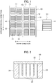
- a configuration of a tire 10 according to the present embodiment is described with reference to Fig. 1 .
- a tread pattern formed by a plurality of blocks 13 defined by a plurality of circumferential direction grooves 11 extended along a tire circumferential direction shown by an arrow A and a plurality of lateral grooves 12 crossing the circumferential direction groove 11 is formed on a tread surface of the tire 10.
- the lateral groove 12 is extended along a tire width direction shown by an arrow B.
- a plurality of sipes 14 is formed on a wheel tread portion of the block 13. Specifically, the sipe 14 is formed linearly in a tire width direction.
- the shape of the sipe 14 is not limited to a linear shape.
- the sipe 14 may be formed in a zigzag shape, a corrugated shape, or a crank shape.
- the tire mold 20 is a mold having a mold surface for vulcanizing and molding the tire 10.
- the tire mold 20 includes a block surface molding portion 22 for molding a surface of each block 13 that forms the tread pattern, a bone portion 24 for molding the circumferential direction grooves 11 and the lateral grooves 12 of the tread pattern, and a plurality of blades 26 for molding a plurality of the sipes 14.
- the blades 26 are arranged on each block surface molding portion 22 with a gap therebetween.
- a concave-convex surface is formed on a side surface of the blade 26.
- the tire 10 is manufactured by being vulcanized and molded by the tire mold 20. Further, when rubber is entered into the concave-convex surface of the blade 26, a concave-convex surface is formed on each of inner wall surfaces facing each other of the sipe 14 (hereinafter, merely referred to as an inner wall surface of the sipe 14).
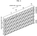
- the concave-convex surface of the blade 26 is described with reference to Fig. 3 , and Figs. 4(a) and 4(b) .
- the convex portions 30, each of which has an oval shape are continuously formed along a longitudinal direction (tire width direction) of the blade 26 shown by an arrow C, on the side surface of the blade 26. Further, the convex portions 30 are laminated along a depth direction (tire radial direction) of the blade 26 shown by an arrow D.
- the convex portion 30 is formed in an oval shape, however a shape of the convex portion 30 is not limited to an oval shape, and therefore the convex portion 30 may be formed in other shape. Further, the convex portions 30 arranged adjacent to each other may be overlapped with each other.
- the blade 26 is relatively easily manufactured by using, for example, a precision casting method using a collapsible mold formed of plaster or the like, an electroforming method (a manufacturing method of a metal product using electroplating), a diffusion bonding method (a bonding method using diffusion of atoms caused between bonded surfaces while pressurizing base materials to adhere to each other to such an extent in which plastic deformation is hardly caused at a temperature less than a melting point of the base material), or a lamination forming method.
- a precision casting method using a collapsible mold formed of plaster or the like an electroforming method (a manufacturing method of a metal product using electroplating), a diffusion bonding method (a bonding method using diffusion of atoms caused between bonded surfaces while pressurizing base materials to adhere to each other to such an extent in which plastic deformation is hardly caused at a temperature less than a melting point of the base material), or a lamination forming method.
- a longer side length of the convex portion 30 is set in a range between 0.085 mm and 0.4 mm.
- a shorter side length of the convex portion 30 is set in a range between 0.035 mm and 0.165 mm.
- the longer side length of the convex portion 30 is preferably set in a range between 0.125 mm and 0.375 mm.
- the shorter side length of the convex portion 30 is preferably set in a range between 0.05 mm and 0.15 mm.
- the longer side length of the convex portion 30 is more preferably set in a range between 0.165 mm and 0.335 mm.
- the shorter side length of the convex portion 30 is more preferably set in a range between 0.065 mm and 0.135 mm.
- the convex portions 30 are formed at an interval of 0.035 mm to 0.165 mm in the depth direction of the blade 26.
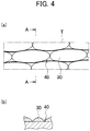
- an area of the concave portion 40 is set in a range between 0.0000002 mm 2 and 0.2 mm 2 .
- the area of the concave portion 40 is preferably set in a range between 0.00002 mm 2 and 0.1 mm 2 .
- the area of the concave portion 40 is more preferably set in a range between 0.002 mm 2 and 0.03 mm 2 .
- a depth of the concave portion 40 is set in a range between 0.0001 mm and 0.25 mm.
- the depth of the concave portion 40 is preferably set in a range between 0.0025 mm and 0.18 mm.
- the depth of the concave portion 40 is more preferably set in a range between 0.005 mm and 0.12 mm.
- a height of the convex portion 30 is set in a range between 0.0001 mm and 0.25 mm.
- the height of the convex portion 30 is preferably set in a range between 0.0025 mm and 0.18 mm.
- the height of the convex portion 30 is more preferably set in a range between 0.005 mm and 0.12 mm.
- the shape of the outline of the concave portion 40 is not a circular shape and an oval shape but a polygonal shape having many sides and having many concave-convex surfaces on the outline. Further, as shown in Fig. 4(b) , the concave portion 40 is formed in a sharp shape having a sharp distal end toward the side surface of the blade 26. In other words, the concave portion 40 is sharp in a depth direction of the concave portion 40.
- An average width length of the convex portions of the sipe 14 is set in a range between 0.0005 mm and 0.5 mm when the inner wall surface of the sipe 14 is seen from the front thereof (concave-convex surface view).
- the average width length of the convex portions of the sipe 14 is preferably set in a range between 0.005 mm and 0.35 mm.
- the average width length of the convex portions of the sipe 14 is more preferably set in a range between 0.05 mm and 0.2 mm.
- an area of the convex portion of the sipe 14 is set in a range between 0.0000002 mm 2 and 0.2 mm 2 .
- the shorter side length of the concave portion of the sipe 14 is more preferably set in a range between 0.065 mm and 0.135 mm. Further, the concave portions of the sipe 14 are formed at an interval of 0.035 mm to 0.165 mm in the depth direction of the sipe 14.
- a length of the convex portion of the sipe 14 is smaller than a length of the concave portion of the sipe 14 when the inner wall surface of the sipe 14 is seen from the front thereof.
- layers to which the first layer 50 and the second layer 60 shown in Fig. 3 are transferred are formed on the inner wall surface of the sipe 14.
- a layer to which the first layer 50 is transferred is called a first layer formed in the sipe 14.
- a layer to which the second layer 60 is transferred is called a second layer formed in the sipe 14.
- Each of the first layer and the second layer formed in the sipe 14 is extended from one end to another end of the sipe 14 in the longitudinal direction of the sipe 14.
- each shape of the first layer and the second layer formed in the sipe 14 is formed in a corrugated shape.
- the first layers formed in the sipe 14 are formed in a step-like shape so as to be adjacent to each other at an interval of 0.1 mm to 0.5 mm in the depth direction of the sipe 14.
- the first layers formed in the sipe 14 are preferably formed to be adjacent to each other at an interval of 0.15 mm to 0.45 mm.
- the first layers formed in the sipe 14 are more preferably formed to be adjacent to each other at an interval of 0.2 mm to 0.4 mm.
- arithmetic average roughness Ra of the concave-convex surface formed in the blade 26 (hereinafter, it is similarly applied to the transferred concave-convex surface in the sipe 14) is preferably set in a range between 6 ⁇ m and 20 ⁇ m.
- a friction coefficient ⁇ between rubber and rubber is largely improved. This is because rubber surfaces are meshed with each other when the arithmetic average roughness Ra is set in the range between 6 ⁇ m and 20 ⁇ m.
Landscapes
- Engineering & Computer Science (AREA)
- Mechanical Engineering (AREA)
- Tires In General (AREA)
- Moulds For Moulding Plastics Or The Like (AREA)
Claims (7)
- Reifenform (20), die Folgendes umfasst:eine Formoberfläche, die einen Reifen (10) vulkanisiert und formt, undein Blatt (26), das eine Lamelle (14) in dem Reifen (10) vulkanisiert und formt, wobei das Blatt (26) auf der Formoberfläche geformt ist,wobei:das Blatt (26) eine konkav-konvexe Oberfläche einschließt, in der eine Mehrzahl von konvexen Abschnitten (30), die aneinander angrenzend geformt sind, und eine Mehrzahl von konkaven Abschnitten (40), die zwischen den aneinander angrenzenden konvexen Abschnitten (30) geformt sind, geformt sind,eine Länge des konkaven Abschnitts (40) in einer Ansicht der konkav-konvexen Oberfläche kleiner ist als eine Länge des konvexen Abschnitts (30),der konkave Abschnitt (40) in eine Gestalt geformt ist, die in einer Tiefenrichtung des konkaven Abschnitts (40) ein spitzes distales Ende aufweist,eine erste Lage (50), die sich von einem Ende bis zu einem anderen Ende in einer vorbestimmten Richtung des Blattes (26) erstreckt, auf einer Seitenfläche des Blattes (26) geformt ist, undmehrere erste Lagen (50) aneinander angrenzend in einer Richtung, senkrecht zu der vorbestimmten Richtung, in einem Abstand von 0,1 mm bis 0,5 mm geformt sind.
- Reifenform (20) nach Anspruch 1, wobei:eine durchschnittliche Breitenlänge der konkaven Abschnitte (40) in einem Bereich zwischen 0,0005 mm und 0,5 mm in der Ansicht der konkav-konvexen Oberfläche festgesetzt ist,eine Fläche des konkaven Abschnitts (40) in einem Bereich zwischen 0,0000002 mm2 und 0,2 mm2 in der Ansicht der konkav-konvexen Oberfläche festgesetzt ist undeine Tiefe des konkaven Abschnitts (40) in einem Bereich zwischen 0,0001 mm und 0,25 mm festgesetzt ist.
- Reifenform (20) nach Anspruch 1 oder 2, wobei:eine zweite Lage (60), die sich von einem Ende bis zu einem anderen Ende in der vorbestimmten Richtung des Blattes (26) erstreckt, auf der Seitenfläche des Blattes (26) geformt ist, unddie zweiten Lagen (60) zwischen den ersten Lagen (50) so geformt sind, dass sie in einer Richtung, senkrecht zu der vorbestimmten Richtung, in einem Abstand von 0,035 mm bis 0,165 mm aneinander angrenzen.
- Reifenform (20) nach einem der Ansprüche 1 bis 3, wobei:eine längere Seitenlänge des konvexen Abschnitts (30) in einem Bereich zwischen 0,085 mm und 0,4 mm festgesetzt ist,eine kürzere Seitenlänge des konvexen Abschnitts (30) in einem Bereich zwischen 0,035 mm und 0,165 mm festgesetzt ist, unddie konvexen Abschnitte (30) in einer vorbestimmten Richtung des Blattes (26) in einem Abstand von 0,035 mm bis 0,165 mm geformt sind.
- Reifen (10), der Folgendes umfasst:eine Lauffläche,eine Mehrzahl von Umfangsrichtungsrillen (11), die auf der Lauffläche geformt sind und sich in einer Reifenumfangsrichtung erstrecken,eine Mehrzahl von seitlichen Rillen (12), die auf der Lauffläche geformt sind und sich in einer Reifenbreitenrichtung erstrecken, wobei die seitliche Rille (12) die Umfangsrichtungsrille kreuzt,einen Block (13), der in der Lauffläche geformt ist und durch eine Mehrzahl der Umfangsrichtungsrillen (11) und eine Mehrzahl der seitlichen Rillen (12) definiert wird, undeine Mehrzahl von Lamellen (14), die sich in der Reifenbreitenrichtung erstrecken und in dem Block (13) geformt sind,wobei:jede von den sich einander gegenüberliegenden inneren Wandflächen der Lamelle (14) eine konkav-konvexe Oberfläche einschließt, in der eine Mehrzahl von konkaven Abschnitten, die aneinander angrenzend geformt sind, und eine Mehrzahl von konvexen Abschnitten, die zwischen den aneinander angrenzenden konkaven Abschnitten geformt sind, geformt sind,eine Länge des konvexen Abschnitts in einer Ansicht der konkav-konvexen Oberfläche kleiner ist als eine Länge des konkaven Abschnitts,der konvexe Abschnitt in eine Gestalt geformt ist, die in einer Tiefenrichtung des konvexen Abschnitts ein spitzes distales Ende aufweist,eine Rille, die sich von einer Seite bis zu einer anderen Seite in einer vorbestimmten Richtung der Lamelle (14) erstreckt, auf jeder von den sich einander gegenüberliegenden inneren Wandflächen der Lamelle (14) geformt ist, undmehrere Rillen (50) in einer Richtung, senkrecht zu der vorbestimmten Richtung, so geformt sind, dass sie in einem Abstand von 0,1 mm bis 0,5 mm aneinander angrenzen.
- Reifen (10) nach Anspruch 5, wobei:eine durchschnittliche Breitenlänge der konvexen Abschnitte in einem Bereich zwischen 0,0005 mm und 0,5 mm in der Ansicht der konkav-konvexen Oberfläche festgesetzt ist,eine Fläche des konvexen Abschnitts in einem Bereich zwischen 0,0000002 mm2 und 0,2 mm2 in der Ansicht der konkav-konvexen Oberfläche festgesetzt ist, undeine Tiefe des konvexen Abschnitts in einem Bereich zwischen 0,0001 mm und 0,25 mm festgesetzt ist.
- Reifen (10) nach Anspruch 5 oder 6, wobei:eine längere Seitenlänge des konkaven Abschnitts in einem Bereich zwischen 0,085 mm und 0,4 mm festgesetzt ist,eine kürzere Seitenlänge des konkaven Abschnitts in einem Bereich zwischen 0,035 mm und 0,165 mm festgesetzt ist, unddie konkaven Abschnitte in einer vorbestimmten Richtung der Lamelle (14) in einem Abstand von 0,035 mm bis 0,165 mm geformt sind.
Applications Claiming Priority (2)
| Application Number | Priority Date | Filing Date | Title |
|---|---|---|---|
| JP2016076377A JP6609214B2 (ja) | 2016-04-06 | 2016-04-06 | タイヤモールド及びタイヤ |
| PCT/JP2016/084919 WO2017175416A1 (ja) | 2016-04-06 | 2016-11-25 | タイヤモールド及びタイヤ |
Publications (3)
| Publication Number | Publication Date |
|---|---|
| EP3441240A1 EP3441240A1 (de) | 2019-02-13 |
| EP3441240A4 EP3441240A4 (de) | 2019-04-03 |
| EP3441240B1 true EP3441240B1 (de) | 2020-08-26 |
Family
ID=60000989
Family Applications (1)
| Application Number | Title | Priority Date | Filing Date |
|---|---|---|---|
| EP16897968.0A Active EP3441240B1 (de) | 2016-04-06 | 2016-11-25 | Reifenform und reifen |
Country Status (5)
| Country | Link |
|---|---|
| US (1) | US20190100058A1 (de) |
| EP (1) | EP3441240B1 (de) |
| JP (1) | JP6609214B2 (de) |
| CN (1) | CN108883671B (de) |
| WO (1) | WO2017175416A1 (de) |
Families Citing this family (3)
| Publication number | Priority date | Publication date | Assignee | Title |
|---|---|---|---|---|
| CN109849393B (zh) * | 2019-02-28 | 2021-02-05 | 安徽佳通乘用子午线轮胎有限公司 | 一种标准化轮胎的制造方法 |
| JP7103306B2 (ja) * | 2019-06-04 | 2022-07-20 | 横浜ゴム株式会社 | タイヤ成形用金型 |
| JP7436803B2 (ja) * | 2020-01-17 | 2024-02-22 | 横浜ゴム株式会社 | タイヤ |
Citations (1)
| Publication number | Priority date | Publication date | Assignee | Title |
|---|---|---|---|---|
| US20020053383A1 (en) * | 1998-03-24 | 2002-05-09 | Klaus Kleinhoff | Lamella of high stability for a vulcanization mold, vulcanization mold with such lamellas, vehicle tire with tire tread in which sipes are produced by such lamellas |
Family Cites Families (9)
| Publication number | Priority date | Publication date | Assignee | Title |
|---|---|---|---|---|
| JP3811045B2 (ja) * | 2001-03-27 | 2006-08-16 | 日本碍子株式会社 | サイプブレード成形用金型及びその製造方法 |
| JP3648179B2 (ja) * | 2001-07-18 | 2005-05-18 | 住友ゴム工業株式会社 | 空気入りタイヤ及びその加硫金型 |
| JP3811052B2 (ja) * | 2001-11-13 | 2006-08-16 | 日本碍子株式会社 | タイヤ金型用サイプブレードの製造方法 |
| JP4312528B2 (ja) * | 2003-07-16 | 2009-08-12 | 横浜ゴム株式会社 | 空気入りタイヤ、タイヤ加硫モールドおよび空気入りタイヤの製造方法 |
| US7143799B2 (en) * | 2003-11-20 | 2006-12-05 | The Goodyear Tire & Rubber Company | Three-dimensional sipes for treads |
| JP2005262973A (ja) * | 2004-03-17 | 2005-09-29 | Bridgestone Corp | 空気入りタイヤ、サイプ形成用ブレード及びそのサイプ形成用ブレードを備えたタイヤ形成用金型 |
| US7793692B2 (en) * | 2005-10-31 | 2010-09-14 | The Goodyear Tire & Rubber Company | Pneumatic tire tread having sipe that devolves into groove as tread wears |
| JP5231349B2 (ja) * | 2009-07-09 | 2013-07-10 | 東洋ゴム工業株式会社 | 空気入りタイヤ |
| JP5429267B2 (ja) * | 2011-11-28 | 2014-02-26 | 横浜ゴム株式会社 | 空気入りタイヤ |
-
2016
- 2016-04-06 JP JP2016076377A patent/JP6609214B2/ja not_active Expired - Fee Related
- 2016-11-25 US US16/088,987 patent/US20190100058A1/en not_active Abandoned
- 2016-11-25 EP EP16897968.0A patent/EP3441240B1/de active Active
- 2016-11-25 CN CN201680084269.XA patent/CN108883671B/zh not_active Expired - Fee Related
- 2016-11-25 WO PCT/JP2016/084919 patent/WO2017175416A1/ja not_active Ceased
Patent Citations (1)
| Publication number | Priority date | Publication date | Assignee | Title |
|---|---|---|---|---|
| US20020053383A1 (en) * | 1998-03-24 | 2002-05-09 | Klaus Kleinhoff | Lamella of high stability for a vulcanization mold, vulcanization mold with such lamellas, vehicle tire with tire tread in which sipes are produced by such lamellas |
Also Published As
| Publication number | Publication date |
|---|---|
| JP2017185901A (ja) | 2017-10-12 |
| EP3441240A4 (de) | 2019-04-03 |
| US20190100058A1 (en) | 2019-04-04 |
| WO2017175416A1 (ja) | 2017-10-12 |
| EP3441240A1 (de) | 2019-02-13 |
| CN108883671A (zh) | 2018-11-23 |
| JP6609214B2 (ja) | 2019-11-20 |
| CN108883671B (zh) | 2020-09-18 |
Similar Documents
| Publication | Publication Date | Title |
|---|---|---|
| CN101022965B (zh) | 充气轮胎及其制造方法 | |
| CN105730152B (zh) | 充气轮胎及其成型模 | |
| EP3200987B1 (de) | Versteifungen für formgebungselemente zum formen von feineinschnitten | |
| EP2450200B1 (de) | Luftreifen | |
| CN101687444B (zh) | 包括分段刀槽花纹的轮胎 | |
| EP3441240B1 (de) | Reifenform und reifen | |
| JP2021062547A (ja) | タイヤの加硫金型及びタイヤの製造方法 | |
| US9193217B2 (en) | Pneumatic tire | |
| JP4219178B2 (ja) | 空気入りタイヤ及びその製造方法 | |
| JPH08175115A (ja) | 空気入りタイヤ | |
| JP2005505456A (ja) | 切り込みを備えたトレッド、およびこれらの切り込みを成形する層板 | |
| JP6472022B2 (ja) | 空気入りタイヤ及びその成形型 | |
| JPH0994828A (ja) | 加硫成形モールド及びこれを用いて製造された空気入 りタイヤ | |
| JP4905654B2 (ja) | 空気入りタイヤ | |
| JPH1142913A (ja) | 空気入りタイヤ及びその成形金型 | |
| CN105307844B (zh) | 用于模制和硫化轮胎胎面的包括切割构件的模制元件 | |
| CN111065529A (zh) | 用于包括隐藏通道的轮胎胎面的模具 | |
| JPH0596654A (ja) | 更生タイヤ用プレキユアトレツド、その製造方法及びこれを用いた更生タイヤ | |
| JP7081177B2 (ja) | タイヤ用モールド | |
| JP4270374B2 (ja) | 空気入りタイヤ及びタイヤ用モールド | |
| WO2017210185A1 (en) | Tire treads with improved sipes and methods of forming the same | |
| JP4940710B2 (ja) | 空気入りタイヤ | |
| JP6801432B2 (ja) | タイヤ製造用モールド | |
| JPH1095209A (ja) | 重荷重用空気入りタイヤ | |
| JPH02200406A (ja) | タイヤ加硫用金型 |
Legal Events
| Date | Code | Title | Description |
|---|---|---|---|
| STAA | Information on the status of an ep patent application or granted ep patent |
Free format text: STATUS: THE INTERNATIONAL PUBLICATION HAS BEEN MADE |
|
| PUAI | Public reference made under article 153(3) epc to a published international application that has entered the european phase |
Free format text: ORIGINAL CODE: 0009012 |
|
| STAA | Information on the status of an ep patent application or granted ep patent |
Free format text: STATUS: REQUEST FOR EXAMINATION WAS MADE |
|
| 17P | Request for examination filed |
Effective date: 20181030 |
|
| AK | Designated contracting states |
Kind code of ref document: A1 Designated state(s): AL AT BE BG CH CY CZ DE DK EE ES FI FR GB GR HR HU IE IS IT LI LT LU LV MC MK MT NL NO PL PT RO RS SE SI SK SM TR |
|
| AX | Request for extension of the european patent |
Extension state: BA ME |
|
| A4 | Supplementary search report drawn up and despatched |
Effective date: 20190228 |
|
| RIC1 | Information provided on ipc code assigned before grant |
Ipc: B60C 11/12 20060101ALI20190222BHEP Ipc: B60C 11/11 20060101ALN20190222BHEP Ipc: B29D 30/06 20060101AFI20190222BHEP |
|
| DAV | Request for validation of the european patent (deleted) | ||
| DAX | Request for extension of the european patent (deleted) | ||
| STAA | Information on the status of an ep patent application or granted ep patent |
Free format text: STATUS: EXAMINATION IS IN PROGRESS |
|
| 17Q | First examination report despatched |
Effective date: 20191111 |
|
| REG | Reference to a national code |
Ref country code: DE Ref legal event code: R079 Ref document number: 602016043002 Country of ref document: DE Free format text: PREVIOUS MAIN CLASS: B60C0011120000 Ipc: B29D0030060000 |
|
| RIC1 | Information provided on ipc code assigned before grant |
Ipc: B29D 30/06 20060101AFI20200116BHEP Ipc: B60C 11/11 20060101ALN20200116BHEP Ipc: B60C 11/12 20060101ALI20200116BHEP |
|
| GRAP | Despatch of communication of intention to grant a patent |
Free format text: ORIGINAL CODE: EPIDOSNIGR1 |
|
| STAA | Information on the status of an ep patent application or granted ep patent |
Free format text: STATUS: GRANT OF PATENT IS INTENDED |
|
| INTG | Intention to grant announced |
Effective date: 20200312 |
|
| GRAS | Grant fee paid |
Free format text: ORIGINAL CODE: EPIDOSNIGR3 |
|
| GRAA | (expected) grant |
Free format text: ORIGINAL CODE: 0009210 |
|
| STAA | Information on the status of an ep patent application or granted ep patent |
Free format text: STATUS: THE PATENT HAS BEEN GRANTED |
|
| AK | Designated contracting states |
Kind code of ref document: B1 Designated state(s): AL AT BE BG CH CY CZ DE DK EE ES FI FR GB GR HR HU IE IS IT LI LT LU LV MC MK MT NL NO PL PT RO RS SE SI SK SM TR |
|
| REG | Reference to a national code |
Ref country code: GB Ref legal event code: FG4D |
|
| REG | Reference to a national code |
Ref country code: CH Ref legal event code: EP |
|
| REG | Reference to a national code |
Ref country code: AT Ref legal event code: REF Ref document number: 1305975 Country of ref document: AT Kind code of ref document: T Effective date: 20200915 |
|
| REG | Reference to a national code |
Ref country code: IE Ref legal event code: FG4D |
|
| REG | Reference to a national code |
Ref country code: DE Ref legal event code: R096 Ref document number: 602016043002 Country of ref document: DE |
|
| REG | Reference to a national code |
Ref country code: LT Ref legal event code: MG4D |
|
| PG25 | Lapsed in a contracting state [announced via postgrant information from national office to epo] |
Ref country code: NO Free format text: LAPSE BECAUSE OF FAILURE TO SUBMIT A TRANSLATION OF THE DESCRIPTION OR TO PAY THE FEE WITHIN THE PRESCRIBED TIME-LIMIT Effective date: 20201126 Ref country code: GR Free format text: LAPSE BECAUSE OF FAILURE TO SUBMIT A TRANSLATION OF THE DESCRIPTION OR TO PAY THE FEE WITHIN THE PRESCRIBED TIME-LIMIT Effective date: 20201127 Ref country code: BG Free format text: LAPSE BECAUSE OF FAILURE TO SUBMIT A TRANSLATION OF THE DESCRIPTION OR TO PAY THE FEE WITHIN THE PRESCRIBED TIME-LIMIT Effective date: 20201126 Ref country code: SE Free format text: LAPSE BECAUSE OF FAILURE TO SUBMIT A TRANSLATION OF THE DESCRIPTION OR TO PAY THE FEE WITHIN THE PRESCRIBED TIME-LIMIT Effective date: 20200826 Ref country code: PT Free format text: LAPSE BECAUSE OF FAILURE TO SUBMIT A TRANSLATION OF THE DESCRIPTION OR TO PAY THE FEE WITHIN THE PRESCRIBED TIME-LIMIT Effective date: 20201228 Ref country code: HR Free format text: LAPSE BECAUSE OF FAILURE TO SUBMIT A TRANSLATION OF THE DESCRIPTION OR TO PAY THE FEE WITHIN THE PRESCRIBED TIME-LIMIT Effective date: 20200826 Ref country code: FI Free format text: LAPSE BECAUSE OF FAILURE TO SUBMIT A TRANSLATION OF THE DESCRIPTION OR TO PAY THE FEE WITHIN THE PRESCRIBED TIME-LIMIT Effective date: 20200826 Ref country code: LT Free format text: LAPSE BECAUSE OF FAILURE TO SUBMIT A TRANSLATION OF THE DESCRIPTION OR TO PAY THE FEE WITHIN THE PRESCRIBED TIME-LIMIT Effective date: 20200826 |
|
| REG | Reference to a national code |
Ref country code: NL Ref legal event code: MP Effective date: 20200826 |
|
| REG | Reference to a national code |
Ref country code: AT Ref legal event code: MK05 Ref document number: 1305975 Country of ref document: AT Kind code of ref document: T Effective date: 20200826 |
|
| PG25 | Lapsed in a contracting state [announced via postgrant information from national office to epo] |
Ref country code: LV Free format text: LAPSE BECAUSE OF FAILURE TO SUBMIT A TRANSLATION OF THE DESCRIPTION OR TO PAY THE FEE WITHIN THE PRESCRIBED TIME-LIMIT Effective date: 20200826 Ref country code: NL Free format text: LAPSE BECAUSE OF FAILURE TO SUBMIT A TRANSLATION OF THE DESCRIPTION OR TO PAY THE FEE WITHIN THE PRESCRIBED TIME-LIMIT Effective date: 20200826 Ref country code: PL Free format text: LAPSE BECAUSE OF FAILURE TO SUBMIT A TRANSLATION OF THE DESCRIPTION OR TO PAY THE FEE WITHIN THE PRESCRIBED TIME-LIMIT Effective date: 20200826 Ref country code: RS Free format text: LAPSE BECAUSE OF FAILURE TO SUBMIT A TRANSLATION OF THE DESCRIPTION OR TO PAY THE FEE WITHIN THE PRESCRIBED TIME-LIMIT Effective date: 20200826 Ref country code: IS Free format text: LAPSE BECAUSE OF FAILURE TO SUBMIT A TRANSLATION OF THE DESCRIPTION OR TO PAY THE FEE WITHIN THE PRESCRIBED TIME-LIMIT Effective date: 20201226 |
|
| PG25 | Lapsed in a contracting state [announced via postgrant information from national office to epo] |
Ref country code: DK Free format text: LAPSE BECAUSE OF FAILURE TO SUBMIT A TRANSLATION OF THE DESCRIPTION OR TO PAY THE FEE WITHIN THE PRESCRIBED TIME-LIMIT Effective date: 20200826 Ref country code: CZ Free format text: LAPSE BECAUSE OF FAILURE TO SUBMIT A TRANSLATION OF THE DESCRIPTION OR TO PAY THE FEE WITHIN THE PRESCRIBED TIME-LIMIT Effective date: 20200826 Ref country code: RO Free format text: LAPSE BECAUSE OF FAILURE TO SUBMIT A TRANSLATION OF THE DESCRIPTION OR TO PAY THE FEE WITHIN THE PRESCRIBED TIME-LIMIT Effective date: 20200826 Ref country code: EE Free format text: LAPSE BECAUSE OF FAILURE TO SUBMIT A TRANSLATION OF THE DESCRIPTION OR TO PAY THE FEE WITHIN THE PRESCRIBED TIME-LIMIT Effective date: 20200826 Ref country code: SM Free format text: LAPSE BECAUSE OF FAILURE TO SUBMIT A TRANSLATION OF THE DESCRIPTION OR TO PAY THE FEE WITHIN THE PRESCRIBED TIME-LIMIT Effective date: 20200826 |
|
| REG | Reference to a national code |
Ref country code: DE Ref legal event code: R097 Ref document number: 602016043002 Country of ref document: DE |
|
| PG25 | Lapsed in a contracting state [announced via postgrant information from national office to epo] |
Ref country code: AT Free format text: LAPSE BECAUSE OF FAILURE TO SUBMIT A TRANSLATION OF THE DESCRIPTION OR TO PAY THE FEE WITHIN THE PRESCRIBED TIME-LIMIT Effective date: 20200826 Ref country code: AL Free format text: LAPSE BECAUSE OF FAILURE TO SUBMIT A TRANSLATION OF THE DESCRIPTION OR TO PAY THE FEE WITHIN THE PRESCRIBED TIME-LIMIT Effective date: 20200826 Ref country code: ES Free format text: LAPSE BECAUSE OF FAILURE TO SUBMIT A TRANSLATION OF THE DESCRIPTION OR TO PAY THE FEE WITHIN THE PRESCRIBED TIME-LIMIT Effective date: 20200826 |
|
| PG25 | Lapsed in a contracting state [announced via postgrant information from national office to epo] |
Ref country code: MC Free format text: LAPSE BECAUSE OF FAILURE TO SUBMIT A TRANSLATION OF THE DESCRIPTION OR TO PAY THE FEE WITHIN THE PRESCRIBED TIME-LIMIT Effective date: 20200826 Ref country code: SK Free format text: LAPSE BECAUSE OF FAILURE TO SUBMIT A TRANSLATION OF THE DESCRIPTION OR TO PAY THE FEE WITHIN THE PRESCRIBED TIME-LIMIT Effective date: 20200826 |
|
| REG | Reference to a national code |
Ref country code: CH Ref legal event code: PL |
|
| PLBE | No opposition filed within time limit |
Free format text: ORIGINAL CODE: 0009261 |
|
| STAA | Information on the status of an ep patent application or granted ep patent |
Free format text: STATUS: NO OPPOSITION FILED WITHIN TIME LIMIT |
|
| GBPC | Gb: european patent ceased through non-payment of renewal fee |
Effective date: 20201126 |
|
| PG25 | Lapsed in a contracting state [announced via postgrant information from national office to epo] |
Ref country code: IT Free format text: LAPSE BECAUSE OF FAILURE TO SUBMIT A TRANSLATION OF THE DESCRIPTION OR TO PAY THE FEE WITHIN THE PRESCRIBED TIME-LIMIT Effective date: 20200826 Ref country code: LU Free format text: LAPSE BECAUSE OF NON-PAYMENT OF DUE FEES Effective date: 20201125 |
|
| 26N | No opposition filed |
Effective date: 20210527 |
|
| REG | Reference to a national code |
Ref country code: BE Ref legal event code: MM Effective date: 20201130 |
|
| PG25 | Lapsed in a contracting state [announced via postgrant information from national office to epo] |
Ref country code: CH Free format text: LAPSE BECAUSE OF NON-PAYMENT OF DUE FEES Effective date: 20201130 Ref country code: SI Free format text: LAPSE BECAUSE OF FAILURE TO SUBMIT A TRANSLATION OF THE DESCRIPTION OR TO PAY THE FEE WITHIN THE PRESCRIBED TIME-LIMIT Effective date: 20200826 Ref country code: LI Free format text: LAPSE BECAUSE OF NON-PAYMENT OF DUE FEES Effective date: 20201130 |
|
| PG25 | Lapsed in a contracting state [announced via postgrant information from national office to epo] |
Ref country code: IE Free format text: LAPSE BECAUSE OF NON-PAYMENT OF DUE FEES Effective date: 20201125 |
|
| PG25 | Lapsed in a contracting state [announced via postgrant information from national office to epo] |
Ref country code: GB Free format text: LAPSE BECAUSE OF NON-PAYMENT OF DUE FEES Effective date: 20201126 |
|
| PG25 | Lapsed in a contracting state [announced via postgrant information from national office to epo] |
Ref country code: IS Free format text: LAPSE BECAUSE OF FAILURE TO SUBMIT A TRANSLATION OF THE DESCRIPTION OR TO PAY THE FEE WITHIN THE PRESCRIBED TIME-LIMIT Effective date: 20201226 Ref country code: TR Free format text: LAPSE BECAUSE OF FAILURE TO SUBMIT A TRANSLATION OF THE DESCRIPTION OR TO PAY THE FEE WITHIN THE PRESCRIBED TIME-LIMIT Effective date: 20200826 Ref country code: MT Free format text: LAPSE BECAUSE OF FAILURE TO SUBMIT A TRANSLATION OF THE DESCRIPTION OR TO PAY THE FEE WITHIN THE PRESCRIBED TIME-LIMIT Effective date: 20200826 Ref country code: CY Free format text: LAPSE BECAUSE OF FAILURE TO SUBMIT A TRANSLATION OF THE DESCRIPTION OR TO PAY THE FEE WITHIN THE PRESCRIBED TIME-LIMIT Effective date: 20200826 |
|
| PG25 | Lapsed in a contracting state [announced via postgrant information from national office to epo] |
Ref country code: MK Free format text: LAPSE BECAUSE OF FAILURE TO SUBMIT A TRANSLATION OF THE DESCRIPTION OR TO PAY THE FEE WITHIN THE PRESCRIBED TIME-LIMIT Effective date: 20200826 |
|
| PG25 | Lapsed in a contracting state [announced via postgrant information from national office to epo] |
Ref country code: BE Free format text: LAPSE BECAUSE OF NON-PAYMENT OF DUE FEES Effective date: 20201130 |
|
| P01 | Opt-out of the competence of the unified patent court (upc) registered |
Effective date: 20230531 |
|
| PGFP | Annual fee paid to national office [announced via postgrant information from national office to epo] |
Ref country code: FR Payment date: 20231120 Year of fee payment: 8 Ref country code: DE Payment date: 20231121 Year of fee payment: 8 |
|
| REG | Reference to a national code |
Ref country code: DE Ref legal event code: R119 Ref document number: 602016043002 Country of ref document: DE |
|
| PG25 | Lapsed in a contracting state [announced via postgrant information from national office to epo] |
Ref country code: DE Free format text: LAPSE BECAUSE OF NON-PAYMENT OF DUE FEES Effective date: 20250603 |
|
| PG25 | Lapsed in a contracting state [announced via postgrant information from national office to epo] |
Ref country code: FR Free format text: LAPSE BECAUSE OF NON-PAYMENT OF DUE FEES Effective date: 20241130 |