EP3441225A1 - Maschinengestell - Google Patents
Maschinengestell Download PDFInfo
- Publication number
- EP3441225A1 EP3441225A1 EP18198752.0A EP18198752A EP3441225A1 EP 3441225 A1 EP3441225 A1 EP 3441225A1 EP 18198752 A EP18198752 A EP 18198752A EP 3441225 A1 EP3441225 A1 EP 3441225A1
- Authority
- EP
- European Patent Office
- Prior art keywords
- clamping
- machine frame
- gap
- clamping element
- sleeve
- Prior art date
- Legal status (The legal status is an assumption and is not a legal conclusion. Google has not performed a legal analysis and makes no representation as to the accuracy of the status listed.)
- Granted
Links
Images


Classifications
-
- B—PERFORMING OPERATIONS; TRANSPORTING
- B41—PRINTING; LINING MACHINES; TYPEWRITERS; STAMPS
- B41F—PRINTING MACHINES OR PRESSES
- B41F17/00—Printing apparatus or machines of special types or for particular purposes, not otherwise provided for
- B41F17/001—Pad printing apparatus or machines
-
- B—PERFORMING OPERATIONS; TRANSPORTING
- B41—PRINTING; LINING MACHINES; TYPEWRITERS; STAMPS
- B41F—PRINTING MACHINES OR PRESSES
- B41F13/00—Common details of rotary presses or machines
- B41F13/0024—Frames
-
- F—MECHANICAL ENGINEERING; LIGHTING; HEATING; WEAPONS; BLASTING
- F16—ENGINEERING ELEMENTS AND UNITS; GENERAL MEASURES FOR PRODUCING AND MAINTAINING EFFECTIVE FUNCTIONING OF MACHINES OR INSTALLATIONS; THERMAL INSULATION IN GENERAL
- F16M—FRAMES, CASINGS OR BEDS OF ENGINES, MACHINES OR APPARATUS, NOT SPECIFIC TO ENGINES, MACHINES OR APPARATUS PROVIDED FOR ELSEWHERE; STANDS; SUPPORTS
- F16M7/00—Details of attaching or adjusting engine beds, frames, or supporting-legs on foundation or base; Attaching non-moving engine parts, e.g. cylinder blocks
Definitions
- the invention relates to a machine frame, wherein the machine frame comprises a plurality of rod elements and at least one, preferably plate-like formed carrier element, wherein the rod elements are connected by means of a connecting device with the support member to form the machine frame in an assembled state.
- the support element is not easily connectable to the rod elements in conventional machine frames.
- only complex connecting devices are known from the prior art, although allow a positionally accurate attachment of the support member to the rod elements, but not easy to use.
- an opening means a material-free space lying in the carrier element, which is completely made of material is enclosed by the support element. Under a recess is a material-free space in the support member to understand, which opens into a narrow side of the support member.
- the object of the present invention is to provide a machine frame in which the carrier element can be connected in a simple manner to the rod elements in order to form the machine frame in the assembled state.
- the connection should not only be easy to handle, but also allows accurate positioning of the support member on the rod elements.
- the connecting device comprises at least one clamping element, in particular in the form of a clamping screw, a clamping element and a collar element acting as a clamping sleeve in the assembled state, wherein the connecting device is arranged in the opening or recess of the carrier element, wherein the sleeve element is formed like a flange and with an outer flange a contact surface axially abuts against the support member, and wherein the sleeve member with a sleeve-forming radially inner portion surrounds the cylindrically shaped mounting portion of the rod member and clamped in the assembled state with a contact surface on the mounting portion, wherein in the radial direction between the sleeve member and one Opening or recess bounding wall of the support member a, preferably annular, gap is formed, which tapers in the axial direction to the outer flange portion of the sleeve member towards wedge-shaped,
- the gap tapers at an angle of 2 ° to 10 °, preferably 3 ° to 8 °, in particular 3.5 ° to 6 °, in particular 4 ° to 5 °, to the axial direction.
- This achieves an advantageous ratio of movement of the clamping element into the gap and clamping of the sleeve element on the other hand.
- the cuff-element-side clamping surface and the inner surface of the clamping element extend at an angle of 2 ° to 10 °, preferably 3 ° to 8 °, in particular 3.5 ° to 6 °, in particular 4 ° to 5 ° to the axial direction and thereby the rejuvenation of the gap is at least partially, in particular completely generated.
- a placement of the carrier element over the outer flange section with the contact surface can be carried out precisely, wherein the orientation and position of the support member when tightening the clamping element does not change, since the clamping element against the sleeve member and the support member but is not clamped directly against the rod member.
- the carrier element can be accurately aligned to the rod member before tightening the clamping element and then the clamping element can be tightened so that the individual parts of the machine frame firmly connected and braced, with this tightening the orientation and position of Carrier element to the rod element no longer changes, so that the machine frame is set exactly in the assembled state.
- the flange portion is formed circular disk-shaped.
- the carrier element in particular when the flange portion is arranged in a recess, advantageously applied along the entire extent of the circular disk-shaped flange portion of these and thus accurately positioned.
- a gap-defining carrier element-side clamping surface is cylindrical.
- the opening or recess are introduced in this embodiment in a simple manner in the support element, for example by means of a drill, as well as the carrier element-side clamping surface in this Embodiment is cylindrical.
- the carrier element can be manufactured in a simple manner.
- the clamping element with an outer surface which corresponds to the lateral surface of a truncated cone or a cylinder, on a concentric to the outer surface, the gap limiting, carrier element-side clamping surface is applied.
- the outer surface of the clamping element in this embodiment thus follows the course of the carrier element-side clamping surface. In this way, a sliding with low resistance of the carrier element-side clamping surface can be ensured over the outer surface of the clamping member.
- the pulling of the clamping element runs in the gap by tightening the clamping element in an advantageous and smooth manner, since a low resistance must be overcome.
- the clamping element with an inner surface which corresponds to the lateral surface of a truncated cone or a cylinder, on a concentric to the inner surface extending, the gap limiting, cuff element-side clamping surface is applied.
- the clamping element slides when tightening the clamping element in an advantageous manner on the cuff-element-side clamping surface, without it can lead to snagging or jamming.
- the sleeve element and / or the clamping element has a clamping groove running from the inside to the outside, in particular radially.
- the sleeve member is compressible just like the clamping member by the clamping joint in the circumferential direction, which makes the clamping easier and allows a higher degree of tension with less clamping force.
- the flange portion has at least one passage opening through which the clamping element extends in the assembled state. This is an easy way to connect the clamping element with the flange.
- the clamping element can be passed in this embodiment in a simple manner through the through hole and then rests, for example, with a screw head on the flange portion, wherein an opposite end of the screw head of the clamping element engages in the clamping element.
- the clamping element has a hole, preferably a blind hole into which the clamping element engages in the assembled state, preferably engages in a hole-side thread via a verspannelement workedes thread. This can easily reliable contact between the clamping element and the Can be made clamping element, so that the clamping element can be pulled in a simple manner in the gap.
- the carrier element has a planar extension which is orthogonal to an extension of the rod element. This is an easy to implement embodiment that is suitable for a variety of applications of the machine frame.
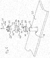
- a machine frame carries in FIG. 1 Overall, the reference numeral 10 and comprises a plurality of rod elements 12, which are cylindrical in total except for a respective foot section 14. Each of the rod elements 12 comprises two likewise cylindrically shaped fastening sections 16. The fastening sections 16 connect the rod elements 12 to a first support element 18 and a second support element 20 via a respective connection device 22. In the in FIG. 1 shown state in which the rod members 12 are connected to the first support member 18 and the second support member 20 via the connecting means 22, they are in an assembled state by forming the machine frame 10.
- FIG. 3 is an area around a connecting device 22 isolated and shown in detail.
- An axial direction 24 is represented by an arrow with the corresponding reference numeral, just as a radial direction 26.
- the axial direction 24 and the radial direction refer to those in the FIG. 3 illustrated rod elements 12.
- the connecting device 22 from FIG. 3 includes an in FIG. 5 in section shown clamping element 30, which in the illustration of FIG. 3 is disposed in an opening 17 of the support member 20.
- the connecting device 22 further comprises a plurality of clamping elements 32, which are designed as clamping screws 33.
- the connecting device 22 comprises a sleeve element 34, which is designed in the manner of a flange and has an outer flange section 36. An outer flange portion 36 abuts axially against the carrier element 20 with a contact surface 38.
- the sleeve member 34 forms a clamping sleeve in the opening 17 of the support member 20.
- the sleeve member 34 has a clamping groove 40 which in FIG. 3 is clearly visible.
- FIG. 5 is the section from the Figures 3 and 4 shown during assembly of the connecting device.
- the clamping element 30 has a clamping joint 40.
- the clamping element 30 has in the in FIG. 5 also shown embodiment five blind holes 52, each carrying a hole-side thread 44.
- the structure of the sleeve member 34 is also clearly visible.
- the sleeve member also includes a sleeve forming radially inner portion 48.
- the chuck 40 extends itself through both the outer flange portion 36 as well as through the sleeve-forming radially inner portion 48th
- the clamping element 30 When mounting the connecting device, the clamping element 30 is guided over the rod member 12 and through the opening 17 therethrough. Thereafter, the sleeve member 34 is guided over the rod member 12 and then the support member 20 is brought exactly to the desired position, wherein the support member 20 is applied to the abutment surface 38 of the outer flange portion 36.
- the clamping elements 32 are guided through the respective through openings 46 in the sleeve member 34 and then the clamping member 30 positioned so that the clamping elements 32 are inserted into the blind holes 42 of the clamping member 30 and there with a respective screw thread 50 in the hole-side threads 44 of the blind holes 42 engage ,
- a gap 54 is formed, which is present annular and circumferentially continuous.
- the gap 54 tapers in a wedge shape in the axial direction 24 toward the outer flange section 36 of the sleeve element 34.
- the clamping element 30 is received in the gap 54.
- the clamping element 30 lies with an outer surface 56, which corresponds to the lateral surface of a cylinder, on which to the outer surface 56 concentrically extending, the gap 54 delimiting carrier element-side clamping surface 52 at.
- the clamping element 30 With an inner surface 58, which corresponds to the lateral surface of a truncated cone, the clamping element 30 is located on a clamping surface 60 which extends concentrically to the inner surface 58 and delimits the gap 54.
- the gap 54 tapers at an angle w, which in the illustration of FIG. 6 to exaggerate the operation is exaggerated.
- Angle w is in the context of the invention preferably 2 ° to 10 °, preferably 3 ° to 8 °, in particular 3.5 ° to 6 °, in particular 4 ° to 5 °, compared to the axial direction 24. This is an advantageous ratio of movement of the clamping element 30 in the gap 54 inside and jamming of the sleeve member 34 on the other hand achieved.
- the taper of the gap is completely caused by the course of the cuff-element-side clamping surface 60 and the inner surface 58 of the clamping element 30 at an angle W, since the carrier element-side clamping surface 52 and the outer surface 56 of the clamping element 30 with respect to the axial direction 24 is not angled.
- the connecting device 22 between the rod member 12 and the support member 20 is braced and thus also the rod member 12 is clamped against the support member 20.
- the advantage here is that by the clamping member 30 during clamping in the gap 54 but only against the support member 20 and the sleeve member 34 does not slide against the rod member 12 so that the relative position of the support member 20, sleeve member 34 and rod member 12 does not change ,
- the clamping member 30 slides with its outer surface 56 along the concentric with the outer surface 56 extending support member side clamping surface 52 and with its inner surface 58 along the cuff member clamping surface 60, which is also concentric with the inner surface 58.
- the gap 54 tapers towards the flange portion 36, the gap 54 is widened by pulling in the clamping member, thereby pressing the contact surface of the sleeve member 34 against the attachment portion 16 of the rod member 12, and at the same time, the outer surface 56 of the clamping member becomes against the support member side clamping surface 52, which limits the gap 54, pressed.
Landscapes
- Engineering & Computer Science (AREA)
- General Engineering & Computer Science (AREA)
- Mechanical Engineering (AREA)
- Clamps And Clips (AREA)
- Mutual Connection Of Rods And Tubes (AREA)
- Absorbent Articles And Supports Therefor (AREA)
Description
- Die Erfindung betrifft ein Maschinengestell, wobei das Maschinengestell mehrere Stabelemente und wenigstens ein, vorzugsweise plattenartig ausgebildetes Trägerelement umfasst, wobei die Stabelemente mittels jeweils einer Verbindungseinrichtung mit dem Trägerelement verbindbar sind, um in einem Montagezustand das Maschinengestell zu bilden. Das Trägerelement ist bei herkömmlichen Maschinengestellen nicht in einfacher Weise mit den Stabelementen verbindbar. Hierzu sind aus dem Stand der Technik lediglich komplexe Verbindungseinrichtungen bekannt, die zwar eine lagegenaue Anbringung des Trägerelements an den Stabelementen ermöglichen, jedoch nicht einfach in ihrer Bedienung sind. Unter einer Öffnung ist vorliegend ein im Trägerelement liegender materialfreier Raum gemeint, der komplett durch Material des Trägerelements umschlossen ist. Unter einer Ausnehmung ist dabei ein materialfreier Raum im Trägerelement zu verstehen, welcher in eine Schmalseite des Trägerelements mündet.
- Aufgabe der vorliegenden Erfindung ist es, ein Maschinengestell bereitzustellen, bei welcher das Trägerelement in einfacher Weise mit den Stabelementen verbindbar ist, um das Maschinengestell in dem Montagezustand zu bilden. Wobei die Verbindung nicht nur einfach zu handhaben sein soll, sondern ebenso eine genaue Positionierung des Trägerelements an den Stabelementen ermöglicht.
- Diese Aufgabe wird durch ein Maschinengestell mit den Merkmalen gemäß Anspruch 1 gelöst. Erfindungsgemäß umfasst die Verbindungseinrichtung wenigstens ein Spannelement, insbesondere in Form einer Spannschraube, ein Klemmelement und ein im Montagezustand als Klemmhülse wirkendes Manschettenelement, wobei die Verbindungseinrichtung in der Öffnung oder Ausnehmung des Trägerelements angeordnet ist, wobei das Manschettenelement flanschartig ausgebildet ist und mit einem äußeren Flanschabschnitt mit einer Anlagefläche axial gegen das Trägerelement anliegt, und wobei das Manschettenelement mit einem hülsenbildenden radial inneren Abschnitt den zylindrisch ausgebildeten Befestigungsabschnitt des Stabelements umgibt und im Montagezustand mit einer Kontaktfläche an den Befestigungsabschnitt klemmend anliegt, wobei in radialer Richtung zwischen dem Manschettenelement und einer die Öffnung oder Ausnehmung begrenzenden Wandung des Trägerelements ein, vorzugsweise ringförmiger, Spalt gebildet ist, der sich in axialer Richtung zu dem äußeren Flanschabschnitt des Manschettenelements hin keilförmig verjüngt, und wobei das Klemmelement in dem Spalt aufgenommen ist und durch Festziehen des Spannelements axial tiefer in den Spalt gezogen wird und hierdurch das Manschettenelement mit seiner Kontaktfläche nach radial innen gegen den Befestigungsabschnitt des Stabelements gepresst wird, wodurch in der Folge die Verbindungseinrichtung zwischen Stabelement und Trägerelement verspannt wird und damit auch das Stabelement klemmend gegen das Trägerelement fixiert wird.
- Bevorzugt ist, wenn der Spalt sich in einem Winkel von 2° bis 10°, vorzugsweise 3° bis 8°, insbesondere 3,5° bis 6°, insbesondere 4° bis 5°, zur axialen Richtung verjüngt. Hierdurch wird ein vorteilhaftes Verhältnis von Bewegung des Klemmelements in den Spalt hinein und Verklemmung des Manschettenelements andererseits erreicht. Insbesondere ist bevorzugt, wenn die manschettenelementseitige Spannfläche und die Innenfläche des Klemmelements in einem Winkel von 2° bis 10°, vorzugsweise 3° bis 8°, insbesondere 3,5° bis 6°, insbesondere 4° bis 5°, zur axialen Richtung verlaufen und hierdurch die Verjüngung des Spalts wenigstens teilweise, insbesondere vollständig erzeugt ist.
- Bei dem erfindungsgemäßen Maschinengestell kann eine Platzierung des Trägerelements über den äußeren Flanschabschnitt mit der Anlagefläche präzise erfolgen, wobei sich Ausrichtung und Lage des Trägerelements beim Festziehen des Spannelements nicht ändern, da das Klemmelement gegen das Manschettenelement und das Trägerelement jedoch nicht unmittelbar gegen das Stabelement verspannt wird. Bei dem vorliegenden Maschinengestell kann also vor dem Festziehen des Spannelements das Trägerelement zu dem Stabelement genau ausgerichtet werden und dann kann das Spannelement festgezogen werden, so dass die einzelnen Teile des Maschinengestells fest miteinander verbunden und verspannt, wobei sich bei diesem Festziehen die Ausrichtung und Lage des Trägerelements zum Stabelement nicht mehr ändert, so dass das Maschinengestell im Montagezustand exakt eingestellt ist.
- Bevorzugt ist dabei, wenn der Flanschabschnitt kreisscheibenförmig ausgebildet ist. Hierdurch kann das Trägerelement, insbesondere wenn der Flanschabschnitt in einer Ausnehmung angeordnet ist, in vorteilhafter Weise entlang der gesamten Erstreckung des kreisscheibenförmigen Flanschabschnitts an diesen angelegt und damit genau positioniert werden.
- Von Vorteil ist auch, wenn eine den Spalt begrenzende trägerelementseitige Spannfläche zylindrisch ausgebildet ist. Die Öffnung beziehungsweise Ausnehmung bei dieser Ausführungsform in einfacher Weise in das Trägerelement eingebracht werden, beispielsweise mittels eines Bohrers, da auch die trägerelementseitige Spannfläche in dieser Ausführungsform zylindrisch ausgebildet ist. Hierdurch lässt sich das Trägerelement in einfacher Weise fertigen.
- Vorteilhaft ist auch, wenn das Klemmelement mit einer Außenfläche, die der Mantelfläche eines Kegelstumpfs oder eines Zylinders entspricht, an einer zur Außenfläche konzentrisch verlaufenden, den Spalt begrenzenden, trägerelementseitigen Spannfläche anliegt. Die Außenfläche des Klemmelements bei dieser Ausführungsform folgt damit dem Verlauf der trägerelementseitigen Spannfläche. Hierdurch kann ein Gleiten mit geringem Widerstand der trägerelementseitigen Spannfläche über die Außenfläche des Klemmelements gewährleistet werden. Damit verläuft das Ziehen des Klemmelements in den Spalt durch Festziehen des Spannelements in vorteilhafter und leichtgängiger Weise, da ein geringer Widerstand überwunden werden muss.
- Von Vorteil ist auch, wenn das Klemmelement mit einer Innenfläche, die der Mantelfläche eines Kegelstumpfs oder eines Zylinders entspricht, an einer zur Innenfläche konzentrisch verlaufenden, den Spalt begrenzenden, manschettenelementseitigen Spannfläche anliegt. Hierdurch gleitet das Klemmelement beim Festziehen des Spannelements in vorteilhafter Weise über die manschettenelementseitige Spannfläche, ohne dass es zu einem Verhaken oder einem Klemmen kommen kann.
- Von Vorteil ist auch, wenn das Manschettenelement und/oder das Klemmelement eine von innen nach außen, insbesondere radial verlaufende Spannfuge aufweist. Beim Hineinziehen des Klemmelements über das Spannelement in den Spalt wird das Manschettenelement genau wie das Klemmelement durch die Spannfuge in umfänglicher Richtung komprimierbar, was das Verspannen einfacher gestaltet und einen höheren Grad an Verspannung bei geringerer Spannkraft ermöglicht.
- Vorteilhaft ist auch, wenn mehrere Spannelemente vorgesehen sind, hierdurch ist es möglich, dass das Klemmelement über seine umfängliche Erstreckung hinweg gleichmäßig in den Spalt gezogen wird, was die Genauigkeit der der Montage erhöht.
- Vorteilhaft ist auch, wenn der Flanschabschnitt wenigstens eine Durchgangsöffnung aufweist, durch die sich das Spannelement im Montagezustand erstreckt. Dies stellt eine einfache Möglichkeit dar, das Spannelement mit dem Flanschabschnitt zu verbinden. Das Spannelement kann in dieser Ausführungsform in einfacher Weise durch die Durchgangsöffnung hindurchgeführt werden und liegt dann beispielsweise mit einem Schraubenkopf an dem Flanschabschnitt an, wobei ein dem Schraubenkopf gegenüberliegendes Ende des Spannelements in das Klemmelement eingreift.
- Vorteilhaft ist auch, wenn das Klemmelement ein Loch, vorzugsweise ein Sackloch aufweist, in das das Spannelement im Montagezustand eingreift, vorzugsweise über ein verspannelementseitiges Gewinde in ein lochseitiges Gewinde eingreift. Hierdurch kann in einfacher Weise ein zuverlässiger Kontakt zwischen dem Klemmelement und dem Spannelement hergestellt werden, so dass das Klemmelement in einfacher Weise in den Spalt ziehbar ist.
- Vorteilhaft ist auch, wenn das Trägerelement eine flächige Erstreckung aufweist, die orthogonal zu einer Erstreckung des Stabelements ist. Dies stellt eine einfach zu realisierende Ausführungsform dar, die für eine Vielzahl von Anwendungen des Maschinengestells geeignet ist.
- Weitere Merkmale, Anwendungsmöglichkeiten und Vorteile der Erfindung ergeben sich aus der nachfolgenden Beschreibung von Ausführungsbeispielen der Erfindung, die anhand der Zeichnung erläutert werden, wobei die beschriebenen Merkmale sowohl in Alleinstellung als auch in unterschiedlichen Kombinationen für die Erfindung wichtig sein können, ohne dass hierauf nochmals explizit hingewiesen wird. Es zeigen:
- Figur 1
- ein erfindungsgemäßes Maschinengestell in einer perspektivischen Darstellung;
- Figur 2
- das Maschinengestell aus
Figur 1 in einer Seitenansicht; - Figur 3
- einen vergrößerten Ausschnitt aus
Figur 1 um eine Verbindungseinrichtung herum in einer perspektivischen Darstellung; - Figur 4
- eine weitere Darstellung des Bereichs aus
Figur 3 um eine Verbindungseinrichtung herum; - Figur 5
- die Verbindungseinrichtung aus
Figur 4 in explosionsartiger Darstellung; und - Figur 6
- eine Schnittdarstellung gemäß Pfeil VI in
Fig. 4 . - Ein Maschinengestell trägt in
Figur 1 insgesamt das Bezugszeichen 10 und umfasst mehrere Stabelemente 12, die insgesamt bis auf einen jeweiligen Fußabschnitt 14 zylindrisch ausgebildet sind. Jedes der Stabelemente 12 umfasst jeweils zwei ebenfalls zylindrisch ausgebildete Befestigungsabschnitte 16. Über die Befestigungsabschnitte 16 sind die Stabelemente 12 jeweils mit einem ersten Trägerelement 18 und einem zweiten Trägerelement 20 über jeweils eine Verbindungseinrichtung 22, verbunden. In dem inFigur 1 gezeigten Zustand, in dem die Stabelemente 12 mit dem ersten Trägerelement 18 und mit dem zweiten Trägerelement 20 über die Verbindungseinrichtung 22 verbunden sind, befinden diese sich in einem Montagezustand, indem sie das Maschinengestell 10 bilden. - In
Figur 3 ist ein Bereich um eine Verbindungseinrichtung 22 vereinzelt und im Detail dargestellt. Eine axiale Richtung 24 ist durch einen Pfeil mit dem entsprechenden Bezugszeichen dargestellt, genau wie eine radiale Richtung 26. Dabei beziehen sich die axiale Richtung 24 und die radiale Richtung jeweils auf die in derFigur 3 dargestellten Stabelemente 12. - Die Verbindungseinrichtung 22 aus
Figur 3 umfasst ein inFigur 5 im Schnitt gezeigtes Klemmelement 30, welches in der Darstellung vonFigur 3 in einer Öffnung 17 des Trägerelements 20 angeordnet ist. Die Verbindungseinrichtung 22 umfasst des Weiteren mehrere Spannelemente 32, die als Spannschrauben 33 ausgeführt sind. Des Weiteren umfasst die Verbindungseinrichtung 22 ein Manschettenelement 34, das flanschartig ausgebildet ist und einen äußeren Flanschabschnitt 36 aufweist. Ein äußerer Flanschabschnitt 36 liegt mit einer Anlagefläche 38 axial gegen das Trägerelement 20 an. In dem inFigur 3 gezeigten Montagezustand bildet das Manschettenelement 34 eine Klemmhülse in der Öffnung 17 des Trägerelements 20. Das Manschettenelement 34 weist eine Spannfuge 40 auf, die inFigur 3 gut sichtbar dargestellt ist. - In
Figur 5 ist der Abschnitt aus denFiguren 3 und4 während der Montage der Verbindungseinrichtung dargestellt. In dieser Darstellung ist ersichtlich, dass auch das Klemmelement 30 eine Spannfuge 40 aufweist. Das Klemmelement 30 weist in der inFigur 5 gezeigten Ausführungsform außerdem fünf Sacklöcher 52 auf, welche jeweils ein lochseitiges Gewinde 44 tragen. In der Darstellung vonFigur 5 ist auch die Struktur des Manschettenelements 34 gut erkennbar. Neben dem äußeren Flanschabschnitt 36, der mit den Sacklöchern 42 des Klemmelements fluchtende Durchgangsöffnungen 46 aufweist, umfasst das Manschettenelement auch einen hülsenbildenden radial inneren Abschnitt 48. Die Spannfuge 40 erstreckt sich sowohl durch den äußeren Flanschabschnitt 36 wie auch durch den hülsenbildenden radial inneren Abschnitt 48. - Bei der Montage der Verbindungseinrichtung wird das Klemmelement 30 über das Stabelement 12 geführt und durch die Öffnung 17 hindurch. Danach wird das Manschettenelement 34 über das Stabelement 12 geführt und dann das Trägerelement 20 genau auf die gewünschte Position gebracht, wobei das Trägerelement 20 an der Anlagefläche 38 des äußeren Flanschabschnitts 36 angelegt wird. Die Spannelemente 32 werden durch die jeweiligen Durchgangsöffnungen 46 im Manschettenelement 34 geführt und dann das Klemmelement 30 derart positioniert, dass die Spannelemente 32 in die Sacklöcher 42 des Klemmelements 30 eingeführt werden und dort mit einem jeweiligen Schraubengewinde 50 in die lochseitigen Gewinde 44 der Sacklöcher 42 eingreifen.
- In der Darstellung von
Figur 6 ist ersichtlich, dass in radialer Richtung 26 zwischen dem Manschettenelement 34 und einer die Öffnung 17 begrenzenden Wandung 52, welche gleichzeitig eine trägerelementseitige Spannfläche 52 bildet, ein Spalt 54 gebildet ist, der vorliegend ringförmig und in Umfangsrichtung durchgehend ausgebildet ist. Der Spalt 54 verjüngt sich dabei keilförmig in axialer Richtung 24 zu dem äußeren Flanschabschnitt 36 des Manschettenelements 34 hin. Das Klemmelement 30 ist in dem Spalt 54 aufgenommen. Das Klemmelement 30 liegt mit einer Außenfläche 56, die der Mantelfläche eines Zylinders entspricht, an der zu der Außenfläche 56 konzentrisch verlaufenden, den Spalt 54 begrenzenden trägerelementseitigen Spannfläche 52 an. Mit einer Innenfläche 58, die der Mantelfläche eines Kegelstumpfs entspricht, liegt das Klemmelement 30 an einer zur Innenfläche 58 konzentrisch verlaufenden, den Spalt 54 begrenzenden, manschettenelementseitigen Spannfläche 60 an. - Der Spalt 54 verjüngt sich in einem Winkel w, der in der Darstellung von
Figur 6 zur Verdeutlichung der Funktionsweise übertrieben dargestellt ist. Winkel w beträgt im Sinne der Erfindung vorzugsweise 2° bis 10°, vorzugsweise 3° bis 8°, insbesondere 3,5° bis 6°, insbesondere 4° bis 5°, ggü der axialen Richtung 24. Hierdurch wird ein vorteilhaftes Verhältnis von Bewegung des Klemmelements 30 in den Spalt 54 hinein und Verklemmung des Manschettenelements 34 andererseits erreicht. Vorliegend ist die Verjüngung des Spalts vollständig durch den Verlauf der manschettenelementseitigen Spannfläche 60 und der Innenfläche 58 des Klemmelements 30 im Winkel W verursacht, da die trägerelementseitige Spannfläche 52 und die Außenfläche 56 des Klemmelements 30 gegenüber der axialen Richtung 24 nicht abgewinkelt verlaufen. - Nachfolgend wird die Montage des Trägerelements 20 über die Verbindungseinrichtung 22 anhand der
Figur 6 näher beschrieben. In dem inFigur 6 gezeigten Zustand, in dem das Klemmelement 30 in dem Spalt 54 aufgenommen ist, wird durch Festziehen des Spannelements 32 das Klemmelement 30 axial tiefer in den Spalt 54 gezogen, da das Gewinde 50 des Spannelements 32 in das Gewinde 44 im Sackloch 42 des Klemmelements 30 eingreift. Durch das Ziehen des Klemmelements in den Spalt 54 wird das Manschettenelement 34 mit seiner Kontaktfläche 62 nach radial innen, also entgegen der radialen Richtung 26, gegen den Befestigungsabschnitt 16 des Stabelements 12 gepresst. Hierdurch wird die Verbindungseinrichtung 22 zwischen dem Stabelement 12 und dem Trägerelement 20 verspannt und damit auch das Stabelement 12 klemmend gegen das Trägerelement 20 fixiert. Vorteilhaft ist dabei, dass indem dass indem das Klemmelement 30 beim Verspannen im Spalt 54 nur gegen das Trägerelement 20 und das Manschettenelement 34 jedoch nicht gegen das Stabelement 12 gleitet, so dass sich die relative Position von Trägerelement 20, Manschettenelement 34 und Stabelement 12 nicht ändert. - Beim Festziehen der Verbindungseinrichtung 22 gleitet das Klemmelement 30 mit seiner Außenfläche 56 entlang der konzentrisch zur Außenfläche 56 verlaufenden trägerelementseitigen Spannfläche 52 und mit seiner Innenfläche 58 entlang der manschettenelementseitigen Spannfläche 60, welche ebenfalls konzentrisch zur Innenfläche 58 verläuft. Da sich der Spalt 54 zum Flanschabschnitt 36 hin verjüngt, wird der Spalt 54 durch das Hineinziehen des Klemmelements quasi aufgeweitet und hierdurch die Kontaktfläche des Manschettenelements 34 gegen den Befestigungsabschnitt 16 des Stabelements 12 gepresst, und gleichzeitig wird die Außenfläche 56 des Klemmelements gegen die trägerelementseitige Spannfläche 52, welche den Spalt 54 begrenzt, gepresst.
Claims (12)
- Maschinengestell (10), wobei das Maschinengestell (10) mehrere Stabelemente (12) mit einem zylindrisch ausgebildeten Befestigungsabschnitt (16) und wenigstens ein, vorzugsweise plattenartig ausgebildetes Trägerelement (18, 20) mit Öffnungen (17) oder Ausnehmungen für die Stabelemente (12) umfasst, wobei die Stabelemente (12) mittels jeweils einer Verbindungseinrichtung (22) in einer jeweiligen Öffnung (17) oder Ausnehmung mit dem Trägerelement (18, 20) verbindbar sind, um in einem Montagezustand (MS) das Maschinengestell (10) zu bilden, mit einer axialen Richtung (24) und einer radialen Richtung (26), wobei die Verbindungseinrichtung (22), wenigstens ein Spannelement (32), insbesondere in Form einer Spannschraube (32), ein Klemmelement (30) und ein im Montagezustand (MS) als Klemmhülse wirkendes Manschettenelement (34) umfasst und in der Öffnung (17) oder Ausnehmung des Trägerelements (18, 20) angeordnet ist, wobei das Manschettenelement (34) flanschartig ausgebildet ist und mit einem äußeren Flanschabschnitt (36) mit einer Anlagefläche (38) axial gegen das Trägerelement (18, 20) anliegt, und wobei das Manschettenelement (34) mit einem hülsenbildenden radial inneren Abschnitt (48) den zylindrisch ausgebildeten Befestigungsabschnitt (16) des Stabelements (12) umgibt und im Montagezustand (MS) mit einer Kontaktfläche (62) an dem Befestigungsabschnitt (16) klemmend anliegt, wobei in radialer Richtung (26) zwischen dem Manschettenelement (34) und einer die Öffnung (17) oder Ausnehmung begrenzenden Wandung (52) des Trägerelements (18, 20) ein, vorzugsweise ringförmiger, Spalt (54) gebildet ist, der sich in axialer Richtung (24) zu dem äußeren Flanschabschnitt (36) des Manschettenelements (34) hin keilförmig verjüngt, und wobei das Klemmelement (30) in dem Spalt (54) aufgenommen ist und durch Festziehen des Spannelements (32) axial tiefer in den Spalt (54) gezogen wird und hierdurch das Manschettenelement (34) mit seiner Kontaktfläche (62) nach radial innen gegen den Befestigungsabschnitt (16) des Stabelements (12) gepresst wird, wodurch in der Folge die Verbindungseinrichtung (22) zwischen Stabelement (12) und Trägerelement (18, 20) verspannt wird und damit auch das Stabelement (12) klemmend gegen das Trägerelement (18, 20) fixiert wird.
- Maschinengestell (10) nach Anspruch 1, dadurch gekennzeichnet, dass der Flanschabschnitt (36) kreisscheibenförmig ausgebildet ist.
- Maschinengestell (10) nach Anspruch 1 oder 2, dadurch gekennzeichnet, dass eine den Spalt (54) begrenzende trägerelementseitige Spannfläche (52) zylindrisch ausgebildet ist.
- Maschinengestell (10) nach einem oder mehreren der vorangegangenen Ansprüche 1 bis 3, dadurch gekennzeichnet, dass das Klemmelement (30) mit einer Außenfläche (56), die der Mantelfläche eines Kegelstumpfs oder eines Zylinders entspricht, an einer zur Außenfläche (56) konzentrisch verlaufenden, den Spalt (54) begrenzenden, trägerelementseitigen Spannfläche (52) anliegt.
- Maschinengestell (10) nach einem oder mehreren der vorangegangenen Ansprüche, dadurch gekennzeichnet, dass das Klemmelement (30) mit einer Innenfläche (58), die der Mantelfläche eines Kegelstumpfs oder eines Zylinders entspricht, an einer zur Innenfläche (58) konzentrisch verlaufenden, den Spalt (54) begrenzenden, manschettenelementseitigen Spannfläche (60) anliegt.
- Maschinengestell (10) nach einem oder mehreren der vorangegangenen Ansprüche, dadurch gekennzeichnet, dass der Spalt (54) sich in einem Winkel (w) von 2° bis 10°, vorzugsweise 3° bis 8°, insbesondere 3,5° bis 6°, insbesondere 4° bis 5°, zu der axialen Richtung (24) verjüngt, vorzugsweise dass eine Innenfläche (58) des Klemmelements (30) und eine manschettenelementseitige Spannfläche (60) in einem Winkel (w) von 2° bis 10°, vorzugsweise 3° bis 8°, insbesondere 3,5° bis 6°, insbesondere 4° bis 5°, zu der axialen Richtung (24) verlaufen, wodurch die Verjüngung des Spalts (54) wenigstens teilweise, insbesondere vollständig verursacht ist.
- Maschinengestell (10) nach einem oder mehreren der vorangegangenen Ansprüche, dadurch gekennzeichnet, dass das Manschettenelement (34) und/oder das Klemmelement (30) eine von innen nach außen verlaufende Spannfuge (40) aufweisen.
- Maschinengestell (10) nach einem oder mehreren der vorangegangenen Ansprüche, dadurch gekennzeichnet, dass sie mehrere Spannelemente (32) vorgesehen sind.
- Maschinengestell (10) nach einem oder mehreren der vorangegangenen Ansprüche, dadurch gekennzeichnet, dass der Flanschabschnitt (36) wenigstens eine Durchgangsöffnung (46) aufweist, durch die sich das Spannelement (32) im Montagezustand (MS) erstreckt.
- Maschinengestell (10) nach einem oder mehreren der vorangegangenen Ansprüche, dadurch gekennzeichnet, dass das Klemmelement (30) ein Loch (42), vorzugsweise ein Sackloch (42) aufweist, in das das Spannelement (32) im Montagezustand eingreift, vorzugsweise über ein spannelementseitiges Gewinde (50) in ein lochseitiges Gewinde (44) eingreift.
- Maschinengestell (10) nach einem oder mehreren der vorangegangenen Ansprüche, dadurch gekennzeichnet, dass das Trägerelement (18, 20) eine flächige Erstreckung aufweist, die orthogonal zu einer Erstreckung des Stabelements (12) ist.
- Maschinengestell (10) nach einem oder mehreren der vorangegangenen Ansprüche, dadurch gekennzeichnet, dass wenigstens eines der Stabelemente (12) ein Rohr, insbesondere ein Edelstahlrohr, ist.
Applications Claiming Priority (2)
| Application Number | Priority Date | Filing Date | Title |
|---|---|---|---|
| DE102016109929.5A DE102016109929B3 (de) | 2016-05-30 | 2016-05-30 | Tampondruckmaschinengestell |
| EP17169784.0A EP3251847B1 (de) | 2016-05-30 | 2017-05-05 | Tampondruckmaschinengestell |
Related Parent Applications (2)
| Application Number | Title | Priority Date | Filing Date |
|---|---|---|---|
| EP17169784.0A Division EP3251847B1 (de) | 2016-05-30 | 2017-05-05 | Tampondruckmaschinengestell |
| EP17169784.0A Division-Into EP3251847B1 (de) | 2016-05-30 | 2017-05-05 | Tampondruckmaschinengestell |
Publications (2)
| Publication Number | Publication Date |
|---|---|
| EP3441225A1 true EP3441225A1 (de) | 2019-02-13 |
| EP3441225B1 EP3441225B1 (de) | 2019-09-25 |
Family
ID=58672457
Family Applications (2)
| Application Number | Title | Priority Date | Filing Date |
|---|---|---|---|
| EP18198752.0A Active EP3441225B1 (de) | 2016-05-30 | 2017-05-05 | Maschinengestell |
| EP17169784.0A Active EP3251847B1 (de) | 2016-05-30 | 2017-05-05 | Tampondruckmaschinengestell |
Family Applications After (1)
| Application Number | Title | Priority Date | Filing Date |
|---|---|---|---|
| EP17169784.0A Active EP3251847B1 (de) | 2016-05-30 | 2017-05-05 | Tampondruckmaschinengestell |
Country Status (3)
| Country | Link |
|---|---|
| EP (2) | EP3441225B1 (de) |
| DE (1) | DE102016109929B3 (de) |
| DK (1) | DK3441225T3 (de) |
Citations (3)
| Publication number | Priority date | Publication date | Assignee | Title |
|---|---|---|---|---|
| GB736312A (en) * | 1951-08-04 | 1955-09-07 | Guy Leslie Murray | Means for printing or decorating ceramic ware |
| DE3926146A1 (de) * | 1989-08-08 | 1991-02-21 | Werner Goekeler | Vorrichtung |
| DE29605123U1 (de) * | 1996-03-20 | 1997-07-17 | Morlock, Rudi, 72270 Baiersbronn | Tampondruckmaschine |
Family Cites Families (1)
| Publication number | Priority date | Publication date | Assignee | Title |
|---|---|---|---|---|
| DE8419344U1 (de) * | 1984-06-28 | 1984-08-09 | KEUCO Paul Keune GmbH & Co KG, 5870 Hemer | Rohrdübel |
-
2016
- 2016-05-30 DE DE102016109929.5A patent/DE102016109929B3/de not_active Expired - Fee Related
-
2017
- 2017-05-05 EP EP18198752.0A patent/EP3441225B1/de active Active
- 2017-05-05 DK DK18198752.0T patent/DK3441225T3/da active
- 2017-05-05 EP EP17169784.0A patent/EP3251847B1/de active Active
Patent Citations (3)
| Publication number | Priority date | Publication date | Assignee | Title |
|---|---|---|---|---|
| GB736312A (en) * | 1951-08-04 | 1955-09-07 | Guy Leslie Murray | Means for printing or decorating ceramic ware |
| DE3926146A1 (de) * | 1989-08-08 | 1991-02-21 | Werner Goekeler | Vorrichtung |
| DE29605123U1 (de) * | 1996-03-20 | 1997-07-17 | Morlock, Rudi, 72270 Baiersbronn | Tampondruckmaschine |
Also Published As
| Publication number | Publication date |
|---|---|
| EP3441225B1 (de) | 2019-09-25 |
| DE102016109929B3 (de) | 2017-09-07 |
| EP3251847A3 (de) | 2018-02-14 |
| DK3441225T3 (da) | 2020-01-06 |
| EP3251847A2 (de) | 2017-12-06 |
| EP3251847B1 (de) | 2019-03-20 |
Similar Documents
| Publication | Publication Date | Title |
|---|---|---|
| DE102007004383A1 (de) | Ausgewuchtetes Ausbohrwerkzeug mit Klemmeinrichtung | |
| DE102009022191B3 (de) | Fadenführeranordnung einer Kettenwirkmaschine | |
| DE2544498C3 (de) | Gewindering | |
| DE3013874C2 (de) | Spannsatz in Doppelausführung zur Nabenbefestigung | |
| DE1085721B (de) | Klemmverbindung | |
| DE2256306A1 (de) | Spannhuelsenanordnung | |
| DE69022957T2 (de) | Spanner. | |
| DE60038654T2 (de) | Klemmhalterung für Stütz- und Verbindungselemente | |
| DE69514982T2 (de) | Verfahren und Vorrichtung zum Verlängern und zum Entspannen eines Zapfens oder dergleichen | |
| DE3300227C2 (de) | Vorrichtung zur lösbaren Verbindung von Greiferschienenteilen der Greiferschienen in einer Transfer-Presse | |
| EP3500786A1 (de) | Sicherungskralle | |
| DE10348875A1 (de) | Vorrichtung und Verfahren zum Verbinden von zwei teleskopierenden Rohren mit einem Befestigungselement | |
| EP0846908A1 (de) | Verbindung zwischen einem Rohr und einem Formteil | |
| DE102013103913A1 (de) | Spanner | |
| EP3441225B1 (de) | Maschinengestell | |
| DE2036065A1 (de) | Mechanische Verbindung | |
| DE3501583C2 (de) | ||
| DE102017113339A1 (de) | Zylindervorrichtung | |
| DE2604669A1 (de) | Kupplung | |
| DE2836747B2 (de) | Bohrstabilisator | |
| DE202016102853U1 (de) | Tampondruckmaschinengestell und Maschinengestell | |
| DE102012110338A1 (de) | Schraubverbindungsanordnung | |
| DE102004044055A1 (de) | Toleranzausgleichsvorrichtung für zwei miteinander zu verschraubende Bauteile | |
| DE1961980B2 (de) | Nabenbefestigung | |
| DE202007005772U1 (de) | Spannvorrichtungsbaugruppe für eine Maschine |
Legal Events
| Date | Code | Title | Description |
|---|---|---|---|
| PUAI | Public reference made under article 153(3) epc to a published international application that has entered the european phase |
Free format text: ORIGINAL CODE: 0009012 |
|
| STAA | Information on the status of an ep patent application or granted ep patent |
Free format text: STATUS: THE APPLICATION HAS BEEN PUBLISHED |
|
| AC | Divisional application: reference to earlier application |
Ref document number: 3251847 Country of ref document: EP Kind code of ref document: P |
|
| AK | Designated contracting states |
Kind code of ref document: A1 Designated state(s): AL AT BE BG CH CY CZ DE DK EE ES FI FR GB GR HR HU IE IS IT LI LT LU LV MC MK MT NL NO PL PT RO RS SE SI SK SM TR |
|
| AX | Request for extension of the european patent |
Extension state: BA ME |
|
| STAA | Information on the status of an ep patent application or granted ep patent |
Free format text: STATUS: REQUEST FOR EXAMINATION WAS MADE |
|
| GRAP | Despatch of communication of intention to grant a patent |
Free format text: ORIGINAL CODE: EPIDOSNIGR1 |
|
| STAA | Information on the status of an ep patent application or granted ep patent |
Free format text: STATUS: GRANT OF PATENT IS INTENDED |
|
| 17P | Request for examination filed |
Effective date: 20190315 |
|
| RBV | Designated contracting states (corrected) |
Designated state(s): AL AT BE BG CH CY CZ DE DK EE ES FI FR GB GR HR HU IE IS IT LI LT LU LV MC MK MT NL NO PL PT RO RS SE SI SK SM TR |
|
| INTG | Intention to grant announced |
Effective date: 20190424 |
|
| GRAS | Grant fee paid |
Free format text: ORIGINAL CODE: EPIDOSNIGR3 |
|
| GRAA | (expected) grant |
Free format text: ORIGINAL CODE: 0009210 |
|
| STAA | Information on the status of an ep patent application or granted ep patent |
Free format text: STATUS: THE PATENT HAS BEEN GRANTED |
|
| AC | Divisional application: reference to earlier application |
Ref document number: 3251847 Country of ref document: EP Kind code of ref document: P |
|
| AK | Designated contracting states |
Kind code of ref document: B1 Designated state(s): AL AT BE BG CH CY CZ DE DK EE ES FI FR GB GR HR HU IE IS IT LI LT LU LV MC MK MT NL NO PL PT RO RS SE SI SK SM TR |
|
| REG | Reference to a national code |
Ref country code: GB Ref legal event code: FG4D Free format text: NOT ENGLISH |
|
| REG | Reference to a national code |
Ref country code: CH Ref legal event code: EP |
|
| REG | Reference to a national code |
Ref country code: AT Ref legal event code: REF Ref document number: 1183431 Country of ref document: AT Kind code of ref document: T Effective date: 20191015 |
|
| REG | Reference to a national code |
Ref country code: IE Ref legal event code: FG4D Free format text: LANGUAGE OF EP DOCUMENT: GERMAN |
|
| REG | Reference to a national code |
Ref country code: DE Ref legal event code: R096 Ref document number: 502017002414 Country of ref document: DE |
|
| REG | Reference to a national code |
Ref country code: CH Ref legal event code: NV Representative=s name: DREISS PATENTANWAELTE PARTG MBB, DE |
|
| REG | Reference to a national code |
Ref country code: DK Ref legal event code: T3 Effective date: 20191219 |
|
| REG | Reference to a national code |
Ref country code: SE Ref legal event code: TRGR |
|
| REG | Reference to a national code |
Ref country code: NL Ref legal event code: MP Effective date: 20190925 |
|
| PG25 | Lapsed in a contracting state [announced via postgrant information from national office to epo] |
Ref country code: HR Free format text: LAPSE BECAUSE OF FAILURE TO SUBMIT A TRANSLATION OF THE DESCRIPTION OR TO PAY THE FEE WITHIN THE PRESCRIBED TIME-LIMIT Effective date: 20190925 Ref country code: FI Free format text: LAPSE BECAUSE OF FAILURE TO SUBMIT A TRANSLATION OF THE DESCRIPTION OR TO PAY THE FEE WITHIN THE PRESCRIBED TIME-LIMIT Effective date: 20190925 Ref country code: BG Free format text: LAPSE BECAUSE OF FAILURE TO SUBMIT A TRANSLATION OF THE DESCRIPTION OR TO PAY THE FEE WITHIN THE PRESCRIBED TIME-LIMIT Effective date: 20191225 Ref country code: NO Free format text: LAPSE BECAUSE OF FAILURE TO SUBMIT A TRANSLATION OF THE DESCRIPTION OR TO PAY THE FEE WITHIN THE PRESCRIBED TIME-LIMIT Effective date: 20191225 Ref country code: LT Free format text: LAPSE BECAUSE OF FAILURE TO SUBMIT A TRANSLATION OF THE DESCRIPTION OR TO PAY THE FEE WITHIN THE PRESCRIBED TIME-LIMIT Effective date: 20190925 |
|
| REG | Reference to a national code |
Ref country code: LT Ref legal event code: MG4D |
|
| PG25 | Lapsed in a contracting state [announced via postgrant information from national office to epo] |
Ref country code: LV Free format text: LAPSE BECAUSE OF FAILURE TO SUBMIT A TRANSLATION OF THE DESCRIPTION OR TO PAY THE FEE WITHIN THE PRESCRIBED TIME-LIMIT Effective date: 20190925 Ref country code: GR Free format text: LAPSE BECAUSE OF FAILURE TO SUBMIT A TRANSLATION OF THE DESCRIPTION OR TO PAY THE FEE WITHIN THE PRESCRIBED TIME-LIMIT Effective date: 20191226 Ref country code: RS Free format text: LAPSE BECAUSE OF FAILURE TO SUBMIT A TRANSLATION OF THE DESCRIPTION OR TO PAY THE FEE WITHIN THE PRESCRIBED TIME-LIMIT Effective date: 20190925 |
|
| PG25 | Lapsed in a contracting state [announced via postgrant information from national office to epo] |
Ref country code: EE Free format text: LAPSE BECAUSE OF FAILURE TO SUBMIT A TRANSLATION OF THE DESCRIPTION OR TO PAY THE FEE WITHIN THE PRESCRIBED TIME-LIMIT Effective date: 20190925 Ref country code: PL Free format text: LAPSE BECAUSE OF FAILURE TO SUBMIT A TRANSLATION OF THE DESCRIPTION OR TO PAY THE FEE WITHIN THE PRESCRIBED TIME-LIMIT Effective date: 20190925 Ref country code: AL Free format text: LAPSE BECAUSE OF FAILURE TO SUBMIT A TRANSLATION OF THE DESCRIPTION OR TO PAY THE FEE WITHIN THE PRESCRIBED TIME-LIMIT Effective date: 20190925 Ref country code: ES Free format text: LAPSE BECAUSE OF FAILURE TO SUBMIT A TRANSLATION OF THE DESCRIPTION OR TO PAY THE FEE WITHIN THE PRESCRIBED TIME-LIMIT Effective date: 20190925 Ref country code: PT Free format text: LAPSE BECAUSE OF FAILURE TO SUBMIT A TRANSLATION OF THE DESCRIPTION OR TO PAY THE FEE WITHIN THE PRESCRIBED TIME-LIMIT Effective date: 20200127 Ref country code: RO Free format text: LAPSE BECAUSE OF FAILURE TO SUBMIT A TRANSLATION OF THE DESCRIPTION OR TO PAY THE FEE WITHIN THE PRESCRIBED TIME-LIMIT Effective date: 20190925 Ref country code: NL Free format text: LAPSE BECAUSE OF FAILURE TO SUBMIT A TRANSLATION OF THE DESCRIPTION OR TO PAY THE FEE WITHIN THE PRESCRIBED TIME-LIMIT Effective date: 20190925 |
|
| PG25 | Lapsed in a contracting state [announced via postgrant information from national office to epo] |
Ref country code: SK Free format text: LAPSE BECAUSE OF FAILURE TO SUBMIT A TRANSLATION OF THE DESCRIPTION OR TO PAY THE FEE WITHIN THE PRESCRIBED TIME-LIMIT Effective date: 20190925 Ref country code: SM Free format text: LAPSE BECAUSE OF FAILURE TO SUBMIT A TRANSLATION OF THE DESCRIPTION OR TO PAY THE FEE WITHIN THE PRESCRIBED TIME-LIMIT Effective date: 20190925 Ref country code: IS Free format text: LAPSE BECAUSE OF FAILURE TO SUBMIT A TRANSLATION OF THE DESCRIPTION OR TO PAY THE FEE WITHIN THE PRESCRIBED TIME-LIMIT Effective date: 20200224 Ref country code: CZ Free format text: LAPSE BECAUSE OF FAILURE TO SUBMIT A TRANSLATION OF THE DESCRIPTION OR TO PAY THE FEE WITHIN THE PRESCRIBED TIME-LIMIT Effective date: 20190925 |
|
| REG | Reference to a national code |
Ref country code: DE Ref legal event code: R097 Ref document number: 502017002414 Country of ref document: DE |
|
| PG2D | Information on lapse in contracting state deleted |
Ref country code: IS |
|
| PG25 | Lapsed in a contracting state [announced via postgrant information from national office to epo] |
Ref country code: IS Free format text: LAPSE BECAUSE OF FAILURE TO SUBMIT A TRANSLATION OF THE DESCRIPTION OR TO PAY THE FEE WITHIN THE PRESCRIBED TIME-LIMIT Effective date: 20200126 |
|
| PLBE | No opposition filed within time limit |
Free format text: ORIGINAL CODE: 0009261 |
|
| STAA | Information on the status of an ep patent application or granted ep patent |
Free format text: STATUS: NO OPPOSITION FILED WITHIN TIME LIMIT |
|
| 26N | No opposition filed |
Effective date: 20200626 |
|
| PG25 | Lapsed in a contracting state [announced via postgrant information from national office to epo] |
Ref country code: SI Free format text: LAPSE BECAUSE OF FAILURE TO SUBMIT A TRANSLATION OF THE DESCRIPTION OR TO PAY THE FEE WITHIN THE PRESCRIBED TIME-LIMIT Effective date: 20190925 |
|
| PG25 | Lapsed in a contracting state [announced via postgrant information from national office to epo] |
Ref country code: MC Free format text: LAPSE BECAUSE OF FAILURE TO SUBMIT A TRANSLATION OF THE DESCRIPTION OR TO PAY THE FEE WITHIN THE PRESCRIBED TIME-LIMIT Effective date: 20190925 |
|
| REG | Reference to a national code |
Ref country code: BE Ref legal event code: MM Effective date: 20200531 |
|
| PG25 | Lapsed in a contracting state [announced via postgrant information from national office to epo] |
Ref country code: LU Free format text: LAPSE BECAUSE OF NON-PAYMENT OF DUE FEES Effective date: 20200505 |
|
| PG25 | Lapsed in a contracting state [announced via postgrant information from national office to epo] |
Ref country code: IE Free format text: LAPSE BECAUSE OF NON-PAYMENT OF DUE FEES Effective date: 20200505 |
|
| PG25 | Lapsed in a contracting state [announced via postgrant information from national office to epo] |
Ref country code: BE Free format text: LAPSE BECAUSE OF NON-PAYMENT OF DUE FEES Effective date: 20200531 |
|
| PG25 | Lapsed in a contracting state [announced via postgrant information from national office to epo] |
Ref country code: TR Free format text: LAPSE BECAUSE OF FAILURE TO SUBMIT A TRANSLATION OF THE DESCRIPTION OR TO PAY THE FEE WITHIN THE PRESCRIBED TIME-LIMIT Effective date: 20190925 Ref country code: MT Free format text: LAPSE BECAUSE OF FAILURE TO SUBMIT A TRANSLATION OF THE DESCRIPTION OR TO PAY THE FEE WITHIN THE PRESCRIBED TIME-LIMIT Effective date: 20190925 Ref country code: CY Free format text: LAPSE BECAUSE OF FAILURE TO SUBMIT A TRANSLATION OF THE DESCRIPTION OR TO PAY THE FEE WITHIN THE PRESCRIBED TIME-LIMIT Effective date: 20190925 |
|
| PG25 | Lapsed in a contracting state [announced via postgrant information from national office to epo] |
Ref country code: MK Free format text: LAPSE BECAUSE OF FAILURE TO SUBMIT A TRANSLATION OF THE DESCRIPTION OR TO PAY THE FEE WITHIN THE PRESCRIBED TIME-LIMIT Effective date: 20190925 |
|
| P01 | Opt-out of the competence of the unified patent court (upc) registered |
Effective date: 20230519 |
|
| PGFP | Annual fee paid to national office [announced via postgrant information from national office to epo] |
Ref country code: GB Payment date: 20250519 Year of fee payment: 9 Ref country code: DK Payment date: 20250521 Year of fee payment: 9 |
|
| PGFP | Annual fee paid to national office [announced via postgrant information from national office to epo] |
Ref country code: IT Payment date: 20250530 Year of fee payment: 9 |
|
| PGFP | Annual fee paid to national office [announced via postgrant information from national office to epo] |
Ref country code: FR Payment date: 20250521 Year of fee payment: 9 |
|
| PGFP | Annual fee paid to national office [announced via postgrant information from national office to epo] |
Ref country code: CH Payment date: 20250601 Year of fee payment: 9 |
|
| PGFP | Annual fee paid to national office [announced via postgrant information from national office to epo] |
Ref country code: AT Payment date: 20250519 Year of fee payment: 9 |
|
| PGFP | Annual fee paid to national office [announced via postgrant information from national office to epo] |
Ref country code: SE Payment date: 20250522 Year of fee payment: 9 |
|
| PGFP | Annual fee paid to national office [announced via postgrant information from national office to epo] |
Ref country code: DE Payment date: 20250721 Year of fee payment: 9 |