EP3431891B1 - Befeuchter und verfahren zur konditionierung von luft - Google Patents
Befeuchter und verfahren zur konditionierung von luft Download PDFInfo
- Publication number
- EP3431891B1 EP3431891B1 EP18180046.7A EP18180046A EP3431891B1 EP 3431891 B1 EP3431891 B1 EP 3431891B1 EP 18180046 A EP18180046 A EP 18180046A EP 3431891 B1 EP3431891 B1 EP 3431891B1
- Authority
- EP
- European Patent Office
- Prior art keywords
- humidifier
- water
- temperature
- air
- water bath
- Prior art date
- Legal status (The legal status is an assumption and is not a legal conclusion. Google has not performed a legal analysis and makes no representation as to the accuracy of the status listed.)
- Active
Links
Images

Classifications
-
- F—MECHANICAL ENGINEERING; LIGHTING; HEATING; WEAPONS; BLASTING
- F24—HEATING; RANGES; VENTILATING
- F24F—AIR-CONDITIONING; AIR-HUMIDIFICATION; VENTILATION; USE OF AIR CURRENTS FOR SCREENING
- F24F6/00—Air-humidification, e.g. cooling by humidification
- F24F6/02—Air-humidification, e.g. cooling by humidification by evaporation of water in the air
- F24F6/08—Air-humidification, e.g. cooling by humidification by evaporation of water in the air using heated wet elements
- F24F6/10—Air-humidification, e.g. cooling by humidification by evaporation of water in the air using heated wet elements heated electrically
-
- F—MECHANICAL ENGINEERING; LIGHTING; HEATING; WEAPONS; BLASTING
- F24—HEATING; RANGES; VENTILATING
- F24F—AIR-CONDITIONING; AIR-HUMIDIFICATION; VENTILATION; USE OF AIR CURRENTS FOR SCREENING
- F24F11/00—Control or safety arrangements
- F24F11/0008—Control or safety arrangements for air-humidification
-
- F—MECHANICAL ENGINEERING; LIGHTING; HEATING; WEAPONS; BLASTING
- F24—HEATING; RANGES; VENTILATING
- F24F—AIR-CONDITIONING; AIR-HUMIDIFICATION; VENTILATION; USE OF AIR CURRENTS FOR SCREENING
- F24F6/00—Air-humidification, e.g. cooling by humidification
- F24F6/02—Air-humidification, e.g. cooling by humidification by evaporation of water in the air
- F24F6/025—Air-humidification, e.g. cooling by humidification by evaporation of water in the air using electrical heating means
-
- F—MECHANICAL ENGINEERING; LIGHTING; HEATING; WEAPONS; BLASTING
- F24—HEATING; RANGES; VENTILATING
- F24F—AIR-CONDITIONING; AIR-HUMIDIFICATION; VENTILATION; USE OF AIR CURRENTS FOR SCREENING
- F24F11/00—Control or safety arrangements
- F24F11/89—Arrangement or mounting of control or safety devices
-
- F—MECHANICAL ENGINEERING; LIGHTING; HEATING; WEAPONS; BLASTING
- F24—HEATING; RANGES; VENTILATING
- F24F—AIR-CONDITIONING; AIR-HUMIDIFICATION; VENTILATION; USE OF AIR CURRENTS FOR SCREENING
- F24F6/00—Air-humidification, e.g. cooling by humidification
- F24F6/12—Air-humidification, e.g. cooling by humidification by forming water dispersions in the air
-
- F—MECHANICAL ENGINEERING; LIGHTING; HEATING; WEAPONS; BLASTING
- F24—HEATING; RANGES; VENTILATING
- F24F—AIR-CONDITIONING; AIR-HUMIDIFICATION; VENTILATION; USE OF AIR CURRENTS FOR SCREENING
- F24F3/00—Air-conditioning systems in which conditioned primary air is supplied from one or more central stations to distributing units in the rooms or spaces where it may receive secondary treatment; Apparatus specially designed for such systems
- F24F3/12—Air-conditioning systems in which conditioned primary air is supplied from one or more central stations to distributing units in the rooms or spaces where it may receive secondary treatment; Apparatus specially designed for such systems characterised by the treatment of the air otherwise than by heating and cooling
- F24F3/14—Air-conditioning systems in which conditioned primary air is supplied from one or more central stations to distributing units in the rooms or spaces where it may receive secondary treatment; Apparatus specially designed for such systems characterised by the treatment of the air otherwise than by heating and cooling by humidification; by dehumidification
- F24F2003/144—Air-conditioning systems in which conditioned primary air is supplied from one or more central stations to distributing units in the rooms or spaces where it may receive secondary treatment; Apparatus specially designed for such systems characterised by the treatment of the air otherwise than by heating and cooling by humidification; by dehumidification by dehumidification only
- F24F2003/1446—Air-conditioning systems in which conditioned primary air is supplied from one or more central stations to distributing units in the rooms or spaces where it may receive secondary treatment; Apparatus specially designed for such systems characterised by the treatment of the air otherwise than by heating and cooling by humidification; by dehumidification by dehumidification only by condensing
-
- F—MECHANICAL ENGINEERING; LIGHTING; HEATING; WEAPONS; BLASTING
- F24—HEATING; RANGES; VENTILATING
- F24F—AIR-CONDITIONING; AIR-HUMIDIFICATION; VENTILATION; USE OF AIR CURRENTS FOR SCREENING
- F24F6/00—Air-humidification, e.g. cooling by humidification
- F24F2006/006—Air-humidification, e.g. cooling by humidification with water treatment
-
- F—MECHANICAL ENGINEERING; LIGHTING; HEATING; WEAPONS; BLASTING
- F24—HEATING; RANGES; VENTILATING
- F24F—AIR-CONDITIONING; AIR-HUMIDIFICATION; VENTILATION; USE OF AIR CURRENTS FOR SCREENING
- F24F6/00—Air-humidification, e.g. cooling by humidification
- F24F2006/008—Air-humidifier with water reservoir
-
- F—MECHANICAL ENGINEERING; LIGHTING; HEATING; WEAPONS; BLASTING
- F24—HEATING; RANGES; VENTILATING
- F24F—AIR-CONDITIONING; AIR-HUMIDIFICATION; VENTILATION; USE OF AIR CURRENTS FOR SCREENING
- F24F2110/00—Control inputs relating to air properties
- F24F2110/10—Temperature
-
- F—MECHANICAL ENGINEERING; LIGHTING; HEATING; WEAPONS; BLASTING
- F24—HEATING; RANGES; VENTILATING
- F24F—AIR-CONDITIONING; AIR-HUMIDIFICATION; VENTILATION; USE OF AIR CURRENTS FOR SCREENING
- F24F2110/00—Control inputs relating to air properties
- F24F2110/20—Humidity
-
- G—PHYSICS
- G01—MEASURING; TESTING
- G01N—INVESTIGATING OR ANALYSING MATERIALS BY DETERMINING THEIR CHEMICAL OR PHYSICAL PROPERTIES
- G01N17/00—Investigating resistance of materials to the weather, to corrosion, or to light
- G01N17/002—Test chambers
Definitions
- the invention relates to a humidifier for a test chamber, a test chamber and a method for conditioning the air in a test space of a test chamber, in particular a climatic chamber or the like, the humidifier comprising a container with an interior space for accommodating a water bath, a heating device of a temperature control device for temperature control of the water bath, and an aeration device for generating air bubbles in the water bath, a container opening for connecting the interior of the container to a test space of a test chamber being formed above the water bath in the container.
- Test chambers are regularly used to check the physical and/or chemical properties of objects, especially devices.
- temperature test cabinets or climate test cabinets are known within which temperatures can be set in a range from -50°C to +180°C.
- additional desired climatic conditions can be set, which then the device or the test material via a defined period of time is suspended.
- Such test chambers are regularly or partially designed as a mobile device, which is only connected to a building with the necessary supply lines and includes all the assemblies required for temperature control and air conditioning. Temperature control of a test room accommodating the test material to be tested is regularly carried out in a circulating air duct within the test room.
- One or more heat exchangers for heating or cooling the air flowing through the circulating air duct or the test chamber are arranged in the circulating air duct.
- a fan sucks in the air in the test room and directs it to the respective heat exchangers in the circulating air duct.
- the test material can be tempered in this way or exposed to a defined temperature change. During a test interval, for example, a temperature can then change between a maximum temperature and a minimum temperature of the test chamber.
- a humidifier built into the climate test cabinet is used.
- humidifiers are known here that are designed inside the test space in the manner of a trough-like depression in a floor of the test space.
- the trough-like depression then has a heating element with which the water filled into the depression can be heated or evaporated.
- a drain can also be provided in the trough-like depression, via which the water can be drained if necessary.
- the disadvantage here is that the water located within the test chamber can absorb pollutants from test specimens, which in turn can lead to corrosion of components of the humidifier, such as a heating element.
- the water can not during a test cycle, but only then be let out of the test room so as not to influence the test cycle.
- an influencing of a test cycle due to the water at least to a small extent, cannot be avoided even when the humidifier function is switched off.
- test cycles with temperature changes to below freezing point require the water in the tub to be drained.
- This type of humidifier is comparatively expensive to produce, since humidifiers that are appropriately adapted to different test chamber sizes always have to be constructed in the floor of the relevant test room.
- the DE 10 259 170 A1 proposes a humidifier formed of a container filled with a water bath separated from a test room. Inside the water bath there is a temperature control device for heating the water bath and below the temperature control device a so-called aerator for generating air bubbles in the water bath.
- a temperature control device for heating the water bath
- a so-called aerator for generating air bubbles in the water bath.
- it is intended to temper the water bath at a temperature of 50 °C to 80 °C and to introduce air into the test room, which rises in the form of air bubbles in the water bath.
- the air is aerosol-free, so that the test room is not humidified with steam. It is particularly advantageous here that no water bath has to be provided in the test room and that the water bath cannot be contaminated with, for example, pollutants.
- the DE 102 59 170 A1 thus discloses a humidifier having the features of the preamble of claim 1 and a method having the features of the preamble
- the disadvantage of the known humidifier is that humidification can only be regulated very sluggishly due to the amount of water in the container. A high level of humidity constancy or a rapid change in air temperature or relative humidity in the test room within the scope of a test interval can therefore not be achieved with the humidifier. A drop in the air temperature in the test room also requires the air in the test room to be dehumidified, for example with a dehumidifier.
- the US 3,987,133A describes a humidifier with a heater, which can supply a test chamber with humidified air.
- the heater is inside the liquid medium.
- U1 is a device for air humidification and air dehumidification using water surfaces.
- a jet of water is tempered warm or cold so that the air touching it is humidified (warm water) or dehumidified (cold water).
- the water is heated or cooled by a temperature control device.
- JP S58 217134 A relates to a heatable water bath.
- the present invention is therefore based on the object of proposing a humidifier for a test chamber and a method for conditioning the air in a test chamber of a test chamber, which enables a high degree of constancy of relative humidity in a test chamber even under rapidly changing test conditions.
- the humidifier according to the invention for a test chamber in particular a climatic chamber, has a container with a container interior for accommodating a water bath, a heating device of a temperature control device for temperature control of the water bath, and an aeration device for generating air bubbles in the water bath, with a Container opening for connecting the container interior is formed with a test space of a test chamber, wherein the humidifier has a cooling device of the temperature control device, wherein the heating device and the Cooling device are each formed with a heat exchanger arranged in the water bath.
- the tank of the humidifier is essentially closed and temperature-insulated and the heater is arranged in the water bath so that the water bath can be heated by the heater.
- the container opening is used for a tight connection to a test room, so that humidified air from the container can be introduced into a test room via an air duct or hose, for example.
- the humidifier can be designed in a modular manner independently of the size of a test chamber or a test room. It is also then no longer necessary to design individually adapted humidifiers within a test room, which is why the humidifier according to the invention can be produced particularly cost-effectively.
- the humidifier has the cooling device of the temperature control device arranged in the water bath makes it possible to control the temperature of the water bath in such a way that it has a comparatively low temperature. As a result, rapid temperature changes in the humidifier or the water bath and thus humidified, aerosol-free air with any desired dew point temperature can be generated.
- the test room can also be dehumidified using the humidifier.
- the humidifier according to the invention can be used for a wide variety of test chambers.
- the heating device and the cooling device are each designed with a heat exchanger arranged in the water bath.
- the heat exchanger of the heating device can be, for example, an electric heating rod or a tube through which a heat transfer medium flows.
- the cooling device can also be a pipe inside the water bath through which a heat transfer medium or a refrigerant flows.
- the tube can be designed, for example, in the form of a snake, spiral or helical, so that the best possible heat transfer from the heating device or the cooling device to the water bath can be achieved.
- a ventilation device of the ventilation device can each be spatially assigned to the heating device and the cooling device. These ventilation devices can then each be arranged in the water bath.
- the respective aeration devices can be arranged below the heating device or the cooling device, so that air bubbles generated by the aeration devices can rise in the area of the heating device or the cooling device in the water bath. It is thus possible to influence the air in the interior of the container as directly as possible via the heating device or the cooling device.
- the aeration devices can also be separated from one another, so that the aeration devices can be operated separately or air bubbles can be generated independently of one another in the water bath can be done.
- the ventilation device can also have at least one pump, by means of which the ventilation devices can be supplied with air.
- a quantity of air can also be distributed differently over the ventilation devices.
- the heating device can initially be operated to generate warm, saturated air and supplied with air bubbles via the spatially assigned ventilation device. If a test object or air in the test room is to be cooled during a test interval, the water bath can then be cooled by operating the cooling device, with air bubbles from the associated ventilation device then flowing around the cooling device, so that comparatively cold, saturated air is available for the test room can be generated.
- the respective ventilation devices can have a compressed air line with an air outlet, in which case a porous membrane can form the air outlet, in which case the porous membrane can be arranged below the heating device and the cooling device.
- the porous membrane can be formed, for example, from a porous ceramic material in the manner of a so-called aerator.
- the compressed air line can be a pipe or a hose that connects a pump for conveying air or for generating compressed air with an aeration device.
- the use of the porous membrane makes it possible to generate a large number of air bubbles at the same time and thus also to form a particularly large surface of the water bath in the area of the heating device and/or the cooling device. Air saturated with water or air with a specific dew point temperature can thus be generated comparatively quickly in large quantities and fed to a test room.
- the porous membrane can be disc-shaped.
- the porous membrane can be below the heating device and the cooling device be arranged relative to a water level of the water bath so that the heating device or the cooling device can be at least completely surrounded by the air bubbles.
- air bubbles can then be generated over a large area while at the same time having a low overall height of the porous membrane.
- the humidifier can have a flow device, wherein the flow device can have a channel arranged in the container, the upper end and the lower end of which can be open, in which case the heat exchanger can then be arranged in the channel. Consequently, the flow device can be positioned in the manner of a vertically arranged shaft in the water bath, so that the heat exchanger of the heating device and/or the cooling device can be arranged within the flow device or the channel. In particular, if air bubbles are generated by means of the ventilation device below the respective heat exchanger, the air bubbles can then flow through the duct and thus surround the respective heat exchanger.
- the flow device can also be used to ensure that essentially the water of the water bath located within the flow device or the channel is heated or cooled by the respective heat exchanger.
- the air bubbles that then flow through the duct are then guided through the heated or cooled water in a targeted manner, which enables saturated air with the desired dew point temperature to be generated particularly quickly. In particular, it is then no longer necessary to bring the entire water bath to the desired temperature for generating the saturated air, but it is already sufficient to temper only the water located within the channel.
- the water located outside the channel then only serves as an evaporation reserve and can flow into the channel as required.
- the channel can be made so large that an internal volume of the channel in the Ratio to a total volume of the water bath is 1:5, 1:10 or greater.
- the fact that the air bubbles can rise in the duct also makes it easy to prevent the heat exchanger of the cooling device from freezing.
- water can freeze on the surface of the heat exchanger, resulting in the humidifier having to be shut down and defrosted. If the rising air bubbles create a turbulent flow in the area of a surface of the heat exchanger, ice formation on the surface can be easily prevented.
- the channel can be formed from a hollow profile in the manner of a tube, with an upper edge of the upper end being able to be arranged above a water level of the water bath. Consequently, the water level can also be raised to such an extent that the upper edge is always above the water level or protrudes from the water bath.
- the air bubbles within the hollow profile raise the water level in the hollow profile relative to the water level in the rest of the container interior or a residual amount of water in the water bath. The air bubbles cause the water level in a part of the water bath in the channel to "foam up".
- the water level can then also be raised so high that the water in the water bath or the partial amount of water emerges from the hollow profile over the upper edge and mixes with the remaining amount of water in the water bath outside of the hollow profile.
- the water bath can then also be quickly mixed with warm and/or cold water generated by the heat exchanger in order to raise or lower an average temperature of the water bath or a total amount of water.
- the heat exchanger of the heating device and the heat exchanger of the cooling device are each arranged inside the hollow profile. Consequently, a hollow profile can then be assigned to the heating device and the cooling device. It is then also possible, for example, to simultaneously supply or flow around the respective heat exchanger of the heating device and the cooling device with air bubbles. A cooling phase can thus already be initiated while a heating phase is fading away, and a rapid change in a humidifier function can thus be implemented.
- the channel can be designed and ventilation devices of the ventilation device can be arranged below or inside the channel in such a way that air bubbles in the water bath rise predominantly, preferably exclusively inside the channel.
- the humidifier can have a level sensor, an inlet valve and an outlet valve. Water can be metered into the interior of the container via the inlet valve, and water can be drained from the interior of the container via the outlet valve as required.
- the fill level sensor can be used together with a control device for constant control of the height of a water level in the interior of the container. In particular, if water is discharged from the interior of the container with saturated air, a loss of water can be compensated for by replenishing with the inlet valve. Demineralized water can be used for the water bath in order to avoid cleaning the interior of the container or the humidifier that may be necessary due to residues in the water.
- test chamber according to the invention for conditioning air comprises a test space that can be closed off from the environment and is temperature-insulated for receiving test material, as well as a humidifier according to the invention. Further advantageous embodiments of a test chamber result from the subclaims referring back to the device claim 1.
- a particularly high temporal constancy of relative humidity can be achieved with the humidifier if the humidifier has a control device with a test chamber control circuit and a humidifier control circuit, with the test chamber control circuit having a humidity sensor for measuring relative humidity in the test room and for humidity control in the test room , wherein the humidifier control circuit can have a temperature sensor for measuring the temperature in the water bath and/or a humidity sensor, preferably a dew point sensor, for measuring relative humidity in the interior of the container, and can then be used for humidity control and/or temperature regulation in the interior of the container, wherein the Control device can be designed as a cascade control with the test chamber control circuit as a master controller and the humidifier control circuit as a slave controller.
- the cascade control then designed in this way allows not only an improved, absolute accuracy of the humidifier with regard to the humidified air in the test room but also a faster reaction or a faster response behavior of the humidifier and thus a more dynamic control of test intervals.
- a reduction in relative humidity in a test room can be introduced into the humidifier by generating an initially very subcooled, low water temperature, and vice versa.
- the relevant water temperature and conveyed air volume can be adjusted smoothly with the humidifier control circuit.
- a water bath is accommodated in a container interior of a container of the humidifier, with the water bath being temperature controlled by means of a heating device of a temperature control device of the humidifier, with a Ventilation device of the humidifier, air bubbles are generated in the water bath, with a container opening formed in the container above the water bath connecting the interior of the container with a test space of a test chamber, with the water bath being temperature controlled by means of a cooling device of the temperature control device of the humidifier, the heating device and the cooling device each are formed with a heat exchanger arranged in the water bath.
- the water bath can be tempered in a temperature range from 2° C. to 100° C., preferably from 10° C. to 100° C., by means of the heating device and the cooling device.
- a low water temperature in particular can be used to adapt or specifically regulate the test room or its humidity within a test interval, even at low air temperatures.
- Cold air can also be used to dehumidify the test room.
- This air can then be introduced into the test chamber via an air duct or a hose, for example, and the air can be transported via a partial pressure difference between the interior of the container and the test chamber.
- a fan for example, to specifically form an air flow from the container interior into the test room.
- a heat exchanger for the heating device and a heat exchanger for the cooling device can each be arranged in a channel of a flow device of the humidifier in the water bath, with a partial amount of water of a total amount of water in the water bath being able to be temperature-controlled within the respective channel by means of the respective heat exchanger.
- the partial amount of water can be a fifth, a tenth or less of the total amount of water or a residual amount of water in the water bath. It is already sufficient to temper a fraction of the total amount of water in order to generate saturated, aerosol-free air using the air bubbles in the water bath.
- the partial amount of water can be tempered with a temperature that deviates significantly from a remaining amount of water in the total amount of water. If this should be necessary, a temperature equalization of the partial water quantity with the residual water quantity can also be quickly achieved by means of the aeration device initiated by mixing the partial quantity of water with the residual quantity of water.
- the air bubbles then rise essentially solely in the partial amount of water that is tempered, so that essentially only the tempered partial amount of water can be used to generate the saturated air.
- the air bubbles can rise in the partial amount of water and increase the water level inside the hollow profile relative to the water level outside the hollow profile. As long as an increase in the water level within the hollow profile does not exceed the upper edge of the hollow profile, mixing of the partial water volume with the residual water volume can be largely ruled out.
- a dew point temperature of the air or amount of air escaping via the air bubbles can also be set very precisely. It is thus possible to ensure a very high level of constancy over time in the relative humidity in the test room by feeding a saturated air flow into the test room.
- the air bubbles can also rise in the partial amount of water and promote the partial amount of water over the upper edge of the hollow profile from the hollow profile, such that the partial amount of water can be mixed with a residual amount of water of the total amount of water. Mixing with the remaining amount of water can then lead to a very rapid reduction in the temperature of the partial amount of water or vice versa.
- a temperature of the partial amount of water can essentially be adjusted to a temperature of the remaining amount of water in just a few seconds. Depending on the intensity of the mixing, which is then dependent on the partial amount of water flowing over the upper edge of the hollow profile, this can take place slowly or quickly.
- aerosol-free air preferably saturated aerosol-free air
- a temperature range from 2 °C to 100 °C, preferably from 10 °C to 100 °C, by means of the temperature device and the ventilation device and conveyed through the container opening to the test chamber becomes.
- a pressure then preferably prevails in the interior of the container, which prevents the generation of steam.
- an adjustment of an amount of air depending on an im required dew point temperature in the test room When a high dew point temperature is to be reached, the amount of air conveyed with the ventilation device can be reduced to, for example, 0.1 m 3 /h to 0.2 m 3 /h in order to achieve sufficiently constant regulation of the dew point temperature.
- the test room can also be dehumidified via an open pressure relief valve in the test room, in which case aerosol-free air is then generated in a temperature range from 2 °C to 30 °C, preferably from 2 °C to 10 °C, by means of the temperature control device and the ventilation device and through the Container opening is promoted to the test room.
- aerosol-free air is then generated in a temperature range from 2 °C to 30 °C, preferably from 2 °C to 10 °C, by means of the temperature control device and the ventilation device and through the Container opening is promoted to the test room.
- an air temperature inside the test room is higher than an air temperature of the aerosol-free air, this can still absorb water and be discharged from the test room via the pressure relief valve. A condensation of the water in the test room for dehumidification or a special ventilation is then no longer necessary.
- a dew point temperature in the test room can also be set very precisely using this method of dehumidification.
- aerosol-containing air in particular steam
- aerosol-containing air in particular steam
- a discharge of steam from the partial amount of water can be promoted even further by generating air bubbles in the partial amount of water.
- the humidifier as an unpressurized steam humidifier and to dispense with the generation of air bubbles.
- This process variant can be used advantageously for dew point temperatures of ⁇ +12 °C.
- any water losses in the test room can be compensated for solely by means of a partial steam pressure difference. Since the ventilation device then does not have to be in operation, the humidifier can be operated in a particularly water- and energy-saving manner.
- An air flow from the container interior to the test space can be formed by means of a partial pressure difference between the container interior and the test space generated by the ventilation device.
- a delivery rate of the ventilation device or a pump of the ventilation device determines the air flow or a quantity of air introduced into the test chamber.
- a control of this flow rate can be used in addition to a dew point temperature of the air to adjust the relative humidity in the test room.
- An air flow can be introduced from the container interior to the test room into the test room on a fan located in the test room.
- a fan located in the test room.
- the fan causes the air in the test room to be intensively mixed with the vapor or the air flow from the interior of the container, so that condensation of vapor is prevented and a relative humidity or dew point temperature in the test room can be raised quickly.
- a humidity constancy in the test room relative to a period of time can be regulated with a tolerance of ⁇ 1% relative humidity by means of a control device of the humidifier.
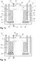
- FIG. 1a A synopsis of Figures 1a to 1b shows a humidifier 10 for a test chamber or a test room, not shown here, the humidifier 10 consisting of a container 11 with a container interior 12, in which a water bath 13 is accommodated, and a temperature control device 14, with a heating device 15 and a cooling device 16 for temperature control of the water bath 13 is formed.
- the humidifier 10 also includes an aeration device 17 for generating air bubbles 18 in the water bath 13.
- the heating device 15 comprises a heating coil 19 of a resistance heating element 20 , the heating coil 19 being positioned in the water bath 13 .
- the cooling device 16 has a cooling coil 21 which is formed from a tube 22 with a refrigerant circulating therein.
- the cooling coil 21 is also arranged inside the water bath 13 .
- the ventilation device 17 comprises two ventilation devices 23 and 24, which are spatially assigned to the heating device 15 and the cooling device 16, respectively.
- Each of the aerators 23 and 24 is made of a porous membrane 25 which is disc-shaped is formed, and a compressed air line 26 is formed.
- the compressed air lines 26 are each connected to a pump, not shown here, of the ventilation device 17 and can be supplied with compressed air separately from one another.
- the respective porous membranes 25 are arranged directly below the heating coil 19 or the cooling coil 21 relative to a water level 27 of the water bath 13 .
- a container opening 28 is formed above the water level 27, which merges into an air duct 29, which connects the container 11 to the test room, not shown here. Valves or similar devices are not provided in the air duct 29, so that the air duct 29 connects the container interior 12 to the test space in a substantially pressure-free manner.
- the humidifier 10 also includes a fill level sensor, not shown here, as well as an inlet valve 30 and an outlet valve 31. Water, in particular demineralized water, can be metered into the interior of the container 12 via the inlet valve 30, with water from the water bath 13 being drained from the interior of the container 12 using the outlet valve 31 can be. A height of the water level 27 can be kept essentially constant by dosing in the event of water loss as a result of evaporation. It is also possible to drain the water bath 13 completely, for example for maintenance purposes.
- the temperature control device 14 and the ventilation device 17 By controlling the temperature control device 14 and the ventilation device 17 with a control device of the humidifier 10 (not shown here), it is possible to set the temperature of the water bath 13 such that a dew point temperature of the saturated air can be set very precisely.
- An output of the humidifier 10 can optionally be very precisely regulated by regulating a delivery quantity of air via the pump of the ventilation device 17 in combination with the set dew point temperature.
- the heating device 15 with the ventilation device 23 can be switched off and the cooling device 16 with the ventilation device 24 can be switched on, so that the temperature of the water bath 13 and thus the dew point temperature of the air decrease.
- the humidifier 10 in the manner of an unpressurized steam humidifier.
- the water bath 13 can thus be heated by means of the heating coil 19 up to a boiling point of the water, in which case the steam thus generated can then be conducted via the air duct 29 to the test chamber.
- This output can be further increased if the pump of the aeration device 17 is activated during the boiling and air is blown into the water bath 13 via the aeration devices 23 or 24 .
- Such an increased degree of turbulence of the water bath 13 leads to a better expulsion of the steam generated from the container interior 12.
- the humidifier 10, with the control device not shown here, includes a test chamber control circuit, also not shown, and a humidifier control circuit with sensors for measuring temperature and/or relative humidity.
- the test chamber control circuit is coupled to the humidifier control circuit as part of a cascade control the test chamber control circuit is designed as a master controller and the humidifier control circuit is designed as a slave controller.
- an initial overheating of the water bath 13 can then also take place if a large quantity of saturated, warm air is to be introduced quickly into the test chamber.
- the test room can also be dehumidified via the control device by introducing very cold, saturated air into the test room. This air, which is then warmed up in the test space, can be enriched with water and discharged into an environment via a pressure relief valve in the test space, optionally also together with the pollutants of a test specimen located in the test space.
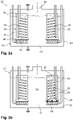
- a synopsis of Figures 2a to 2d 12 shows a further embodiment of a humidifier 32, the humidifier 32 being different from the humidifier 1 has a flow device 33 which is arranged on the heating coil 19 and the cooling coil 21 respectively.
- the flow device 33 forms a channel 34 with an upper end 35 and a lower end 36, each of which is open.
- the heating coil 19 and the cooling coil 21 are each arranged in the channel 34 .
- the channel 34 is formed here by a tube 37 which is widened at the lower end 36 .
- the upper end 35 projects beyond the water level 27 a little, for example a few centimeters.
- the water bath 13 is aerated with air bubbles 18 via the aerating device 24.
- the air bubbles 18 enter the channel 34 via the tube 37, which is widened at the lower end 26, so that the cooling coil 21 is intimately surrounded by air bubbles 18 flowing upward through the channel 34 . Consequently, the air bubbles 18 flow through a partial water quantity 38 of a total water quantity 39 of the water bath 13 in a targeted manner. This also leads to the raising of the water level 27 in the tube 37 compared to a Residual amount of water 40 of the water bath 13, which is not flowed through by air bubbles 18.
- the temperature of the partial amount of water 38 is controlled in the desired manner by means of the cooling coil 21, so that no temperature control of the total amount of water 39 is necessary here in order to generate saturated air with the desired dew point temperature. Since the partial amount of water 38 is many times smaller than the remaining amount of water 40 or the total amount of water 39, the partial amount of water 38 can also be tempered much faster than the total amount of water 39, so that with the help of the flow device 33 the humidifier 32 can be used in an energy-saving manner and with a possible dynamic temperature change during the balance the amount of air produced compared to the humidifier 1 can be operated.
- an amount of air in the aeration device 24 can also be increased to such an extent that the air bubbles 18 convey the water in the partial amount of water 38 beyond the upper end 35 of the pipe 37 and thus form a flow in the pipe 37 which mixes the partial amount of water 38 effected with the residual water quantity 40. If, for example, a temperature of the partial amount of water 38 is comparatively low and a temperature of the residual amount of water 40 is comparatively high, the two temperatures can be quickly equalized and thus a rapid temperature change in the partial amount of water 38 can be brought about. This makes it possible to generate air with dew point temperatures that differ significantly from one another within a few seconds using the humidifier 32 within the scope of a test interval.
- the Fig. 2d shows the humidifier 32 during operation of the ventilation devices 23 and 24, so that the residual water quantity 40 is completely mixed with the respective partial water quantities 38 here.
Landscapes
- Engineering & Computer Science (AREA)
- Chemical & Material Sciences (AREA)
- Combustion & Propulsion (AREA)
- Mechanical Engineering (AREA)
- General Engineering & Computer Science (AREA)
- Dispersion Chemistry (AREA)
- Testing Resistance To Weather, Investigating Materials By Mechanical Methods (AREA)
- Air Humidification (AREA)
Applications Claiming Priority (1)
| Application Number | Priority Date | Filing Date | Title |
|---|---|---|---|
| DE102017212412.1A DE102017212412A1 (de) | 2017-07-19 | 2017-07-19 | Befeuchter und Verfahren zur Konditionierung von Luft |
Publications (2)
| Publication Number | Publication Date |
|---|---|
| EP3431891A1 EP3431891A1 (de) | 2019-01-23 |
| EP3431891B1 true EP3431891B1 (de) | 2022-11-02 |
Family
ID=62814823
Family Applications (1)
| Application Number | Title | Priority Date | Filing Date |
|---|---|---|---|
| EP18180046.7A Active EP3431891B1 (de) | 2017-07-19 | 2018-06-27 | Befeuchter und verfahren zur konditionierung von luft |
Country Status (5)
| Country | Link |
|---|---|
| US (1) | US10876750B2 (enExample) |
| EP (1) | EP3431891B1 (enExample) |
| JP (1) | JP6791911B2 (enExample) |
| CN (1) | CN109282410B (enExample) |
| DE (1) | DE102017212412A1 (enExample) |
Cited By (1)
| Publication number | Priority date | Publication date | Assignee | Title |
|---|---|---|---|---|
| US20240060846A1 (en) * | 2022-04-28 | 2024-02-22 | Weiss Umwelttechnik Gmbh | Gas sensor and method for detecting gas |
Families Citing this family (9)
| Publication number | Priority date | Publication date | Assignee | Title |
|---|---|---|---|---|
| KR102053125B1 (ko) * | 2018-03-16 | 2020-01-08 | 엘지전자 주식회사 | 공기조화기의 실내기 |
| EP3767196A4 (en) * | 2018-03-16 | 2022-04-13 | LG Electronics Inc. | INDOOR UNIT FOR AN AIR CONDITIONER |
| CN112263144A (zh) * | 2020-10-23 | 2021-01-26 | 佛山市顺德区美的饮水机制造有限公司 | 用于饮水设备的方法、处理器、装置及饮水设备 |
| WO2022102667A1 (ja) * | 2020-11-10 | 2022-05-19 | 株式会社Zero Food | 蒸発加湿器 |
| CN112904907B (zh) * | 2021-01-18 | 2022-04-01 | 干将新材料有限公司 | 用于干燥剂产品检测的湿度控制装置 |
| JP7685760B2 (ja) * | 2022-05-10 | 2025-05-30 | 株式会社Zero Food | 冷蔵ショーケース及びネタケース |
| CN117389101A (zh) * | 2022-07-04 | 2024-01-12 | 中强光电股份有限公司 | 投影装置的散热模块与防结露方法 |
| KR20240158462A (ko) * | 2023-04-27 | 2024-11-05 | 엘지전자 주식회사 | 가습기 |
| CN116651533B (zh) * | 2023-05-26 | 2024-06-11 | 苏建桦 | 一种提高端粒长度之组合物的制备方法 |
Family Cites Families (35)
| Publication number | Priority date | Publication date | Assignee | Title |
|---|---|---|---|---|
| DE2134619B2 (de) * | 1971-07-10 | 1978-01-26 | Benteler Werke Ag, 4800 Bielefeld | Vorrichtung zur luftbefeuchtung und luftfilterung zum anbau an eine mit kastenartigem gehaeuse versehene heizeinheit |
| US3987133A (en) * | 1975-09-05 | 1976-10-19 | Fisher Scientific Company | Humidifier |
| JPS5268748A (en) | 1975-12-04 | 1977-06-07 | Kanto Seiki Co | Method of and apparatus for maintaining constant relative humidity |
| JPH0723790B2 (ja) * | 1982-06-10 | 1995-03-15 | 三洋電機株式会社 | 蒸気発生装置 |
| GB2173901B (en) * | 1985-04-01 | 1989-06-28 | Sharp Kk | Liquid storage means |
| DE3630886C1 (en) * | 1986-09-11 | 1987-12-10 | Heraeus Voetsch Gmbh | Climatic testing chamber with a cooling unit |
| US5799652A (en) * | 1995-05-22 | 1998-09-01 | Hypoxico Inc. | Hypoxic room system and equipment for Hypoxic training and therapy at standard atmospheric pressure |
| US6301433B1 (en) * | 2000-01-13 | 2001-10-09 | Sunbeam Products, Inc. | Humidifier with light |
| EP1370810B1 (en) * | 2001-03-20 | 2006-07-26 | AERMEC S.p.A. | Air-distribution cap for a convector |
| EP1384034A1 (en) | 2001-04-23 | 2004-01-28 | Drykor Ltd. | Apparatus for conditioning air |
| AUPR620701A0 (en) * | 2001-07-06 | 2001-08-02 | Ozone Manufacturing Pty Ltd | Evaporative cooler purifier |
| US6676271B2 (en) * | 2002-03-08 | 2004-01-13 | Sunbeam Products, Inc. | Humidifier with lighted tank |
| DE10259170A1 (de) | 2002-12-18 | 2004-07-08 | Klima Systemgesellschaft für Klimaprüftechnik und Umweltsimulation mbH & Co. KG | Befeuchtungseinheit sowie Verfahren zur aerosolfreien Befeuchtung mit hoher Regelgenauigkeit |
| JP2005118706A (ja) | 2003-10-17 | 2005-05-12 | Mitsubishi Electric Corp | 超音波凝集装置 |
| JP4291879B2 (ja) * | 2003-10-20 | 2009-07-08 | エスペック株式会社 | 飽和気体発生装置 |
| JP3815491B2 (ja) | 2004-06-30 | 2006-08-30 | ダイキン工業株式会社 | 熱交換器及び空気調和装置 |
| JP4539343B2 (ja) | 2005-01-21 | 2010-09-08 | スズキ株式会社 | 空気調和装置 |
| EP1894074A4 (en) | 2005-06-13 | 2010-05-19 | Sigma Systems Corp | METHODS AND APPARATUS FOR OPTIMIZING THE MOISTURE OF THE ENVIRONMENT |
| CN2874329Y (zh) * | 2005-11-28 | 2007-02-28 | 威海际高制冷空调设备有限公司 | 户式新风除湿机 |
| JP2007240141A (ja) | 2006-02-10 | 2007-09-20 | Haruo Tsuchimoto | 湿度制御方法、湿度制御装置及びそれを備える生ゴミ処理装置 |
| US7350773B2 (en) * | 2006-06-01 | 2008-04-01 | Sunbeam Products, Inc. | Vortex humidifier |
| US8116913B2 (en) * | 2008-09-16 | 2012-02-14 | Air Energy Solutions, Inc. | Heating and cooling system using compressed fluid |
| JP4502065B1 (ja) * | 2009-01-30 | 2010-07-14 | ダイキン工業株式会社 | ドレンレス空気調和装置 |
| CN202019592U (zh) * | 2011-03-24 | 2011-11-02 | 中国扬子集团滁州扬子空调器有限公司 | 一种植物工厂空气冷却除湿空调系统 |
| DE202011004938U1 (de) * | 2011-04-06 | 2011-06-09 | Radtke, Manfred R., 97209 | Vorrichtung zur Luftbe- und entfeuchtung mit Wasserflächen |
| US9072984B2 (en) | 2011-09-23 | 2015-07-07 | Massachusetts Institute Of Technology | Bubble-column vapor mixture condenser |
| EP3120083B1 (en) | 2014-03-20 | 2020-07-01 | 7AC Technologies, Inc. | Rooftop liquid desiccant systems and methods |
| JP2015183902A (ja) | 2014-03-24 | 2015-10-22 | パナソニックIpマネジメント株式会社 | 加湿装置 |
| CN204234107U (zh) | 2014-10-24 | 2015-04-01 | 伟思环境技术有限公司 | 试验箱 |
| CN104728957B (zh) | 2015-03-26 | 2018-01-02 | 苏州惠林节能材料有限公司 | 一种除湿/加湿装置及方法 |
| CN104764094B (zh) | 2015-03-26 | 2017-06-06 | 广东美的制冷设备有限公司 | 加湿空调器和加湿空调器的控制方法 |
| CN105605687A (zh) | 2015-12-22 | 2016-05-25 | 凯天环保科技股份有限公司 | 空气净化器 |
| CN205783455U (zh) * | 2015-12-31 | 2016-12-07 | 宁波惠康实业有限公司 | 双冷源双热源恒温恒湿空调机组 |
| CN205641664U (zh) | 2016-04-22 | 2016-10-12 | 广东美的制冷设备有限公司 | 空调系统及具有其的空调器 |
| CN206281090U (zh) | 2016-09-05 | 2017-06-27 | 青岛海尔智能技术研发有限公司 | 除湿机 |
-
2017
- 2017-07-19 DE DE102017212412.1A patent/DE102017212412A1/de not_active Ceased
-
2018
- 2018-06-27 EP EP18180046.7A patent/EP3431891B1/de active Active
- 2018-07-16 US US16/035,894 patent/US10876750B2/en active Active
- 2018-07-17 JP JP2018134011A patent/JP6791911B2/ja not_active Expired - Fee Related
- 2018-07-19 CN CN201810795164.6A patent/CN109282410B/zh active Active
Cited By (1)
| Publication number | Priority date | Publication date | Assignee | Title |
|---|---|---|---|---|
| US20240060846A1 (en) * | 2022-04-28 | 2024-02-22 | Weiss Umwelttechnik Gmbh | Gas sensor and method for detecting gas |
Also Published As
| Publication number | Publication date |
|---|---|
| US10876750B2 (en) | 2020-12-29 |
| CN109282410A (zh) | 2019-01-29 |
| JP2019023555A (ja) | 2019-02-14 |
| JP6791911B2 (ja) | 2020-11-25 |
| EP3431891A1 (de) | 2019-01-23 |
| DE102017212412A1 (de) | 2019-01-24 |
| US20190137127A1 (en) | 2019-05-09 |
| CN109282410B (zh) | 2021-01-08 |
Similar Documents
| Publication | Publication Date | Title |
|---|---|---|
| EP3431891B1 (de) | Befeuchter und verfahren zur konditionierung von luft | |
| CH706146A2 (de) | Verfahren und System zum Temperieren von Bauteilen. | |
| DE102005018142B4 (de) | Klimakammer zur schnellen Erreichung und Aufrechterhaltung einer vorgegebenen Luftfeuchtigkeit und/oder einer vorgegebenen Temperatur | |
| DE1949001C3 (de) | Verfahren und Einrichtung zur Regelung der Luftfeuchte in einer Pflanzenwuchskammer | |
| EP3809116B1 (de) | Prüfkammer und verfahren zur konditionierung von luft | |
| EP3076106B1 (de) | Kühleinheit | |
| EP1710516B1 (de) | Vorrichtung und Verfahren zur Befeuchtung eines Luftstromes | |
| CH709751A2 (de) | Kühlgerät mit einem Nutzraum mit mehreren Temperaturzonen. | |
| EP3601902B1 (de) | Kältegerät und betriebsverfahren dafür | |
| WO2010020220A1 (de) | Vorrichtung zur luftbefeuchtung | |
| AT411794B (de) | Wärmeübertragereinheit mit strahlpumpe als stellorgan | |
| DE202017104462U1 (de) | Wärmetauscheranordnung | |
| EP3696468A1 (de) | Membranelement für einen luftbefeuchtungsvorrichtung und verfahren zur herstellung eines membranelementes | |
| DE202007013484U1 (de) | Dampfbefeuchter | |
| EP3194855B1 (de) | Vorrichtung und verfahren zur konditionierung eines gasstromes | |
| DE1698104B1 (de) | Klimamess- und -pruefschrank | |
| DE2153175C3 (de) | Anlage zum Temperieren und Entfeuchten eines Luftstromes zur Klimatisierung von Räumen | |
| EP1703220B1 (de) | Einrichtung zum Befeuchten von Prozeßluft | |
| DD256286A5 (de) | Vorrichtung zum einstellen der temperatur von geraeten, insb. werkzeugen | |
| EP4460665B1 (de) | Anordnung zum erwärmen einer flüssigkeit | |
| DE102012106994B4 (de) | System von Bodenplatten für ein Doppelbodensystem und ein Doppelbodensystem | |
| DE102021103231B4 (de) | Gewerbliche Geschirrspülmaschine und Verfahren zum Betreiben einer solchen | |
| EP2708811A1 (de) | Verfahren zum Einstellen der Luftfeuchte in einem geschlossenen Raum | |
| DE102013012080A1 (de) | Heizsystem und Betriebsverfahren dafür | |
| CH315528A (de) | Einrichtung zur Beeinflussung des klimatischen Zustandes in einem Raum |
Legal Events
| Date | Code | Title | Description |
|---|---|---|---|
| PUAI | Public reference made under article 153(3) epc to a published international application that has entered the european phase |
Free format text: ORIGINAL CODE: 0009012 |
|
| STAA | Information on the status of an ep patent application or granted ep patent |
Free format text: STATUS: THE APPLICATION HAS BEEN PUBLISHED |
|
| AK | Designated contracting states |
Kind code of ref document: A1 Designated state(s): AL AT BE BG CH CY CZ DE DK EE ES FI FR GB GR HR HU IE IS IT LI LT LU LV MC MK MT NL NO PL PT RO RS SE SI SK SM TR |
|
| AX | Request for extension of the european patent |
Extension state: BA ME |
|
| STAA | Information on the status of an ep patent application or granted ep patent |
Free format text: STATUS: REQUEST FOR EXAMINATION WAS MADE |
|
| 17P | Request for examination filed |
Effective date: 20190704 |
|
| RBV | Designated contracting states (corrected) |
Designated state(s): AL AT BE BG CH CY CZ DE DK EE ES FI FR GB GR HR HU IE IS IT LI LT LU LV MC MK MT NL NO PL PT RO RS SE SI SK SM TR |
|
| STAA | Information on the status of an ep patent application or granted ep patent |
Free format text: STATUS: EXAMINATION IS IN PROGRESS |
|
| 17Q | First examination report despatched |
Effective date: 20201102 |
|
| REG | Reference to a national code |
Ref country code: DE Ref legal event code: R079 Ref document number: 502018010945 Country of ref document: DE Free format text: PREVIOUS MAIN CLASS: F24F0009000000 Ipc: F24F0006020000 |
|
| RIC1 | Information provided on ipc code assigned before grant |
Ipc: G01N 17/00 20060101ALI20220412BHEP Ipc: F24F 3/14 20060101ALI20220412BHEP Ipc: F24F 6/02 20060101AFI20220412BHEP |
|
| GRAP | Despatch of communication of intention to grant a patent |
Free format text: ORIGINAL CODE: EPIDOSNIGR1 |
|
| STAA | Information on the status of an ep patent application or granted ep patent |
Free format text: STATUS: GRANT OF PATENT IS INTENDED |
|
| INTG | Intention to grant announced |
Effective date: 20220520 |
|
| RIN1 | Information on inventor provided before grant (corrected) |
Inventor name: SALAMON, BOJAN Inventor name: TEICHMANN, JOHANNES Inventor name: BITZER, JUERGEN Inventor name: SCHLOSSER, VOLKER Inventor name: HAACK, CHRISTIAN |
|
| GRAS | Grant fee paid |
Free format text: ORIGINAL CODE: EPIDOSNIGR3 |
|
| GRAA | (expected) grant |
Free format text: ORIGINAL CODE: 0009210 |
|
| STAA | Information on the status of an ep patent application or granted ep patent |
Free format text: STATUS: THE PATENT HAS BEEN GRANTED |
|
| RAP3 | Party data changed (applicant data changed or rights of an application transferred) |
Owner name: WEISS TECHNIK GMBH |
|
| RIN1 | Information on inventor provided before grant (corrected) |
Inventor name: SALAMON, BOJAN Inventor name: TEICHMANN, JOHANNES Inventor name: BITZER, JUERGEN Inventor name: SCHLOSSER, VOLKER Inventor name: HAACK, CHRISTIAN |
|
| AK | Designated contracting states |
Kind code of ref document: B1 Designated state(s): AL AT BE BG CH CY CZ DE DK EE ES FI FR GB GR HR HU IE IS IT LI LT LU LV MC MK MT NL NO PL PT RO RS SE SI SK SM TR |
|
| REG | Reference to a national code |
Ref country code: GB Ref legal event code: FG4D Free format text: NOT ENGLISH |
|
| REG | Reference to a national code |
Ref country code: CH Ref legal event code: EP Ref country code: AT Ref legal event code: REF Ref document number: 1529003 Country of ref document: AT Kind code of ref document: T Effective date: 20221115 |
|
| REG | Reference to a national code |
Ref country code: DE Ref legal event code: R096 Ref document number: 502018010945 Country of ref document: DE |
|
| REG | Reference to a national code |
Ref country code: IE Ref legal event code: FG4D Free format text: LANGUAGE OF EP DOCUMENT: GERMAN |
|
| REG | Reference to a national code |
Ref country code: LT Ref legal event code: MG9D |
|
| REG | Reference to a national code |
Ref country code: NL Ref legal event code: MP Effective date: 20221102 |
|
| PG25 | Lapsed in a contracting state [announced via postgrant information from national office to epo] |
Ref country code: SE Free format text: LAPSE BECAUSE OF FAILURE TO SUBMIT A TRANSLATION OF THE DESCRIPTION OR TO PAY THE FEE WITHIN THE PRESCRIBED TIME-LIMIT Effective date: 20221102 Ref country code: PT Free format text: LAPSE BECAUSE OF FAILURE TO SUBMIT A TRANSLATION OF THE DESCRIPTION OR TO PAY THE FEE WITHIN THE PRESCRIBED TIME-LIMIT Effective date: 20230302 Ref country code: NO Free format text: LAPSE BECAUSE OF FAILURE TO SUBMIT A TRANSLATION OF THE DESCRIPTION OR TO PAY THE FEE WITHIN THE PRESCRIBED TIME-LIMIT Effective date: 20230202 Ref country code: LT Free format text: LAPSE BECAUSE OF FAILURE TO SUBMIT A TRANSLATION OF THE DESCRIPTION OR TO PAY THE FEE WITHIN THE PRESCRIBED TIME-LIMIT Effective date: 20221102 Ref country code: FI Free format text: LAPSE BECAUSE OF FAILURE TO SUBMIT A TRANSLATION OF THE DESCRIPTION OR TO PAY THE FEE WITHIN THE PRESCRIBED TIME-LIMIT Effective date: 20221102 Ref country code: ES Free format text: LAPSE BECAUSE OF FAILURE TO SUBMIT A TRANSLATION OF THE DESCRIPTION OR TO PAY THE FEE WITHIN THE PRESCRIBED TIME-LIMIT Effective date: 20221102 |
|
| PG25 | Lapsed in a contracting state [announced via postgrant information from national office to epo] |
Ref country code: RS Free format text: LAPSE BECAUSE OF FAILURE TO SUBMIT A TRANSLATION OF THE DESCRIPTION OR TO PAY THE FEE WITHIN THE PRESCRIBED TIME-LIMIT Effective date: 20221102 Ref country code: PL Free format text: LAPSE BECAUSE OF FAILURE TO SUBMIT A TRANSLATION OF THE DESCRIPTION OR TO PAY THE FEE WITHIN THE PRESCRIBED TIME-LIMIT Effective date: 20221102 Ref country code: LV Free format text: LAPSE BECAUSE OF FAILURE TO SUBMIT A TRANSLATION OF THE DESCRIPTION OR TO PAY THE FEE WITHIN THE PRESCRIBED TIME-LIMIT Effective date: 20221102 Ref country code: IS Free format text: LAPSE BECAUSE OF FAILURE TO SUBMIT A TRANSLATION OF THE DESCRIPTION OR TO PAY THE FEE WITHIN THE PRESCRIBED TIME-LIMIT Effective date: 20230302 Ref country code: HR Free format text: LAPSE BECAUSE OF FAILURE TO SUBMIT A TRANSLATION OF THE DESCRIPTION OR TO PAY THE FEE WITHIN THE PRESCRIBED TIME-LIMIT Effective date: 20221102 Ref country code: GR Free format text: LAPSE BECAUSE OF FAILURE TO SUBMIT A TRANSLATION OF THE DESCRIPTION OR TO PAY THE FEE WITHIN THE PRESCRIBED TIME-LIMIT Effective date: 20230203 |
|
| P01 | Opt-out of the competence of the unified patent court (upc) registered |
Effective date: 20230524 |
|
| PG25 | Lapsed in a contracting state [announced via postgrant information from national office to epo] |
Ref country code: NL Free format text: LAPSE BECAUSE OF FAILURE TO SUBMIT A TRANSLATION OF THE DESCRIPTION OR TO PAY THE FEE WITHIN THE PRESCRIBED TIME-LIMIT Effective date: 20221102 |
|
| PG25 | Lapsed in a contracting state [announced via postgrant information from national office to epo] |
Ref country code: SM Free format text: LAPSE BECAUSE OF FAILURE TO SUBMIT A TRANSLATION OF THE DESCRIPTION OR TO PAY THE FEE WITHIN THE PRESCRIBED TIME-LIMIT Effective date: 20221102 Ref country code: RO Free format text: LAPSE BECAUSE OF FAILURE TO SUBMIT A TRANSLATION OF THE DESCRIPTION OR TO PAY THE FEE WITHIN THE PRESCRIBED TIME-LIMIT Effective date: 20221102 Ref country code: EE Free format text: LAPSE BECAUSE OF FAILURE TO SUBMIT A TRANSLATION OF THE DESCRIPTION OR TO PAY THE FEE WITHIN THE PRESCRIBED TIME-LIMIT Effective date: 20221102 Ref country code: DK Free format text: LAPSE BECAUSE OF FAILURE TO SUBMIT A TRANSLATION OF THE DESCRIPTION OR TO PAY THE FEE WITHIN THE PRESCRIBED TIME-LIMIT Effective date: 20221102 Ref country code: CZ Free format text: LAPSE BECAUSE OF FAILURE TO SUBMIT A TRANSLATION OF THE DESCRIPTION OR TO PAY THE FEE WITHIN THE PRESCRIBED TIME-LIMIT Effective date: 20221102 |
|
| REG | Reference to a national code |
Ref country code: DE Ref legal event code: R097 Ref document number: 502018010945 Country of ref document: DE |
|
| PG25 | Lapsed in a contracting state [announced via postgrant information from national office to epo] |
Ref country code: SK Free format text: LAPSE BECAUSE OF FAILURE TO SUBMIT A TRANSLATION OF THE DESCRIPTION OR TO PAY THE FEE WITHIN THE PRESCRIBED TIME-LIMIT Effective date: 20221102 Ref country code: AL Free format text: LAPSE BECAUSE OF FAILURE TO SUBMIT A TRANSLATION OF THE DESCRIPTION OR TO PAY THE FEE WITHIN THE PRESCRIBED TIME-LIMIT Effective date: 20221102 |
|
| PLBE | No opposition filed within time limit |
Free format text: ORIGINAL CODE: 0009261 |
|
| STAA | Information on the status of an ep patent application or granted ep patent |
Free format text: STATUS: NO OPPOSITION FILED WITHIN TIME LIMIT |
|
| 26N | No opposition filed |
Effective date: 20230803 |
|
| PGFP | Annual fee paid to national office [announced via postgrant information from national office to epo] |
Ref country code: GB Payment date: 20230620 Year of fee payment: 6 |
|
| PG25 | Lapsed in a contracting state [announced via postgrant information from national office to epo] |
Ref country code: SI Free format text: LAPSE BECAUSE OF FAILURE TO SUBMIT A TRANSLATION OF THE DESCRIPTION OR TO PAY THE FEE WITHIN THE PRESCRIBED TIME-LIMIT Effective date: 20221102 |
|
| PG25 | Lapsed in a contracting state [announced via postgrant information from national office to epo] |
Ref country code: MC Free format text: LAPSE BECAUSE OF FAILURE TO SUBMIT A TRANSLATION OF THE DESCRIPTION OR TO PAY THE FEE WITHIN THE PRESCRIBED TIME-LIMIT Effective date: 20221102 |
|
| PG25 | Lapsed in a contracting state [announced via postgrant information from national office to epo] |
Ref country code: MC Free format text: LAPSE BECAUSE OF FAILURE TO SUBMIT A TRANSLATION OF THE DESCRIPTION OR TO PAY THE FEE WITHIN THE PRESCRIBED TIME-LIMIT Effective date: 20221102 |
|
| REG | Reference to a national code |
Ref country code: CH Ref legal event code: PL |
|
| REG | Reference to a national code |
Ref country code: BE Ref legal event code: MM Effective date: 20230630 |
|
| PG25 | Lapsed in a contracting state [announced via postgrant information from national office to epo] |
Ref country code: LU Free format text: LAPSE BECAUSE OF NON-PAYMENT OF DUE FEES Effective date: 20230627 |
|
| REG | Reference to a national code |
Ref country code: IE Ref legal event code: MM4A |
|
| PG25 | Lapsed in a contracting state [announced via postgrant information from national office to epo] |
Ref country code: LU Free format text: LAPSE BECAUSE OF NON-PAYMENT OF DUE FEES Effective date: 20230627 |
|
| PG25 | Lapsed in a contracting state [announced via postgrant information from national office to epo] |
Ref country code: IE Free format text: LAPSE BECAUSE OF NON-PAYMENT OF DUE FEES Effective date: 20230627 |
|
| PG25 | Lapsed in a contracting state [announced via postgrant information from national office to epo] |
Ref country code: IE Free format text: LAPSE BECAUSE OF NON-PAYMENT OF DUE FEES Effective date: 20230627 Ref country code: CH Free format text: LAPSE BECAUSE OF NON-PAYMENT OF DUE FEES Effective date: 20230630 |
|
| PG25 | Lapsed in a contracting state [announced via postgrant information from national office to epo] |
Ref country code: BE Free format text: LAPSE BECAUSE OF NON-PAYMENT OF DUE FEES Effective date: 20230630 |
|
| REG | Reference to a national code |
Ref country code: AT Ref legal event code: MM01 Ref document number: 1529003 Country of ref document: AT Kind code of ref document: T Effective date: 20230627 |
|
| PG25 | Lapsed in a contracting state [announced via postgrant information from national office to epo] |
Ref country code: AT Free format text: LAPSE BECAUSE OF NON-PAYMENT OF DUE FEES Effective date: 20230627 |
|
| PG25 | Lapsed in a contracting state [announced via postgrant information from national office to epo] |
Ref country code: AT Free format text: LAPSE BECAUSE OF NON-PAYMENT OF DUE FEES Effective date: 20230627 |
|
| PG25 | Lapsed in a contracting state [announced via postgrant information from national office to epo] |
Ref country code: BG Free format text: LAPSE BECAUSE OF FAILURE TO SUBMIT A TRANSLATION OF THE DESCRIPTION OR TO PAY THE FEE WITHIN THE PRESCRIBED TIME-LIMIT Effective date: 20221102 |
|
| PG25 | Lapsed in a contracting state [announced via postgrant information from national office to epo] |
Ref country code: BG Free format text: LAPSE BECAUSE OF FAILURE TO SUBMIT A TRANSLATION OF THE DESCRIPTION OR TO PAY THE FEE WITHIN THE PRESCRIBED TIME-LIMIT Effective date: 20221102 |
|
| GBPC | Gb: european patent ceased through non-payment of renewal fee |
Effective date: 20240627 |
|
| PG25 | Lapsed in a contracting state [announced via postgrant information from national office to epo] |
Ref country code: GB Free format text: LAPSE BECAUSE OF NON-PAYMENT OF DUE FEES Effective date: 20240627 |
|
| PGFP | Annual fee paid to national office [announced via postgrant information from national office to epo] |
Ref country code: DE Payment date: 20250626 Year of fee payment: 8 |
|
| REG | Reference to a national code |
Ref country code: DE Ref legal event code: R081 Ref document number: 502018010945 Country of ref document: DE Owner name: WEISS-VOETSCH ENVIRONMENTAL TESTING INSTRUMENT, CN Free format text: FORMER OWNER: WEISS TECHNIK GMBH, 35447 REISKIRCHEN, DE |
|
| PGFP | Annual fee paid to national office [announced via postgrant information from national office to epo] |
Ref country code: FR Payment date: 20250624 Year of fee payment: 8 |
|
| PG25 | Lapsed in a contracting state [announced via postgrant information from national office to epo] |
Ref country code: CY Free format text: LAPSE BECAUSE OF FAILURE TO SUBMIT A TRANSLATION OF THE DESCRIPTION OR TO PAY THE FEE WITHIN THE PRESCRIBED TIME-LIMIT; INVALID AB INITIO Effective date: 20180627 |
|
| PG25 | Lapsed in a contracting state [announced via postgrant information from national office to epo] |
Ref country code: HU Free format text: LAPSE BECAUSE OF FAILURE TO SUBMIT A TRANSLATION OF THE DESCRIPTION OR TO PAY THE FEE WITHIN THE PRESCRIBED TIME-LIMIT; INVALID AB INITIO Effective date: 20180627 |
|
| PGFP | Annual fee paid to national office [announced via postgrant information from national office to epo] |
Ref country code: IT Payment date: 20250623 Year of fee payment: 8 |
|
| PG25 | Lapsed in a contracting state [announced via postgrant information from national office to epo] |
Ref country code: TR Free format text: LAPSE BECAUSE OF FAILURE TO SUBMIT A TRANSLATION OF THE DESCRIPTION OR TO PAY THE FEE WITHIN THE PRESCRIBED TIME-LIMIT Effective date: 20221102 |