EP3431891B1 - Humidifier and method for conditioning of air - Google Patents
Humidifier and method for conditioning of air Download PDFInfo
- Publication number
- EP3431891B1 EP3431891B1 EP18180046.7A EP18180046A EP3431891B1 EP 3431891 B1 EP3431891 B1 EP 3431891B1 EP 18180046 A EP18180046 A EP 18180046A EP 3431891 B1 EP3431891 B1 EP 3431891B1
- Authority
- EP
- European Patent Office
- Prior art keywords
- humidifier
- water
- temperature
- air
- water bath
- Prior art date
- Legal status (The legal status is an assumption and is not a legal conclusion. Google has not performed a legal analysis and makes no representation as to the accuracy of the status listed.)
- Active
Links
- 238000000034 method Methods 0.000 title claims description 25
- 230000003750 conditioning effect Effects 0.000 title claims description 7
- XLYOFNOQVPJJNP-UHFFFAOYSA-N water Substances O XLYOFNOQVPJJNP-UHFFFAOYSA-N 0.000 claims description 238
- 238000012360 testing method Methods 0.000 claims description 166
- 238000001816 cooling Methods 0.000 claims description 52
- 238000010438 heat treatment Methods 0.000 claims description 52
- 238000009423 ventilation Methods 0.000 claims description 44
- 239000012528 membrane Substances 0.000 claims description 14
- 238000009835 boiling Methods 0.000 claims description 5
- 239000000463 material Substances 0.000 claims description 5
- 239000000443 aerosol Substances 0.000 claims description 2
- 229920006395 saturated elastomer Polymers 0.000 description 16
- 238000005273 aeration Methods 0.000 description 14
- 230000008859 change Effects 0.000 description 7
- 238000007791 dehumidification Methods 0.000 description 5
- 230000001105 regulatory effect Effects 0.000 description 5
- 239000003344 environmental pollutant Substances 0.000 description 4
- 231100000719 pollutant Toxicity 0.000 description 4
- 238000005276 aerator Methods 0.000 description 3
- 230000009467 reduction Effects 0.000 description 3
- 230000002123 temporal effect Effects 0.000 description 3
- 238000012546 transfer Methods 0.000 description 3
- 238000009833 condensation Methods 0.000 description 2
- 230000005494 condensation Effects 0.000 description 2
- 230000001276 controlling effect Effects 0.000 description 2
- 230000001419 dependent effect Effects 0.000 description 2
- 238000013461 design Methods 0.000 description 2
- 238000001704 evaporation Methods 0.000 description 2
- 230000008020 evaporation Effects 0.000 description 2
- 238000007710 freezing Methods 0.000 description 2
- 230000008014 freezing Effects 0.000 description 2
- 239000003507 refrigerant Substances 0.000 description 2
- 230000004044 response Effects 0.000 description 2
- 241000270295 Serpentes Species 0.000 description 1
- 238000004378 air conditioning Methods 0.000 description 1
- 230000000712 assembly Effects 0.000 description 1
- 238000000429 assembly Methods 0.000 description 1
- 230000015572 biosynthetic process Effects 0.000 description 1
- 229910010293 ceramic material Inorganic materials 0.000 description 1
- 238000004140 cleaning Methods 0.000 description 1
- 230000001143 conditioned effect Effects 0.000 description 1
- 238000005260 corrosion Methods 0.000 description 1
- 230000007797 corrosion Effects 0.000 description 1
- 230000000694 effects Effects 0.000 description 1
- 238000005485 electric heating Methods 0.000 description 1
- 238000005562 fading Methods 0.000 description 1
- 239000006260 foam Substances 0.000 description 1
- 239000007788 liquid Substances 0.000 description 1
- 238000012423 maintenance Methods 0.000 description 1
- 238000013021 overheating Methods 0.000 description 1
- 230000008569 process Effects 0.000 description 1
- 230000000630 rising effect Effects 0.000 description 1
- 239000000126 substance Substances 0.000 description 1
Images

Classifications
-
- F—MECHANICAL ENGINEERING; LIGHTING; HEATING; WEAPONS; BLASTING
- F24—HEATING; RANGES; VENTILATING
- F24F—AIR-CONDITIONING; AIR-HUMIDIFICATION; VENTILATION; USE OF AIR CURRENTS FOR SCREENING
- F24F6/00—Air-humidification, e.g. cooling by humidification
- F24F6/02—Air-humidification, e.g. cooling by humidification by evaporation of water in the air
- F24F6/08—Air-humidification, e.g. cooling by humidification by evaporation of water in the air using heated wet elements
- F24F6/10—Air-humidification, e.g. cooling by humidification by evaporation of water in the air using heated wet elements heated electrically
-
- F—MECHANICAL ENGINEERING; LIGHTING; HEATING; WEAPONS; BLASTING
- F24—HEATING; RANGES; VENTILATING
- F24F—AIR-CONDITIONING; AIR-HUMIDIFICATION; VENTILATION; USE OF AIR CURRENTS FOR SCREENING
- F24F11/00—Control or safety arrangements
- F24F11/0008—Control or safety arrangements for air-humidification
-
- F—MECHANICAL ENGINEERING; LIGHTING; HEATING; WEAPONS; BLASTING
- F24—HEATING; RANGES; VENTILATING
- F24F—AIR-CONDITIONING; AIR-HUMIDIFICATION; VENTILATION; USE OF AIR CURRENTS FOR SCREENING
- F24F6/00—Air-humidification, e.g. cooling by humidification
- F24F6/02—Air-humidification, e.g. cooling by humidification by evaporation of water in the air
- F24F6/025—Air-humidification, e.g. cooling by humidification by evaporation of water in the air using electrical heating means
-
- F—MECHANICAL ENGINEERING; LIGHTING; HEATING; WEAPONS; BLASTING
- F24—HEATING; RANGES; VENTILATING
- F24F—AIR-CONDITIONING; AIR-HUMIDIFICATION; VENTILATION; USE OF AIR CURRENTS FOR SCREENING
- F24F11/00—Control or safety arrangements
- F24F11/89—Arrangement or mounting of control or safety devices
-
- F—MECHANICAL ENGINEERING; LIGHTING; HEATING; WEAPONS; BLASTING
- F24—HEATING; RANGES; VENTILATING
- F24F—AIR-CONDITIONING; AIR-HUMIDIFICATION; VENTILATION; USE OF AIR CURRENTS FOR SCREENING
- F24F6/00—Air-humidification, e.g. cooling by humidification
- F24F6/12—Air-humidification, e.g. cooling by humidification by forming water dispersions in the air
-
- F—MECHANICAL ENGINEERING; LIGHTING; HEATING; WEAPONS; BLASTING
- F24—HEATING; RANGES; VENTILATING
- F24F—AIR-CONDITIONING; AIR-HUMIDIFICATION; VENTILATION; USE OF AIR CURRENTS FOR SCREENING
- F24F3/00—Air-conditioning systems in which conditioned primary air is supplied from one or more central stations to distributing units in the rooms or spaces where it may receive secondary treatment; Apparatus specially designed for such systems
- F24F3/12—Air-conditioning systems in which conditioned primary air is supplied from one or more central stations to distributing units in the rooms or spaces where it may receive secondary treatment; Apparatus specially designed for such systems characterised by the treatment of the air otherwise than by heating and cooling
- F24F3/14—Air-conditioning systems in which conditioned primary air is supplied from one or more central stations to distributing units in the rooms or spaces where it may receive secondary treatment; Apparatus specially designed for such systems characterised by the treatment of the air otherwise than by heating and cooling by humidification; by dehumidification
- F24F2003/144—Air-conditioning systems in which conditioned primary air is supplied from one or more central stations to distributing units in the rooms or spaces where it may receive secondary treatment; Apparatus specially designed for such systems characterised by the treatment of the air otherwise than by heating and cooling by humidification; by dehumidification by dehumidification only
- F24F2003/1446—Air-conditioning systems in which conditioned primary air is supplied from one or more central stations to distributing units in the rooms or spaces where it may receive secondary treatment; Apparatus specially designed for such systems characterised by the treatment of the air otherwise than by heating and cooling by humidification; by dehumidification by dehumidification only by condensing
-
- F—MECHANICAL ENGINEERING; LIGHTING; HEATING; WEAPONS; BLASTING
- F24—HEATING; RANGES; VENTILATING
- F24F—AIR-CONDITIONING; AIR-HUMIDIFICATION; VENTILATION; USE OF AIR CURRENTS FOR SCREENING
- F24F6/00—Air-humidification, e.g. cooling by humidification
- F24F2006/006—Air-humidification, e.g. cooling by humidification with water treatment
-
- F—MECHANICAL ENGINEERING; LIGHTING; HEATING; WEAPONS; BLASTING
- F24—HEATING; RANGES; VENTILATING
- F24F—AIR-CONDITIONING; AIR-HUMIDIFICATION; VENTILATION; USE OF AIR CURRENTS FOR SCREENING
- F24F6/00—Air-humidification, e.g. cooling by humidification
- F24F2006/008—Air-humidifier with water reservoir
-
- F—MECHANICAL ENGINEERING; LIGHTING; HEATING; WEAPONS; BLASTING
- F24—HEATING; RANGES; VENTILATING
- F24F—AIR-CONDITIONING; AIR-HUMIDIFICATION; VENTILATION; USE OF AIR CURRENTS FOR SCREENING
- F24F2110/00—Control inputs relating to air properties
- F24F2110/10—Temperature
-
- F—MECHANICAL ENGINEERING; LIGHTING; HEATING; WEAPONS; BLASTING
- F24—HEATING; RANGES; VENTILATING
- F24F—AIR-CONDITIONING; AIR-HUMIDIFICATION; VENTILATION; USE OF AIR CURRENTS FOR SCREENING
- F24F2110/00—Control inputs relating to air properties
- F24F2110/20—Humidity
-
- G—PHYSICS
- G01—MEASURING; TESTING
- G01N—INVESTIGATING OR ANALYSING MATERIALS BY DETERMINING THEIR CHEMICAL OR PHYSICAL PROPERTIES
- G01N17/00—Investigating resistance of materials to the weather, to corrosion, or to light
- G01N17/002—Test chambers
Definitions
- the invention relates to a humidifier for a test chamber, a test chamber and a method for conditioning the air in a test space of a test chamber, in particular a climatic chamber or the like, the humidifier comprising a container with an interior space for accommodating a water bath, a heating device of a temperature control device for temperature control of the water bath, and an aeration device for generating air bubbles in the water bath, a container opening for connecting the interior of the container to a test space of a test chamber being formed above the water bath in the container.
- Test chambers are regularly used to check the physical and/or chemical properties of objects, especially devices.
- temperature test cabinets or climate test cabinets are known within which temperatures can be set in a range from -50°C to +180°C.
- additional desired climatic conditions can be set, which then the device or the test material via a defined period of time is suspended.
- Such test chambers are regularly or partially designed as a mobile device, which is only connected to a building with the necessary supply lines and includes all the assemblies required for temperature control and air conditioning. Temperature control of a test room accommodating the test material to be tested is regularly carried out in a circulating air duct within the test room.
- One or more heat exchangers for heating or cooling the air flowing through the circulating air duct or the test chamber are arranged in the circulating air duct.
- a fan sucks in the air in the test room and directs it to the respective heat exchangers in the circulating air duct.
- the test material can be tempered in this way or exposed to a defined temperature change. During a test interval, for example, a temperature can then change between a maximum temperature and a minimum temperature of the test chamber.
- a humidifier built into the climate test cabinet is used.
- humidifiers are known here that are designed inside the test space in the manner of a trough-like depression in a floor of the test space.
- the trough-like depression then has a heating element with which the water filled into the depression can be heated or evaporated.
- a drain can also be provided in the trough-like depression, via which the water can be drained if necessary.
- the disadvantage here is that the water located within the test chamber can absorb pollutants from test specimens, which in turn can lead to corrosion of components of the humidifier, such as a heating element.
- the water can not during a test cycle, but only then be let out of the test room so as not to influence the test cycle.
- an influencing of a test cycle due to the water at least to a small extent, cannot be avoided even when the humidifier function is switched off.
- test cycles with temperature changes to below freezing point require the water in the tub to be drained.
- This type of humidifier is comparatively expensive to produce, since humidifiers that are appropriately adapted to different test chamber sizes always have to be constructed in the floor of the relevant test room.
- the DE 10 259 170 A1 proposes a humidifier formed of a container filled with a water bath separated from a test room. Inside the water bath there is a temperature control device for heating the water bath and below the temperature control device a so-called aerator for generating air bubbles in the water bath.
- a temperature control device for heating the water bath
- a so-called aerator for generating air bubbles in the water bath.
- it is intended to temper the water bath at a temperature of 50 °C to 80 °C and to introduce air into the test room, which rises in the form of air bubbles in the water bath.
- the air is aerosol-free, so that the test room is not humidified with steam. It is particularly advantageous here that no water bath has to be provided in the test room and that the water bath cannot be contaminated with, for example, pollutants.
- the DE 102 59 170 A1 thus discloses a humidifier having the features of the preamble of claim 1 and a method having the features of the preamble
- the disadvantage of the known humidifier is that humidification can only be regulated very sluggishly due to the amount of water in the container. A high level of humidity constancy or a rapid change in air temperature or relative humidity in the test room within the scope of a test interval can therefore not be achieved with the humidifier. A drop in the air temperature in the test room also requires the air in the test room to be dehumidified, for example with a dehumidifier.
- the US 3,987,133A describes a humidifier with a heater, which can supply a test chamber with humidified air.
- the heater is inside the liquid medium.
- U1 is a device for air humidification and air dehumidification using water surfaces.
- a jet of water is tempered warm or cold so that the air touching it is humidified (warm water) or dehumidified (cold water).
- the water is heated or cooled by a temperature control device.
- JP S58 217134 A relates to a heatable water bath.
- the present invention is therefore based on the object of proposing a humidifier for a test chamber and a method for conditioning the air in a test chamber of a test chamber, which enables a high degree of constancy of relative humidity in a test chamber even under rapidly changing test conditions.
- the humidifier according to the invention for a test chamber in particular a climatic chamber, has a container with a container interior for accommodating a water bath, a heating device of a temperature control device for temperature control of the water bath, and an aeration device for generating air bubbles in the water bath, with a Container opening for connecting the container interior is formed with a test space of a test chamber, wherein the humidifier has a cooling device of the temperature control device, wherein the heating device and the Cooling device are each formed with a heat exchanger arranged in the water bath.
- the tank of the humidifier is essentially closed and temperature-insulated and the heater is arranged in the water bath so that the water bath can be heated by the heater.
- the container opening is used for a tight connection to a test room, so that humidified air from the container can be introduced into a test room via an air duct or hose, for example.
- the humidifier can be designed in a modular manner independently of the size of a test chamber or a test room. It is also then no longer necessary to design individually adapted humidifiers within a test room, which is why the humidifier according to the invention can be produced particularly cost-effectively.
- the humidifier has the cooling device of the temperature control device arranged in the water bath makes it possible to control the temperature of the water bath in such a way that it has a comparatively low temperature. As a result, rapid temperature changes in the humidifier or the water bath and thus humidified, aerosol-free air with any desired dew point temperature can be generated.
- the test room can also be dehumidified using the humidifier.
- the humidifier according to the invention can be used for a wide variety of test chambers.
- the heating device and the cooling device are each designed with a heat exchanger arranged in the water bath.
- the heat exchanger of the heating device can be, for example, an electric heating rod or a tube through which a heat transfer medium flows.
- the cooling device can also be a pipe inside the water bath through which a heat transfer medium or a refrigerant flows.
- the tube can be designed, for example, in the form of a snake, spiral or helical, so that the best possible heat transfer from the heating device or the cooling device to the water bath can be achieved.
- a ventilation device of the ventilation device can each be spatially assigned to the heating device and the cooling device. These ventilation devices can then each be arranged in the water bath.
- the respective aeration devices can be arranged below the heating device or the cooling device, so that air bubbles generated by the aeration devices can rise in the area of the heating device or the cooling device in the water bath. It is thus possible to influence the air in the interior of the container as directly as possible via the heating device or the cooling device.
- the aeration devices can also be separated from one another, so that the aeration devices can be operated separately or air bubbles can be generated independently of one another in the water bath can be done.
- the ventilation device can also have at least one pump, by means of which the ventilation devices can be supplied with air.
- a quantity of air can also be distributed differently over the ventilation devices.
- the heating device can initially be operated to generate warm, saturated air and supplied with air bubbles via the spatially assigned ventilation device. If a test object or air in the test room is to be cooled during a test interval, the water bath can then be cooled by operating the cooling device, with air bubbles from the associated ventilation device then flowing around the cooling device, so that comparatively cold, saturated air is available for the test room can be generated.
- the respective ventilation devices can have a compressed air line with an air outlet, in which case a porous membrane can form the air outlet, in which case the porous membrane can be arranged below the heating device and the cooling device.
- the porous membrane can be formed, for example, from a porous ceramic material in the manner of a so-called aerator.
- the compressed air line can be a pipe or a hose that connects a pump for conveying air or for generating compressed air with an aeration device.
- the use of the porous membrane makes it possible to generate a large number of air bubbles at the same time and thus also to form a particularly large surface of the water bath in the area of the heating device and/or the cooling device. Air saturated with water or air with a specific dew point temperature can thus be generated comparatively quickly in large quantities and fed to a test room.
- the porous membrane can be disc-shaped.
- the porous membrane can be below the heating device and the cooling device be arranged relative to a water level of the water bath so that the heating device or the cooling device can be at least completely surrounded by the air bubbles.
- air bubbles can then be generated over a large area while at the same time having a low overall height of the porous membrane.
- the humidifier can have a flow device, wherein the flow device can have a channel arranged in the container, the upper end and the lower end of which can be open, in which case the heat exchanger can then be arranged in the channel. Consequently, the flow device can be positioned in the manner of a vertically arranged shaft in the water bath, so that the heat exchanger of the heating device and/or the cooling device can be arranged within the flow device or the channel. In particular, if air bubbles are generated by means of the ventilation device below the respective heat exchanger, the air bubbles can then flow through the duct and thus surround the respective heat exchanger.
- the flow device can also be used to ensure that essentially the water of the water bath located within the flow device or the channel is heated or cooled by the respective heat exchanger.
- the air bubbles that then flow through the duct are then guided through the heated or cooled water in a targeted manner, which enables saturated air with the desired dew point temperature to be generated particularly quickly. In particular, it is then no longer necessary to bring the entire water bath to the desired temperature for generating the saturated air, but it is already sufficient to temper only the water located within the channel.
- the water located outside the channel then only serves as an evaporation reserve and can flow into the channel as required.
- the channel can be made so large that an internal volume of the channel in the Ratio to a total volume of the water bath is 1:5, 1:10 or greater.
- the fact that the air bubbles can rise in the duct also makes it easy to prevent the heat exchanger of the cooling device from freezing.
- water can freeze on the surface of the heat exchanger, resulting in the humidifier having to be shut down and defrosted. If the rising air bubbles create a turbulent flow in the area of a surface of the heat exchanger, ice formation on the surface can be easily prevented.
- the channel can be formed from a hollow profile in the manner of a tube, with an upper edge of the upper end being able to be arranged above a water level of the water bath. Consequently, the water level can also be raised to such an extent that the upper edge is always above the water level or protrudes from the water bath.
- the air bubbles within the hollow profile raise the water level in the hollow profile relative to the water level in the rest of the container interior or a residual amount of water in the water bath. The air bubbles cause the water level in a part of the water bath in the channel to "foam up".
- the water level can then also be raised so high that the water in the water bath or the partial amount of water emerges from the hollow profile over the upper edge and mixes with the remaining amount of water in the water bath outside of the hollow profile.
- the water bath can then also be quickly mixed with warm and/or cold water generated by the heat exchanger in order to raise or lower an average temperature of the water bath or a total amount of water.
- the heat exchanger of the heating device and the heat exchanger of the cooling device are each arranged inside the hollow profile. Consequently, a hollow profile can then be assigned to the heating device and the cooling device. It is then also possible, for example, to simultaneously supply or flow around the respective heat exchanger of the heating device and the cooling device with air bubbles. A cooling phase can thus already be initiated while a heating phase is fading away, and a rapid change in a humidifier function can thus be implemented.
- the channel can be designed and ventilation devices of the ventilation device can be arranged below or inside the channel in such a way that air bubbles in the water bath rise predominantly, preferably exclusively inside the channel.
- the humidifier can have a level sensor, an inlet valve and an outlet valve. Water can be metered into the interior of the container via the inlet valve, and water can be drained from the interior of the container via the outlet valve as required.
- the fill level sensor can be used together with a control device for constant control of the height of a water level in the interior of the container. In particular, if water is discharged from the interior of the container with saturated air, a loss of water can be compensated for by replenishing with the inlet valve. Demineralized water can be used for the water bath in order to avoid cleaning the interior of the container or the humidifier that may be necessary due to residues in the water.
- test chamber according to the invention for conditioning air comprises a test space that can be closed off from the environment and is temperature-insulated for receiving test material, as well as a humidifier according to the invention. Further advantageous embodiments of a test chamber result from the subclaims referring back to the device claim 1.
- a particularly high temporal constancy of relative humidity can be achieved with the humidifier if the humidifier has a control device with a test chamber control circuit and a humidifier control circuit, with the test chamber control circuit having a humidity sensor for measuring relative humidity in the test room and for humidity control in the test room , wherein the humidifier control circuit can have a temperature sensor for measuring the temperature in the water bath and/or a humidity sensor, preferably a dew point sensor, for measuring relative humidity in the interior of the container, and can then be used for humidity control and/or temperature regulation in the interior of the container, wherein the Control device can be designed as a cascade control with the test chamber control circuit as a master controller and the humidifier control circuit as a slave controller.
- the cascade control then designed in this way allows not only an improved, absolute accuracy of the humidifier with regard to the humidified air in the test room but also a faster reaction or a faster response behavior of the humidifier and thus a more dynamic control of test intervals.
- a reduction in relative humidity in a test room can be introduced into the humidifier by generating an initially very subcooled, low water temperature, and vice versa.
- the relevant water temperature and conveyed air volume can be adjusted smoothly with the humidifier control circuit.
- a water bath is accommodated in a container interior of a container of the humidifier, with the water bath being temperature controlled by means of a heating device of a temperature control device of the humidifier, with a Ventilation device of the humidifier, air bubbles are generated in the water bath, with a container opening formed in the container above the water bath connecting the interior of the container with a test space of a test chamber, with the water bath being temperature controlled by means of a cooling device of the temperature control device of the humidifier, the heating device and the cooling device each are formed with a heat exchanger arranged in the water bath.
- the water bath can be tempered in a temperature range from 2° C. to 100° C., preferably from 10° C. to 100° C., by means of the heating device and the cooling device.
- a low water temperature in particular can be used to adapt or specifically regulate the test room or its humidity within a test interval, even at low air temperatures.
- Cold air can also be used to dehumidify the test room.
- This air can then be introduced into the test chamber via an air duct or a hose, for example, and the air can be transported via a partial pressure difference between the interior of the container and the test chamber.
- a fan for example, to specifically form an air flow from the container interior into the test room.
- a heat exchanger for the heating device and a heat exchanger for the cooling device can each be arranged in a channel of a flow device of the humidifier in the water bath, with a partial amount of water of a total amount of water in the water bath being able to be temperature-controlled within the respective channel by means of the respective heat exchanger.
- the partial amount of water can be a fifth, a tenth or less of the total amount of water or a residual amount of water in the water bath. It is already sufficient to temper a fraction of the total amount of water in order to generate saturated, aerosol-free air using the air bubbles in the water bath.
- the partial amount of water can be tempered with a temperature that deviates significantly from a remaining amount of water in the total amount of water. If this should be necessary, a temperature equalization of the partial water quantity with the residual water quantity can also be quickly achieved by means of the aeration device initiated by mixing the partial quantity of water with the residual quantity of water.
- the air bubbles then rise essentially solely in the partial amount of water that is tempered, so that essentially only the tempered partial amount of water can be used to generate the saturated air.
- the air bubbles can rise in the partial amount of water and increase the water level inside the hollow profile relative to the water level outside the hollow profile. As long as an increase in the water level within the hollow profile does not exceed the upper edge of the hollow profile, mixing of the partial water volume with the residual water volume can be largely ruled out.
- a dew point temperature of the air or amount of air escaping via the air bubbles can also be set very precisely. It is thus possible to ensure a very high level of constancy over time in the relative humidity in the test room by feeding a saturated air flow into the test room.
- the air bubbles can also rise in the partial amount of water and promote the partial amount of water over the upper edge of the hollow profile from the hollow profile, such that the partial amount of water can be mixed with a residual amount of water of the total amount of water. Mixing with the remaining amount of water can then lead to a very rapid reduction in the temperature of the partial amount of water or vice versa.
- a temperature of the partial amount of water can essentially be adjusted to a temperature of the remaining amount of water in just a few seconds. Depending on the intensity of the mixing, which is then dependent on the partial amount of water flowing over the upper edge of the hollow profile, this can take place slowly or quickly.
- aerosol-free air preferably saturated aerosol-free air
- a temperature range from 2 °C to 100 °C, preferably from 10 °C to 100 °C, by means of the temperature device and the ventilation device and conveyed through the container opening to the test chamber becomes.
- a pressure then preferably prevails in the interior of the container, which prevents the generation of steam.
- an adjustment of an amount of air depending on an im required dew point temperature in the test room When a high dew point temperature is to be reached, the amount of air conveyed with the ventilation device can be reduced to, for example, 0.1 m 3 /h to 0.2 m 3 /h in order to achieve sufficiently constant regulation of the dew point temperature.
- the test room can also be dehumidified via an open pressure relief valve in the test room, in which case aerosol-free air is then generated in a temperature range from 2 °C to 30 °C, preferably from 2 °C to 10 °C, by means of the temperature control device and the ventilation device and through the Container opening is promoted to the test room.
- aerosol-free air is then generated in a temperature range from 2 °C to 30 °C, preferably from 2 °C to 10 °C, by means of the temperature control device and the ventilation device and through the Container opening is promoted to the test room.
- an air temperature inside the test room is higher than an air temperature of the aerosol-free air, this can still absorb water and be discharged from the test room via the pressure relief valve. A condensation of the water in the test room for dehumidification or a special ventilation is then no longer necessary.
- a dew point temperature in the test room can also be set very precisely using this method of dehumidification.
- aerosol-containing air in particular steam
- aerosol-containing air in particular steam
- a discharge of steam from the partial amount of water can be promoted even further by generating air bubbles in the partial amount of water.
- the humidifier as an unpressurized steam humidifier and to dispense with the generation of air bubbles.
- This process variant can be used advantageously for dew point temperatures of ⁇ +12 °C.
- any water losses in the test room can be compensated for solely by means of a partial steam pressure difference. Since the ventilation device then does not have to be in operation, the humidifier can be operated in a particularly water- and energy-saving manner.
- An air flow from the container interior to the test space can be formed by means of a partial pressure difference between the container interior and the test space generated by the ventilation device.
- a delivery rate of the ventilation device or a pump of the ventilation device determines the air flow or a quantity of air introduced into the test chamber.
- a control of this flow rate can be used in addition to a dew point temperature of the air to adjust the relative humidity in the test room.
- An air flow can be introduced from the container interior to the test room into the test room on a fan located in the test room.
- a fan located in the test room.
- the fan causes the air in the test room to be intensively mixed with the vapor or the air flow from the interior of the container, so that condensation of vapor is prevented and a relative humidity or dew point temperature in the test room can be raised quickly.
- a humidity constancy in the test room relative to a period of time can be regulated with a tolerance of ⁇ 1% relative humidity by means of a control device of the humidifier.
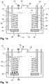
- FIG. 1a A synopsis of Figures 1a to 1b shows a humidifier 10 for a test chamber or a test room, not shown here, the humidifier 10 consisting of a container 11 with a container interior 12, in which a water bath 13 is accommodated, and a temperature control device 14, with a heating device 15 and a cooling device 16 for temperature control of the water bath 13 is formed.
- the humidifier 10 also includes an aeration device 17 for generating air bubbles 18 in the water bath 13.
- the heating device 15 comprises a heating coil 19 of a resistance heating element 20 , the heating coil 19 being positioned in the water bath 13 .
- the cooling device 16 has a cooling coil 21 which is formed from a tube 22 with a refrigerant circulating therein.
- the cooling coil 21 is also arranged inside the water bath 13 .
- the ventilation device 17 comprises two ventilation devices 23 and 24, which are spatially assigned to the heating device 15 and the cooling device 16, respectively.
- Each of the aerators 23 and 24 is made of a porous membrane 25 which is disc-shaped is formed, and a compressed air line 26 is formed.
- the compressed air lines 26 are each connected to a pump, not shown here, of the ventilation device 17 and can be supplied with compressed air separately from one another.
- the respective porous membranes 25 are arranged directly below the heating coil 19 or the cooling coil 21 relative to a water level 27 of the water bath 13 .
- a container opening 28 is formed above the water level 27, which merges into an air duct 29, which connects the container 11 to the test room, not shown here. Valves or similar devices are not provided in the air duct 29, so that the air duct 29 connects the container interior 12 to the test space in a substantially pressure-free manner.
- the humidifier 10 also includes a fill level sensor, not shown here, as well as an inlet valve 30 and an outlet valve 31. Water, in particular demineralized water, can be metered into the interior of the container 12 via the inlet valve 30, with water from the water bath 13 being drained from the interior of the container 12 using the outlet valve 31 can be. A height of the water level 27 can be kept essentially constant by dosing in the event of water loss as a result of evaporation. It is also possible to drain the water bath 13 completely, for example for maintenance purposes.
- the temperature control device 14 and the ventilation device 17 By controlling the temperature control device 14 and the ventilation device 17 with a control device of the humidifier 10 (not shown here), it is possible to set the temperature of the water bath 13 such that a dew point temperature of the saturated air can be set very precisely.
- An output of the humidifier 10 can optionally be very precisely regulated by regulating a delivery quantity of air via the pump of the ventilation device 17 in combination with the set dew point temperature.
- the heating device 15 with the ventilation device 23 can be switched off and the cooling device 16 with the ventilation device 24 can be switched on, so that the temperature of the water bath 13 and thus the dew point temperature of the air decrease.
- the humidifier 10 in the manner of an unpressurized steam humidifier.
- the water bath 13 can thus be heated by means of the heating coil 19 up to a boiling point of the water, in which case the steam thus generated can then be conducted via the air duct 29 to the test chamber.
- This output can be further increased if the pump of the aeration device 17 is activated during the boiling and air is blown into the water bath 13 via the aeration devices 23 or 24 .
- Such an increased degree of turbulence of the water bath 13 leads to a better expulsion of the steam generated from the container interior 12.
- the humidifier 10, with the control device not shown here, includes a test chamber control circuit, also not shown, and a humidifier control circuit with sensors for measuring temperature and/or relative humidity.
- the test chamber control circuit is coupled to the humidifier control circuit as part of a cascade control the test chamber control circuit is designed as a master controller and the humidifier control circuit is designed as a slave controller.
- an initial overheating of the water bath 13 can then also take place if a large quantity of saturated, warm air is to be introduced quickly into the test chamber.
- the test room can also be dehumidified via the control device by introducing very cold, saturated air into the test room. This air, which is then warmed up in the test space, can be enriched with water and discharged into an environment via a pressure relief valve in the test space, optionally also together with the pollutants of a test specimen located in the test space.
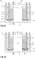
- a synopsis of Figures 2a to 2d 12 shows a further embodiment of a humidifier 32, the humidifier 32 being different from the humidifier 1 has a flow device 33 which is arranged on the heating coil 19 and the cooling coil 21 respectively.
- the flow device 33 forms a channel 34 with an upper end 35 and a lower end 36, each of which is open.
- the heating coil 19 and the cooling coil 21 are each arranged in the channel 34 .
- the channel 34 is formed here by a tube 37 which is widened at the lower end 36 .
- the upper end 35 projects beyond the water level 27 a little, for example a few centimeters.
- the water bath 13 is aerated with air bubbles 18 via the aerating device 24.
- the air bubbles 18 enter the channel 34 via the tube 37, which is widened at the lower end 26, so that the cooling coil 21 is intimately surrounded by air bubbles 18 flowing upward through the channel 34 . Consequently, the air bubbles 18 flow through a partial water quantity 38 of a total water quantity 39 of the water bath 13 in a targeted manner. This also leads to the raising of the water level 27 in the tube 37 compared to a Residual amount of water 40 of the water bath 13, which is not flowed through by air bubbles 18.
- the temperature of the partial amount of water 38 is controlled in the desired manner by means of the cooling coil 21, so that no temperature control of the total amount of water 39 is necessary here in order to generate saturated air with the desired dew point temperature. Since the partial amount of water 38 is many times smaller than the remaining amount of water 40 or the total amount of water 39, the partial amount of water 38 can also be tempered much faster than the total amount of water 39, so that with the help of the flow device 33 the humidifier 32 can be used in an energy-saving manner and with a possible dynamic temperature change during the balance the amount of air produced compared to the humidifier 1 can be operated.
- an amount of air in the aeration device 24 can also be increased to such an extent that the air bubbles 18 convey the water in the partial amount of water 38 beyond the upper end 35 of the pipe 37 and thus form a flow in the pipe 37 which mixes the partial amount of water 38 effected with the residual water quantity 40. If, for example, a temperature of the partial amount of water 38 is comparatively low and a temperature of the residual amount of water 40 is comparatively high, the two temperatures can be quickly equalized and thus a rapid temperature change in the partial amount of water 38 can be brought about. This makes it possible to generate air with dew point temperatures that differ significantly from one another within a few seconds using the humidifier 32 within the scope of a test interval.
- the Fig. 2d shows the humidifier 32 during operation of the ventilation devices 23 and 24, so that the residual water quantity 40 is completely mixed with the respective partial water quantities 38 here.
Description
Die Erfindung betrifft einen Befeuchter für eine Prüfkammer, eine Prüfkammer sowie ein Verfahren zur Konditionierung von Luft eines Prüfraums einer Prüfkammer, insbesondere Klimakammer oder dergleichen, wobei der Befeuchter einen Behälter mit einem Behälterinnenraum zur Aufnahme eines Wasserbades, eine Heizeinrichtung einer Temperiervorrichtung zur Temperierung des Wasserbades, und eine Belüftungsvorrichtung zur Erzeugung von Luftblasen im Wasserbad, aufweist, wobei oberhalb des Wasserbades in dem Behälter eine Behälteröffnung zur Verbindung des Behälterinnenraums mit einem Prüfraum einer Prüfkammer ausgebildet ist.The invention relates to a humidifier for a test chamber, a test chamber and a method for conditioning the air in a test space of a test chamber, in particular a climatic chamber or the like, the humidifier comprising a container with an interior space for accommodating a water bath, a heating device of a temperature control device for temperature control of the water bath, and an aeration device for generating air bubbles in the water bath, a container opening for connecting the interior of the container to a test space of a test chamber being formed above the water bath in the container.
Prüfkammern werden regelmäßig zur Überprüfung von physikalischen und/oder chemischen Eigenschaften von Gegenständen, insbesondere Vorrichtungen, eingesetzt. So sind Temperaturprüfschränke oder Klimaprüfschränke bekannt, innerhalb derer Temperaturen in einem Bereich von -50 °C bis +180 °C eingestellt werden können. Bei Klimaprüfschränken können ergänzend gewünschte Klimabedingungen eingestellt werden, denen dann die Vorrichtung beziehungsweise das Prüfgut über einen definierten Zeitraum ausgesetzt wird. Derartige Prüfkammern sind regelmäßig beziehungsweise teilweise als ein mobiles Gerät ausgebildet, welches lediglich mit erforderlichen Versorgungsleitungen mit einem Gebäude verbunden ist und alle zur Temperierung und Klimatisierung erforderlichen Baugruppen umfasst. Eine Temperierung eines das zu prüfende Prüfgut aufnehmenden Prüfraums erfolgt regelmäßig in einem Umluftkanal innerhalb des Prüfraums. In dem Umluftkanal sind ein oder mehrere Wärmetauscher zur Erwärmung oder Kühlung der den Umluftkanal beziehungsweise den Prüfraum durchströmenden Luft angeordnet. Dabei saugt ein Lüfter beziehungsweise ein Ventilator die im Prüfraum befindliche Luft an und leitet sie im Umluftkanal zu den jeweiligen Wärmetauschern. Das Prüfgut kann so temperiert oder auch einem definierten Temperaturwechsel ausgesetzt werden. Während eines Prüfintervalls kann dann beispielsweise eine Temperatur zwischen einem Temperaturmaximum und einem Temperaturminimum der Prüfkammer wechseln.Test chambers are regularly used to check the physical and/or chemical properties of objects, especially devices. Thus, temperature test cabinets or climate test cabinets are known within which temperatures can be set in a range from -50°C to +180°C. In the case of climatic test chambers, additional desired climatic conditions can be set, which then the device or the test material via a defined period of time is suspended. Such test chambers are regularly or partially designed as a mobile device, which is only connected to a building with the necessary supply lines and includes all the assemblies required for temperature control and air conditioning. Temperature control of a test room accommodating the test material to be tested is regularly carried out in a circulating air duct within the test room. One or more heat exchangers for heating or cooling the air flowing through the circulating air duct or the test chamber are arranged in the circulating air duct. A fan sucks in the air in the test room and directs it to the respective heat exchangers in the circulating air duct. The test material can be tempered in this way or exposed to a defined temperature change. During a test interval, for example, a temperature can then change between a maximum temperature and a minimum temperature of the test chamber.
Weiter ist regelmäßig vorgesehen, eine relative Luftfeuchte innerhalb des Prüfraums während eines Prüfintervalls einzustellen beziehungsweise die im Prüfraum befindliche Luft hinsichtlich ihrer relativen Feuchte zu konditionieren. Neben einer Entfeuchtung des Prüfraums über beispielsweise einen Kondensator wird daher ein im Klimaprüfschrank verbauter Befeuchter eingesetzt. Hier sind insbesondere Befeuchter bekannt, die innerhalb des Prüfraums in Art einer wannenartigen Vertiefung in einem Boden des Prüfraums ausgebildet sind. Die wannenartige Vertiefung weist dann ein Heizelement auf, mit dem in die Vertiefung eingefülltes Wasser erwärmt oder verdampft werden kann. Darüber hinaus kann auch ein Ablauf in der wannenartigen Vertiefung vorgesehen sein, über den das Wasser bei Bedarf abgelassen werden kann. Nachteilig ist hier, dass das innerhalb des Prüfraums befindliche Wasser Schadstoffe aus Prüflingen aufnehmen kann, was wiederum zu einer Korrosion von Bauteilen des Befeuchters, wie beispielsweise einem Heizelement, führen kann. Darüber hinaus kann das Wasser nicht während eines Prüfzyklus, sondern erst danach aus dem Prüfraum abgelassen werden, um den Prüfzyklus nicht zu beeinflussen. Eine Beeinflussung eines Prüfzyklus ist jedoch auch bei ausgeschalteter Befeuchterfunktion aufgrund des Wassers zumindest im geringen Maße nicht zu vermeiden. Gerade auch Prüfzyklen mit Temperaturwechseln bis unter einen Gefrierpunkt erfordern ein Ablassen des in der Wanne befindlichen Wassers. Diese Art von Befeuchtern ist vergleichsweise kostenaufwendig herzustellen, da für verschiedene Prüfkammergrößen stets entsprechend angepasste Befeuchter im Boden des betreffenden Prüfraums auszubilden sind.Provision is also regularly made to set a relative humidity within the test room during a test interval or to condition the air in the test room with regard to its relative humidity. In addition to dehumidifying the test room using a condenser, for example, a humidifier built into the climate test cabinet is used. In particular, humidifiers are known here that are designed inside the test space in the manner of a trough-like depression in a floor of the test space. The trough-like depression then has a heating element with which the water filled into the depression can be heated or evaporated. In addition, a drain can also be provided in the trough-like depression, via which the water can be drained if necessary. The disadvantage here is that the water located within the test chamber can absorb pollutants from test specimens, which in turn can lead to corrosion of components of the humidifier, such as a heating element. In addition, the water can not during a test cycle, but only then be let out of the test room so as not to influence the test cycle. However, an influencing of a test cycle due to the water, at least to a small extent, cannot be avoided even when the humidifier function is switched off. Especially test cycles with temperature changes to below freezing point require the water in the tub to be drained. This type of humidifier is comparatively expensive to produce, since humidifiers that are appropriately adapted to different test chamber sizes always have to be constructed in the floor of the relevant test room.
Die
Nachteilig bei dem bekannten Befeuchter ist, dass eine Befeuchtung aufgrund der im Behälter befindlichen Wassermenge nur sehr träge regelbar ist. Eine hohe Feuchtekonstanz oder auch ein schneller Wechsel einer Lufttemperatur beziehungsweise einer relativen Luftfeuchte in dem Prüfraum im Rahmen eines Prüfintervalls kann daher mit dem Befeuchter nicht realisiert werden. Gerade auch ein Absenken einer Lufttemperatur im Prüfraum erfordert eine Entfeuchtung der Luft im Prüfraum mit beispielsweise einem Entfeuchter.The disadvantage of the known humidifier is that humidification can only be regulated very sluggishly due to the amount of water in the container. A high level of humidity constancy or a rapid change in air temperature or relative humidity in the test room within the scope of a test interval can therefore not be achieved with the humidifier. A drop in the air temperature in the test room also requires the air in the test room to be dehumidified, for example with a dehumidifier.
Die
Aus der
Auch die
Der vorliegenden Erfindung liegt daher die Aufgabe zugrunde, einen Befeuchter für eine Prüfkammer und ein Verfahren zur Konditionierung von Luft eines Prüfraums einer Prüfkammer vorzuschlagen, welcher beziehungsweise welches auch bei sich schnell ändernden Prüfbedingungen eine hohe Konstanz einer relativen Luftfeuchte in einem Prüfraum ermöglicht.The present invention is therefore based on the object of proposing a humidifier for a test chamber and a method for conditioning the air in a test chamber of a test chamber, which enables a high degree of constancy of relative humidity in a test chamber even under rapidly changing test conditions.
Diese Aufgabe wird durch einen Befeuchter mit den Merkmalen des Anspruchs 1, eine Prüfkammer mit den Merkmalen des Anspruchs 10 und ein Verfahren mit den Merkmalen des Anspruchs 12 gelöst.This object is achieved by a humidifier having the features of claim 1, a test chamber having the features of
Der erfindungsgemäße Befeuchter für eine Prüfkammer, insbesondere Klimakammer, weist einen Behälter mit einem Behälterinnenraum zur Aufnahme eines Wasserbades, eine Heizeinrichtung einer Temperiervorrichtung zur Temperierung des Wasserbades, und eine Belüftungsvorrichtung zur Erzeugung von Luftblasen im Wasserbad, auf, wobei oberhalb des Wasserbades in dem Behälter eine Behälteröffnung zur Verbindung des Behälterinnenraums mit einem Prüfraum einer Prüfkammer ausgebildet ist, wobei der Befeuchter eine Kühleinrichtung der Temperiervorrichtung aufweist, wobei die Heizeinrichtung und die Kühleinrichtung jeweils mit einem in dem Wasserbad angeordneten Wärmetauscher ausgebildet sind.The humidifier according to the invention for a test chamber, in particular a climatic chamber, has a container with a container interior for accommodating a water bath, a heating device of a temperature control device for temperature control of the water bath, and an aeration device for generating air bubbles in the water bath, with a Container opening for connecting the container interior is formed with a test space of a test chamber, wherein the humidifier has a cooling device of the temperature control device, wherein the heating device and the Cooling device are each formed with a heat exchanger arranged in the water bath.
Der Behälter des Befeuchters ist im Wesentlichen geschlossen und temperaturisoliert und die Heizeinrichtung ist in dem Wasserbad angeordnet, sodass das Wasserbad mittels der Heizeinrichtung erwärmt werden kann. Die Behälteröffnung dient zur dichten Verbindung mit einem Prüfraum, sodass befeuchtete Luft aus dem Behälter über beispielsweise einen Luftkanal oder Schlauch in einen Prüfraum eingeleitet werden kann. Der Befeuchter ist so prinzipiell unabhängig von einer Größe einer Prüfkammer beziehungsweise eines Prüfraums modular ausbildbar. Auch ist es dann nicht mehr erforderlich, innerhalb eines Prüfraums individuell angepasste Befeuchter auszubilden, weshalb der erfindungsgemäße Befeuchter besonders kostengünstig herstellbar ist. Dadurch, dass der Befeuchter die in dem Wasserbad angeordnete Kühleinrichtung der Temperiervorrichtung aufweist, wird es möglich, das Wasserbad so zu temperieren, dass es eine vergleichsweise niedrige Temperatur aufweist. Hierdurch können schnelle Temperaturwechsel des Befeuchters beziehungsweise des Wasserbades und damit befeuchtete, aerosolfreie Luft mit einer beliebigen Taupunkttemperatur erzeugt werden. Darüber hinaus kann auch eine Entfeuchtung des Prüfraums mittels des Befeuchters durchgeführt werden.The tank of the humidifier is essentially closed and temperature-insulated and the heater is arranged in the water bath so that the water bath can be heated by the heater. The container opening is used for a tight connection to a test room, so that humidified air from the container can be introduced into a test room via an air duct or hose, for example. In principle, the humidifier can be designed in a modular manner independently of the size of a test chamber or a test room. It is also then no longer necessary to design individually adapted humidifiers within a test room, which is why the humidifier according to the invention can be produced particularly cost-effectively. The fact that the humidifier has the cooling device of the temperature control device arranged in the water bath makes it possible to control the temperature of the water bath in such a way that it has a comparatively low temperature. As a result, rapid temperature changes in the humidifier or the water bath and thus humidified, aerosol-free air with any desired dew point temperature can be generated. In addition, the test room can also be dehumidified using the humidifier.
Durch die nunmehr mögliche Kühlung des Wasserbades kann eine genaue zeitliche Konstanz einer relativen Luftfeuchte in dem Prüfraum erzielt werden, da die Temperatur des Wasserbades auch schnell abgesenkt und damit vergleichsweise genau geregelt werden kann. Weiter kann eine sehr niedrige Temperatur des Wasserbades mittels der Kühleinrichtung eingestellt werden, sodass dann vergleichsweise kalte, aerosolfreie Luft in den Prüfraum gefördert werden kann. Eine Erwärmung dieser Luft in dem Prüfraum führt zu einer Verminderung einer relativen Luftfeuchte innerhalb des Prüfraums und damit auch zu einer Entfeuchtung desselben. Hier kann insbesondere vorgesehen sein, Luft über ein Auslassventil im Prüfraum aus diesem auszuleiten, sodass eine besonders schnelle Entfeuchtung mit einem Austrag von gegebenenfalls in der Luft befindlichen Schadstoffen erfolgen kann. Neben der hohen zeitlichen Konstanz einer relativen Luftfeuchte im Prüfraum ist folglich auch ein schneller Wechsel einer Taupunkttemperatur im Prüfraum möglich. Der erfindungsgemäße Befeuchter ist aufgrund seines modularen Aufbaus für verschiedenste Prüfkammern verwendbar.Due to the cooling of the water bath that is now possible, a precise temporal constancy of a relative humidity in the test room can be achieved, since the temperature of the water bath can also be lowered quickly and can therefore be regulated comparatively precisely. Furthermore, a very low temperature of the water bath can be set by means of the cooling device, so that comparatively cold, aerosol-free air can then be conveyed into the test room. Heating this air in the test room leads to a reduction in relative humidity within the test room and thus also to dehumidification of the same. In particular, air can be provided here via an outlet valve in the test room from this, so that a particularly fast dehumidification can take place with a discharge of any pollutants in the air. In addition to the high temporal constancy of relative humidity in the test room, a rapid change in dew point temperature in the test room is also possible. Due to its modular design, the humidifier according to the invention can be used for a wide variety of test chambers.
Erfindungsgemäß sind die Heizeinrichtung und die Kühleinrichtung jeweils mit einem in dem Wasserbad angeordneten Wärmetauscher ausgebildet. Der Wärmetauscher der Heizeinrichtung kann beispielsweise ein elektrischer Heizstab oder auch ein mit einem Wärmeträgermedium durchströmtes Rohr sein. Die Kühleinrichtung kann ebenfalls ein mit einem Wärmeträgermedium beziehungsweise mit einem Kältemittel durchströmtes Rohr innerhalb dem Wasserbad sein. Das Rohr kann beispielsweise in Art einer Schlange, spiralförmig oder wendelförmig ausgebildet sein, sodass ein möglichst guter Wärmeübergang von der Heizeinrichtung beziehungsweise der Kühleinrichtung zu dem Wasserbad erzielbar ist.According to the invention, the heating device and the cooling device are each designed with a heat exchanger arranged in the water bath. The heat exchanger of the heating device can be, for example, an electric heating rod or a tube through which a heat transfer medium flows. The cooling device can also be a pipe inside the water bath through which a heat transfer medium or a refrigerant flows. The tube can be designed, for example, in the form of a snake, spiral or helical, so that the best possible heat transfer from the heating device or the cooling device to the water bath can be achieved.
Der Heizeinrichtung und der Kühleinrichtung können jeweils eine Belüftungseinrichtung der Belüftungsvorrichtung räumlich zugeordnet sein. Diese Belüftungseinrichtungen können dann jeweils in dem Wasserbad angeordnet sein. Die jeweiligen Belüftungseinrichtungen können unterhalb der Heizeinrichtung beziehungsweise der Kühleinrichtung angeordnet sein, sodass mit den Belüftungseinrichtungen erzeugte Luftblasen im Bereich der Heizeinrichtung beziehungsweise der Kühleinrichtung in dem Wasserbad aufsteigen können. So wird es möglich, eine möglichst direkte Beeinflussung der Luft in dem Behälterinnenraum über die Heizeinrichtung beziehungsweise die Kühleinrichtung zu erzielen. Auch können die Belüftungseinrichtungen voneinander separiert sein, sodass ein getrennter Betrieb der Belüftungseinrichtungen beziehungsweise eine voneinander unabhängige Erzeugung von Luftblasen in dem Wasserbad erfolgen kann. Die Belüftungsvorrichtung kann weiter zumindest eine Pumpe aufweisen, mittels der die Belüftungseinrichtungen mit Luft versorgt werden können. Dabei kann auch eine Luftmenge auf die Belüftungseinrichtungen unterschiedlich verteilt werden. So kann beispielsweise zunächst die Heizeinrichtung zur Erzeugung von warmer, gesättigter Luft betrieben und mit Luftblasen über die räumlich zugeordnete Belüftungseinrichtung versorgt werden. Ist im Rahmen eines Prüfintervalls eine Abkühlung eines Prüflings beziehungsweise von Luft im Prüfraum vorgesehen, kann nachfolgend eine Abkühlung des Wasserbades durch einen Betrieb der Kühleinrichtung erfolgen, wobei dann die Kühleinrichtung von Luftblasen der zugeordneten Belüftungseinrichtung umströmt wird, sodass vergleichsweise kalte, gesättigte Luft für den Prüfraum erzeugt werden kann.A ventilation device of the ventilation device can each be spatially assigned to the heating device and the cooling device. These ventilation devices can then each be arranged in the water bath. The respective aeration devices can be arranged below the heating device or the cooling device, so that air bubbles generated by the aeration devices can rise in the area of the heating device or the cooling device in the water bath. It is thus possible to influence the air in the interior of the container as directly as possible via the heating device or the cooling device. The aeration devices can also be separated from one another, so that the aeration devices can be operated separately or air bubbles can be generated independently of one another in the water bath can be done. The ventilation device can also have at least one pump, by means of which the ventilation devices can be supplied with air. A quantity of air can also be distributed differently over the ventilation devices. For example, the heating device can initially be operated to generate warm, saturated air and supplied with air bubbles via the spatially assigned ventilation device. If a test object or air in the test room is to be cooled during a test interval, the water bath can then be cooled by operating the cooling device, with air bubbles from the associated ventilation device then flowing around the cooling device, so that comparatively cold, saturated air is available for the test room can be generated.
Die jeweiligen Belüftungseinrichtungen können eine Druckluftleitung mit einem Luftauslass aufweisen, wobei jeweils eine poröse Membran den Luftauslass ausbilden kann, wobei die poröse Membran jeweils unterhalb der Heizeinrichtung und der Kühleinrichtung angeordnet sein kann. Die poröse Membran kann beispielsweise aus einem porösen keramischen Material in Art eines sogenannten Perlators ausgebildet sein. Die Druckluftleitung kann ein Rohr oder ein Schlauch sein, der eine Pumpe zur Förderung von Luft beziehungsweise zur Erzeugung von Druckluft mit einer Belüftungseinrichtung verbindet. Durch die Verwendung der porösen Membran wird es möglich, eine große Anzahl von Luftblasen gleichzeitig zu erzeugen und damit auch eine besonders große Oberfläche des Wasserbades im Bereich der Heizeinrichtung und/oder der Kühleinrichtung auszubilden. Mit Wasser gesättigte Luft beziehungsweise Luft mit einer bestimmten Taupunkttemperatur kann so vergleichsweise schnell in großer Menge erzeugt und zu einem Prüfraum geleitet werden.The respective ventilation devices can have a compressed air line with an air outlet, in which case a porous membrane can form the air outlet, in which case the porous membrane can be arranged below the heating device and the cooling device. The porous membrane can be formed, for example, from a porous ceramic material in the manner of a so-called aerator. The compressed air line can be a pipe or a hose that connects a pump for conveying air or for generating compressed air with an aeration device. The use of the porous membrane makes it possible to generate a large number of air bubbles at the same time and thus also to form a particularly large surface of the water bath in the area of the heating device and/or the cooling device. Air saturated with water or air with a specific dew point temperature can thus be generated comparatively quickly in large quantities and fed to a test room.
Vorteilhaft kann die poröse Membran scheibenförmig ausgebildet sein. Die poröse Membran kann unterhalb der Heizeinrichtung und der Kühleinrichtung relativ zu einem Wasserspiegel des Wasserbades so angeordnet sein, dass die Heizeinrichtung beziehungsweise die Kühleinrichtung zumindest vollständig von den Luftblasen umgeben werden kann. Mit der scheibenförmigen, porösen Membran können dann auf einer großen Fläche bei gleichzeitig einer geringen Bauhöhe der porösen Membran Luftblasen erzeugt werden.Advantageously, the porous membrane can be disc-shaped. The porous membrane can be below the heating device and the cooling device be arranged relative to a water level of the water bath so that the heating device or the cooling device can be at least completely surrounded by the air bubbles. With the disk-shaped, porous membrane, air bubbles can then be generated over a large area while at the same time having a low overall height of the porous membrane.
Der Befeuchter kann eine Strömungsvorrichtung aufweisen, wobei die Strömungsvorrichtung einen im Behälter angeordneten Kanal aufweisen kann, dessen oberes Ende und dessen unteres Ende offen ausgebildet sein können, wobei der Wärmetauscher dann in dem Kanal angeordnet sein kann. Folglich kann die Strömungsvorrichtung in Art eines vertikal angeordneten Schachtes in dem Wasserbad positioniert sein, sodass der Wärmetauscher der Heizeinrichtung und/oder der Kühleinrichtung innerhalb der Strömungsvorrichtung beziehungsweise des Kanals angeordnet sein kann. Insbesondere wenn eine Erzeugung von Luftblasen mittels der Belüftungsvorrichtung unterhalb des jeweiligen Wärmetauschers erfolgt, können die Luftblasen dann den Kanal durchströmen und damit mit den jeweiligen Wärmetauscher umgeben. Auch kann mittels der Strömungsvorrichtung dann sichergestellt werden, dass im Wesentlichen das innerhalb der Strömungsvorrichtung beziehungsweise dem Kanal befindliche Wasser des Wasserbades von dem jeweiligen Wärmetauscher erhitzt oder gekühlt wird. Die dann durch den Kanal hindurch strömenden Luftblasen werden so gezielt durch das erhitzte oder gekühlte Wasser hindurch geleitet, was eine besonders schnelle Erzeugung gesättigter Luft mit der gewünschten Taupunkttemperatur ermöglicht. Insbesondere ist es dann auch nicht mehr erforderlich, das gesamte Wasserbad vollständig auf die gewünschte Temperatur zur Erzeugung der gesättigten Luft zu erbringen, sondern es ist bereits ausreichend, nur das innerhalb des Kanals befindliche Wasser zu temperieren. Das außerhalb des Kanals befindliche Wasser dient dann lediglich als eine Verdampfungsreserve und kann nach Bedarf in den Kanal einströmen. Der Kanal kann so groß ausgebildet sein, dass ein Innenvolumen des Kanals im Verhältnis zu einem Gesamtvolumen des Wasserbades 1:5, 1:10 oder größer ist. Dadurch, dass die Luftblasen in dem Kanal aufsteigen können, kann auch ein Einfrieren des Wärmetauschers der Kühleinrichtung einfach verhindert werden. Wenn ein besonders gut kühlbarer Wärmetauscher verwendet wird, kann Wasser an der Oberfläche des Wärmetauschers gefrieren, was dazu führt, dass der Befeuchter außer Betrieb genommen und abgetaut werden muss. Wenn die aufsteigenden Luftblasen eine turbulente Strömung im Bereich einer Oberfläche des Wärmetauschers erzeugen, kann eine Eisbildung an der Oberfläche einfach verhindert werden.The humidifier can have a flow device, wherein the flow device can have a channel arranged in the container, the upper end and the lower end of which can be open, in which case the heat exchanger can then be arranged in the channel. Consequently, the flow device can be positioned in the manner of a vertically arranged shaft in the water bath, so that the heat exchanger of the heating device and/or the cooling device can be arranged within the flow device or the channel. In particular, if air bubbles are generated by means of the ventilation device below the respective heat exchanger, the air bubbles can then flow through the duct and thus surround the respective heat exchanger. The flow device can also be used to ensure that essentially the water of the water bath located within the flow device or the channel is heated or cooled by the respective heat exchanger. The air bubbles that then flow through the duct are then guided through the heated or cooled water in a targeted manner, which enables saturated air with the desired dew point temperature to be generated particularly quickly. In particular, it is then no longer necessary to bring the entire water bath to the desired temperature for generating the saturated air, but it is already sufficient to temper only the water located within the channel. The water located outside the channel then only serves as an evaporation reserve and can flow into the channel as required. The channel can be made so large that an internal volume of the channel in the Ratio to a total volume of the water bath is 1:5, 1:10 or greater. The fact that the air bubbles can rise in the duct also makes it easy to prevent the heat exchanger of the cooling device from freezing. If a particularly well-cooled heat exchanger is used, water can freeze on the surface of the heat exchanger, resulting in the humidifier having to be shut down and defrosted. If the rising air bubbles create a turbulent flow in the area of a surface of the heat exchanger, ice formation on the surface can be easily prevented.
So kann der Kanal von einem Hohlprofil in Art eines Rohrs ausgebildet sein, wobei eine Oberkante des oberen Endes oberhalb eines Wasserspiegels des Wasserbades angeordnet sein kann. Folglich kann der Wasserspiegel auch so weit angehoben sein, dass die Oberkante stets oberhalb des Wasserspiegels liegt beziehungsweise aus dem Wasserbad herausragt. Je nach der mit der Belüftungsvorrichtung eingeblasenen Luftmenge bewirken die Luftblasen innerhalb des Hohlprofils ein Anheben des Wasserspiegels in dem Hohlprofil relativ zu dem Wasserspiegel in dem übrigen Behälterinnenraum beziehungsweise einer Restwassermenge des Wasserbades. Die Luftblasen bewirken ein "Aufschäumen" des Wasserspiegels einer im Kanal befindlichen Teilwassermenge des Wasserbades. Insbesondere kann dann der Wasserspiegel auch so hoch angehoben werden, dass Wasser des Wasserbades beziehungsweise der Teilwassermenge über die Oberkante aus dem Hohlprofil heraus tritt und sich mit der Restwassermenge des Wasserbades außerhalb des Hohlprofils mischt. Je nach Dosierung einer Luftmenge kann dann auch eine schnelle Durchmischung des Wasserbades mit durch die Wärmetauscher erzeugtem warmen und/oder kalten Wasser durchgeführt werden, um eine Durchschnittstemperatur des Wasserbades beziehungsweise einer Gesamtwassermenge anzuheben oder abzusenken.Thus, the channel can be formed from a hollow profile in the manner of a tube, with an upper edge of the upper end being able to be arranged above a water level of the water bath. Consequently, the water level can also be raised to such an extent that the upper edge is always above the water level or protrudes from the water bath. Depending on the amount of air blown in with the ventilation device, the air bubbles within the hollow profile raise the water level in the hollow profile relative to the water level in the rest of the container interior or a residual amount of water in the water bath. The air bubbles cause the water level in a part of the water bath in the channel to "foam up". In particular, the water level can then also be raised so high that the water in the water bath or the partial amount of water emerges from the hollow profile over the upper edge and mixes with the remaining amount of water in the water bath outside of the hollow profile. Depending on the dosage of an amount of air, the water bath can then also be quickly mixed with warm and/or cold water generated by the heat exchanger in order to raise or lower an average temperature of the water bath or a total amount of water.
Vorteilhaft ist es, wenn der Wärmetauscher der Heizeinrichtung und der Wärmetauscher der Kühleinrichtung jeweils innerhalb des Hohlprofils angeordnet ist. Folglich kann dann der Heizeinrichtung und der Kühleinrichtung jeweils ein Hohlprofil zugeordnet sein. Dann wird es beispielsweise auch möglich, den jeweiligen Wärmetauscher der Heizeinrichtung und der Kühleinrichtung gleichzeitig mit Luftblasen zu versorgen beziehungsweise zu umströmen. So kann während eines Ausklingens einer Beheizungsphase bereits eine Kühlphase eingeleitet, und so ein schneller Wechsel einer Befeuchterfunktion verwirklicht werden. Der Kanal kann derart ausgebildet und Belüftungseinrichtungen der Belüftungsvorrichtung jeweils unterhalb oder innerhalb des Kanals angeordnet sein, dass ein Aufsteigen von Luftblasen in dem Wasserbad überwiegend, bevorzugt ausschließlich innerhalb des Kanals, erfolgt.It is advantageous if the heat exchanger of the heating device and the heat exchanger of the cooling device are each arranged inside the hollow profile. Consequently, a hollow profile can then be assigned to the heating device and the cooling device. It is then also possible, for example, to simultaneously supply or flow around the respective heat exchanger of the heating device and the cooling device with air bubbles. A cooling phase can thus already be initiated while a heating phase is fading away, and a rapid change in a humidifier function can thus be implemented. The channel can be designed and ventilation devices of the ventilation device can be arranged below or inside the channel in such a way that air bubbles in the water bath rise predominantly, preferably exclusively inside the channel.
Weiter kann der Befeuchter einen Füllstandsensor, ein Zulaufventil und ein Ablaufventil aufweisen. Über das Zulaufventil kann Wasser in den Behälterinnenraum dosiert werden, wobei über das Ablaufventil Wasser nach Bedarf aus dem Behälterinnenraum abgelassen werden kann. Der Füllstandsensor kann zusammen mit einer Regeleinrichtung zur konstanten Regelung einer Höhe eines Wasserspiegels in dem Behälterinnenraum genutzt werden. Insbesondere wenn Wasser mit gesättigter Luft aus dem Behälterinnenraum ausgetragen wird, kann ein Wasserverlust durch Nachdosieren mit dem Zulaufventil ausgeglichen werden. Um eine gegebenenfalls erforderliche Reinigung des Behälterinnenraums beziehungsweise des Befeuchters aufgrund von Rückständen in dem Wasser zu vermeiden, kann demineralisiertes Wasser für das Wasserbad verwendet werden.Furthermore, the humidifier can have a level sensor, an inlet valve and an outlet valve. Water can be metered into the interior of the container via the inlet valve, and water can be drained from the interior of the container via the outlet valve as required. The fill level sensor can be used together with a control device for constant control of the height of a water level in the interior of the container. In particular, if water is discharged from the interior of the container with saturated air, a loss of water can be compensated for by replenishing with the inlet valve. Demineralized water can be used for the water bath in order to avoid cleaning the interior of the container or the humidifier that may be necessary due to residues in the water.
Die erfindungsgemäße Prüfkammer zur Konditionierung von Luft umfasst einen gegenüber einer Umgebung verschließbaren und temperaturisolierten Prüfraum zur Aufnahme von Prüfgut sowie einen erfindungsgemäßen Befeuchter. Weitere vorteilhafte Ausführungsformen einer Prüfkammer ergeben sich aus den auf den Vorrichtungsanspruch 1 rückbezogenen Unteransprüchen.The test chamber according to the invention for conditioning air comprises a test space that can be closed off from the environment and is temperature-insulated for receiving test material, as well as a humidifier according to the invention. Further advantageous embodiments of a test chamber result from the subclaims referring back to the device claim 1.
Eine besonders hohe zeitliche Konstanz einer relativen Feuchte kann mit dem Befeuchter erzielt werden, wenn der Befeuchter eine Regeleinrichtung mit einem Prüfkammerregelkreis und einem Befeuchterregelkreis aufweist, wobei der Prüfkammerregelkreis einen Feuchtesensor zur Messung einer relativen Luftfeuchte in dem Prüfraum aufweisen und zur Feuchteregelung in dem Prüfraum dienen kann, wobei der Befeuchterregelkreis einen Temperatursensor zur Messung der Temperatur in dem Wasserbad und/oder einen Feuchtesensor, bevorzugt einen Taupunktsensor, zur Messung einer relativen Luftfeuchte in dem Behälterinnenraum aufweisen kann, und dann zur Feuchteregelung und/oder Temperaturregelung in dem Behälterinnenraum dienen kann, wobei die Regeleinrichtung als eine Kaskadenregelung mit dem Prüfkammerregelkreis als ein Führungsregler und dem Befeuchterregelkreis als ein Folgeregler ausgebildet sein kann. Die dann so ausgebildete Kaskadenregelung ermöglicht neben einer verbesserten, absoluten Genauigkeit des Befeuchters hinsichtlich der befeuchteten Luft in dem Prüfraum auch eine schnellere Reaktion beziehungsweise ein zeitlich schnelleres Ansprechverhalten des Befeuchters und damit eine dynamischere Steuerung von Prüfintervallen. So kann beispielsweise eine Absenkung einer relativen Luftfeuchte in einem Prüfraum durch Erzeugung einer zunächst stark unterkühlten, tiefen Wassertemperatur in den Befeuchter eingeleitet werden und umgekehrt. Eine Anpassung der betreffenden Wassertemperatur und geförderten Luftmenge kann mit dem Befeuchterregelkreis gleitend erfolgen. Bei dem erfindungsgemäßen Verfahren zur Konditionierung von Luft eines Prüfraums einer Prüfkammer, insbesondere Klimakammer, mit einem Befeuchter, wird in einem Behälterinnenraum eines Behälters des Befeuchters ein Wasserbad aufgenommen, wobei mittels einer Heizeinrichtung einer Temperiervorrichtung des Befeuchters eine Temperierung des Wasserbades erfolgt, wobei mittels einer Belüftungsvorrichtung des Befeuchters Luftblasen in dem Wasserbad erzeugt werden, wobei oberhalb des Wasserbades eine in dem Behälter ausgebildete Behälteröffnung den Behälterinnenraum mit einem Prüfraum einer Prüfkammer verbindet, wobei mittels einer Kühleinrichtung der Temperiervorrichtung des Befeuchters eine Temperierung des Wasserbades erfolgt, wobei die Heizeinrichtung und die Kühleinrichtung jeweils mit einem in dem Wasserbad angeordneten Wärmetauscher ausgebildet sind.A particularly high temporal constancy of relative humidity can be achieved with the humidifier if the humidifier has a control device with a test chamber control circuit and a humidifier control circuit, with the test chamber control circuit having a humidity sensor for measuring relative humidity in the test room and for humidity control in the test room , wherein the humidifier control circuit can have a temperature sensor for measuring the temperature in the water bath and/or a humidity sensor, preferably a dew point sensor, for measuring relative humidity in the interior of the container, and can then be used for humidity control and/or temperature regulation in the interior of the container, wherein the Control device can be designed as a cascade control with the test chamber control circuit as a master controller and the humidifier control circuit as a slave controller. The cascade control then designed in this way allows not only an improved, absolute accuracy of the humidifier with regard to the humidified air in the test room but also a faster reaction or a faster response behavior of the humidifier and thus a more dynamic control of test intervals. For example, a reduction in relative humidity in a test room can be introduced into the humidifier by generating an initially very subcooled, low water temperature, and vice versa. The relevant water temperature and conveyed air volume can be adjusted smoothly with the humidifier control circuit. In the method according to the invention for conditioning the air of a test space of a test chamber, in particular a climatic chamber, with a humidifier, a water bath is accommodated in a container interior of a container of the humidifier, with the water bath being temperature controlled by means of a heating device of a temperature control device of the humidifier, with a Ventilation device of the humidifier, air bubbles are generated in the water bath, with a container opening formed in the container above the water bath connecting the interior of the container with a test space of a test chamber, with the water bath being temperature controlled by means of a cooling device of the temperature control device of the humidifier, the heating device and the cooling device each are formed with a heat exchanger arranged in the water bath.
Zu den vorteilhaften Wirkungen des erfindungsgemäßen Verfahrens wird auf die Vorteilsbeschreibung des erfindungsgemäßen Befeuchters verwiesen. Demnach erfolgt eine ergänzende Temperierung des Wasserbades mittels der Kühleinrichtung, was eine schnelle Abkühlung des Wasserbades und damit eine Erzeugung gesättigter Luft mit einer vergleichsweise niedrigeren Taupunkttemperatur ermöglicht.With regard to the advantageous effects of the method according to the invention, reference is made to the description of the advantages of the humidifier according to the invention. Accordingly, an additional temperature control of the water bath takes place by means of the cooling device, which enables rapid cooling of the water bath and thus generation of saturated air with a comparatively lower dew point temperature.
Das Wasserbad kann mittels der Heizeinrichtung und der Kühleinrichtung in einem Temperaturbereich von 2 °C bis 100 °C, bevorzugt von 10 °C bis 100 °C temperiert werden. Gerade eine niedrige Wassertemperatur kann dazu genutzt werden, den Prüfraum beziehungsweise dessen Luftfeuchte innerhalb eines Prüfintervalls auch bei niedrigen Lufttemperaturen anzupassen beziehungsweise gezielt zu regeln. Weiter kann kalte Luft auch zur Entfeuchtung des Prüfraums genutzt werden. Umgekehrt ist es möglich das Wasserbad soweit zu erhitzen, dass das Wasser kocht und der Befeuchter dann in Art eines Dampferzeugers genutzt werden kann. Dadurch, dass über die Belüftungsvorrichtung des Befeuchters Luftblasen in dem Wasserbad erzeugt werden, wird über beispielsweise eine Pumpe der Belüftungsvorrichtung dem Behälterinnenraum stetig Luft zugeführt. Diese Luft kann dann über beispielsweise einen Luftkanal oder einen Schlauch in den Prüfraum eingeleitet werden, wobei ein Transport der Luft über eine Partialdruckdifferenz zwischen Behälterinnenraum und Prüfraum erfolgen kann. Optional ist es natürlich auch möglich, mit beispielsweise einem Ventilator gezielt eine Luftströmung von dem Behälterinnenraum in dem Prüfraum auszubilden.The water bath can be tempered in a temperature range from 2° C. to 100° C., preferably from 10° C. to 100° C., by means of the heating device and the cooling device. A low water temperature in particular can be used to adapt or specifically regulate the test room or its humidity within a test interval, even at low air temperatures. Cold air can also be used to dehumidify the test room. Conversely, it is possible to heat the water bath to such an extent that the water boils and the humidifier can then be used like a steam generator. Due to the fact that air bubbles are generated in the water bath via the ventilation device of the humidifier, air is continuously supplied to the interior of the container via, for example, a pump of the ventilation device. This air can then be introduced into the test chamber via an air duct or a hose, for example, and the air can be transported via a partial pressure difference between the interior of the container and the test chamber. Of course it is also optional possible to use a fan, for example, to specifically form an air flow from the container interior into the test room.
Ein Wärmetauscher der Heizeinrichtung und ein Wärmetauscher der Kühleinrichtung können jeweils in einem Kanal einer Strömungsvorrichtung des Befeuchters in dem Wasserbad angeordnet sein, wobei innerhalb des jeweiligen Kanals eine Teilwassermenge einer Gesamtwassermenge des Wasserbades mittels des jeweiligen Wärmetauschers temperiert werden kann. Die Teilwassermenge kann ein Fünftel, ein Zehntel oder weniger der Gesamtwassermenge beziehungsweise einer Restwassermenge des Wasserbades betragen. So ist es bereits ausreichend, einen Bruchteil der Gesamtwassermenge zu temperieren, um gesättigte, aerosolfreie Luft mittels der Luftblasen in dem Wasserbad zu erzeugen. Durch die Temperierung der jeweiligen Teilwassermenge kann eine Ansprechgeschwindigkeit beziehungsweise eine Dynamik des Befeuchters bei einer Konditionierung von Luft wesentlich verbessert werden.A heat exchanger for the heating device and a heat exchanger for the cooling device can each be arranged in a channel of a flow device of the humidifier in the water bath, with a partial amount of water of a total amount of water in the water bath being able to be temperature-controlled within the respective channel by means of the respective heat exchanger. The partial amount of water can be a fifth, a tenth or less of the total amount of water or a residual amount of water in the water bath. It is already sufficient to temper a fraction of the total amount of water in order to generate saturated, aerosol-free air using the air bubbles in the water bath. By controlling the temperature of the respective partial amount of water, a response speed or dynamics of the humidifier can be significantly improved when air is conditioned.
Folglich kann die Teilwassermenge mit einer von einer Restwassermenge der Gesamtwassermenge wesentlich abweichenden Temperatur temperiert werden. Wenn dies erforderlich sein sollte, kann auch durch eine mittels der Belüftungsvorrichtung initiierte Durchmischung der Teilwassermenge mit der Restwassermenge ein Temperaturausgleich von der Teilwassermenge mit der Restwassermenge schnell erzielt werden.Consequently, the partial amount of water can be tempered with a temperature that deviates significantly from a remaining amount of water in the total amount of water. If this should be necessary, a temperature equalization of the partial water quantity with the residual water quantity can also be quickly achieved by means of the aeration device initiated by mixing the partial quantity of water with the residual quantity of water.
Es kann vorgesehen sein, mittels der Belüftungsvorrichtung eine Menge von Luftblasen zu erzeugen, die innerhalb eines Hohlprofils des Kanals in dem Wasserbad aufsteigen, wobei dann eine Oberkante des Hohlprofils oberhalb eines Wasserspiegels des Wasserbades angeordnet sein kann. Die Luftblasen steigen dann im Wesentlichen alleine in der Teilwassermenge, die temperiert wird, auf, sodass im Wesentlichen alleine die temperierte Teilwassermenge zur Erzeugung der gesättigten Luft verwendet werden kann.Provision can be made for the aeration device to generate a quantity of air bubbles which rise within a hollow profile of the channel in the water bath, in which case an upper edge of the hollow profile can then be arranged above a water level of the water bath. The air bubbles then rise essentially solely in the partial amount of water that is tempered, so that essentially only the tempered partial amount of water can be used to generate the saturated air.
Die Luftblasen können in der Teilwassermenge aufsteigen und den Wasserspiegel innerhalb des Hohlprofils relativ zu dem Wasserspiegel außerhalb des Hohlprofils erhöhen. Solange eine Erhöhung des Wasserspiegels innerhalb des Hohlprofils die Oberkante des Hohlprofils nicht übersteigt, kann eine Durchmischung der Teilwassermenge mit der Restwassermenge weitestgehend ausgeschlossen werden. Je nach eingestellter Temperatur der Wassermenge kann auch eine Taupunkttemperatur der über die Luftblasen entweichenden Luft beziehungsweise Luftmenge sehr genau eingestellt werden. So ist es möglich, eine sehr hohe zeitliche Konstanz der relativen Luftfeuchte im Prüfraum über die Zuleitung eines gesättigten Luftstroms in den Prüfraum sicherzustellen.The air bubbles can rise in the partial amount of water and increase the water level inside the hollow profile relative to the water level outside the hollow profile. As long as an increase in the water level within the hollow profile does not exceed the upper edge of the hollow profile, mixing of the partial water volume with the residual water volume can be largely ruled out. Depending on the set temperature of the amount of water, a dew point temperature of the air or amount of air escaping via the air bubbles can also be set very precisely. It is thus possible to ensure a very high level of constancy over time in the relative humidity in the test room by feeding a saturated air flow into the test room.
Die Luftblasen können auch in der Teilwassermenge aufsteigen und die Teilwassermenge über die Oberkante des Hohlprofils aus dem Hohlprofil hinaus fördern, derart, dass eine Mischung der Teilwassermenge mit einer Restwassermenge der Gesamtwassermenge erfolgen kann. Durch die Mischung mit der Restwassermenge kann dann eine sehr schnelle Temperaturabsenkung der Teilwassermenge oder umgekehrt durchgeführt werden. Insbesondere, wenn die Teilwassermenge im Vergleich zur Restwassermenge im Verhältnis wesentlich kleiner ist, kann eine Temperatur der Teilwassermenge im Wesentlichen einer Temperatur der Restwassermenge in nur wenigen Sekunden angepasst werden. Je nach Intensität der Durchmischung, welche dann von einem Überströmen der Teilwassermenge über die Oberkante des Hohlprofils abhängig ist, kann diese langsam oder schnell erfolgen.The air bubbles can also rise in the partial amount of water and promote the partial amount of water over the upper edge of the hollow profile from the hollow profile, such that the partial amount of water can be mixed with a residual amount of water of the total amount of water. Mixing with the remaining amount of water can then lead to a very rapid reduction in the temperature of the partial amount of water or vice versa. In particular, if the partial amount of water is significantly smaller in comparison to the remaining amount of water, a temperature of the partial amount of water can essentially be adjusted to a temperature of the remaining amount of water in just a few seconds. Depending on the intensity of the mixing, which is then dependent on the partial amount of water flowing over the upper edge of the hollow profile, this can take place slowly or quickly.
Es kann vorgesehen sein, dass aerosolfreie Luft, bevorzugt gesättigte aerosolfreie Luft, in einem Temperaturbereich von 2 °C bis 100 °C, bevorzugt von 10 °C bis 100 °C mittels der Temperaturvorrichtung und der Belüftungsvorrichtung erzeugt und durch die Behälteröffnung zu dem Prüfraum gefördert wird. Vorzugsweise herrscht dann in dem Behälterinnenraum ein Druck, der eine Erzeugung von Dampf verhindert. Weiter kann eine Anpassung einer Luftmenge in Abhängigkeit einer im Prüfraum geforderten Taupunkttemperatur erfolgen. Bei einer hohen, zu erreichenden Taupunkttemperatur kann eine mit der Belüftungsvorrichtung geförderte Luftmenge auf beispielsweise 0,1 m3/h bis 0,2 m3/h vermindert werden, um eine ausreichend konstante Regelung der Taupunkttemperatur zu erzielen.It can be provided that aerosol-free air, preferably saturated aerosol-free air, is generated in a temperature range from 2 °C to 100 °C, preferably from 10 °C to 100 °C, by means of the temperature device and the ventilation device and conveyed through the container opening to the test chamber becomes. A pressure then preferably prevails in the interior of the container, which prevents the generation of steam. Next, an adjustment of an amount of air depending on an im required dew point temperature in the test room. When a high dew point temperature is to be reached, the amount of air conveyed with the ventilation device can be reduced to, for example, 0.1 m 3 /h to 0.2 m 3 /h in order to achieve sufficiently constant regulation of the dew point temperature.
Alternativ kann der Prüfraum auch über ein geöffnetes Überdruckventil in dem Prüfraum entfeuchtet werden, wobei dann aerosolfreie Luft in einem Temperaturbereich von 2 °C bis 30 °C, bevorzugt von 2 °C bis 10 °C mittels der Temperiervorrichtung und der Belüftungsvorrichtung erzeugt und durch die Behälteröffnung zu dem Prüfraum gefördert wird. Insbesondere wenn eine Lufttemperatur innerhalb des Prüfraums höher ist als eine Lufttemperatur der aerosolfreien Luft, kann diese noch Wasser aufnehmen und über das Überdruckventil aus dem Prüfraum abgeführt werden. Eine Kondensation vom Wasser in dem Prüfraum zur Entfeuchtung oder eine besondere Entlüftung ist dann nicht mehr erforderlich. Auch kann über dieses Verfahren der Entfeuchtung gezielt eine Taupunkttemperatur in dem Prüfraum sehr genau eingestellt werden.Alternatively, the test room can also be dehumidified via an open pressure relief valve in the test room, in which case aerosol-free air is then generated in a temperature range from 2 °C to 30 °C, preferably from 2 °C to 10 °C, by means of the temperature control device and the ventilation device and through the Container opening is promoted to the test room. In particular, if an air temperature inside the test room is higher than an air temperature of the aerosol-free air, this can still absorb water and be discharged from the test room via the pressure relief valve. A condensation of the water in the test room for dehumidification or a special ventilation is then no longer necessary. A dew point temperature in the test room can also be set very precisely using this method of dehumidification.
In einer weiteren Ausführungsform des Verfahrens kann aerosolhaltige Luft, insbesondere Dampf, mittels des Wärmetauschers der Heizeinrichtung durch Sieden beziehungsweise Kochen der Teilwassermenge mittels der Temperiervorrichtung und der Belüftungsvorrichtung erzeugt und durch die Behälteröffnung zu dem Prüfraum gefördert werden. Ein Austrag von Dampf aus der Teilwassermenge kann durch die Erzeugung von Luftblasen in der Teilwassermenge noch weiter befördert werden. Prinzipiell ist es jedoch auch möglich, den Befeuchter als einen drucklosen Dampfbefeuchter zu nutzen und auf eine Erzeugung von Luftblasen zu verzichten. Durch die Zuleitung von Dampf in den Prüfraum kann eine sehr hohe Befeuchterleistung erzielt werden. Diese Verfahrensvariante kann vorteilhaft für Taupunkttemperaturen von ≥ +12 °C eingesetzt werden. Besonders vorteilhaft ist auch eine Verwendung der verschiedenen Verfahrensvarianten in einer Abfolge, beispielsweise durch Ausbilden von Dampf zur Erzielung einer hohen relativen Luftfeuchte im Prüfraum und einer nachfolgenden Förderung von aerosolfreier Luft in den Prüfraum zur Erhaltung und Regelung des gewünschten Niveaus der relativen Luftfeuchte. Bei dem Betrieb als druckloser Dampfbefeuchter können eventuelle Wasserverluste im Prüfraum alleine über eine Partialdampfdruckdifferenz ausgeglichen werden. Da die Belüftungsvorrichtung dann nicht in Betrieb sein muss, kann der Befeuchter besonders wasser- und energiesparend betrieben werden.In a further embodiment of the method, aerosol-containing air, in particular steam, can be generated by means of the heat exchanger of the heating device by boiling or boiling the partial amount of water by means of the temperature control device and the ventilation device and conveyed through the container opening to the test chamber. A discharge of steam from the partial amount of water can be promoted even further by generating air bubbles in the partial amount of water. In principle, however, it is also possible to use the humidifier as an unpressurized steam humidifier and to dispense with the generation of air bubbles. By feeding steam into the test room, a very high humidification performance can be achieved. This process variant can be used advantageously for dew point temperatures of ≥ +12 °C. It is also particularly advantageous to use the different method variants in a sequence, for example by forming of steam to achieve a high relative humidity in the test room and a subsequent delivery of aerosol-free air into the test room to maintain and control the desired level of relative humidity. When operating as a non-pressurized steam humidifier, any water losses in the test room can be compensated for solely by means of a partial steam pressure difference. Since the ventilation device then does not have to be in operation, the humidifier can be operated in a particularly water- and energy-saving manner.
Eine Luftströmung von dem Behälterinnenraum zu dem Prüfraum kann mittels einer von der Belüftungsvorrichtung erzeugten Partialdruckdifferenz zwischen dem Behälterinnenraum und dem Prüfraum ausgebildet werden. Eine Fördermenge der Belüftungsvorrichtung beziehungsweise einer Pumpe der Belüftungsvorrichtung bestimmt dann den Luftstrom beziehungsweise eine Menge an in den Prüfraum eingeleitete Luft. Eine Regelung dieser Fördermenge kann neben einer Taupunkttemperatur der Luft zur Einstellung der relativen Luftfeuchte in dem Prüfraum dienen.An air flow from the container interior to the test space can be formed by means of a partial pressure difference between the container interior and the test space generated by the ventilation device. A delivery rate of the ventilation device or a pump of the ventilation device then determines the air flow or a quantity of air introduced into the test chamber. A control of this flow rate can be used in addition to a dew point temperature of the air to adjust the relative humidity in the test room.
Eine Luftströmung kann von dem Behälterinnenraum zu dem Prüfraum in den Prüfraum an einem im Prüfraum befindlichen Ventilator eingeleitet werden. Beispielsweise wäre es dann auch möglich Dampf in den Prüfraum einzuleiten, ohne dass sich der Dampf an beispielsweise kalten Flächen im Prüfraum niederschlägt. Der Ventilator bewirkt eine intensive Durchmischung von im Prüfraum befindlicher Luft mit dem Dampf beziehungsweise der Luftströmung aus dem Behälterinnenraum, sodass ein Niederschlag von Dampf verhindert und eine relative Luftfeuchte beziehungsweise eine Taupunkttemperatur in dem Prüfraum rasch angehoben werden kann.An air flow can be introduced from the container interior to the test room into the test room on a fan located in the test room. For example, it would then also be possible to introduce steam into the test room without the steam condensing on cold surfaces in the test room, for example. The fan causes the air in the test room to be intensively mixed with the vapor or the air flow from the interior of the container, so that condensation of vapor is prevented and a relative humidity or dew point temperature in the test room can be raised quickly.
Vorteilhaft kann mittels einer Regeleinrichtung des Befeuchters eine, auf einen Zeitabschnitt bezogene, Feuchtekonstanz in dem Prüfraum mit einer Toleranz von < ±1 % relative Luftfeuchte geregelt werden.Advantageously, a humidity constancy in the test room relative to a period of time can be regulated with a tolerance of <±1% relative humidity by means of a control device of the humidifier.
Weitere vorteilhafte Ausführungsformen des Verfahrens ergeben sich aus den auf den unabhängigen Verfahrensanspruch 12 rückbezogenen Unteransprüchen. Nachfolgend werden bevorzugte Ausführungsformen der Erfindung unter Bezugnahme auf die beigefügten Zeichnungen näher erläutert.Further advantageous embodiments of the method result from the dependent claims referring back to the
Es zeigen:
- Fig. 1a bis 1b:
- eine schematische Schnittansicht einer ersten Ausführungsform eines Befeuchters in verschiedenen Betriebsmodi;
- Fig. 2a bis 2d:
- eine schematische Schnittansicht einer zweiten Ausführungsform eines Befeuchters in verschiedenen Betriebsmodi.
- Fig. 1a to 1b:
- a schematic sectional view of a first embodiment of a humidifier in different operating modes;
- Figures 2a to 2d:
- a schematic sectional view of a second embodiment of a humidifier in different operating modes.
Eine Zusammenschau der
Die Heizeinrichtung 15 umfasst eine Heizwendel 19 eines Widerstandsheizelements 20, wobei die Heizwendel 19 in dem Wasserbad 13 positioniert ist. Die Kühleinrichtung 16 weist eine Kühlwendel 21 auf, die aus einem Rohr 22 mit einem darin zirkulierenden Kältemittel ausgebildet ist. Die Kühlwendel 21 ist ebenfalls innerhalb des Wasserbades 13 angeordnet. Die Belüftungsvorrichtung 17 umfasst zwei Belüftungseinrichtungen 23 und 24, die der Heizeinrichtung 15 beziehungsweise der Kühleinrichtung 16 räumlich zugeordnet sind. Jede der Belüftungseinrichtungen 23 und 24 ist aus einer porösen Membran 25, welche scheibenförmig ausgebildet ist, und einer Druckluftleitung 26 ausgebildet. Die Druckluftleitungen 26 sind jeweils mit einer hier nicht dargestellten Pumpe der Belüftungsvorrichtung 17 verbunden und können getrennt voneinander mit Druckluft versorgt werden. Die jeweiligen porösen Membrane 25 sind unmittelbar unterhalb der Heizwendel 19 beziehungsweise der Kühlwendel 21 relativ bezogen auf einen Wasserspiegel 27 des Wasserbads 13 angeordnet.The
In dem Behälter 11 ist eine Behälteröffnung 28 oberhalb des Wasserspiegels 27 ausgebildet, die in einen Luftkanal 29 übergeht, welcher den Behälter 11 mit dem hier nicht dargestellten Prüfraum verbindet. Ventile oder ähnliche Einrichtungen sind in dem Luftkanal 29 nicht vorgesehen, sodass der Luftkanal 29 den Behälterinnenraum 12 im Wesentlichen drucklos mit dem Prüfraum verbindet. Weiter umfasst der Befeuchter 10 einen hier nicht dargestellten Füllstandsensor sowie ein Zulaufventil 30 und ein Ablaufventil 31. Über das Zulaufventil 30 ist Wasser, insbesondere demineralisiertes Wasser, in den Behälterinnenraum 12 dosierbar, wobei mit dem Ablaufventil 31 Wasser des Wasserbads 13 aus dem Behälterinnenraum 12 abgelassen werden kann. Eine Höhe des Wasserspiegels 27 kann bei einem Wasserverlust infolge Verdampfen durch Zudosieren im Wesentlichen konstant gehalten werden. Weiter ist es möglich, das Wasserbad 13, zu beispielsweise Wartungszwecken, vollständig abzulassen.In the
Wie aus der
Prinzipiell ist es auch möglich, den Befeuchter 10 in Art eines drucklosen Dampfbefeuchters zu nutzen. So kann das Wasserbad 13 mittels der Heizwendel 19 bis zu einem Siedepunkt des Wassers erwärmt werden, wobei dann der so erzeugte Dampf über den Luftkanal 29 zu dem Prüfraum geleitet werden kann. Hierdurch kann eine sehr hohe Leistung des Befeuchters 10 realisiert werden. Diese Leistung kann noch weiter gesteigert werden, wenn während des Siedens die Pumpe der Belüftungsvorrichtung 17 aktiviert und über die Belüftungsvorrichtungen 23 beziehungsweise 24 Luft in das Wasserbad 13 eingeblasen wird. Ein so erhöhter Turbulenzgrad des Wasserbades 13 führt zu einem besseren Austreiben des erzeugten Dampfes aus dem Behälterinnenraum 12.In principle, it is also possible to use the
Der Befeuchter 10 umfasst mit der hier nicht dargestellten Regeleinrichtung einen ebenfalls nicht dargestellten Prüfkammerregelkreis und einen Befeuchterregelkreis mit Sensoren zur Messung von Temperatur und/oder relativer Luftfeuchte. Zur Feuchtregelung und/oder Temperaturregelung in dem Prüfraum ist der Prüfkammerregelkreis mit dem Befeuchterregelkreis im Rahmen einer Kaskadenregelung gekoppelt, wobei der Prüfkammerregelkreis als ein Führungsregler und der Befeuchterregelkreis als ein Folgeregler ausgebildet ist. Beispielsweise kann dann auch eine anfängliche Überhitzung des Wasserbades 13 erfolgen, wenn in dem Prüfraum schnell eine große Menge an gesättigter warmer Luft eingeleitet werden soll. Auch kann über die Regeleinrichtung eine Entfeuchtung des Prüfraums erfolgen, dadurch, dass sehr kalte gesättigte Luft in den Prüfraum eingeleitet wird. Diese sich dann im Prüfraum erwärmende Luft kann mit Wasser angereichert und über ein Überdruckventil des Prüfraums, gegebenenfalls auch zusammen mit im Prüfraum befindlichen Schadstoffen eines Prüflings, in eine Umgebung abgeführt werden.The
Eine Zusammenschau der
Wie aus der
Wie aus der
Die
Claims (23)
- A humidifier (10, 32) for a test chamber, in particular a climate chamber, said humidifier comprising a container (11) having a container interior (12) for receiving a water bath (13), a heating device (15) of a temperature-control system (14) for controlling the temperature of the water bath, and a ventilation system (17) for generating air bubbles (18) in the water bath, a container opening (28) being formed in the container above the water bath in order to connect the container interior to a test space of a test chamber,
characterized in that
the humidifier comprises a cooling device (16) of the temperature-control system, the heating device (15) and the cooling device (16) each having a heat exchanger (19, 21) arranged in the water bath (13). - The humidifier according to claim 1,
characterized in that
a ventilation device (23, 24) of the ventilation system (17) is allocated spatially to the heating device (15) and the cooling device (16), respectively. - The humidifier according to claim 2,
characterized in that
the respective ventilation devices (23, 24) comprise a compressed-air line (26) having an air outlet, a porous membrane (25) forming the air outlet in each instance and being arranged below the heating device (15) and the cooling device (16), respectively. - The humidifier according to claim 3,
characterized in that
the porous membrane (25) is disc-shaped. - The humidifier according to any one of the claims 1 to 4,
characterized in that
the humidifier (32) comprises a flow system (33) comprising a duct (34) arranged in the container (11), an upper end (35) of the duct (34) and a lower end (36) of the duct (34) being open, the heat exchanger (19, 21) being arranged in the duct. - The humidifier according to claim 5,
characterized in that
the duct (34) is formed by a hollow profile (37), an upper edge of the upper end being arranged above a water level (27) of the water bath (13). - The humidifier according to claim 6,
characterized in that
the heat exchanger (19) of the heating device (15) and the heat exchanger (21) of the cooling device (16) are each arranged within the hollow profile (37). - The humidifier according to any one of the claims 5 to 7,
characterized in that
ventilation devices (23, 24) of the ventilation system (17) are each arranged within or below the duct and the duct (34) is realized such that air bubbles (18) in the water bath (13) mostly, preferably exclusively, rise within the duct. - The humidifier according to any one of the preceding claims,
characterized in that
the humidifier (10, 32) comprises a filling level sensor, a supply valve and a discharge valve. - A test chamber for conditioning air, comprising a temperature-insulated test space for receiving test materials which can be sealed against an environment as well as a humidifier (10, 32) according to any one of the preceding claims.
- The test chamber according to claim 10,
characterized in that
the humidifier (10, 32) comprises a control device having a test-chamber control circuit and a humidifier control circuit, said test-chamber control circuit comprising a humidity sensor for measuring a relative air humidity in the test space and serving for controlling the humidity in the test space, said humidifier control circuit comprising a temperature sensor for measuring the temperature in the water bath (13) and/or a humidity sensor, preferably a dew point sensor, for measuring a relative air humidity in the container interior (12) and serving for controlling the humidity and/or temperature in the container interior, said control device being realized as a cascading control having the test-chamber control circuit as a guiding controller and the humidifier control circuit as a follow-up controller. - A method for conditioning air of a test space of a test chamber, in particular a climate chamber, using a humidifier (10, 32), a water bath (13) being received in a container interior (12) of a container (11) of the humidifier, the temperature of the water bath being controlled by means of a heating device (15) of a temperature-control system (14) of the humidifier, air bubbles (18) being generated in the water bath by means of a ventilation system (17) of the humidifier, a container opening (38), which is formed in the container, connecting the container interior to a test space of a test chamber above the water bath,
characterized in that
the temperature of the water bath is controlled by means of a cooling device (16) of the temperature-control system of the humidifier, the heating device (15) and the cooling device (16) each having a heat exchanger (19, 21) arranged in the water bath (13). - The method according to claim 12,
characterized in that
the temperature of the water bath (13) is controlled at a temperature ranging from 2 °C to 100 °C, preferably 10 °C to 100 °C, by means of the heating device (15) and the cooling device (16). - The method according to claim 12 or 13,
characterized in that
a heat exchanger (19) of the heating device (15) and a heat exchanger (21) of the cooling device (16) are each arranged in the water bath (13) in a duct (34) of a flow system (33) of the humidifier (32), a partial amount of water (38) of a total amount of water (39) of the water bath being controlled in temperature within the respective duct by means of the respective heat exchanger. - The method according to claim 14,
characterized in that
the partial amount of water (38) is controlled in temperature by means of a temperature deviating from a residual amount of water (40) of the total amount of water (39). - The method according to claim 14 or 15,
characterized in that
the air bubbles (18) rise in the water bath (13) within a hollow profile (37) of the duct (34), an upper edge of the hollow profile being arranged above a water level (27) of the water bath. - The method according to claim 16,
characterized in that
the air bubbles (18) rise in the partial amount of water (38) and increase the water level (27) within the hollow profile (37) with respect to the water level outside of the hollow profile. - The method according to claim 16 or 17,
characterized in that
the air bubbles (18) rise in the partial amount of water (38) and convey the partial amount of water out of the hollow profile over the upper edge of the hollow profile (37) in such a manner that the partial amount of water is mixed with a residual amount of water (40) of the total amount of water (39). - The method according to any one of the claims 12 to 18,
characterized in that
the aerosol-free air, preferably satiated aerosol-free air, is generated at a temperature ranging from 2 °C to 100 °C, preferably 10 °C to 100 °C, by means of the temperature-control system (14) and the ventilation system (17) and is conveyed through the container opening (28) to the test space. - The method according to any one of the claims 12 to 18,
characterized in that
the test space is dehumidified via an open positive-pressure valve in the test space, aerosol-free air being generated at a temperature ranging from 2 °C to 30 °C, preferably 2 °C to 10 °C, by means of the temperature-control system (14) and the ventilation system (17) and being conveyed through the container opening (28) to the test space. - The method according to any one of the claims 12 to 18,
characterized in that
aerosol-containing air is generated by means of the heat exchanger (19) of the heating device (15) by boiling the partial amount of water (38) by means of the temperature-control system (14) and the ventilation system (17) and is conveyed through the container opening (28) to the test space. - The method according to any one of the claims 12 to 21,
characterized in that
an air flow from the container interior (12) to the test space is realized between the container interior and the test space by means of a difference in partial pressure generated by the ventilation system (17). - The method according to any one of the claims 12 to 22,
characterized in that
an air flow from the container interior (12) to the test space is introduced into the test space at a ventilator arranged in the test space.
Applications Claiming Priority (1)
| Application Number | Priority Date | Filing Date | Title |
|---|---|---|---|
| DE102017212412.1A DE102017212412A1 (en) | 2017-07-19 | 2017-07-19 | Humidifier and method for conditioning air |
Publications (2)
| Publication Number | Publication Date |
|---|---|
| EP3431891A1 EP3431891A1 (en) | 2019-01-23 |
| EP3431891B1 true EP3431891B1 (en) | 2022-11-02 |
Family
ID=62814823
Family Applications (1)
| Application Number | Title | Priority Date | Filing Date |
|---|---|---|---|
| EP18180046.7A Active EP3431891B1 (en) | 2017-07-19 | 2018-06-27 | Humidifier and method for conditioning of air |
Country Status (5)
| Country | Link |
|---|---|
| US (1) | US10876750B2 (en) |
| EP (1) | EP3431891B1 (en) |
| JP (1) | JP6791911B2 (en) |
| CN (1) | CN109282410B (en) |
| DE (1) | DE102017212412A1 (en) |
Families Citing this family (3)
| Publication number | Priority date | Publication date | Assignee | Title |
|---|---|---|---|---|
| KR102053125B1 (en) * | 2018-03-16 | 2020-01-08 | 엘지전자 주식회사 | Indoor unit for air conditioner |
| CN112263144A (en) * | 2020-10-23 | 2021-01-26 | 佛山市顺德区美的饮水机制造有限公司 | Method, processor and device for water drinking equipment and water drinking equipment |
| CN112904907B (en) * | 2021-01-18 | 2022-04-01 | 干将新材料有限公司 | Humidity control device for desiccant product detection |
Family Cites Families (35)
| Publication number | Priority date | Publication date | Assignee | Title |
|---|---|---|---|---|
| DE2134619B2 (en) * | 1971-07-10 | 1978-01-26 | Benteler Werke Ag, 4800 Bielefeld | DEVICE FOR HUMIDIFICATION AND AIR FILTERING TO BE MOUNTED ON A BOX-LIKE HOUSING |
| US3987133A (en) * | 1975-09-05 | 1976-10-19 | Fisher Scientific Company | Humidifier |
| JPS5268748A (en) | 1975-12-04 | 1977-06-07 | Kanto Seiki Co | Method of and apparatus for maintaining constant relative humidity |
| JPH0723790B2 (en) * | 1982-06-10 | 1995-03-15 | 三洋電機株式会社 | Steam generator |
| US4644790A (en) * | 1985-04-01 | 1987-02-24 | Sharp Kabushiki Kaisha | Liquid level indicator for humidifier |
| DE3630886C1 (en) * | 1986-09-11 | 1987-12-10 | Heraeus Voetsch Gmbh | Climatic testing chamber with a cooling unit |
| US5799652A (en) * | 1995-05-22 | 1998-09-01 | Hypoxico Inc. | Hypoxic room system and equipment for Hypoxic training and therapy at standard atmospheric pressure |
| US6301433B1 (en) * | 2000-01-13 | 2001-10-09 | Sunbeam Products, Inc. | Humidifier with light |
| PL198612B1 (en) * | 2001-03-20 | 2008-07-31 | Aermec Spa | Air-distribution cap for a convector |
| WO2002086391A1 (en) | 2001-04-23 | 2002-10-31 | Drykor Ltd. | Apparatus for conditioning air |
| AUPR620701A0 (en) * | 2001-07-06 | 2001-08-02 | Ozone Manufacturing Pty Ltd | Evaporative cooler purifier |
| US6676271B2 (en) * | 2002-03-08 | 2004-01-13 | Sunbeam Products, Inc. | Humidifier with lighted tank |
| DE10259170A1 (en) | 2002-12-18 | 2004-07-08 | Klima Systemgesellschaft für Klimaprüftechnik und Umweltsimulation mbH & Co. KG | Humidifying unit for aerosol free humidifying with high regulating accuracy has percolator with sintered plug, and material is used which makes available porous structure with large inner surface |
| JP2005118706A (en) | 2003-10-17 | 2005-05-12 | Mitsubishi Electric Corp | Ultrasonic agglomerator |
| JP4291879B2 (en) * | 2003-10-20 | 2009-07-08 | エスペック株式会社 | Saturated gas generator |
| JP3815491B2 (en) | 2004-06-30 | 2006-08-30 | ダイキン工業株式会社 | Heat exchanger and air conditioner |
| JP4539343B2 (en) | 2005-01-21 | 2010-09-08 | スズキ株式会社 | Air conditioner |
| US20070023536A1 (en) | 2005-06-13 | 2007-02-01 | Colin Baston | Methods and apparatus for optimizing environmental humidity |
| CN2874329Y (en) * | 2005-11-28 | 2007-02-28 | 威海际高制冷空调设备有限公司 | House type new air dehumidifier |
| JP2007240141A (en) | 2006-02-10 | 2007-09-20 | Haruo Tsuchimoto | Humidity control method, humidity control device and garbage treatment device having the same |
| US7350773B2 (en) * | 2006-06-01 | 2008-04-01 | Sunbeam Products, Inc. | Vortex humidifier |
| US8116913B2 (en) * | 2008-09-16 | 2012-02-14 | Air Energy Solutions, Inc. | Heating and cooling system using compressed fluid |
| JP4502065B1 (en) * | 2009-01-30 | 2010-07-14 | ダイキン工業株式会社 | Drainless air conditioner |
| CN202019592U (en) * | 2011-03-24 | 2011-11-02 | 中国扬子集团滁州扬子空调器有限公司 | Air-cooling-and-dehumidifying air-conditioning system for plant factories |
| DE202011004938U1 (en) * | 2011-04-06 | 2011-06-09 | Radtke, Manfred R., 97209 | Device for air humidification and dehumidification with water surfaces |
| US9072984B2 (en) | 2011-09-23 | 2015-07-07 | Massachusetts Institute Of Technology | Bubble-column vapor mixture condenser |
| KR102641608B1 (en) | 2014-03-20 | 2024-02-28 | 코프랜드 엘피 | Rooftop liquid desiccant systems and methods |
| JP2015183902A (en) | 2014-03-24 | 2015-10-22 | パナソニックIpマネジメント株式会社 | humidifier |
| CN204234107U (en) | 2014-10-24 | 2015-04-01 | 伟思环境技术有限公司 | Chamber |
| CN104728957B (en) | 2015-03-26 | 2018-01-02 | 苏州惠林节能材料有限公司 | A kind of dehumidifying/humidifying device and method |
| CN104764094B (en) | 2015-03-26 | 2017-06-06 | 广东美的制冷设备有限公司 | The control method of humidifying air conditioner and humidifying air conditioner |
| CN105605687A (en) | 2015-12-22 | 2016-05-25 | 凯天环保科技股份有限公司 | Air purifier |
| CN205783455U (en) * | 2015-12-31 | 2016-12-07 | 宁波惠康实业有限公司 | The double thermal source thermostatic and humidistatic air conditioning unit group of double low-temperature receivers |
| CN205641664U (en) | 2016-04-22 | 2016-10-12 | 广东美的制冷设备有限公司 | Air conditioning system and have its air conditioner |
| CN206281090U (en) | 2016-09-05 | 2017-06-27 | 青岛海尔智能技术研发有限公司 | Dehumidifier |
-
2017
- 2017-07-19 DE DE102017212412.1A patent/DE102017212412A1/en active Pending
-
2018
- 2018-06-27 EP EP18180046.7A patent/EP3431891B1/en active Active
- 2018-07-16 US US16/035,894 patent/US10876750B2/en active Active
- 2018-07-17 JP JP2018134011A patent/JP6791911B2/en active Active
- 2018-07-19 CN CN201810795164.6A patent/CN109282410B/en active Active
Also Published As
| Publication number | Publication date |
|---|---|
| CN109282410B (en) | 2021-01-08 |
| CN109282410A (en) | 2019-01-29 |
| JP6791911B2 (en) | 2020-11-25 |
| JP2019023555A (en) | 2019-02-14 |
| US10876750B2 (en) | 2020-12-29 |
| EP3431891A1 (en) | 2019-01-23 |
| US20190137127A1 (en) | 2019-05-09 |
| DE102017212412A1 (en) | 2019-01-24 |
Similar Documents
| Publication | Publication Date | Title |
|---|---|---|
| EP3431891B1 (en) | Humidifier and method for conditioning of air | |
| DE102005018142B4 (en) | Climate chamber for rapid achievement and maintenance of a predetermined humidity and / or a predetermined temperature | |
| CH706146A2 (en) | Method and system for tempering components. | |
| EP3601906B1 (en) | Refrigeration appliance and method for the operation thereof | |
| EP1710516B1 (en) | Device and method for humidifying an airflow | |
| DE112015005248B4 (en) | HEAT TREATMENT DEVICE AND COOLING DEVICE | |
| EP2965161B1 (en) | Method and system for the temperature control of components | |
| EP3809116B1 (en) | Test chamber and method for conditioning of air | |
| DE1949001C3 (en) | Method and device for regulating the air humidity in a plant growth chamber | |
| DE1147367B (en) | Method and device for air conditioning rooms | |
| EP3076106B1 (en) | Cooling unit | |
| EP3601902B1 (en) | Refrigeration appliance and method for the operation thereof | |
| EP1703220B1 (en) | Arrangement for humidifying conditioned air | |
| DE202017104462U1 (en) | The heat exchanger assembly | |
| WO2010020220A1 (en) | Air humidifier | |
| DE202007013484U1 (en) | Steam | |
| DE2153175C3 (en) | System for temperature control and dehumidification of an air flow for air conditioning of rooms | |
| DE202005011311U1 (en) | humidifying | |
| DD256286A5 (en) | DEVICE FOR ADJUSTING THE TEMPERATURE OF DEVICES, INS. TOOLS | |
| DE1698104B1 (en) | Climate measurement and test cabinet | |
| DE102012106994B4 (en) | System of floor panels for a raised floor system and a raised floor system | |
| EP3194855B1 (en) | Apparatus and process to condition a gas flow | |
| EP3390923B1 (en) | Method and device for humidifying air with the aid of a microporous membrane | |
| EP2708811A1 (en) | Method for setting the humidity in a closed chamber | |
| WO2015010779A2 (en) | Heating system and method for operating same |
Legal Events
| Date | Code | Title | Description |
|---|---|---|---|
| PUAI | Public reference made under article 153(3) epc to a published international application that has entered the european phase |
Free format text: ORIGINAL CODE: 0009012 |
|
| STAA | Information on the status of an ep patent application or granted ep patent |
Free format text: STATUS: THE APPLICATION HAS BEEN PUBLISHED |
|
| AK | Designated contracting states |
Kind code of ref document: A1 Designated state(s): AL AT BE BG CH CY CZ DE DK EE ES FI FR GB GR HR HU IE IS IT LI LT LU LV MC MK MT NL NO PL PT RO RS SE SI SK SM TR |
|
| AX | Request for extension of the european patent |
Extension state: BA ME |
|
| STAA | Information on the status of an ep patent application or granted ep patent |
Free format text: STATUS: REQUEST FOR EXAMINATION WAS MADE |
|
| 17P | Request for examination filed |
Effective date: 20190704 |
|
| RBV | Designated contracting states (corrected) |
Designated state(s): AL AT BE BG CH CY CZ DE DK EE ES FI FR GB GR HR HU IE IS IT LI LT LU LV MC MK MT NL NO PL PT RO RS SE SI SK SM TR |
|
| STAA | Information on the status of an ep patent application or granted ep patent |
Free format text: STATUS: EXAMINATION IS IN PROGRESS |
|
| STAA | Information on the status of an ep patent application or granted ep patent |
Free format text: STATUS: EXAMINATION IS IN PROGRESS |
|
| 17Q | First examination report despatched |
Effective date: 20201102 |
|
| STAA | Information on the status of an ep patent application or granted ep patent |
Free format text: STATUS: EXAMINATION IS IN PROGRESS |
|
| REG | Reference to a national code |
Ref country code: DE Ref legal event code: R079 Ref document number: 502018010945 Country of ref document: DE Free format text: PREVIOUS MAIN CLASS: F24F0009000000 Ipc: F24F0006020000 |
|
| RIC1 | Information provided on ipc code assigned before grant |
Ipc: G01N 17/00 20060101ALI20220412BHEP Ipc: F24F 3/14 20060101ALI20220412BHEP Ipc: F24F 6/02 20060101AFI20220412BHEP |
|
| GRAP | Despatch of communication of intention to grant a patent |
Free format text: ORIGINAL CODE: EPIDOSNIGR1 |
|
| STAA | Information on the status of an ep patent application or granted ep patent |
Free format text: STATUS: GRANT OF PATENT IS INTENDED |
|
| INTG | Intention to grant announced |
Effective date: 20220520 |
|
| RIN1 | Information on inventor provided before grant (corrected) |
Inventor name: SALAMON, BOJAN Inventor name: TEICHMANN, JOHANNES Inventor name: BITZER, JUERGEN Inventor name: SCHLOSSER, VOLKER Inventor name: HAACK, CHRISTIAN |
|
| GRAS | Grant fee paid |
Free format text: ORIGINAL CODE: EPIDOSNIGR3 |
|
| GRAA | (expected) grant |
Free format text: ORIGINAL CODE: 0009210 |
|
| STAA | Information on the status of an ep patent application or granted ep patent |
Free format text: STATUS: THE PATENT HAS BEEN GRANTED |
|
| RAP3 | Party data changed (applicant data changed or rights of an application transferred) |
Owner name: WEISS TECHNIK GMBH |
|
| RIN1 | Information on inventor provided before grant (corrected) |
Inventor name: SALAMON, BOJAN Inventor name: TEICHMANN, JOHANNES Inventor name: BITZER, JUERGEN Inventor name: SCHLOSSER, VOLKER Inventor name: HAACK, CHRISTIAN |
|
| AK | Designated contracting states |
Kind code of ref document: B1 Designated state(s): AL AT BE BG CH CY CZ DE DK EE ES FI FR GB GR HR HU IE IS IT LI LT LU LV MC MK MT NL NO PL PT RO RS SE SI SK SM TR |
|
| REG | Reference to a national code |
Ref country code: GB Ref legal event code: FG4D Free format text: NOT ENGLISH |
|
| REG | Reference to a national code |
Ref country code: CH Ref legal event code: EP Ref country code: AT Ref legal event code: REF Ref document number: 1529003 Country of ref document: AT Kind code of ref document: T Effective date: 20221115 |
|
| REG | Reference to a national code |
Ref country code: DE Ref legal event code: R096 Ref document number: 502018010945 Country of ref document: DE |
|
| REG | Reference to a national code |
Ref country code: IE Ref legal event code: FG4D Free format text: LANGUAGE OF EP DOCUMENT: GERMAN |
|
| REG | Reference to a national code |
Ref country code: LT Ref legal event code: MG9D |
|
| REG | Reference to a national code |
Ref country code: NL Ref legal event code: MP Effective date: 20221102 |
|
| PG25 | Lapsed in a contracting state [announced via postgrant information from national office to epo] |
Ref country code: SE Free format text: LAPSE BECAUSE OF FAILURE TO SUBMIT A TRANSLATION OF THE DESCRIPTION OR TO PAY THE FEE WITHIN THE PRESCRIBED TIME-LIMIT Effective date: 20221102 Ref country code: PT Free format text: LAPSE BECAUSE OF FAILURE TO SUBMIT A TRANSLATION OF THE DESCRIPTION OR TO PAY THE FEE WITHIN THE PRESCRIBED TIME-LIMIT Effective date: 20230302 Ref country code: NO Free format text: LAPSE BECAUSE OF FAILURE TO SUBMIT A TRANSLATION OF THE DESCRIPTION OR TO PAY THE FEE WITHIN THE PRESCRIBED TIME-LIMIT Effective date: 20230202 Ref country code: LT Free format text: LAPSE BECAUSE OF FAILURE TO SUBMIT A TRANSLATION OF THE DESCRIPTION OR TO PAY THE FEE WITHIN THE PRESCRIBED TIME-LIMIT Effective date: 20221102 Ref country code: FI Free format text: LAPSE BECAUSE OF FAILURE TO SUBMIT A TRANSLATION OF THE DESCRIPTION OR TO PAY THE FEE WITHIN THE PRESCRIBED TIME-LIMIT Effective date: 20221102 Ref country code: ES Free format text: LAPSE BECAUSE OF FAILURE TO SUBMIT A TRANSLATION OF THE DESCRIPTION OR TO PAY THE FEE WITHIN THE PRESCRIBED TIME-LIMIT Effective date: 20221102 |
|
| PG25 | Lapsed in a contracting state [announced via postgrant information from national office to epo] |
Ref country code: RS Free format text: LAPSE BECAUSE OF FAILURE TO SUBMIT A TRANSLATION OF THE DESCRIPTION OR TO PAY THE FEE WITHIN THE PRESCRIBED TIME-LIMIT Effective date: 20221102 Ref country code: PL Free format text: LAPSE BECAUSE OF FAILURE TO SUBMIT A TRANSLATION OF THE DESCRIPTION OR TO PAY THE FEE WITHIN THE PRESCRIBED TIME-LIMIT Effective date: 20221102 Ref country code: LV Free format text: LAPSE BECAUSE OF FAILURE TO SUBMIT A TRANSLATION OF THE DESCRIPTION OR TO PAY THE FEE WITHIN THE PRESCRIBED TIME-LIMIT Effective date: 20221102 Ref country code: IS Free format text: LAPSE BECAUSE OF FAILURE TO SUBMIT A TRANSLATION OF THE DESCRIPTION OR TO PAY THE FEE WITHIN THE PRESCRIBED TIME-LIMIT Effective date: 20230302 Ref country code: HR Free format text: LAPSE BECAUSE OF FAILURE TO SUBMIT A TRANSLATION OF THE DESCRIPTION OR TO PAY THE FEE WITHIN THE PRESCRIBED TIME-LIMIT Effective date: 20221102 Ref country code: GR Free format text: LAPSE BECAUSE OF FAILURE TO SUBMIT A TRANSLATION OF THE DESCRIPTION OR TO PAY THE FEE WITHIN THE PRESCRIBED TIME-LIMIT Effective date: 20230203 |
|
| P01 | Opt-out of the competence of the unified patent court (upc) registered |
Effective date: 20230524 |
|
| PG25 | Lapsed in a contracting state [announced via postgrant information from national office to epo] |
Ref country code: NL Free format text: LAPSE BECAUSE OF FAILURE TO SUBMIT A TRANSLATION OF THE DESCRIPTION OR TO PAY THE FEE WITHIN THE PRESCRIBED TIME-LIMIT Effective date: 20221102 |
|
| PG25 | Lapsed in a contracting state [announced via postgrant information from national office to epo] |
Ref country code: SM Free format text: LAPSE BECAUSE OF FAILURE TO SUBMIT A TRANSLATION OF THE DESCRIPTION OR TO PAY THE FEE WITHIN THE PRESCRIBED TIME-LIMIT Effective date: 20221102 Ref country code: RO Free format text: LAPSE BECAUSE OF FAILURE TO SUBMIT A TRANSLATION OF THE DESCRIPTION OR TO PAY THE FEE WITHIN THE PRESCRIBED TIME-LIMIT Effective date: 20221102 Ref country code: EE Free format text: LAPSE BECAUSE OF FAILURE TO SUBMIT A TRANSLATION OF THE DESCRIPTION OR TO PAY THE FEE WITHIN THE PRESCRIBED TIME-LIMIT Effective date: 20221102 Ref country code: DK Free format text: LAPSE BECAUSE OF FAILURE TO SUBMIT A TRANSLATION OF THE DESCRIPTION OR TO PAY THE FEE WITHIN THE PRESCRIBED TIME-LIMIT Effective date: 20221102 Ref country code: CZ Free format text: LAPSE BECAUSE OF FAILURE TO SUBMIT A TRANSLATION OF THE DESCRIPTION OR TO PAY THE FEE WITHIN THE PRESCRIBED TIME-LIMIT Effective date: 20221102 |
|
| PGFP | Annual fee paid to national office [announced via postgrant information from national office to epo] |
Ref country code: FR Payment date: 20230622 Year of fee payment: 6 Ref country code: DE Payment date: 20230627 Year of fee payment: 6 |
|
| REG | Reference to a national code |
Ref country code: DE Ref legal event code: R097 Ref document number: 502018010945 Country of ref document: DE |
|
| PG25 | Lapsed in a contracting state [announced via postgrant information from national office to epo] |
Ref country code: SK Free format text: LAPSE BECAUSE OF FAILURE TO SUBMIT A TRANSLATION OF THE DESCRIPTION OR TO PAY THE FEE WITHIN THE PRESCRIBED TIME-LIMIT Effective date: 20221102 Ref country code: AL Free format text: LAPSE BECAUSE OF FAILURE TO SUBMIT A TRANSLATION OF THE DESCRIPTION OR TO PAY THE FEE WITHIN THE PRESCRIBED TIME-LIMIT Effective date: 20221102 |
|
| PLBE | No opposition filed within time limit |
Free format text: ORIGINAL CODE: 0009261 |
|
| STAA | Information on the status of an ep patent application or granted ep patent |
Free format text: STATUS: NO OPPOSITION FILED WITHIN TIME LIMIT |
|
| 26N | No opposition filed |
Effective date: 20230803 |
|
| PGFP | Annual fee paid to national office [announced via postgrant information from national office to epo] |
Ref country code: IT Payment date: 20230620 Year of fee payment: 6 Ref country code: GB Payment date: 20230620 Year of fee payment: 6 |
|
| PG25 | Lapsed in a contracting state [announced via postgrant information from national office to epo] |
Ref country code: SI Free format text: LAPSE BECAUSE OF FAILURE TO SUBMIT A TRANSLATION OF THE DESCRIPTION OR TO PAY THE FEE WITHIN THE PRESCRIBED TIME-LIMIT Effective date: 20221102 |
|
| PG25 | Lapsed in a contracting state [announced via postgrant information from national office to epo] |
Ref country code: MC Free format text: LAPSE BECAUSE OF FAILURE TO SUBMIT A TRANSLATION OF THE DESCRIPTION OR TO PAY THE FEE WITHIN THE PRESCRIBED TIME-LIMIT Effective date: 20221102 |
|
| PG25 | Lapsed in a contracting state [announced via postgrant information from national office to epo] |
Ref country code: MC Free format text: LAPSE BECAUSE OF FAILURE TO SUBMIT A TRANSLATION OF THE DESCRIPTION OR TO PAY THE FEE WITHIN THE PRESCRIBED TIME-LIMIT Effective date: 20221102 |
|
| REG | Reference to a national code |
Ref country code: CH Ref legal event code: PL |
|
| REG | Reference to a national code |
Ref country code: BE Ref legal event code: MM Effective date: 20230630 |
|
| PG25 | Lapsed in a contracting state [announced via postgrant information from national office to epo] |
Ref country code: LU Free format text: LAPSE BECAUSE OF NON-PAYMENT OF DUE FEES Effective date: 20230627 |
|
| REG | Reference to a national code |
Ref country code: IE Ref legal event code: MM4A |
|
| PG25 | Lapsed in a contracting state [announced via postgrant information from national office to epo] |
Ref country code: LU Free format text: LAPSE BECAUSE OF NON-PAYMENT OF DUE FEES Effective date: 20230627 |