EP3076106B1 - Cooling unit - Google Patents
Cooling unit Download PDFInfo
- Publication number
- EP3076106B1 EP3076106B1 EP16155198.1A EP16155198A EP3076106B1 EP 3076106 B1 EP3076106 B1 EP 3076106B1 EP 16155198 A EP16155198 A EP 16155198A EP 3076106 B1 EP3076106 B1 EP 3076106B1
- Authority
- EP
- European Patent Office
- Prior art keywords
- cooling
- unit
- cooling medium
- insulation
- cooling unit
- Prior art date
- Legal status (The legal status is an assumption and is not a legal conclusion. Google has not performed a legal analysis and makes no representation as to the accuracy of the status listed.)
- Active
Links
- 238000001816 cooling Methods 0.000 title claims description 233
- 239000002826 coolant Substances 0.000 claims description 107
- 238000009413 insulation Methods 0.000 claims description 71
- 230000008878 coupling Effects 0.000 claims description 14
- 238000010168 coupling process Methods 0.000 claims description 14
- 238000005859 coupling reaction Methods 0.000 claims description 14
- 238000003860 storage Methods 0.000 claims description 4
- 238000007599 discharging Methods 0.000 claims description 3
- 230000008901 benefit Effects 0.000 description 13
- 238000013461 design Methods 0.000 description 10
- 230000001105 regulatory effect Effects 0.000 description 9
- 239000012267 brine Substances 0.000 description 7
- HPALAKNZSZLMCH-UHFFFAOYSA-M sodium;chloride;hydrate Chemical compound O.[Na+].[Cl-] HPALAKNZSZLMCH-UHFFFAOYSA-M 0.000 description 7
- XLYOFNOQVPJJNP-UHFFFAOYSA-N water Substances O XLYOFNOQVPJJNP-UHFFFAOYSA-N 0.000 description 7
- 238000009833 condensation Methods 0.000 description 5
- 230000005494 condensation Effects 0.000 description 5
- 239000000463 material Substances 0.000 description 5
- 210000000056 organ Anatomy 0.000 description 5
- 230000015572 biosynthetic process Effects 0.000 description 4
- 239000011248 coating agent Substances 0.000 description 4
- 238000000576 coating method Methods 0.000 description 4
- 235000013305 food Nutrition 0.000 description 4
- 238000010438 heat treatment Methods 0.000 description 4
- 239000012774 insulation material Substances 0.000 description 4
- 238000012423 maintenance Methods 0.000 description 4
- 238000005057 refrigeration Methods 0.000 description 4
- 238000009423 ventilation Methods 0.000 description 4
- 239000004743 Polypropylene Substances 0.000 description 3
- 238000001514 detection method Methods 0.000 description 3
- 239000000203 mixture Substances 0.000 description 3
- 229920000642 polymer Polymers 0.000 description 3
- -1 polypropylene Polymers 0.000 description 3
- 229920001155 polypropylene Polymers 0.000 description 3
- 239000003507 refrigerant Substances 0.000 description 3
- 238000007789 sealing Methods 0.000 description 3
- 238000010257 thawing Methods 0.000 description 3
- 238000010276 construction Methods 0.000 description 2
- 230000007797 corrosion Effects 0.000 description 2
- 238000005260 corrosion Methods 0.000 description 2
- 230000000694 effects Effects 0.000 description 2
- 238000005516 engineering process Methods 0.000 description 2
- 238000000605 extraction Methods 0.000 description 2
- 239000006260 foam Substances 0.000 description 2
- 238000004519 manufacturing process Methods 0.000 description 2
- 239000002244 precipitate Substances 0.000 description 2
- 238000002791 soaking Methods 0.000 description 2
- 230000035900 sweating Effects 0.000 description 2
- 238000011144 upstream manufacturing Methods 0.000 description 2
- PXGOKWXKJXAPGV-UHFFFAOYSA-N Fluorine Chemical compound FF PXGOKWXKJXAPGV-UHFFFAOYSA-N 0.000 description 1
- 239000004793 Polystyrene Substances 0.000 description 1
- 230000000712 assembly Effects 0.000 description 1
- 238000000429 assembly Methods 0.000 description 1
- 229920001400 block copolymer Polymers 0.000 description 1
- 238000004364 calculation method Methods 0.000 description 1
- 235000013351 cheese Nutrition 0.000 description 1
- 238000007385 chemical modification Methods 0.000 description 1
- 230000006866 deterioration Effects 0.000 description 1
- 229910052731 fluorine Inorganic materials 0.000 description 1
- 239000011737 fluorine Substances 0.000 description 1
- 238000009472 formulation Methods 0.000 description 1
- 239000011521 glass Substances 0.000 description 1
- 230000005484 gravity Effects 0.000 description 1
- 229910052736 halogen Inorganic materials 0.000 description 1
- 150000002367 halogens Chemical class 0.000 description 1
- 230000002209 hydrophobic effect Effects 0.000 description 1
- 239000011810 insulating material Substances 0.000 description 1
- JEIPFZHSYJVQDO-UHFFFAOYSA-N iron(III) oxide Inorganic materials O=[Fe]O[Fe]=O JEIPFZHSYJVQDO-UHFFFAOYSA-N 0.000 description 1
- 239000007788 liquid Substances 0.000 description 1
- 239000002184 metal Substances 0.000 description 1
- 238000000034 method Methods 0.000 description 1
- 238000012986 modification Methods 0.000 description 1
- 230000004048 modification Effects 0.000 description 1
- 238000012544 monitoring process Methods 0.000 description 1
- 239000004033 plastic Substances 0.000 description 1
- 229920002223 polystyrene Polymers 0.000 description 1
- 230000008569 process Effects 0.000 description 1
- 238000012545 processing Methods 0.000 description 1
- 230000008439 repair process Effects 0.000 description 1
- 239000005871 repellent Substances 0.000 description 1
- 235000013580 sausages Nutrition 0.000 description 1
- 230000006641 stabilisation Effects 0.000 description 1
- 238000011105 stabilization Methods 0.000 description 1
- 230000003075 superhydrophobic effect Effects 0.000 description 1
- 239000004094 surface-active agent Substances 0.000 description 1
- 239000002351 wastewater Substances 0.000 description 1
- 238000009736 wetting Methods 0.000 description 1
Images


Classifications
-
- F—MECHANICAL ENGINEERING; LIGHTING; HEATING; WEAPONS; BLASTING
- F25—REFRIGERATION OR COOLING; COMBINED HEATING AND REFRIGERATION SYSTEMS; HEAT PUMP SYSTEMS; MANUFACTURE OR STORAGE OF ICE; LIQUEFACTION SOLIDIFICATION OF GASES
- F25D—REFRIGERATORS; COLD ROOMS; ICE-BOXES; COOLING OR FREEZING APPARATUS NOT OTHERWISE PROVIDED FOR
- F25D21/00—Defrosting; Preventing frosting; Removing condensed or defrost water
- F25D21/04—Preventing the formation of frost or condensate
-
- A—HUMAN NECESSITIES
- A47—FURNITURE; DOMESTIC ARTICLES OR APPLIANCES; COFFEE MILLS; SPICE MILLS; SUCTION CLEANERS IN GENERAL
- A47F—SPECIAL FURNITURE, FITTINGS, OR ACCESSORIES FOR SHOPS, STOREHOUSES, BARS, RESTAURANTS OR THE LIKE; PAYING COUNTERS
- A47F3/00—Show cases or show cabinets
- A47F3/04—Show cases or show cabinets air-conditioned, refrigerated
- A47F3/0439—Cases or cabinets of the open type
- A47F3/0443—Cases or cabinets of the open type with forced air circulation
- A47F3/0447—Cases or cabinets of the open type with forced air circulation with air curtains
-
- A—HUMAN NECESSITIES
- A47—FURNITURE; DOMESTIC ARTICLES OR APPLIANCES; COFFEE MILLS; SPICE MILLS; SUCTION CLEANERS IN GENERAL
- A47F—SPECIAL FURNITURE, FITTINGS, OR ACCESSORIES FOR SHOPS, STOREHOUSES, BARS, RESTAURANTS OR THE LIKE; PAYING COUNTERS
- A47F3/00—Show cases or show cabinets
- A47F3/04—Show cases or show cabinets air-conditioned, refrigerated
- A47F3/0478—Control or safety arrangements
-
- F—MECHANICAL ENGINEERING; LIGHTING; HEATING; WEAPONS; BLASTING
- F25—REFRIGERATION OR COOLING; COMBINED HEATING AND REFRIGERATION SYSTEMS; HEAT PUMP SYSTEMS; MANUFACTURE OR STORAGE OF ICE; LIQUEFACTION SOLIDIFICATION OF GASES
- F25D—REFRIGERATORS; COLD ROOMS; ICE-BOXES; COOLING OR FREEZING APPARATUS NOT OTHERWISE PROVIDED FOR
- F25D13/00—Stationary devices, e.g. cold-rooms
-
- F—MECHANICAL ENGINEERING; LIGHTING; HEATING; WEAPONS; BLASTING
- F25—REFRIGERATION OR COOLING; COMBINED HEATING AND REFRIGERATION SYSTEMS; HEAT PUMP SYSTEMS; MANUFACTURE OR STORAGE OF ICE; LIQUEFACTION SOLIDIFICATION OF GASES
- F25D—REFRIGERATORS; COLD ROOMS; ICE-BOXES; COOLING OR FREEZING APPARATUS NOT OTHERWISE PROVIDED FOR
- F25D2201/00—Insulation
- F25D2201/10—Insulation with respect to heat
- F25D2201/12—Insulation with respect to heat using an insulating packing material
-
- F—MECHANICAL ENGINEERING; LIGHTING; HEATING; WEAPONS; BLASTING
- F25—REFRIGERATION OR COOLING; COMBINED HEATING AND REFRIGERATION SYSTEMS; HEAT PUMP SYSTEMS; MANUFACTURE OR STORAGE OF ICE; LIQUEFACTION SOLIDIFICATION OF GASES
- F25D—REFRIGERATORS; COLD ROOMS; ICE-BOXES; COOLING OR FREEZING APPARATUS NOT OTHERWISE PROVIDED FOR
- F25D2400/00—General features of, or devices for refrigerators, cold rooms, ice-boxes, or for cooling or freezing apparatus not covered by any other subclass
- F25D2400/14—Refrigerator multi units
-
- F—MECHANICAL ENGINEERING; LIGHTING; HEATING; WEAPONS; BLASTING
- F25—REFRIGERATION OR COOLING; COMBINED HEATING AND REFRIGERATION SYSTEMS; HEAT PUMP SYSTEMS; MANUFACTURE OR STORAGE OF ICE; LIQUEFACTION SOLIDIFICATION OF GASES
- F25D—REFRIGERATORS; COLD ROOMS; ICE-BOXES; COOLING OR FREEZING APPARATUS NOT OTHERWISE PROVIDED FOR
- F25D2400/00—General features of, or devices for refrigerators, cold rooms, ice-boxes, or for cooling or freezing apparatus not covered by any other subclass
- F25D2400/22—Cleaning means for refrigerating devices
-
- F—MECHANICAL ENGINEERING; LIGHTING; HEATING; WEAPONS; BLASTING
- F25—REFRIGERATION OR COOLING; COMBINED HEATING AND REFRIGERATION SYSTEMS; HEAT PUMP SYSTEMS; MANUFACTURE OR STORAGE OF ICE; LIQUEFACTION SOLIDIFICATION OF GASES
- F25D—REFRIGERATORS; COLD ROOMS; ICE-BOXES; COOLING OR FREEZING APPARATUS NOT OTHERWISE PROVIDED FOR
- F25D29/00—Arrangement or mounting of control or safety devices
- F25D29/005—Mounting of control devices
Definitions
- the invention relates to a cooling unit, in particular for cooling food.
- cooling units in the form of cooling shelves are known from the prior art, which are provided, for example, in supermarkets for cooling fresh food in the plus degree range, such as sausage or cheese.
- the corresponding cooling medium supply lines or cooling medium discharge lines with the corresponding throttling devices are provided outside the cooling unit, so that heat can be extracted from it due to the heating of the coolant in the goods space to be cooled.
- throttle elements for regulating the mass flow and thus also for extracting heat from the goods space to be cooled are provided.
- the disadvantage of this technology is that moisture constantly condenses, in particular on the throttle elements, which as a result freeze up and impair their function or are completely unusable. Furthermore, the liquid condensate on the throttle elements, which are themselves designed to be insulation-free, and / or in the area around the throttle elements, which are also designed to be insulation-free due to the structural fixing measures between the cooling medium lines and the throttle element, are disadvantageous for the insulation connected to this insulation-free area, because the insulation is soaked in water like a sponge, which significantly accelerates pipe corrosion. In addition, the soaking of the cooling medium supply lines or cooling medium discharge lines always causes the loss of their intrinsic insulation. Due to the construction of known cooling units, as mentioned above, it is always necessary to provide insulation and / or insulation of the cooling medium lines.
- the present invention is based on the object of providing a cooling unit, the control unit of which prevents the formation of ice on the throttling elements and / or of the insulation, known from the prior art, from being soaked through.
- control unit is arranged within the cooling unit. This essentially has the advantage that a Icing is avoided as is the case with known throttle elements from the prior art.
- the control unit of the present invention is thus designed to be permanently ice-free.
- this arrangement is advantageous since the central cooling medium supply and / or discharge lines can be designed to be completely insulated by the control units within the cooling unit, without the insulating material being interrupted by the throttling elements, as in known cooling units.
- control unit advantageously has an intrinsic temperature in the range from -20 ° C.
- the temperature of the control unit is always the same as or higher than the temperature of the liquefied cooling medium and / or the expanded cooling medium.
- a free space can be required between the control unit and the floor element, which has no relevant, in particular electronic, components of the cooling unit. This ensures that the condensate on the cooling medium lines or directly on the control unit itself can drip down in the direction of the floor element and thus advantageously known corrosion, rust formation and electronic damage due to water (condensate / ice) are completely avoided. This is particularly advantageous for the running time of the cooling unit as well as the significantly reduced maintenance intervals. This arrangement also turns out to be also more cost-effective, as fewer components are worn.
- Another advantage of the floor element is that, in the event of maintenance, it is also suitable for collecting cooling medium and discharging the cooling medium via the drain, so that soiling of the cooling unit itself is avoided.
- control unit is arranged within the cooling unit at least partially within an insulation unit.
- This arrangement has the advantage that the control unit here is at least partially, advantageously completely, arranged within an insulation unit. This is particularly advantageous in order to isolate the control unit from the humidity of the room air, so that a way is also created to avoid condensation and ice formation.
- the insulation unit is also advantageously formed from insulation material, for example from at least one polymer foam, more advantageously from expanded polypropylene or polystyrene, so that a temperature gradient between the internal volume of the insulation unit and the cooling unit itself results.
- the internal volume of the insulation unit is advantageously heated to a higher temperature than the external environment. Consequently, the control unit is also designed to be free of ice and / or free of ice here.
- control units described here are advantageous within a cooling unit, even more advantageously at least partially, most advantageously arranged in the goods space to be cooled of the cooling unit.
- cooling unit is hydraulically optimally balanced.
- the basis of the hydraulic balancing is a corresponding design of the cooling network using pipe network calculation programs.
- the cooling capacity of the individual cooling units as well as the pressure losses of all components of the pipe network must be known.
- the term cold supplier is advantageously to be understood as a device which conveys the cooling medium, for example a heat pump, the cooling medium or cooling carrier of which is selected as brine.
- the control unit is designed as a pump arrangement.
- the pump arrangement consists in the fact that it emits thermal energy during operation. This inherent heat prevents the pump arrangement itself from sweating or icing up.
- Another advantage is that the dew point temperature is increased due to the self-heating in electrical control units, in particular by a pump arrangement. This means that due to the self-heating of the control unit, the temperature, in particular in the housing of the pump arrangement, is raised to a temperature so that no moisture can precipitate inside the housing of the pump. Consequently, during the operation of the pump arrangement, which also corresponds to the operation of the cooling unit, the temperature in and / or on the housing of the pump arrangement is always higher than the dew point temperature in the goods space to be cooled.
- each cooling unit has proven to be advantageous in that it also enables pump arrangements with a lower output to be used.
- This decentralized individual arrangement is also advantageous because it allows each cooling unit to be individually regulated, so that the cooling temperature of each cooling unit can be variably adjusted, for example, depending on the goods to be cooled.
- the pump arrangement is designed in such a way that it advantageously permanently reduces the pressure loss of the heat extraction transmitter as well as the supply line or discharge line through which the cooling medium flows.
- control unit advantageously the pump arrangement, in addition and / or alternatively in the ventilation flow of the heat exchanger of the cooling unit, so that the control unit is designed to be free of condensation water and / or ice at least during operation by means of the ventilation flow of the heat exchanger.
- the possibility of keeping the pump arrangement free of condensate and / or ice by additionally insulating and / or insulating the control unit within the cooling unit.
- This can be done, for example, with a simple insulation unit that encloses the control unit.
- the insulation unit can only be designed to be temperature-insulating.
- the pump arrangement is designed as a high-efficiency pump. This is advantageous because a regulated high-efficiency pump promotes a needs-based mass flow of the cooling medium and this enables a uniform, continuous flow rate of the cooling medium within the cooling unit with higher energy efficiency.
- the design of the control unit as a pump arrangement is advantageous in that the pressure loss in the cooling medium network of a cooling unit can be significantly reduced.
- the provision of a central cooling medium feed pump and throttling devices arranged as is known from the prior art means that a significantly higher feed pressure must be provided due to the requirement for an effective valve authority (P Veff ) in the cooling medium network with a central cooling medium feed pump. Consequently, for an effective valve authority of at least 0.4, the total pressure to be provided would have to be increased by 67% compared to a cooling medium network in which the mass flow per cooling unit is controlled by a pump arrangement.
- control unit is designed as a control element, advantageously comprising several throttle elements and at least one pump arrangement.
- throttling elements can be selected from the group consisting of 2-point valves, 2-way valves, 3-way valves and / or balancing valves.
- the throttle element additionally and / or alternatively in the ventilation flow of the heat exchanger of the cooling unit, so that the throttle element is also free of condensation water and / or ice-free by means of the ventilation flow of the heat exchanger, at least during operation of the cooling unit.
- control unit can advantageously be designed as a pump arrangement and / or also as a throttle element with a central cooling medium feed pump in the goods space to be cooled.
- pump assemblies and / or throttle elements and / or combinations thereof are advantageously arranged within the goods space to be cooled, the throttle elements advantageously being selected from the group of 2-point valves, 2-way valves, 3-way valves and / or balancing valves.
- the pump arrangement within each cooling unit more advantageously within each cooling space, has proven to be effective and reliable, since the pump arrangement always remains free of ice.
- the cooling units described here also comprise at least one local control device which regulates and / or controls, for example, the delivery rate of the pump arrangement or the mass flow of the throttle element.
- This control device can be integrated both in the pump arrangement and / or the throttle element and / or arranged separately in the cooling unit and / or outside the cooling unit.
- the control device is advantageously designed in such a way that it controls the local control units within the cooling unit and, if necessary, also increases or reduces the delivery height of the central cooling medium delivery pump and / or decentralized pump arrangement.
- control unit is designed to be controllable via at least one sensor element.
- the control unit in particular the pump arrangement, can be individually controlled in order to carry out pressure compensation and / or temperature compensation.
- the sensor element is advantageously designed as a measuring sensor and has at least one interface connected to the control unit, advantageously the pump arrangement, and / or the control device.
- the interface is advantageously designed as a bus, even more advantageously than Modbus and / or as a PWM signal and / or as a 0 to 10 volt interface.
- both sensor elements are advantageously connected to the control unit via an interface each. This can be done in a wired and / or wireless manner, for example via radio or RFID.
- the data recorded by the sensor elements are transmitted wirelessly to the control unit and / or to the control device and processed there.
- the regulating unit and / or the control device fetch the data recorded by the sensor elements from them at predeterminable time intervals for further processing.
- the insulation unit comprises at least one first opening for leading the cooling medium supply line into the insulation unit and at least one further opening for leading the cooling medium discharge line out of the insulation unit, the insulation unit additionally comprising at least one condensate collecting channel.
- the insulation unit advantageously spans a closed space around the control unit, so that the insulation effect of the insulation unit is used.
- the insulation unit is designed as a parallelepiped, cube or also as a sphere.
- this is not to be understood as limiting, so that any other polygonal shapes and bodies are also conceivable.
- the insulation unit which is advantageously formed from at least one insulation material, comprises at least one condensate collecting channel.
- this condensate collecting channel is designed as a recess, for example as an inclined channel, so that the condensate is collected in at least one collecting area of the insulation unit, advantageously at its bottom, and can consequently be easily removed.
- the feed-through openings of the cooling medium supply and discharge lines are advantageously made moisture-tight and / or gas-tight with suitable sealing elements.
- the condensate collecting channel also advantageously opens into the collecting area, which comprises a further opening within the wall of the insulation device.
- a valve for example a solenoid valve
- the solenoid valve is advantageously controlled as a function of the amount of condensate and / or the weight of the condensate.
- Appropriate sensor elements are provided for this detection.
- control flap and / or tilt flap which is then provided instead of the solenoid valve.
- These two flaps can advantageously be controlled mechanically and / or electronically, so that the control flap and / or tilt flap are automatically opened and / or closed as a function of the amount of condensate and / or the weight of the condensate.
- a further conveying device for example an additional pump
- the pump is advantageously arranged within the insulation unit.
- the suction device for example a pump
- Both pumps are preset in such a way that, depending on the amount of condensate and / or the weight of the condensate, they provide the corresponding output directly and actively discharge the condensate from the insulation unit.
- measuring sensors or other sensor elements could advantageously be located within the insulation unit, advantageously in and / or on the collecting area of the Insulation unit and / or be arranged on and / or in the condensate collecting channel.
- the insulation unit and the insulation device can advantageously be used synonymously here. Furthermore, it has been shown that it is particularly advantageous to make the insulation unit from expanded polypropylene. This material is particularly light and can be produced in any shape.
- the insulation unit is advantageously provided as a component of the cooling unit and can, for example, also be formed in one piece with it.
- the control unit in a further, additional housing section within the cooling unit, this housing section being able to be provided as an alternative to or in addition to the insulation unit.
- the housing section which is advantageously designed to be open downward in the direction of the base element, provides an additional fixation of the control unit.
- the housing section also serves to reduce noise.
- the housing section is advantageously arranged on the back wall of the cooling unit, for example screwed to it.
- the housing section can also be designed as a screen so that, for example, it advantageously completely covers the control unit arranged on the back wall of the cooling unit spanned, wherein the screen can be designed, for example, plate-shaped or as a C-profile. This does not affect the function of the control unit.
- each cooling unit advantageously further comprises at least one power supply.
- control unit is advantageously firmly fixed to the cooling unit so that it is not damaged, for example, during transport.
- control unit on the back wall, more advantageously in the lower third of the back wall of the cooling unit facing the cooling space. This is of advantage because it significantly reduces the influence of the turbulence in the air flow, which is generated by the control unit designed as a pump arrangement. If the control unit, more advantageously the pump arrangement, is arranged too high up in the cooling unit, this can have the disadvantage, especially in the case of open cooling units, that the cooling curtain is interrupted and unevenness in the cooling of the goods occurs.
- the floor element is designed to be fixed or detachable as part of the stand structure. Is the floor element firmly attached to the cooling unit connected, this is of advantage, since this increases the stability of the entire cooling unit.
- further components of the cooling unit such as fans or heat extraction exchangers, can be arranged here and / or on it through the base element.
- the floor element is detachable with the cooling unit, it is advantageous if the floor element has a trough-like section, the opening of which is directed towards the interior of the cooling unit.
- the condensate that forms on the lines or on the pump arrangement within the cooling unit can be easily and simply removed from the cooling unit.
- the cooling unit is designed as a cooling space and / or cooling unit and / or as a cooling shelf. This is advantageous because the cooling unit described here can be used in many ways. Depending on the design, it is advantageous to design the cooling unit to be open, at least partially closed and / or also completely closed. For example, it is also conceivable that the cooling units described here are designed as a cooling space and / or as a mobile cooling container.
- the cooling medium supply line which has a lower temperature than the cooling medium discharge line, is longer in its longitudinal extent within the cooling unit than the cooling medium discharge line for discharging the cooling medium out of the cooling unit.
- the cooling unit is designed as a cooling module unit.
- This is advantageously to be understood as a modular unit, so that, depending on the local circumstances, a plurality of such modular cooling units can be designed to be coupled to one another in series or in parallel. Consequently, it is advantageous to provide several of the cooling units described here, which are designed even more advantageously as cooling module units, connected to one another.
- the advantage of the cooling module units here is that each unit can be controlled and / or activated separately and each comprise at least one control unit of its own, in particular a pump arrangement.
- the cooling module units are consequently both jointly controllable and / or regulatable and / or controllable as well as individually controllable and / or regulatable and / or controllable separately from one another, so that, for example, if several cooling module units are connected in series, each Cooling module unit can have a different cooling temperature, for example. For example, the requirements of the food to be cooled can be met in a simple manner while saving energy.
- cooling units described here advantageously furthermore each comprise a power supply unit and / or a control unit. This ensures, for example, that even if a single cooling module fails, the functionality of the other cooling units is still guaranteed and the entire system does not have to be switched off for maintenance or replacement of spare parts.
- the cooling units advantageously the cooling module units, each have at least one coupling element for rapid assembly.
- the coupling element can be designed, for example, as a latching connection and / or clip connection and / or bayonet connection.
- any number of cooling units can be connected to one another quickly and easily are arranged in that two cooling units come into operative connection with one another via the corresponding coupling elements, so that the cooling medium network is expanded to include a cooling unit, the cooling medium networks being designed to be differently controllable and / or controllable and / or controllable, in particular by the respectively provided pump arrangement .
- the present invention discloses a cooling system with at least two cooling module units according to at least one of the aforementioned features, their cooling medium networks via coupling elements are in medium-tight connection with each other. It has also proven advantageous here that the coupling elements furthermore have at least one sealing element, so that the leakage of cooling medium is prevented. Depending on the design, it is advantageous that the coolant feed lines and coolant discharge lines extend in and / or on the cooling unit in such a way that a simple connection of two cooling units arranged adjacent to one another can take place.
- the cooling system resulting from the coupling of the individual cooling units comprises a line network which can be used to cool goods rooms, for example refrigerated shelves in supermarkets.
- a line network which can be used to cool goods rooms, for example refrigerated shelves in supermarkets.
- the higher-level line network of the cooling system which consists of the central cooling medium supply and discharge lines, which run to and from the individual cooling units, does not have any control units, more advantageous control element-free, designed so that in particular no control elements for regulating the mass flow of the cooling medium are installed.
- This essentially has the advantage that icing is avoided as in the case of known arrangements from the prior art, so that the control unit of the present invention is designed to be permanently free of ice. Furthermore, this effectively prevents the control unit from losing its functionality due to icing.
- a central pump arrangement with local throttling elements is provided within each cooling unit. It has proven to be advantageous here if the central pump arrangement is also arranged within the goods space to be cooled.
- Another arrangement of the invention is a variant in which the central pump arrangement is part of the refrigeration unit.
- the central pump arrangement is part of the refrigeration unit.
- cooling units and cooling module units described here are advantageously part of a refrigeration circuit in which the transport of the cooling medium designed as a refrigerant is controlled via at least one heat pump, in particular a brine pump.
- the formulations cooling medium and refrigerant can be used synonymously.
- FIG. 11 shows a cooling unit 1 which comprises a space W to be cooled.
- the characteristic of the room W to be cooled is that the room is delimited by a ceiling element 2, a back wall 4 and a floor element 6.
- the ceiling element 2 closes off the goods space W to be cooled at the top.
- the bottom element 6 delimits the cooling unit 1 at the bottom, with the waste water being able to be discharged from the goods space to be cooled via openings in the bottom element.
- Stand elements 8 can advantageously be provided on the floor element 6, which can be adjusted as a function of the local conditions. In the simplest case, the stand elements 8 are provided as stand feet which are designed to be adjustable in height.
- the cooling unit 1 shown here in this embodiment further comprises vertical struts 10 which are provided for the additional stabilization of the back wall 4 and which also support the ceiling element 2.
- these struts 10 serve to hold storage shelves for the food to be cooled (not shown).
- a line section 12 is shown schematically as an example on the outside surface of the ceiling element 2.
- the line section 12 represents a part of the cooling medium supply line 16.
- the line section 12 extends in the longitudinal direction of the cooling unit 1 and can comprise coupling elements (not shown) or also closing elements (not shown) at the respective ends E, depending on whether further cooling units intended for connection to it are.
- the cooling units 1 are supplied with cooling medium via the line sections 12.
- a unit in the room W to be cooled via which heat is extracted from the room W to be cooled.
- Part of this unit is i.a. a heat exchanger 34 or a heat exchanger 20, a control device 24 and sensor elements (not shown).
- a cooling medium is supplied to the space W to be cooled via a line section 12.
- the pump arrangement 14 of the cooling unit 1 conveys the cooling medium within the cooling unit 1, so that the cooling medium flows via the heat exchanger 34 into the line section 13 and is discharged again from the cooling unit 1 via this.
- Both line sections are advantageously part of the central line network of a cooling system 22.
- the cooling system 22 also includes at least one cold generator, for example a brine heat pump (not shown).
- the delivery pressure of the pump arrangement is such that the pressure loss of the respective line section 12 and 13 and of the heat exchanger 34 can be overcome.
- sensor elements (not shown) allow the cooling capacity to be determined of each cooling unit 1.
- An advantageous variant of the needs determination is the detection of the temperature in the room to be cooled W. Increases z. B. this temperature in the room to be cooled W, the mass flow of the cooling medium is increased by the control unit 14, 15. If the temperature in the room W to be cooled falls, the mass flow of the cooling medium is reduced.
- the line section 13 of the cooling medium discharge line 18 advantageously runs parallel to the line section 12. This is not to be understood as limiting here, so that it is also conceivable that the two line sections 12, 13 extend within the cooling unit in its longitudinal direction, for example along the back wall 4
- the arrangement of the two line sections 12, 13 or their diameter can be freely selected and can either already be fixed in terms of production technology or, depending on the local conditions, also be determined on the construction site.
- the cooling medium is supplied to the cooling unit 1 near the floor through the floor element 6, whereas it is discharged at the opposite end of the cooling unit 1 via the ceiling element 2.
- the regulating device 14 is designed here as a pump arrangement, for example as a high-efficiency pump, which regulates and / or controls and / or controls the cooling medium pressure and / or the cooling medium temperature.
- the control unit 14 is connected to the cooling medium supply line 16.
- the cooling medium supply line 16 in turn opens after the pump arrangement 14 into a heat exchanger 34, which is advantageously designed as a brine heat exchanger 20.
- the illustrated cooling unit 1 comprises several subsections, only one pump arrangement 14 being provided.
- the cooling medium supply line 16 extends in the longitudinal direction of the cooling unit 1.
- the heat exchanger 34; 20 is connected to the cooling medium discharge line 18. It is also characterized in that the cooling medium supply line 16 is connected to the line section 12 and the cooling medium discharge line 18 is connected to the line section 13 or is formed in one piece therewith.
- the cooling medium flows into the cooling unit 1 in the direction of the arrow Z and out of the cooling unit 1 again in the direction of the arrow.
- the cooling medium supply line 16 with the pump arrangement 14 is advantageously placed in the longitudinal extension of the cooling unit 1 in front of the heat exchanger 20 of the cooling space W. This is advantageous because the constant flow around the control unit 14, 15 prevents it from sweating and / or icing up. The reason for this is that the air that flows over the heat exchanger 34; 20 can absorb significantly more moisture than air that does not flow.
- the cooling unit 1 described here can of course also have known components (not shown here) and is connected to the cooling circuit and / or the central line network of a cold generator, such as, for example, by the superordinate line sections 12, 13. B. be connected to a heat pump.
- Fig. 2 shows a section of two cooling units 1 which are coupled to one another and which are connected to one another via a coupling element 32 are connected.
- the same reference numbers as before correspond to the same components and are not explained again here.
- the coupling element 32 forms an operative connection between the two cooling units 1.
- the two line sections 12 of each cooling unit 1, which are arranged adjacent to one another, are advantageously connected to one another in a cool-medium-tight connection via coupling elements 32, for example T-pieces made of plastic or metal.
- the course of the cooling medium supply / discharge lines 16, 18 is only indicated schematically here and can be determined as a function of the actual local conditions.
- the cooling medium supply line 16 is made longer in its longitudinal extent within the cooling unit 1 than the cooling medium discharge line 18. This is made significantly shorter in comparison.
- the ratio of the cooling medium supply line 16 to the length of the cooling medium discharge line 18 is advantageously designed in a ratio of 5: 1 to 1.1: 1.
- the cooling unit 1 described here can of course also have known components (not shown here) and is connected to the cooling circuit of the heat pump (not shown) by the superordinate line sections 12, 13.
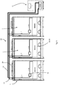
- FIG. 3 a further embodiment is shown.
- three cooling units 1 arranged at a distance from one another form a cooling system 22.
- the same reference numbers as before correspond to the same components and are not explained again here.
- Each of the cooling units 1 comprises both a cooling medium supply and discharge line 16, 18, as well as a pump arrangement 14 and also a control device 24.
- the medium lines 16, 18 with the central line sections 12, 13 do not have any control units connected.
- the line sections 12, 13 in turn form the line network with a cold generator, for. B. a heat pump 11, from.
- Each cooling unit 1 comprises an internal cooling medium network and a control device 24, which advantageously regulates and / or controls the output of the pump arrangement 14.
- the cooling medium entering the cooling unit 1 first flows through the pump arrangement 14 in order to then be transferred to the heat exchanger 20. After flowing through the heat exchanger 20, the cooling medium is transported via the cooling medium discharge line 18 to the line section 13 and exits the cooling unit 1 again.
- Fig. 4 a modification is shown, where the same reference numerals as above correspond to the same components.
- the cooling unit 1 shown here also includes power electronics 14a.
- shut-off valves 25 are also provided within the cooling unit 1, which control the cooling medium flow.
- Fig. 5 differs from this in that, in addition, throttle elements 15, e.g. B. throttle bodies are provided with associated power electronics 15a.
- the power electronics 15a are advantageously designed as a servomotor.
- the servomotor which is assigned to each throttle element 15, is responsible for adjusting the throttle element 15, for example in order to adjust the coolant flow.
- Fig. 6 corresponds to the structure Fig. 3
- throttle element 15 are arranged in each cooling unit 1. These are used to fine-tune requirements.
- the cooling system 22 shown also comprises a single pump arrangement 14 which is arranged within a cooling unit.
- FIG. 7 Another embodiment is shown with throttle elements 15, the pump arrangement 14 being arranged here within the heat pump. This is also advantageous in order to keep the pump arrangement free of ice and / or free of condensate.
- FIG. 11 shows a schematic side view of a cooling unit 1, the same reference numerals as in FIG Fig. 1 correspond to the same components and are not explained again here.
- the bottom element 6 is here trough-shaped in the front area, advantageously opposite the back wall 4.
- the recess serves as a condensate trap and / or as a coolant trap for maintenance work.
- the rear wall 4 is also conceivable to form the rear wall 4 from different materials so that, for example, an upper
- the rear wall section 4a has a different insulation property than the lower rear wall section 4b.
- the arrangement of the regulating element 14, advantageously a high-efficiency pump, has proven to be advantageous in the lower third of the cooling unit 1 due to the control of the regulating and / or monitoring function.
- the two cooling medium lines 16, 18 run within the cooling unit 14 and only connect the outside of the ceiling element 2 to the line sections 12, 13 in a medium-tight connection. This ensures that the continuous flow of cooling medium between the cooling units 1 is ensured within the entire cooling system 22, which comprises a plurality of cooling units 1.
- the in Figure 8a The cooling unit 1 shown still has storage shelves 26 and an exit area 30 from which the cold air flow exits like a curtain and falls downwards following gravity.
- FIG 8b , c show further exemplary embodiments of the cooling unit 1, the cooling medium lines 12 and 13 being integral components of the cooling space. This means that the line sections 12 and 13 are introduced into the insulation or the insulation of the rear wall 4 or of the ceiling element 2.
- Fig. 9 finally shows yet another embodiment.
- the cooling units 1 are designed as cooling spaces.
- the arrangements of the individual components within the refrigeration rooms are different from the example refrigeration units listed above.
- Each cooling unit, here each cooling space comprises, in addition to a pump arrangement 14 and a control device 24, also at least one sensor element 38, advantageously for temperature detection. Also the one shown here
- the cooling system 22 is connected to a heat pump 11 via the line network.
- cooling unit 1 is designed as a cooling unit module which can be arranged individually and / or in combination with further cooling module units 1.
- several cooling units 1 form components of a cooling system 22.
- the same reference numerals as in the previous figures correspond to the same components and are not explained again here.
- the embodiment of the cooling unit 1 shown here comprises an insulation unit 36 which is arranged on the upper side of the cooling unit 1.
- This arrangement can be fixed and / or detachable, so that the insulation unit 36 can also be exchanged easily.
- the insulation unit 36 is firmly connected to the ceiling element 2.
- the pump arrangement 14 is arranged within the insulation unit 36, which is advantageously formed from insulation material 40, more advantageously from at least one polymer foam, even more advantageously from at least one expanded polypropylene.
- the pump arrangement 14 is in the flow direction of the cooling medium a shut-off valve 25 arranged upstream. This regulates the flow of the cooling medium and can also completely prevent it, for example during repairs or transport.
- Another shut-off valve 25 is also arranged in the insulation unit 36 in the outflow direction of the cooling medium.
- connection of the insulation unit 36 with the cooling unit 1 in that both components have a common opening 42.
- the opening 42 can advantageously be designed as a connection between the interior volume of the insulation unit 36 and the interior of the cooling unit 1. In this case, possible condensate can flow directly out of the insulation unit 36 via its inclined bottom surface 44 and be removed via the cooling unit 1.
- the condensate collecting channel comprises a little one depression, which is advantageously designed as a groove in which the condensate collects.
- the opening is designed to be reversibly closable with a closure cap, for example with a solenoid valve, a tilting flap or a control flap (not shown) so that the flap opens automatically depending on the amount of condensate and / or the weight of the condensate to allow the condensate to flow off and then automatically close and seal again.
- the condensate is discharged to the cooling medium lines in an offset manner in order to prevent them from corroding avoid.
- the cooling medium lines in the inlet and / or outlet area on the insulation unit 36 are provided with sealing elements (not shown) which close them off in a liquid-tight and / or gas-tight manner.
- the condensate collecting channel and / or the inclined floor area 44 can advantageously be formed from a further material, for example from a water-resistant and / or water-repellent organic and / or inorganic coating, for example from at least one polymer, at least one block copolymer, at least one surfactant, at least one sol or at least one sol-gel composition and / or a mixture thereof.
- the organic coating can also advantageously comprise at least one halogen, for example fluorine.
- the at least one coating material is advantageously hydrophobic, more advantageously superhydrophobic, so that on the one hand a large contact angle of greater than and / or equal to 90 ° is established and consequently only small wetting areas are formed between the condensate and the coating material.
Landscapes
- Engineering & Computer Science (AREA)
- Thermal Sciences (AREA)
- Physics & Mathematics (AREA)
- General Engineering & Computer Science (AREA)
- Combustion & Propulsion (AREA)
- Mechanical Engineering (AREA)
- Chemical & Material Sciences (AREA)
- Devices That Are Associated With Refrigeration Equipment (AREA)
- Fluid-Pressure Circuits (AREA)
- Air Conditioning Control Device (AREA)
- Beans For Foods Or Fodder (AREA)
- Cold Air Circulating Systems And Constructional Details In Refrigerators (AREA)
- Other Air-Conditioning Systems (AREA)
Description
Die Erfindung betrifft eine Kühleinheit, insbesondere zum Kühlen von Lebensmitteln.The invention relates to a cooling unit, in particular for cooling food.
Aus dem Stand der Technik sind handelsübliche Kühleinheiten in Form von Kühlregalen bekannt, welche beispielsweise in Supermärkten zur Kühlung von frischen Lebensmitteln im Plusgradbereich, wie beispielsweise Wurst oder Käse, vorgesehen sind.Commercially available cooling units in the form of cooling shelves are known from the prior art, which are provided, for example, in supermarkets for cooling fresh food in the plus degree range, such as sausage or cheese.
Handelsübliche Kühlregale weisen eine Rückwand, eine Bodenplatte und eine Deckplatte auf, so dass sich zwischen diesen Bauteilen ein zumindest teilweise offener zu kühlender Warenraum aufspannt.Commercial refrigerated shelves have a rear wall, a base plate and a cover plate, so that an at least partially open goods space to be cooled is spanned between these components.
Um überhaupt nun eine Kühlung zu ermöglichen, werden außerhalb der Kühleinheit, die entsprechenden Kühlmediumzuführleitungen bzw. Kühlmediumabführleitungen mit den entsprechenden Drosselorganen vorgesehen, so dass auf Grund der Erwärmung des Kälteträgermediums im zu kühlenden Warenraum Wärme aus diesem entzogen werden kann.In order to enable cooling at all, the corresponding cooling medium supply lines or cooling medium discharge lines with the corresponding throttling devices are provided outside the cooling unit, so that heat can be extracted from it due to the heating of the coolant in the goods space to be cooled.
Bei der Verlegung von zentralen Zuführleitungen bzw. Abführleitungen des Kühlmediums zur Kühleinheit hin bzw. von dieser weg bedarf es stets einer aufwändigen und komplexen Dämmung oder Isolierung der Rohrleitungen. Diese Dämmung verhindert, dass sich an den Zuführleitungen bzw. Abführleitungen, die mit einem Kühlmedium durchströmt werden, Kondensat bildet und die Leitungen außerhalb des zu kühlenden Warenraumes vereisen.When laying central supply lines or discharge lines for the cooling medium to or from the cooling unit, expensive and complex insulation or insulation of the pipelines is always required. This insulation prevents condensate from forming on the supply lines or discharge lines through which a cooling medium flows and the lines outside the goods area to be cooled from icing up.
Weiterhin sind im Außenbereich der Kühleinheit, beispielsweise an der Außenfläche der Deckplatte, Drosselorgane zum Regeln des Massenstroms und somit auch zur Wärmeentzugsleistung vom zu kühlende Warenraum vorgesehen.Furthermore, in the outer area of the cooling unit, for example on the outer surface of the cover plate, throttle elements for regulating the mass flow and thus also for extracting heat from the goods space to be cooled are provided.
Nachteil dieser Technik ist, dass insbesondere an den Drosselorganen stetig Feuchtigkeit kondensiert, welche als Folge vereisen und in ihrer Funktion beeinträchtigt bzw. vollkommen unbrauchbar sind. Ferner erweist sich das flüssige Kondensat an den Drosselorganen, welche selbst dämmungsfrei ausgebildet sind, und/oder im Bereich um die Drosselorgane, welcher ebenfalls dämmungsfrei aufgrund der bautechnischen Fixierungsmaßnahmen zwischen Kühlmediumsleitungen und Drosselorgan, ausgebildet ist, für die an diesen dämmungsfreien Bereich anschließende Dämmung nachteilig, da sich die Dämmung schwammartig mit Wasser vollsaugt, wodurch die Leitungskorrosion deutlich beschleunigt wird. Zudem bedingt die Durchnässung der Kühlmediumzuführleitungen bzw. Kühlmediumabführleitungen auch immer den Verlust deren Isolationseigenhaft. Aufgrund der Konstruktion bekannter Kühleinheiten ist es, wie oben erwähnt, immer notwendig eine Isolierung und/oder Dämmung der Kühlmediumsleitungen vorzusehen. Allerdings wird diese Dämmung durch die Drosselorgane unterbrochen, welche beispielsweise an den Leitungen angeflanscht sind. Folglich ist es nicht möglich, die Drosselorgane selbst zu dämmen. Auch ist es nicht möglichen die nähere Umgebung der Drosselorgane zu dämmen, so dass die Drosselorgane sowie deren Umfeld dämmungsfrei ausgebildet sind und sich gerade hier Kondensat niederschlägt und gefriert. Aufgrund der Eisbildung und der damit einhergehenden Funktionseinschränkung der Drosselorgane, bedarf es bei bekannten Kühleinheiten aufwändiger Abtauschritte und langer Abtauzeiten, um die Drosselorgane wieder abzutauen. Während dieser Abtauschritte ist selbstverständlich keine Kühlung des Kühlgutes möglich, so dass Warenverluste zu jeder Zeit in Kauf zu nehmen sind. Des Weiteren wird aufgrund der Durchnässung der Dämmung dieses dauerhaft beschädigt, so dass die Dämmungswirkung verloren geht und aufwändig nachgedämmt werden muss. Ferner bedingt der Stand der Technik nachteilig, dass direkt unterhalb der Drosselorgane zusätzliche Tropfwannen eingepasst werden müssen, um das Abtauwasser aufzufangen und dieses abzuführen
Demzufolge liegt der vorliegenden Erfindung die Aufgabe zu Grunde, eine Kühleinheit zur Verfügung zu stellen, deren Regeleinheit aus dem Stand der Technik bekannte Eisbildung an den Drosselorganen und/oder eine Durchnässung der Dämmung vermeiden.Accordingly, the present invention is based on the object of providing a cooling unit, the control unit of which prevents the formation of ice on the throttling elements and / or of the insulation, known from the prior art, from being soaked through.
Diese Aufgabe wird gemäß den Merkmalen des Patentanspruches 1 gelöst.This object is achieved according to the features of
Ein wesentlicher Punkt der Erfindung nach Patentanspruch 1 liegt darin, dass die Regeleinheit innerhalb der Kühleinheit angeordnet ist. Dies hat im Wesentlichen den Vorteil, dass eine Vereisung wie bei bekannten Drosselorganen aus dem Stand der Technik vermieden wird. Die Regeleinheit der vorliegenden Erfindung ist somit dauerhaft eisfrei ausgebildet. Zudem ist diese Anordnung von Vorteil, da die zentralen Kühlmediumszuführ- und/oder -abführleitungen durch die Regeleinheiten innerhalb der Kühleinheit vollständig isoliert ausgebildet werden können, ohne dass das Dämmmaterial, wie bei bekannten Kühleinheiten durch die Drosselorgane unterbrochen wird. Weiterhin von Vorteil weist die Regeleinheit während des Betriebs eine Eigentemperatur im Bereich von -20°C bis 25°C, vorteilhafter in Abhängigkeit der Kühlraumtemperatur im Bereich von 0,25 K bis 20 K höher als die Kühlraumtemperatur auf, so dass während des Betriebs der Regeleinheit, welcher auch zugleich dem Betrieb der Kühleinheit entspricht, die Temperatur der Regeleinheit stets gleich oder höher ist als die Temperatur des verflüssigten Kühlmediums und/oder des expandierten Kühlmediums.An essential point of the invention according to
Zur vereinfachten Abführung von Kondenswasser der Regeleinheit, welches sich eventuell bei extrem hoher Luftfeuchtigkeit dennoch bilden kann, kann zwischen der Regeleinheit und dem Bodenelement ein Freiraum bedingt sein, welcher keine relevanten, insbesondere elektronischen, Bauteile der Kühleinheit aufweist. Hierdurch wird sichergestellt, dass das Kondensat an den Kühlmediumsleitungen oder auch direkt an der Regeleinheit selbst nach unten in Richtung Bodenelement abtropfen kann und somit vorteilhaft bekannte Korrosionen, Rostbildungen und elektronische Schäden auf Grund von Wasser (Kondensat/Eis) gänzlich vermieden werden. Dies ist besonders vorteilhaft für die Laufzeit der Kühleinheit sowie die damit deutlich reduzierten Wartungsintervalle. Ferner erweist sich diese Anordnung zudem kostengünstiger, da weniger Bauteile verschlissen werden.To simplify the discharge of condensation water from the control unit, which may still form at extremely high humidity, a free space can be required between the control unit and the floor element, which has no relevant, in particular electronic, components of the cooling unit. This ensures that the condensate on the cooling medium lines or directly on the control unit itself can drip down in the direction of the floor element and thus advantageously known corrosion, rust formation and electronic damage due to water (condensate / ice) are completely avoided. This is particularly advantageous for the running time of the cooling unit as well as the significantly reduced maintenance intervals. This arrangement also turns out to be also more cost-effective, as fewer components are worn.
Ein weiterer Vorteil des Bodenelements besteht darin, dass dieses im Wartungsfall auch dazu geeignet ist, Kühlmedium aufzufangen und das Kühlmedium über den Abfluss abzuführen, so dass ein Verschmutzen der Kühleinheit selbst vermieden wird.Another advantage of the floor element is that, in the event of maintenance, it is also suitable for collecting cooling medium and discharging the cooling medium via the drain, so that soiling of the cooling unit itself is avoided.
Ein wesentlicher Punkt der Erfindung nach Patentanspruch 1 liegt darin, dass die Regeleinheit innerhalb der Kühleinheit zumindest teilweise innerhalb einer Dämmungseinheit angeordnet ist. Diese Anordnung hat den Vorteil, dass die Regeleinheit hier zumindest teilweise, vorteilhaft vollständig, innerhalb einer Dämmungseinheit angeordnet ist. Dies ist insbesondere vorteilhaft, um die Regeleinheit von der Luftfeuchtigkeit der Raumluft zu isolieren, so dass zusätzlich ein Weg geschaffen, wird, Kondensat und Eisbildung zu vermeiden. Die Dämmungseinheit ist weiterhin vorteilhaft aus Dämmmaterial ausgebildet, beispielsweise aus wenigstens einem Polymerschaum, vorteilhafter aus expandiertem Polypropylen oder Polystyrol, so sich ein Temperaturgradient zwischen dem Innenvolumen der Dämmungseinheit und der Kühleinheit selbst bedingt. Vorteilhaft ist das Innenvolumen der Dämmungseinheit höher temperiert, als die außenliegende Umgebung. Folglich ist auch hier die Regeleinheit eisfrei und/oder vereisungsfrei ausgebildet.An essential point of the invention according to
Die hier beschriebenen Regeleinheiten sind vorteilhaft innerhalb einer Kühleinheit, noch vorteilhafter zumindest teilweise, am vorteilhaftesten im zu kühlenden Warenraum der Kühleinheit angeordnet.The control units described here are advantageous within a cooling unit, even more advantageously at least partially, most advantageously arranged in the goods space to be cooled of the cooling unit.
Ein Vorteil beider hier beschriebener Kühleinheiten nach Patentspruch 1 oder 2 besteht darin, dass die Kühleinheit hydraulisch optimal abgeglichen ist. Grundlage des hydraulischen Abgleichs ist eine entsprechende Auslegung des Kältenetzes über Rohrnetzberechnungsprogramme. Dabei muss die Kälteleistung der einzelnen Kühleinheiten, sowie die Druckverluste sämtlicher Komponenten des Rohrnetzes, bekannt sein. Im Stand der Technik fehlt der hydraulische Abgleich, so dass bestimmte Kühleinheiten, die dem Kälteerzeuger nahestehen, überversorgt und Kühleinheiten die dem Kälteerzeuger nicht nahestehen, unterversorgt werden. Unter Kälteversorger ist hierbei vorteilhaft eine Einrichtung zu verstehen, welche das Kühlmedium fördert, beispielsweise eine Wärmepumpe, deren Kühlmedium bzw. Kühlträger als Sole ausgewählt ist. Dies bedeutet, dass zur Kühlung der unterversorgten Kühleinheiten die Soletemperatur erniedrigt werden muss, so dass der Kälteerzeuger häufiger taktet. Des Weiteren bedeutet die Absenkung der Soletemperatur auch, dass die Solekonzentration erhöht werden muss, wodurch sich eine Verschlechterung des Wertes der spezifischen Wärmekapazität und folglich auch der Effizienz bedingt. Mit der hier beschriebenen Regeleinheit werden genau diese Nachteile des Standes der Technik überwunden und ein optimaler hydraulischer Abgleich erzeugt.An advantage of both cooling units described here according to
Weitere vorteilhafte Ausführungen sind in den Unteransprüchen aufgeführt.Further advantageous designs are listed in the subclaims.
Erfindungsgemäß ist die Regeleinheit als Pumpenanordnung ausgebildet. Ein Vorteil der Pumpenanordnung besteht darin, dass diese während des Betriebs Wärmeenergie abgibt. Diese Eigenwärme verhindert, dass die Pumpenanordnung selbst schwitzt oder vereist. Ein weiterer Vorteil ist zudem, dass die Taupunkttemperatur aufgrund der Eigenerwärmung bei elektrischen Regeleinheiten, insbesondere von einer Pumpenanordnung, angehoben wird. Dies bedeutet, dass aufgrund der Eigenerwärmung der Regeleinheit die Temperatur, insbesondere im Gehäuse der Pumpenanordnung, auf eine Temperatur angehoben wird, so dass sich keine Feuchtigkeit innerhalb des Gehäuses der Pumpe niederschlagen kann. Folglich liegt während des Betriebs der Pumpenanordnung, was auch dem Betrieb der Kühleinheit entspricht, die Temperatur im und/oder am Gehäuse der Pumpenanordnung stets höher ist als die Taupunkttemperatur im zu kühlenden Warenraum.According to the invention, the control unit is designed as a pump arrangement. An advantage of the The pump arrangement consists in the fact that it emits thermal energy during operation. This inherent heat prevents the pump arrangement itself from sweating or icing up. Another advantage is that the dew point temperature is increased due to the self-heating in electrical control units, in particular by a pump arrangement. This means that due to the self-heating of the control unit, the temperature, in particular in the housing of the pump arrangement, is raised to a temperature so that no moisture can precipitate inside the housing of the pump. Consequently, during the operation of the pump arrangement, which also corresponds to the operation of the cooling unit, the temperature in and / or on the housing of the pump arrangement is always higher than the dew point temperature in the goods space to be cooled.
Darüber hinaus erweist sich das Vorsehen einer Pumpenanordnung pro Kühlstelle dahin gehend als vorteilhaft, da hierdurch auch Pumpenanordnungen mit einer geringeren Leistung einsetzbar sind. Diese dezentrale Einzelanordnung ist zudem vorteilhaft, da hierdurch jede Kühleinheit individuell regelbar ausgebildet ist, so dass jede Kühleinheit beispielsweise in Abhängigkeit der zu kühlenden Waren in der Kühltemperatur variabel einstellbar ist.In addition, the provision of a pump arrangement per cooling point has proven to be advantageous in that it also enables pump arrangements with a lower output to be used. This decentralized individual arrangement is also advantageous because it allows each cooling unit to be individually regulated, so that the cooling temperature of each cooling unit can be variably adjusted, for example, depending on the goods to be cooled.
Das Vorsehen von wenigstens einer Pumpenanordnung pro Kühleinheit bedingt außerdem einen idealen hydraulischen Abgleich, wie oben ausgeführt, so dass jede Pumpenanordnung stets nur so viel Förderhöhe erbringt, wie auch tatsächlich von der jeweiligen Kühleinheit benötigt wird.The provision of at least one pump arrangement per cooling unit also requires ideal hydraulic balancing, as explained above, so that each pump arrangement always only provides as much delivery head as is actually required by the respective cooling unit.
Hierbei ist die Pumpenanordnung derart ausgebildet, dass diese vorteilhaft dauerhaft den Druckverlust des Wärmeentzugsüberträgers sowie der Zuführleitung bzw. Abführleitung, die mit dem Kühlmedium durchströmt werden, überwindet.In this case, the pump arrangement is designed in such a way that it advantageously permanently reduces the pressure loss of the heat extraction transmitter as well as the supply line or discharge line through which the cooling medium flows.
Zudem besteht die Möglichkeit die Regeleinheit, vorteilhaft die Pumpenanordnung, zusätzlich und/oder alternativ in den Belüftungsstrom des Wärmeaustauschers der Kühleinheit anzuordnen, so dass die Regeleinheit zumindest während des Betriebs zusätzlich mittels des Belüftungsstromes des Wärmeaustauschers schwitzwasserfrei oder/und eisfrei ausgebildet ist.In addition, there is the possibility of arranging the control unit, advantageously the pump arrangement, in addition and / or alternatively in the ventilation flow of the heat exchanger of the cooling unit, so that the control unit is designed to be free of condensation water and / or ice at least during operation by means of the ventilation flow of the heat exchanger.
Ferner besteht auch die Möglichkeit, um die Pumpenanordnung kondensatfrei oder/und eisfrei zu halten, in dem die Regeleinheit zusätzlich innerhalb der Kühleinheit zu dämmen und/oder zu isolieren. Dies kann beispielsweise mit einer einfachen Dämmungseinheit erfolgen, welche die Regeleinheit umschließt. Im einfachsten Fall kann die Dämmungseinheit lediglich temperaturisolierend ausgebildet sein. Alternativ wäre auch denkbar, die Dämmungseinheit diffusionsdicht auszubilden.Furthermore, there is also the possibility of keeping the pump arrangement free of condensate and / or ice by additionally insulating and / or insulating the control unit within the cooling unit. This can be done, for example, with a simple insulation unit that encloses the control unit. In the simplest case, the insulation unit can only be designed to be temperature-insulating. Alternatively, it would also be conceivable to design the insulation unit to be diffusion-tight.
Ferner wird bei einer weiteren vorteilhaften Ausführungsform die Pumpenanordnung als Hocheffizienzpumpe ausgebildet. Dies ist von Vorteil, da durch geregelte Hocheffizienzpumpe ein bedarfsgerechte Massenstrom des Kühlmediums gefördert wird und hierdurch eine gleichmäßige, kontinuierliche Fließgeschwindigkeit des Kühlmediums innerhalb der Kühleinheit bei höher energetischer Effizienz ermöglicht wird.Furthermore, in a further advantageous embodiment, the pump arrangement is designed as a high-efficiency pump. This is advantageous because a regulated high-efficiency pump promotes a needs-based mass flow of the cooling medium and this enables a uniform, continuous flow rate of the cooling medium within the cooling unit with higher energy efficiency.
Dies ist selbstverständlich nicht beschränkend zu verstehen, so dass es auch denkbar ist, pro Kühleinheit mehrere Pumpenanordnungen vorzusehen.Of course, this is not to be understood as restrictive, so that it is also conceivable to provide several pump arrangements per cooling unit.
Insbesondere die Ausbildung der Regeleinheit als Pumpenanordnung ist dahingehend vorteilhaft, da somit der Druckverlust des Kühlmediumsnetzes einer Kühleinheit deutlich reduziert werden kann. Zum Beispiel bedingt das Vorsehen einer zentralen Kühlmediumsförderpumpe und wie aus dem Stand der Technik bekannt angeordneten Drosselorganen, dass durch die Forderung nach einer effektiven Ventilautorität (PVeff) bei dem Kühlmediumsnetz mit einer zentralen Kühlmediumsförderpumpe ein deutlich höherer Förderdruck bereitgestellt werden muss. Folglich müsste für eine effektive Ventilautorität von mindestens 0,4 der bereitzustellende Gesamtdruck um 67% erhöht werden, im Vergleich zu einem Kühlmediumsnetz bei dem der Massenstrom pro Kühleinheit durch jeweils eine Pumpenanordnung geregelt wird.In particular, the design of the control unit as a pump arrangement is advantageous in that the pressure loss in the cooling medium network of a cooling unit can be significantly reduced. For example, the provision of a central cooling medium feed pump and throttling devices arranged as is known from the prior art means that a significantly higher feed pressure must be provided due to the requirement for an effective valve authority (P Veff ) in the cooling medium network with a central cooling medium feed pump. Consequently, for an effective valve authority of at least 0.4, the total pressure to be provided would have to be increased by 67% compared to a cooling medium network in which the mass flow per cooling unit is controlled by a pump arrangement.
Nach einem Beispiel, das nicht Teil der beanspruchten Erfindung ist, ist die Regeleinheit als Regelorgan ausgebildet, vorteilhaft umfassend mehrere Drosselorgane und wenigstens eine Pumpenanordnung. So können die Drosselorgane beispielsweise als aus der Gruppe 2-Punkt-Ventile, 2-Wege-Ventile, 3-Wege-Ventile und/oder Strangregulierventile ausgewählt sein.According to an example that is not part of the claimed invention, the control unit is designed as a control element, advantageously comprising several throttle elements and at least one pump arrangement. For example, the throttling elements can be selected from the group consisting of 2-point valves, 2-way valves, 3-way valves and / or balancing valves.
Zudem besteht die Möglichkeit das Drosselorgan zusätzlich und/oder alternativ in den Belüftungsstrom des Wärmeaustauschers der Kühleinheit anzuordnen, so dass das Drosselorgan zumindest während des Betriebs der Kühleinheit zusätzlich mittels des Belüftungsstromes des Wärmeaustauschers schwitzwasserfrei oder/und eisfrei ausgebildet ist.In addition, there is the possibility of arranging the throttle element additionally and / or alternatively in the ventilation flow of the heat exchanger of the cooling unit, so that the throttle element is also free of condensation water and / or ice-free by means of the ventilation flow of the heat exchanger, at least during operation of the cooling unit.
So kann vorteilhaft die Regeleinheit als Pumpenanordnung und/oder auch als Drosselorgan mit einer zentralen Kühlmediumsförderpumpe im zu kühlenden Warenraum ausgebildet sein. So ist beispielsweise denkbar, dass innerhalb der Kühleinheit, vorteilhafter innerhalb des zu kühlenden Warenraumes Pumpenanordnungen und/oder Drosselorgan und/oder Kombinationen hieraus angeordnet sind, wobei die Drosselorgan vorteilhaft aus der Gruppe 2-Punkt-Ventile, 2-Wege-Ventile, 3-Wege-Ventile und/oder Strangregulierventile ausgewählt werden. Insbesondere die Pumpenanordnung innerhalb einer jeden Kühleinheit, vorteilhafter innerhalb eines jeden Kühlraumes, hat sich als effektiv und verlässlich erwiesen, da die Pumpenanordnung stets eisfrei bleibt.Thus, the control unit can advantageously be designed as a pump arrangement and / or also as a throttle element with a central cooling medium feed pump in the goods space to be cooled. For example, it is conceivable that within the cooling unit, pump assemblies and / or throttle elements and / or combinations thereof are advantageously arranged within the goods space to be cooled, the throttle elements advantageously being selected from the group of 2-point valves, 2-way valves, 3-way valves and / or balancing valves. In particular, the pump arrangement within each cooling unit, more advantageously within each cooling space, has proven to be effective and reliable, since the pump arrangement always remains free of ice.
Ferner ist denkbar, dass die hier beschriebenen Kühleinheiten auch wenigstens eine lokale Steuereinrichtung umfassen, welche beispielsweise die Fördermenge der Pumpenanordnung oder den Massenstrom des Drosselorgans regelt und/oder kontrolliert. Diese Steuereinrichtung kann sowohl in der Pumpenanordnung und/oder dem Drosselorgan integriert sein und/oder separat in der Kühleinheit und/oder außerhalb der Kühleinheit angeordnet sein. Des Weiteren ist die Steuereinrichtung vorteilhaft derart ausgebildet, dass sie die lokalen Regeleinheiten innerhalb der Kühleinheit ansteuert und zudem bei Bedarf die Förderhöhe der zentralen Kühlmediumsförderpumpe und/oder dezentralen Pumpenanordnung erhöht oder reduziert.Furthermore, it is conceivable that the cooling units described here also comprise at least one local control device which regulates and / or controls, for example, the delivery rate of the pump arrangement or the mass flow of the throttle element. This control device can be integrated both in the pump arrangement and / or the throttle element and / or arranged separately in the cooling unit and / or outside the cooling unit. Furthermore, the control device is advantageously designed in such a way that it controls the local control units within the cooling unit and, if necessary, also increases or reduces the delivery height of the central cooling medium delivery pump and / or decentralized pump arrangement.
Bei einer weiteren vorteilhaften Ausführungsform ist die Regeleinheit über wenigstens ein Sensorelement regelbar ausgebildet. Dies ist vorteilhaft, da somit in Abhängigkeit des Kühlmediums, der Zufuhr des Kühlmediums, dessen Temperatur und/oder dessen Drucks die Regeleinheit, insbesondere die Pumpenanordnung, entsprechend individuell steuerbar ist, um einen Druckausgleich und/oder einen Temperaturausgleich/- angleich vorzunehmen. Vorteilhaft ist das Sensorelement als Messfühler ausgebildet und über wenigstens eine Schnittstelle mit der Regeleinheit, vorteilhaft der Pumpenanordnung, und/oder der Steuereinrichtung verbunden. Die Schnittstelle ist vorteilhaft als Bus ausgebildet, noch vorteilhafter als Modbus und/oder als PWM-Signal und/oder als eine 0 bis 10 Volt Schnittstelle.In a further advantageous embodiment, the control unit is designed to be controllable via at least one sensor element. This is advantageous because, depending on the cooling medium, the supply of the cooling medium, its temperature and / or its pressure, the control unit, in particular the pump arrangement, can be individually controlled in order to carry out pressure compensation and / or temperature compensation. The sensor element is advantageously designed as a measuring sensor and has at least one interface connected to the control unit, advantageously the pump arrangement, and / or the control device. The interface is advantageously designed as a bus, even more advantageously than Modbus and / or as a PWM signal and / or as a 0 to 10 volt interface.
Insbesondere hat es sich als vorteilhaft erwiesen, zwei Sensorelemente in Flussrichtung des Kühlmediums, also des Kälteträgers, vor und nach der Regeleinheit vorzusehen, wobei beide Sensorelemente vorteilhaft im gleichen Abstand zur Regeleinheit angeordnet sind. Dies ermöglicht eine verlässliche Kontrolle des Massenstromes des Kühlmediums. Vorteilhaft sind beide Sensoren über jeweils eine Schnittstelle mit der Regeleinheit verbunden. Dies kann kabelgebunden und/oder kabelfrei, beispielsweise über Funk oder RFID erfolgen. So ist beispielsweise denkbar, dass die von den Sensorelementen erfassten Daten drahtlos an die Regeleinheit und/oder an die Steuereinrichtung übermittelt und dort verarbeitet zu werden. Alternativ wäre auch denkbar, dass die Regeleinheit und/oder die Steuereinrichtung die von den Sensorelementen erfassten Daten in vorbestimmbaren Zeitintervallen von diesen zur Weiterverarbeitung abholen.In particular, it has proven to be advantageous to provide two sensor elements in the flow direction of the cooling medium, that is to say of the refrigerant, upstream and downstream of the control unit, with both sensor elements advantageously being arranged at the same distance from the control unit. This enables a reliable control of the mass flow of the cooling medium. Both sensors are advantageously connected to the control unit via an interface each. This can be done in a wired and / or wireless manner, for example via radio or RFID. For example, it is conceivable that the data recorded by the sensor elements are transmitted wirelessly to the control unit and / or to the control device and processed there. Alternatively, it would also be conceivable that the regulating unit and / or the control device fetch the data recorded by the sensor elements from them at predeterminable time intervals for further processing.
Erfindungsgemäß umfasst die Dämmungseinheit wenigstens eine erste Öffnung zum Durchführen der Kühlmediumszuführleitung in die Dämmungseinheit hinein und wenigstens eine weitere Öffnung zum Durchführen der Kühlmediumsabführleitung aus der Dämmeinheit heraus, wobei die Dämmungseinheit zusätzlich wenigstens einen Kondensatauffangkanal umfasst. Das Vorsehen einer Dämmungseinheit ist vorteilhaft, um die Regeleinheit auch im reduzierten Betrieb der Pumpenanordnung oder auch bei der Ausbildung der Regeleinheit als Drosselorgan mit einer zentralen Kühlmediumsförderpumpe nahezu eisfrei und/oder kondensatfrei zu halten.According to the invention, the insulation unit comprises at least one first opening for leading the cooling medium supply line into the insulation unit and at least one further opening for leading the cooling medium discharge line out of the insulation unit, the insulation unit additionally comprising at least one condensate collecting channel. The provision of an insulation unit is advantageous to the control unit in reduced operation of the pump arrangement or to keep almost ice-free and / or condensate-free even when the control unit is designed as a throttle device with a central cooling medium feed pump.
Vorteilhaft spannt die Dämmungseinheit einen geschlossenen Raum um die Regeleinheit auf, so dass die Dämmungswirkung der Dämmungseinheit genutzt wird. Im einfachsten Fall ist die Dämmungseinheit als Quader, Würfel oder auch als Kugel ausgebildet. Dies ist selbstverständlich nicht begrenzend zu verstehen, so dass auch jegliche andere polygonale Formen und Körper denkbar sind.The insulation unit advantageously spans a closed space around the control unit, so that the insulation effect of the insulation unit is used. In the simplest case, the insulation unit is designed as a parallelepiped, cube or also as a sphere. Of course, this is not to be understood as limiting, so that any other polygonal shapes and bodies are also conceivable.
Sollte sich dennoch an der Regeleinheit Kondensat bilden, so umfasst die Dämmungseinheit, welche vorteilhaft aus wenigstens einem Dämmmaterial ausgebildet ist, wenigstens einen Kondensatauffangkanal. Im einfachsten Fall ist dieser Kondensatauffangkanal als Vertiefung, beispielsweise als geneigte Rinne ausgebildet, so dass das Kondensat in wenigstens einem Auffangbereich der Dämmungseinheit, vorteilhaft an deren Boden, gesammelt wird und folglich leicht abgeführt werden kann.Should condensate nevertheless form on the control unit, then the insulation unit, which is advantageously formed from at least one insulation material, comprises at least one condensate collecting channel. In the simplest case, this condensate collecting channel is designed as a recess, for example as an inclined channel, so that the condensate is collected in at least one collecting area of the insulation unit, advantageously at its bottom, and can consequently be easily removed.
Vorteilhaft sind die Durchführungsöffnungen der Kühlmediumszuführ- und abführleitungen mit geeigneten Dichtungselementen feuchtigkeits- und/oder gasdicht ausgebildet.The feed-through openings of the cooling medium supply and discharge lines are advantageously made moisture-tight and / or gas-tight with suitable sealing elements.
Weiterhin vorteilhaft mündet der Kondensatauffangkanal in den Auffangbereich, welcher eine weitere Öffnung innerhalb der Wandung der Dämmungseinrichtung umfasst. Um nun hier ebenfalls die Feuchtigkeits- und/oder Gasdichtigkeit dieser Öffnung sicherzustellen, hat es sich als vorteilhaft erwiesen, die Öffnung mittels eines Ventils, beispielsweise eines Magnetventils, schlagartig zu öffnen, um das Kondensat schnell und vollständig aus der Dämmungseinheit abzuführen. Vorteilhaft erfolgt die Steuerung des Magnetventils in Abhängigkeit der Kondensatmenge und/oder des Kondensatgewichts. Für diese Erfassung sind entsprechende Sensorelemente vorgesehen. Ergänzend wäre denkbar, innerhalb der Dämmungseinheit eine Heizeinrichtung vorzusehen, um Kondensatbildung zu vermeiden und die Regeleinheit zu temperieren.The condensate collecting channel also advantageously opens into the collecting area, which comprises a further opening within the wall of the insulation device. In order to ensure the moisture and / or gas tightness of this opening, it has proven advantageous to suddenly open the opening by means of a valve, for example a solenoid valve, in order to remove the condensate quickly and completely removed from the insulation unit. The solenoid valve is advantageously controlled as a function of the amount of condensate and / or the weight of the condensate. Appropriate sensor elements are provided for this detection. In addition, it would be conceivable to provide a heating device within the insulation unit in order to avoid condensation and to regulate the temperature of the control unit.
Darüber hinaus ist auch denkbar, das Kondensat aus der Dämmungseinheit über eine Regelklappe und/oder Kippklappe abzuführen, welche dann anstelle des Magnetventils vorgesehen ist. Vorteilhaft sind diese beiden Klappen mechanisch und/oder elektronisch steuerbar, so dass in Abhängigkeit der Kondensatmenge und/oder des Kondensatgewichts ein automatisches Öffnen und/oder Schließen der Regelklappe und/oder Kippklappe erfolgt.In addition, it is also conceivable to discharge the condensate from the insulation unit via a control flap and / or tilt flap, which is then provided instead of the solenoid valve. These two flaps can advantageously be controlled mechanically and / or electronically, so that the control flap and / or tilt flap are automatically opened and / or closed as a function of the amount of condensate and / or the weight of the condensate.
Darüber hinaus ist denkbar, eine weitere Fördereinrichtung, beispielsweise eine zusätzliche Pumpe, innerhalb der Dämmungseinheit anzuordnen, welche das Kondensat im Auffangbereich der Dämmungseinheit abpumpt. Vorteilhaft ist die Pumpe hierbei innerhalb der Dämmungseinheit angeordnet. Alternativ ist ebenfalls denkbar, das Kondensat im Auffangbereich von außen her abzusaugen. Hierbei ist vorteilhaft die Saugeinrichtung, beispielsweise eine Pumpe, außerhalb der Dämmungseinheit angeordnet. Beide Pumpen sind derart voreingestellt, dass sie in Abhängigkeit der Kondensatmenge und/oder des Kondensatgewichts die entsprechende Leistung direkt erbringen und das Kondensat aus der Dämmungseinheit aktiv abführen. Hierzu könnten vorteilhaft Messfühler oder andere Sensorelemente innerhalb der Dämmungseinheit, vorteilhaft im und/oder am Auffangbereich der Dämmungseinheit und/oder am und/oder im Kondensatauffangkanal angeordnet sein.In addition, it is conceivable to arrange a further conveying device, for example an additional pump, within the insulation unit, which pumps off the condensate in the collecting area of the insulation unit. The pump is advantageously arranged within the insulation unit. Alternatively, it is also conceivable to suck off the condensate from the outside in the collecting area. Here, the suction device, for example a pump, is advantageously arranged outside the insulation unit. Both pumps are preset in such a way that, depending on the amount of condensate and / or the weight of the condensate, they provide the corresponding output directly and actively discharge the condensate from the insulation unit. For this purpose, measuring sensors or other sensor elements could advantageously be located within the insulation unit, advantageously in and / or on the collecting area of the Insulation unit and / or be arranged on and / or in the condensate collecting channel.
Vorteilhaft sind hier Dämmungseinheit und Dämmungseinrichtung synonym verwendbar. Weiterhin hat sich gezeigt, dass es besonders vorteilhaft ist, die Dämmungseinheit aus expandiertem Polypropylen auszubilden. Dieses Material ist besonders leicht und in jeder beliebigen Form herzustellen.The insulation unit and the insulation device can advantageously be used synonymously here. Furthermore, it has been shown that it is particularly advantageous to make the insulation unit from expanded polypropylene. This material is particularly light and can be produced in any shape.
Weiterhin ist es vorteilhaft, die Dämmungseinheit zumindest teilweise am und/oder im oberen Deckenelement der Kühleinheit vorzusehen. Dies ist von Vorteil, da dann die Abführung des Kondensats aus der Dämmeinrichtung über die Kühleinheit erfolgen kann. Folglich werden aufwändige Leitungssysteme vermieden. Die Dämmungseinheit ist vorteilhaft als Bestandteil der Kühleinheit vorgesehen und kann beispielsweise auch einteilig mit dieser ausgebildet sein.Furthermore, it is advantageous to provide the insulation unit at least partially on and / or in the upper ceiling element of the cooling unit. This is advantageous because the condensate can then be discharged from the insulating device via the cooling unit. As a result, complex pipe systems are avoided. The insulation unit is advantageously provided as a component of the cooling unit and can, for example, also be formed in one piece with it.
Bei einer weiteren vorteilhaften Ausführungsform ist es denkbar, die Regeleinheit in einem weiteren, zusätzlichen Gehäuseabschnitt innerhalb der Kühleinheit anzuordnen, wobei dieser Gehäuseabschnitt alternativ oder in Ergänzung zu der Dämmungseinheit vorgesehen sein kann. Dies ist vorteilhaft, da durch den Gehäuseabschnitt, welcher vorteilhaft nach unten in Richtung Bodenelement geöffnet ausgebildet ist, eine zusätzliche Fixierung der Regeleinheit vorgesehen ist. Darüber hinaus dient der Gehäuseabschnitt weiterhin zur Geräuschreduzierung. Vorteilhaft ist der Gehäuseabschnitt an der Rückenwandung der Kühleinheit angeordnet, beispielsweise mit dieser verschraubt. Ferner kann der Gehäuseabschnitt auch als Sichtblende ausgebildet sein, so dass er beispielsweise die an der Kühleinheitrückenwandung angeordnete Regeleinheit vorteilhaft vollständig überspannt, wobei die Sichtblende beispielsweise plattenförmig oder auch als C-Profil ausgebildet sein kann. Die Funktion der Regeleinheit wird hierdurch nicht beeinträchtigt.In a further advantageous embodiment, it is conceivable to arrange the control unit in a further, additional housing section within the cooling unit, this housing section being able to be provided as an alternative to or in addition to the insulation unit. This is advantageous because the housing section, which is advantageously designed to be open downward in the direction of the base element, provides an additional fixation of the control unit. In addition, the housing section also serves to reduce noise. The housing section is advantageously arranged on the back wall of the cooling unit, for example screwed to it. Furthermore, the housing section can also be designed as a screen so that, for example, it advantageously completely covers the control unit arranged on the back wall of the cooling unit spanned, wherein the screen can be designed, for example, plate-shaped or as a C-profile. This does not affect the function of the control unit.
Ferner ist denkbar, innerhalb des Gehäuseabschnittes weitere Steuerungseinrichtungen oder Kontrolleinrichtungen vorzusehen, so dass der weitere Gehäuseabschnitt als dezentrale Kontrolleinheit ausgebildet ist. Vorteilhaft erfolgt die gesamte Steuerung der Kühleinheit über diese Kontrolleinheit. Vorteilhaft umfasst jede Kühleinheit weiterhin wenigstens eine Stromversorgung.It is also conceivable to provide further control devices or control devices within the housing section, so that the further housing section is designed as a decentralized control unit. The entire control of the cooling unit is advantageously carried out via this control unit. Each cooling unit advantageously further comprises at least one power supply.
Ist bei einer Kühleinheit kein entsprechender Gehäuseabschnitt vorgesehen, so ist die Regeleinheit an der Kühleinheit vorteilhaft fest fixiert, so dass diese beispielsweise während des Transports keinen Schaden nimmt.If no corresponding housing section is provided in a cooling unit, the control unit is advantageously firmly fixed to the cooling unit so that it is not damaged, for example, during transport.
Es hat sich zudem als vorteilhaft erwiesen, die Regeleinheit an der Rückenwandung, noch vorteilhafter im unteren Drittel der Rückenwandung der Kühleinheit zum Kühlraum hingerichtet anzuordnen. Dies ist von Vorteil, da hierdurch der Einfluss der Verwirbelung des Luftstromes, welcher von der als Pumpenanordnung ausgebildeten Regeleinheit erzeugt wird, deutlich reduziert wird. Wird die Regeleinheit, vorteilhafter die Pumpenanordnung zu weit oben in der Kühleinheit angeordnet, so kann dies insbesondere bei offenen Kühleinheiten den Nachteil bringen, dass der Kühlschleier unterbrochen wird und sich Ungleichmäßigkeiten in der Kühlung der Ware bedingen.It has also proven to be advantageous to arrange the control unit on the back wall, more advantageously in the lower third of the back wall of the cooling unit facing the cooling space. This is of advantage because it significantly reduces the influence of the turbulence in the air flow, which is generated by the control unit designed as a pump arrangement. If the control unit, more advantageously the pump arrangement, is arranged too high up in the cooling unit, this can have the disadvantage, especially in the case of open cooling units, that the cooling curtain is interrupted and unevenness in the cooling of the goods occurs.
Bei einer weiteren vorteilhaften Ausführungsform ist das Bodenelement fest oder lösbar als Bestandteil des Ständerwerkes ausgebildet. Ist das Bodenelement fest mit der Kühleinheit verbunden ausgebildet, ist dies von Vorteil, da hierdurch die Standfestigkeit der gesamten Kühleinheit erhöht wird. Darüber hinaus ist es ebenfalls von Vorteil, da durch das Bodenelement weitere Bestandteile der Kühleinheit, wie beispielsweise Ventilatoren oder Wärmeentzugsübertrager , hierin und/oder hieran angeordnet sein können.In a further advantageous embodiment, the floor element is designed to be fixed or detachable as part of the stand structure. Is the floor element firmly attached to the cooling unit connected, this is of advantage, since this increases the stability of the entire cooling unit. In addition, it is also advantageous that further components of the cooling unit, such as fans or heat extraction exchangers, can be arranged here and / or on it through the base element.
Ist das Bodenelement lösbar mit der Kühleinheit ausgebildet, so ist es von Vorteil, wenn das Bodenelement einen wannenartigen Abschnitt aufweist, dessen Öffnung zum Innenraum der Kühleinheit gerichtet ist. So kann beispielsweise das Kondensat, welches sich an den Leitungen oder auch an der Pumpenanordnung innerhalb der Kühleinheit bildet, leicht und einfach aus der Kühleinheit entfernt werden.If the floor element is detachable with the cooling unit, it is advantageous if the floor element has a trough-like section, the opening of which is directed towards the interior of the cooling unit. For example, the condensate that forms on the lines or on the pump arrangement within the cooling unit can be easily and simply removed from the cooling unit.
Bei einer weiteren vorteilhaften Ausführungsform ist die Kühleinheit als Kühlraum und/oder Kühlmöbel und/oder als Kühlregal ausgebildet. Dies ist von Vorteil, da die hier beschriebene Kühleinheit somit vielseitig einsetzbar ist. Je nach Ausführung ist es von Vorteil, die Kühleinheit offen, zumindest teilweise geschlossen und/oder auch vollständig geschlossen auszubilden. So ist beispielsweise auch denkbar, dass die hier beschriebenen Kühleinheiten als Kühlraum und/oder als mobiler Kühlcontainer ausgebildet sind.In a further advantageous embodiment, the cooling unit is designed as a cooling space and / or cooling unit and / or as a cooling shelf. This is advantageous because the cooling unit described here can be used in many ways. Depending on the design, it is advantageous to design the cooling unit to be open, at least partially closed and / or also completely closed. For example, it is also conceivable that the cooling units described here are designed as a cooling space and / or as a mobile cooling container.
Bei einer weiteren vorteilhaften Ausführungsform hat es sich als vorteilhaft erwiesen, dass die Kühlmediumzuführleitung, welche eine geringere Temperatur als die Kühlmediumabführleitung aufweist, in ihrer Längserstreckung innerhalb der Kühleinheit länger ausgebildet ist als die Kühlmediumabführleitung zum Ableiten des Kühlmediums aus der Kühleinheit heraus. Hierdurch kann beispielsweise auf eine Isolierung der Leitungen nahezu, vorteilhaft vollständig, verzichtet werden.In a further advantageous embodiment, it has proven to be advantageous that the cooling medium supply line, which has a lower temperature than the cooling medium discharge line, is longer in its longitudinal extent within the cooling unit than the cooling medium discharge line for discharging the cooling medium out of the cooling unit. As a result, for example, insulation of the lines can be almost, advantageously completely, dispensed with.
Bei einer weiteren vorteilhaften Ausführungsform ist die Kühleinheit als Kühlmoduleinheit ausgebildet. Hierunter ist vorteilhaft eine modulare Einheit zu verstehen, so dass je nach Abhängigkeit der örtlichen Begebenheiten mehrere derartige modulare Kühleinheiten seriell oder auch parallel miteinander koppelbar ausgebildet sind. Folglich ist es von Vorteil, mehrere der hier beschriebenen Kühleinheiten, welche noch vorteilhafter als Kühlmoduleinheiten ausgebildet sind, miteinander verbunden bereit zu stellen. Hierbei ist es der Vorteil der Kühlmoduleinheiten, dass jede Einheit separat steuerbar und/oder ansteuerbar ist und jeweils wenigstens eine eigene Regeleinheit, insbesondere eine Pumpenanordnung, umfassen.In a further advantageous embodiment, the cooling unit is designed as a cooling module unit. This is advantageously to be understood as a modular unit, so that, depending on the local circumstances, a plurality of such modular cooling units can be designed to be coupled to one another in series or in parallel. Consequently, it is advantageous to provide several of the cooling units described here, which are designed even more advantageously as cooling module units, connected to one another. The advantage of the cooling module units here is that each unit can be controlled and / or activated separately and each comprise at least one control unit of its own, in particular a pump arrangement.
Dies ist selbstverständlich nicht beschränkend zu verstehen, so dass auch denkbar ist, zentrale Steuerungsprozesse, wie beispielsweise die Kühlmediumbereitstellung, über zentrale Steuerungseinrichtungen zu regeln und/oder zu kontrollieren sein können.Of course, this is not to be understood in a limiting sense, so that it is also conceivable that central control processes, such as the provision of cooling medium, can be regulated and / or monitored via central control devices.
Die Kühlmoduleinheiten sind folglich sowohl gemeinsam (an)steuerbar und/oder regelbar und/oder kontrollierbar als auch getrennt voneinander individuell (an)steuerbar und/oder regelbar und/oder kontrollierbar sein, so dass beispielsweise, sofern mehrere Kühlmoduleinheiten seriell einander nachgeschaltet sind, jede Kühlmoduleinheit über beispielsweise eine unterschiedliche Kühltemperatur verfügen kann. So kann beispielsweise den Ansprüchen der zu kühlenden Lebensmitteln in einfacher Weise unter Energieersparnis Rechnung getragen werden.The cooling module units are consequently both jointly controllable and / or regulatable and / or controllable as well as individually controllable and / or regulatable and / or controllable separately from one another, so that, for example, if several cooling module units are connected in series, each Cooling module unit can have a different cooling temperature, for example. For example, the requirements of the food to be cooled can be met in a simple manner while saving energy.
Darüber hinaus ist es auch von Vorteil, dass die hier beschriebenen Kühleinheiten vorteilhaft weiterhin jeweils eine Stromversorgungseinheit und/oder eine Steuerungseinheit umfassen. Dies stellt beispielsweise sicher, dass auch bei Ausfall eines einzigen Kühlmoduls die Funktionalität der anderen Kühleinheiten weiter gewährleistet ist und nicht die komplette Anlage zur Wartung oder zum Ersatzteileaustausch ausgeschaltet werden muss.In addition, it is also advantageous that the cooling units described here advantageously furthermore each comprise a power supply unit and / or a control unit. This ensures, for example, that even if a single cooling module fails, the functionality of the other cooling units is still guaranteed and the entire system does not have to be switched off for maintenance or replacement of spare parts.
Bei einer weiteren vorteilhaften Ausführungsform weisen die Kühleinheiten, vorteilhaft die Kühlmoduleinheiten, jeweils wenigstens ein Koppelelement zur Schnellmontage auf. Das Koppelelement kann beispielsweise als Rastverbindung und/oder Klippverbindung und/oder Bajonettverbindung ausgebildet sein. Der Vorteil des Vorsehens wenigstens eines Koppelelementes, vorteilhaft zweier Koppelemente, an der Kühlmediumzuführleitung und/oder der Kühlmediumabführleitung, stellen eine deutliche Erleichterung bei der Montage der Kühleinheiten vor Ort dar. Je nach Abhängigkeit der örtlichen Begebenheiten kann eine beliebige Anzahl an Kühleinheiten schnell und unkompliziert aneinander angeordnet werden, indem zwei Kühleinheiten über die entsprechenden Koppelelemente miteinander in Wirkverbindung treten, so dass sich das Kühlmediumsnetz um eine Kühleinheit erweitert, wobei die Kühlmediumsnetze unterschiedlich regelbar und/oder (an)steuerbar und/oder kontrollierbar ausgebildet sind, insbesondere durch die jeweils vorgesehen Pumpenanordnung.In a further advantageous embodiment, the cooling units, advantageously the cooling module units, each have at least one coupling element for rapid assembly. The coupling element can be designed, for example, as a latching connection and / or clip connection and / or bayonet connection. The advantage of providing at least one coupling element, advantageously two coupling elements, on the cooling medium supply line and / or the cooling medium discharge line, make the assembly of the cooling units much easier on site. Depending on the local circumstances, any number of cooling units can be connected to one another quickly and easily are arranged in that two cooling units come into operative connection with one another via the corresponding coupling elements, so that the cooling medium network is expanded to include a cooling unit, the cooling medium networks being designed to be differently controllable and / or controllable and / or controllable, in particular by the respectively provided pump arrangement .
Weiterhin offenbart die vorliegende Erfindung eine Kühlanlage mit mindestens zwei Kühlmoduleinheiten nach wenigstens einem der vorgenannten Merkmale, deren Kühlmediumsnetze über Koppelelemente miteinander in mediumsdichter Verbindung stehen. Hierbei hat es sich zudem als vorteilhaft erwiesen, dass die Koppelelemente weiterhin wenigstens ein Dichtungselement aufweisen, so dass die Leckage von Kühlmedium verhindert wird. Je nach Ausführung ist es von Vorteil, dass die Kühlmittelzuführleitungen und Kühlmediumabführleitungen sich derart in und/oder an der Kühleinheit erstrecken, dass eine einfache Verbindung von zwei zueinander benachbart angeordneter Kühleinheiten erfolgen kann.Furthermore, the present invention discloses a cooling system with at least two cooling module units according to at least one of the aforementioned features, their cooling medium networks via coupling elements are in medium-tight connection with each other. It has also proven advantageous here that the coupling elements furthermore have at least one sealing element, so that the leakage of cooling medium is prevented. Depending on the design, it is advantageous that the coolant feed lines and coolant discharge lines extend in and / or on the cooling unit in such a way that a simple connection of two cooling units arranged adjacent to one another can take place.
So ist denkbar, diese Leitungen an der Außenseite der Kühleinheiten, beispielsweise an der Außenseite des Deckenelements oder auch im Bodenbereich und/oder der Rückenwandung der Kühleinheit vorzusehen, wo sich vorteilhaft auch die Regeleinheit befindet. Somit kann bautechnisch eine weitere Vereinfachung erzielt werden, da die entsprechenden Leitungen innerhalb des Sockelbereiches der Kühleinheit bzw. entlang der Innenseite der Rückenwandung angeordnet sind und entsprechend entstehendes Kondensat direkt nach unten über die Bodenwanne aus der Kühleinheit abführbar ist.It is conceivable to provide these lines on the outside of the cooling units, for example on the outside of the ceiling element or also in the floor area and / or the back wall of the cooling unit, where the control unit is advantageously also located. A further structural simplification can thus be achieved, since the corresponding lines are arranged within the base area of the cooling unit or along the inside of the back wall and the corresponding condensate can be discharged directly downwards from the cooling unit via the floor pan.
Ein weiterer vorteilhafter Punkt der hier beschriebenen Kühleinheiten besteht darin, dass die durch Kopplung der einzelnen Kühleinheiten resultierende Kühlanlage ein Leitungsnetz umfasst, welches zur Kühlung von Warenräumen, beispielsweise von Kühlregalen in Supermärkten, einsetzbar ist. Durch das Vorsehen der Regeleinheiten innerhalb der zu kühlenden Warenräume oder/und im Kälteerzeuger wird vollständig auf Drosselorgan außerhalb der Kühleinheiten verzichtet. Das übergeordnete Leitungsnetz der Kühlanlage, welches aus den zentralen Kühlmediumszuführ- und abführleitungen besteht, welche zu den einzelnen Kühleinheiten hin bzw. weg verlaufen, ist regeleinheitfrei, vorteilhafter regelorganfrei, ausgebildet, so dass insbesondere keinerlei Regelorgane zur Regelung des Massenstromes des Kühlmediums verbaut sind. Dies hat im Wesentlichen den Vorteil, dass eine Vereisung wie bei bekannten Anordnungen aus dem Stand der Technik vermieden wird, so dass die Regeleinheit der vorliegenden Erfindung dauerhaft eisfrei ausgebildet ist. Des Weiteren, somit effektive verhindert wird, dass die Regeleinheit aufgrund der Vereisung ihre Funktionsfähigkeit einbüßt.Another advantageous point of the cooling units described here is that the cooling system resulting from the coupling of the individual cooling units comprises a line network which can be used to cool goods rooms, for example refrigerated shelves in supermarkets. By providing the control units inside the goods rooms to be cooled and / or in the cold generator, there is no need for a throttle device outside the cooling units. The higher-level line network of the cooling system, which consists of the central cooling medium supply and discharge lines, which run to and from the individual cooling units, does not have any control units, more advantageous control element-free, designed so that in particular no control elements for regulating the mass flow of the cooling medium are installed. This essentially has the advantage that icing is avoided as in the case of known arrangements from the prior art, so that the control unit of the present invention is designed to be permanently free of ice. Furthermore, this effectively prevents the control unit from losing its functionality due to icing.
Ferner wäre zudem denkbar, dass neben der dezentralen Regeleinheit innerhalb einer jeden Kühleinheit eine zentrale Pumpenanordnung mit lokalen Drosselorganen vorgesehen ist. Vorteilhaft hat es sich hierbei erwiesen, wenn die zentrale Pumpenanordnung gleichfalls innerhalb des zu kühlenden Warenraumes angeordnet ist.Furthermore, it would also be conceivable that, in addition to the decentralized control unit, a central pump arrangement with local throttling elements is provided within each cooling unit. It has proven to be advantageous here if the central pump arrangement is also arranged within the goods space to be cooled.
Eine weitere Anordnung der Erfindung ist eine Variante bei der die zentrale Pumpenanordnung Teil der Kälteeinheit ist. Bei dieser Variante befindet sich z. B. die zentrale Pumpenanordnung innerhalb des Gehäuses einer Wärmepumpe.Another arrangement of the invention is a variant in which the central pump arrangement is part of the refrigeration unit. In this variant there is z. B. the central pump arrangement within the housing of a heat pump.
Die hier beschriebenen Kühleinheiten und Kühlmoduleinheiten sind vorteilhaft Bestandteil eines Kältekreises, bei welchem der Transport des als Kälteträger ausgebildeten Kühlmediums über wenigstens eine Wärmepumpe, insbesondere eine Solepumpe, gesteuert wird. Folglich sind die Formulierungen Kühlmedium und Kälteträger synonym verwendbar.The cooling units and cooling module units described here are advantageously part of a refrigeration circuit in which the transport of the cooling medium designed as a refrigerant is controlled via at least one heat pump, in particular a brine pump. As a result, the formulations cooling medium and refrigerant can be used synonymously.
Vorteile und Zweckmäßigkeiten sind der nachfolgenden Beschreibung in Verbindung mit der Zeichnung zu entnehmen. Hierbei zeigen:
- Fig. 1
- eine schematische Darstellung einer Ausführungsform einer Kühleinheit;
- Fig. 2
- eine schematischer Ausschnitt einer Kühlanlage;
- Fig. 3
- eine schematische Ansicht einer Anlage mit mehreren Kühleinheiten;
- Fig. 4
- eine weitere schematische Darstellung einer Kühleinheit;
- Fig. 5
- eine weitere schematische Darstellung einer Kühleinheit;
- Fig. 6
- eine weitere schematische Darstellung einer Kühleinheit;
- Fig. 7
- eine weitere schematische Darstellung einer Kühleinheit;
- Fig. 8a bis c
- eine seitliche Schnittdarstellung einer Kühleinheit;
- Fig. 9
- eine weitere schematische Darstellung einer Kühleinheit; und
- Fig. 10
- eine weitere schematische Darstellung einer Kühleinheit.
- Fig. 1
- a schematic representation of an embodiment of a cooling unit;
- Fig. 2
- a schematic section of a cooling system;
- Fig. 3
- a schematic view of a system with several cooling units;
- Fig. 4
- a further schematic representation of a cooling unit;
- Fig. 5
- a further schematic representation of a cooling unit;
- Fig. 6
- a further schematic representation of a cooling unit;
- Fig. 7
- a further schematic representation of a cooling unit;
- Figures 8a to c
- a side sectional view of a cooling unit;
- Fig. 9
- a further schematic representation of a cooling unit; and
- Fig. 10
- another schematic representation of a cooling unit.
Die hier in dieser Ausführungsform gezeigte Kühleinheit 1 umfasst weiterhin senkrechte Streben 10, welche zur zusätzlichen Stabilisierung der Rückenwandung 4 vorgesehen sind und welche zudem auch das Deckenelement 2 mit abstützen. Zudem dienen diese Streben 10 zur Aufnahme von Ablageböden für die zu kühlenden Lebensmittel (nicht gezeigt).The
Ferner ist schematisch auf der außenseitigen Oberfläche des Deckenelementes 2 ein Leitungsabschnitt 12 exemplarisch gezeigt. In diesem Fall stellt der Leitungsabschnitt 12 einen Teil der Kühlmediumzuführleitung 16 dar. Der Leitungsabschnitt 12 erstreckt sich in Längsrichtung der Kühleinheit 1 und kann an den jeweiligen Enden E Kopplungselemente (nicht gezeigt) oder auch Abschlusselemente (nicht gezeigt) umfassen, je nachdem ob weitere Kühleinheiten zum Anschluss daran vorgesehen sind. Die Versorgung der Kühleinheiten 1 mit Kühlmedium erfolgt über die Leitungsabschnitte 12.Furthermore, a
Ferner befindet sich im zum kühlenden Raum W eine Einheit über den Wärme aus dem zu kühlenden Raum W entzogen wird. Teil dieser Einheit ist u.a. ein Wärmeaustauscher 34 oder ein Wärmeüberträger 20, eine Steuerungseinrichtung 24 sowie Sensorelemente (nicht gezeigt).Furthermore, there is a unit in the room W to be cooled, via which heat is extracted from the room W to be cooled. Part of this unit is i.a. a
Bei dieser Ausführungsform der Kühleinheit 1 wird ein Kühlmedium dem zu kühlenden Raum W über einen Leitungsabschnitt 12 zugeführt. Je nach Bedarf fördert die Pumpenanordnung 14 der Kühleinheit 1 das Kühlmedium innerhalb der Kühleinheit 1, so dass das Kühlmedium über den Wärmeaustauscher 34 in den Leitungsabschnitt 13 strömt und über diesen wieder aus der Kühleinheit 1 ausgeführt wird. Beide Leitungsabschnitte sind vorteilhaft Bestandteil des zentralen Leitungsnetzes einer Kühlanlage 22. Die Kühlanlage 22 umfasst weiterhin wenigstens einen Kälteerzeuger, beispielsweise eine Sole-Wärmepumpe (nicht gezeigt).In this embodiment of the
Die Richtungen, der in den
Ein Vorteil der lokalen, dezentralen Pumpenanordnung 14 ist, dass der Förderdruck der Pumpenanordnung derart ist, dass der Druckverlust des jeweiligen Leitungsabschnittes 12 und 13 sowie des Wärmeaustauschers 34 überwunden werden kann. Zur Regelung des notwendigen Massenstromes des Kühlmediums erlauben Sensorelemente (nicht gezeigt) die Bedarfsbestimmung der Kälteleistung einer jeden Kühleinheit 1. Eine vorteilhafte Variante der Bedarfsbestimmung ist die Erfassung der Temperatur im zu kühlenden Raum W. Steigt z. B. diese Temperatur im zu kühlenden Raum W an, so wird der Massenstrom des Kühlmediums durch die Regeleinheit 14, 15 erhöht. Sinkt die Temperatur im zu kühlenden Raum W so wird der Massenstrom des Kühlmediums reduziert.One advantage of the local,
Der Leitungsabschnitt 13 der Kühlmediumabführleitung 18 verläuft vorteilhaft parallel zu dem Leitungsabschnitt 12. Dies ist hier nicht beschränkend zu verstehen, so dass es auch denkbar ist, dass sich die beiden Leitungsabschnitte 12, 13 innerhalb der Kühleinheit in deren Längsrichtung erstrecken, beispielsweise entlang der Rückenwandung 4. Die Anordnung der beiden Leitungsabschnitte 12, 13 oder auch deren Durchmesser ist hierbei frei wählbar und kann entweder produktionstechnisch bereits fest vorgesehen sein oder aber auch in Abhängigkeit der örtlichen Begebenheiten auch erst auf der Baustelle festgelegt werden. So ist beispielsweise denkbar, dass das Kühlmedium in Bodennähe durch das Bodenelement 6 der Kühleinheit 1 zugeführt wird, wohingegen das Abführen am gegenüberliegenden Ende der Kühleinheit 1 über das Deckenelement 2 erfolgt.The
Die Regeleinrichtung 14 ist hier als Pumpenanordnung, beispielsweise als Hocheffizienzpumpe, ausgebildet, welche den Kühlmediumdruck und/oder die Kühlmediumtemperatur regelt und/oder steuert und/oder kontrolliert. Hierzu ist die Regeleinheit 14 mit der Kühlmediumzuführleitung 16 verbunden. Die Kühlmediumzuführleitung 16 wiederrum mündet nach der Pumpenanordnung 14 in einen Wärmeaustauscher 34, welcher vorteilhaft als Sole-Wärmeübertrager 20 ausgebildet ist. In dieser Ausführungsform umfasst die dargestellte Kühleinheit 1 mehrere Unterabschnitte, wobei lediglich eine Pumpenanordnung 14 vorgesehen ist. Die Kühlmediumzuführleitung 16 erstreckt in Längsrichtung der Kühleinheit 1.The regulating
Der Wärmeaustauscher 34;20 ist mit der Kühlmediumabführleitung 18 verbunden. Kennzeichen ist zudem, dass die Kühlmediumzuführleitung 16 mit dem Leitungsabschnitt 12 und die Kühlmediumabführleitung 18 mit dem Leitungsabschnitt 13 verbunden ist bzw. einteilig mit diesen ausgebildet sind. Das Kühlmedium strömt in Pfeilrichtung Z in die Kühleinheit 1 hinein und in Pfeilrichtung wieder aus der Kühleinheit 1 heraus.The
Vorteilhaft wird die Kühlmediumzuführleitung 16 mit der Pumpenanordnung 14 in Längserstreckung der Kühleinheit 1 vor dem Wärmeübertrager 20 des Kühlraumes W platziert. Dies ist von Vorteil, da durch die stetige Umströmung der Regeleinheit 14, 15 diese nicht schwitzt und/oder vereisen kann. Grund hierfür ist, dass die Luft die über den Wärmeaustauscher 34;20 strömt, deutlich mehr Feuchtigkeit aufnehmen kann, als Luft die nicht strömt.The cooling
Die hier beschriebene Kühleinheit 1 kann weiterhin auch selbstverständlich bekannte Bestandteile aufweisen (hier nicht gezeigt) und ist durch die übergeordneten Leitungsabschnitte 12, 13 mit dem Kältekreislauf und/oder dem zentralen Leitungsnetz eines Kälteerzeugers, wie z. B. eine Wärmepumpe verbunden sein.The
Vorteilhaft für einen geringen Druck und/oder Temperaturverlust ist die Kühlmediumzuführleitung 16 in ihrer Längserstreckung innerhalb der Kühleinheit 1 länger ausgebildet ist als die Kühlmediumabführleitung 18. Diese ist im Vergleich hierzu deutlich verkürzt ausgebildet. Vorteilhaft ist das Verhältnis der Kühlmediumzuführleitung 16 zu der Länge der Kühlmediumabführleitung 18 im Verhältnis von 5:1 bis 1,1:1 ausgebildet. Die hier beschriebene Kühleinheit 1 kann weiterhin auch selbstverständlich bekannte Bestandteile aufweisen (hier nicht gezeigt) und ist durch die übergeordneten Leitungsabschnitte 12, 13 mit dem Kältekreislauf der Wärmepumpe (nicht gezeigt) verbunden.Advantageously for a low pressure and / or temperature loss, the cooling
In
Jede Kühleinheit 1 umfasst ein innenliegendes Kühlmediumsnetz sowie eine Steuerungseinrichtung 24, welche vorteilhaft die Leistung der Pumpenanordnung 14 regelt und/oder steuert. Das in die Kühleinheit 1 eintretende Kühlmedium durchströmt zunächst die Pumpenanordnung 14, um dann im Anschluss in den Wärmerübertrager 20 überführt zu werden. Nach dem Durchströmen des Wärmeübertragers 20 wird das Kühlmedium über die Kühlmediumabführleitung 18 hin zum Leitungsabschnitt 13 transportiert und tritt wieder aus der Kühleinheit 1 aus. Die beiden zentralen Leitungsabschnitte 12 und 13 bilden zusammen mit der Wärmepumpe 11, welche beispielsweise als Wärmepumpe ausgebildet ist, das Leitungsnetz außerhalb der Kühleinheiten 1 aus. Aufgrund der äußerst vorteilhaften Anordnung der Pumpenanordnungen 14 in jeder Kühleinheit 1, ist das Leitungsnetz bis zu Wärmepumpe 11 regeleinheitfrei ausgebildet. Dies erhöht die Effizienz.Each
In
In
Das Bodenelement 6 ist hier wannenförmig im vorderen Bereich, vorteilhaft der Rückenwandung 4 gegenüberliegend, ausgebildet. Die Vertiefung dient als Kondensatsammelfalle und/oder als Kälteträgersammelfalle bei Wartungsarbeiten.The
Es ist auch denkbar, die Rückwandung 4 aus unterschiedlichen Materialien auszubilden, so dass sich beispielsweise ein oberer Rückwandungsabschnitt 4a eine andere Isolationseigenschaft aufweist als der untere Rückwandungsabschnitt 4b. Die Anordnung des Regelelements 14, vorteilhaft eine Hocheffizienzpumpe, hat sich auf Grund der Steuerung der Regel- und/oder Kontrollfunktion vorteilhaft im unteren Drittel der Kühleinheit 1 erwiesen. Die beiden Kühlmediumleitungen 16, 18 verlaufen innerhalb der Kühleinheit 14 und treten lediglich der Außenseite des Deckenelements 2 mit den Leitungsabschnitten 12, 13 in mediumsdichte Verbindung. Somit ist sichergestellt, dass innerhalb der gesamten Kühlanlage 22, welche mehrere Kühleinheiten 1 umfassen, der kontinuierliche Kühlmediumfluss zwischen den Kühleinheiten 1 sichergestellt ist.It is also conceivable to form the
Ferner umfasst die in
In
In der in
Innerhalb der Dämmungseinheit 36, welche vorteilhaft aus Dämmungsmaterial 40, vorteilhafter aus wenigstens einem Polymerschaum, noch vorteilhafter aus wenigstens einem expandiertem Polypropylen, ausgebildet ist, ist die Pumpenanordnung 14 angeordnet. In Flussrichtung des Kühlmediums ist der Pumpenanordnung 14 ein Absperrventil 25 vorgeordnet. Dieses regelt den Fluss des Kühlmediums und kann diesen, beispielsweise bei Reparaturen oder Transport, auch vollständig unterbinden. Ein weiteres Absperrventil 25 ist ebenfalls in der Dämmungseinheit 36 in Auströmrichtung des Kühlmediums angeordnet.The
Was sich als vorteilhaft erwiesen hat, ist die Verbindung von Dämmungseinheit 36 mit Kühleinheit 1, indem beide Bauteile eine gemeinsame Öffnung 42 aufweisen. Vorteilhaft kann die Öffnung 42 als Verbindung zwischen dem Innenvolumen der Dämmungseinheit 36 und dem Innenraum der Kühleinheit 1 ausgebildet sein. In diesem Fall kann mögliches Kondensat direkt aus der Dämmungseinheit 36, über dessen geneigte Bodenfläche 44 abfließen und über die Kühleinheit 1 entfernt werden.What has proven to be advantageous is the connection of the
Eine andere Alternative ist beispielsweise die geneigten Bodenfläche 44 der Dämmungseinheit 36 als Kondensatauffangkanal auszubilden, so dass das Kondensat noch einfacher und schneller aus der Dämmungseinheit 36 abgeführt werden kann. Vorteilhaft umfasst der Kondensatauffangkanal weniges eine Vertiefung, welche vorteilhaft als Nut ausgebildet ist, in welcher sich das Kondensat sammelt.Another alternative is, for example, to design the
Ferner hat es sich als vorteilhaft erweisen, dass die Öffnung mit einer Verschlusskappe reversibel verschließbar ausgebildet ist, beispielsweise mit einem Magnetventil, einer Kippklappe oder eine Regelklappe (nicht gezeigt), so dass in Abhängigkeit der Kondensatmenge und/oder des Kondensatgewichts, die Klappe automatisch öffnet, um das Kondensat abfließen zu lassen und im Nachgang auch wieder automatisch schließt und abdichtet. Hierbei ist es vorteilhaft, wenn das Kondensat versetzt zu den Kühlmediumsleitungen abgeführt wird, um so deren Korrosion zu vermeiden. Vorteilhaft sind die Kühlmediumsleitungen in dem Eintritts- und/oder Austrittsbereich an der Dämmungseinheit 36 mit Dichtungselementen (nicht gezeigt) versehen, welche diese flüssigkeitsdicht und/oder gasdicht abschließen.Furthermore, it has proven to be advantageous that the opening is designed to be reversibly closable with a closure cap, for example with a solenoid valve, a tilting flap or a control flap (not shown) so that the flap opens automatically depending on the amount of condensate and / or the weight of the condensate to allow the condensate to flow off and then automatically close and seal again. It is advantageous here if the condensate is discharged to the cooling medium lines in an offset manner in order to prevent them from corroding avoid. Advantageously, the cooling medium lines in the inlet and / or outlet area on the
Vorteilhaft kann der Kondensatauffangkanal und/oder der geneigte Bodenbereich 44 aus einem weiteren Material ausgebildet sein, beispielsweise aus einer wasserresistenen und/oder wasserabweisenden organischen und/oder anorganischen Beschichtung, beispielsweise aus wenigstens einem Polymer, wenigstens einem Blockcopolymer, wenigstens einem Tensid, wenigstens einem Sol oder wenigstens einer Sol-Gel-Zusammensetzung und/oder eine Mischung hieraus. Weiterhin vorteilhaft kann der organischen Beschichtung wenigstens ein Halogen, beispielsweise Fluor, umfassen. Vorteilhaft ist das wenigstens eine Beschichtungsmaterial hydrophob, vorteilhafter superhydrophob ausgebildet, so dass sich einerseits ein großer Kontaktwinkel von größer und/oder gleich 90° aufspannt und folglich nur geringe Benetzungsflächen zwischen Kondensat und Beschichtungsmaterial ausgebildet sind. Dies für zu einer deutlich erleichterten Abführbarkeit des Kondensats. Neben der chemischen Modifizierung des geneigten Bodenbereiches 44 ist ebenfalls eine physikalische Behandlung denkbar, so dass die Oberflächeneigenschaften des geneigten Bodenbereichs 44 und besonders des Kondensatauffangkanals beispielsweise mittels Plasma, Laser o.ä. negativiert wird, so dass das wässrige Kondensat eher abgestoßen wird und leichter abfließt.The condensate collecting channel and / or the
Sämtliche in den Anmeldungsunterlagen offenbarten Merkmale werden als erfindungswesentlich beansprucht, sofern sie einzeln oder in Kombination gegenüber dem Stand der Technik neu sind.All features disclosed in the application documents are claimed as essential to the invention, provided that they are new to the state of the art, individually or in combination.
- 11
- KühleinheitCooling unit
- 22
- DeckenelementCeiling element
- 44th
- RückwandungBack wall
- 4a4a
- oberer Rückwandungsabschnittupper rear wall section
- 4b4b
- unterer Rückwandungsabschnittlower rear wall section
- 66th
- BodenelementFloor element
- 88th
- StandelementStand element
- 1010
- senkrechte Strebevertical strut
- 1111
- WärmepumpeHeat pump
- 12, 1312, 13
- LeitungsabschnittLine section
- 1414th
- PumpenanordnungPump arrangement
- 14a14a
- LeistungselektronikPower electronics
- 1515th
- Regelorgan/DrosselorganControl organ / throttle organ
- 15a15a
- LeistungselektronikPower electronics
- 1616
- KühlmediumzuführleitungCooling medium supply line
- 1818th
- KühlmediumabführleitungCooling medium discharge line
- 2020th
- WärmeübertragerHeat exchanger
- 2222nd
- KühlanlageCooling system
- 2424
- SteuereinrichtungControl device
- 2626th
- AblagebödenStorage shelves
- 3030th
- AustrittsbereichExit area
- 3232
- KoppelelementCoupling element
- 3434
- WärmetauscherHeat exchanger
- 3636
- DämmungseinheitInsulation unit
- 3838
- SensorelementSensor element
- 4040
- DämmungsmaterialInsulation material
- 4242
- Öffnungopening
- 4444
- geneigte Bodenflächeinclined floor surface
- WW.
- WarenraumGoods room
- ZZ
- ZuflussrichtungDirection of flow
- AA.
- AbflussrichtungFlow direction
- Pfeilarrow
- Flussrichtung KühlmediumCooling medium flow direction
Claims (6)
- Cooling unit (1), in particular for cooling foodstuffs, comprising at leasta. goods compartment (W) and boundary elements at least partially surrounding the goods compartment (W), which comprise at least one rear wall (4) and at least one bottom element (6),b. at least one cooling medium supply line (16) for supplying a cooling medium to the cooling unit (1) and at least one cooling medium discharge line (18) arranged separately from the cooling medium supply line (16) for discharging the cooling medium from the cooling unit (1) to form a cooling medium network within the cooling unit (1),c. at least one control unit (14; 15) for controlling the temperature and/or the pressure of the cooling medium flowing at least partially through the cooling unit,an insulation unit (36), wherein the insulation unit (36) comprises at least one first opening for passing the cooling medium supply line (16) into the insulation unit (36) and at least one further opening for passing the cooling medium discharge line (18) out of the insulation unit (36), wherein the control unit is designed as a pump arrangement (14),
characterized in that
the control unit (14; 15) is arranged within the cooling unit (1), wherein the control unit (14; 15) within the cooling unit (1) is arranged at least partially within the insulation unit (36) and wherein the insulation unit additionally comprises at least one condensate collecting duct. - Cooling unit according to claim 1,
characterized in that
the pump arrangement (14) is designed as a high-efficiency pump, advantageously speed-controlled. - Cooling unit according to claim 1,
characterized in that
the pump arrangement (14) is arranged in a housing section within the cooling unit (1). - Cooling unit according to claim 1,
characterized in that
the latter each comprises at least one coupling element (32) for quick assembly. - Cooling unit according to at least one of the aforementioned claims,
characterized in that
the cooling unit (1) is designed as cold-storage room and/or refrigerated cabinet and/or refrigerated display unit. - Cooling system (22) with at least two cooling module units (1) arranged at least partially against one another according to at least one of the preceding claims, wherein the cooling module units (1) are designed to be connected to one another in a cooling-medium-tight manner, wherein a superordinate line network of the cooling system, which consists of the central cooling medium supply and discharge lines (12; 13) which run to and from the individual cooling units (1), is designed without control units.
Priority Applications (1)
| Application Number | Priority Date | Filing Date | Title |
|---|---|---|---|
| PL16155198T PL3076106T3 (en) | 2015-03-30 | 2016-02-11 | Cooling unit |
Applications Claiming Priority (1)
| Application Number | Priority Date | Filing Date | Title |
|---|---|---|---|
| DE102015104901 | 2015-03-30 |
Publications (3)
| Publication Number | Publication Date |
|---|---|
| EP3076106A2 EP3076106A2 (en) | 2016-10-05 |
| EP3076106A3 EP3076106A3 (en) | 2016-11-23 |
| EP3076106B1 true EP3076106B1 (en) | 2020-12-02 |
Family
ID=55359423
Family Applications (1)
| Application Number | Title | Priority Date | Filing Date |
|---|---|---|---|
| EP16155198.1A Active EP3076106B1 (en) | 2015-03-30 | 2016-02-11 | Cooling unit |
Country Status (6)
| Country | Link |
|---|---|
| EP (1) | EP3076106B1 (en) |
| DE (5) | DE102015117851B4 (en) |
| DK (5) | DK3076108T3 (en) |
| ES (4) | ES2856411T3 (en) |
| PL (1) | PL3076106T3 (en) |
| PT (1) | PT3076110T (en) |
Families Citing this family (3)
| Publication number | Priority date | Publication date | Assignee | Title |
|---|---|---|---|---|
| DE102017123705A1 (en) * | 2017-10-12 | 2019-04-18 | Viessmann Werke Gmbh & Co Kg | Refrigerated cabinets with integrated hydraulic control and cooling system |
| DE102018115423B4 (en) * | 2018-06-27 | 2021-10-21 | Viessmann Werke Gmbh & Co Kg | Fluid system |
| DE102022101450A1 (en) | 2022-01-21 | 2023-07-27 | Dürr Systems Ag | HEAT SUPPLY NETWORK FOR A PROCESSING PLANT AND METHOD OF OPERATING SUCH HEAT SUPPLY NETWORK |
Citations (6)
| Publication number | Priority date | Publication date | Assignee | Title |
|---|---|---|---|---|
| JPS563379U (en) * | 1979-06-19 | 1981-01-13 | ||
| JPH03177771A (en) * | 1989-12-07 | 1991-08-01 | Sanden Corp | Structure of shop equipped with freezing and refrigerating open showcase |
| US20030084675A1 (en) * | 2001-11-02 | 2003-05-08 | Thurman Matt Alvin | Refrigeration apparatus and associated methods |
| US20030094011A1 (en) * | 1997-12-30 | 2003-05-22 | Zakryk John M. | Water collection and dispensing machine |
| JP2006138552A (en) * | 2004-11-12 | 2006-06-01 | Sharp Corp | Cooling storage |
| US20110271701A1 (en) * | 2010-05-05 | 2011-11-10 | Hill Phoenix, Inc. | Refrigerated case with embedded contact cooling structure |
Family Cites Families (18)
| Publication number | Priority date | Publication date | Assignee | Title |
|---|---|---|---|---|
| DE1807916C3 (en) | 1968-11-08 | 1973-12-13 | Aurora-Fahrzeugheizungen Konrad G. Schulz Kg, 6933 Mudau | Device for regulating thermal engineering, closed circuits |
| US5944089A (en) | 1994-05-26 | 1999-08-31 | Roland; Russel Anthony | Thermal storage systems for buildings |
| JPH08189758A (en) * | 1995-01-09 | 1996-07-23 | Hitachi Ltd | Controller of freezing/refrigerating device |
| JP3695888B2 (en) * | 1997-03-31 | 2005-09-14 | 三洋電機株式会社 | Cooling system using brine |
| EP0872788B1 (en) | 1997-04-14 | 2002-07-24 | Siemens Building Technologies AG | System control for a heating or cooling plant with a buffer memory |
| JPH11183012A (en) | 1997-12-22 | 1999-07-06 | Shinsei Reizou Kogyo Kk | Refrigerating method for open showcase, refrigerator, or the like |
| DE10025525A1 (en) | 2000-05-11 | 2001-11-22 | Eugen Gerster | Heat transfer circuit has main pipe system with secondary system also having pump and radiator integrated with it |
| CN100353128C (en) * | 2001-06-26 | 2007-12-05 | 大金工业株式会社 | Freezing device |
| JP4253537B2 (en) * | 2003-07-14 | 2009-04-15 | 三菱電機株式会社 | Refrigeration air conditioner |
| GB2405688A (en) * | 2003-09-05 | 2005-03-09 | Applied Design & Eng Ltd | Refrigerator |
| DE102004046791A1 (en) | 2004-09-27 | 2006-04-06 | Kermi Gmbh | Interface unit for consumer unit, has primary flow connection supplying coolant of cooling system that is directly or indirectly connected with flow distribution unit having secondary flow connection for connecting with consumer unit |
| JP2007046810A (en) * | 2005-08-08 | 2007-02-22 | Sanden Corp | Brine type cooling system |
| JP2007107731A (en) * | 2005-10-11 | 2007-04-26 | Sanden Corp | Cooling system |
| DE102011000690A1 (en) * | 2011-02-14 | 2012-08-16 | Kmw Kühlmöbelwerk Limburg Gmbh | Household refrigerator i.e. freezer, for use with refrigerant circuit of centrally cooling supply system in sales room of supermarket for maintaining cooling of food products, has input and output flow-connected with vaporizer unit |
| DE102012018021A1 (en) | 2012-09-12 | 2014-03-13 | Liebherr-Hausgeräte Lienz Gmbh | Fridge and / or freezer |
| DE202012103715U1 (en) | 2012-09-27 | 2012-12-14 | Viessmann Kältetechnik AG | Device for determining the state of charge of a thermal storage |
| DE102012023848A1 (en) | 2012-12-05 | 2014-06-05 | iEXERGY GmbH | Method for determining hydraulic characteristic values or preadjusting values for heat transmission surfaces in fluid-flowing producer, distribution or load network, involves determining flow paths of pipelines by delivery height |
| DE102013004106A1 (en) | 2013-03-11 | 2014-09-11 | Wilo Se | Heating system and retrofit kit to improve the heat dissipation of hydraulically undersupplied consumers |
-
2015
- 2015-10-20 DE DE102015117851.6A patent/DE102015117851B4/en active Active
- 2015-10-20 DE DE102015117850.8A patent/DE102015117850A1/en not_active Withdrawn
- 2015-10-20 DE DE102015117848.6A patent/DE102015117848A1/en not_active Withdrawn
- 2015-10-21 DE DE102015117948.2A patent/DE102015117948B4/en active Active
- 2015-11-10 DE DE102015119362.0A patent/DE102015119362A1/en not_active Withdrawn
-
2016
- 2016-02-11 EP EP16155198.1A patent/EP3076106B1/en active Active
- 2016-02-11 DK DK16155221.1T patent/DK3076108T3/en active
- 2016-02-11 ES ES16155294T patent/ES2856411T3/en active Active
- 2016-02-11 ES ES16155198T patent/ES2856854T3/en active Active
- 2016-02-11 PT PT16155272T patent/PT3076110T/en unknown
- 2016-02-11 DK DK16155198.1T patent/DK3076106T3/en active
- 2016-02-11 ES ES16155221T patent/ES2841347T3/en active Active
- 2016-02-11 PL PL16155198T patent/PL3076106T3/en unknown
- 2016-02-11 DK DK16155294.8T patent/DK3076111T3/en active
- 2016-02-11 DK DK16155272.4T patent/DK3076110T3/en active
- 2016-02-11 DK DK16155249.2T patent/DK3076109T3/en active
- 2016-02-11 ES ES16155272T patent/ES2726876T3/en active Active
Patent Citations (6)
| Publication number | Priority date | Publication date | Assignee | Title |
|---|---|---|---|---|
| JPS563379U (en) * | 1979-06-19 | 1981-01-13 | ||
| JPH03177771A (en) * | 1989-12-07 | 1991-08-01 | Sanden Corp | Structure of shop equipped with freezing and refrigerating open showcase |
| US20030094011A1 (en) * | 1997-12-30 | 2003-05-22 | Zakryk John M. | Water collection and dispensing machine |
| US20030084675A1 (en) * | 2001-11-02 | 2003-05-08 | Thurman Matt Alvin | Refrigeration apparatus and associated methods |
| JP2006138552A (en) * | 2004-11-12 | 2006-06-01 | Sharp Corp | Cooling storage |
| US20110271701A1 (en) * | 2010-05-05 | 2011-11-10 | Hill Phoenix, Inc. | Refrigerated case with embedded contact cooling structure |
Also Published As
| Publication number | Publication date |
|---|---|
| ES2841347T3 (en) | 2021-07-08 |
| EP3076106A3 (en) | 2016-11-23 |
| DK3076111T3 (en) | 2021-03-08 |
| DE102015117850A1 (en) | 2016-10-06 |
| DE102015117851A1 (en) | 2016-10-06 |
| DE102015117851B4 (en) | 2022-07-28 |
| EP3076106A2 (en) | 2016-10-05 |
| DE102015117848A1 (en) | 2016-10-06 |
| DK3076109T3 (en) | 2021-10-04 |
| PL3076106T3 (en) | 2021-08-23 |
| ES2726876T3 (en) | 2019-10-10 |
| ES2856854T3 (en) | 2021-09-28 |
| PT3076110T (en) | 2019-06-06 |
| DK3076106T3 (en) | 2021-03-01 |
| DK3076108T3 (en) | 2021-02-01 |
| DE102015119362A1 (en) | 2016-10-06 |
| DE102015117948A1 (en) | 2016-10-06 |
| DK3076110T3 (en) | 2019-06-03 |
| DE102015117948B4 (en) | 2023-06-29 |
| ES2856411T3 (en) | 2021-09-27 |
Similar Documents
| Publication | Publication Date | Title |
|---|---|---|
| DE102013013665B4 (en) | Laboratory incubator with improved humidity setting | |
| EP2085723B1 (en) | Method for operating a fridge and/or freezer and fridge and/or freezer operating according to such a method | |
| EP3076106B1 (en) | Cooling unit | |
| EP2980511A1 (en) | Cooling devices, cooling modules and cooling fin modules and use of the same | |
| CH402906A (en) | Freezer | |
| EP3431891B1 (en) | Humidifier and method for conditioning of air | |
| EP3097360B1 (en) | Refrigeration system comprising an air-cooled heat exchanger | |
| WO2007062952A1 (en) | Refrigeration device comprising a water tank | |
| EP1672294A2 (en) | Air conditionig system | |
| DE102006061155A1 (en) | The refrigerator | |
| DE102011110039A1 (en) | Ventilation system with coolable PCM heat exchanger and method for operating the ventilation system | |
| WO2012130616A2 (en) | Refrigerator having a heating apparatus | |
| DE102008026158B3 (en) | Air-conditioning system for air-conditioning e.g. cabin, has heating system and humidification- or dehumidification system treating air and controlled by protection-, measuring-, controlling- and regulating unit | |
| DE102015118475A1 (en) | Method for operating a decentralized device for controlled ventilation of living space and according to the method designed living room ventilation device | |
| WO2018001732A1 (en) | Refrigerating device | |
| DE102011008644A1 (en) | Apparatus and method for directional freezing | |
| AT509084B1 (en) | COOLER | |
| EP2776768B1 (en) | Refrigeration device | |
| DE102008059854A1 (en) | Incubation and dry storage device | |
| DE102009032046B4 (en) | Air exchange device for loading and / or venting rooms in buildings | |
| DE102010017919A1 (en) | Refrigeration or freezer apparatus comprises refrigerated interior to accommodate cooling or freezing and communicating flow channel for discharging condensate | |
| EP3370491A1 (en) | Assembly of a cooling system for cooling at least one server rack in a room | |
| DE102010010491A1 (en) | Two-shell facade component for use in e.g. box double-glazed window, has air conditioning units with condensation tube for cooling and dehumidifying inflow air of component, and cooling bodies controlled by temperature regulators | |
| WO2007028825A2 (en) | Device for thawing or chilling products, particularly food, in a refrigerator, and method for the operation of such a device | |
| DE102012003935A1 (en) | Cooling and/or freezing apparatus for storing cold and/or frozen food, has valve provided such that valve closes opening of evaporator chamber so that no air passes from compartment to evaporator chamber in operating mode |
Legal Events
| Date | Code | Title | Description |
|---|---|---|---|
| PUAI | Public reference made under article 153(3) epc to a published international application that has entered the european phase |
Free format text: ORIGINAL CODE: 0009012 |
|
| AK | Designated contracting states |
Kind code of ref document: A2 Designated state(s): AL AT BE BG CH CY CZ DE DK EE ES FI FR GB GR HR HU IE IS IT LI LT LU LV MC MK MT NL NO PL PT RO RS SE SI SK SM TR |
|
| AX | Request for extension of the european patent |
Extension state: BA ME |
|
| PUAL | Search report despatched |
Free format text: ORIGINAL CODE: 0009013 |
|
| AK | Designated contracting states |
Kind code of ref document: A3 Designated state(s): AL AT BE BG CH CY CZ DE DK EE ES FI FR GB GR HR HU IE IS IT LI LT LU LV MC MK MT NL NO PL PT RO RS SE SI SK SM TR |
|
| AX | Request for extension of the european patent |
Extension state: BA ME |
|
| RIC1 | Information provided on ipc code assigned before grant |
Ipc: A47F 3/04 20060101ALI20161018BHEP Ipc: F25D 29/00 20060101ALI20161018BHEP Ipc: F25D 21/04 20060101ALI20161018BHEP Ipc: F25D 13/00 20060101AFI20161018BHEP |
|
| STAA | Information on the status of an ep patent application or granted ep patent |
Free format text: STATUS: REQUEST FOR EXAMINATION WAS MADE |
|
| 17P | Request for examination filed |
Effective date: 20170519 |
|
| RBV | Designated contracting states (corrected) |
Designated state(s): AL AT BE BG CH CY CZ DE DK EE ES FI FR GB GR HR HU IE IS IT LI LT LU LV MC MK MT NL NO PL PT RO RS SE SI SK SM TR |
|
| STAA | Information on the status of an ep patent application or granted ep patent |
Free format text: STATUS: EXAMINATION IS IN PROGRESS |
|
| 17Q | First examination report despatched |
Effective date: 20190916 |
|
| GRAP | Despatch of communication of intention to grant a patent |
Free format text: ORIGINAL CODE: EPIDOSNIGR1 |
|
| STAA | Information on the status of an ep patent application or granted ep patent |
Free format text: STATUS: GRANT OF PATENT IS INTENDED |
|
| INTG | Intention to grant announced |
Effective date: 20200623 |
|
| GRAS | Grant fee paid |
Free format text: ORIGINAL CODE: EPIDOSNIGR3 |
|
| GRAJ | Information related to disapproval of communication of intention to grant by the applicant or resumption of examination proceedings by the epo deleted |
Free format text: ORIGINAL CODE: EPIDOSDIGR1 |
|
| GRAL | Information related to payment of fee for publishing/printing deleted |
Free format text: ORIGINAL CODE: EPIDOSDIGR3 |
|
| STAA | Information on the status of an ep patent application or granted ep patent |
Free format text: STATUS: EXAMINATION IS IN PROGRESS |
|
| INTC | Intention to grant announced (deleted) | ||
| GRAP | Despatch of communication of intention to grant a patent |
Free format text: ORIGINAL CODE: EPIDOSNIGR1 |
|
| STAA | Information on the status of an ep patent application or granted ep patent |
Free format text: STATUS: GRANT OF PATENT IS INTENDED |
|
| INTG | Intention to grant announced |
Effective date: 20201002 |
|
| RAP1 | Party data changed (applicant data changed or rights of an application transferred) |
Owner name: VIESSMANN REFRIGERATION SOLUTIONS GMBH |
|
| GRAA | (expected) grant |
Free format text: ORIGINAL CODE: 0009210 |
|
| STAA | Information on the status of an ep patent application or granted ep patent |
Free format text: STATUS: THE PATENT HAS BEEN GRANTED |
|
| AK | Designated contracting states |
Kind code of ref document: B1 Designated state(s): AL AT BE BG CH CY CZ DE DK EE ES FI FR GB GR HR HU IE IS IT LI LT LU LV MC MK MT NL NO PL PT RO RS SE SI SK SM TR |
|
| REG | Reference to a national code |
Ref country code: GB Ref legal event code: FG4D Free format text: NOT ENGLISH |
|
| REG | Reference to a national code |
Ref country code: AT Ref legal event code: REF Ref document number: 1341378 Country of ref document: AT Kind code of ref document: T Effective date: 20201215 Ref country code: CH Ref legal event code: EP |
|
| REG | Reference to a national code |
Ref country code: IE Ref legal event code: FG4D Free format text: LANGUAGE OF EP DOCUMENT: GERMAN |
|
| REG | Reference to a national code |
Ref country code: DE Ref legal event code: R096 Ref document number: 502016011816 Country of ref document: DE |
|
| REG | Reference to a national code |
Ref country code: DK Ref legal event code: T3 Effective date: 20210225 |
|
| REG | Reference to a national code |
Ref country code: FI Ref legal event code: FGE |
|
| REG | Reference to a national code |
Ref country code: SE Ref legal event code: TRGR |
|
| REG | Reference to a national code |
Ref country code: NL Ref legal event code: FP |
|
| PG25 | Lapsed in a contracting state [announced via postgrant information from national office to epo] |
Ref country code: RS Free format text: LAPSE BECAUSE OF FAILURE TO SUBMIT A TRANSLATION OF THE DESCRIPTION OR TO PAY THE FEE WITHIN THE PRESCRIBED TIME-LIMIT Effective date: 20201202 Ref country code: GR Free format text: LAPSE BECAUSE OF FAILURE TO SUBMIT A TRANSLATION OF THE DESCRIPTION OR TO PAY THE FEE WITHIN THE PRESCRIBED TIME-LIMIT Effective date: 20210303 |
|
| REG | Reference to a national code |
Ref country code: NO Ref legal event code: T2 Effective date: 20201202 |
|
| PG25 | Lapsed in a contracting state [announced via postgrant information from national office to epo] |
Ref country code: BG Free format text: LAPSE BECAUSE OF FAILURE TO SUBMIT A TRANSLATION OF THE DESCRIPTION OR TO PAY THE FEE WITHIN THE PRESCRIBED TIME-LIMIT Effective date: 20210302 Ref country code: LV Free format text: LAPSE BECAUSE OF FAILURE TO SUBMIT A TRANSLATION OF THE DESCRIPTION OR TO PAY THE FEE WITHIN THE PRESCRIBED TIME-LIMIT Effective date: 20201202 |
|
| PG25 | Lapsed in a contracting state [announced via postgrant information from national office to epo] |
Ref country code: HR Free format text: LAPSE BECAUSE OF FAILURE TO SUBMIT A TRANSLATION OF THE DESCRIPTION OR TO PAY THE FEE WITHIN THE PRESCRIBED TIME-LIMIT Effective date: 20201202 |
|
| REG | Reference to a national code |
Ref country code: LT Ref legal event code: MG9D |
|
| PG25 | Lapsed in a contracting state [announced via postgrant information from national office to epo] |
Ref country code: PT Free format text: LAPSE BECAUSE OF FAILURE TO SUBMIT A TRANSLATION OF THE DESCRIPTION OR TO PAY THE FEE WITHIN THE PRESCRIBED TIME-LIMIT Effective date: 20210405 Ref country code: RO Free format text: LAPSE BECAUSE OF FAILURE TO SUBMIT A TRANSLATION OF THE DESCRIPTION OR TO PAY THE FEE WITHIN THE PRESCRIBED TIME-LIMIT Effective date: 20201202 Ref country code: SK Free format text: LAPSE BECAUSE OF FAILURE TO SUBMIT A TRANSLATION OF THE DESCRIPTION OR TO PAY THE FEE WITHIN THE PRESCRIBED TIME-LIMIT Effective date: 20201202 Ref country code: EE Free format text: LAPSE BECAUSE OF FAILURE TO SUBMIT A TRANSLATION OF THE DESCRIPTION OR TO PAY THE FEE WITHIN THE PRESCRIBED TIME-LIMIT Effective date: 20201202 Ref country code: CZ Free format text: LAPSE BECAUSE OF FAILURE TO SUBMIT A TRANSLATION OF THE DESCRIPTION OR TO PAY THE FEE WITHIN THE PRESCRIBED TIME-LIMIT Effective date: 20201202 Ref country code: SM Free format text: LAPSE BECAUSE OF FAILURE TO SUBMIT A TRANSLATION OF THE DESCRIPTION OR TO PAY THE FEE WITHIN THE PRESCRIBED TIME-LIMIT Effective date: 20201202 Ref country code: LT Free format text: LAPSE BECAUSE OF FAILURE TO SUBMIT A TRANSLATION OF THE DESCRIPTION OR TO PAY THE FEE WITHIN THE PRESCRIBED TIME-LIMIT Effective date: 20201202 |
|
| REG | Reference to a national code |
Ref country code: DE Ref legal event code: R097 Ref document number: 502016011816 Country of ref document: DE |
|
| REG | Reference to a national code |
Ref country code: ES Ref legal event code: FG2A Ref document number: 2856854 Country of ref document: ES Kind code of ref document: T3 Effective date: 20210928 |
|
| PG25 | Lapsed in a contracting state [announced via postgrant information from national office to epo] |
Ref country code: MC Free format text: LAPSE BECAUSE OF FAILURE TO SUBMIT A TRANSLATION OF THE DESCRIPTION OR TO PAY THE FEE WITHIN THE PRESCRIBED TIME-LIMIT Effective date: 20201202 Ref country code: IS Free format text: LAPSE BECAUSE OF FAILURE TO SUBMIT A TRANSLATION OF THE DESCRIPTION OR TO PAY THE FEE WITHIN THE PRESCRIBED TIME-LIMIT Effective date: 20210402 |
|
| PLBE | No opposition filed within time limit |
Free format text: ORIGINAL CODE: 0009261 |
|
| STAA | Information on the status of an ep patent application or granted ep patent |
Free format text: STATUS: NO OPPOSITION FILED WITHIN TIME LIMIT |
|
| PG25 | Lapsed in a contracting state [announced via postgrant information from national office to epo] |
Ref country code: AL Free format text: LAPSE BECAUSE OF FAILURE TO SUBMIT A TRANSLATION OF THE DESCRIPTION OR TO PAY THE FEE WITHIN THE PRESCRIBED TIME-LIMIT Effective date: 20201202 Ref country code: LU Free format text: LAPSE BECAUSE OF NON-PAYMENT OF DUE FEES Effective date: 20210211 |
|
| 26N | No opposition filed |
Effective date: 20210903 |
|
| PG25 | Lapsed in a contracting state [announced via postgrant information from national office to epo] |
Ref country code: SI Free format text: LAPSE BECAUSE OF FAILURE TO SUBMIT A TRANSLATION OF THE DESCRIPTION OR TO PAY THE FEE WITHIN THE PRESCRIBED TIME-LIMIT Effective date: 20201202 |
|
| PG25 | Lapsed in a contracting state [announced via postgrant information from national office to epo] |
Ref country code: IE Free format text: LAPSE BECAUSE OF NON-PAYMENT OF DUE FEES Effective date: 20210211 |
|
| PGFP | Annual fee paid to national office [announced via postgrant information from national office to epo] |
Ref country code: GB Payment date: 20220221 Year of fee payment: 7 Ref country code: DK Payment date: 20220221 Year of fee payment: 7 Ref country code: CH Payment date: 20220217 Year of fee payment: 7 |
|
| PG25 | Lapsed in a contracting state [announced via postgrant information from national office to epo] |
Ref country code: IS Free format text: LAPSE BECAUSE OF FAILURE TO SUBMIT A TRANSLATION OF THE DESCRIPTION OR TO PAY THE FEE WITHIN THE PRESCRIBED TIME-LIMIT Effective date: 20210402 |
|
| PGFP | Annual fee paid to national office [announced via postgrant information from national office to epo] |
Ref country code: SE Payment date: 20220221 Year of fee payment: 7 Ref country code: NO Payment date: 20220222 Year of fee payment: 7 Ref country code: NL Payment date: 20220222 Year of fee payment: 7 Ref country code: FR Payment date: 20220219 Year of fee payment: 7 Ref country code: ES Payment date: 20220301 Year of fee payment: 7 Ref country code: BE Payment date: 20220218 Year of fee payment: 7 |
|
| PG25 | Lapsed in a contracting state [announced via postgrant information from national office to epo] |
Ref country code: HU Free format text: LAPSE BECAUSE OF FAILURE TO SUBMIT A TRANSLATION OF THE DESCRIPTION OR TO PAY THE FEE WITHIN THE PRESCRIBED TIME-LIMIT; INVALID AB INITIO Effective date: 20160211 |
|
| P01 | Opt-out of the competence of the unified patent court (upc) registered |
Effective date: 20230512 |
|
| PG25 | Lapsed in a contracting state [announced via postgrant information from national office to epo] |
Ref country code: CY Free format text: LAPSE BECAUSE OF FAILURE TO SUBMIT A TRANSLATION OF THE DESCRIPTION OR TO PAY THE FEE WITHIN THE PRESCRIBED TIME-LIMIT Effective date: 20201202 |
|
| REG | Reference to a national code |
Ref country code: NO Ref legal event code: MMEP Ref country code: DK Ref legal event code: EBP Effective date: 20230228 |
|
| REG | Reference to a national code |
Ref country code: CH Ref legal event code: PL |
|
| REG | Reference to a national code |
Ref country code: SE Ref legal event code: EUG |
|
| REG | Reference to a national code |
Ref country code: NL Ref legal event code: MM Effective date: 20230301 |
|
| REG | Reference to a national code |
Ref country code: BE Ref legal event code: MM Effective date: 20230228 |
|
| GBPC | Gb: european patent ceased through non-payment of renewal fee |
Effective date: 20230211 |
|
| PG25 | Lapsed in a contracting state [announced via postgrant information from national office to epo] |
Ref country code: SE Free format text: LAPSE BECAUSE OF NON-PAYMENT OF DUE FEES Effective date: 20230212 Ref country code: NO Free format text: LAPSE BECAUSE OF NON-PAYMENT OF DUE FEES Effective date: 20230228 Ref country code: LI Free format text: LAPSE BECAUSE OF NON-PAYMENT OF DUE FEES Effective date: 20230228 Ref country code: CH Free format text: LAPSE BECAUSE OF NON-PAYMENT OF DUE FEES Effective date: 20230228 |
|
| PG25 | Lapsed in a contracting state [announced via postgrant information from national office to epo] |
Ref country code: NL Free format text: LAPSE BECAUSE OF NON-PAYMENT OF DUE FEES Effective date: 20230301 |
|
| PG25 | Lapsed in a contracting state [announced via postgrant information from national office to epo] |
Ref country code: GB Free format text: LAPSE BECAUSE OF NON-PAYMENT OF DUE FEES Effective date: 20230211 |
|
| PG25 | Lapsed in a contracting state [announced via postgrant information from national office to epo] |
Ref country code: GB Free format text: LAPSE BECAUSE OF NON-PAYMENT OF DUE FEES Effective date: 20230211 Ref country code: FR Free format text: LAPSE BECAUSE OF NON-PAYMENT OF DUE FEES Effective date: 20230228 Ref country code: DK Free format text: LAPSE BECAUSE OF NON-PAYMENT OF DUE FEES Effective date: 20230228 |
|
| PG25 | Lapsed in a contracting state [announced via postgrant information from national office to epo] |
Ref country code: BE Free format text: LAPSE BECAUSE OF NON-PAYMENT OF DUE FEES Effective date: 20230228 |
|
| REG | Reference to a national code |
Ref country code: ES Ref legal event code: FD2A Effective date: 20240405 |
|
| PG25 | Lapsed in a contracting state [announced via postgrant information from national office to epo] |
Ref country code: ES Free format text: LAPSE BECAUSE OF NON-PAYMENT OF DUE FEES Effective date: 20230212 |
|
| PGFP | Annual fee paid to national office [announced via postgrant information from national office to epo] |
Ref country code: AT Payment date: 20240226 Year of fee payment: 9 |
|
| PG25 | Lapsed in a contracting state [announced via postgrant information from national office to epo] |
Ref country code: MK Free format text: LAPSE BECAUSE OF FAILURE TO SUBMIT A TRANSLATION OF THE DESCRIPTION OR TO PAY THE FEE WITHIN THE PRESCRIBED TIME-LIMIT Effective date: 20201202 Ref country code: ES Free format text: LAPSE BECAUSE OF NON-PAYMENT OF DUE FEES Effective date: 20230212 |
|
| PGFP | Annual fee paid to national office [announced via postgrant information from national office to epo] |
Ref country code: FI Payment date: 20240220 Year of fee payment: 9 Ref country code: DE Payment date: 20231129 Year of fee payment: 9 |
|
| PGFP | Annual fee paid to national office [announced via postgrant information from national office to epo] |
Ref country code: PL Payment date: 20240129 Year of fee payment: 9 Ref country code: IT Payment date: 20240227 Year of fee payment: 9 |