EP3429771B1 - Dispositif et procédé de décalaminage d'une pièce - Google Patents
Dispositif et procédé de décalaminage d'une pièce Download PDFInfo
- Publication number
- EP3429771B1 EP3429771B1 EP17711626.6A EP17711626A EP3429771B1 EP 3429771 B1 EP3429771 B1 EP 3429771B1 EP 17711626 A EP17711626 A EP 17711626A EP 3429771 B1 EP3429771 B1 EP 3429771B1
- Authority
- EP
- European Patent Office
- Prior art keywords
- workpiece
- nozzle arrangement
- jet nozzle
- control device
- target value
- Prior art date
- Legal status (The legal status is an assumption and is not a legal conclusion. Google has not performed a legal analysis and makes no representation as to the accuracy of the status listed.)
- Active
Links
- 238000000034 method Methods 0.000 title claims description 19
- 239000007788 liquid Substances 0.000 claims description 50
- 238000007689 inspection Methods 0.000 claims description 49
- 230000001105 regulatory effect Effects 0.000 claims description 18
- XLYOFNOQVPJJNP-UHFFFAOYSA-N water Substances O XLYOFNOQVPJJNP-UHFFFAOYSA-N 0.000 claims description 16
- 239000000463 material Substances 0.000 claims description 8
- 230000003247 decreasing effect Effects 0.000 claims description 6
- 238000011144 upstream manufacturing Methods 0.000 claims description 6
- 239000012530 fluid Substances 0.000 claims description 4
- 238000005259 measurement Methods 0.000 claims description 2
- 235000019577 caloric intake Nutrition 0.000 claims 4
- 239000007921 spray Substances 0.000 description 19
- 238000005516 engineering process Methods 0.000 description 9
- 238000005096 rolling process Methods 0.000 description 7
- 230000008859 change Effects 0.000 description 6
- 238000004519 manufacturing process Methods 0.000 description 6
- 239000000047 product Substances 0.000 description 6
- 230000007547 defect Effects 0.000 description 5
- 238000011161 development Methods 0.000 description 5
- 230000018109 developmental process Effects 0.000 description 5
- 230000001419 dependent effect Effects 0.000 description 4
- 238000005098 hot rolling Methods 0.000 description 4
- 230000009467 reduction Effects 0.000 description 4
- 229910000831 Steel Inorganic materials 0.000 description 3
- 230000008901 benefit Effects 0.000 description 3
- 238000001816 cooling Methods 0.000 description 3
- 238000012423 maintenance Methods 0.000 description 3
- 238000012544 monitoring process Methods 0.000 description 3
- 230000008569 process Effects 0.000 description 3
- 230000011664 signaling Effects 0.000 description 3
- 239000010959 steel Substances 0.000 description 3
- UQSXHKLRYXJYBZ-UHFFFAOYSA-N Iron oxide Chemical compound [Fe]=O UQSXHKLRYXJYBZ-UHFFFAOYSA-N 0.000 description 2
- 238000005422 blasting Methods 0.000 description 2
- 238000004891 communication Methods 0.000 description 2
- 238000001514 detection method Methods 0.000 description 2
- 230000003287 optical effect Effects 0.000 description 2
- 239000011265 semifinished product Substances 0.000 description 2
- 238000005507 spraying Methods 0.000 description 2
- 238000005299 abrasion Methods 0.000 description 1
- 230000006978 adaptation Effects 0.000 description 1
- 238000013459 approach Methods 0.000 description 1
- 238000009529 body temperature measurement Methods 0.000 description 1
- 238000005352 clarification Methods 0.000 description 1
- 230000001276 controlling effect Effects 0.000 description 1
- 230000000694 effects Effects 0.000 description 1
- 238000011156 evaluation Methods 0.000 description 1
- 239000012535 impurity Substances 0.000 description 1
- 239000002245 particle Substances 0.000 description 1
- 238000010183 spectrum analysis Methods 0.000 description 1
Images


Classifications
-
- B—PERFORMING OPERATIONS; TRANSPORTING
- B05—SPRAYING OR ATOMISING IN GENERAL; APPLYING FLUENT MATERIALS TO SURFACES, IN GENERAL
- B05B—SPRAYING APPARATUS; ATOMISING APPARATUS; NOZZLES
- B05B13/00—Machines or plants for applying liquids or other fluent materials to surfaces of objects or other work by spraying, not covered by groups B05B1/00 - B05B11/00
- B05B13/02—Means for supporting work; Arrangement or mounting of spray heads; Adaptation or arrangement of means for feeding work
- B05B13/04—Means for supporting work; Arrangement or mounting of spray heads; Adaptation or arrangement of means for feeding work the spray heads being moved during spraying operation
- B05B13/0463—Installation or apparatus for applying liquid or other fluent material to moving work of indefinite length
- B05B13/0484—Installation or apparatus for applying liquid or other fluent material to moving work of indefinite length with spray heads having a circular motion, e.g. being attached to a rotating supporting element
-
- B—PERFORMING OPERATIONS; TRANSPORTING
- B05—SPRAYING OR ATOMISING IN GENERAL; APPLYING FLUENT MATERIALS TO SURFACES, IN GENERAL
- B05B—SPRAYING APPARATUS; ATOMISING APPARATUS; NOZZLES
- B05B14/00—Arrangements for collecting, re-using or eliminating excess spraying material
- B05B14/30—Arrangements for collecting, re-using or eliminating excess spraying material comprising enclosures close to, or in contact with, the object to be sprayed and surrounding or confining the discharged spray or jet but not the object to be sprayed
-
- B—PERFORMING OPERATIONS; TRANSPORTING
- B05—SPRAYING OR ATOMISING IN GENERAL; APPLYING FLUENT MATERIALS TO SURFACES, IN GENERAL
- B05B—SPRAYING APPARATUS; ATOMISING APPARATUS; NOZZLES
- B05B3/00—Spraying or sprinkling apparatus with moving outlet elements or moving deflecting elements
- B05B3/02—Spraying or sprinkling apparatus with moving outlet elements or moving deflecting elements with rotating elements
- B05B3/022—Spraying or sprinkling apparatus with moving outlet elements or moving deflecting elements with rotating elements the rotating deflecting element being a ventilator or a fan
-
- B—PERFORMING OPERATIONS; TRANSPORTING
- B08—CLEANING
- B08B—CLEANING IN GENERAL; PREVENTION OF FOULING IN GENERAL
- B08B3/00—Cleaning by methods involving the use or presence of liquid or steam
- B08B3/02—Cleaning by the force of jets or sprays
- B08B3/022—Cleaning travelling work
-
- B—PERFORMING OPERATIONS; TRANSPORTING
- B21—MECHANICAL METAL-WORKING WITHOUT ESSENTIALLY REMOVING MATERIAL; PUNCHING METAL
- B21B—ROLLING OF METAL
- B21B38/00—Methods or devices for measuring, detecting or monitoring specially adapted for metal-rolling mills, e.g. position detection, inspection of the product
-
- B—PERFORMING OPERATIONS; TRANSPORTING
- B21—MECHANICAL METAL-WORKING WITHOUT ESSENTIALLY REMOVING MATERIAL; PUNCHING METAL
- B21B—ROLLING OF METAL
- B21B45/00—Devices for surface or other treatment of work, specially combined with or arranged in, or specially adapted for use in connection with, metal-rolling mills
- B21B45/04—Devices for surface or other treatment of work, specially combined with or arranged in, or specially adapted for use in connection with, metal-rolling mills for de-scaling, e.g. by brushing
- B21B45/08—Devices for surface or other treatment of work, specially combined with or arranged in, or specially adapted for use in connection with, metal-rolling mills for de-scaling, e.g. by brushing hydraulically
-
- B—PERFORMING OPERATIONS; TRANSPORTING
- B05—SPRAYING OR ATOMISING IN GENERAL; APPLYING FLUENT MATERIALS TO SURFACES, IN GENERAL
- B05B—SPRAYING APPARATUS; ATOMISING APPARATUS; NOZZLES
- B05B13/00—Machines or plants for applying liquids or other fluent materials to surfaces of objects or other work by spraying, not covered by groups B05B1/00 - B05B11/00
- B05B13/02—Means for supporting work; Arrangement or mounting of spray heads; Adaptation or arrangement of means for feeding work
- B05B13/04—Means for supporting work; Arrangement or mounting of spray heads; Adaptation or arrangement of means for feeding work the spray heads being moved during spraying operation
- B05B13/0421—Means for supporting work; Arrangement or mounting of spray heads; Adaptation or arrangement of means for feeding work the spray heads being moved during spraying operation with rotating spray heads
-
- B—PERFORMING OPERATIONS; TRANSPORTING
- B08—CLEANING
- B08B—CLEANING IN GENERAL; PREVENTION OF FOULING IN GENERAL
- B08B2203/00—Details of cleaning machines or methods involving the use or presence of liquid or steam
- B08B2203/02—Details of machines or methods for cleaning by the force of jets or sprays
- B08B2203/0264—Splash guards
-
- B—PERFORMING OPERATIONS; TRANSPORTING
- B21—MECHANICAL METAL-WORKING WITHOUT ESSENTIALLY REMOVING MATERIAL; PUNCHING METAL
- B21B—ROLLING OF METAL
- B21B38/00—Methods or devices for measuring, detecting or monitoring specially adapted for metal-rolling mills, e.g. position detection, inspection of the product
- B21B2038/004—Measuring scale thickness
-
- B—PERFORMING OPERATIONS; TRANSPORTING
- B21—MECHANICAL METAL-WORKING WITHOUT ESSENTIALLY REMOVING MATERIAL; PUNCHING METAL
- B21B—ROLLING OF METAL
- B21B2275/00—Mill drive parameters
- B21B2275/02—Speed
- B21B2275/06—Product speed
Definitions
- the invention relates to a device for descaling a workpiece according to the preamble of claim 1 and a corresponding method according to the preamble of claim 9.
- a scale washer in a hot rolling mill is an assembly that is used to remove scale, i.e. H. of impurities from iron oxide, is provided from the surface of the hot rolling stock.
- a scale washer which is arranged upstream of or in relation to the direction of movement upstream of a final scaffold, is usually operated at maximum pressure and volume flow for the high-pressure water. This is done for the purpose of achieving the most descaling possible on the surfaces of the hot rolled material.
- a disadvantage of such a mode of operation of a scale washer is the great need for energy to produce high-pressure water.
- Out JP-10 282029 A a method is known for measuring the thickness of a steel plate and for determining the nature of its surface.
- An X-ray detector is used here.
- a device for detecting scale on a hot rolled product is known.
- a scale detection device is used, which is based on the principle of temperature measurement and for this purpose comprises a pyrometer.
- a device for descaling semi-finished products which has a nozzle device, by means of which a fluid is applied under high pressure to the surface of the semi-finished product moved relative to the nozzle device.
- a fluid is applied under high pressure to the surface of the semi-finished product moved relative to the nozzle device.
- means are provided with which the strip profile can be detected directly, the height of the nozzle device being dependent on this.
- a surface inspection is only installed at the end of the rolling train. Such a surface inspection is spatially far removed from a scale washer and, in particular in terms of process technology, is not connected to the scale washer. If it should be determined by means of the surface inspection that the hot rolled material has surface defects, several production steps, in particular rolling processes, have already been carried out. The consequence of this is that a clean assignment of possible scale defects to the detected surface defects is not possible or is only possible to a limited extent. In other words, in the systems for descaling hot rolled products known to date, it is at least difficult, if not impossible, to reliably identify surface defects as scale residues.
- the object of the invention is to optimize the descaling of workpieces with regard to the surface quality and also to reduce the need for energy and high-pressure liquid to a necessary minimum.
- the invention provides a device for descaling a workpiece, preferably a hot rolled product, which is moved relative to the device in one direction of movement.
- the device comprises at least one first jet nozzle arrangement with a plurality of jet nozzles, from which a liquid, in particular water, can be applied to a surface of the workpiece under high pressure.
- the device comprises a control device and a surface inspection device connected to the control device by means of signals, which is arranged downstream of the jet nozzle arrangement with respect to the direction of movement of the workpiece and enables the detection of scale on the surface of the workpiece.
- the surface inspection device is arranged directly adjacent to the jet nozzle arrangement.
- the control device is set up in such a way that the specific energy input with which a surface of the workpiece is acted upon by the liquid discharged from the jet nozzles can be regulated by means of the control device as a function of the signals of the surface inspection device, and that a surface quality is based on the signals of the surface inspection device determined for the workpiece and compared with a predetermined target value.
- the specific energy input regulated in such a way that it is increased if the surface quality of the workpiece falls below the predetermined target value and is decreased if the surface quality of the workpiece exceeds the predetermined target value.
- the invention provides a method for descaling a workpiece, preferably a hot rolled product, which is moved in one direction of movement relative to a blasting nozzle arrangement with a plurality of blasting nozzles.
- a liquid in particular water
- a control device is provided which is connected to the jet nozzle arrangement and to a surface inspection device in terms of signal technology.
- the specific energy input with which a surface of the workpiece is acted upon by the liquid discharged from the jet nozzles is regulated by the control device as a function of the signals from the surface inspection device, a surface quality for the workpiece being determined on the basis of the signals from the surface inspection device and with a predetermined target value is compared.
- the specific energy input is regulated in such a way that it is increased if the surface quality of the workpiece falls below the predetermined target value, and is reduced if the surface quality of the workpiece exceeds the predetermined target value.
- the invention is based on the essential finding that a surface inspection device is arranged close to the jet nozzle arrangement.
- the feature "close to location" in the sense of the present invention means that the surface inspection device - in relation to the direction of movement with which the workpiece is moved past the jet nozzle arrangement at a feed rate - is positioned downstream of the jet nozzle arrangement and immediately adjacent thereto .
- the specific energy input is determined according to the present invention from the impact pressure with which the liquid impinges on a surface of the workpiece, and the specific volume flow per width of the workpiece, i.e. the volume flow of the liquid sprayed onto the workpiece divided by the spray width in relation to the direction of movement of the workpiece.
- the impact pressure is dependent on the pressure with which the liquid is supplied to the jet nozzles, the volume flow sprayed out, and the distance of the jet nozzles from the surface of the workpiece.
- the specific energy input depends on the feed rate at which the workpiece is moved in the direction of movement.
- the specific energy input depending on the signals of the surface inspection device, can be changed by adapting the parameters mentioned above, namely by means of the control device, as will be explained in detail below.
- the control device is set up in terms of program technology in such a way that the specific energy input is regulated on the basis of the signals of the surface inspection device.
- the control device namely on the basis of the signals from the surface inspection device, determines a surface quality for the workpiece and then compares it with a predetermined target value. If it is subsequently determined by means of the control device that the surface quality of the workpiece falls below the predetermined target value, the specific energy input is then increased. Conversely, this means that if the surface quality of the workpiece exceeds the predetermined target value, then the specific energy input is reduced accordingly.
- Such a setting or adaptation of the specific energy input, based on the signals of the surface inspection device is carried out in a controlled manner according to a preferred embodiment of the invention, ie by providing a corresponding control loop in the control device.
- the actuators for controlling and / or regulating the specific energy input are the system pressure of the descaling, the height adjustment of the jet nozzles, i.e. the change in the distance of the jet nozzles to the surface of the workpiece, the connection / disconnection of an additional jet nozzle arrangement, and the feed speed of the workpiece to disposal.
- a smaller amount of high-pressure liquid is advantageously required, and thereby a reduced cooling of the workpiece is also achieved.
- Such reduced cooling can be used to lower a furnace temperature or to lower the energy requirement for a subsequent rolling process, i. H. downstream of the jet nozzle arrangement.
- the final temperature of the product is increased by a reduced cooling of the workpiece, as a result of which the product range can be expanded to lower final pressures.
- a possible reduction in the specific energy input or the descaling pressure at least to a pressure value that is just sufficient to achieve the predetermined target value for the surface quality of the workpiece, leads to the advantage of a lower energy requirement for generating the high pressure Descaling liquid.
- the wear on system components of the device according to the invention or of the entire descaling system is also advantageously reduced. This applies both to the jet nozzles themselves and to a large extent to the pumps, pipelines and all parts that come into contact with the media.
- the device comprises a high-pressure pump unit which is connected to the control device by means of signals and is in fluid communication with the jet nozzles of the jet nozzle arrangement.
- This high-pressure pump unit can be controlled, preferably regulated, by means of the control device in order to change the pressure with which the liquid is supplied to the jet nozzles.
- the descaling or impact pressure with which the liquid bounces on a surface of the workpiece also changes accordingly in order to descale the workpiece as desired.
- this also changes the specific energy input with which the liquid is applied to the surface of the workpiece.
- the high pressure pump unit can have a plurality of individual pumps.
- the high-pressure pump unit When the high-pressure pump unit is activated by means of the control device, it can be provided that a further pump is switched on in the event of a pressure increase, or that one of the pumps used is switched off in the event of a desired pressure reduction.
- the high-pressure pump unit can be equipped with at least one frequency regulator, or preferably with a plurality of frequency regulators.
- a pump or the pumps of the high-pressure pump unit is / are connected to an electrical supply network via this frequency controller, the respective frequency controller being connected to the control device in terms of control technology. Accordingly, it is possible to control or regulate the frequency controller of the high-pressure pump unit by means of the control device such that the pressure with which the liquid is supplied to the jet nozzles of a jet nozzle arrangement is also set or changed to a small extent or with small increments, preferably also continuously can be.
- a distance which the jet nozzle arrangement has from the surface of the workpiece is controlled, preferably regulated, changed by means of the control device, namely as a function of the signals of the surface inspection device.
- the jet nozzle arrangement is attached to a height-adjustable holder with an actuator, the actuator being signal-connected to the control device. If the surface quality determined by the control device on the basis of the signals from the surface inspection device falls below a predetermined target value, the distance between the jet nozzle arrangement and the surface of the workpiece can be reduced by suitable control of the actuator by means of the control device, with the result that the impact pressure is thereby reduced the liquid or the descaling pressure increases.
- it goes without saying that such a change in the spacing of the jet nozzle arrangement takes place only to the extent that a desired spray pattern of the jet nozzles remains on the surface of the workpiece.
- the feed rate of the workpiece can be adapted to adapt the specific energy application in accordance with the control device, provided that the overall process allows it.
- Another advantage of the present invention is that, thanks to a reliable signal for the surface quality or surface quality of the workpiece, which is detected immediately downstream of the jet nozzle arrangement, it is possible for the device to use only a single pair of a jet nozzle arrangement, i . H. above and below the workpiece.
- a device according to the invention can be limited to such a pair of jet nozzle arrangements, as a result of which considerable investment costs for the likewise reduced high-pressure pump unit and associated connecting pipelines can be saved. This in turn results in a space saving for the high-pressure pump unit, a reduction in the roller table and a relief of the water management, which supplies the high-pressure pump unit with liquid.
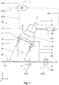
- a device 10 according to the invention serves for descaling a workpiece 12 which is moved in a direction of movement X relative to the device 10.
- the workpiece can be hot rolled material that is moved past the device 10.
- a feed rate at which the workpiece 12 is moved past the device 10 in the direction of movement X is shown in FIG Fig. 1 and in Fig. 2 each symbolized by the arrow "v".
- a device 10 according to the invention has a jet nozzle arrangement with a plurality of jet nozzles, from which a liquid, in particular water, is sprayed onto a surface of a workpiece under high pressure.
- the jet nozzle arrangement can consist of a rotor head ( Fig. 1 ) or from a spray bar ( Fig. 2 ) be formed, as explained in detail below.
- jet nozzles 16 are provided, from which a liquid 18 (in Fig. 1 simply symbolized with dashed lines) is sprayed under high pressure onto a surface 20 of the workpiece 12 in order to descaling the workpiece 12 in a suitable manner.
- a jet nozzle arrangement which, as just explained, is in the form of a rotor head 14 which can be rotated about an axis of rotation R.
- the rotor head 14 is rotated about its axis of rotation R by motor means (not shown), for example by an electric motor.
- the jet nozzles 16 are attached to an end face of the rotor head 14 which faces the workpiece 12.
- the jet nozzles 16 are in the embodiment of FIG Fig. 1 firmly attached to the rotor head 14.
- the longitudinal axes L of the jet nozzles 16 are aligned parallel to the axis of rotation R of the rotor head 14.
- the jet nozzles 16 are designed to be height-adjustable, for example by attaching them to a height-adjustable holder which is arranged in the Fig. 1 and Fig. 2 simplified symbolized by the double arrow "H".
- the holder H can have an actuator (not shown in the drawing).
- a distance A which an end face of the jet nozzles 16 has to the surface 20 of the workpiece 12, can thus be adjusted, if necessary, by actuating the actuator. In the sense of the present invention, this distance A is to be understood as the spraying distance. If this distance A is reduced, the resulting impact pressure of the liquid 18 on the surface 20 of the workpiece 12 increases.
- the device 10, such as for the embodiment of FIG Fig. 1 shown comprises a control device 22 and a high-pressure pump unit 24, which is connected to the control device 22 for signaling purposes.
- the rotor head 14 is connected to the high-pressure pump unit 24 via a connecting line in such a way that the jet nozzles 16 are in fluid communication with the high-pressure pump unit 24 and are therefore supplied with a liquid under high pressure by the high-pressure pump unit 24.
- the liquid 18, which is then sprayed under high pressure from the jet nozzles 16 onto the workpiece 12 it is preferably water, without any restriction being limited to the medium water.
- the high-pressure pump unit 24 is equipped with a frequency controller 25. This makes it possible, in particular, to control the high-pressure pump unit 24 in a stepless manner by means of the control device 22 in order to be able to change the pressure at which the liquid 18 is supplied to the jet nozzles 16 even in small steps. Further details for such a control of the high-pressure pump unit 24 are set out in detail below.
- the device 10 comprises a surface inspection device 26, which - in relation to the direction of movement X of the workpiece 12 - is arranged downstream of the rotor head 14 and close to it.
- the surface inspection device 26 can be based on a specialized optical measuring principle in which a 3D measurement is carried out for a surface 20 of the workpiece 12 and a height profile for the surface 20 of the workpiece 12 is derived from this. Alternatively, a spectral analysis is carried out on the surface 20 of the workpiece 12 by means of the surface inspection device 26.
- the surface inspection device 26 is also connected to the control device 22 in terms of signal technology.
- scale or residual scale can be detected on the surface 20 of the workpiece 12.
- the surface inspection device 26 is designed such that both an upper side and an underside of the workpiece 12 are monitored.
- the signaling connection between the control device 22 and the high-pressure pump unit 24 is shown in FIG Fig. 1 designated by reference numeral 23.1.
- the signal connection between the control device 22 and the surface inspection device 26 is designated by the reference symbol 23.2.
- the signaling connection between the control device 22 and the height adjustment H is designated by the reference symbol 23.3.
- the signal connection between the control device 22 and a device (not shown), by means of which the feed speed v of the workpiece 12 can be set or changed, is identified by the reference symbol 23.4.
- These connections 23.1, 23.2, 23.3 and 23.4 can either be physical lines or a suitable radio link or the like.
- the high-pressure pump unit 24 and the surface inspection device 26 apply to the embodiment of FIG Fig. 2 the same relationships as for the embodiment of Fig. 1 , these technical components for simplification in Fig. 2 are not shown.
- Fig. 3 shows a further embodiment of the device 10 according to the invention, namely in a simplified top view.
- two jet nozzle arrangements 14.1 and 14.2 are arranged one behind the other with respect to the direction of movement X of the workpiece 12.
- Each of these jet nozzle arrangements 14.1 and 14.2 is connected to the high pressure pump unit 24, as with reference to FIG Fig. 1 explained.
- the surface inspection device 26 is positioned downstream of the jet nozzle arrangement 14.2.
- a width of the workpiece 12 extends in the direction y, the axes of rotation R for the rotor heads 14.1 and 14.2 each running perpendicular to the plane of the drawing.
- the jet nozzle arrangement 14.1 is a pair of rotor heads 28 (cf. Fig. 4 ) can be, wherein the jet nozzle arrangement 14.2 arranged downstream thereof is a spray bar pair 38 (cf. Fig. 2 ) can act.
- the spray bar pair 38 also correspond to the jet nozzle arrangement 14.1, where then the pair of rotor heads 28 is arranged downstream thereof, namely at the location of the jet nozzle arrangement 14.2.
- the jet nozzle arrangements 14.1 and 14.2 in the embodiment of FIG Fig. 3 both either from a pair of rotor heads 28 ( Fig. 4 ), or each from a spray bar pair 38 ( Fig. 2 ) are formed.
- Fig. 4 shows a side view of a pair of rotor heads 28, in which a rotor head 14 is provided above and below the workpiece 12, ie both on its top and on its bottom. It can be seen that the rotor head 14, which is arranged below the workpiece 12, is positioned downstream of the rotor head 14, which is arranged above the workpiece 12, with respect to the direction of movement X of the workpiece 12. This is so that the liquid 18 which is sprayed out of the jet nozzles 16 of the rotor head 14 arranged below the workpiece 12 does not collide with the rotor head 14 arranged above the workpiece 12 if there is no workpiece 12 between these two rotor heads.
- Fig. 4 shows a side view of a pair of rotor heads 28, in which a rotor head 14 is provided above and below the workpiece 12, ie both on its top and on its bottom. It can be seen that the rotor head 14, which is arranged below the workpiece 12, is positioned downstream of the rotor head 14, which
- Fig. 4 it is additionally pointed out that this can also be a side view of a pair of rotor modules in which a plurality of rotor heads 14 (cf. Fig. 1 ) are combined in the y direction to form a rotor module above and below a workpiece 12.
- the individual jet nozzles 16 are connected to a common pressurized water line D, which is connected to the high-pressure pump unit 24. This ensures that the jet nozzles 16 are supplied with high-pressure water.
- Fig. 2 shows a simplified side view of a device 10 according to the invention according to a further embodiment.
- a jet nozzle arrangement of the device 10 is designed in the manner of a so-called spray bar 36, the longitudinal extension of which is transverse (ie in Fig. 2 in the direction of the y-axis) to the direction of movement X of the workpiece 12.
- the longitudinal extent of a spray bar 36 generally corresponds to a width of the workpiece 12 to be descaled.
- a plurality of jet nozzles 16 are arranged, of which only the jet nozzle 16 lying at the front is shown in the illustration in FIG. 7.
- a spray bar 36 is provided above and below the workpiece 12, which thus form a spray bar pair 38.
- the jet nozzles 16 of the spray bar pair are arranged on the spray bars 36 at an angle with respect to an orthogonal to the surface 20 of the workpiece 12 such that the liquid 18 which is sprayed out of the jet nozzles 16 has an angle ⁇ on the surface 20 of the workpiece 12 strikes.
- a separate surface scanning unit 40 ( Fig. 3 ) may be provided, which is arranged upstream of a jet nozzle arrangement 14 and is connected to the control device 22 in terms of signal technology.
- a surface scanning unit 40 functions electronically and comprises an optical measuring system that can work according to the laser beam principle. If an irregularity should occur on the surface, this is detected by the surface scanning unit 40 and a corresponding one Signal generated, on the basis of which the control device 22 then the actuator of the height-adjustable bracket H (see. Fig. 1 , Fig. 2 ) controls to immediately increase the distance A of the jet nozzle arrangement to the surface of the workpiece 12. This ensures that the jet nozzle arrangement is not damaged if the workpiece 12 should have such an irregularity.
- the workpiece 12 is moved past the device 10, namely at a feed rate which is symbolized in the respective figures with "v".
- a specific energy input E or "spray energy"
- the impact pressure with which the liquid 18 impinges on the surface 20 of the workpiece 12 is dependent both on the pressure and the volume with which the liquid is sprayed out of the jet nozzles 16 and on the distance the jet nozzles 16 from the surface 20 of the workpiece.
- V ⁇ spec V ⁇ b
- the invention now works as follows: For a desired descaling of the surfaces 20 of the workpiece 12, it is moved in the direction of movement X relative to the device 10 according to the invention.
- the liquid 18 is sprayed from the jet nozzles 16 under high pressure onto the surfaces 20 of the workpiece 12, namely both on its upper side and on its lower side.
- the specific energy input E can be increased, for example, by increasing the pressure with which the liquid is supplied to the jet nozzles and / or the volume flow V, and / or by increasing the distance A of the jet nozzles to the surface 20 of the workpiece 12 and / or the feed speed v are reduced, and / or by connecting a further jet nozzle arrangement.
- a reduction in the specific energy input E is achieved by the pressure at which the liquid is supplied to the jet nozzles and / or the volume flow V is reduced, and / or by increasing the distance A of the jet nozzles to the surface 20 of the workpiece and / or the feed speed v, and / or by adding another Jet nozzle arrangement is switched off.
- an increase in the specific energy input E takes place e.g. in the event that it is determined on the basis of the signals from the surface inspection device 26 by means of the control device 22 that the surface quality of the workpiece 12 falls below a predetermined target value. Conversely, this means that the specific energy input E is reduced as long as the surface quality of the workpiece 12 maintains a predetermined target value.
- Fig. 5 shows a flowchart to illustrate an operating mode of the device 10 according to the invention or an implementation of a method according to the invention.
- the descaling quality is continuously monitored by means of the surface inspection device 26.
- This allows local and immediately adjacent to a jet nozzle arrangement, for. B. in the form of a pair of rotor modules or a spray bar 38, it can be determined whether the desired surface quality for the workpiece 12 reaches a predetermined target value. If this is not the case, suitable control of the high-pressure pump unit 24 or of the / the frequency controller / s 25 provided for this purpose, the pressure with which the liquid 18 is supplied to the jet nozzles 16 can be increased by means of the control device 22, with a further pump of the high-pressure pump unit 24 possibly also being switched on.
- the operating parameters of the device 10 can also be adapted: by suitably actuating the high-pressure pump unit 24 by means of the control device 22, the pressure at which the liquid 18 is supplied to the jet nozzles 16 can be reduced until a recognizable residual scale falls below a minimal impact displays and then this pressure must be increased slightly again.
- the pressure for the jet nozzles 16 supplied liquid 18 is set to a sufficiently large value with which the surface quality reaches the predetermined target value.
- the impact pressure or the descaling pressure can be changed by adjusting the height of a jet nozzle arrangement.
- This height adjustment is in the Fig. 1 and in the Fig. 2 each symbolized by the arrow "H", and is achieved by the control device 22 suitably actuating the actuator of the height-adjustable holder H to which the jet nozzle arrangement is attached.
- the feed speed v of the workpiece 12 can be adapted to change the specific energy input E.
- the flow chart according to Fig. 5 illustrates a control loop in order to determine or set the desired specific energy input E with which the workpiece 12 is descaled.
- the abovementioned options are carried out or applied until the surface quality for the workpiece reaches a predetermined target value (in Fig. 5 referred to as the "target result").
Landscapes
- Engineering & Computer Science (AREA)
- Mechanical Engineering (AREA)
- Nozzles (AREA)
- Cleaning By Liquid Or Steam (AREA)
- Cleaning In General (AREA)
- Spray Control Apparatus (AREA)
- Application Of Or Painting With Fluid Materials (AREA)
Claims (15)
- Dispositif (10) destiné au décalaminage d'une pièce à usiner (12), de préférence d'un produit de laminage à chaud, qui se déplace par rapport au dispositif (10) dans une direction de déplacement (X), comprenant :au moins un premier agencement de buses d'éjection (14 ; 28 ; 36 ; 38) comprenant un certain nombre de buses d'éjection (16) à partir desquelles un liquide (18), en particulier de l'eau, peut être évacué sous haute pression sur une surface (20) de la pièce à usiner (12) ;un mécanisme de commande (22) ; et
un mécanisme d'inspection de la surface (26) relié par l'intermédiaire de signaux (23.2) au mécanisme de commande (22), qui est disposé, par rapport à la direction de déplacement (X) de la pièce à usiner (12) en aval de l'agencement de buses d'éjection (14 ; 28 ; 36 ; 38) ; dans lequel, au moyen du mécanisme d'inspection de la surface (26), on peut détecter la présence de calamine sur la surface (20) de la pièce à usiner (12); dans lequel le mécanisme d'inspection de la surface est disposé en position directement limitrophe par rapport à l'agencement de buses d'éjection ;caractériséen ce que le mécanisme de commande (22) est conçu du point de vue de la technique de programmation d'une manière telle que l'apport d'énergie spécifique, avec lequel une surface (22) de la pièce à usiner est sollicitée par l'intermédiaire du liquide (18) évacué à partir des buses d'éjection (16), peut être réglé au moyen du mécanisme de commande (22) en fonction des signaux du mécanisme d'inspection de la surface (26), eten ce que le mécanisme de commande (22) est conçu du point de vue de la technique de programmation d'une manière telle que, sur la base des signaux du mécanisme d'inspection de la surface (26), on détermine une qualité de la surface pour la pièce à usiner (12) et on la compare à une valeur de consigne prédéterminée ; dans lequel le réglage de l'apport d'énergie spécifique a lieu d'une manière telle que l'on augmente l'apport en question au cas où la qualité de la surface de la pièce à usiner dépasse vers le bas la valeur de consigne prédéfinie et d'une manière telle qu'on le diminue au cas où la qualité de la surface de la pièce à usiner dépasse vers le haut la valeur de consigne prédéterminée. - Dispositif (10) selon la revendication 1, caractérisé en ce que l'on prévoit une unité de pompage sous haute pression (24) reliée par l'intermédiaire de signaux (23.1) au mécanisme de commande (22), qui est mise en liaison par fluide avec les buses d'éjection (16) de l'agencement de buses d'éjection (14 ; 28 ; 36 ; 38) ; dans lequel l'unité de pompage sous haute pression (24) peut être réglée au moyen du mécanisme de commande (22), d'une manière telle que la pression, avec laquelle le liquide (18) est acheminé aux buses d'éjection (16), peut être modifiée ; de préférence, d'une manière telle que la pression destinée au liquide (18) acheminé aux buses d'éjection, au cas où la qualité de la surface de la pièce à usiner (12) dépasse vers le haut ou dépasse vers le bas la valeur de consigne prédéterminée, est soumise de manière correspondante à une diminution ou à une augmentation.
- Dispositif (10) selon la revendication 2, caractérisé en ce que l'unité de pompage sous haute pression (24) est équipée d'un régulateur de fréquence (25) ; dans lequel l'unité de pompage sous haute pression (24) est excitée en fonction des signaux du mécanisme d'inspection de la surface (26) afin de diminuer ou d'augmenter de manière correspondante la pression destinée au liquide (18) acheminé aux buses d'éjection.
- Dispositif (10) selon l'une quelconque des revendications précédentes, caractérisé en ce qu'une distance (A) entre l'agencement de buses d'éjection (14 ; 28 ; 36 ; 38) et la surface (20) de la pièce à usiner (12) peut être modifiée ; dans lequel cette distance (A) peut être commandée, de préférence peut être réglée au moyen du mécanisme de commande (22).
- Dispositif (10) selon l'une quelconque des revendications précédentes, caractérisé en ce que l'on peut établir une vitesse d'avance (v) de la pièce à usiner (12) d'une manière réglée au moyen du mécanisme de commande (22).
- Dispositif (10) selon l'une quelconque des revendications précédentes, caractérisé en ce que le mécanisme d'inspection de la surface (26) est conçu d'une manière telle que l'on procède de cette manière à une mesure en trois dimensions d'une surface (20) de la pièce à usiner (12) et que l'on déduit à partir de cette mesure un profil de hauteur pour la surface (20) de la pièce à usiner (12).
- Dispositif (10) selon l'une quelconque des revendications précédentes, caractérisé en ce que l'on prévoit un deuxième agencement de buses d'éjection (14.2), qui comprend un certain nombre de buses d'éjection (16), qui est disposé en position limitrophe par rapport au premier agencement de buses d'éjection (14.1) et, par rapport à une direction de déplacement (X) de la pièce à usiner, en amont ou en aval de cette dernière, et qui est relié au mécanisme de commande (22) par l'intermédiaire de signaux ; dans lequel, au cas où la qualité de la surface de la pièce à usiner (12) dépasse vers le bas la valeur de consigne prédéterminée, le deuxième agencement de buses d'éjection (14.2) peut être mis en circuit de manière complémentaire au premier agencement de buses d'éjection (14.1), si bien que, de cette manière, à partir des buses d'éjection (16) du deuxième agencement de buses d'éjection (14.2) mis en circuit, du liquide (18) sous haute pression peut être évacué sur une surface (20) de la pièce à usiner (12).
- Dispositif (10) selon l'une quelconque des revendications précédentes, caractérisé en ce que l'on prévoit une unité de balayage de la surface (40) reliée au mécanisme de commande (22) par l'intermédiaire de signaux (23.3), qui est disposée, par rapport à la direction de déplacement (X) de la pièce à usiner (12) en amont de l'agencement de buses d'éjection (14 ; 28 ; 36 ; 38) ; dans lequel le mécanisme de commande (22) est relié par l'intermédiaire de signaux à un actionneur d'un mécanisme de support (H) de l'agencement de buses d'éjection (14 ; 28 ; 36 ; 38), réglable en hauteur, d'une manière telle que, au cas où l'on constate au moyen de l'unité de balayage de la surface (40) une irrégularité sur une surface (20) de la pièce à usiner (12), le mécanisme de commande (22) excite l'actionneur du mécanisme de support (H) réglable en hauteur, de telle manière que la distance (A) de l'agencement de buses d'éjection (14 ; 28 ; 36 ; 38) par rapport à la pièce à usiner (12) peut être augmentée.
- Procédé destiné au décalaminage d'une pièce à usiner (12), de préférence d'un produit de laminage à chaud, qui se déplace par rapport à un premier agencement de buses d'éjection (14 ; 28 ; 36 ; 38), qui présente un certain nombre de buses d'éjection (16), dans une direction de déplacement (X) ; dans lequel, pour le décalaminage de la pièce à usiner (12) on projette un liquide (18), en particulier de l'eau, à partir des buses d'éjection (16) sous haute pression sur une surface (20) de la pièce à usiner (12) ; dans lequel un mécanisme de commande (22) est relié à l'agencement de buses d'éjection (14 ; 28 ; 36 ; 38) et à un mécanisme d'inspection de la surface (26), respectivement par l'intermédiaire de signaux (23.1 ; 23.2 ; 23.3 ; 23.4) ; dans lequel, au moyen du mécanisme d'inspection de la surface (26), on examine une surface (20) de la pièce à usiner (12) en aval de l'agencement de buses d'éjection (14 ; 28 ; 36 ; 38) par rapport à la direction de déplacement (X) de la pièce à usiner (12) ; dans lequel, au moyen du mécanisme d'inspection de la surface, on examine une surface de la pièce à usiner en position directement adjacente à l'agencement de buses d'éjection ;
caractérisé
en ce que l'apport d'énergie spécifique, avec lequel une surface (20) de la pièce à usiner est sollicitée par l'intermédiaire du liquide (18) évacué à partir des buses d'éjection (16), est réglé au moyen du mécanisme de commande (22) en fonction des signaux du mécanisme d'inspection de la surface (26), et
en ce que, sur la base des signaux du mécanisme d'inspection de la surface (26), on détermine une qualité de la surface pour la pièce à usiner (12) et on la compare à une valeur de consigne prédéterminée ; dans lequel on règle l'apport d'énergie spécifique d'une manière telle qu'on augmente l'apport en question au cas où la qualité de la surface de la pièce à usiner dépasse vers le bas la valeur de consigne prédéfinie et d'une manière telle qu'on le diminue au cas où la qualité de la surface de la pièce à usiner dépasse vers le haut la valeur de consigne prédéterminée. - Procédé selon la revendication 9, caractérisé en ce que, au moyen du mécanisme de commande (22) on règle une unité de pompage sous haute pression (24) dans le but de modifier la pression avec laquelle le liquide (18) est acheminé aux buses d'éjection (16).
- Procédé selon la revendication 10, caractérisé en ce que l'on augmente la pression destinée au liquide (18) acheminé aux buses d'éjection (16) au cas où la qualité de la surface de la pièce à usiner (12) dépasse vers le bas la valeur de consigne prédéterminée ou bien on diminue la pression destinée au liquide (18) acheminé aux buses d'éjection (16) jusqu'à ce que la qualité de la surface de la pièce à usiner (12) respecte la valeur de consigne prédéterminée.
- Procédé selon l'une quelconque des revendications 9 à 11, caractérisé en ce que, au moyen du mécanisme de commande (22) on modifie de manière réglée une distance (A) que présente l'agencement de buses d'éjection (14 ; 28 ; 36 ; 38) par rapport à une surface (20) de la pièce à usiner (12) ; dans lequel on diminue la distance (A) de l'agencement de buses d'éjection (14 ; 28 ; 36 ; 38) par rapport à la surface de la pièce à usiner (12) au cas où la qualité de la surface de la pièce à usiner (12) dépasse vers le bas la valeur de consigne prédéterminée ou bien dans lequel on augmente la distance (A) de l'agencement de buses d'éjection (14 ; 28 ; 36 ; 38) par rapport à la surface (20) de la pièce à usiner (12) jusqu'à ce que la qualité de la surface de la pièce à usiner (12) respecte la valeur de consigne prédéterminée.
- Procédé selon l'une quelconque des revendications 9 à 12, caractérisé en ce que l'on diminue une vitesse d'avance (v) de la pièce à usiner (12) dans sa direction de déplacement (X) au cas où la qualité de la surface de la pièce à usiner (12) dépasse vers le bas la valeur de consigne prédéterminée ou bien en ce que l'on augmente une vitesse d'avance (v) de la pièce à usiner dans sa direction de déplacement (X) jusqu'à ce que la qualité de la surface de la pièce à usiner (12) respecte la valeur de consigne prédéterminée.
- Procédé selon l'une quelconque des revendications 9 à 13, caractérisé en ce que le mécanisme d'inspection de la surface (26) est disposé, par rapport à la direction de déplacement (X) de la pièce à usiner (12), en aval de l'agencement de buses d'éjection (14 ; 28 ; 36 ; 38) et en position directement adjacente à l'agencement en question.
- Procédé selon l'une quelconque des revendications 9 à 14, caractérisé en ce que l'on prévoit un deuxième agencement de buses d'éjection (14.2) qui est disposé en position limitrophe par rapport au premier agencement de buses d'éjection (14.1) et, par rapport à une direction de déplacement (X) de la pièce à usiner, en amont ou en aval de cette dernière, et qui est relié au mécanisme de commande (22) par l'intermédiaire de signaux ; dans lequel, au cas où la qualité de la surface de la pièce à usiner (12) dépasse vers le bas la valeur de consigne prédéterminée, le deuxième agencement de buses d'éjection (14.2) est mis en circuit de manière complémentaire au premier agencement de buses d'éjection (14.1), si bien que, de cette manière, à partir des buses d'éjection (16) du deuxième agencement de buses d'éjection (14.2) mis en circuit, du liquide (18) sous haute pression peut être projeté sur une surface (20) de la pièce à usiner (12).
Applications Claiming Priority (6)
| Application Number | Priority Date | Filing Date | Title |
|---|---|---|---|
| DE102016204570 | 2016-03-18 | ||
| DE102016204579 | 2016-03-18 | ||
| DE102016217562.9A DE102016217562A1 (de) | 2016-03-18 | 2016-09-14 | Vorrichtung und Verfahren zum Entzundern eines bewegten Werkstücks |
| DE102016217560.2A DE102016217560A1 (de) | 2016-03-18 | 2016-09-14 | Vorrichtung und Verfahren zum Entzundern eines Werkstücks |
| DE102016217561.0A DE102016217561A1 (de) | 2016-03-18 | 2016-09-14 | Vorrichtung und Verfahren zum Entzundern eines bewegten Werkstücks |
| PCT/EP2017/056141 WO2017158035A1 (fr) | 2016-03-18 | 2017-03-15 | Dispositif et procédé de décalaminage d'une pièce |
Publications (2)
| Publication Number | Publication Date |
|---|---|
| EP3429771A1 EP3429771A1 (fr) | 2019-01-23 |
| EP3429771B1 true EP3429771B1 (fr) | 2020-07-08 |
Family
ID=59751469
Family Applications (3)
| Application Number | Title | Priority Date | Filing Date |
|---|---|---|---|
| EP17710888.3A Active EP3429770B1 (fr) | 2016-03-18 | 2017-03-14 | Dispositif et procédé de décalaminage d'une pièce mobile |
| EP17711626.6A Active EP3429771B1 (fr) | 2016-03-18 | 2017-03-15 | Dispositif et procédé de décalaminage d'une pièce |
| EP17712093.8A Active EP3429773B1 (fr) | 2016-03-18 | 2017-03-17 | Dispositif et procédé de décalaminage d'une pièce déplacée |
Family Applications Before (1)
| Application Number | Title | Priority Date | Filing Date |
|---|---|---|---|
| EP17710888.3A Active EP3429770B1 (fr) | 2016-03-18 | 2017-03-14 | Dispositif et procédé de décalaminage d'une pièce mobile |
Family Applications After (1)
| Application Number | Title | Priority Date | Filing Date |
|---|---|---|---|
| EP17712093.8A Active EP3429773B1 (fr) | 2016-03-18 | 2017-03-17 | Dispositif et procédé de décalaminage d'une pièce déplacée |
Country Status (8)
| Country | Link |
|---|---|
| US (1) | US11103907B2 (fr) |
| EP (3) | EP3429770B1 (fr) |
| JP (3) | JP6770088B2 (fr) |
| KR (3) | KR102183495B1 (fr) |
| CN (3) | CN108778543B (fr) |
| DE (3) | DE102016217560A1 (fr) |
| RU (3) | RU2697746C1 (fr) |
| WO (3) | WO2017157940A1 (fr) |
Families Citing this family (19)
| Publication number | Priority date | Publication date | Assignee | Title |
|---|---|---|---|---|
| DE102017122802B3 (de) * | 2017-09-29 | 2018-10-25 | Hauhinco Maschinenfabrik G. Hausherr, Jochums Gmbh & Co. Kg | Entzunderungsvorrichtung |
| AU2018437298A1 (en) * | 2018-08-21 | 2021-03-18 | Hermetik Hydraulik Ab | A device and method for descaling rolling stock |
| DE102018215492A1 (de) * | 2018-09-12 | 2020-03-12 | Sms Group Gmbh | Verfahren zu Herstellung eines metallischen Gutes |
| DE102019200760A1 (de) | 2019-01-22 | 2020-07-23 | Sms Group Gmbh | Vorrichtung und Verfahren zum Entzundern eines bewegten Werkstücks |
| CN110026308A (zh) * | 2019-05-24 | 2019-07-19 | 沈阳中泽智能装备有限公司 | 一种应用于喷涂领域的喷吸一体化装置 |
| KR102323789B1 (ko) * | 2019-08-19 | 2021-11-10 | 주식회사 포스코 | 이물 제거장치 |
| CN110774178B (zh) * | 2019-10-30 | 2024-09-17 | 北京电子科技职业学院 | 一种无酸除鳞丸料流的保护与引导装置 |
| CA3159129A1 (fr) | 2019-12-13 | 2021-06-17 | Ram BALACHANDAR | Systemes de refroidissement par contact par jet et pulverisation assistes par dissipateur poreux |
| CN112139107B (zh) * | 2020-07-30 | 2023-10-31 | 福涞堡造纸技术(上海)有限公司 | 一种丝网清洗干燥装置 |
| CN113042444B (zh) * | 2021-04-07 | 2023-03-17 | 重庆大学 | 一种锻件高压水除鳞装置的喷淋组件 |
| CN113000752B (zh) * | 2021-04-08 | 2022-11-08 | 重庆大学 | 一种锻件高压水除鳞装置及方法 |
| CN113500032A (zh) * | 2021-05-26 | 2021-10-15 | 张宝玉 | 一种高端轨道用的智能自清洗装置 |
| CN113522584B (zh) * | 2021-06-17 | 2022-10-04 | 广州泽亨实业有限公司 | 一种喷涂系统 |
| KR102529203B1 (ko) * | 2021-07-27 | 2023-05-08 | 현대제철 주식회사 | 열연 강판의 균일 냉각 장치 |
| EP4140643A1 (fr) * | 2021-08-31 | 2023-03-01 | Karl Heesemann Maschinenfabrik GmbH & Co. KG | Dispositif de dépoussiérage, machine à poncer et procédé de dépoussiérage d'une pièce |
| CN113731913A (zh) * | 2021-09-07 | 2021-12-03 | 鹏知创科技(深圳)有限公司 | 一种三维高压水射流清洗方法 |
| CN113814085A (zh) * | 2021-09-22 | 2021-12-21 | 江西省中子能源有限公司 | 一种扫粉除尘机用安全罩喷塑装置 |
| CN114192928B (zh) * | 2021-12-17 | 2023-05-02 | 张家港宏昌钢板有限公司 | 一种连铸坯切割瘤清理装置 |
| CN115194109A (zh) * | 2022-08-04 | 2022-10-18 | 河北新金钢铁有限公司 | 一种提高铸坯表面质量的设备及其使用方法 |
Family Cites Families (65)
| Publication number | Priority date | Publication date | Assignee | Title |
|---|---|---|---|---|
| US3510065A (en) * | 1968-01-05 | 1970-05-05 | Steinen Mfg Co Wm | Descaling nozzle |
| DE2843269C3 (de) * | 1978-10-04 | 1981-11-12 | Stahlwerke Peine-Salzgitter Ag, 3150 Peine | Verfahren und Vorrichtung zur Steuerung von Flämmaschinen zum Abflämmen von Oberflächen, insbesondere von Brammen |
| SU982838A1 (ru) * | 1980-05-29 | 1982-12-23 | за вители S iXOiOSIfA . , , т J «i-i- ittjи К.И. Хамидулов 5-J ..-,.,„., :Х- й1-гг;/д | Способ очистки поверхности полосы от печной окалины |
| JPS59215208A (ja) * | 1983-05-19 | 1984-12-05 | Kawasaki Steel Corp | 厚鋼板のスケ−ル模様防止方法 |
| JPS60169581A (ja) * | 1984-02-13 | 1985-09-03 | Nippon Steel Corp | 鋼ストリツプの残スケ−ル状態判別方法 |
| JPS60179637A (ja) * | 1984-02-28 | 1985-09-13 | Kawasaki Steel Corp | 熱間金属材料の表面欠陥検出方法 |
| DE3600144A1 (de) * | 1986-01-07 | 1987-07-09 | Schloemann Siemag Ag | Anordnung zum entfernen von zunder von warmgewalzten stahlbaendern |
| JPS62224417A (ja) * | 1986-03-25 | 1987-10-02 | Sumitomo Metal Ind Ltd | 熱延鋼板の脱スケ−ル方法 |
| JPH01205810A (ja) * | 1988-02-12 | 1989-08-18 | Sumitomo Metal Ind Ltd | デスケーリング後のスケール生成防止方法 |
| SU1533799A1 (ru) * | 1988-06-13 | 1990-01-07 | Донецкий политехнический институт | Устройство дл гидросбива окалины с нагретых заготовок |
| US4918959A (en) * | 1989-02-06 | 1990-04-24 | Petrolite Corporation | Method for preventing the buildup of oily deposits on rolling mill scale |
| JPH04182020A (ja) * | 1990-11-14 | 1992-06-29 | Mitsubishi Heavy Ind Ltd | ステンレス鋼板の脱スケール方法 |
| ES2108170T3 (es) * | 1992-07-31 | 1997-12-16 | Danieli Off Mecc | Dispositivo de descascarillado que emplea agua. |
| DE4328303C2 (de) * | 1992-12-23 | 1997-02-13 | Juergen Gaydoul | Einrichtung zum Entzundern von warmem Walzgut |
| DE4345351B4 (de) * | 1993-01-28 | 2004-08-12 | Sms Demag Ag | Zunderwäscher |
| JP3603841B2 (ja) * | 1993-05-06 | 2004-12-22 | Jfeスチール株式会社 | デスケーリング装置 |
| KR950007989Y1 (ko) * | 1993-07-27 | 1995-09-27 | 포항종합제철 주식회사 | 열간압연강판의 스케일 제거장치 |
| US5697241A (en) * | 1993-08-23 | 1997-12-16 | Voest-Alpine Industrieanlagenbau Gmbh | Rolling arrangement |
| JP3307771B2 (ja) * | 1993-08-23 | 2002-07-24 | ハンス‐ユルゲン、ガイドール | 熱間圧延鋼板のデスケーリング手段 |
| JPH08332514A (ja) * | 1995-06-09 | 1996-12-17 | Nippon Steel Corp | 薄スケール鋼板の連続熱間圧延設備及び薄スケール鋼板の製造方法 |
| DE19535789C2 (de) * | 1995-09-26 | 1997-09-11 | Hermetik Hydraulik Ab | Einrichtung zum Entzundern von Halbzeugen |
| AT406234B (de) | 1996-02-02 | 2000-03-27 | Voest Alpine Ind Anlagen | Verfahren zum entzundern eines werkstückes |
| JPH10282029A (ja) | 1997-04-08 | 1998-10-23 | Matsushita Electric Ind Co Ltd | 湿度検出器 |
| JPH11156426A (ja) * | 1997-11-25 | 1999-06-15 | Hitachi Ltd | デスケーリング装置及びデスケーリング方法 |
| JP3963408B2 (ja) * | 1997-11-28 | 2007-08-22 | 東海カーボン株式会社 | 熱延鋼板のスケール検知方法および装置 |
| DE19802425A1 (de) * | 1998-01-23 | 1999-07-29 | Schloemann Siemag Ag | Vorrichtung zum Entzundern von Walzgut |
| JPH11216513A (ja) | 1998-01-28 | 1999-08-10 | Nkk Corp | 鋼材のデスケーリング装置 |
| DE19817002A1 (de) * | 1998-04-17 | 1999-10-21 | Schloemann Siemag Ag | Einrichtung zum Entzundern von Halbzeugen |
| JPH11347622A (ja) * | 1998-06-03 | 1999-12-21 | Kawasaki Steel Corp | デスケーリング装置および方法 |
| KR200296389Y1 (ko) * | 1998-11-24 | 2003-02-19 | 주식회사 포스코 | 좌우이동형 디스케일링장치_ |
| RU2165812C1 (ru) * | 1999-08-05 | 2001-04-27 | Открытое акционерное общество Верхнесалдинское металлургическое производственное объединение | Установка для обработки поверхности плоских полуфабрикатов |
| JP2001047122A (ja) * | 1999-08-12 | 2001-02-20 | Hitachi Ltd | デスケーリング方法及びデスケーリング装置 |
| JP2001300627A (ja) * | 2000-04-18 | 2001-10-30 | Nippon Steel Corp | 厚鋼板冷却方法 |
| DE10031978A1 (de) * | 2000-06-30 | 2002-01-10 | Sms Demag Ag | Verfahren und Vorrichtung zur automatischen Zundererkennung aus Oberflächen von metallischem Bandgut, insbesondere von warmgewalztem Stahlband und Edelstahlband |
| DE10110324A1 (de) * | 2001-03-03 | 2002-09-05 | Sms Demag Ag | Verfahren zum Entzundern von Bändern |
| KR100838722B1 (ko) * | 2001-12-05 | 2008-06-16 | 주식회사 포스코 | 열간압연공정에서의 스트립표면 결함부 검색장치 |
| DE10252178A1 (de) * | 2002-11-09 | 2004-05-27 | Sms Demag Ag | Verfahren und Vorrichtung zum Entzundern und/oder Reinigen eines Metallstrangs |
| KR100962952B1 (ko) * | 2002-12-27 | 2010-06-10 | 주식회사 포스코 | 페라이트계 스테인레스강의 소둔 및 연속탈스케일 방법 |
| JP4050201B2 (ja) * | 2003-07-14 | 2008-02-20 | 株式会社神戸製鋼所 | 圧延材の冷却装置の制御方法 |
| DE10332693A1 (de) * | 2003-07-18 | 2005-02-10 | Sms Demag Ag | Verfahren und Vorrichtung zum Entzundern und/oder reinigen eines Metallstranges |
| MXPA06009715A (es) | 2004-02-27 | 2007-03-26 | Hermetik Hydraulik Ab | Dispositivo hidraulico que se usa para descascarillar productos laminados calientes. |
| JP2006346713A (ja) * | 2005-06-17 | 2006-12-28 | Jfe Steel Kk | 表面検査室を設けた厚板圧延ライン |
| AT504782B1 (de) | 2005-11-09 | 2008-08-15 | Siemens Vai Metals Tech Gmbh | Verfahren zur herstellung eines warmgewalzten stahlbandes und kombinierte giess- und walzanlage zur durchführung des verfahrens |
| DE102006004688A1 (de) | 2006-02-02 | 2007-08-16 | Sms Demag Ag | Verfahren und Giess-Walz-Anlage zum Herstellen von warmgewalztem Metall - insbesondere Stahlwerkstoff-Band mit hoher Oberflächengüte |
| AT507663B1 (de) * | 2009-04-09 | 2010-07-15 | Siemens Vai Metals Tech Gmbh | Verfahren und vorrichtung zum aufbereiten von warmwalzgut |
| JP5672664B2 (ja) * | 2009-05-18 | 2015-02-18 | Jfeスチール株式会社 | 鋼板のデスケーリング方法およびその装置 |
| CN201516448U (zh) * | 2009-11-02 | 2010-06-30 | 一重集团大连设计研究院有限公司 | 新型精轧高压水除鳞机 |
| JP5423575B2 (ja) * | 2010-05-10 | 2014-02-19 | 新日鐵住金株式会社 | 鋼板の冷却装置 |
| RU103313U1 (ru) * | 2010-08-27 | 2011-04-10 | Виктор Павлович Комиссаров | Устройство для гидросбива окалины с обрабатываемой трубы перед прокатным станом |
| JP5646261B2 (ja) * | 2010-09-22 | 2014-12-24 | 三菱日立製鉄機械株式会社 | 熱延鋼帯の冷却装置 |
| TWI511809B (zh) * | 2011-02-25 | 2015-12-11 | China Steel Corp | Method and apparatus for deruring hot - rolled high - pressure fluid |
| ITUD20110101A1 (it) * | 2011-06-30 | 2012-12-31 | Danieli Off Mecc | Dispositivo e procedimento di rimozione della scaglia da un prodotto metallico |
| JP5906712B2 (ja) * | 2011-12-15 | 2016-04-20 | Jfeスチール株式会社 | 熱鋼板のデスケーリング設備およびデスケーリング方法 |
| JP5790528B2 (ja) * | 2012-02-09 | 2015-10-07 | 東芝三菱電機産業システム株式会社 | 圧延デスケーリング装置の制御装置 |
| CN103418624B (zh) * | 2012-05-25 | 2016-01-27 | 宝山钢铁股份有限公司 | 一种冷态金属板带连续射流除鳞工艺 |
| CN102716922B (zh) * | 2012-06-28 | 2015-04-01 | 宝山钢铁股份有限公司 | 一种大直径金属棒材表面射流除鳞系统及方法 |
| DE102012214298A1 (de) * | 2012-08-10 | 2014-02-13 | Sms Siemag Ag | Verfahren zur Reinigung und/oder Entzunderung einer Bramme oder eines Vorbandes mittels eines Zunderwäschers und Zunderwäscher |
| KR101443097B1 (ko) | 2013-03-28 | 2014-09-22 | 현대제철 주식회사 | 열연강판의 스케일 흠 검출장치 및 그 제어방법 |
| GB2514599B (en) * | 2013-05-30 | 2015-07-08 | Siemens Vai Metals Tech Gmbh | Adjustable descaler |
| DE102013224506A1 (de) * | 2013-11-29 | 2015-06-03 | Sms Siemag Ag | Verfahren und Vorrichtung zum Entzundern einer metallischen Oberfläche sowie Anlage zum Herstellen von metallischen Halbzeugen |
| CN104001728A (zh) * | 2014-06-12 | 2014-08-27 | 鞍钢股份有限公司 | 一种除磷箱风动挡水板的控制方法 |
| DE102014109160B4 (de) | 2014-06-30 | 2020-04-23 | Hammelmann Maschinenfabrik Gmbh | Vorrichtung und Verfahren zum Reinigen eines Körpers mit einer abzutragenden Oberflächenschicht |
| WO2016151825A1 (fr) * | 2015-03-25 | 2016-09-29 | 株式会社神戸製鋼所 | Procédé et dispositif de décalaminage d'un fil métallique |
| CN204819092U (zh) * | 2015-07-28 | 2015-12-02 | 苏州翔楼金属制品有限公司 | 可在线操控的自动精准带钢除锈装置 |
| CN105081985B (zh) * | 2015-08-19 | 2018-07-10 | 秦皇岛树诚科技有限公司 | 一种钢带机械除鳞设备 |
-
2016
- 2016-09-14 DE DE102016217560.2A patent/DE102016217560A1/de not_active Withdrawn
- 2016-09-14 DE DE102016217561.0A patent/DE102016217561A1/de not_active Withdrawn
- 2016-09-14 DE DE102016217562.9A patent/DE102016217562A1/de not_active Withdrawn
-
2017
- 2017-03-14 RU RU2018131161A patent/RU2697746C1/ru active
- 2017-03-14 CN CN201780017801.0A patent/CN108778543B/zh active Active
- 2017-03-14 JP JP2018548685A patent/JP6770088B2/ja active Active
- 2017-03-14 EP EP17710888.3A patent/EP3429770B1/fr active Active
- 2017-03-14 US US16/085,013 patent/US11103907B2/en active Active
- 2017-03-14 KR KR1020187026798A patent/KR102183495B1/ko active IP Right Grant
- 2017-03-14 WO PCT/EP2017/055996 patent/WO2017157940A1/fr active Application Filing
- 2017-03-15 EP EP17711626.6A patent/EP3429771B1/fr active Active
- 2017-03-15 KR KR1020187027508A patent/KR102141440B1/ko active IP Right Grant
- 2017-03-15 CN CN201780018324.XA patent/CN108883452B/zh not_active Expired - Fee Related
- 2017-03-15 JP JP2018548822A patent/JP2019508257A/ja active Pending
- 2017-03-15 RU RU2018131172A patent/RU2701586C1/ru active
- 2017-03-15 WO PCT/EP2017/056141 patent/WO2017158035A1/fr active Application Filing
- 2017-03-17 CN CN201780018043.4A patent/CN108778544B/zh not_active Expired - Fee Related
- 2017-03-17 RU RU2018131260A patent/RU2699426C1/ru active
- 2017-03-17 WO PCT/EP2017/056462 patent/WO2017158191A1/fr active Application Filing
- 2017-03-17 JP JP2018548803A patent/JP7018020B2/ja active Active
- 2017-03-17 EP EP17712093.8A patent/EP3429773B1/fr active Active
- 2017-03-17 KR KR1020187027829A patent/KR102166086B1/ko active IP Right Grant
Non-Patent Citations (1)
| Title |
|---|
| None * |
Also Published As
Similar Documents
| Publication | Publication Date | Title |
|---|---|---|
| EP3429771B1 (fr) | Dispositif et procédé de décalaminage d'une pièce | |
| EP2188072B1 (fr) | Procédé et dispositif de nettoyage de la surface d'enveloppe d'un cylindre ou d'un rouleau | |
| DE102006051556A1 (de) | Verfahren zum Strukturieren von Solarmodulen und Strukturierungsvorrichtung | |
| DE102008007057A1 (de) | Regelverfahren für eine Kaltwalzstraße mit vollständiger Massenflussregelung | |
| EP3535069A1 (fr) | Procédé permettant de faire fonctionner une installation mixte de laminage en coulée continue | |
| EP3290154A2 (fr) | Procédé de surveillance d'un processus de meulage | |
| DE112007000641B4 (de) | Kontinuierliche Kaltwalzanlage | |
| EP3325186B1 (fr) | Installation et procédé destinés à l'élimination de défauts de planéité d'un produit plat métallique | |
| EP0446425A1 (fr) | Procédé et dispositif pour contrôler et régler le comportement à la déformation de pièces lors de leur traitement thermique | |
| EP2258492A1 (fr) | Procédé de fabrication d'un produit de laminage à l'aide d'une chaîne de laminage, dispositif de commande et/ou de réglage d'une chaîne de laminage, installation de laminage destinée à la fabrication de produits de laminage laminés, code de programme lisible sur machine et support de stockage | |
| EP4025359A1 (fr) | Unité de laminage transversal et procédé de réglage du passage de rouleau d'une unité de laminage transversal | |
| EP2815844B1 (fr) | Réglage de l'épaisseur pour meuleuses | |
| EP3429772B1 (fr) | Dispositif et procédé de production d'une pièce d'un type prédéfini | |
| DE102017213400A1 (de) | Werkzeugmaschine zur automatisierten Bearbeitung eines Werkstücks sowie Verfahren zur Steuerung einer solchen Werkzeugmaschine | |
| EP4100178B1 (fr) | Procédé d'étalonnage automatique de rouleaux verticaux d'une cage de laminoir verticale et système d'étalonnage pour mettre en oeuvre ce procédé | |
| EP3515615B1 (fr) | Laminage dans un procédé continu | |
| DE4420293A1 (de) | Vorrichtung zur berührungslosen Bestimmung des Oberflächenprofils eines Werkstücks | |
| WO2024037827A1 (fr) | Procédé, programme informatique et système de refroidissement pour surveiller un composant du système de refroidissement dans un laminoir | |
| DE102021212881A1 (de) | Vorrichtung und Verfahren zur Herstellung eines gewalzten Metallbandes | |
| WO2008131929A1 (fr) | Procédé de fonctionnement d'un dispositif de formage | |
| EP1189019A1 (fr) | Détection d'articles dans des lignes de production |
Legal Events
| Date | Code | Title | Description |
|---|---|---|---|
| STAA | Information on the status of an ep patent application or granted ep patent |
Free format text: STATUS: UNKNOWN |
|
| STAA | Information on the status of an ep patent application or granted ep patent |
Free format text: STATUS: THE INTERNATIONAL PUBLICATION HAS BEEN MADE |
|
| PUAI | Public reference made under article 153(3) epc to a published international application that has entered the european phase |
Free format text: ORIGINAL CODE: 0009012 |
|
| STAA | Information on the status of an ep patent application or granted ep patent |
Free format text: STATUS: REQUEST FOR EXAMINATION WAS MADE |
|
| 17P | Request for examination filed |
Effective date: 20181018 |
|
| AK | Designated contracting states |
Kind code of ref document: A1 Designated state(s): AL AT BE BG CH CY CZ DE DK EE ES FI FR GB GR HR HU IE IS IT LI LT LU LV MC MK MT NL NO PL PT RO RS SE SI SK SM TR |
|
| AX | Request for extension of the european patent |
Extension state: BA ME |
|
| DAV | Request for validation of the european patent (deleted) | ||
| DAX | Request for extension of the european patent (deleted) | ||
| GRAP | Despatch of communication of intention to grant a patent |
Free format text: ORIGINAL CODE: EPIDOSNIGR1 |
|
| STAA | Information on the status of an ep patent application or granted ep patent |
Free format text: STATUS: GRANT OF PATENT IS INTENDED |
|
| INTG | Intention to grant announced |
Effective date: 20191122 |
|
| GRAJ | Information related to disapproval of communication of intention to grant by the applicant or resumption of examination proceedings by the epo deleted |
Free format text: ORIGINAL CODE: EPIDOSDIGR1 |
|
| STAA | Information on the status of an ep patent application or granted ep patent |
Free format text: STATUS: REQUEST FOR EXAMINATION WAS MADE |
|
| INTC | Intention to grant announced (deleted) | ||
| GRAR | Information related to intention to grant a patent recorded |
Free format text: ORIGINAL CODE: EPIDOSNIGR71 |
|
| GRAS | Grant fee paid |
Free format text: ORIGINAL CODE: EPIDOSNIGR3 |
|
| STAA | Information on the status of an ep patent application or granted ep patent |
Free format text: STATUS: GRANT OF PATENT IS INTENDED |
|
| GRAA | (expected) grant |
Free format text: ORIGINAL CODE: 0009210 |
|
| STAA | Information on the status of an ep patent application or granted ep patent |
Free format text: STATUS: THE PATENT HAS BEEN GRANTED |
|
| AK | Designated contracting states |
Kind code of ref document: B1 Designated state(s): AL AT BE BG CH CY CZ DE DK EE ES FI FR GB GR HR HU IE IS IT LI LT LU LV MC MK MT NL NO PL PT RO RS SE SI SK SM TR |
|
| INTG | Intention to grant announced |
Effective date: 20200603 |
|
| REG | Reference to a national code |
Ref country code: CH Ref legal event code: EP Ref country code: AT Ref legal event code: REF Ref document number: 1287900 Country of ref document: AT Kind code of ref document: T Effective date: 20200715 |
|
| REG | Reference to a national code |
Ref country code: DE Ref legal event code: R096 Ref document number: 502017006075 Country of ref document: DE |
|
| REG | Reference to a national code |
Ref country code: IE Ref legal event code: FG4D Free format text: LANGUAGE OF EP DOCUMENT: GERMAN |
|
| REG | Reference to a national code |
Ref country code: LT Ref legal event code: MG4D |
|
| REG | Reference to a national code |
Ref country code: NL Ref legal event code: MP Effective date: 20200708 |
|
| PG25 | Lapsed in a contracting state [announced via postgrant information from national office to epo] |
Ref country code: LT Free format text: LAPSE BECAUSE OF FAILURE TO SUBMIT A TRANSLATION OF THE DESCRIPTION OR TO PAY THE FEE WITHIN THE PRESCRIBED TIME-LIMIT Effective date: 20200708 Ref country code: HR Free format text: LAPSE BECAUSE OF FAILURE TO SUBMIT A TRANSLATION OF THE DESCRIPTION OR TO PAY THE FEE WITHIN THE PRESCRIBED TIME-LIMIT Effective date: 20200708 Ref country code: GR Free format text: LAPSE BECAUSE OF FAILURE TO SUBMIT A TRANSLATION OF THE DESCRIPTION OR TO PAY THE FEE WITHIN THE PRESCRIBED TIME-LIMIT Effective date: 20201009 Ref country code: NO Free format text: LAPSE BECAUSE OF FAILURE TO SUBMIT A TRANSLATION OF THE DESCRIPTION OR TO PAY THE FEE WITHIN THE PRESCRIBED TIME-LIMIT Effective date: 20201008 Ref country code: FI Free format text: LAPSE BECAUSE OF FAILURE TO SUBMIT A TRANSLATION OF THE DESCRIPTION OR TO PAY THE FEE WITHIN THE PRESCRIBED TIME-LIMIT Effective date: 20200708 Ref country code: SE Free format text: LAPSE BECAUSE OF FAILURE TO SUBMIT A TRANSLATION OF THE DESCRIPTION OR TO PAY THE FEE WITHIN THE PRESCRIBED TIME-LIMIT Effective date: 20200708 Ref country code: ES Free format text: LAPSE BECAUSE OF FAILURE TO SUBMIT A TRANSLATION OF THE DESCRIPTION OR TO PAY THE FEE WITHIN THE PRESCRIBED TIME-LIMIT Effective date: 20200708 Ref country code: BG Free format text: LAPSE BECAUSE OF FAILURE TO SUBMIT A TRANSLATION OF THE DESCRIPTION OR TO PAY THE FEE WITHIN THE PRESCRIBED TIME-LIMIT Effective date: 20201008 Ref country code: PT Free format text: LAPSE BECAUSE OF FAILURE TO SUBMIT A TRANSLATION OF THE DESCRIPTION OR TO PAY THE FEE WITHIN THE PRESCRIBED TIME-LIMIT Effective date: 20201109 |
|
| PG25 | Lapsed in a contracting state [announced via postgrant information from national office to epo] |
Ref country code: RS Free format text: LAPSE BECAUSE OF FAILURE TO SUBMIT A TRANSLATION OF THE DESCRIPTION OR TO PAY THE FEE WITHIN THE PRESCRIBED TIME-LIMIT Effective date: 20200708 Ref country code: PL Free format text: LAPSE BECAUSE OF FAILURE TO SUBMIT A TRANSLATION OF THE DESCRIPTION OR TO PAY THE FEE WITHIN THE PRESCRIBED TIME-LIMIT Effective date: 20200708 Ref country code: LV Free format text: LAPSE BECAUSE OF FAILURE TO SUBMIT A TRANSLATION OF THE DESCRIPTION OR TO PAY THE FEE WITHIN THE PRESCRIBED TIME-LIMIT Effective date: 20200708 Ref country code: IS Free format text: LAPSE BECAUSE OF FAILURE TO SUBMIT A TRANSLATION OF THE DESCRIPTION OR TO PAY THE FEE WITHIN THE PRESCRIBED TIME-LIMIT Effective date: 20201108 |
|
| PG25 | Lapsed in a contracting state [announced via postgrant information from national office to epo] |
Ref country code: NL Free format text: LAPSE BECAUSE OF FAILURE TO SUBMIT A TRANSLATION OF THE DESCRIPTION OR TO PAY THE FEE WITHIN THE PRESCRIBED TIME-LIMIT Effective date: 20200708 |
|
| REG | Reference to a national code |
Ref country code: DE Ref legal event code: R097 Ref document number: 502017006075 Country of ref document: DE |
|
| PG25 | Lapsed in a contracting state [announced via postgrant information from national office to epo] |
Ref country code: EE Free format text: LAPSE BECAUSE OF FAILURE TO SUBMIT A TRANSLATION OF THE DESCRIPTION OR TO PAY THE FEE WITHIN THE PRESCRIBED TIME-LIMIT Effective date: 20200708 Ref country code: SM Free format text: LAPSE BECAUSE OF FAILURE TO SUBMIT A TRANSLATION OF THE DESCRIPTION OR TO PAY THE FEE WITHIN THE PRESCRIBED TIME-LIMIT Effective date: 20200708 Ref country code: RO Free format text: LAPSE BECAUSE OF FAILURE TO SUBMIT A TRANSLATION OF THE DESCRIPTION OR TO PAY THE FEE WITHIN THE PRESCRIBED TIME-LIMIT Effective date: 20200708 Ref country code: CZ Free format text: LAPSE BECAUSE OF FAILURE TO SUBMIT A TRANSLATION OF THE DESCRIPTION OR TO PAY THE FEE WITHIN THE PRESCRIBED TIME-LIMIT Effective date: 20200708 Ref country code: DK Free format text: LAPSE BECAUSE OF FAILURE TO SUBMIT A TRANSLATION OF THE DESCRIPTION OR TO PAY THE FEE WITHIN THE PRESCRIBED TIME-LIMIT Effective date: 20200708 |
|
| PLBE | No opposition filed within time limit |
Free format text: ORIGINAL CODE: 0009261 |
|
| STAA | Information on the status of an ep patent application or granted ep patent |
Free format text: STATUS: NO OPPOSITION FILED WITHIN TIME LIMIT |
|
| PG25 | Lapsed in a contracting state [announced via postgrant information from national office to epo] |
Ref country code: AL Free format text: LAPSE BECAUSE OF FAILURE TO SUBMIT A TRANSLATION OF THE DESCRIPTION OR TO PAY THE FEE WITHIN THE PRESCRIBED TIME-LIMIT Effective date: 20200708 |
|
| 26N | No opposition filed |
Effective date: 20210409 |
|
| PG25 | Lapsed in a contracting state [announced via postgrant information from national office to epo] |
Ref country code: SK Free format text: LAPSE BECAUSE OF FAILURE TO SUBMIT A TRANSLATION OF THE DESCRIPTION OR TO PAY THE FEE WITHIN THE PRESCRIBED TIME-LIMIT Effective date: 20200708 |
|
| PG25 | Lapsed in a contracting state [announced via postgrant information from national office to epo] |
Ref country code: SI Free format text: LAPSE BECAUSE OF FAILURE TO SUBMIT A TRANSLATION OF THE DESCRIPTION OR TO PAY THE FEE WITHIN THE PRESCRIBED TIME-LIMIT Effective date: 20200708 |
|
| PG25 | Lapsed in a contracting state [announced via postgrant information from national office to epo] |
Ref country code: MC Free format text: LAPSE BECAUSE OF FAILURE TO SUBMIT A TRANSLATION OF THE DESCRIPTION OR TO PAY THE FEE WITHIN THE PRESCRIBED TIME-LIMIT Effective date: 20200708 |
|
| REG | Reference to a national code |
Ref country code: CH Ref legal event code: PL |
|
| REG | Reference to a national code |
Ref country code: BE Ref legal event code: MM Effective date: 20210331 |
|
| PG25 | Lapsed in a contracting state [announced via postgrant information from national office to epo] |
Ref country code: FR Free format text: LAPSE BECAUSE OF NON-PAYMENT OF DUE FEES Effective date: 20210331 Ref country code: IE Free format text: LAPSE BECAUSE OF NON-PAYMENT OF DUE FEES Effective date: 20210315 Ref country code: CH Free format text: LAPSE BECAUSE OF NON-PAYMENT OF DUE FEES Effective date: 20210331 Ref country code: LU Free format text: LAPSE BECAUSE OF NON-PAYMENT OF DUE FEES Effective date: 20210315 Ref country code: LI Free format text: LAPSE BECAUSE OF NON-PAYMENT OF DUE FEES Effective date: 20210331 |
|
| PG25 | Lapsed in a contracting state [announced via postgrant information from national office to epo] |
Ref country code: BE Free format text: LAPSE BECAUSE OF NON-PAYMENT OF DUE FEES Effective date: 20210331 |
|
| PG25 | Lapsed in a contracting state [announced via postgrant information from national office to epo] |
Ref country code: CY Free format text: LAPSE BECAUSE OF FAILURE TO SUBMIT A TRANSLATION OF THE DESCRIPTION OR TO PAY THE FEE WITHIN THE PRESCRIBED TIME-LIMIT Effective date: 20200708 |
|
| PG25 | Lapsed in a contracting state [announced via postgrant information from national office to epo] |
Ref country code: HU Free format text: LAPSE BECAUSE OF FAILURE TO SUBMIT A TRANSLATION OF THE DESCRIPTION OR TO PAY THE FEE WITHIN THE PRESCRIBED TIME-LIMIT; INVALID AB INITIO Effective date: 20170315 |
|
| P01 | Opt-out of the competence of the unified patent court (upc) registered |
Effective date: 20230707 |
|
| PGFP | Annual fee paid to national office [announced via postgrant information from national office to epo] |
Ref country code: AT Payment date: 20240321 Year of fee payment: 8 |
|
| PG25 | Lapsed in a contracting state [announced via postgrant information from national office to epo] |
Ref country code: MK Free format text: LAPSE BECAUSE OF FAILURE TO SUBMIT A TRANSLATION OF THE DESCRIPTION OR TO PAY THE FEE WITHIN THE PRESCRIBED TIME-LIMIT Effective date: 20200708 |
|
| PGFP | Annual fee paid to national office [announced via postgrant information from national office to epo] |
Ref country code: DE Payment date: 20240320 Year of fee payment: 8 Ref country code: GB Payment date: 20240320 Year of fee payment: 8 |
|
| PGFP | Annual fee paid to national office [announced via postgrant information from national office to epo] |
Ref country code: IT Payment date: 20240329 Year of fee payment: 8 |
|
| PG25 | Lapsed in a contracting state [announced via postgrant information from national office to epo] |
Ref country code: MT Free format text: LAPSE BECAUSE OF FAILURE TO SUBMIT A TRANSLATION OF THE DESCRIPTION OR TO PAY THE FEE WITHIN THE PRESCRIBED TIME-LIMIT Effective date: 20200708 |