EP3427557B1 - Steuergerät - Google Patents
Steuergerät Download PDFInfo
- Publication number
- EP3427557B1 EP3427557B1 EP17707238.6A EP17707238A EP3427557B1 EP 3427557 B1 EP3427557 B1 EP 3427557B1 EP 17707238 A EP17707238 A EP 17707238A EP 3427557 B1 EP3427557 B1 EP 3427557B1
- Authority
- EP
- European Patent Office
- Prior art keywords
- housing
- plug
- transmission
- control device
- circuit board
- Prior art date
- Legal status (The legal status is an assumption and is not a legal conclusion. Google has not performed a legal analysis and makes no representation as to the accuracy of the status listed.)
- Active
Links
Images


Classifications
-
- H—ELECTRICITY
- H05—ELECTRIC TECHNIQUES NOT OTHERWISE PROVIDED FOR
- H05K—PRINTED CIRCUITS; CASINGS OR CONSTRUCTIONAL DETAILS OF ELECTRIC APPARATUS; MANUFACTURE OF ASSEMBLAGES OF ELECTRICAL COMPONENTS
- H05K5/00—Casings, cabinets or drawers for electric apparatus
- H05K5/0026—Casings, cabinets or drawers for electric apparatus provided with connectors and printed circuit boards [PCB], e.g. automotive electronic control units
- H05K5/0082—Casings, cabinets or drawers for electric apparatus provided with connectors and printed circuit boards [PCB], e.g. automotive electronic control units specially adapted for transmission control units, e.g. gearbox controllers
-
- B—PERFORMING OPERATIONS; TRANSPORTING
- B60—VEHICLES IN GENERAL
- B60R—VEHICLES, VEHICLE FITTINGS, OR VEHICLE PARTS, NOT OTHERWISE PROVIDED FOR
- B60R16/00—Electric or fluid circuits specially adapted for vehicles and not otherwise provided for; Arrangement of elements of electric or fluid circuits specially adapted for vehicles and not otherwise provided for
- B60R16/02—Electric or fluid circuits specially adapted for vehicles and not otherwise provided for; Arrangement of elements of electric or fluid circuits specially adapted for vehicles and not otherwise provided for electric constitutive elements
- B60R16/023—Electric or fluid circuits specially adapted for vehicles and not otherwise provided for; Arrangement of elements of electric or fluid circuits specially adapted for vehicles and not otherwise provided for electric constitutive elements for transmission of signals between vehicle parts or subsystems
- B60R16/0239—Electronic boxes
-
- F—MECHANICAL ENGINEERING; LIGHTING; HEATING; WEAPONS; BLASTING
- F16—ENGINEERING ELEMENTS AND UNITS; GENERAL MEASURES FOR PRODUCING AND MAINTAINING EFFECTIVE FUNCTIONING OF MACHINES OR INSTALLATIONS; THERMAL INSULATION IN GENERAL
- F16H—GEARING
- F16H61/00—Control functions within control units of change-speed- or reversing-gearings for conveying rotary motion ; Control of exclusively fluid gearing, friction gearing, gearings with endless flexible members or other particular types of gearing
- F16H61/0003—Arrangement or mounting of elements of the control apparatus, e.g. valve assemblies or snapfittings of valves; Arrangements of the control unit on or in the transmission gearbox
-
- F—MECHANICAL ENGINEERING; LIGHTING; HEATING; WEAPONS; BLASTING
- F16—ENGINEERING ELEMENTS AND UNITS; GENERAL MEASURES FOR PRODUCING AND MAINTAINING EFFECTIVE FUNCTIONING OF MACHINES OR INSTALLATIONS; THERMAL INSULATION IN GENERAL
- F16H—GEARING
- F16H61/00—Control functions within control units of change-speed- or reversing-gearings for conveying rotary motion ; Control of exclusively fluid gearing, friction gearing, gearings with endless flexible members or other particular types of gearing
- F16H61/0003—Arrangement or mounting of elements of the control apparatus, e.g. valve assemblies or snapfittings of valves; Arrangements of the control unit on or in the transmission gearbox
- F16H61/0006—Electronic control units for transmission control, e.g. connectors, casings or circuit boards
-
- H—ELECTRICITY
- H05—ELECTRIC TECHNIQUES NOT OTHERWISE PROVIDED FOR
- H05K—PRINTED CIRCUITS; CASINGS OR CONSTRUCTIONAL DETAILS OF ELECTRIC APPARATUS; MANUFACTURE OF ASSEMBLAGES OF ELECTRICAL COMPONENTS
- H05K5/00—Casings, cabinets or drawers for electric apparatus
- H05K5/0026—Casings, cabinets or drawers for electric apparatus provided with connectors and printed circuit boards [PCB], e.g. automotive electronic control units
- H05K5/0069—Casings, cabinets or drawers for electric apparatus provided with connectors and printed circuit boards [PCB], e.g. automotive electronic control units having connector relating features for connecting the connector pins with the PCB or for mounting the connector body with the housing
-
- H—ELECTRICITY
- H05—ELECTRIC TECHNIQUES NOT OTHERWISE PROVIDED FOR
- H05K—PRINTED CIRCUITS; CASINGS OR CONSTRUCTIONAL DETAILS OF ELECTRIC APPARATUS; MANUFACTURE OF ASSEMBLAGES OF ELECTRICAL COMPONENTS
- H05K7/00—Constructional details common to different types of electric apparatus
- H05K7/20—Modifications to facilitate cooling, ventilating, or heating
- H05K7/20845—Modifications to facilitate cooling, ventilating, or heating for automotive electronic casings
- H05K7/20854—Heat transfer by conduction from internal heat source to heat radiating structure
-
- F—MECHANICAL ENGINEERING; LIGHTING; HEATING; WEAPONS; BLASTING
- F16—ENGINEERING ELEMENTS AND UNITS; GENERAL MEASURES FOR PRODUCING AND MAINTAINING EFFECTIVE FUNCTIONING OF MACHINES OR INSTALLATIONS; THERMAL INSULATION IN GENERAL
- F16H—GEARING
- F16H57/00—General details of gearing
- F16H2057/005—Mounting preassembled units, i.e. using pre-mounted structures to speed up final mounting process
-
- H—ELECTRICITY
- H05—ELECTRIC TECHNIQUES NOT OTHERWISE PROVIDED FOR
- H05K—PRINTED CIRCUITS; CASINGS OR CONSTRUCTIONAL DETAILS OF ELECTRIC APPARATUS; MANUFACTURE OF ASSEMBLAGES OF ELECTRICAL COMPONENTS
- H05K5/00—Casings, cabinets or drawers for electric apparatus
- H05K5/0026—Casings, cabinets or drawers for electric apparatus provided with connectors and printed circuit boards [PCB], e.g. automotive electronic control units
- H05K5/0034—Casings, cabinets or drawers for electric apparatus provided with connectors and printed circuit boards [PCB], e.g. automotive electronic control units having an overmolded housing covering the PCB
Definitions
- the present invention relates to a control device according to the preamble of patent claim 1.
- control units e.g. electronic control units such as electronic transmission controls and similar so-called ECUs (electronic control units).
- ECUs electronic control units
- Attached and detachable control devices have the advantage that they are relatively inexpensive to develop and manufacture due to the small number of components for the control device itself.
- additional components are required to enable control of a vehicle, for example. These components are, for example, cables, cable harnesses or plug connections.
- Electronic control units are also subject to the permanent trend of becoming or having to become cheaper and cheaper while the range of functions remains the same or increases. This requires a further development of existing solutions or the use of new concepts.
- control devices with a classic design, ie an equipped circuit carrier with housing and plug, are screwed onto a unit, eg an automatic transmission, as an add-on (control) device.
- a unit eg an automatic transmission
- Two sets of cables are connected to the transmission and to the vehicle via two plug connections.
- the connection to components in the interior of the transmission eg sensors, valves, motors, is established via a plug connection.
- the cable sets represent a significant cost block in this system.
- a through hole goes through the gear housing.
- a pressure control unit is housed in the housing and controls the hydraulic pressure supplied to a transmission mechanism by the operation of a solenoid valve.
- An internal cable is housed in the housing, which is electrically connected to the solenoid valve of the pressure regulator.
- An external cable is electrically connected to an engine controller outside the housing.
- a connector is arranged to pass through the through hole and is electrically connected to the internal cable and the external cable. The connector has an outer exposed portion exposed outside of the housing and formed so as to be able to pass through the through hole.
- a control unit in particular a transmission control unit, which is set up to rest against housing surface 200 on an outside or an inside of a housing, in particular a transmission housing, with the control unit having a printed circuit board and at least one arranged on the printed circuit board and connected directly to it has its pins connected to corresponding conductor tracks of the circuit board, which is set up to protrude through an opening in the housing and to establish an electrical and/or signal connection between the outside and the inside of the housing via conductor tracks arranged on the circuit board, wherein an overmold surrounds at least the printed circuit board and the plug or plugs.
- control device is arranged on the outside of the housing and the connector is a connector on the transmission side.
- the printed circuit board has a vehicle-side plug, which is connected to the transmission-side plug via the conductor tracks.
- control unit is arranged on the inside of the housing and the connector is a connector on the vehicle.
- the printed circuit board has a connector on the transmission side on the side opposite the connector on the vehicle side, which connector is connected to the connector on the vehicle side via the conductor tracks.
- the conductor tracks of the printed circuit board connected to the connector on the vehicle side are advantageously connected directly to components on the transmission side.
- connection between conductor tracks and components in the housing interior is made by soldering, pressing, welding and/or the components in the housing interior include signal connections, in particular bus connections, in particular of sensors, actuators, valves and/or motors, and/or a voltage or power supply .
- an overmold surrounds at least the printed circuit board and the connector(s) in order to ensure protection from external influences.
- the plug protruding through the opening of the housing is surrounded by a seal, in particular one or more O-rings or a molded seal arranged in a recess of the encapsulation, in order to ensure additional sealing against liquids, for example.
- the printed circuit board comprises electrical and/or electronic components arranged thereon, and in the area of the electrical and/or electronic components on the side of the printed circuit board that faces the housing, a cooling device, in particular a cooling plate, is arranged. Because the cooling plate is in direct contact with the housing, heat can also be dissipated efficiently via the housing, so that the electrical and/or electronic components are better protected against damage from heat.
- the control unit 100 is generally an equipped circuit carrier with a housing and plug 130 and is screwed, for example, as an add-on control unit 100 to a unit, for example an automatic transmission, or a corresponding housing 200 .
- Two sets of cables are connected to the gearbox 123 and to the vehicle 124 via two plug connections on the plug 130 .
- the connection to components in the interior of the transmission for example sensors, valves, motors, is again established via a plug-in connection 120 via the plug opening 201 in the housing 200 .
- the basic idea of the present invention is to choose a design concept for a control unit 100 in which the control unit is installed very close to a plug opening 201 of a unit, e.g. an automatic transmission or another transmission, or a transmission housing 200 on its outside or inside will.
- An additional opening can also be made in the housing if, for example, none of the existing openings can be used.
- Both the transmission and the vehicle-side connector or cable sets are integrated in the control unit.
- the electronics can be set up using technologies that require minimal space, for example using a highly integrated chipset on a printed circuit board, resulting in a very compact control unit that requires very little installation space.
- control unit 10 can be attached to the housing 200, for example a transmission housing, from the outside or from the inside.
- control unit 10 is arranged on the outside of the housing 200, i.e. on the side outside the transmission, i.e. on the vehicle side
- the side of the control unit shown is the side facing away from the housing surface 200, i.e. the plug is the vehicle-side plug 13 .
- control unit 10 is arranged on the inside of housing 200, ie on the side inside the transmission, ie on the transmission side
- the side of the control unit shown is also the side facing away from housing surface 200, ie the plug is the plug on the transmission side 14.
- This version is an example in 7 shown. 8 _shows an embodiment in which no connector on the transmission side is used, but instead the components on the transmission side are connected directly to the printed circuit board.
- controller 10 The following describes the general structure of the controller 10, which is applicable to both the configurations in which the controller is externally mounted on the housing and those in which the controller is internally mounted on the housing.
- the control unit 10 has a connector 13 or 14 with corresponding pins 18, which can accommodate a corresponding mating connector.
- the arrangement of the plug 13 or 14 is chosen in such a way that it does not 3 shown plug 13 or 14 is directly opposite, ie the plug would interfere with each other, but still advantageously short connection paths over, for example, conductor tracks between the plugs 13 and 14 can be realized be able.
- the arrangement of the in 2 shown plug 13 or 14 depends on the design and space requirements and the application and is specified accordingly by the expert.
- control unit bores or screw points 16 to screw the control unit to the housing 200.
- the number of bores should be selected in such a way that a stable connection between control unit 10 and housing 200 is created.
- Three bores 16 are suitable for this, for example, but only two or four or more bores 16 can also be selected. Again, this is to be selected by the person skilled in the art according to the application.
- the printed circuit board of control unit 10, including the plug is provided with an overmolding 17 in order to ensure protection against external influences and at the same time to offer at least minimal reinforcement.
- the material of the encapsulation 17 should be selected in such a way that it provides a reliable seal against liquids, in particular oil.
- a suitable material for such an overmolding 17 is, for example, a duroplastic.
- a plurality of stiffening ribs 15 are arranged on the side shown of the control device 10 or within or on the encapsulation 17 . Structures other than the ribs shown can also be formed for stiffening. The ribs can be placed on the encapsulation or integrated into the encapsulation 17 . Alternatively, reinforcement is also possible by means of an additional fixing plate, which is fastened to housing 200 when control unit 10 is screwed on.
- the number of pins 18 in the connector 13 on the vehicle side can be reduced to a minimum, e.g. to two pins for the voltage supply and two pins for the bus connection.
- round or rectangular connectors with round pins or rectangular pins can be installed.
- the number of pins 18 and the type of plug 13 can be selected by a person skilled in the art depending on the space required and the application.
- the pins can be connected to the circuit board, for example, by soldering or pressing.
- control unit 10 can be attached to the housing 200, for example a transmission housing, from the outside or from the inside.
- control unit 10 is arranged on the outside of housing 200, ie on the side outside of the transmission, i.e. on the vehicle side, in 3
- the side of the control unit 10 shown here is the side facing the housing surface 200 , ie this side rests on the surface of the housing 200 , with the plug 13 on the transmission side protruding through the opening 201 in the housing 100 . This is in Figures 5 and 6 shown and described later.
- control unit 10 is arranged on the inside of the housing 200, ie on the side inside the transmission, ie on the transmission side, the side of the control unit shown is also the side facing the housing surface 200, with the vehicle-side plug 13 passing through the opening 201 in the housing 100 protrudes.
- This version is an example in Figures 7 and 8 shown.
- control unit 10 has a connector that can accommodate a corresponding mating connector.
- the plug is arranged in such a way that it does not 2 plug shown is directly opposite, so this is not hindered, but still short connection paths can be realized via, for example, conductor tracks between the two plugs 13 and 14.
- the arrangement of the plug depends on the design and the Space requirements and the application and is specified accordingly by the specialist.
- both plugs 13 and 14 i.e. the transmission and vehicle-side plugs, can be selected in such a way that both are arranged so close together that they are within the area of the bore for the plug opening 201 in the transmission housing 200, such as in figures 2 and 4 shown as a dashed line and in 6 can be seen in section, so that further space can be saved.
- This embodiment of the plugs 13 and 14 can also be selected for the embodiment of the control unit 10, which is arranged on the inside of the housing 200 and is not shown in the figures.
- the shape of the plug 13 or 14 is chosen such that it fits into an existing opening in the transmission housing 200, for example the opening in 1 shown, opening for the transmission plug 201 fits according to the prior art, the plug 14 thus has a round shape.
- the plug 13 and/or 14 can also have a rectangular shape or another suitable shape and be placed in such a way that the vehicle-side plug 13 is on the other side of the control unit directly next to the plug 14 within the existing bore or opening in the transmission housing 200 can be arranged as in figures 2 and 4 shown. This saves space.
- the choice of the shape of the connector 13 and 14 depends on the application. Depending on the configuration, plugs with round pins or square pins can be used.
- the number and the type of pins, as well as the type and shape of the connector 13 and 14 can be selected by a person skilled in the art depending on the space required and the application.
- the pins can be connected to the printed circuit board, for example, by soldering or pressing.
- a seal 202 is also shown in each case, which can be designed as a molded seal or as an inexpensive O-ring in order to seal the connector 13 or 14 in addition to the encapsulation 17 or between the opening 201 in the transmission housing 200 and the components arranged therein, eg the vehicle-side and / or the transmission-side connector 13 or 14 to ensure.
- the type of seal 202 is chosen depending on the type or shape of the plug.
- one or more O-rings can be used as seal 202.
- a recess can be formed in the overmold 17 outside the opening 201 in the housing, into which a molded seal is inserted.
- the molded seal can be injected into the recess or arranged therein as a component. It should be made of a different material than the overmolding, preferably elastic. Depending on the type of connector that needs to be sealed, an axial or radial seal can be used.
- Bores 16 are also shown in order to screw the control unit to the housing 200. These holes 16 correspond to the holes on the in 2 side shown, ie they are in the same place as the holes 16 in 2 .
- Holes 16 with associated fittings 30, see Figures 5 to 8 have the advantage that they can be detached again, ie that the control device 10 can be replaced.
- other fastening methods can also be used, for example gluing.
- the type of attachment is to be selected by a person skilled in the art depending on the application and is not limited to the types mentioned.
- a cooling plate 12 is integrated on the side that rests on housing surface 200, which is attached to a metallic surface on the unit or on housing surface 200 is arranged to dissipate the heat loss.
- the electronic components can be fitted on the circuit board 11 on one or both sides.
- the printed circuit board 11 can also be installed bent at different angles via deep-milled areas.
- FIGS 5 and 6 each show a sectional view through points AA of a control unit 10 installed on the outside of a transmission housing 200, as already referred to in FIG Figures 2 to 4 described, wherein the same reference numerals designate the same components and are not repeated here in detail.
- the pins 18 of the connectors 13, 14 are connected directly to the corresponding conductor tracks (not shown) on the printed circuit board. This results in short signal paths.
- figure 5 shows the embodiment in which the connector 14 on the transmission side is designed as a round connector and is fitted into the opening of the housing 201.
- 6 shows the embodiment in which the plug 14 on the transmission side has the same design as the plug 13 on the vehicle side, i.e. in this case oblong rectangular, so that both plugs are arranged within the area of the opening 201 in the housing, but on opposite sides of the control unit 10 .
- FIGS 5 and 6 additional screw connections 30, which are carried out through the bores 16 on the top and bottom of the control unit 10 and connect the control unit 10 to the housing 200.
- the type of screw connections 30 can be chosen arbitrarily, as long as the desired connection between control unit 10 and housing 200 is established.
- the seal 202 between the plug 14 and the housing wall is located within the opening 201 in the housing.
- the seal 202 is located outside the opening 201 in the housing, since this embodiment does not use a round plug which can be sealed by means of one or more O-rings.
- the choice of the type of seal 202 depends on the type and shape of the connector(s).
- Figures 7 and 8 show a sectional view through the points AA of a built-in on the inside of the transmission housing 200 control unit 10 according to an alternative embodiment of the present invention. It will be the same reference numerals used for the same components as for the previous figures and their description is not repeated in detail in detail.
- the control unit 10 is arranged within the housing 200 in this embodiment.
- the cooling plate 12 is the same as in Figures 5 and 6 arranged on the side of the control device which faces the housing in order to cool the electronic components arranged on the circuit board 11 .
- the screw connections 30 are as in Figures 5 and 6 executed, that is, they are carried out through holes to connect the controller 10 to the housing. The only difference is that the screw connections 30 are made through the bores 16 from the inside of the housing 200, although other screw connections that are screwed from the vehicle side could also be selected.
- the vehicle-side connector 13 can be guided through the opening 201 in the housing 200 and sealed with a seal 202, e.g. a form fit or one or more O-rings.
- the printed circuit board 11 can be fitted with components on one or both sides and, as in the other exemplary embodiments, is protected from external influences by an overmolding 17 .
- a transmission-side connector 14 is also shown, although this is not absolutely necessary in this embodiment. Rather, the sensors, actuators, etc. to be connected to the control unit can be connected within the transmission directly to the printed circuit board, for example by soldering, welding, pressing or other suitable methods, as in 8 shown. In this way, components can be saved and a more cost-effective system can be implemented.
- the connector 13 on the vehicle side not be round, as in the previous exemplary embodiments, but to be rectangular, for example.
- the shape of the plug 13 is not limited, it can be any plug 13 suitable for the corresponding application or plug shape can be used. Both in the embodiment with a vehicle-side and a transmission-side plug 13 and 14, as well as in the embodiment without the transmission-side plug 14, the plug or plugs as in figures 2 and 4 shown within the area of the housing opening 201 may be located on opposite sides to save space.
- the present invention has several advantages over known control devices when installed on housings, in particular transmission housings.
- simple, inexpensive, non-sealed plugs with flat pins can be used, or to provide oil-tightness, the pins 18 can be sealed by thermoset encapsulation in combination with a molded seal or one or more O-rings. This means that both axial and radial seals can be implemented.
- control unit can be installed inside the transmission, but does not have to be.
- no additional space needs to be reserved for the electronics in the gear compartment, as these are integrated in the control unit, with the control unit only requiring a minimum of installation space.
Landscapes
- Engineering & Computer Science (AREA)
- General Engineering & Computer Science (AREA)
- Microelectronics & Electronic Packaging (AREA)
- Mechanical Engineering (AREA)
- Physics & Mathematics (AREA)
- Thermal Sciences (AREA)
- Control Of Transmission Device (AREA)
- General Details Of Gearings (AREA)
Description
- Die vorliegende Erfindung betrifft ein Steuergerät gemäß dem Oberbegriff des Patentanspruchs 1.
- Die Steuerung von Funktionen eines Fahrzeugs, z.B. die Steuerung von Automatikgetrieben, Lichtfunktionen, Motorfunktionen etc. erfolgt immer häufiger über Steuergeräte, z.B. elektronische Steuergeräte wie beispielsweise elektronische Getriebesteuerungen und ähnliche sogenannte ECU's (aus dem Englischen: electronic control unit). Aus dem Stand der Technik sind integrierte Steuergeräte, sowie Anbau- und Wegbau-Steuergeräte bekannt. Anbau- und Wegbausteuergeräte haben den Vorteil, dass sie durch eine geringe Anzahl an Komponenten für das Steuergerät selbst relativ günstig in der Entwicklung und Herstellung sind. Allerdings werden zusätzliche Komponenten benötigt, um eine Steuerung z.B. eines Fahrzeugs zu ermöglichen. Diese Komponenten sind beispielsweise Kabel, Kabelbäume oder Steckverbindungen.
- Elektronische Steuergeräte unterliegen außerdem dauerhaft dem Trend, bei gleichbleibendem oder steigendem Funktionsumfang im Preis immer günstiger zu werden bzw. werden zu müssen. Dies erfordert eine Weiterentwicklung bestehender Lösungen oder den Einsatz neuartiger Konzepte.
- In aktuellen Serienanwendungen werden Steuergeräte mit klassischem Aufbau, d.h. ein bestückter Schaltungsträger mit Gehäuse und Stecker, als Anbau(steuer)gerät an einem Aggregat, z.B. einem Automatikgetriebe, verschraubt. Über zwei Steckverbindungen werden zwei Kabelsätze zum Getriebe und zum Fahrzeug verbunden. Getriebeseitig wird wiederum über eine Steckverbindung die Anbindung an Komponenten im Getriebeinnenraum, z.B. Sensoren, Ventile, Motoren, hergestellt. Die Kabelsätze stellen hierbei einen nennenswerten Kostenblock in diesem System dar.
- Aus
DE 199 55 603 C1 ist ein im Inneren eines Getriebegehäuses angeordnetes Getriebesteuergerät bekannt, bei dem auf einer flexiblen Leiterplatte eine Steckeranordnung angeordnet ist, die mit einem Steckverbinder in eine Gehäuseöffnung des Getriebes eingesetzt wird. Weiterer Stand der Technik ist aus den deutschen PatentanmeldungenDE10134053A1 undDE19848732A1 , sowie aus demUS-Patent US6307749B1 bekannt.US2006/075848 A1 offenbart ein Getriebegehäuse. - Ein Durchgangsloch geht durch das Getriebegehäuse. Eine Drucksteuereinheit ist in dem Gehäuse untergebracht und steuert den einem Getriebemechanismus zugeführten Hydraulikdruck durch die Betätigung eines Magnetventils. Im Gehäuse ist ein internes Kabel untergebracht, das elektrisch mit dem Magnetventil des Druckregelgerätes verbunden ist. Ein externes Kabel ist mit einem Motorsteuergerät außerhalb des Gehäuses elektrisch verbunden. Ein Verbinder ist so angeordnet, dass er durch das Durchgangsloch verläuft und elektrisch mit dem internen Kabel und dem externen Kabel verbunden ist. Der Verbinder weist einen äußeren freiliegenden Abschnitt auf, der außerhalb des Gehäuses freiliegt und so ausgebildet ist, dass er durch das Durchgangsloch hindurchgehen kann.
- Deshalb ist es eine Aufgabe dieser Erfindung, ein Aufbaukonzept für elektronische Steuergeräte bereitzustellen, das die oben genannten Probleme löst. Speziell soll der konstruktive Aufbau inklusive des Umfangs der Verkabelung deutlich vereinfacht werden.
- Diese Aufgabe wird erfindungsgemäß durch die Merkmale des unabhängigen Patentanspruchs gelöst. Vorteilhafte Ausgestaltungen sind Gegenstand der abhängigen Ansprüche.
- Vorgeschlagen wird erfindungsgemäß ein Steuergerät, insbesondere Getriebesteuergerät, das dazu eingerichtet ist, auf einer Außenseite oder einen Innenseite eines Gehäuses, insbesondere eines Getriebegehäuses, an der Gehäuseoberfläche 200 anliegend zu werden, wobei das Steuergerät eine Leiterplatte sowie zumindest einen auf der Leiterplatte angeordneten und direkt mit seinen Pins mit korrespondierenden Leiterbahnen der Leiterplatte verbundenen Stecker umfasst, der dazu eingerichtet ist, durch eine Öffnung in dem Gehäuse zu ragen und über an der Leiterplatte angeordnete Leiterbahnen eine elektrische und/oder Signal-Verbindung zwischen der Außenseite und der Innenseite des Gehäuses herzustellen, wobei eine Umspritzung zumindest die Leiterplatte und den bzw. die Stecker umgibt.
- In einer Ausgestaltung ist das Steuergerät an der Außenseite des Gehäuses angeordnet und der Stecker ist ein getriebeseitiger Stecker. Vorteilhafterweise weist die Leiterplatte auf der dem getriebeseitigen Stecker gegenüber liegenden Seite einen fahrzeugseitigen Stecker auf, der über die Leiterbahnen mit dem getriebeseitigen Stecker verbunden ist.
- In einer alternativen Ausgestaltung ist das Steuergerät an der Innenseite des Gehäuses angeordnet und der Stecker ist ein fahrzeugseitiger Stecker. Vorteilhafterweise weist die Leiterplatte auf der dem fahrzeugseitigen Stecker gegenüber liegenden Seite einen getriebeseitigen Stecker auf, der über die Leiterbahnen mit dem fahrzeugseitigen Stecker verbunden ist. In einer weiteren alternativen Ausgestaltung sind die mit dem fahrzeugseitigen Stecker verbundenen Leiterbahnen der Leiterplatte vorteilhafterweise direkt mit getriebeseitigen Komponenten verbunden.
- Vorteilhafterweise erfolgt die Verbindung zwischen Leiterbahnen und Komponenten im Gehäuseinnenraum mittels Löten, Einpressen, Verschweißen und/oder die Komponenten im Gehäuseinnenraum umfassen Signalanbindungen, insbesondere Busanbindungen, insbesondere von Sensoren, Aktoren, Ventile und/oder Motoren, und/oder eine Spannungs- bzw. Stromversorgung.
- Durch die Anordnung, dass ein Stecker des Steuergeräts durch eine in dem Gehäuse vorhandene Öffnung die Außenseite des Gehäuses mit der Innenseite verbindet, ermöglicht nicht nur die Einsparung von Kabelsträngen, sondern schafft auch mehr Platz zur Verbauung weiterer Komponenten. Durch die Möglichkeit, das Steuergerät flexibel innen oder außen am Gehäuse anzubringen, kann auf individuelle Einbausituationen eingegangen und sogar bereits vorhandene Systeme nachgerüstet werden.
- Vorteilhafterweise umgibt eine Umspritzung zumindest die Leiterplatte und den bzw. die Stecker, um Schutz vor äußeren Einflüssen zu gewährleisten.
- Vorteilhafterweise umgibt den durch die Öffnung des Gehäuses ragende Stecker eine Dichtung, insbesondere ein oder mehrere O-Ringe oder eine in einer Ausnehmung der Umspritzung angeordnete Formdichtung, um eine zusätzliche Abdichtung vor z.B. Flüssigkeiten, zu gewährleisten.
- Vorteilhafterweise umfasst die Leiterplatte darauf angeordnete elektrische und/oder elektronische Bauelemente, und in dem Bereich der elektrischen und/oder elektronischen Bauelemente auf der Seite der Leiterplatte, die dem Gehäuse zugewandt ist, ist eine Kühleinrichtung, insbesondere eine Kühlplatte, angeordnet. Durch die direkt an dem Gehäuse anliegende Kühlplatte kann eine effiziente Wärmeableitung auch über das Gehäuse erfolgen, so dass die der elektrischen und/oder elektronischen Bauelemente besser vor einer Beschädigung durch Wärme geschützt sind.
- Weitere Merkmale und Vorteile der Erfindung ergeben sich aus der nachfolgenden Beschreibung von Ausführungsbeispielen der Erfindung, anhand der Figuren der Zeichnung, die erfindungsgemäße Einzelheiten zeigt, und aus den Ansprüchen. Die einzelnen Merkmale können je einzeln für sich oder zu mehreren in beliebiger Kombination bei einer Variante der Erfindung verwirklicht sein.
- Bevorzugte Ausführungsformen der Erfindung werden nachfolgend anhand der beigefügten Zeichnung näher erläutert.
-
Fig. 1 zeigt eine Ansicht eines an einem Getriebegehäuse verbauten Steuergeräts gemäß dem Stand der Technik. -
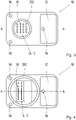
Fig. 2 zeigt eine Draufsicht eines Steuergeräts von einer Seite gemäß einer Ausführung der vorliegenden Erfindung. -
Fig. 3 zeigt eine Draufsicht eines Steuergeräts von einer der inFig. 2 gezeigten Seite gegenüber liegenden Seite gemäß einer Ausführung der vorliegenden Erfindung. -
Fig. 4 zeigt eine Draufsicht eines Steuergeräts von einer inFig. 3 gezeigten Seite einer weiteren Ausführung der vorliegenden Erfindung. -
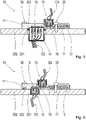
Fig. 5 zeigt eine Schnittdarstellung durch die Punkte A-A ausFiguren 2 und3 eines an einem Getriebegehäuse verbauten Steuergeräts gemäß einer Ausführung der vorliegenden Erfindung. -
Fig. 6 zeigt eine Schnittdarstellung durch die Punkte A-A ausFiguren 2 und4 eines an einem Getriebegehäuse verbauten Steuergeräts gemäß einer weiteren Ausführung der vorliegenden Erfindung. -
Fig. 7 zeigt eine Schnittdarstellung durch die Punkte A-A ausFiguren 2 und3 eines an einem Getriebegehäuse verbauten Steuergeräts gemäß einer weiteren Ausführung der vorliegenden Erfindung. -
Fig. 8 zeigt eine wie inFig. 7 gezeigte Schnittdarstellung eines an einem Getriebegehäuse verbauten Steuergeräts gemäß einer alternativen Ausführung der vorliegenden Erfindung. - In den nachfolgenden Figurenbeschreibungen sind gleiche Elemente bzw. Funktionen mit gleichen Bezugszeichen versehen.
-
Fig. 1 zeigt eine Ansicht eines an einem Getriebegehäuse 200 verbauten Steuergeräts 100 gemäß dem Stand der Technik. Das Steuergerät 100 ist in der Regel ein bestückter Schaltungsträger mit Gehäuse und Stecker 130 und ist z.B. als Anbausteuergerät 100 an einem Aggregat, z.B. einem Automatikgetriebe, bzw. einem entsprechenden Gehäuse 200 verschraubt. Dabei werden über zwei Steckverbindungen am Stecker 130 zwei Kabelsätze zum Getriebe 123 und zum Fahrzeug 124 verbunden. Getriebeseitig wird wiederum über eine Steckverbindung 120 die Anbindung an Komponenten im Getriebeinnenraum, z.B. Sensoren, Ventile, Motoren, über die Steckeröffnung 201 im Gehäuse 200 hergestellt. - Die Grundidee der vorliegenden Erfindung ist es, ein Aufbaukonzept für ein Steuergerät 100 zu wählen, bei dem das Steuergerät sehr nahe an einer Steckeröffnung 201 eines Aggregats, z.B. eines Automatikgetriebes oder eines anderen Getriebes, bzw. eines Getriebegehäuses 200 an dessen Außen- oder Innenseite verbaut wird. Es kann auch eine zusätzliche Öffnung in das Gehäuse eingebracht werden, wenn z.B. keine der vorhandenen Öffnungen verendet werden kann. Im Steuergerät sind sowohl der getriebe- als auch der fahrzeugseitige Stecker bzw. Kabelsätze integriert. Die Elektronik kann durch Technologien mit minimalem Platzbedarf, z.B. durch einen hochintegrierten Chipsatz auf einer Leiterplatte, aufgebaut werden, so dass ein sehr kompaktes Steuergerät entsteht, das sehr wenig Bauraum benötigt.
- Es wird insbesondere ein Einsatz als Anbaugerät am oder als integriertes Modul im Getriebe betrachtet.
-
Fig. 2 zeigt eine Draufsicht eines Steuergeräts 10 von einer Seite gemäß einer Ausführung der vorliegenden Erfindung. In dieser Ausführungsform kann das Steuergerät 10 von außen oder von innen auf das Gehäuse 200, z.B. ein Getriebegehäuse, angebracht werden. - In der Ausführung, bei der das Steuergerät 10 außen an dem Gehäuse 200 angeordnet ist, d.h. auf der Seite außerhalb des Getriebes, d.h. fahrzeugseitig, ist die gezeigte Seite des Steuergeräts dabei die der Gehäuseoberfläche 200 abgewandte Seite, d.h. der Stecker ist der fahrzeugseitige Stecker 13. Dies ist in
Figuren 5 und 6 gezeigt und später beschrieben. - In der Ausführung, bei der das Steuergerät 10 innen an dem Gehäuse 200 angeordnet ist, d.h. auf der Seite innerhalb des Getriebes, d.h. getriebeseitig, ist die gezeigte Seite des Steuergeräts dabei ebenfalls die der Gehäuseoberfläche 200 abgewandte Seite, d.h. der Stecker ist der getriebeseitige Stecker 14. Diese Ausführung ist beispielhaft in
Fig. 7 gezeigt.Fig. 8 _zeigt eine Ausführung, bei der kein getriebeseitiger Stecker verwendet wird, sondern die getriebeseitigen Komponenten direkt mit der Leiterplatte verbunden sind. - Nachfolgend wird der allgemeine Aufbau des Steuergeräts 10 beschrieben, der sowohl für die Ausführungen anwendbar ist, bei denen das Steuergerät außen am Gehäuse angebracht ist, als auch für diejenigen, bei denen das Steuergerät innen am Gehäuse angebracht ist.
- Die in
Fig. 2 gezeigte Seite des Steuergeräts 10 weist einen Stecker 13 oder 14 mit entsprechenden Pins 18 auf, der einen entsprechenden Gegenstecker aufnehmen kann. Die Anordnung des Steckers 13 oder 14 ist derart gewählt, dass er nicht dem inFig. 3 gezeigten Stecker 13 oder 14 direkt gegenüber liegt, d.h. die Stecker würden sich gegenseitig behindern, aber dennoch vorteilhafterweise kurze Verbindungswege über z.B. Leiterbahnen zwischen den Steckern 13 und 14 realisiert werden können. Die Anordnung des inFig. 2 gezeigten Steckers 13 oder 14 hängt von der Bauform und dem Platzbedarf sowie der Anwendung ab und wird vom Fachmann entsprechend vorgegeben. - Ferner weist die in
Fig. 2 gezeigte Seite des Steuergeräts Bohrungen bzw. Anschraubpunkte 16 auf, um das Steuergerät an dem Gehäuse 200 zu verschrauben. Die Anzahl der Bohrungen sollte derart gewählt werden, dass eine stabile Verbindung zwischen Steuergerät 10 und Gehäuse 200 entsteht. Dafür sind beispielsweise drei Bohrungen 16 geeignet, es können aber auch lediglich zwei oder vier oder mehr Bohrungen 16 gewählt werden. Dies ist wiederum vom Fachmann entsprechend der Anwendung zu wählen. - Ferner ist die Leiterplatte des Steuergeräts 10 inklusive dem Stecker mit einer Umspritzung 17 versehen, um einen Schutz vor äußeren Einflüssen zu gewährleisten und um gleichzeitig zumindest eine minimale Versteifung zu bieten. Das Material der Umspritzung 17 sollte derart gewählt werden, dass es eine sichere Dichtung vor Flüssigkeiten, insbesondere Öl, aufweist. Ein geeignetes Material für eine solche Umspritzung 17 ist beispielsweise ein Duroplast.
- Ferner sind in dieser Ausführung mehrere Versteifungsrippen 15 auf der gezeigten Seite des Steuergeräts 10 bzw. innerhalb oder auf der Umspritzung 17 angeordnet. Es können zur Versteifung auch andere Strukturen als die gezeigten Rippen ausgebildet werden. Die Rippen können auf die Umspritzung aufgesetzt oder in der Umspritzung 17 integriert werden. Alternativ ist eine Versteifung auch durch ein zusätzliches Fixierblech möglich, das beim Verschrauben des Steuergeräts 10 an dem Gehäuse 200 befestigt wird.
- Wie später mit Bezug auf
Figuren 7 und 8 genauer beschrieben, muss bei der Ausführung, bei der das Steuergerät 10 innerhalb des Gehäuses 200 angeordnet ist, kein getriebeseitiger Stecker 14 vorhanden sein. Es können vielmehr die im Getrieberaum vorhandenen Komponenten wie z.B. die BUS-Komponenten oder die Stromversorgung, direkt an den Leiterbahnen der Leiterplatte befestigt werden, z.B. durch Löten, Einpressen oder andere bekanntem, geeignete Verfahren. - Fernern kann bei dem fahrzeugseitigen Stecker 13 aus Kostengründen eine Anzahl der Pins 18 auf ein Minimum reduziert werden, z.B. auf zwei Pins für die Spannungsversorgung und zwei Pins für die Busanbindung. Je nach Konfiguration können beispielsweise runde oder rechteckige Stecker mit Rundpins oder rechteckigen Pins verbaut werden. Die Anzahl der Pins 18 und die Art des Steckers 13 sind je nach Platzbedarf und Anwendung vom Fachmann wählbar. Die Anbindung der Pins zur Leiterplatte kann z.B. durch Löten oder Einpressen erfolgen.
-
Fig. 3 zeigt eine Draufsicht eines Steuergeräts 10 von einer der inFig. 2 gezeigten Seite gegenüber liegenden Seite gemäß einer Ausführung der vorliegenden Erfindung. In dieser Ausführungsform kann das Steuergerät 10 von außen oder von innen auf das Gehäuse 200, z.B. ein Getriebegehäuse, angebracht werden. - In der Ausführung, bei der das Steuergerät 10 außen an dem Gehäuse 200 angeordnet ist, d.h. auf der Seite außerhalb des Getriebes, also fahrzeugseitig, ist die in
Fig. 3 gezeigte Seite des Steuergeräts 10 dabei die der Gehäuseoberfläche 200 zugewandte Seite, d.h. diese Seite liegt auf der Oberfläche des Gehäuses 200 auf, wobei der getriebeseitige Stecker 13 durch die Öffnung 201 im Gehäuse 100 hindurchragt. Dies ist inFiguren 5 und 6 gezeigt und später beschrieben. - In der Ausführung, bei der das Steuergerät 10 innen an dem Gehäuse 200 angeordnet ist, d.h. auf der Seite innerhalb des Getriebes, d.h. getriebeseitig, ist die gezeigte Seite des Steuergeräts dabei ebenfalls die der Gehäuseoberfläche 200 zugewandte Seite, wobei hier der fahrzeugseitige Stecker 13 durch die Öffnung 201 im Gehäuse 100 hindurchragt. Diese Ausführung ist beispielhaft in
Figuren 7 und 8 gezeigt. - Die in
Fig. 3 gezeigte Seite des Steuergeräts 10 weist einen Stecker auf, der einen entsprechenden Gegenstecker aufnehmen kann. Die Anordnung des Steckers ist derart gewählt, dass er nicht dem inFig. 2 gezeigten Stecker direkt gegenüber liegt, diesen also nicht behindert, aber dennoch kurze Verbindungswege über z.B. Leiterbahnen zwischen den beiden Steckern 13 und 14 realisiert werden können. Wie bereits oben erwähnt hängt die Anordnung des Steckers von der Bauform und dem Platzbedarf sowie der Anwendung ab und wird vom Fachmann entsprechend vorgegeben. - Es können bei jeder der Ausführungen beide Stecker 13 und 14, also der getriebe- und der fahrzeugseitige Stecker, derart gewählt werden, dass beide so nahe aneinander angeordnet sind, dass sie innerhalb des Bereichs der Bohrung für die Steckeröffnung 201 im Getriebegehäuse 200 liegen, wie in
Figuren 2 und4 als gestrichelte Linie gezeigt und inFig. 6 im Schnitt zu sehen, so dass weiterer Platz eingespart werden kann. Diese Ausführung der Stecker 13 und 14 kann auch für die Ausführung des Steuergeräts 10, das an der Innenseite des Gehäuses 200 angeordnet ist, gewählt werden und wird in den Figuren nicht gezeigt. - Vorteilhafterweise wird die Form des Steckers 13 oder 14 derart gewählt, dass er in eine in dem Getriebegehäuse 200 vorhandene Öffnung, z.B. die in
Fig. 1 gezeigte, Öffnung für den Getriebestecker 201 nach dem Stand der Technik passt, der Stecker 14 also eine runde Form aufweist. Alternativ kann stattdessen der Stecker 13 und/oder 14 auch eine rechteckige Form oder eine andere geeignete Form aufweisen und derart platziert sein, dass der fahrzeugseitige Stecker 13 auf der anderen Seite des Steuergeräts direkt neben dem Stecker 14 innerhalb der vorhandenen Bohrung bzw. Öffnung im Getriebegehäuse 200 angeordnet sein kann, wie inFiguren 2 und4 gezeigt. Hierdurch erfolgt eine Platzeinsparung. Die Wahl der Form des Steckers 13 und 14 ist abhängig von der Anwendung. Je nach Konfiguration können Stecker mit Rundpins oder rechteckigen Pins verwendet werden. Die Anzahl und die Art der Pins, sowie die Art bzw. Form des Steckers 13 und 14 sind je nach Platzbedarf und Anwendung vom Fachmann wählbar. Die Anbindung der Pins zur Leiterplatte kann z.B. durch Löten oder Einpressen erfolgen. - In
Figuren 3 und 4 ist ferner jeweils eine Dichtung 202 gezeigt, die als Formdichtung oder als kostengünstiger O-Ring ausgeführt sein kann, um eine Abdichtung des Steckers 13 oder 14 zusätzlich zur Umspritzung 17 bzw. zwischen der Öffnung 201 im Getriebegehäuse 200 und den darin angeordneten Bauelementen, z.B. dem fahrzeugseitigen und/oder dem getriebeseitigen Stecker 13 bzw. 14, sicherzustellen. Die Art der Dichtung 202 wird je nach Art bzw. Form des Steckers gewählt. Bei einem runden Stecker können einer oder mehrere O-Ringe als Dichtung 202 verwendet werden. Bei einem Stecker, der eine andere Form aufweist als rund, z.B. rechteckig, kann eine Ausnehmung in der Umspritzung 17 außerhalb der Öffnung 201 im Gehäuse gebildet werden, in die eine Formdichtung eingefügt wird. Die Formdichtung kann in die Ausnehmung eingespritzt werden oder als ein Bauteil darin angeordnet werden. Sie sollte aus einem anderen Material als die Umspritzung bestehen, bevorzugt elastisch sein. Je nachdem, welche Art an Steckern gedichtet werden müssen, kann somit eine axiale oder radiale Dichtung erfolgen. - Allerdings kann je nach Anwendung auch keine zusätzliche Abdichtung des Steckers erwünscht oder nötig sein.
- In
Figuren 3 und 4 sind ebenfalls Bohrungen 16 gezeigt, um das Steuergerät an dem Gehäuse 200 zu verschrauben. Diese Bohrungen 16 entsprechen den Bohrungen auf der inFig. 2 gezeigten Seite, d.h. sie liegen an derselben Stelle wie die Bohrungen 16 inFig. 2 . - Bohrungen 16 mit zugehörigen Verschraubungen 30, siehe
Figuren 5 bis 8 , haben den Vorteil, dass sie wieder lösbar sind, d.h. dass das Steuergerät 10 austauschbar ist. Allerdings können auch andere Befestigungsmethoden angewendet werden, z.B. ein Verkleben. Die Art der Befestigung ist je nach Anwendung vom Fachmann zu wählen und nicht auf die genannten Arten beschränkt. - Wie in
Figuren 5 bis 8 zu erkennen, ist an dem Bereich der Leiterplatte 11 des Steuergeräts 10, an dem die Elektronikkomponenten angeordnet sind, auf der Seite, die an der Gehäuseoberfläche 200 anliegt, eine Kühlplatte 12 integriert, die an eine metallische Fläche am Aggregat bzw. an der Gehäuseoberfläche 200 zur Abführung der Verlustwärme angeordnet ist. Die elektronischen Bauelemente können auf der Leiterplatte 11 einseitig oder doppelseitig bestückt werden. Abhängig von dem zur Verfügung stehenden Bauraum kann die Leiterplatte 11 über tiefengefräste Bereiche auch in verschiedenen Winkeln gebogen verbaut werden. -
Figuren 5 und 6 zeigen jeweils eine Schnittdarstellung durch die Punkte A-A eines an der Außenseite eines Getriebegehäuses 200 verbauten Steuergeräts 10, wie bereits mit Bezug aufFiguren 2 bis 4 beschrieben, wobei gleiche Bezugszeichen dieselben Komponenten bezeichnen und hier nicht im Einzelnen detailliert wiederholt werden. - Die Pins 18 der Stecker 13, 14 sind direkt mit den korrespondierenden Leiterbahnen (nicht dargestellt) der Leiterplatte verbunden. Dadurch ergeben sich kurze Signalwege.
-
Fig. 5 zeigt die Ausführung, bei welcher der getriebeseitige Stecker 14 als runder Stecker ausgeführt ist und in die Öffnung des Gehäuses 201 eingepasst ist.Fig. 6 zeigt die Ausführung, bei welcher der getriebeseitige Stecker 14 dieselbe Ausführung aufweist wie der fahrzeugseitige Stecker 13, d.h. in diesem Fall länglich rechteckig, so dass beide Stecker innerhalb des Bereichs der Öffnung 201 im Gehäuse angeordnet sind, allerdings auf sich gegenüber liegenden Seiten des Steuergeräts 10. - Gezeigt sind in
Figuren 5 und 6 zusätzlich Verschraubungen 30, welche durch die Bohrungen 16 auf der Ober- und Unterseite des Steuergeräts 10 durchgeführt sind und das Steuergerät 10 mit dem Gehäuse 200 verbinden. Die Art der Verschraubungen 30 kann beliebig gewählt werden, solange die gewünschte Verbindung zwischen Steuergerät 10 und Gehäuse 200 hergestellt wird. - Ferner ist in
Fig. 5 zu sehen, dass die Dichtung 202 zwischen dem Stecker 14 und der Gehäusewand innerhalb der Öffnung 201 im Gehäuse angeordnet ist. InFig. 6 ist die Dichtung 202 hingegen außerhalb der Öffnung 201 im Gehäuse angeordnet, da in dieser Ausführung kein runder Stecker verwendet wird, bei dem mit Hilfe eines oder mehrerer O-Ringe eine Abdichtung erfolgen kann. Wie oben beschrieben hängt die Wahl der Art der Dichtung 202 von der Art und Form des bzw. der Stecker ab. -
Figuren 7 und 8 zeigen eine Schnittdarstellung durch die Punkte A-A eines an der Innenseite des Getriebegehäuses 200 verbauten Steuergeräts 10 gemäß einer alternativen Ausführung der vorliegenden Erfindung. Es werden dieselben Bezugszeichen für dieselben Komponenten wie für die vorherigen Figuren verwendet und deren Beschreibung nicht im Einzelnen detailliert wiederholt. - Im Unterschied zu dem in
Figuren 5 und 6 gezeigten Ausführungsbeispiel wird in diesem Ausführungsbeispiel das Steuergerät 10 innerhalb des Gehäuses 200 angeordnet. Wie inFiguren 7 und 8 zu sehen ist, ist die Kühlplatte 12 wie auch inFiguren 5 und 6 auf der Seite des Steuergeräts angeordnet, die dem Gehäuse zugewandt ist, um die auf der Leiterplatte 11 angeordneten Elektronikkomponenten zu kühlen. Die Verschraubungen 30 sind wie inFiguren 5 und 6 ausgeführt, das heißt, sie sind durch Bohrungen durchgeführt, um das Steuergerät 10 mit dem Gehäuse zu verbinden. Der einzige Unterschied ist, dass die Verschraubungen 30 durch die Bohrungen 16 von der Innenseite des Gehäuses 200 erfolgen, wobei auch andere Verschraubungen gewählt werden könnten, die von der fahrzeugseitigen Seite verschraubt werden. - Wie ebenfalls vorher für den getriebeseitigen Stecker 14 beschrieben kann der fahrzeugseitige Stecker 13 durch die Öffnung 201 im Gehäuse 200 geführt werden und mit einer Dichtung 202, z.B. einem Formschluss oder einem bzw. mehreren O-Ringen, abgedichtet werden. Die Leiterplatte 11 kann ein- oder beidseitig mit Bauelementen bestückt sein und ist wie in den anderen Ausführungsbeispielen durch eine Umspritzung 17 vor äußeren Einflüssen geschützt.
- In
Fig. 7 ist ferner ein getriebeseitiger Stecker 14 gezeigt, wobei dieser in dieser Ausführung nicht unbedingt nötig ist. Vielmehr kann eine Anbindung der mit dem Steuergerät zu verbindenden Sensoren, Aktoren, etc. innerhalb des Getriebes direkt an der Leiterplatte z.B. durch Löten, Schweißen, Einpressen oder andere geeignete Verfahren erfolgen, wie inFig. 8 gezeigt. Somit können Bauteile eingespart und ein kostengünstigeres System realisiert werden. - Bei den in
Figuren 7 und 8 gezeigten Ausführungsbeispielen ist es auch möglich, den fahrzeugseitigen Stecker 13 wie in den vorherigen Ausführungsbeispielen nicht rund auszuführen, sondern z.B. rechteckig. Die Form des Steckers 13 ist nicht beschränkt, es kann jeder bzw. jede für die entsprechende Anwendung geeigneter Stecker 13 bzw. Steckerform verwendet werden. Sowohl in der Ausführung mit einem fahrzeugseitigen und einem getriebeseitigen Stecker 13 und 14, als auch in der Ausführung ohne den getriebeseitigen Stecker 14 können die bzw. der Stecker wie inFiguren 2 und4 gezeigt innerhalb des Bereichs der Gehäuseöffnung 201 auf sich gegenüber liegenden Seiten angeordnet sein, um Platz zu sparen. - Die vorliegende Erfindung weist mehrere Vorteile gegenüber bekannten Steuergeräten beim Verbau an Gehäusen, insbesondere Getriebegehäusen, auf. Es können beispielsweise einfache, kostengünstige, nicht dichte Stecker mit Flachpins eingesetzt werden, oder zur Bereitstellung einer Öldichtheit eine Abdichtung der Pins 18 durch Duroplast-Umspritzung in Kombination mit einer Formdichtung oder einem oder mehreren O-Ringen erfolgen. Das heißt, es können sowohl axiale als auch radiale Dichtungen realisiert werden.
- Ferner ist eine signifikante Einsparung von Einzelteilen bzw. eine Reduzierung der durch Zulieferer bereit gestellten Komponenten möglich, so dass wiederum Kosten eingespart werden können.
- Zusätzlich wird eine Einsparung des Kabelsatzes zwischen der Verbindung Getriebe und angebauten Steuergerät ermöglicht, da hier Bahnen innerhalb der Leiterplatte als Verbindung dienen können.
- Durch die Bauform kann eine optimale thermische Anbindung zur Wärmeableitung erreicht werden, da nur eine kleine Kühlfläche benötigt wird bzw. durch Tiefenfräsung teilweise eine Ausbildung von 3D-Strukturen möglich ist.
- Durch die Option, dass das Steuergerät innerhalb des Getriebes verbaut werden kann, aber nicht muss, kann eine optimale Platzausnutzung erreicht werden. Es muss zum Beispiel im Getrieberaum kein weiterer Platz für die Elektronik vorgehalten werden, da diese im Steuergerät integriert ist, wobei das Steuergerät nur einen minimalen Bauraum benötigt.
-
- 10, 100
- (Anbau-)Steuergerät
- 11
- Leiterplatte
- 12
- Kühlplatte
- 13
- fahrzeugseitiger Stecker
- 14
- getriebeseitiger Stecker
- 15
- Versteifungsrippen
- 16
- Anschraubpunkte
- 17
- Umspritzung
- 18
- Pins
- 200
- Getriebegehäuse bzw. Wand des Getriebegehäuses
- 201
- Öffnung im Getriebegehäuse für Getriebestecker
- 202
- Dichtung
- 120
- Getriebestecker
- 130
- Stecksockel für fahrzeugseitige und getriebeseitige Stecker
- 123
- Kabelsatz zum Getriebe
- 124
- Kabelsatz zum Fahrzeug
- 30
- Verschraubung
Claims (9)
- Steuergerät (10), insbesondere Getriebesteuergerät (10), das dazu eingerichtet ist, auf einer Außenseite oder einen Innenseite eines Gehäuses (200), insbesondere eines Getriebegehäuses (200), an der Gehäuseoberfläche 200 anliegend befestigt zu werden, wobei das Steuergerät (10) eine Leiterplatte (11) sowie zumindest einen auf der Leiterplatte (11) angeordneten und mit seinen Pins (18) mit korrespondierenden Leiterbahnen der Leiterplatte verbundenen Stecker (13; 14) umfasst, der dazu eingerichtet ist, durch eine Öffnung (201) in dem Gehäuse (200) zu ragen und über an der Leiterplatte (11) angeordnete Leiterbahnen eine elektrische und/oder Signal-Verbindung zwischen der Außenseite und der Innenseite des Gehäuses (200) herzustellen, wobei eine Umspritzung (17) zumindest die Leiterplatte (11) und den bzw. die Stecker (13; 14) umgibt.
- Steuergerät (10) nach Anspruch 1, wobei das Steuergerät (10) an der Außenseite des Gehäuses (200) angeordnet ist und der Stecker ein getriebeseitiger Stecker (14) ist.
- Steuergerät (10) nach Anspruch 2, wobei die Leiterplatte (11) auf der dem getriebeseitigen Stecker (14) gegenüber liegenden Seite einen fahrzeugseitigen Stecker (13) aufweist, der über die Leiterbahnen mit dem getriebeseitigen Stecker (14) verbunden ist.
- Steuergerät (10) nach Anspruch 1, wobei das Steuergerät (10) an der Innenseite des Gehäuses (200) angeordnet ist und der Stecker ein fahrzeugseitiger Stecker (13) ist.
- Steuergerät (10) nach Anspruch 4, wobei die Leiterplatte (11) auf der dem fahrzeugseitigen Stecker (13) gegenüber liegenden Seite einen getriebeseitigen Stecker (14) aufweist, der über die Leiterbahnen mit dem fahrzeugseitigen Stecker (13) verbunden ist.
- Steuergerät (10) nach Anspruch 4, wobei die mit dem fahrzeugseitigen Stecker (13) verbundenen Leiterbahnen der Leiterplatte (11) direkt mit getriebeseitigen Komponenten verbunden sind.
- Steuergerät (10) nach Anspruch 6, wobei die Verbindung zwischen Leiterbahnen und Komponenten im Gehäuseinnenraum mittels Löten, Einpressen, Verschweißen erfolgt und/oder die Komponenten im Gehäuseinnenraum Signalanbindungen, insbesondere Busanbindungen, insbesondere von Sensoren, Aktoren, Ventile und/oder Motoren, und/oder eine Spannungs- bzw. Stromversorgung umfassen.
- Steuergerät (10) nach einem der vorhergehenden Ansprüche, wobei den durch die Öffnung (201) des Gehäuses (200) ragenden Stecker (13; 14) eine Dichtung (202), insbesondere ein oder mehrere O-Ringe oder eine in einer Ausnehmung der Umspritzung (17) angeordnete Formdichtung, umgibt.
- Steuergerät (10) nach einem der vorhergehenden Ansprüche, wobei die Leiterplatte (11) darauf angeordnete elektrische und/oder elektronische Bauelemente umfasst, und in dem Bereich der elektrischen und/oder elektronischen Bauelemente auf der Seite der Leiterplatte (11), die dem Gehäuse zugewandt ist, eine Kühleinrichtung (12), insbesondere eine Kühlplatte, angeordnet ist.
Applications Claiming Priority (2)
| Application Number | Priority Date | Filing Date | Title |
|---|---|---|---|
| DE102016203718.8A DE102016203718A1 (de) | 2016-03-08 | 2016-03-08 | Steuergerät |
| PCT/EP2017/054112 WO2017153174A1 (de) | 2016-03-08 | 2017-02-23 | Steuergerät |
Publications (2)
| Publication Number | Publication Date |
|---|---|
| EP3427557A1 EP3427557A1 (de) | 2019-01-16 |
| EP3427557B1 true EP3427557B1 (de) | 2022-04-06 |
Family
ID=58162560
Family Applications (1)
| Application Number | Title | Priority Date | Filing Date |
|---|---|---|---|
| EP17707238.6A Active EP3427557B1 (de) | 2016-03-08 | 2017-02-23 | Steuergerät |
Country Status (6)
| Country | Link |
|---|---|
| US (1) | US10966330B2 (de) |
| EP (1) | EP3427557B1 (de) |
| KR (1) | KR102688785B1 (de) |
| CN (1) | CN108702848A (de) |
| DE (1) | DE102016203718A1 (de) |
| WO (1) | WO2017153174A1 (de) |
Families Citing this family (5)
| Publication number | Priority date | Publication date | Assignee | Title |
|---|---|---|---|---|
| DE102018203235A1 (de) | 2018-03-05 | 2019-09-05 | Zf Friedrichshafen Ag | Elektromotor zur Betätigung von Schaltelementen für Automatikgetriebe und System mit solchen Elektromotoren |
| JP6687291B1 (ja) * | 2019-01-22 | 2020-04-22 | 三菱電機株式会社 | 電気機器 |
| DE102019206525A1 (de) * | 2019-05-07 | 2020-11-12 | Zf Friedrichshafen Ag | Getriebe mit Leistungselektronikmodul |
| DE102023201898A1 (de) | 2023-03-02 | 2024-09-05 | Robert Bosch Gesellschaft mit beschränkter Haftung | Stecker-Sensor-Baugruppe, Gehäuse für ein Tankventil oder einen Tankendstopfen mit einer Stecker-Sensor-Baugruppe, Tankventil sowie Tankendstopfen |
| DE102024130864A1 (de) | 2024-10-23 | 2026-04-23 | Valeo Schalter Und Sensoren Gmbh | Steuergerätanordnung und Steuergerät für ein Kraftfahrzeug |
Citations (1)
| Publication number | Priority date | Publication date | Assignee | Title |
|---|---|---|---|---|
| US20060075848A1 (en) * | 2004-09-29 | 2006-04-13 | Denso Corporation | Automatic transmission |
Family Cites Families (27)
| Publication number | Priority date | Publication date | Assignee | Title |
|---|---|---|---|---|
| JPH0722722A (ja) * | 1993-07-05 | 1995-01-24 | Mitsubishi Electric Corp | 樹脂成形タイプの電子回路装置 |
| DE4334595C1 (de) | 1993-10-11 | 1995-04-27 | Siemens Ag | Steuerung für ein Kraftfahrzeug |
| DE19515622C2 (de) * | 1995-04-28 | 2000-06-08 | Telefunken Microelectron | Steuermodul von Kraftfahrzeugen |
| JP3412360B2 (ja) * | 1995-10-06 | 2003-06-03 | アイシン・エィ・ダブリュ株式会社 | 自動変速機 |
| DE19848732A1 (de) | 1998-10-22 | 2000-04-27 | Zahnradfabrik Friedrichshafen | Elektrische Steckverbindung |
| DE19955603C1 (de) | 1999-11-18 | 2001-02-15 | Siemens Ag | Steuergerät für ein Kraftfahrzeug und Herstellungsverfahren |
| US6307749B1 (en) * | 2000-10-23 | 2001-10-23 | Delphi Technologies, Inc. | Overmolded electronic module with underfilled surface-mount components |
| US6739042B2 (en) * | 2000-12-15 | 2004-05-25 | Siemens Vdo Automotive Corporation | Method for assembling a mechatronics sensor |
| DE10134053A1 (de) * | 2001-07-13 | 2003-02-13 | Zahnradfabrik Friedrichshafen | Elektrischer Zentralstecker für ein elektronisches Steuergerät |
| JP4466256B2 (ja) * | 2004-07-29 | 2010-05-26 | アイシン・エィ・ダブリュ株式会社 | 自動変速機用電子制御装置 |
| JP4374617B2 (ja) * | 2004-09-29 | 2009-12-02 | 株式会社デンソー | 自動変速機 |
| JP4539383B2 (ja) * | 2005-03-14 | 2010-09-08 | トヨタ自動車株式会社 | 動力伝達装置のコントロールユニット取付構造 |
| JP4619257B2 (ja) * | 2005-10-03 | 2011-01-26 | トヨタ自動車株式会社 | 自動変速機 |
| JP5046516B2 (ja) * | 2005-12-20 | 2012-10-10 | プライムアースEvエナジー株式会社 | 電池パック |
| DE102006001890A1 (de) * | 2006-01-14 | 2007-08-02 | Zf Friedrichshafen Ag | Elektronisches Anbau-Steuergerät |
| DE102006054279A1 (de) * | 2006-11-17 | 2008-05-21 | Zf Friedrichshafen Ag | Getriebesteuerung und Verfahren zur Montage einer Getriebesteuerung |
| DE112007001716T5 (de) * | 2006-11-24 | 2009-05-07 | Aisin AW Co., Ltd., Anjo | Automatikgetriebesteuereinheit und Automatikgetriebe mit diesem |
| CN101663511B (zh) * | 2007-05-28 | 2013-03-06 | 爱信艾达株式会社 | 自动变速器用控制单元冷却装置 |
| JP5592766B2 (ja) * | 2010-11-18 | 2014-09-17 | 日立オートモティブシステムズ株式会社 | 自動車用制御装置 |
| US8818612B2 (en) * | 2011-09-14 | 2014-08-26 | Robert Bosch Gmbh | On-board diagnostic connector module and vehicle diagnostic system |
| DE102012213916A1 (de) * | 2011-11-08 | 2013-05-08 | Robert Bosch Gmbh | Elektronikmodul für ein Steuergerät |
| DE102011088031A1 (de) * | 2011-12-08 | 2013-06-13 | Robert Bosch Gmbh | Getriebesteuermodul |
| DE102012204002B4 (de) * | 2012-03-14 | 2024-11-21 | Zf Friedrichshafen Ag | Steckervorrichtung für eine Leiterplatte eines Steuergeräts für ein Fahrzeuggetriebe, Steuersystem für ein Fahrzeuggetriebe und Verfahren zum Montieren eines Steuersystems für ein Fahrzeuggetriebe |
| DE102012213917A1 (de) * | 2012-08-06 | 2014-02-20 | Robert Bosch Gmbh | Bauelemente-Ummantelung für ein Elektronikmodul |
| WO2016114222A1 (ja) * | 2015-01-14 | 2016-07-21 | 日立オートモティブシステムズ株式会社 | 電子制御装置 |
| WO2017098826A1 (ja) * | 2015-12-10 | 2017-06-15 | 日立オートモティブシステムズ株式会社 | 電子制御装置 |
| JP6554132B2 (ja) * | 2017-03-31 | 2019-07-31 | 本田技研工業株式会社 | 樹脂ケース |
-
2016
- 2016-03-08 DE DE102016203718.8A patent/DE102016203718A1/de active Pending
-
2017
- 2017-02-23 EP EP17707238.6A patent/EP3427557B1/de active Active
- 2017-02-23 KR KR1020187028715A patent/KR102688785B1/ko active Active
- 2017-02-23 WO PCT/EP2017/054112 patent/WO2017153174A1/de not_active Ceased
- 2017-02-23 US US16/083,601 patent/US10966330B2/en not_active Expired - Fee Related
- 2017-02-23 CN CN201780013287.3A patent/CN108702848A/zh active Pending
Patent Citations (1)
| Publication number | Priority date | Publication date | Assignee | Title |
|---|---|---|---|---|
| US20060075848A1 (en) * | 2004-09-29 | 2006-04-13 | Denso Corporation | Automatic transmission |
Also Published As
| Publication number | Publication date |
|---|---|
| KR20180118768A (ko) | 2018-10-31 |
| US10966330B2 (en) | 2021-03-30 |
| EP3427557A1 (de) | 2019-01-16 |
| CN108702848A (zh) | 2018-10-23 |
| DE102016203718A1 (de) | 2017-09-14 |
| WO2017153174A1 (de) | 2017-09-14 |
| US20190082545A1 (en) | 2019-03-14 |
| KR102688785B1 (ko) | 2024-07-25 |
Similar Documents
| Publication | Publication Date | Title |
|---|---|---|
| EP0742765B1 (de) | Blockiergeschützte bremsanlage | |
| DE102017202765A1 (de) | Steuervorrichtung für einen Elektromotor | |
| DE102005059941A1 (de) | Elektrohydraulische Druckregelvorrichtung für Kraftfahrzeugbremssysteme | |
| WO2017153174A1 (de) | Steuergerät | |
| DE102019106082A1 (de) | Schaltschranksystem mit dichtungseinsatz | |
| WO2018149450A1 (de) | Elektronikgehäuse für einen e-achsen-antrieb und e-achse mit elektronikgehäuse | |
| EP2774462A1 (de) | Elektronikmodul zum betrieb im getriebe | |
| EP3175204B1 (de) | Sensoreinrichtung für ein kraftfahrzeug | |
| WO2006087225A1 (de) | Antenne und mittel zum befestigen der antenne auf einem fahrzeug sowie zum anschliessen der antenne an ein oder mehrere kabel eines im fahrzeug verlegten kabelbaumes | |
| DE102012102842B4 (de) | Befestigung und Abdichtung von Steckanschlussmodulen in einer Gehäusewand | |
| EP3284160A1 (de) | Aktor für eine kraftfahrzeugkupplung mit einem träger mit darin gehaltertem stecker und hybridmodul mit solchem aktor | |
| DE102015203592A1 (de) | Elektronische Einheit mit einer Steckeranordnung | |
| EP2893785B1 (de) | Anordnung eines elektrischen steuergeräts an eine schaltplatte | |
| EP4144571A1 (de) | Modulare ladeschnittstelle | |
| DE102017211008A1 (de) | Elektronisches Steuergerät | |
| DE102011007300A1 (de) | Steuergerät für ein Getriebe eines Fahrzeugs und Verfahren zur Montage eines Steuergeräts für ein Getriebe eines Fahrzeugs an einem Getriebeelement | |
| DE102019102713A1 (de) | Antriebseinheit | |
| DE102015206616A1 (de) | Leiterplatte zur elektronischen Funktionssteuerung für ein Fahrzeug | |
| DE102007002193B4 (de) | Mehrteiliges Kontaktierungsbauteil | |
| DE10161102A1 (de) | Leitungs-Steckverbindung für elektrisches Steuergerät sowie Herstellungsverfahren | |
| DE10134053A1 (de) | Elektrischer Zentralstecker für ein elektronisches Steuergerät | |
| WO2006042774A1 (de) | Stecksystem, insbesondere für mechatronische getriebe- oder motorsteuerungen | |
| DE102013212164A1 (de) | Anordnung zur Getriebesteuerung | |
| DE102011017745B4 (de) | Gehäuse für eine Leiterplatte eines Steuergeräts für ein Getriebe eines Fahrzeugs, Steuergerät sowie Steuersystem für ein Getriebe eines Fahrzeugs und Verfahren zum Montieren eines Steuersystems für ein Getriebe eines Fahrzeugs | |
| DE102011017747A1 (de) | Steuergerät, Steuersystem und Verfahren zum Verbinden eines Steuergeräts für ein Getriebe eines Fahrzeugs mit weiteren Getriebesteuerungselementen |
Legal Events
| Date | Code | Title | Description |
|---|---|---|---|
| STAA | Information on the status of an ep patent application or granted ep patent |
Free format text: STATUS: UNKNOWN |
|
| STAA | Information on the status of an ep patent application or granted ep patent |
Free format text: STATUS: THE INTERNATIONAL PUBLICATION HAS BEEN MADE |
|
| PUAI | Public reference made under article 153(3) epc to a published international application that has entered the european phase |
Free format text: ORIGINAL CODE: 0009012 |
|
| STAA | Information on the status of an ep patent application or granted ep patent |
Free format text: STATUS: REQUEST FOR EXAMINATION WAS MADE |
|
| 17P | Request for examination filed |
Effective date: 20180816 |
|
| AK | Designated contracting states |
Kind code of ref document: A1 Designated state(s): AL AT BE BG CH CY CZ DE DK EE ES FI FR GB GR HR HU IE IS IT LI LT LU LV MC MK MT NL NO PL PT RO RS SE SI SK SM TR |
|
| AX | Request for extension of the european patent |
Extension state: BA ME |
|
| DAV | Request for validation of the european patent (deleted) | ||
| DAX | Request for extension of the european patent (deleted) | ||
| STAA | Information on the status of an ep patent application or granted ep patent |
Free format text: STATUS: EXAMINATION IS IN PROGRESS |
|
| 17Q | First examination report despatched |
Effective date: 20210303 |
|
| REG | Reference to a national code |
Ref country code: DE Ref legal event code: R079 Ref document number: 502017012909 Country of ref document: DE Free format text: PREVIOUS MAIN CLASS: H05K0005000000 Ipc: F16H0057000000 |
|
| RIC1 | Information provided on ipc code assigned before grant |
Ipc: F16H 61/00 20060101ALI20211013BHEP Ipc: H05K 5/00 20060101ALI20211013BHEP Ipc: F16H 57/00 20120101AFI20211013BHEP |
|
| GRAP | Despatch of communication of intention to grant a patent |
Free format text: ORIGINAL CODE: EPIDOSNIGR1 |
|
| STAA | Information on the status of an ep patent application or granted ep patent |
Free format text: STATUS: GRANT OF PATENT IS INTENDED |
|
| INTG | Intention to grant announced |
Effective date: 20211126 |
|
| GRAS | Grant fee paid |
Free format text: ORIGINAL CODE: EPIDOSNIGR3 |
|
| GRAA | (expected) grant |
Free format text: ORIGINAL CODE: 0009210 |
|
| STAA | Information on the status of an ep patent application or granted ep patent |
Free format text: STATUS: THE PATENT HAS BEEN GRANTED |
|
| AK | Designated contracting states |
Kind code of ref document: B1 Designated state(s): AL AT BE BG CH CY CZ DE DK EE ES FI FR GB GR HR HU IE IS IT LI LT LU LV MC MK MT NL NO PL PT RO RS SE SI SK SM TR |
|
| REG | Reference to a national code |
Ref country code: GB Ref legal event code: FG4D Free format text: NOT ENGLISH |
|
| REG | Reference to a national code |
Ref country code: CH Ref legal event code: EP |
|
| REG | Reference to a national code |
Ref country code: AT Ref legal event code: REF Ref document number: 1481632 Country of ref document: AT Kind code of ref document: T Effective date: 20220415 |
|
| REG | Reference to a national code |
Ref country code: IE Ref legal event code: FG4D Free format text: LANGUAGE OF EP DOCUMENT: GERMAN |
|
| REG | Reference to a national code |
Ref country code: DE Ref legal event code: R096 Ref document number: 502017012909 Country of ref document: DE |
|
| REG | Reference to a national code |
Ref country code: LT Ref legal event code: MG9D |
|
| REG | Reference to a national code |
Ref country code: NL Ref legal event code: MP Effective date: 20220406 |
|
| PG25 | Lapsed in a contracting state [announced via postgrant information from national office to epo] |
Ref country code: NL Free format text: LAPSE BECAUSE OF FAILURE TO SUBMIT A TRANSLATION OF THE DESCRIPTION OR TO PAY THE FEE WITHIN THE PRESCRIBED TIME-LIMIT Effective date: 20220406 |
|
| PG25 | Lapsed in a contracting state [announced via postgrant information from national office to epo] |
Ref country code: SE Free format text: LAPSE BECAUSE OF FAILURE TO SUBMIT A TRANSLATION OF THE DESCRIPTION OR TO PAY THE FEE WITHIN THE PRESCRIBED TIME-LIMIT Effective date: 20220406 Ref country code: PT Free format text: LAPSE BECAUSE OF FAILURE TO SUBMIT A TRANSLATION OF THE DESCRIPTION OR TO PAY THE FEE WITHIN THE PRESCRIBED TIME-LIMIT Effective date: 20220808 Ref country code: NO Free format text: LAPSE BECAUSE OF FAILURE TO SUBMIT A TRANSLATION OF THE DESCRIPTION OR TO PAY THE FEE WITHIN THE PRESCRIBED TIME-LIMIT Effective date: 20220706 Ref country code: LT Free format text: LAPSE BECAUSE OF FAILURE TO SUBMIT A TRANSLATION OF THE DESCRIPTION OR TO PAY THE FEE WITHIN THE PRESCRIBED TIME-LIMIT Effective date: 20220406 Ref country code: HR Free format text: LAPSE BECAUSE OF FAILURE TO SUBMIT A TRANSLATION OF THE DESCRIPTION OR TO PAY THE FEE WITHIN THE PRESCRIBED TIME-LIMIT Effective date: 20220406 Ref country code: GR Free format text: LAPSE BECAUSE OF FAILURE TO SUBMIT A TRANSLATION OF THE DESCRIPTION OR TO PAY THE FEE WITHIN THE PRESCRIBED TIME-LIMIT Effective date: 20220707 Ref country code: FI Free format text: LAPSE BECAUSE OF FAILURE TO SUBMIT A TRANSLATION OF THE DESCRIPTION OR TO PAY THE FEE WITHIN THE PRESCRIBED TIME-LIMIT Effective date: 20220406 Ref country code: ES Free format text: LAPSE BECAUSE OF FAILURE TO SUBMIT A TRANSLATION OF THE DESCRIPTION OR TO PAY THE FEE WITHIN THE PRESCRIBED TIME-LIMIT Effective date: 20220406 Ref country code: BG Free format text: LAPSE BECAUSE OF FAILURE TO SUBMIT A TRANSLATION OF THE DESCRIPTION OR TO PAY THE FEE WITHIN THE PRESCRIBED TIME-LIMIT Effective date: 20220706 |
|
| PG25 | Lapsed in a contracting state [announced via postgrant information from national office to epo] |
Ref country code: RS Free format text: LAPSE BECAUSE OF FAILURE TO SUBMIT A TRANSLATION OF THE DESCRIPTION OR TO PAY THE FEE WITHIN THE PRESCRIBED TIME-LIMIT Effective date: 20220406 Ref country code: PL Free format text: LAPSE BECAUSE OF FAILURE TO SUBMIT A TRANSLATION OF THE DESCRIPTION OR TO PAY THE FEE WITHIN THE PRESCRIBED TIME-LIMIT Effective date: 20220406 Ref country code: LV Free format text: LAPSE BECAUSE OF FAILURE TO SUBMIT A TRANSLATION OF THE DESCRIPTION OR TO PAY THE FEE WITHIN THE PRESCRIBED TIME-LIMIT Effective date: 20220406 Ref country code: IS Free format text: LAPSE BECAUSE OF FAILURE TO SUBMIT A TRANSLATION OF THE DESCRIPTION OR TO PAY THE FEE WITHIN THE PRESCRIBED TIME-LIMIT Effective date: 20220806 |
|
| REG | Reference to a national code |
Ref country code: DE Ref legal event code: R097 Ref document number: 502017012909 Country of ref document: DE |
|
| PG25 | Lapsed in a contracting state [announced via postgrant information from national office to epo] |
Ref country code: SM Free format text: LAPSE BECAUSE OF FAILURE TO SUBMIT A TRANSLATION OF THE DESCRIPTION OR TO PAY THE FEE WITHIN THE PRESCRIBED TIME-LIMIT Effective date: 20220406 Ref country code: SK Free format text: LAPSE BECAUSE OF FAILURE TO SUBMIT A TRANSLATION OF THE DESCRIPTION OR TO PAY THE FEE WITHIN THE PRESCRIBED TIME-LIMIT Effective date: 20220406 Ref country code: RO Free format text: LAPSE BECAUSE OF FAILURE TO SUBMIT A TRANSLATION OF THE DESCRIPTION OR TO PAY THE FEE WITHIN THE PRESCRIBED TIME-LIMIT Effective date: 20220406 Ref country code: EE Free format text: LAPSE BECAUSE OF FAILURE TO SUBMIT A TRANSLATION OF THE DESCRIPTION OR TO PAY THE FEE WITHIN THE PRESCRIBED TIME-LIMIT Effective date: 20220406 Ref country code: DK Free format text: LAPSE BECAUSE OF FAILURE TO SUBMIT A TRANSLATION OF THE DESCRIPTION OR TO PAY THE FEE WITHIN THE PRESCRIBED TIME-LIMIT Effective date: 20220406 Ref country code: CZ Free format text: LAPSE BECAUSE OF FAILURE TO SUBMIT A TRANSLATION OF THE DESCRIPTION OR TO PAY THE FEE WITHIN THE PRESCRIBED TIME-LIMIT Effective date: 20220406 |
|
| PLBE | No opposition filed within time limit |
Free format text: ORIGINAL CODE: 0009261 |
|
| STAA | Information on the status of an ep patent application or granted ep patent |
Free format text: STATUS: NO OPPOSITION FILED WITHIN TIME LIMIT |
|
| 26N | No opposition filed |
Effective date: 20230110 |
|
| PG25 | Lapsed in a contracting state [announced via postgrant information from national office to epo] |
Ref country code: AL Free format text: LAPSE BECAUSE OF FAILURE TO SUBMIT A TRANSLATION OF THE DESCRIPTION OR TO PAY THE FEE WITHIN THE PRESCRIBED TIME-LIMIT Effective date: 20220406 |
|
| PG25 | Lapsed in a contracting state [announced via postgrant information from national office to epo] |
Ref country code: SI Free format text: LAPSE BECAUSE OF FAILURE TO SUBMIT A TRANSLATION OF THE DESCRIPTION OR TO PAY THE FEE WITHIN THE PRESCRIBED TIME-LIMIT Effective date: 20220406 |
|
| P01 | Opt-out of the competence of the unified patent court (upc) registered |
Effective date: 20230528 |
|
| PG25 | Lapsed in a contracting state [announced via postgrant information from national office to epo] |
Ref country code: MC Free format text: LAPSE BECAUSE OF FAILURE TO SUBMIT A TRANSLATION OF THE DESCRIPTION OR TO PAY THE FEE WITHIN THE PRESCRIBED TIME-LIMIT Effective date: 20220406 |
|
| REG | Reference to a national code |
Ref country code: CH Ref legal event code: PL |
|
| REG | Reference to a national code |
Ref country code: BE Ref legal event code: MM Effective date: 20230228 |
|
| GBPC | Gb: european patent ceased through non-payment of renewal fee |
Effective date: 20230223 |
|
| PG25 | Lapsed in a contracting state [announced via postgrant information from national office to epo] |
Ref country code: LU Free format text: LAPSE BECAUSE OF NON-PAYMENT OF DUE FEES Effective date: 20230223 Ref country code: LI Free format text: LAPSE BECAUSE OF NON-PAYMENT OF DUE FEES Effective date: 20230228 Ref country code: CH Free format text: LAPSE BECAUSE OF NON-PAYMENT OF DUE FEES Effective date: 20230228 |
|
| REG | Reference to a national code |
Ref country code: IE Ref legal event code: MM4A |
|
| PG25 | Lapsed in a contracting state [announced via postgrant information from national office to epo] |
Ref country code: GB Free format text: LAPSE BECAUSE OF NON-PAYMENT OF DUE FEES Effective date: 20230223 |
|
| PG25 | Lapsed in a contracting state [announced via postgrant information from national office to epo] |
Ref country code: IT Free format text: LAPSE BECAUSE OF FAILURE TO SUBMIT A TRANSLATION OF THE DESCRIPTION OR TO PAY THE FEE WITHIN THE PRESCRIBED TIME-LIMIT Effective date: 20220406 Ref country code: IE Free format text: LAPSE BECAUSE OF NON-PAYMENT OF DUE FEES Effective date: 20230223 Ref country code: GB Free format text: LAPSE BECAUSE OF NON-PAYMENT OF DUE FEES Effective date: 20230223 Ref country code: FR Free format text: LAPSE BECAUSE OF NON-PAYMENT OF DUE FEES Effective date: 20230228 |
|
| PG25 | Lapsed in a contracting state [announced via postgrant information from national office to epo] |
Ref country code: BE Free format text: LAPSE BECAUSE OF NON-PAYMENT OF DUE FEES Effective date: 20230228 |
|
| REG | Reference to a national code |
Ref country code: AT Ref legal event code: MM01 Ref document number: 1481632 Country of ref document: AT Kind code of ref document: T Effective date: 20230223 |
|
| PG25 | Lapsed in a contracting state [announced via postgrant information from national office to epo] |
Ref country code: AT Free format text: LAPSE BECAUSE OF NON-PAYMENT OF DUE FEES Effective date: 20230223 |
|
| PG25 | Lapsed in a contracting state [announced via postgrant information from national office to epo] |
Ref country code: AT Free format text: LAPSE BECAUSE OF NON-PAYMENT OF DUE FEES Effective date: 20230223 |
|
| PG25 | Lapsed in a contracting state [announced via postgrant information from national office to epo] |
Ref country code: BG Free format text: LAPSE BECAUSE OF FAILURE TO SUBMIT A TRANSLATION OF THE DESCRIPTION OR TO PAY THE FEE WITHIN THE PRESCRIBED TIME-LIMIT Effective date: 20220406 |
|
| PG25 | Lapsed in a contracting state [announced via postgrant information from national office to epo] |
Ref country code: BG Free format text: LAPSE BECAUSE OF FAILURE TO SUBMIT A TRANSLATION OF THE DESCRIPTION OR TO PAY THE FEE WITHIN THE PRESCRIBED TIME-LIMIT Effective date: 20220406 |
|
| PG25 | Lapsed in a contracting state [announced via postgrant information from national office to epo] |
Ref country code: CY Free format text: LAPSE BECAUSE OF FAILURE TO SUBMIT A TRANSLATION OF THE DESCRIPTION OR TO PAY THE FEE WITHIN THE PRESCRIBED TIME-LIMIT; INVALID AB INITIO Effective date: 20170223 |
|
| PG25 | Lapsed in a contracting state [announced via postgrant information from national office to epo] |
Ref country code: HU Free format text: LAPSE BECAUSE OF FAILURE TO SUBMIT A TRANSLATION OF THE DESCRIPTION OR TO PAY THE FEE WITHIN THE PRESCRIBED TIME-LIMIT; INVALID AB INITIO Effective date: 20170223 |
|
| PG25 | Lapsed in a contracting state [announced via postgrant information from national office to epo] |
Ref country code: TR Free format text: LAPSE BECAUSE OF FAILURE TO SUBMIT A TRANSLATION OF THE DESCRIPTION OR TO PAY THE FEE WITHIN THE PRESCRIBED TIME-LIMIT Effective date: 20220406 |
|
| PGFP | Annual fee paid to national office [announced via postgrant information from national office to epo] |
Ref country code: DE Payment date: 20260102 Year of fee payment: 10 |