EP3424318A1 - Angelschnurführung, angelrute mit der angelschnurführung und führungsring für die angelschnurführung - Google Patents
Angelschnurführung, angelrute mit der angelschnurführung und führungsring für die angelschnurführung Download PDFInfo
- Publication number
- EP3424318A1 EP3424318A1 EP16892668.1A EP16892668A EP3424318A1 EP 3424318 A1 EP3424318 A1 EP 3424318A1 EP 16892668 A EP16892668 A EP 16892668A EP 3424318 A1 EP3424318 A1 EP 3424318A1
- Authority
- EP
- European Patent Office
- Prior art keywords
- guide
- fishing line
- guide ring
- ring
- fishing
- Prior art date
- Legal status (The legal status is an assumption and is not a legal conclusion. Google has not performed a legal analysis and makes no representation as to the accuracy of the status listed.)
- Granted
Links
Images



Classifications
-
- A—HUMAN NECESSITIES
- A01—AGRICULTURE; FORESTRY; ANIMAL HUSBANDRY; HUNTING; TRAPPING; FISHING
- A01K—ANIMAL HUSBANDRY; AVICULTURE; APICULTURE; PISCICULTURE; FISHING; REARING OR BREEDING ANIMALS, NOT OTHERWISE PROVIDED FOR; NEW BREEDS OF ANIMALS
- A01K87/00—Fishing rods
- A01K87/04—Fishing-line guides on rods, e.g. tips
-
- A—HUMAN NECESSITIES
- A01—AGRICULTURE; FORESTRY; ANIMAL HUSBANDRY; HUNTING; TRAPPING; FISHING
- A01K—ANIMAL HUSBANDRY; AVICULTURE; APICULTURE; PISCICULTURE; FISHING; REARING OR BREEDING ANIMALS, NOT OTHERWISE PROVIDED FOR; NEW BREEDS OF ANIMALS
- A01K87/00—Fishing rods
- A01K87/02—Connecting devices for parts of the rods
-
- F—MECHANICAL ENGINEERING; LIGHTING; HEATING; WEAPONS; BLASTING
- F16—ENGINEERING ELEMENTS AND UNITS; GENERAL MEASURES FOR PRODUCING AND MAINTAINING EFFECTIVE FUNCTIONING OF MACHINES OR INSTALLATIONS; THERMAL INSULATION IN GENERAL
- F16B—DEVICES FOR FASTENING OR SECURING CONSTRUCTIONAL ELEMENTS OR MACHINE PARTS TOGETHER, e.g. NAILS, BOLTS, CIRCLIPS, CLAMPS, CLIPS OR WEDGES; JOINTS OR JOINTING
- F16B11/00—Connecting constructional elements or machine parts by sticking or pressing them together, e.g. cold pressure welding
- F16B11/006—Connecting constructional elements or machine parts by sticking or pressing them together, e.g. cold pressure welding by gluing
Definitions
- the present invention relates to a fishing line guide, a fishing rod having the fishing line guide, and a guide ring for use in the fishing line guide.
- a conventional fishing rod has a plurality of fishing line guides provided on an outer peripheral surface of a rod element thereof in order to guide a fishing line being reeled out or in along the rod element.
- a conventional fishing line guide typically includes a flat plate-shaped frame and a guide ring fitted in a mounting hole of the frame.
- the guide ring is made of a hard material such as ceramic such that it does not wear easily due to contact with the fishing line.
- Ceramic guide rings are disclosed in, for example, Japanese Patent Application Publication No. Hei 10-136839 (Patent Literature 1), Japanese Patent Application Publication No. Hei 11-155429 (Patent Literature 2), and International Publication No. WO 2014/119522 (Patent Literature 3). Ceramic guide rings, however, have a disadvantage of being vulnerable to an impact. In particular, ceramic guide rings are prone to break when subjected to a large impact.
- Metal guide rings made of metal are also known.
- Metal guide rings are disclosed in, for example, Japanese Patent Application Publication No. 2012-110287 (Patent Literature 4) and Japanese Patent Application Publication No. 2015-65911 (Patent Literature 5).
- Metal guide rings however, have a lower hardness than ceramic guide rings and thus are prone to wear easily due to friction against the fishing line.
- Metal guide rings are required to have impact resistance, as do the ceramic guide rings.
- a guide ring for use in a fishing line guide is required to be less prone to break due to an impact or wear.
- One object of the present invention is to provide a guide ring less prone to break due to an impact or wear, a fishing line guide having such a guide ring, and a fishing rod having such a fishing line guide.
- a fishing line guide is to be used on a fishing rod and includes a guide body with a through hole formed therein and a guide ring fitted into the through hole of the guide body.
- the guide ring has a top portion that is most distant from the fishing rod in a vertical direction extending vertically with respect to an axial direction of the fishing rod, and the guide ring is configured such that a thickness of a guide rear portion on a rear side relative to the top portion is larger than that of a guide front portion on a front side relative to the top portion.
- the guide ring is configured such that the thickness of the guide rear portion is larger than that of the top portion.
- the thicknesses of the portions of the guide ring herein refer to the thicknesses of the guide ring as viewed in a cross section cut along a plane including an axial direction of the guide ring, or refer to other thicknesses in conformity to the purport of the present invention.
- the fishing line makes contact with an inner peripheral surface of the guide ring.
- the Applicant noticed that the fishing line reeled out in casting applies a large impact to the guide ring.
- the fishing line reeled out in casting moves forward in a spiral or wavy form, not in a straight form. Therefore, the fishing line reeled out in casting collides against a rear portion of the guide ring at a high speed. Accordingly, the rear portion of the guide ring tends to be subjected to a large impact in casting. On the other hand, the front portion of the guide ring is unlikely to be subjected to a large impact.
- the guide ring according to the above aspect is configured such that a thickness of a guide rear portion on a rear side relative to the top portion is larger than that of a guide front portion on a front side relative to the top portion, resulting in a high impact resistance in the guide rear portion. Therefore, the guide ring is less prone to be broken due to collision against the fishing line in casting.
- the guide ring of the fishing line guide is configured such that the thickness of the top portion is larger than that of the guide front portion.
- the guide ring comes into contact with the fishing line in the vicinity of the top portion of the inner peripheral surface of the guide ring. Therefore, in winding the fishing line, the inner peripheral surface of the guide ring is most susceptible to wear in the vicinity of the top portion.
- the top portion of the guide ring susceptible to wear has a larger thickness than the guide front portion less susceptible to wear, and thus the guide ring is less prone to be broken due to wear.
- the guide ring is curved so as to come in contact at a front end surface thereof with the inner peripheral surface of the through hole of the guide body.
- the guide ring since the guide ring comes in contact at the front end surface thereof with the guide body, a contact area between the guide ring and the guide body is small. Therefore, the guide ring can be readily mounted to the guide body.
- the guide ring is curved so that a front surface of a rear edge portion thereof comes in contact with a rear surface of the guide body.
- the guide ring can be supported not only by the inner peripheral surface of the through hole of the guide body but also by the rear surface of the guide body.
- the guide ring can be more stably supported.
- the guide ring is curved so that a gap is formed between an outer peripheral surface of the guide ring and the guide body, and an adhesive is applied in the gap.
- a fishing rod according to one aspect of the present invention is provided with at least one fishing line guide according to any of the above-mentioned aspects.
- the guide ring is a guide ring for use in a fishing line guide to be mounted to a fishing rod.
- the guide ring has a top portion that is most distant from the fishing rod in a vertical direction extending vertically with respect to an axial direction of the fishing rod, and the guide ring is configured such that a thickness of a guide rear portion on a rear side relative to the top portion is larger than that of a guide front portion on a front side relative to the top portion.
- Various embodiments of the present invention provide a guide ring less prone to break due to an impact or wear, a fishing line guide having such a guide ring, and a fishing rod having such a fishing line guide.
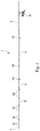
- Fig. 1 is an external view of a fishing rod 1 according to one embodiment of the invention, the fishing rod 1 having a fishing line guide 10 according to one embodiment of the present invention.
- the fishing rod 1 is a telescopic fishing rod having a butt rod section 3, a plurality of intermediate rod sections 5 (constituted by three ones in the example shown in Fig. 1 ), and a tip rod section 7.
- the intermediate rod sections 5 and the tip rod section 7 are housed in the hollow butt rod section 3.
- the butt rod section 3, the intermediate rod sections 5, and the tip rod section 7 each can be formed by using, for example, a prepreg sheet made of carbon fibers impregnated with a synthetic resin. Furthermore, the butt rod section 3, the intermediate rod sections 5, and the tip rod section 7 each have a tapered shape tapered toward the tip. On outer peripheral surfaces of the intermediate rod sections 5 and the tip rod section 7, there are provided a plurality of fishing line guides 10 that guide a fishing line released from a reel R, to the tip of the fishing rod 1.
- Fig. 2 is a front view of a fishing line guide 10 in one embodiment
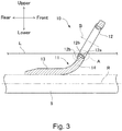
- Fig. 3 is a longitudinal sectional view of the fishing line guide 10.
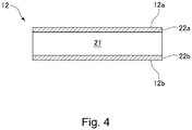
- Fig. 4 is a view schematically showing a cross section of a guide ring 12
- Fig. 5 is an enlarged longitudinal sectional view of a region in the vicinity of a lower end of the fishing line guide shown in Fig. 3 (a region enclosed by a dotted line A in Fig. 3 ).
- the fishing line guide 10 includes a guide body 11 and a guide ring 12 having an annular shape and mounted to the guide body 11.
- the guide body 11 includes a foot portion 13 mounted to any of a rod element 3, a rod element 5, and a rod element 7 and a plate-shaped ring retaining portion 14 connected to the foot portion 13.
- the following description is directed to an exemplary case where the fishing line guide 10 is mounted to the rod element 5.
- the foot portion 13 is an elongated plate-shaped or tongue-shaped member extending along an outer peripheral surface of the rod element 5.
- the foot portion 13 is wound on the rod element 5 by use of, for example, a winding thread made of nylon fibers.
- Fig. 2 illustratively shows a fishing line guide of a single-foot type having one foot portion used to mount the fishing line guide to a rod element
- a guide ring to which the present invention is applicable is not limited to the single-foot type.
- the present invention is also applicable to a guide ring of a double-foot type.
- a fishing line guide of the double foot type has a pair of foot portions extending from a ring retaining portion to a front side and a rear side, respectively, and this pair of foot portions is used to secure the fishing line guide to a rod element. Furthermore, the present invention is also applicable to both a stationary fishing line guide and a movable fishing line guide (which may be referred to as a free guide).
- the ring retaining portion 14 extends from an upper end of the foot portion 13.
- the ring retaining portion 14 is inclined upward from the rear toward the front of the rod element 5. That is, with the guide ring 10 mounted to the rod element 5, the ring retaining portion 14 leans toward the front of the rod element 5.
- the ring retaining portion 14 has a through hole formed therein, the through hole piercing the ring retaining portion 14 generally in a front-rear direction of the rod element 5. This through hole is defined by an inner peripheral surface 14a of the ring retaining portion 14. The guide ring 12 is fitted in this through hole.
- the ring retaining portion 14 is a generally flat plate-shaped member, a connection portion thereof connecting with the foot portion 13 is mildly curved as shown in Fig. 3 . That is, the ring retaining portion 14 includes a flat portion and a curved portion; the flat portion is generally flat and has the through hole formed therein, the guide ring 10 being fitted in the through hole, and the curved portion is mildly curved and is connected to the foot portion 13.
- the foot portion 13 and the ring retaining portion 14 can be integrally manufactured from a prepreg sheet.
- the first step is to press a plurality of prepreg sheets together and burn and hardening the pressed prepreg sheets, to thereby produce a shaped prepreg product.
- a frame having a shape corresponding to the foot portion 13 and the ring retaining portion 14 is cut out of the shaped prepreg product.
- the obtained frame is an integrated piece of the foot portion 13 and the ring retaining portion 14.
- the fishing line guide 10 can be manufactured by using any known technique other than the above.
- the fishing line guide 10 can be formed by injection molding using a metal or a synthetic resin.
- the annular guide ring 12 is fitted in the through hole of the ring retaining portion 14. As best shown in Fig. 3 , the guide ring 12 has a ring inner peripheral surface 12a extending annularly in a circumferential direction of the guide ring 12 and a ring outer peripheral surface 12b extending substantially parallel to the ring outer peripheral surface 12a.
- the guide ring 12 is made of, for example, ceramic, a metal, an alloy, or a composite thereof.
- Fig. 4 shows a guide ring 12 made of a Co-Ni base alloy subjected to a surface treatment.
- the guide ring 12 has a base material layer 21, a surface layer 22a, and a surface layer 22b.
- the surface later 22a is formed on a surface of the base material layer 21 near the inner peripheral surface 12a
- the surface layer 22b is formed on a surface of the base material layer 21 near the outer peripheral surface 12b.
- the surface layer 22a and the surface layer 22b may be referred to collectively as a surface layer 22.
- the surface layer 22b arranged near the outer peripheral surface 12b can be omitted.
- the base material layer 21 is made of, for example, a Co-Ni base alloy.
- the base material layer 21 is formed of, for example, an alloy containing Co, Ni, Cr, Mo, Fe, and inevitable impurities.
- the base material layer 21 may contain Mn, Ti, and/or Nb.
- the base material layer is constituted of, for example, 30 to 40 wt% Co, 27 to 37 wt% Ni, 12 to 25 wt% Cr, 5 to 10 wt% Mo, 3 wt% or less Fe, and a balance of inevitable impurities.
- the base material layer is made of, for example, SPRON 510 from Seiko Instruments Inc (SPRON is a registered trademark).
- the base material layer 21 has an Fe content of 3 wt% or less. In another embodiment of the present invention, the base material layer 21 has an Fe content of 2 wt% or less.
- the surface layer 22 is formed of, for example, chromium carbide (CrC), titanium carbide (TiC), or vanadium carbide (VC).
- CrC chromium carbide
- TiC titanium carbide
- VC vanadium carbide
- the surface layer 22 is formed on the surface of the base material layer 21 by, for example, subjecting the base material layer 21 to a carburizing process in accordance with an ordinary method so that a carburization layer is formed thereon and then subjecting the base material layer with the carburization layer formed thereon to a chromium impregnation-diffusion process (a chromizing process).
- the surface layer 22 is formed on the surface of the base material layer 21 by, for example, subjecting the base material layer 21 to the carburizing process in accordance with the ordinary method so that a carburization layer is formed thereon and next subjecting the base material layer with the carburization layer formed thereon to a titanium impregnation-diffusion process (a titanizing process).
- a titanium impregnation-diffusion process a titanizing process
- the surface layer 22 is formed on the surface of the base material layer 21 by, for example, subjecting the base material layer 21 to the carburizing process in accordance with the ordinary method so that a carburization layer is formed thereon and next subjecting the base material layer with the carburization layer formed thereon to a vanadium impregnation-diffusion process (a VC process).
- a VC process vanadium impregnation-diffusion process
- a surface of the guide ring 12 has a hardness as high as a Vickers hardness of about 1,300 Hv to 1,800 Hv (preferably, a Vickers hardness of about 1,600 Hv to 1,800 HV).
- the surface of the guide ring 12 has a hardness as high as a Vickers hardness of about 2,000 Hv to 3,000 Hv.
- the surface of the guide ring 12 has a hardness as high as a Vickers hardness of about 2,000 Hv to 3,000 Hv.
- the base material layer 21 is formed of an alloy having an Fe content of 3 wt% or less, and thus the guide ring 12 is extremely resistant to rust.
- the guide ring 12 has the ring inner peripheral surface 12a and the ring outer peripheral surface 12b.
- the ring inner peripheral surface 12a and the ring outer peripheral surface 12b are connected with each other at the rear end surface 12c and the front end surface 12d.
- the guide ring 12 has a top portion 12h that is most distant from the fishing rod 5 in a vertical direction V extending vertically with respect to the axial direction R of the fishing rod 5.
- the portion of the guide ring 12 located on the rear side of the top portion 12h may be referred to as a guide rear portion 12i, and the portion of the guide ring 12 located on the front side of the top portion 12h may be referred to as a guide front portion 12j.
- the thickness of the guide rear portion 12i is larger than that of the guide front portion 12j, as in Fig. 5 showing a sectional view of the guide ring 12 cut along a plane including the axial direction B of the guide ring 12.
- the thickness of the guide rear portion 12i is denoted by t1
- the thickness of the guide front portion 12j is denoted by t3.
- the guide rear portion 12i extends from the top portion 12h to the rear end surface 12c, and the thickness of the guide rear portion 12i of the guide ring 12 herein refers to the thickness of any portion of the guide rear portion 12i.
- the thickness t1 of the guide rear portion 12i decreases from the rear end toward the top portion 12h.
- the thickness t2 at the top portion 12h is smaller than the thickness t1 of the guide rear portion 12i.
- the guide front portion 12j extends from the top portion 12h to the front end surface 12d, and the thickness of the guide front portion 12j of the guide ring 12 herein refers to the thickness of any portion of the guide front portion 12j.
- the thickness t3 of the guide front portion 12j decreases from the top portion 12h toward the front end. Accordingly, the thickness t3 of the guide front portion 12j is smaller than the thickness t2 at the top portion 12h.
- the thickness of the guide rear portion 12i being larger than that of the guide front portion 12j means any of the following: (1) the thickness of any portion of the guide rear portion 12i is larger than that of any portion of the guide front portion 12j, (2) the thickness of the thickest portion of the guide rear portion 12i is larger than that of the thickest portion of the guide front portion 12j, and (3) the average thickness of the guide rear portion 12i is larger than the average thickness of the guide front portion 12j.
- the thickness of the guide rear portion 12i is larger than that of the guide front portion 12j, and therefore, the guide rear portion 12i, against which the fishing line collides at a high speed, can have a high impact resistance.
- the guide ring 12 contacts with the fishing line L in the vicinity of the top portion 12h of the ring inner peripheral surface 12a. Since the thickness t2 at the top portion 12h is larger than the thickness t3 of the guide front portion 12j, it is possible to inhibit the guide ring 12 from being broken due to wear.
- the guide ring 12 is curved into a convex form toward an inner peripheral side (toward the inner peripheral surface 12a) as viewed in a cross section cut along a plane including an axial direction B of the guide ring 12.
- the guide ring 12 is formed and disposed so that a rear edge portion 12e thereof extends along a rear surface 14c of the guide body 14.
- the guide ring 12 is formed and disposed so that a front surface 12f of the rear edge portion 12e thereof comes in contact with the rear surface 14c of the guide body 14.
- the guide ring 12 is more stably retained to the guide body 14.
- the guide ring 12 is formed and disposed so that a rear end surface 12c thereof is arranged on a rear side relative to the inner peripheral surface 14a of the guide body 14, while a front end surface 12d thereof comes in contact with the inner peripheral surface 14a of the guide body 14.
- the guide ring 12 makes contact at the end surface 12d thereof with the inner peripheral surface 14a of the guide body 14, so that a contact area between the guide ring 12 and an outer peripheral surface 14 of the through hole of the guide body 14 is decreased. Accordingly, when the guide ring 12 is fitted into the through hole of the guide body 14, a large stress is prevented from being exerted on the guide ring 12.
- the guide ring 12 is formed and disposed so that a front end portion 12g thereof is flush with a front surface 14d of the guide body 14. In another embodiment, the guide ring 12 is formed and disposed so that the front end portion 12g thereof is arranged at a position somewhat retracted to a rear side in the axial direction B relative to the front surface 14d. Thus, it is unlikely that the fishing line L gets caught on the guide ring 12 at the front of the fishing line guide 10.
- the guide ring 12 is formed and disposed so that a gap is formed between the outer peripheral surface 12b thereof and the inner peripheral surface 14a of the guide body 14. Any type of adhesive 15 may be applied in this gap. Thus, the guide ring 12 is more stably retained to the guide body 14.
- the guide ring 12 when the fishing line L is under a tension (for example, at the time of winding the fishing line L), the guide ring 12 makes contact at a top portion 12h thereof with the fishing line L, the top portion 12h being on an uppermost side of the inner peripheral surface 12a of the guide ring 12.
- the guide ring 12 is formed and disposed so that a tangential direction of the top portion 12 is substantially the same as an extending direction of the fishing line L (substantially the same as a longitudinal direction of the rod element 5).
- a friction force exerted on the fishing line L can be reduced.
- a guide ring base material is prepared.
- the above-mentioned SPRON 510 manufactured by Seiko Instruments Inc. can be used.
- the guide ring base material is worked into a shape of a thin plate having a thickness of 0.1 cm to 0.3 cm.
- the guide ring base material in the thin plate shape is heated to 900°C to 1,000°C so that the guide ring base material is softened. While being softened by this heating, the guide ring base material is worked, by pressing, from the thin plate shape into a ring shape shown in some of the figures such as Fig. 3 .
- the guide ring base material is worked such that its thickness is smaller from one end toward the other. More specifically, the guide ring base material is worked such that when the guide ring is mounted to the guide body, the thickness of the guide rear portion on the rear side relative to the top portion is larger than the thickness of the guide front portion on the front side relative to the top portion.
- the guide ring base material thus worked into the ring shape is subjected to a carburizing process in accordance with an ordinary method.
- the carburizing process is performed by generally following procedures described below. First, a carburizing box packed with a carburizing material primarily composed of charcoal is prepared. Next, the guide ring base material is buried in this carburizing box, which then is hermetically sealed. Next, the guide ring base material, together with the carburizing box, is heated at, for example, about 900°C to 1,200°C for a predetermined time. After being heated, the guide ring base material is cooled and then is taken out. Thus, a carburization layer is formed on a surface of the guide ring base material. In the present invention, liquid carburizing, gas carburizing, or vacuum carburizing may be used in place of the pack carburizing.
- the guide ring base material with the carburization layer formed thereon is subjected to a chromizing process in accordance with an ordinary method.
- the chromizing process is performed by generally following procedures described below. First, a process box packed with a preparation composed of a chromium powder, an aluminum oxide powder, and an ammonium chloride powder is prepared. Next, the guide ring base material with the carburization layer formed thereon is buried in this process box, which then is hermetically sealed. Next, the guide ring base material, together with the process box, is heated at, for example, about 900°C to 1,200°C for a predetermined time and then is cooled.
- a chromium carbide (CrC) layer having a thickness of about 10 ⁇ m to 30 ⁇ m is formed on the surface of the guide ring base material.
- CrC chromium carbide
- the guide ring is subjected to a predetermined cleaning process.
- the guide ring is polished using a barrel polisher so that the guide ring has predetermined dimensions and a predetermined surface roughness.
- a fishing line guide 110 according to another embodiment of the present invention shown in Fig. 6 is different from the fishing line guide 10 in terms of the shape of an inner peripheral surface of a ring retaining portion and the shape of a guide ring.
- an inner peripheral surface 114a of the fishing line guide 110 is formed so as to be inclined with respect to an axis B. Therefore, a through hole of a ring retaining portion 14, which is defined by the inner peripheral surface 114a, has a diameter decreasing from a rear side toward a front side of the axis B.
- the through hole of the ring retaining portion 14 of the fishing line guide 110 has a diameter increased on the rear side and decreased on the front side.
- a guide ring 112 is formed and disposed so that a front end surface 112d thereof comes in contact with the inner peripheral surface 114a in the vicinity of a front end thereof. Therefore, according to the embodiment shown in Fig. 6 , the guide ring 112 is fitted from the rear side toward the front side into the through hole of the ring retaining portion 14, and thus the guide ring 112 can be smoothly fitted into the through hole of the guide retaining portion 14.
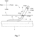
- a fishing line guide 210 according to another embodiment of the present invention shown in Fig. 7 is different from the fishing line guide 10 in terms of the shape of an inner peripheral surface of a ring retaining portion and the shape of a guide ring.
- an inner peripheral surface 214a of the fishing line guide 210 has an inclined portion 214a1 extending so as to be inclined with respect to an axis B and a small diameter portion 214a2 extending parallel to the axis B from a front end of the inclined portion 214a1.
- the small diameter portion 214a2 has a diameter smaller than that of the inclined portion 214a1.
- a guide ring 212 is formed and disposed so that a front end surface 212d thereof comes in contact with the small diameter portion 214a2. Therefore, according to the embodiment shown in Fig. 7 , the guide ring 212 is fitted from the rear side toward the front side into the through hole of the ring retaining portion 14, and thus the guide ring 212 can be smoothly fitted into the through hole of the guide retaining portion 14. Furthermore, according to the embodiment shown in Fig. 7 , the guide ring 212 can be stably retained by the small diameter portion 214a2.
Landscapes
- Life Sciences & Earth Sciences (AREA)
- Environmental Sciences (AREA)
- Marine Sciences & Fisheries (AREA)
- Animal Husbandry (AREA)
- Biodiversity & Conservation Biology (AREA)
- Engineering & Computer Science (AREA)
- General Engineering & Computer Science (AREA)
- Mechanical Engineering (AREA)
- Fishing Rods (AREA)
Applications Claiming Priority (2)
| Application Number | Priority Date | Filing Date | Title |
|---|---|---|---|
| JP2016038082 | 2016-02-29 | ||
| PCT/JP2016/081223 WO2017149832A1 (ja) | 2016-02-29 | 2016-10-21 | 釣糸ガイド、当該釣糸ガイドを備える釣竿、及び当該釣糸ガイド用のガイドリング |
Publications (3)
| Publication Number | Publication Date |
|---|---|
| EP3424318A1 true EP3424318A1 (de) | 2019-01-09 |
| EP3424318A4 EP3424318A4 (de) | 2019-10-23 |
| EP3424318B1 EP3424318B1 (de) | 2020-09-23 |
Family
ID=59743618
Family Applications (1)
| Application Number | Title | Priority Date | Filing Date |
|---|---|---|---|
| EP16892668.1A Active EP3424318B1 (de) | 2016-02-29 | 2016-10-21 | Angelschnurführung, angelrute mit der angelschnurführung |
Country Status (4)
| Country | Link |
|---|---|
| US (1) | US10897884B2 (de) |
| EP (1) | EP3424318B1 (de) |
| JP (1) | JP6817286B2 (de) |
| WO (1) | WO2017149832A1 (de) |
Families Citing this family (6)
| Publication number | Priority date | Publication date | Assignee | Title |
|---|---|---|---|---|
| US11076585B2 (en) * | 2016-01-27 | 2021-08-03 | Globeride, Inc. | Fishing line guide having high-hardness surface layer and fishing rod provided with said fishing line guide |
| JP6970006B2 (ja) * | 2017-12-22 | 2021-11-24 | 株式会社シマノ | 釣糸ガイド及び釣竿 |
| JP7506633B2 (ja) * | 2021-03-30 | 2024-06-26 | グローブライド株式会社 | 釣糸ガイド、該釣糸ガイドを備える釣竿 |
| JP7664093B2 (ja) * | 2021-06-09 | 2025-04-17 | 株式会社シマノ | 釣竿用ガイド |
| JP7664092B2 (ja) * | 2021-06-09 | 2025-04-17 | 株式会社シマノ | 釣竿用ガイド |
| FR3142651B1 (fr) | 2022-12-02 | 2025-04-25 | Charuel Loic | Procédé de fabrication d'un élément de guidage d'une ligne de canne à pêche |
Family Cites Families (17)
| Publication number | Priority date | Publication date | Assignee | Title |
|---|---|---|---|---|
| US2502845A (en) * | 1947-07-21 | 1950-04-04 | William M Hoffman | Line guide element for fishing rods and the like |
| US3171228A (en) * | 1959-10-12 | 1965-03-02 | Joseph A Cwik | Rod guides and tips |
| JP2955504B2 (ja) * | 1995-11-13 | 1999-10-04 | 富士工業株式会社 | 釣竿用トップガイド |
| JP2916431B2 (ja) * | 1996-11-12 | 1999-07-05 | 富士工業株式会社 | 釣竿用導糸環 |
| TW371256B (en) | 1996-11-12 | 1999-10-01 | Fuji Industries Co Ltd | Line guide for fishing rod |
| JP2916429B2 (ja) | 1996-11-12 | 1999-07-05 | 富士工業株式会社 | 釣竿用導糸環 |
| JP3093986B2 (ja) * | 1997-01-28 | 2000-10-03 | 富士工業株式会社 | 釣竿用トップガイド |
| JPH11155429A (ja) | 1997-11-29 | 1999-06-15 | Fuji Kogyo Kk | ガイドリング |
| JP2003274810A (ja) | 2002-03-27 | 2003-09-30 | Daiwa Seiko Inc | 外ガイドを有する釣竿 |
| KR101682242B1 (ko) | 2009-03-30 | 2016-12-05 | 글로브라이드 가부시키가이샤 | 낚싯줄 가이드의 제조 방법 |
| JP5647847B2 (ja) * | 2010-09-30 | 2015-01-07 | グローブライド株式会社 | 釣糸ガイド |
| JP5794773B2 (ja) | 2010-11-05 | 2015-10-14 | 株式会社シマノ | 釣り糸用ガイド及び釣り竿 |
| JP5606295B2 (ja) | 2010-11-26 | 2014-10-15 | 株式会社シマノ | 釣り糸用ガイド及び釣り竿 |
| EP2742800B1 (de) | 2011-11-15 | 2017-04-05 | Globeride, Inc. | Angelschnurführung und angelrute damit |
| WO2014119522A1 (ja) | 2013-01-31 | 2014-08-07 | 京セラ株式会社 | 釣り糸用ガイド部材およびこれを備える釣り糸用ガイドならびに釣り竿 |
| JP6157937B2 (ja) | 2013-06-07 | 2017-07-05 | 株式会社東芝 | 弁装置およびその製造方法 |
| JP6386710B2 (ja) | 2013-09-30 | 2018-09-05 | グローブライド株式会社 | 釣糸ガイド |
-
2016
- 2016-10-21 JP JP2018502513A patent/JP6817286B2/ja active Active
- 2016-10-21 WO PCT/JP2016/081223 patent/WO2017149832A1/ja not_active Ceased
- 2016-10-21 US US16/080,526 patent/US10897884B2/en active Active
- 2016-10-21 EP EP16892668.1A patent/EP3424318B1/de active Active
Also Published As
| Publication number | Publication date |
|---|---|
| JP6817286B2 (ja) | 2021-01-20 |
| WO2017149832A1 (ja) | 2017-09-08 |
| EP3424318B1 (de) | 2020-09-23 |
| JPWO2017149832A1 (ja) | 2019-01-10 |
| US20190008129A1 (en) | 2019-01-10 |
| US10897884B2 (en) | 2021-01-26 |
| EP3424318A4 (de) | 2019-10-23 |
Similar Documents
| Publication | Publication Date | Title |
|---|---|---|
| EP3409111B1 (de) | Angelschnurführung mit hochharter oberflächenschicht und mit solch einer angelführungsschnur ausgestattete angelrute | |
| EP3424318B1 (de) | Angelschnurführung, angelrute mit der angelschnurführung | |
| JP7063838B2 (ja) | 釣糸ガイド及び当該釣糸ガイドを備える釣竿 | |
| KR102831973B1 (ko) | 낚싯줄 가이드의 가이드 프레임 및 낚싯줄 가이드 및 낚싯대 | |
| US20250302021A1 (en) | Fishing rod | |
| JP5460544B2 (ja) | 釣糸ガイド及び釣竿 | |
| JP5634112B2 (ja) | 釣り糸用ガイド及び釣り竿 | |
| JP5647847B2 (ja) | 釣糸ガイド | |
| JP2010233529A (ja) | 釣り糸ガイド及び釣り竿 | |
| JP5626762B2 (ja) | 釣り糸用ガイド及び釣り竿 | |
| EP2845479B1 (de) | Angelschnurführung und Angelrute | |
| JP5478350B2 (ja) | 釣り糸ガイド | |
| JP2002262725A (ja) | 釣糸案内ガイドの釣糸案内体及び釣糸案内ガイド | |
| JP2007244396A (ja) | ルアーロッド | |
| US20260000060A1 (en) | Fishing line guide and fishing rod | |
| TWI773314B (zh) | 釣線導線器及具備該釣線導線器的釣竿 | |
| JP6621392B2 (ja) | 釣糸ガイド及び当該釣糸ガイドを備える釣竿 | |
| JP4040771B2 (ja) | 釣竿 | |
| CN113273551A (zh) | 钓竿 | |
| JP2005210986A (ja) | 穂先竿とその製造方法 |
Legal Events
| Date | Code | Title | Description |
|---|---|---|---|
| STAA | Information on the status of an ep patent application or granted ep patent |
Free format text: STATUS: THE INTERNATIONAL PUBLICATION HAS BEEN MADE |
|
| PUAI | Public reference made under article 153(3) epc to a published international application that has entered the european phase |
Free format text: ORIGINAL CODE: 0009012 |
|
| STAA | Information on the status of an ep patent application or granted ep patent |
Free format text: STATUS: REQUEST FOR EXAMINATION WAS MADE |
|
| 17P | Request for examination filed |
Effective date: 20180926 |
|
| AK | Designated contracting states |
Kind code of ref document: A1 Designated state(s): AL AT BE BG CH CY CZ DE DK EE ES FI FR GB GR HR HU IE IS IT LI LT LU LV MC MK MT NL NO PL PT RO RS SE SI SK SM TR |
|
| AX | Request for extension of the european patent |
Extension state: BA ME |
|
| DAV | Request for validation of the european patent (deleted) | ||
| DAX | Request for extension of the european patent (deleted) | ||
| A4 | Supplementary search report drawn up and despatched |
Effective date: 20190919 |
|
| RIC1 | Information provided on ipc code assigned before grant |
Ipc: A01K 87/04 20060101AFI20190914BHEP |
|
| RIN1 | Information on inventor provided before grant (corrected) |
Inventor name: AKIBA, MASARU Inventor name: WATANABE, MASAYUKI |
|
| GRAP | Despatch of communication of intention to grant a patent |
Free format text: ORIGINAL CODE: EPIDOSNIGR1 |
|
| STAA | Information on the status of an ep patent application or granted ep patent |
Free format text: STATUS: GRANT OF PATENT IS INTENDED |
|
| INTG | Intention to grant announced |
Effective date: 20200416 |
|
| GRAS | Grant fee paid |
Free format text: ORIGINAL CODE: EPIDOSNIGR3 |
|
| GRAA | (expected) grant |
Free format text: ORIGINAL CODE: 0009210 |
|
| STAA | Information on the status of an ep patent application or granted ep patent |
Free format text: STATUS: THE PATENT HAS BEEN GRANTED |
|
| AK | Designated contracting states |
Kind code of ref document: B1 Designated state(s): AL AT BE BG CH CY CZ DE DK EE ES FI FR GB GR HR HU IE IS IT LI LT LU LV MC MK MT NL NO PL PT RO RS SE SI SK SM TR |
|
| REG | Reference to a national code |
Ref country code: GB Ref legal event code: FG4D |
|
| REG | Reference to a national code |
Ref country code: CH Ref legal event code: EP |
|
| REG | Reference to a national code |
Ref country code: DE Ref legal event code: R096 Ref document number: 602016044767 Country of ref document: DE |
|
| REG | Reference to a national code |
Ref country code: IE Ref legal event code: FG4D |
|
| REG | Reference to a national code |
Ref country code: AT Ref legal event code: REF Ref document number: 1315438 Country of ref document: AT Kind code of ref document: T Effective date: 20201015 |
|
| PG25 | Lapsed in a contracting state [announced via postgrant information from national office to epo] |
Ref country code: HR Free format text: LAPSE BECAUSE OF FAILURE TO SUBMIT A TRANSLATION OF THE DESCRIPTION OR TO PAY THE FEE WITHIN THE PRESCRIBED TIME-LIMIT Effective date: 20200923 Ref country code: BG Free format text: LAPSE BECAUSE OF FAILURE TO SUBMIT A TRANSLATION OF THE DESCRIPTION OR TO PAY THE FEE WITHIN THE PRESCRIBED TIME-LIMIT Effective date: 20201223 Ref country code: GR Free format text: LAPSE BECAUSE OF FAILURE TO SUBMIT A TRANSLATION OF THE DESCRIPTION OR TO PAY THE FEE WITHIN THE PRESCRIBED TIME-LIMIT Effective date: 20201224 Ref country code: NO Free format text: LAPSE BECAUSE OF FAILURE TO SUBMIT A TRANSLATION OF THE DESCRIPTION OR TO PAY THE FEE WITHIN THE PRESCRIBED TIME-LIMIT Effective date: 20201223 Ref country code: SE Free format text: LAPSE BECAUSE OF FAILURE TO SUBMIT A TRANSLATION OF THE DESCRIPTION OR TO PAY THE FEE WITHIN THE PRESCRIBED TIME-LIMIT Effective date: 20200923 Ref country code: FI Free format text: LAPSE BECAUSE OF FAILURE TO SUBMIT A TRANSLATION OF THE DESCRIPTION OR TO PAY THE FEE WITHIN THE PRESCRIBED TIME-LIMIT Effective date: 20200923 |
|
| REG | Reference to a national code |
Ref country code: AT Ref legal event code: MK05 Ref document number: 1315438 Country of ref document: AT Kind code of ref document: T Effective date: 20200923 |
|
| PG25 | Lapsed in a contracting state [announced via postgrant information from national office to epo] |
Ref country code: LV Free format text: LAPSE BECAUSE OF FAILURE TO SUBMIT A TRANSLATION OF THE DESCRIPTION OR TO PAY THE FEE WITHIN THE PRESCRIBED TIME-LIMIT Effective date: 20200923 Ref country code: RS Free format text: LAPSE BECAUSE OF FAILURE TO SUBMIT A TRANSLATION OF THE DESCRIPTION OR TO PAY THE FEE WITHIN THE PRESCRIBED TIME-LIMIT Effective date: 20200923 |
|
| REG | Reference to a national code |
Ref country code: NL Ref legal event code: MP Effective date: 20200923 |
|
| REG | Reference to a national code |
Ref country code: LT Ref legal event code: MG4D |
|
| PG25 | Lapsed in a contracting state [announced via postgrant information from national office to epo] |
Ref country code: SM Free format text: LAPSE BECAUSE OF FAILURE TO SUBMIT A TRANSLATION OF THE DESCRIPTION OR TO PAY THE FEE WITHIN THE PRESCRIBED TIME-LIMIT Effective date: 20200923 Ref country code: EE Free format text: LAPSE BECAUSE OF FAILURE TO SUBMIT A TRANSLATION OF THE DESCRIPTION OR TO PAY THE FEE WITHIN THE PRESCRIBED TIME-LIMIT Effective date: 20200923 Ref country code: RO Free format text: LAPSE BECAUSE OF FAILURE TO SUBMIT A TRANSLATION OF THE DESCRIPTION OR TO PAY THE FEE WITHIN THE PRESCRIBED TIME-LIMIT Effective date: 20200923 Ref country code: PT Free format text: LAPSE BECAUSE OF FAILURE TO SUBMIT A TRANSLATION OF THE DESCRIPTION OR TO PAY THE FEE WITHIN THE PRESCRIBED TIME-LIMIT Effective date: 20210125 Ref country code: CZ Free format text: LAPSE BECAUSE OF FAILURE TO SUBMIT A TRANSLATION OF THE DESCRIPTION OR TO PAY THE FEE WITHIN THE PRESCRIBED TIME-LIMIT Effective date: 20200923 Ref country code: LT Free format text: LAPSE BECAUSE OF FAILURE TO SUBMIT A TRANSLATION OF THE DESCRIPTION OR TO PAY THE FEE WITHIN THE PRESCRIBED TIME-LIMIT Effective date: 20200923 |
|
| REG | Reference to a national code |
Ref country code: DE Ref legal event code: R119 Ref document number: 602016044767 Country of ref document: DE |
|
| PG25 | Lapsed in a contracting state [announced via postgrant information from national office to epo] |
Ref country code: AT Free format text: LAPSE BECAUSE OF FAILURE TO SUBMIT A TRANSLATION OF THE DESCRIPTION OR TO PAY THE FEE WITHIN THE PRESCRIBED TIME-LIMIT Effective date: 20200923 Ref country code: AL Free format text: LAPSE BECAUSE OF FAILURE TO SUBMIT A TRANSLATION OF THE DESCRIPTION OR TO PAY THE FEE WITHIN THE PRESCRIBED TIME-LIMIT Effective date: 20200923 Ref country code: ES Free format text: LAPSE BECAUSE OF FAILURE TO SUBMIT A TRANSLATION OF THE DESCRIPTION OR TO PAY THE FEE WITHIN THE PRESCRIBED TIME-LIMIT Effective date: 20200923 Ref country code: IS Free format text: LAPSE BECAUSE OF FAILURE TO SUBMIT A TRANSLATION OF THE DESCRIPTION OR TO PAY THE FEE WITHIN THE PRESCRIBED TIME-LIMIT Effective date: 20210123 Ref country code: PL Free format text: LAPSE BECAUSE OF FAILURE TO SUBMIT A TRANSLATION OF THE DESCRIPTION OR TO PAY THE FEE WITHIN THE PRESCRIBED TIME-LIMIT Effective date: 20200923 |
|
| REG | Reference to a national code |
Ref country code: CH Ref legal event code: PL |
|
| PG25 | Lapsed in a contracting state [announced via postgrant information from national office to epo] |
Ref country code: LU Free format text: LAPSE BECAUSE OF NON-PAYMENT OF DUE FEES Effective date: 20201021 Ref country code: SK Free format text: LAPSE BECAUSE OF FAILURE TO SUBMIT A TRANSLATION OF THE DESCRIPTION OR TO PAY THE FEE WITHIN THE PRESCRIBED TIME-LIMIT Effective date: 20200923 Ref country code: MC Free format text: LAPSE BECAUSE OF FAILURE TO SUBMIT A TRANSLATION OF THE DESCRIPTION OR TO PAY THE FEE WITHIN THE PRESCRIBED TIME-LIMIT Effective date: 20200923 |
|
| REG | Reference to a national code |
Ref country code: BE Ref legal event code: MM Effective date: 20201031 |
|
| PG25 | Lapsed in a contracting state [announced via postgrant information from national office to epo] |
Ref country code: DE Free format text: LAPSE BECAUSE OF NON-PAYMENT OF DUE FEES Effective date: 20210501 |
|
| PLBE | No opposition filed within time limit |
Free format text: ORIGINAL CODE: 0009261 |
|
| STAA | Information on the status of an ep patent application or granted ep patent |
Free format text: STATUS: NO OPPOSITION FILED WITHIN TIME LIMIT |
|
| PG25 | Lapsed in a contracting state [announced via postgrant information from national office to epo] |
Ref country code: BE Free format text: LAPSE BECAUSE OF NON-PAYMENT OF DUE FEES Effective date: 20201031 Ref country code: CH Free format text: LAPSE BECAUSE OF NON-PAYMENT OF DUE FEES Effective date: 20201031 Ref country code: SI Free format text: LAPSE BECAUSE OF FAILURE TO SUBMIT A TRANSLATION OF THE DESCRIPTION OR TO PAY THE FEE WITHIN THE PRESCRIBED TIME-LIMIT Effective date: 20200923 Ref country code: DK Free format text: LAPSE BECAUSE OF FAILURE TO SUBMIT A TRANSLATION OF THE DESCRIPTION OR TO PAY THE FEE WITHIN THE PRESCRIBED TIME-LIMIT Effective date: 20200923 Ref country code: LI Free format text: LAPSE BECAUSE OF NON-PAYMENT OF DUE FEES Effective date: 20201031 |
|
| 26N | No opposition filed |
Effective date: 20210624 |
|
| PG25 | Lapsed in a contracting state [announced via postgrant information from national office to epo] |
Ref country code: IT Free format text: LAPSE BECAUSE OF FAILURE TO SUBMIT A TRANSLATION OF THE DESCRIPTION OR TO PAY THE FEE WITHIN THE PRESCRIBED TIME-LIMIT Effective date: 20200923 Ref country code: IE Free format text: LAPSE BECAUSE OF NON-PAYMENT OF DUE FEES Effective date: 20201021 |
|
| PG25 | Lapsed in a contracting state [announced via postgrant information from national office to epo] |
Ref country code: TR Free format text: LAPSE BECAUSE OF FAILURE TO SUBMIT A TRANSLATION OF THE DESCRIPTION OR TO PAY THE FEE WITHIN THE PRESCRIBED TIME-LIMIT Effective date: 20200923 Ref country code: MT Free format text: LAPSE BECAUSE OF FAILURE TO SUBMIT A TRANSLATION OF THE DESCRIPTION OR TO PAY THE FEE WITHIN THE PRESCRIBED TIME-LIMIT Effective date: 20200923 Ref country code: CY Free format text: LAPSE BECAUSE OF FAILURE TO SUBMIT A TRANSLATION OF THE DESCRIPTION OR TO PAY THE FEE WITHIN THE PRESCRIBED TIME-LIMIT Effective date: 20200923 |
|
| PG25 | Lapsed in a contracting state [announced via postgrant information from national office to epo] |
Ref country code: MK Free format text: LAPSE BECAUSE OF FAILURE TO SUBMIT A TRANSLATION OF THE DESCRIPTION OR TO PAY THE FEE WITHIN THE PRESCRIBED TIME-LIMIT Effective date: 20200923 |
|
| P01 | Opt-out of the competence of the unified patent court (upc) registered |
Effective date: 20230512 |
|
| PG25 | Lapsed in a contracting state [announced via postgrant information from national office to epo] |
Ref country code: NL Free format text: LAPSE BECAUSE OF NON-PAYMENT OF DUE FEES Effective date: 20200923 |
|
| PGFP | Annual fee paid to national office [announced via postgrant information from national office to epo] |
Ref country code: GB Payment date: 20250828 Year of fee payment: 10 |
|
| PGFP | Annual fee paid to national office [announced via postgrant information from national office to epo] |
Ref country code: FR Payment date: 20250908 Year of fee payment: 10 |