EP3421284A1 - Anzeigevorrichtung für ein kraftfahrzeug, verfahren zur herstellung einer anzeigevorrichtung für ein kraftfahrzeug - Google Patents
Anzeigevorrichtung für ein kraftfahrzeug, verfahren zur herstellung einer anzeigevorrichtung für ein kraftfahrzeug Download PDFInfo
- Publication number
- EP3421284A1 EP3421284A1 EP18173935.0A EP18173935A EP3421284A1 EP 3421284 A1 EP3421284 A1 EP 3421284A1 EP 18173935 A EP18173935 A EP 18173935A EP 3421284 A1 EP3421284 A1 EP 3421284A1
- Authority
- EP
- European Patent Office
- Prior art keywords
- display
- display device
- displays
- holding frame
- motor vehicle
- Prior art date
- Legal status (The legal status is an assumption and is not a legal conclusion. Google has not performed a legal analysis and makes no representation as to the accuracy of the status listed.)
- Granted
Links
Images


Classifications
-
- B—PERFORMING OPERATIONS; TRANSPORTING
- B60—VEHICLES IN GENERAL
- B60K—ARRANGEMENT OR MOUNTING OF PROPULSION UNITS OR OF TRANSMISSIONS IN VEHICLES; ARRANGEMENT OR MOUNTING OF PLURAL DIVERSE PRIME-MOVERS IN VEHICLES; AUXILIARY DRIVES FOR VEHICLES; INSTRUMENTATION OR DASHBOARDS FOR VEHICLES; ARRANGEMENTS IN CONNECTION WITH COOLING, AIR INTAKE, GAS EXHAUST OR FUEL SUPPLY OF PROPULSION UNITS IN VEHICLES
- B60K35/00—Instruments specially adapted for vehicles; Arrangement of instruments in or on vehicles
- B60K35/20—Output arrangements, i.e. from vehicle to user, associated with vehicle functions or specially adapted therefor
- B60K35/21—Output arrangements, i.e. from vehicle to user, associated with vehicle functions or specially adapted therefor using visual output, e.g. blinking lights or matrix displays
- B60K35/22—Display screens
-
- B—PERFORMING OPERATIONS; TRANSPORTING
- B60—VEHICLES IN GENERAL
- B60R—VEHICLES, VEHICLE FITTINGS, OR VEHICLE PARTS, NOT OTHERWISE PROVIDED FOR
- B60R11/00—Arrangements for holding or mounting articles, not otherwise provided for
- B60R11/02—Arrangements for holding or mounting articles, not otherwise provided for for radio sets, television sets, telephones, or the like; Arrangement of controls thereof
- B60R11/0229—Arrangements for holding or mounting articles, not otherwise provided for for radio sets, television sets, telephones, or the like; Arrangement of controls thereof for displays, e.g. cathodic tubes
- B60R11/0235—Arrangements for holding or mounting articles, not otherwise provided for for radio sets, television sets, telephones, or the like; Arrangement of controls thereof for displays, e.g. cathodic tubes of flat type, e.g. LCD
-
- B—PERFORMING OPERATIONS; TRANSPORTING
- B60—VEHICLES IN GENERAL
- B60K—ARRANGEMENT OR MOUNTING OF PROPULSION UNITS OR OF TRANSMISSIONS IN VEHICLES; ARRANGEMENT OR MOUNTING OF PLURAL DIVERSE PRIME-MOVERS IN VEHICLES; AUXILIARY DRIVES FOR VEHICLES; INSTRUMENTATION OR DASHBOARDS FOR VEHICLES; ARRANGEMENTS IN CONNECTION WITH COOLING, AIR INTAKE, GAS EXHAUST OR FUEL SUPPLY OF PROPULSION UNITS IN VEHICLES
- B60K35/00—Instruments specially adapted for vehicles; Arrangement of instruments in or on vehicles
- B60K35/20—Output arrangements, i.e. from vehicle to user, associated with vehicle functions or specially adapted therefor
- B60K35/28—Output arrangements, i.e. from vehicle to user, associated with vehicle functions or specially adapted therefor characterised by the type of the output information, e.g. video entertainment or vehicle dynamics information; characterised by the purpose of the output information, e.g. for attracting the attention of the driver
-
- B—PERFORMING OPERATIONS; TRANSPORTING
- B60—VEHICLES IN GENERAL
- B60K—ARRANGEMENT OR MOUNTING OF PROPULSION UNITS OR OF TRANSMISSIONS IN VEHICLES; ARRANGEMENT OR MOUNTING OF PLURAL DIVERSE PRIME-MOVERS IN VEHICLES; AUXILIARY DRIVES FOR VEHICLES; INSTRUMENTATION OR DASHBOARDS FOR VEHICLES; ARRANGEMENTS IN CONNECTION WITH COOLING, AIR INTAKE, GAS EXHAUST OR FUEL SUPPLY OF PROPULSION UNITS IN VEHICLES
- B60K35/00—Instruments specially adapted for vehicles; Arrangement of instruments in or on vehicles
- B60K35/50—Instruments characterised by their means of attachment to or integration in the vehicle
-
- B—PERFORMING OPERATIONS; TRANSPORTING
- B60—VEHICLES IN GENERAL
- B60K—ARRANGEMENT OR MOUNTING OF PROPULSION UNITS OR OF TRANSMISSIONS IN VEHICLES; ARRANGEMENT OR MOUNTING OF PLURAL DIVERSE PRIME-MOVERS IN VEHICLES; AUXILIARY DRIVES FOR VEHICLES; INSTRUMENTATION OR DASHBOARDS FOR VEHICLES; ARRANGEMENTS IN CONNECTION WITH COOLING, AIR INTAKE, GAS EXHAUST OR FUEL SUPPLY OF PROPULSION UNITS IN VEHICLES
- B60K35/00—Instruments specially adapted for vehicles; Arrangement of instruments in or on vehicles
- B60K35/60—Instruments characterised by their location or relative disposition in or on vehicles
-
- B—PERFORMING OPERATIONS; TRANSPORTING
- B60—VEHICLES IN GENERAL
- B60K—ARRANGEMENT OR MOUNTING OF PROPULSION UNITS OR OF TRANSMISSIONS IN VEHICLES; ARRANGEMENT OR MOUNTING OF PLURAL DIVERSE PRIME-MOVERS IN VEHICLES; AUXILIARY DRIVES FOR VEHICLES; INSTRUMENTATION OR DASHBOARDS FOR VEHICLES; ARRANGEMENTS IN CONNECTION WITH COOLING, AIR INTAKE, GAS EXHAUST OR FUEL SUPPLY OF PROPULSION UNITS IN VEHICLES
- B60K35/00—Instruments specially adapted for vehicles; Arrangement of instruments in or on vehicles
- B60K35/80—Arrangements for controlling instruments
- B60K35/81—Arrangements for controlling instruments for controlling displays
-
- B—PERFORMING OPERATIONS; TRANSPORTING
- B60—VEHICLES IN GENERAL
- B60K—ARRANGEMENT OR MOUNTING OF PROPULSION UNITS OR OF TRANSMISSIONS IN VEHICLES; ARRANGEMENT OR MOUNTING OF PLURAL DIVERSE PRIME-MOVERS IN VEHICLES; AUXILIARY DRIVES FOR VEHICLES; INSTRUMENTATION OR DASHBOARDS FOR VEHICLES; ARRANGEMENTS IN CONNECTION WITH COOLING, AIR INTAKE, GAS EXHAUST OR FUEL SUPPLY OF PROPULSION UNITS IN VEHICLES
- B60K37/00—Dashboards
- B60K37/20—Dashboard panels
-
- F—MECHANICAL ENGINEERING; LIGHTING; HEATING; WEAPONS; BLASTING
- F16—ENGINEERING ELEMENTS AND UNITS; GENERAL MEASURES FOR PRODUCING AND MAINTAINING EFFECTIVE FUNCTIONING OF MACHINES OR INSTALLATIONS; THERMAL INSULATION IN GENERAL
- F16B—DEVICES FOR FASTENING OR SECURING CONSTRUCTIONAL ELEMENTS OR MACHINE PARTS TOGETHER, e.g. NAILS, BOLTS, CIRCLIPS, CLAMPS, CLIPS OR WEDGES; JOINTS OR JOINTING
- F16B2/00—Friction-grip releasable fastenings
- F16B2/02—Clamps, i.e. with gripping action effected by positive means other than the inherent resistance to deformation of the material of the fastening
- F16B2/06—Clamps, i.e. with gripping action effected by positive means other than the inherent resistance to deformation of the material of the fastening external, i.e. with contracting action
- F16B2/12—Clamps, i.e. with gripping action effected by positive means other than the inherent resistance to deformation of the material of the fastening external, i.e. with contracting action using sliding jaws
-
- F—MECHANICAL ENGINEERING; LIGHTING; HEATING; WEAPONS; BLASTING
- F16—ENGINEERING ELEMENTS AND UNITS; GENERAL MEASURES FOR PRODUCING AND MAINTAINING EFFECTIVE FUNCTIONING OF MACHINES OR INSTALLATIONS; THERMAL INSULATION IN GENERAL
- F16B—DEVICES FOR FASTENING OR SECURING CONSTRUCTIONAL ELEMENTS OR MACHINE PARTS TOGETHER, e.g. NAILS, BOLTS, CIRCLIPS, CLAMPS, CLIPS OR WEDGES; JOINTS OR JOINTING
- F16B5/00—Joining sheets or plates, e.g. panels, to one another or to strips or bars parallel to them
- F16B5/02—Joining sheets or plates, e.g. panels, to one another or to strips or bars parallel to them by means of fastening members using screw-thread
-
- G—PHYSICS
- G06—COMPUTING OR CALCULATING; COUNTING
- G06F—ELECTRIC DIGITAL DATA PROCESSING
- G06F3/00—Input arrangements for transferring data to be processed into a form capable of being handled by the computer; Output arrangements for transferring data from processing unit to output unit, e.g. interface arrangements
- G06F3/14—Digital output to display device ; Cooperation and interconnection of the display device with other functional units
- G06F3/1423—Digital output to display device ; Cooperation and interconnection of the display device with other functional units controlling a plurality of local displays, e.g. CRT and flat panel display
- G06F3/1446—Digital output to display device ; Cooperation and interconnection of the display device with other functional units controlling a plurality of local displays, e.g. CRT and flat panel display display composed of modules, e.g. video walls
-
- G—PHYSICS
- G09—EDUCATION; CRYPTOGRAPHY; DISPLAY; ADVERTISING; SEALS
- G09F—DISPLAYING; ADVERTISING; SIGNS; LABELS OR NAME-PLATES; SEALS
- G09F9/00—Indicating arrangements for variable information in which the information is built-up on a support by selection or combination of individual elements
- G09F9/30—Indicating arrangements for variable information in which the information is built-up on a support by selection or combination of individual elements in which the desired character or characters are formed by combining individual elements
- G09F9/302—Indicating arrangements for variable information in which the information is built-up on a support by selection or combination of individual elements in which the desired character or characters are formed by combining individual elements characterised by the form or geometrical disposition of the individual elements
-
- G—PHYSICS
- G09—EDUCATION; CRYPTOGRAPHY; DISPLAY; ADVERTISING; SEALS
- G09F—DISPLAYING; ADVERTISING; SIGNS; LABELS OR NAME-PLATES; SEALS
- G09F9/00—Indicating arrangements for variable information in which the information is built-up on a support by selection or combination of individual elements
- G09F9/30—Indicating arrangements for variable information in which the information is built-up on a support by selection or combination of individual elements in which the desired character or characters are formed by combining individual elements
- G09F9/302—Indicating arrangements for variable information in which the information is built-up on a support by selection or combination of individual elements in which the desired character or characters are formed by combining individual elements characterised by the form or geometrical disposition of the individual elements
- G09F9/3026—Video wall, i.e. stackable semiconductor matrix display modules
-
- H—ELECTRICITY
- H05—ELECTRIC TECHNIQUES NOT OTHERWISE PROVIDED FOR
- H05K—PRINTED CIRCUITS; CASINGS OR CONSTRUCTIONAL DETAILS OF ELECTRIC APPARATUS; MANUFACTURE OF ASSEMBLAGES OF ELECTRICAL COMPONENTS
- H05K7/00—Constructional details common to different types of electric apparatus
- H05K7/18—Construction of rack or frame
-
- B—PERFORMING OPERATIONS; TRANSPORTING
- B60—VEHICLES IN GENERAL
- B60K—ARRANGEMENT OR MOUNTING OF PROPULSION UNITS OR OF TRANSMISSIONS IN VEHICLES; ARRANGEMENT OR MOUNTING OF PLURAL DIVERSE PRIME-MOVERS IN VEHICLES; AUXILIARY DRIVES FOR VEHICLES; INSTRUMENTATION OR DASHBOARDS FOR VEHICLES; ARRANGEMENTS IN CONNECTION WITH COOLING, AIR INTAKE, GAS EXHAUST OR FUEL SUPPLY OF PROPULSION UNITS IN VEHICLES
- B60K2360/00—Indexing scheme associated with groups B60K35/00 or B60K37/00 relating to details of instruments or dashboards
- B60K2360/77—Instrument locations other than the dashboard
- B60K2360/774—Instrument locations other than the dashboard on or in the centre console
-
- B—PERFORMING OPERATIONS; TRANSPORTING
- B60—VEHICLES IN GENERAL
- B60K—ARRANGEMENT OR MOUNTING OF PROPULSION UNITS OR OF TRANSMISSIONS IN VEHICLES; ARRANGEMENT OR MOUNTING OF PLURAL DIVERSE PRIME-MOVERS IN VEHICLES; AUXILIARY DRIVES FOR VEHICLES; INSTRUMENTATION OR DASHBOARDS FOR VEHICLES; ARRANGEMENTS IN CONNECTION WITH COOLING, AIR INTAKE, GAS EXHAUST OR FUEL SUPPLY OF PROPULSION UNITS IN VEHICLES
- B60K2360/00—Indexing scheme associated with groups B60K35/00 or B60K37/00 relating to details of instruments or dashboards
- B60K2360/816—Fastening of displays or touch screens
-
- B—PERFORMING OPERATIONS; TRANSPORTING
- B60—VEHICLES IN GENERAL
- B60K—ARRANGEMENT OR MOUNTING OF PROPULSION UNITS OR OF TRANSMISSIONS IN VEHICLES; ARRANGEMENT OR MOUNTING OF PLURAL DIVERSE PRIME-MOVERS IN VEHICLES; AUXILIARY DRIVES FOR VEHICLES; INSTRUMENTATION OR DASHBOARDS FOR VEHICLES; ARRANGEMENTS IN CONNECTION WITH COOLING, AIR INTAKE, GAS EXHAUST OR FUEL SUPPLY OF PROPULSION UNITS IN VEHICLES
- B60K2360/00—Indexing scheme associated with groups B60K35/00 or B60K37/00 relating to details of instruments or dashboards
- B60K2360/822—Adjustment of instruments during mounting
-
- B—PERFORMING OPERATIONS; TRANSPORTING
- B60—VEHICLES IN GENERAL
- B60R—VEHICLES, VEHICLE FITTINGS, OR VEHICLE PARTS, NOT OTHERWISE PROVIDED FOR
- B60R11/00—Arrangements for holding or mounting articles, not otherwise provided for
- B60R2011/0042—Arrangements for holding or mounting articles, not otherwise provided for characterised by mounting means
- B60R2011/0049—Arrangements for holding or mounting articles, not otherwise provided for characterised by mounting means for non integrated articles
- B60R2011/0064—Connection with the article
- B60R2011/0066—Connection with the article using screws, bolts, rivets or the like
-
- B—PERFORMING OPERATIONS; TRANSPORTING
- B60—VEHICLES IN GENERAL
- B60Y—INDEXING SCHEME RELATING TO ASPECTS CROSS-CUTTING VEHICLE TECHNOLOGY
- B60Y2304/00—Optimising design; Manufacturing; Testing
- B60Y2304/07—Facilitating assembling or mounting
-
- F—MECHANICAL ENGINEERING; LIGHTING; HEATING; WEAPONS; BLASTING
- F16—ENGINEERING ELEMENTS AND UNITS; GENERAL MEASURES FOR PRODUCING AND MAINTAINING EFFECTIVE FUNCTIONING OF MACHINES OR INSTALLATIONS; THERMAL INSULATION IN GENERAL
- F16B—DEVICES FOR FASTENING OR SECURING CONSTRUCTIONAL ELEMENTS OR MACHINE PARTS TOGETHER, e.g. NAILS, BOLTS, CIRCLIPS, CLAMPS, CLIPS OR WEDGES; JOINTS OR JOINTING
- F16B5/00—Joining sheets or plates, e.g. panels, to one another or to strips or bars parallel to them
- F16B5/02—Joining sheets or plates, e.g. panels, to one another or to strips or bars parallel to them by means of fastening members using screw-thread
- F16B5/0216—Joining sheets or plates, e.g. panels, to one another or to strips or bars parallel to them by means of fastening members using screw-thread the position of the plates to be connected being adjustable
- F16B5/0233—Joining sheets or plates, e.g. panels, to one another or to strips or bars parallel to them by means of fastening members using screw-thread the position of the plates to be connected being adjustable allowing for adjustment perpendicular to the plane of the plates
Definitions
- the present invention relates to a display device for a motor vehicle and to a method for producing a display device for a motor vehicle, in particular a display device with two or more displays.
- the invention further relates to a motor vehicle in which a display device according to the invention is used.
- a single display for example as a display device for a combination instrument, but a group of displays.
- a double display consisting of a digital instrument cluster and an infotainment display be installed.
- the individual displays in the instrument panel of the vehicle should be flush mounted side by side and act as a continuous display tape.
- a first way to achieve this is to arrange two displays behind a common cover glass. Without further measures, however, reflections and double images occur through the cover glass, which severely impair the readability of the displays. To some extent, this can be alleviated by the use of an anti-reflective coverslip.
- Another possibility is to position the individual displays, each bonded with a cover glass, in a common support frame, comparable to a picture frame.
- a flush appearance of the displays can not be achieved, since there is always another component, the support frame, between the displays.
- the support frame can be adapted in color and designed as flat as possible to the increment from the display surface to the surface of the support frame to keep it low, but there is still no appearance as in a coherent part.
- each with a cover glass optically bonded displays can be mounted side by side on a common holder.
- this due to the given installation conditions and the tolerances of the components, in particular perpendicular to the display surface, this is not possible process reliable.
- the display system includes a plurality of display devices and a rack on which the display devices are mounted.
- the frame has a base, with which the frame can be placed on a horizontal surface, as well as a series of coupling frames.
- the coupling frames are designed for mounting a respective display device and configured such that the relative orientation of the display devices can be adjusted. For flush alignment of the surfaces of the display devices while rotating Justagemuttern are provided which cooperate with corresponding fixed Justageschrauben.
- a display device comprises two or more displays, the two or more displays having display casings and each having one Cover glass are optically bonded.
- a holding frame connects the two or more displays together.
- the use of one or more compensating elements makes it possible to install displays with cover glass exactly flush next to each other despite the existing tolerances.
- the almost tolerance-free mounting of the displays relative to each other causes the displays to act as a coherent display tape.
- the displays are preferably aligned correctly by means of an assembly jig and subsequently connected to the holding frame.
- each of the two or more displays is adjustable relative to the support frame. In this way not only tolerances of the individual displays can be compensated for each other, but also tolerances of the holding frame can be compensated.
- At least one of the two or more displays is unadjustable relative to the holding frame.
- the support frame is either part of the display housing of one of the two or more displays or connected to the display housing of one of the two or more displays in an unadjustable manner.
- the unadjustable display acts as a reference for the adjustment of the other displays.
- the at least one compensation element comprises a threaded bush in one of the display housings, in which an adjustment screw engages.
- a compensating bushing for tolerance compensation is arranged between the threaded bushing and the adjusting screw.
- a compensation socket is for example from the EP 1 304 489 B1 known.
- a high clamping force and rigidity of the connection is achieved, which can safely carry the weight of the components even under the influence of vibration, temperature fluctuations and aging.
- the alignment of the components relative to each other perpendicular to the display surface during the screwing by using the compensation element is automatically possible, which shortens the assembly process.
- the at least one compensating element comprises a threaded rod with lock nuts. Also with this design, a high clamping force and rigidity of the connection is achieved. In addition, this design can be implemented particularly cost-effective.
- the at least one compensating element comprises a fastening strap of the holding frame to which one of the display housings is fastened laterally, for example with an adjusting screw.
- a threaded bushing or an inserted nut can be provided in the display housing.
- the hole for the adjustment screw in the mounting tab is a tolerance compensation perpendicular to the display surface and along an axis parallel to the display surface possible.
- the compensation element is kept very simple, so that it can be realized inexpensively.
- contact surfaces between a display housing and the holding frame have a bond. In this way, a secure connection of the components over the life of the display device is guaranteed even with loss of clamping force by setting operations.
- the holding frame has attachment points for a dashboard.
- the support frame is not only used to connect the displays with each other, but at the same time for fixing the entire display device in the dashboard. This dual use of the support frame reduces the number of components to be installed.
- a display device according to the invention is used in a vehicle, in particular a motor vehicle.
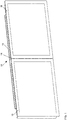
- FIG. 1 schematically shows a front view of a display device 10 according to the invention for a motor vehicle.
- a side view of the display device 10 is shown in FIG Fig. 2 shown.
- the display device 10 is a double display comprising a first Display 11 and a second display 12.
- Each of the displays 11, 12 has a display housing 18 and is overbuilt with a cover glass 19, which is optically bonded to the respective display 11, 12.
- a tolerance compensation between the cover glasses 19 is possible, ie the displays 11, 12 can be aligned relative to each other. By aligning a flush surface transition and a uniform joint 14 between the cover glasses 19 are achieved.
- the compensation elements 15 may be threaded bushes in the display housings 18, for example, which interact with corresponding adjustment screws.
- Fig. 1 and Fig. 2 both displays 11, 12 can be adjusted relative to the holding frame 13. But it is also possible that one of the displays 11, 12 is connected without an adjustment possibility with the holding frame 13. In this case, the holding frame 13 may also be an integral part of the corresponding display housing 18.
- Fig. 3 schematically shows a method for producing a display device with two or more displays for a motor vehicle, wherein the two or more displays have display housing and are optically bonded with a cover glass.
- a first display is attached to a holding frame 20.
- the first display is aligned relative to a second display which is connected to the holding frame, aligned 21.
- the alignment 21 is effected by means of at least one compensation element of the display device.
- To secure the connection over the life of the display device can optionally be done 22 gluing all or some contact surfaces between the display housings and the support frame.
- the second display can be adjustably or unadjustably connected to the support frame. It is also possible that the holding frame is part of the display housing of the second display.
- Fig. 4 schematically illustrates a motor vehicle 30 in which a display device 10 according to the invention is installed.
- the motor vehicle 30 has inter alia a navigation system 31, an infotainment system 32 and a graphics unit 33 for controlling the display device 10.
- a memory 34 may be provided.
- the data provided by the navigation system 31 and the infotainment system 32 are transmitted via a network 35 to the graphics unit 33.
- the graphic displays generated by the graphics unit 33 are output by means of the display device 10.
- the graphics unit 33 is an independent component. She can, however, also in one be integrated with other component, for example, in the infotainment system 32 or the display device 10th
- Fig. 5 shows a front view
- Fig. 6 the associated rear view of a preferred embodiment of the display device 10 of the invention.
- the display device 10 is an assembly consisting of a display control panel as a first display 11, for example, an infotainment display, and a digital instrument cluster as the second display 12.
- the digital instrument cluster For example, it can be a freely programmable instrument cluster.
- the two displays 11, 12 are different in size in the example, but can of course also have the same size.
- Both displays 11, 12 are optically bonded to a respective cover glass 19.
- the display housing 18 of the displays 11, 12 are connected to a holding frame 13 which connects and carries the two displays 11, 12 together.
- the two displays 11, 12 and the holding frame 13 are subject to tolerances in all directions.
- the two displays 11, 12 are adjustably connected to the support frame 13.
- the holding frame has a number of attachment points 16, with the help of the support frame 13 can be connected to an instrument panel.
- mounting pins 17 may be provided to facilitate assembly.
- Fig. 7 shows an exemplary embodiment of a compensating element 15 in detail.
- the cover glass 19 is held by a display support 44, which is connected to the display housing 18.
- an overmolded threaded bushing 40 is inserted, into which an adjustment screw 41 engages.
- a compensating bushing 42 between the adjusting screw 41 and the threaded bushing 40.
- the compensating bushing 42 has a left-handed external thread, which cooperates with a corresponding internal thread of the threaded bushing 40.
- the compensating bush 42 also has a clamping portion 47 which is connected to the adjusting screw 41 by frictional engagement and in overcoming the frictional engagement relative to the adjusting screw 41 is rotatable.
- a clamping portion 47 which is connected to the adjusting screw 41 by frictional engagement and in overcoming the frictional engagement relative to the adjusting screw 41 is rotatable.
- the compensating element 15 can also be formed by threaded rods and locknuts.
- Fig. 8 shows an alternative embodiment of a compensating element 15.
- the cover glass 19 is held by a display support 44 which is connected to the display housing 18.
- an overmolded threaded bushing 40 is inserted, into which an adjustment screw 41 engages.
- the bore 45 is formed largely without play in this embodiment.
- the adjustment screw 41 is fixed by a snap ring 46.
- the display housing 18 is held by the adjusting screw 41 relative to the holding frame 13. Also in this way a tolerance compensation is made possible perpendicular to the display surface. For example, a setting of ⁇ 2mm can be provided.
- Fig. 9 shows a further alternative embodiment of a compensating element 15.
- the cover glass 19 is held by a display support 44 which is connected to the display housing 18.
- the adjustable connection between the display and the holding frame 13 is achieved via a fastening tab 43, which is screwed laterally to the display housing 18 with an adjusting screw 41.
- a threaded bushing or an inserted nut may be provided in the display housing 18 for the adjusting screw 41.
- Fig. 10 shows a detail of another preferred embodiment of the display device according to the invention.
- the holding frame 13 is integrated in the display housing 18 of the first display 11, that is, the first display 11 can not to be adjusted.
- the coverslips 19 are held by associated display carriers 44 which are connected to the display housings 18.
- an overmolded threaded bushing 40 is inserted, in turn, a Justageschraube 41 engages. Between the Justageschraube 41 and the threaded bushing 40 is already out Fig. 7 known balancing socket 42.
- the display housing 18 of the second display 12 is attached to the support frame 13.
- a tolerance compensation of the second display 12 is made possible relative to the first display 11 perpendicular to the display surface.
- a adjustment of ⁇ 2mm can be provided.
- alignment of the second display 12 relative to the first display 11 parallel to the display surface is made possible by a play of the bore 45 for the adjustment screw 41 in the holding frame 13.
Landscapes
- Engineering & Computer Science (AREA)
- Mechanical Engineering (AREA)
- Transportation (AREA)
- Combustion & Propulsion (AREA)
- Chemical & Material Sciences (AREA)
- General Engineering & Computer Science (AREA)
- Theoretical Computer Science (AREA)
- General Physics & Mathematics (AREA)
- Physics & Mathematics (AREA)
- Multimedia (AREA)
- Human Computer Interaction (AREA)
- Microelectronics & Electronic Packaging (AREA)
- Devices For Indicating Variable Information By Combining Individual Elements (AREA)
- Instrument Panels (AREA)
- Fittings On The Vehicle Exterior For Carrying Loads, And Devices For Holding Or Mounting Articles (AREA)
Abstract
Description
- Die vorliegende Erfindung betrifft eine Anzeigevorrichtung für ein Kraftfahrzeug sowie ein Verfahren zur Herstellung einer Anzeigevorrichtung für ein Kraftfahrzeug, insbesondere einer Anzeigevorrichtung mit zwei oder mehr Displays. Die Erfindung betrifft weiterhin ein Kraftfahrzeug, in dem eine erfindungsgemäße Anzeigevorrichtung eingesetzt wird.
- Im Zuge der zunehmenden Nutzung von Displays in Kraftfahrzeugen wird oftmals nicht mehr nur ein einzelnes Display verbaut, beispielsweise als Anzeigevorrichtung für ein Kombiinstrument, sondern eine Gruppe von Displays. So kann z.B. ein Doppeldisplay bestehend aus einem digitalen Kombiinstrument und einem Infotainmentdisplay verbaut sein.
- Bei derartigen Doppeldisplays sollen die einzelnen Displays in der Armaturentafel des Fahrzeugs bündig nebeneinander verbaut sein und wie ein durchgehendes Displayband wirken.
- Eine erste Möglichkeit dies zu erreichen besteht darin, zwei Displays hinter einem gemeinsamen Deckglas anzuordnen. Ohne weitere Maßnahmen treten durch das Deckglas allerdings Reflexionen und Doppelbilder auf, die die Ablesbarkeit der Displays stark verschlechtern. In einem gewissen Umfang kann dies durch die Verwendung eines entspiegelten Deckglases abgemildert werden.
- Bessere Ergebnisse lassen sich erzielen, wenn die zwei Displays mit dem gemeinsamen Deckglas optisch gebondet, d.h. glasklar verklebt werden. Dieser Ansatz erhöht allerdings die Ausschussquote in der Produktion und verhindert eine Mehrlieferantenstrategie für die beiden Displays. Zudem müssen im Reparaturfall bei Defekten beide Displays ausgetauscht werden, was die Reparaturkosten stark erhöht.
- Eine weitere Möglichkeit besteht darin, die einzelnen, jeweils mit einem Deckglas gebondeten Displays in einem gemeinsamen Trägerrahmen zu positionieren, vergleichbar mit einem Bilderrahmen. Ein bündiges Erscheinungsbild der Displays lässt sich damit allerdings nicht erreichen, da immer ein weiteres Bauteil, der Trägerrahmen, zwischen den Displays liegt. Zwar kann der Trägerrahmen farblich angepasst und möglichst flach gestaltet werden, um den Stufensprung von der Displayoberfläche zur Oberfläche des Trägerrahmens gering zu halten, es ergibt sich aber dennoch kein Erscheinungsbild wie bei einem zusammenhängenden Teil.
- Schließlich können die jeweils mit einem Deckglas optisch gebondeten Displays nebeneinander an einem gemeinsamen Halter befestigt werden. Aufgrund der gegebenen Einbaubedingungen und der Toleranzen der Bauteile, insbesondere senkrecht zur Displayoberfläche, ist dies allerdings nicht prozesssicher möglich.
- In Hinblick auf aus einzelnen Displays zusammengesetzte Videowände beschreibt die
EP 3 029 657 A1 ein Display-System. Das Display-System umfasst eine Vielzahl von Anzeigevorrichtungen und ein Gestell, an dem die Anzeigevorrichtungen montiert sind. Das Gestell weist eine Basis auf, mit der das Gestell auf einer horizontalen Fläche aufgestellt werden kann, sowie eine Reihe von Kopplungsrahmen. Die Kopplungsrahmen sind für die Montage jeweils einer Anzeigevorrichtung ausgebildet und derart gestaltet, dass die relative Ausrichtung der Anzeigevorrichtungen eingestellt werden kann. Für die bündige Ausrichtung der Oberflächen der Anzeigevorrichtungen sind dabei drehbare Justagemuttern vorgesehen, die mit entsprechenden festen Justageschrauben zusammenwirken. - Im Hinblick auf elektronische Anzeigetafeln beschreibt die
US 8,844,180 B2 ein elektronisches Schild, das aus einer Vielzahl von Rahmenschränken zusammengesetzt ist. Die Rahmenschränke sind jeweils mit horizontal oder vertikal benachbarten Rahmenschränken verbunden. Die Verbindung erfolgt dabei durch spezielle Verbindungsstücke. In den Rahmenschränken sind LED-Anzeigen montiert. Die Rahmenschränke und die Verbindungsstücke sind derart gestaltet, dass die hergestellten Verbindungen selbstausrichtend sind. - Es ist eine Aufgabe der Erfindung, eine Anzeigevorrichtung für ein Kraftfahrzeug aufzuzeigen, bei der die einzelnen Displays bündig nebeneinander verbaut sind und wie ein durchgehendes Displayband wirken. Es ist eine weitere Aufgabe der Erfindung, ein Verfahren zur Herstellung einer solchen Anzeigevorrichtung aufzuzeigen.
- Diese Aufgaben werden durch eine Anzeigevorrichtung mit den Merkmalen des Anspruchs 1 und durch ein Verfahren mit den Merkmalen des Anspruchs 11 gelöst. Bevorzugte Ausgestaltungen der Erfindung sind Gegenstand der abhängigen Ansprüche.
- Gemäß einem ersten Aspekt der Erfindung umfasst eine Anzeigevorrichtung zwei oder mehr Displays, wobei die zwei oder mehr Displays Displaygehäuse aufweisen und mit je einem Deckglas optisch gebondet sind. Ein Halterahmenverbindet die zwei oder mehr Displays miteinander. Mittels zumindest eines Ausgleichselementes der Anzeigevorrichtung können die zwei oder mehr Displays relativ zueinander ausgerichtet werden.
- Gemäß einem weiteren Aspekt der Erfindung umfasst ein Verfahren zur Herstellung einer Anzeigevorrichtung mit zwei oder mehr Displays für ein Kraftfahrzeug, wobei die zwei oder mehr Displays Displaygehäuse aufweisen und mit je einem Deckglas optisch gebondet sind, die Schritte:
- Befestigen eines ersten Displays an einem Halterahmen; und
- Ausrichten des ersten Displays relativ zu einem zweiten Display, das mit dem Halterahmen verbunden ist, mittels zumindest eines Ausgleichselements der Anzeigevorrichtung.
- Die Verwendung von einem oder mehreren Ausgleichselementen ermöglicht es, Displays mit Deckglas trotz der vorhandenen Toleranzen exakt bündig nebeneinander zu verbauen. Die nahezu toleranzfreie Montage der Displays relativ zueinander bewirkt, dass die Displays wie ein zusammenhängendes Displayband wirken. Während der Montage werden die Displays vorzugsweise mittels einer Montagelehre korrekt ausgerichtet und im Anschluss mit dem Halterahmen verbunden.
- Gemäß einem Aspekt der Erfindung ist jedes der zwei oder mehr Displays relativ zum Halterahmen justierbar. Auf diese Weise können nicht nur Toleranzen der einzelnen Displays relativ zueinander ausgeglichen werden, sondern auch Toleranzen des Halterahmens kompensiert werden.
- Gemäß einem Aspekt der Erfindung ist zumindest eines der zwei oder mehr Displays relativ zum Halterahmen unjustierbar. In diesem Fall ist der Halterahmen entweder Bestandteil des Displaygehäuses eines der zwei oder mehr Displays oder mit dem Displaygehäuse eines der zwei oder mehr Displays unjustierbar verbunden. Das unjustierbare Display fungiert bei hierbei als Referenz für die Justage der weiteren Displays. Zwar lassen sich Toleranzen des Halterahmens bei diesem Ansatz nur noch eingeschränkt ausgleichen, im Gegenzug wird aber durch die Reduzierung der zu justierenden Elemente insgesamt die Justage vereinfacht.
- Gemäß einem Aspekt der Erfindung umfasst das zumindest eine Ausgleichselement eine Gewindebuchse in einem der Displaygehäusen, in die eine Justageschraube eingreift. Vorzugsweise ist zwischen der Gewindebuchse und der Justageschraube eine Ausgleichsbuchse für den Toleranzausgleich angeordnet. Eine derartige Ausgleichsbuchse ist beispielsweise aus der
EP 1 304 489 B1 bekannt. In dieser Ausführung wird eine hohe Klemmkraft und Steifigkeit der Verbindung erreicht, die das Gewicht der Komponenten auch unter dem Einfluss von Vibrationen, Temperaturschwankungen und Alterung sicher tragen kann. Weiterhin ist die Ausrichtung der Bauteile relativ zueinander senkrecht zur Displayoberfläche während des Verschraubens durch Verwendung des Ausgleichselementes automatisch möglich, was den Montageprozess verkürzt. - Gemäß einem Aspekt der Erfindung umfasst das zumindest eine Ausgleichselement eine Gewindestange mit Kontermuttern. Auch mit dieser Ausführung wird eine hohe Klemmkraft und Steifigkeit der Verbindung erreicht. Zudem lässt sich diese Ausführung besonders kostengünstig umsetzen.
- Gemäß einem Aspekt der Erfindung umfasst das zumindest eine Ausgleichselement eine Befestigungslasche des Halterahmens, an der eines der Displaygehäuse seitlich befestigt wird, beispielsweise mit einer Justageschraube. Für die Justageschraube kann eine Gewindebuchse oder eine eingesetzter Mutter im Displaygehäuse vorgesehen sein. Über ein gewisses Spiel der Bohrung für die Justageschraube in der Befestigungslasche ist ein Toleranzausgleich senkrecht zur Displayoberfläche und entlang einer Achse parallel zur Displayoberfläche möglich. Gleichzeitig ist das Ausgleichselement sehr einfach gehalten, so dass es kostengünstig realisiert werden kann.
- Gemäß einem Aspekt der Erfindung weisen Anlageflächen zwischen einem Displaygehäuse und dem Halterahmen eine Verklebung auf. Auf diese Weise ist eine sichere Verbindung der Komponenten über die Lebensdauer der Anzeigevorrichtung auch bei Spannkraftverlust durch Setzvorgänge gewährleistet.
- Gemäß einem Aspekt der Erfindung weist der Halterahmen Befestigungspunkte für eine Armaturentafel auf. Bei dieser Lösung dient der Halterahmen nicht nur zur Verbindung der Displays miteinander, sondern gleichzeitig auch zur Befestigung der gesamten Anzeigevorrichtung in der Armaturentafel. Diese doppelte Verwendung des Halterahmens verringert die Anzahl der zu verbauenden Komponenten.
- Vorzugsweise wird eine erfindungsgemäße Anzeigevorrichtung in einem Fahrzeug, insbesondere einem Kraftfahrzeug, eingesetzt.
- Weitere Merkmale der vorliegenden Erfindung werden aus der nachfolgenden Beschreibung und den angehängten Ansprüchen in Verbindung mit den Figuren ersichtlich.
- Fig. 1
- zeigt schematisch eine Frontansicht einer erfindungsgemäßen Anzeigevorrichtung;
- Fig. 2
- zeigt schematisch eine Seitenansicht der Anzeigevorrichtung aus
Fig. 1 ; - Fig. 3
- zeigt schematisch ein Verfahren zur Herstellung einer erfindungsgemäßen Anzeigevorrichtung;
- Fig. 4
- stellt schematisch ein Kraftfahrzeug dar, in dem eine erfindungsgemäße Anzeigevorrichtung verbaut ist;
- Fig. 5
- zeigt eine Frontansicht einer bevorzugten Ausführungsform der erfindungsgemäßen Anzeigevorrichtung;
- Fig. 6
- zeigt eine Rückansicht der Anzeigevorrichtung aus
Fig. 5 ; - Fig. 7
- zeigt eine Ausgestaltung eines Ausgleichselementes im Detail;
- Fig. 8
- zeigt eine alternative Ausgestaltung eines Ausgleichselementes im Detail;
- Fig. 9
- zeigt eine weitere alternative Ausgestaltung eines Ausgleichselementes im Detail; und
- Fig. 10
- zeigt ein Detail einer weiteren bevorzugten Ausführungsform der erfindungsgemäßen Anzeigevorrichtung.
- Zum besseren Verständnis der Prinzipien der vorliegenden Erfindung werden nachfolgend Ausführungsformen der Erfindung anhand der Figuren detaillierter erläutert. Es versteht sich, dass sich die Erfindung nicht auf diese Ausführungsformen beschränkt und dass die beschriebenen Merkmale auch kombiniert oder modifiziert werden können, ohne den Schutzbereich der Erfindung zu verlassen, wie er in den angehängten Ansprüchen definiert ist.
-
Fig. 1 zeigt schematisch eine Frontansicht einer erfindungsgemäßen Anzeigevorrichtung 10 für ein Kraftfahrzeug. Eine Seitenansicht der Anzeigevorrichtung 10 ist inFig. 2 dargestellt. Bei der Anzeigevorrichtung 10 handelt es sich um ein Doppeldisplay umfassend ein erstes Display 11 und ein zweites Display 12. Jedes der Displays 11, 12 weist ein Displaygehäuse 18 auf und ist mit einem Deckglas 19 überbaut, das mit dem jeweiligen Display 11, 12 optisch gebondet ist. Ein Halterahmen 13, der mit den Displaygehäusen 18 verbunden ist, trägt die beiden Displays 11, 12 und verbindet sie miteinander. Mittels einer oder mehrerer Ausgleichselemente 15 ist ein Toleranzausgleich zwischen den Deckgläsern 19 möglich, d.h. die Displays 11, 12 können relativ zueinander ausgerichtet werden. Durch das Ausrichten werden ein bündiger Flächenübergang und eine gleichmäßige Fuge 14 zwischen den Deckgläsern 19 erzielt. Bei den Ausgleichselementen 15 kann es sich beispielsweise um Gewindebuchsen in den Displaygehäusen 18 handeln, die mit entsprechenden Justageschrauben zusammenwirken. InFig. 1 undFig. 2 können beide Displays 11, 12 relativ zum Halterahmen 13 justiert werden. Es ist aber ebenso möglich, dass eines der Displays 11, 12 ohne eine Justagemöglichkeit mit dem Halterahmen 13 verbunden ist. In diesem Fall kann der Halterahmen 13 auch ein integraler Bestandteil des entsprechenden Displaygehäuses 18 sein. -
Fig. 3 zeigt schematisch ein Verfahren zur Herstellung einer Anzeigevorrichtung mit zwei oder mehr Displays für ein Kraftfahrzeug, wobei die zwei oder mehr Displays Displaygehäuse aufweisen und mit je einem Deckglas optisch gebondet sind. In einem ersten Schritt wird ein erstes Displays an einem Halterahmen befestigt 20. Anschließend wird das erste Display relativ zu einem zweiten Display, das mit dem Halterahmen verbunden ist, ausgerichtet 21. Das Ausrichten 21 erfolgt mittels zumindest eines Ausgleichselementes der Anzeigevorrichtung. Zur Sicherung der Verbindung über die Lebensdauer der Anzeigevorrichtung kann optional ein Verkleben 22 aller oder einiger Anlageflächen zwischen den Displaygehäusen und dem Halterahmen erfolgen. Das zweite Display kann justierbar oder unjustierbar mit dem Halterahmen verbunden sein. Ebenso ist es möglich, dass der Halterahmen Bestandteil des Displaygehäuses des zweiten Displays ist. -
Fig. 4 stellt schematisch ein Kraftfahrzeug 30 dar, in dem eine erfindungsgemäße Anzeigevorrichtung 10 verbaut ist. Das Kraftfahrzeug 30 weist unter anderem ein Navigationssystem 31, ein Infotainmentsystem 32 und eine Grafikeinheit 33 zur Ansteuerung der Anzeigevorrichtung 10 auf. Zudem kann ein Speicher 34 vorgesehen sein. Die vom Navigationssystem 31 und dem Infotainmentsystem 32 bereitgestellten Daten werden über ein Netzwerk 35 an die Grafikeinheit 33 übermittelt. Die von der Grafikeinheit 33 generierten grafischen Anzeigen werden mittels der Anzeigevorrichtung 10 ausgegeben. In der Figur ist die Grafikeinheit 33 eine eigenständige Komponente. Sie kann allerdings auch in eine andere Komponente integriert sein, beispielsweise in das Infotainmentsystem 32 oder die Anzeigevorrichtung 10. - Nachfolgend sollen bevorzugte Ausführungsformen der Erfindung anhand der
Figuren 5 bis 10 erläutert werden. -
Fig. 5 zeigt eine Frontansicht,Fig. 6 die zugehörige Rückansicht einer bevorzugten Ausführungsform der erfindungsgemäßen Anzeigevorrichtung 10. In diesem Beispiel ist die Anzeigevorrichtung 10 eine Baugruppe bestehend aus einem Anzeige-Bedienteil als erstem Display 11, beispielsweise einem Infotainment-Display, und einem digitalem Kombiinstrument als zweitem Display 12. Beim digitalem Kombiinstrument kann es sich beispielsweise um ein frei programmierbares Kombiinstrument handeln. Die beiden Displays 11, 12 sind im Beispiel unterschiedlich groß, können aber selbstverständlich auch die gleiche Größe haben. Beide Displays 11, 12 sind optisch mit einem jeweiligen Deckglas 19 gebondet. Die Displaygehäuse 18 der Displays 11, 12 sind mit einem Halterahmen 13 verbunden, der die beiden Displays 11, 12 miteinander verbindet und trägt. Die beiden Displays 11, 12 und der Halterahmen 13 sind in allen Raumrichtungen toleranzbehaftet. Ein Verbau dieser Elemente mit den üblichen Zentrierungen würde dazu führen, dass die Deckgläser 19 nicht bündig zueinander stehen würden, die Fuge 14 zwischen den Geräten wäre ungleichmäßig. Um einen bündigen Flächenübergang zwischen den Glasoberflächen der Deckgläser 19 und eine gleichmäßige Fuge 14 zwischen den Deckgläsern 19 zu gewährleisten, sind die beiden Displays 11, 12 justierbar mit dem Halterahmen 13 verbunden. Eine Ausrichtung der Displays 11, 12 relativ zueinander erfolgt mittels Ausgleichselementen 15. Für den Einbau im Kraftfahrzeug weist der Halterahmen eine Reihe von Befestigungspunkten 16 auf, mit deren Hilfe der Halterahmen 13 mit einer Instrumententafel verbunden werden kann. Zudem können Montagezapfen 17 zur Erleichterung der Montage vorgesehen sein. -
Fig. 7 zeigt eine beispielhafte Ausgestaltung eines Ausgleichselementes 15 im Detail. Das Deckglas 19 wird von einem Displayträger 44 gehalten, der mit dem Displaygehäuse 18 verbunden ist. In das Displaygehäuse 18 ist eine umspritzte Gewindebuchse 40 eingelassen, in die eine Justageschraube 41 eingreift. Zwischen der Justageschraube 41 und der Gewindebuchse 40 befindet sich eine Ausgleichsbuchse 42. Mittels der Justageschraube 41 und der Ausgleichsbuchse 42 ist das Displaygehäuse 18 am Halterahmen 13 befestigt. Die Ausgleichsbuchse 42 hat ein linksgängiges Außengewinde, das mit einem entsprechenden Innengewinde der Gewindebuchse 40 zusammenwirkt. Die Ausgleichsbuchse 42 hat zudem einen Klemmabschnitt 47, der mit der Justageschraube 41 durch Reibschluss verbunden ist und bei Überwindung des Reibschlusses relativ zur Justageschraube 41 drehbar ist. Beim Einschrauben dreht die Justageschraube 41 somit die Ausgleichsbuchse 42 durch Reibschluss mit, wodurch sich die Ausgleichsbuchse 42 entgegen der Einsteckrichtung aus der Gewindebuchse 40 herausdreht. Sobald sich die Ausgleichsbuchse 42 an den Halterahmen 13 angelegt hat, wird der Reibschluss überwunden und die Justageschraube 41 geht mit einem rechtsgängigen Innengewinde der Gewindebuchse 40 oder der Ausgleichsbuchse 42 eine Schraubverbindung ein. Auf diese Weise wird ein Toleranzausgleich senkrecht zur Displayoberfläche ermöglicht. Beispielsweise kann ein Einstellweg von ±2mm vorgesehen sein. Zudem wird durch ein Spiel der Bohrung 45 für die Justageschraube 41 im Halterahmen 13 eine Ausrichtung des Displays parallel zur Displayoberfläche ermöglicht. Alternativ zur Kombination aus Gewindebuchse 40 und Justageschraube 41 kann das Ausgleichselement 15 auch durch Gewindestangen und Kontermuttern gebildet werden. -
Fig. 8 zeigt eine alternative Ausgestaltung eines Ausgleichselementes 15. Wiederum wird das Deckglas 19 von einem Displayträger 44 gehalten, der mit dem Displaygehäuse 18 verbunden ist. In das Displaygehäuse 18 ist eine umspritzte Gewindebuchse 40 eingelassen, in die eine Justageschraube 41 eingreift. Die Bohrung 45 ist bei dieser Ausgestaltung weitgehend ohne Spiel ausgebildet. Die Justageschraube 41 wird von einem Sprengring 46 fixiert. Das Displaygehäuse 18 wird durch die Justageschraube 41 relativ zum Halterahmen 13 gehalten. Auch auf diese Weise wird ein Toleranzausgleich senkrecht zur Displayoberfläche ermöglicht. Beispielsweise kann ein Einstellweg von ±2mm vorgesehen sein. -
Fig. 9 zeigt eine weitere alternative Ausgestaltung eines Ausgleichselementes 15. Wie zuvor wird das Deckglas 19 von einem Displayträger 44 gehalten, der mit dem Displaygehäuse 18 verbunden ist. In diesem Beispiel wird die einstellbare Verbindung zwischen dem Display und dem Halterahmen 13 über eine Befestigungslasche 43 erreicht, die mit einer Justageschraube 41 seitlich am Displaygehäuse 18 verschraubt wird. Zu diesem Zweck kann für die Justageschraube 41 eine Gewindebuchse oder eine eingesetzter Mutter im Displaygehäuse 18 vorgesehen sein. Über ein gewisses Spiel der Bohrung 45 für die Justageschraube 41 in der Befestigungslasche 43 ist ein Toleranzausgleich senkrecht zur Displayoberfläche und entlang einer Achse parallel zur Displayoberfläche möglich. -
Fig. 10 zeigt ein Detail einer weiteren bevorzugten Ausführungsform der erfindungsgemäßen Anzeigevorrichtung. In dieser Ausführungsform ist der Halterahmen 13 in das Displaygehäuse 18 des ersten Displays 11 integriert, d.h. das erste Display 11 kann nicht justiert werden. Die Deckgläser 19 werden von zugehörigen Displayträgern 44 gehalten, die mit den Displaygehäusen 18 verbunden sind. In das Displaygehäuse 18 des zweiten Displays 12 ist eine umspritzte Gewindebuchse 40 eingelassen, in die wiederum eine Justageschraube 41 eingreift. Zwischen der Justageschraube 41 und der Gewindebuchse 40 befindet sich die bereits ausFig. 7 bekannte Ausgleichsbuchse 42. Mittels der Justageschraube 41 und der Ausgleichsbuchse 42 ist das Displaygehäuse 18 des zweiten Displays 12 am Halterahmen 13 befestigt. Auf diese Weise wird ein Toleranzausgleich des zweiten Displays 12 relativ zum ersten Display 11 senkrecht zur Displayoberfläche ermöglicht. Beispielsweise kann auch hier ein Einstellweg von ±2mm vorgesehen sein. Zudem wird durch ein Spiel der Bohrung 45 für die Justageschraube 41 im Halterahmen 13 eine Ausrichtung des zweiten Displays 12 relativ zum ersten Display 11 parallel zur Displayoberfläche ermöglicht. -
- 10
- Anzeigevorrichtung
- 11
- Erstes Display
- 12
- Zweites Display
- 13
- Halterahmen
- 14
- Fuge
- 15
- Ausgleichselement
- 16
- Befestigungspunkt
- 17
- Montagezapfen
- 18
- Displaygehäuse
- 19
- Deckglas
- 20
- Befestigen des ersten Displays am Halterahmen
- 21
- Ausrichten des ersten Displays
- 22
- Verkleben der Anlageflächen
- 30
- Kraftfahrzeug
- 31
- Navigationssystem
- 32
- Infotainmentsystem
- 33
- Grafikeinheit
- 34
- Speicher
- 35
- Netzwerk
- 40
- Gewindebuchse
- 41
- Justageschraube
- 42
- Ausgleichsbuchse
- 43
- Befestigungslasche
- 44
- Displayträger
- 45
- Bohrung
- 46
- Sprengring
- 47
- Klemmabschnitt
Claims (13)
- Anzeigevorrichtung (10) für ein Kraftfahrzeug (30), mit:- Zwei oder mehr Displays (11, 12), wobei die zwei oder mehr Displays (11, 12) Displaygehäuse (18) aufweisen und mit je einem Deckglas (19) optisch gebondet sind; und- Einem Halterahmen (13), der die zwei oder mehr Displays (11, 12) miteinander verbindet;dadurch gekennzeichnet, dass die Anzeigevorrichtung (10) zumindest ein Ausgleichselement (15) zum Ausrichten der zwei oder mehr Displays (11, 12) relativ zueinander aufweist.
- Anzeigevorrichtung (10) gemäß Anspruch 1, wobei jedes der zwei oder mehr Displays (11, 12) relativ zum Halterahmen (13) justierbar ist.
- Anzeigevorrichtung (10) gemäß Anspruch 1, wobei zumindest eines der zwei oder mehr Displays (11, 12) relativ zum Halterahmen (13) unjustierbar ist.
- Anzeigevorrichtung (10) gemäß Anspruch 3, wobei der Halterahmen (13) Bestandteil des Displaygehäuses (18) eines der zwei oder mehr Displays (11, 12) ist oder mit dem Displaygehäuse (18) eines der zwei oder mehr Displays (11, 12) unjustierbar verbunden ist.
- Anzeigevorrichtung (10) gemäß einem der Ansprüche 1 bis 4, wobei das zumindest eine Ausgleichselement (15) eine Gewindebuchse (40) in einem der Displaygehäusen (18) umfasst, in die eine Justageschraube (41) eingreift.
- Anzeigevorrichtung (10) gemäß Anspruch 5, wobei zwischen der Gewindebuchse (40) und der Justageschraube (41) eine Ausgleichsbuchse (42) angeordnet ist.
- Anzeigevorrichtung (10) gemäß einem der Ansprüche 1 bis 4, wobei das zumindest eine Ausgleichselement (15) eine Gewindestange mit Kontermuttern umfasst.
- Anzeigevorrichtung (10) gemäß einem der Ansprüche 1 bis 4, wobei das zumindest eine Ausgleichselement (15) eine Befestigungslasche (43) des Halterahmens (13) umfasst, an der eines der Displaygehäuse (18) seitlich befestigt wird.
- Anzeigevorrichtung (10) gemäß einem der vorherigen Ansprüche, wobei Anlageflächen zwischen einem Displaygehäuse (18) und dem Halterahmen (13) eine Verklebung aufweisen.
- Anzeigevorrichtung (10) gemäß einem der vorherigen Ansprüche, wobei der Halterahmen (13) Befestigungspunkte (16) für eine Armaturentafel aufweist.
- Verfahren zur Herstellung einer Anzeigevorrichtung (10) mit zwei oder mehr Displays (11, 12) für ein Kraftfahrzeug (30), wobei die zwei oder mehr Displays (11, 12) Displaygehäuse (18) aufweisen und mit je einem Deckglas (19) optisch gebondet sind, mit den Schritten:- Befestigen (20) eines ersten Displays (11) an einem Halterahmen (13); und- Ausrichten (21) des ersten Displays (11) relativ zu einem zweiten Display (12), das mit dem Halterahmen (13) verbunden ist, mittels zumindest eines Ausgleichselementes (15) der Anzeigevorrichtung (10).
- Verfahren gemäß Anspruch 11, wobei Anlageflächen zwischen einem Displaygehäuse (18) und dem Halterahmen (13) verklebt (22) werden.
- Kraftfahrzeug (30), dadurch gekennzeichnet, dass es eine Anzeigevorrichtung (10) gemäß einem der Ansprüche 1 bis 10 aufweist.
Applications Claiming Priority (1)
| Application Number | Priority Date | Filing Date | Title |
|---|---|---|---|
| DE102017210938.6A DE102017210938A1 (de) | 2017-06-28 | 2017-06-28 | Anzeigevorrichtung für ein Kraftfahrzeug, Verfahren zur Herstellung einer Anzeigevorrichtung für ein Kraftfahrzeug |
Publications (2)
| Publication Number | Publication Date |
|---|---|
| EP3421284A1 true EP3421284A1 (de) | 2019-01-02 |
| EP3421284B1 EP3421284B1 (de) | 2020-12-30 |
Family
ID=62386011
Family Applications (1)
| Application Number | Title | Priority Date | Filing Date |
|---|---|---|---|
| EP18173935.0A Active EP3421284B1 (de) | 2017-06-28 | 2018-05-23 | Anzeigevorrichtung für ein kraftfahrzeug, verfahren zur herstellung einer anzeigevorrichtung für ein kraftfahrzeug |
Country Status (5)
| Country | Link |
|---|---|
| US (1) | US10772221B2 (de) |
| EP (1) | EP3421284B1 (de) |
| KR (1) | KR102113675B1 (de) |
| CN (1) | CN109131130B (de) |
| DE (1) | DE102017210938A1 (de) |
Families Citing this family (11)
| Publication number | Priority date | Publication date | Assignee | Title |
|---|---|---|---|---|
| KR102644207B1 (ko) | 2019-10-15 | 2024-03-05 | 현대모비스 주식회사 | 듀얼 디스플레이 플라스틱 렌즈 및 이를 포함하는 디지털 클러스터 |
| TWD205543S (zh) * | 2019-10-31 | 2020-07-01 | 廣達電腦股份有限公司 | 筆記型電腦 |
| TWD204681S (zh) * | 2019-10-31 | 2020-05-11 | 廣達電腦股份有限公司 | 筆記型電腦 |
| CN115135886B (zh) * | 2020-02-07 | 2023-12-22 | 皮尔利斯工业有限公司 | 显示器面板安装系统 |
| DE102020216324A1 (de) * | 2020-12-18 | 2022-06-23 | Witte Automotive Gmbh | Vorrichtung zum Ausgleichen von Toleranzen zwischen einem ersten Bauteil und einem zweiten Bauteil und Anordnung zum Ausgleichen von Toleranzen |
| WO2023032287A1 (ja) * | 2021-09-02 | 2023-03-09 | ソニーグループ株式会社 | 表示装置、表示システム、及び表示方法 |
| JP7792304B2 (ja) * | 2022-06-08 | 2025-12-25 | 株式会社クボタ | 作業車両 |
| DE102022209810B3 (de) * | 2022-09-19 | 2023-12-21 | Continental Automotive Technologies GmbH | Elektronikeinheit für ein Fahrzeug und Herstellungsverfahren |
| DE102023104174A1 (de) | 2023-02-20 | 2024-08-22 | Audi Aktiengesellschaft | Anzeigesystem |
| KR20250014221A (ko) * | 2023-07-19 | 2025-02-03 | 현대모비스 주식회사 | 디스플레이 장치 및 이를 장착한 차량 |
| DE102025110710A1 (de) * | 2025-03-19 | 2026-04-02 | Audi Aktiengesellschaft | Verfahren zum Bereitstellen eines Anzeigesystems |
Citations (7)
| Publication number | Priority date | Publication date | Assignee | Title |
|---|---|---|---|---|
| JPH08268114A (ja) * | 1995-03-30 | 1996-10-15 | Nippon Seiki Co Ltd | 車両用表示装置 |
| EP1304489B1 (de) | 2001-10-18 | 2005-08-10 | Böllhoff GmbH | Toleranzausgleichsanordnung |
| DE102013013356A1 (de) * | 2013-08-09 | 2014-04-03 | Daimler Ag | Baukastensystem für eine Mehrzahl von Bauvarianten einer Instrumententafelanordnung |
| US8777290B1 (en) * | 2013-03-06 | 2014-07-15 | Boese Engineering | Vehicle dashboard instrument assembly |
| US8844180B2 (en) | 2007-04-13 | 2014-09-30 | Daktronics, Inc. | Electronic display mounting system |
| EP3029657A1 (de) | 2014-12-01 | 2016-06-08 | Samsung Electronics Co., Ltd | Mehrsichtanzeigesystem |
| US20160193923A1 (en) * | 2015-01-02 | 2016-07-07 | Hyundai Motor Company | Vehicle including display apparatus |
Family Cites Families (19)
| Publication number | Priority date | Publication date | Assignee | Title |
|---|---|---|---|---|
| US5904328A (en) * | 1997-06-23 | 1999-05-18 | Stb Systems, Inc. | Articulating computer monitor |
| DE19983832T1 (de) * | 1998-12-23 | 2001-11-29 | Jerry Moscovitch | Computer-Anzeigebildschirmsystem und verstellbare Bildschirmhalterung sowie schwenkbare Bildschirme dafür |
| US20030016227A1 (en) * | 2001-07-19 | 2003-01-23 | Matthies Dennis L. | Adaptable large area display |
| WO2003073402A1 (en) * | 2002-02-26 | 2003-09-04 | Norikazu Sato | Multi-display apparatus |
| US7607620B2 (en) * | 2002-09-03 | 2009-10-27 | Bloomberg Finance L.P. | Support for one or more flat panel displays |
| US20050146607A1 (en) * | 2004-01-06 | 2005-07-07 | Romeo Linn | Object Approaching Detection Anti Blind e-Mirrors System |
| JP4413061B2 (ja) * | 2004-04-09 | 2010-02-10 | 株式会社村上開明堂 | ディスプレイ保持装置 |
| US20060082518A1 (en) * | 2004-10-19 | 2006-04-20 | Pranil Ram | Multiple monitor display apparatus |
| US20070000849A1 (en) * | 2005-01-25 | 2007-01-04 | Daktronics, Inc. | Modular display system |
| US7878476B2 (en) * | 2005-03-29 | 2011-02-01 | Xybix Systems, Inc. | Apparatus for mounting a plurality of monitors having adjustable distance to a viewer |
| USD624084S1 (en) * | 2009-06-12 | 2010-09-21 | Steelcase Inc. | Support |
| DE102011076673A1 (de) * | 2011-05-30 | 2012-12-06 | Robert Bosch Gmbh | Vorrichtung zur Anzeige von Informationen |
| DE102011082467B4 (de) | 2011-09-09 | 2022-12-22 | Continental Automotive Technologies GmbH | Anzeige- und Bediensystem für ein Kraftfahrzeug |
| JP2015018936A (ja) * | 2013-07-11 | 2015-01-29 | パナソニックIpマネジメント株式会社 | 電子機器と、それを搭載した自動車 |
| FR3015753B1 (fr) * | 2013-12-20 | 2016-01-29 | Valeo Systemes Thermiques | Dispositif d'affichage destine notamment a un vehicule automobile |
| DE102014220348A1 (de) | 2014-10-08 | 2016-04-14 | Continental Automotive Gmbh | Anzeigeeinrichtung |
| FR3028460B1 (fr) * | 2014-11-19 | 2018-05-11 | Dav | Dispositif d'affichage pour vehicule automobile |
| DE102014019293A1 (de) * | 2014-12-20 | 2016-06-23 | Continental Automotive Gmbh | Elektronikeinheit für ein Kraftfahrzeug und Elektronikeinheit aufweisendes Kraftfahrzeug |
| US20160264065A1 (en) * | 2015-03-12 | 2016-09-15 | Nidec Elesys Corporation | Vehicle-mounted camera, method of manufacturing vehicle-mounted camera, and method of manufacturing vehicle body |
-
2017
- 2017-06-28 DE DE102017210938.6A patent/DE102017210938A1/de not_active Withdrawn
-
2018
- 2018-05-23 EP EP18173935.0A patent/EP3421284B1/de active Active
- 2018-06-25 KR KR1020180072621A patent/KR102113675B1/ko active Active
- 2018-06-28 CN CN201810688064.3A patent/CN109131130B/zh active Active
- 2018-06-28 US US16/021,843 patent/US10772221B2/en active Active
Patent Citations (7)
| Publication number | Priority date | Publication date | Assignee | Title |
|---|---|---|---|---|
| JPH08268114A (ja) * | 1995-03-30 | 1996-10-15 | Nippon Seiki Co Ltd | 車両用表示装置 |
| EP1304489B1 (de) | 2001-10-18 | 2005-08-10 | Böllhoff GmbH | Toleranzausgleichsanordnung |
| US8844180B2 (en) | 2007-04-13 | 2014-09-30 | Daktronics, Inc. | Electronic display mounting system |
| US8777290B1 (en) * | 2013-03-06 | 2014-07-15 | Boese Engineering | Vehicle dashboard instrument assembly |
| DE102013013356A1 (de) * | 2013-08-09 | 2014-04-03 | Daimler Ag | Baukastensystem für eine Mehrzahl von Bauvarianten einer Instrumententafelanordnung |
| EP3029657A1 (de) | 2014-12-01 | 2016-06-08 | Samsung Electronics Co., Ltd | Mehrsichtanzeigesystem |
| US20160193923A1 (en) * | 2015-01-02 | 2016-07-07 | Hyundai Motor Company | Vehicle including display apparatus |
Also Published As
| Publication number | Publication date |
|---|---|
| KR102113675B1 (ko) | 2020-06-17 |
| DE102017210938A1 (de) | 2019-01-03 |
| CN109131130B (zh) | 2022-05-13 |
| CN109131130A (zh) | 2019-01-04 |
| KR20190001928A (ko) | 2019-01-07 |
| EP3421284B1 (de) | 2020-12-30 |
| US20190008056A1 (en) | 2019-01-03 |
| US10772221B2 (en) | 2020-09-08 |
Similar Documents
| Publication | Publication Date | Title |
|---|---|---|
| EP3421284B1 (de) | Anzeigevorrichtung für ein kraftfahrzeug, verfahren zur herstellung einer anzeigevorrichtung für ein kraftfahrzeug | |
| EP3323013B1 (de) | Kopf-oben-anzeigeeinheit mit zumindest einem befestigungselement, anordnung und kraftfahrzeug | |
| DE112011100434T5 (de) | Sicherungseinheit | |
| DE102004022905A1 (de) | Flüssigkristalldisplay und Verfahren zu dessen Herstellung | |
| DE10304259A1 (de) | Befestigung für eine Anzeigeeinheit | |
| DE102017011493B4 (de) | Vorrichtung und Verfahren zur Montage eines Head-Up-Displays | |
| DE19918076C2 (de) | Gehäuse für eine Flüssigkristallanzeige | |
| DE102017006470B3 (de) | Verfahren zur Montage eines Head-up-Displays an einem Modulquerträger eines Fahrzeugs sowie Modulquerträger | |
| WO2021052679A1 (de) | Beleuchtungsvorrichtung für einen kraftfahrzeugscheinwerfer | |
| DE102004057678A1 (de) | Träger für die Fronteinheit eines Kraftfahrzeugs und Montageverfahren | |
| EP0949720B1 (de) | Leiterplatte mit einem Kupplungselement einer Steckvorrichtung | |
| EP2711267B1 (de) | Vorrichtung zum Positionieren und Befestigen eines Lenkgetriebes an einem Kraftfahrzeugaufbau | |
| EP3894742B1 (de) | Beleuchtungsvorrichtung für einen kraftfahrzeugscheinwerfer | |
| EP4048909B1 (de) | Kunststoffgehäusevorrichtung zur indirekten verschraubung für ein kraftfahrzeug | |
| DE102006010064A1 (de) | Aufnahme für Befestigungselement | |
| DE3841661A1 (de) | Optische baugruppe fuer kraftfahrzeuge mit ausfluchtbarer befestigung | |
| DE202014008505U1 (de) | Uhrwerk mit zwei zusammengefügten Modulen | |
| DE60303923T2 (de) | Lagehalter für verbinder | |
| DE102022206039A1 (de) | Hydraulikeinheit | |
| DE102010005310A1 (de) | Montagehilfe | |
| DE102009048527B4 (de) | Anordnung von mehreren Schaltungsträgern und Verfahren zur Herstellung einer derartigen Anordnung | |
| DE102022209810B3 (de) | Elektronikeinheit für ein Fahrzeug und Herstellungsverfahren | |
| DE102007031645B4 (de) | Kombinations-Anzeigeinstrument für ein Kraftfahrzeug | |
| DE202011052516U1 (de) | Befestigungseinrichtung für ein Flächenelement in einem unterhaltungselektronischen Gerät | |
| DE102024208795A1 (de) | Gehäusevorrichtung, Verfahren und Steuervorrichtung zum Herstellen einer Gehäusevorrichtung |
Legal Events
| Date | Code | Title | Description |
|---|---|---|---|
| PUAI | Public reference made under article 153(3) epc to a published international application that has entered the european phase |
Free format text: ORIGINAL CODE: 0009012 |
|
| STAA | Information on the status of an ep patent application or granted ep patent |
Free format text: STATUS: THE APPLICATION HAS BEEN PUBLISHED |
|
| AK | Designated contracting states |
Kind code of ref document: A1 Designated state(s): AL AT BE BG CH CY CZ DE DK EE ES FI FR GB GR HR HU IE IS IT LI LT LU LV MC MK MT NL NO PL PT RO RS SE SI SK SM TR |
|
| AX | Request for extension of the european patent |
Extension state: BA ME |
|
| STAA | Information on the status of an ep patent application or granted ep patent |
Free format text: STATUS: REQUEST FOR EXAMINATION WAS MADE |
|
| 17P | Request for examination filed |
Effective date: 20190702 |
|
| RBV | Designated contracting states (corrected) |
Designated state(s): AL AT BE BG CH CY CZ DE DK EE ES FI FR GB GR HR HU IE IS IT LI LT LU LV MC MK MT NL NO PL PT RO RS SE SI SK SM TR |
|
| STAA | Information on the status of an ep patent application or granted ep patent |
Free format text: STATUS: EXAMINATION IS IN PROGRESS |
|
| 17Q | First examination report despatched |
Effective date: 20191217 |
|
| GRAP | Despatch of communication of intention to grant a patent |
Free format text: ORIGINAL CODE: EPIDOSNIGR1 |
|
| STAA | Information on the status of an ep patent application or granted ep patent |
Free format text: STATUS: GRANT OF PATENT IS INTENDED |
|
| GRAS | Grant fee paid |
Free format text: ORIGINAL CODE: EPIDOSNIGR3 |
|
| INTG | Intention to grant announced |
Effective date: 20201030 |
|
| GRAA | (expected) grant |
Free format text: ORIGINAL CODE: 0009210 |
|
| STAA | Information on the status of an ep patent application or granted ep patent |
Free format text: STATUS: THE PATENT HAS BEEN GRANTED |
|
| AK | Designated contracting states |
Kind code of ref document: B1 Designated state(s): AL AT BE BG CH CY CZ DE DK EE ES FI FR GB GR HR HU IE IS IT LI LT LU LV MC MK MT NL NO PL PT RO RS SE SI SK SM TR |
|
| REG | Reference to a national code |
Ref country code: GB Ref legal event code: FG4D Free format text: NOT ENGLISH |
|
| REG | Reference to a national code |
Ref country code: AT Ref legal event code: REF Ref document number: 1349600 Country of ref document: AT Kind code of ref document: T Effective date: 20210115 |
|
| REG | Reference to a national code |
Ref country code: DE Ref legal event code: R096 Ref document number: 502018003437 Country of ref document: DE |
|
| REG | Reference to a national code |
Ref country code: IE Ref legal event code: FG4D Free format text: LANGUAGE OF EP DOCUMENT: GERMAN |
|
| PG25 | Lapsed in a contracting state [announced via postgrant information from national office to epo] |
Ref country code: RS Free format text: LAPSE BECAUSE OF FAILURE TO SUBMIT A TRANSLATION OF THE DESCRIPTION OR TO PAY THE FEE WITHIN THE PRESCRIBED TIME-LIMIT Effective date: 20201230 Ref country code: FI Free format text: LAPSE BECAUSE OF FAILURE TO SUBMIT A TRANSLATION OF THE DESCRIPTION OR TO PAY THE FEE WITHIN THE PRESCRIBED TIME-LIMIT Effective date: 20201230 Ref country code: NO Free format text: LAPSE BECAUSE OF FAILURE TO SUBMIT A TRANSLATION OF THE DESCRIPTION OR TO PAY THE FEE WITHIN THE PRESCRIBED TIME-LIMIT Effective date: 20210330 Ref country code: GR Free format text: LAPSE BECAUSE OF FAILURE TO SUBMIT A TRANSLATION OF THE DESCRIPTION OR TO PAY THE FEE WITHIN THE PRESCRIBED TIME-LIMIT Effective date: 20210331 |
|
| PG25 | Lapsed in a contracting state [announced via postgrant information from national office to epo] |
Ref country code: BG Free format text: LAPSE BECAUSE OF FAILURE TO SUBMIT A TRANSLATION OF THE DESCRIPTION OR TO PAY THE FEE WITHIN THE PRESCRIBED TIME-LIMIT Effective date: 20210330 Ref country code: LV Free format text: LAPSE BECAUSE OF FAILURE TO SUBMIT A TRANSLATION OF THE DESCRIPTION OR TO PAY THE FEE WITHIN THE PRESCRIBED TIME-LIMIT Effective date: 20201230 Ref country code: SE Free format text: LAPSE BECAUSE OF FAILURE TO SUBMIT A TRANSLATION OF THE DESCRIPTION OR TO PAY THE FEE WITHIN THE PRESCRIBED TIME-LIMIT Effective date: 20201230 |
|
| REG | Reference to a national code |
Ref country code: NL Ref legal event code: MP Effective date: 20201230 |
|
| PG25 | Lapsed in a contracting state [announced via postgrant information from national office to epo] |
Ref country code: HR Free format text: LAPSE BECAUSE OF FAILURE TO SUBMIT A TRANSLATION OF THE DESCRIPTION OR TO PAY THE FEE WITHIN THE PRESCRIBED TIME-LIMIT Effective date: 20201230 |
|
| REG | Reference to a national code |
Ref country code: LT Ref legal event code: MG9D |
|
| PG25 | Lapsed in a contracting state [announced via postgrant information from national office to epo] |
Ref country code: SK Free format text: LAPSE BECAUSE OF FAILURE TO SUBMIT A TRANSLATION OF THE DESCRIPTION OR TO PAY THE FEE WITHIN THE PRESCRIBED TIME-LIMIT Effective date: 20201230 Ref country code: PT Free format text: LAPSE BECAUSE OF FAILURE TO SUBMIT A TRANSLATION OF THE DESCRIPTION OR TO PAY THE FEE WITHIN THE PRESCRIBED TIME-LIMIT Effective date: 20210430 Ref country code: RO Free format text: LAPSE BECAUSE OF FAILURE TO SUBMIT A TRANSLATION OF THE DESCRIPTION OR TO PAY THE FEE WITHIN THE PRESCRIBED TIME-LIMIT Effective date: 20201230 Ref country code: LT Free format text: LAPSE BECAUSE OF FAILURE TO SUBMIT A TRANSLATION OF THE DESCRIPTION OR TO PAY THE FEE WITHIN THE PRESCRIBED TIME-LIMIT Effective date: 20201230 Ref country code: EE Free format text: LAPSE BECAUSE OF FAILURE TO SUBMIT A TRANSLATION OF THE DESCRIPTION OR TO PAY THE FEE WITHIN THE PRESCRIBED TIME-LIMIT Effective date: 20201230 Ref country code: CZ Free format text: LAPSE BECAUSE OF FAILURE TO SUBMIT A TRANSLATION OF THE DESCRIPTION OR TO PAY THE FEE WITHIN THE PRESCRIBED TIME-LIMIT Effective date: 20201230 |
|
| PG25 | Lapsed in a contracting state [announced via postgrant information from national office to epo] |
Ref country code: PL Free format text: LAPSE BECAUSE OF FAILURE TO SUBMIT A TRANSLATION OF THE DESCRIPTION OR TO PAY THE FEE WITHIN THE PRESCRIBED TIME-LIMIT Effective date: 20201230 |
|
| PG25 | Lapsed in a contracting state [announced via postgrant information from national office to epo] |
Ref country code: IS Free format text: LAPSE BECAUSE OF FAILURE TO SUBMIT A TRANSLATION OF THE DESCRIPTION OR TO PAY THE FEE WITHIN THE PRESCRIBED TIME-LIMIT Effective date: 20210430 |
|
| REG | Reference to a national code |
Ref country code: DE Ref legal event code: R097 Ref document number: 502018003437 Country of ref document: DE |
|
| PG25 | Lapsed in a contracting state [announced via postgrant information from national office to epo] |
Ref country code: IT Free format text: LAPSE BECAUSE OF FAILURE TO SUBMIT A TRANSLATION OF THE DESCRIPTION OR TO PAY THE FEE WITHIN THE PRESCRIBED TIME-LIMIT Effective date: 20201230 Ref country code: AL Free format text: LAPSE BECAUSE OF FAILURE TO SUBMIT A TRANSLATION OF THE DESCRIPTION OR TO PAY THE FEE WITHIN THE PRESCRIBED TIME-LIMIT Effective date: 20201230 |
|
| PLBE | No opposition filed within time limit |
Free format text: ORIGINAL CODE: 0009261 |
|
| STAA | Information on the status of an ep patent application or granted ep patent |
Free format text: STATUS: NO OPPOSITION FILED WITHIN TIME LIMIT |
|
| PG25 | Lapsed in a contracting state [announced via postgrant information from national office to epo] |
Ref country code: DK Free format text: LAPSE BECAUSE OF FAILURE TO SUBMIT A TRANSLATION OF THE DESCRIPTION OR TO PAY THE FEE WITHIN THE PRESCRIBED TIME-LIMIT Effective date: 20201230 |
|
| 26N | No opposition filed |
Effective date: 20211001 |
|
| REG | Reference to a national code |
Ref country code: CH Ref legal event code: PL |
|
| PG25 | Lapsed in a contracting state [announced via postgrant information from national office to epo] |
Ref country code: ES Free format text: LAPSE BECAUSE OF FAILURE TO SUBMIT A TRANSLATION OF THE DESCRIPTION OR TO PAY THE FEE WITHIN THE PRESCRIBED TIME-LIMIT Effective date: 20201230 Ref country code: LI Free format text: LAPSE BECAUSE OF NON-PAYMENT OF DUE FEES Effective date: 20210531 Ref country code: LU Free format text: LAPSE BECAUSE OF NON-PAYMENT OF DUE FEES Effective date: 20210523 Ref country code: MC Free format text: LAPSE BECAUSE OF FAILURE TO SUBMIT A TRANSLATION OF THE DESCRIPTION OR TO PAY THE FEE WITHIN THE PRESCRIBED TIME-LIMIT Effective date: 20201230 Ref country code: CH Free format text: LAPSE BECAUSE OF NON-PAYMENT OF DUE FEES Effective date: 20210531 |
|
| REG | Reference to a national code |
Ref country code: BE Ref legal event code: MM Effective date: 20210531 |
|
| PG25 | Lapsed in a contracting state [announced via postgrant information from national office to epo] |
Ref country code: SI Free format text: LAPSE BECAUSE OF FAILURE TO SUBMIT A TRANSLATION OF THE DESCRIPTION OR TO PAY THE FEE WITHIN THE PRESCRIBED TIME-LIMIT Effective date: 20201230 |
|
| PG25 | Lapsed in a contracting state [announced via postgrant information from national office to epo] |
Ref country code: IE Free format text: LAPSE BECAUSE OF NON-PAYMENT OF DUE FEES Effective date: 20210523 |
|
| PG25 | Lapsed in a contracting state [announced via postgrant information from national office to epo] |
Ref country code: IS Free format text: LAPSE BECAUSE OF FAILURE TO SUBMIT A TRANSLATION OF THE DESCRIPTION OR TO PAY THE FEE WITHIN THE PRESCRIBED TIME-LIMIT Effective date: 20210430 |
|
| PG25 | Lapsed in a contracting state [announced via postgrant information from national office to epo] |
Ref country code: BE Free format text: LAPSE BECAUSE OF NON-PAYMENT OF DUE FEES Effective date: 20210531 |
|
| P01 | Opt-out of the competence of the unified patent court (upc) registered |
Effective date: 20230523 |
|
| PG25 | Lapsed in a contracting state [announced via postgrant information from national office to epo] |
Ref country code: NL Free format text: LAPSE BECAUSE OF NON-PAYMENT OF DUE FEES Effective date: 20201230 Ref country code: CY Free format text: LAPSE BECAUSE OF FAILURE TO SUBMIT A TRANSLATION OF THE DESCRIPTION OR TO PAY THE FEE WITHIN THE PRESCRIBED TIME-LIMIT Effective date: 20201230 |
|
| PG25 | Lapsed in a contracting state [announced via postgrant information from national office to epo] |
Ref country code: SM Free format text: LAPSE BECAUSE OF FAILURE TO SUBMIT A TRANSLATION OF THE DESCRIPTION OR TO PAY THE FEE WITHIN THE PRESCRIBED TIME-LIMIT Effective date: 20201230 Ref country code: HU Free format text: LAPSE BECAUSE OF FAILURE TO SUBMIT A TRANSLATION OF THE DESCRIPTION OR TO PAY THE FEE WITHIN THE PRESCRIBED TIME-LIMIT; INVALID AB INITIO Effective date: 20180523 |
|
| PG25 | Lapsed in a contracting state [announced via postgrant information from national office to epo] |
Ref country code: MK Free format text: LAPSE BECAUSE OF FAILURE TO SUBMIT A TRANSLATION OF THE DESCRIPTION OR TO PAY THE FEE WITHIN THE PRESCRIBED TIME-LIMIT Effective date: 20201230 |
|
| PG25 | Lapsed in a contracting state [announced via postgrant information from national office to epo] |
Ref country code: TR Free format text: LAPSE BECAUSE OF FAILURE TO SUBMIT A TRANSLATION OF THE DESCRIPTION OR TO PAY THE FEE WITHIN THE PRESCRIBED TIME-LIMIT Effective date: 20201230 |
|
| REG | Reference to a national code |
Ref country code: AT Ref legal event code: MM01 Ref document number: 1349600 Country of ref document: AT Kind code of ref document: T Effective date: 20230523 |
|
| PG25 | Lapsed in a contracting state [announced via postgrant information from national office to epo] |
Ref country code: AT Free format text: LAPSE BECAUSE OF NON-PAYMENT OF DUE FEES Effective date: 20230523 |
|
| PG25 | Lapsed in a contracting state [announced via postgrant information from national office to epo] |
Ref country code: AT Free format text: LAPSE BECAUSE OF NON-PAYMENT OF DUE FEES Effective date: 20230523 |
|
| PG25 | Lapsed in a contracting state [announced via postgrant information from national office to epo] |
Ref country code: MT Free format text: LAPSE BECAUSE OF FAILURE TO SUBMIT A TRANSLATION OF THE DESCRIPTION OR TO PAY THE FEE WITHIN THE PRESCRIBED TIME-LIMIT Effective date: 20201230 |
|
| PGFP | Annual fee paid to national office [announced via postgrant information from national office to epo] |
Ref country code: DE Payment date: 20250531 Year of fee payment: 8 |
|
| PGFP | Annual fee paid to national office [announced via postgrant information from national office to epo] |
Ref country code: GB Payment date: 20250520 Year of fee payment: 8 |
|
| PGFP | Annual fee paid to national office [announced via postgrant information from national office to epo] |
Ref country code: FR Payment date: 20250526 Year of fee payment: 8 |
|
| PGFP | Annual fee paid to national office [announced via postgrant information from national office to epo] |
Ref country code: AT Payment date: 20260410 Year of fee payment: 5 |