EP3421181A1 - Schraubendreher - Google Patents
Schraubendreher Download PDFInfo
- Publication number
- EP3421181A1 EP3421181A1 EP18180057.4A EP18180057A EP3421181A1 EP 3421181 A1 EP3421181 A1 EP 3421181A1 EP 18180057 A EP18180057 A EP 18180057A EP 3421181 A1 EP3421181 A1 EP 3421181A1
- Authority
- EP
- European Patent Office
- Prior art keywords
- shaft
- screwdriver
- carrier
- handle
- recess
- Prior art date
- Legal status (The legal status is an assumption and is not a legal conclusion. Google has not performed a legal analysis and makes no representation as to the accuracy of the status listed.)
- Granted
Links
Images




Classifications
-
- B—PERFORMING OPERATIONS; TRANSPORTING
- B25—HAND TOOLS; PORTABLE POWER-DRIVEN TOOLS; MANIPULATORS
- B25B—TOOLS OR BENCH DEVICES NOT OTHERWISE PROVIDED FOR, FOR FASTENING, CONNECTING, DISENGAGING, OR HOLDING
- B25B23/00—Details of, or accessories for, spanners, wrenches, screwdrivers
- B25B23/16—Handles
-
- B—PERFORMING OPERATIONS; TRANSPORTING
- B25—HAND TOOLS; PORTABLE POWER-DRIVEN TOOLS; MANIPULATORS
- B25B—TOOLS OR BENCH DEVICES NOT OTHERWISE PROVIDED FOR, FOR FASTENING, CONNECTING, DISENGAGING, OR HOLDING
- B25B15/00—Screwdrivers
- B25B15/02—Screwdrivers operated by rotating the handle
-
- B—PERFORMING OPERATIONS; TRANSPORTING
- B25—HAND TOOLS; PORTABLE POWER-DRIVEN TOOLS; MANIPULATORS
- B25B—TOOLS OR BENCH DEVICES NOT OTHERWISE PROVIDED FOR, FOR FASTENING, CONNECTING, DISENGAGING, OR HOLDING
- B25B23/00—Details of, or accessories for, spanners, wrenches, screwdrivers
- B25B23/0007—Connections or joints between tool parts
- B25B23/0021—Prolongations interposed between handle and tool
-
- B—PERFORMING OPERATIONS; TRANSPORTING
- B25—HAND TOOLS; PORTABLE POWER-DRIVEN TOOLS; MANIPULATORS
- B25B—TOOLS OR BENCH DEVICES NOT OTHERWISE PROVIDED FOR, FOR FASTENING, CONNECTING, DISENGAGING, OR HOLDING
- B25B23/00—Details of, or accessories for, spanners, wrenches, screwdrivers
- B25B23/0007—Connections or joints between tool parts
- B25B23/0035—Connection means between socket or screwdriver bit and tool
-
- B—PERFORMING OPERATIONS; TRANSPORTING
- B25—HAND TOOLS; PORTABLE POWER-DRIVEN TOOLS; MANIPULATORS
- B25G—HANDLES FOR HAND IMPLEMENTS
- B25G1/00—Handle constructions
- B25G1/08—Handle constructions with provision for storing tool elements
- B25G1/085—Handle constructions with provision for storing tool elements for screwdrivers, wrenches or spanners
-
- B—PERFORMING OPERATIONS; TRANSPORTING
- B25—HAND TOOLS; PORTABLE POWER-DRIVEN TOOLS; MANIPULATORS
- B25G—HANDLES FOR HAND IMPLEMENTS
- B25G1/00—Handle constructions
- B25G1/10—Handle constructions characterised by material or shape
- B25G1/105—Handle constructions characterised by material or shape for screwdrivers, wrenches or spanners
Definitions
- the invention relates to a screwdriver with a handle and a first shaft.
- the screwdriver according to the invention has a handle and a first shaft, wherein the handle has a first handle rotatably connected to the first handle portion and a releasably connected to the first handle second handle portion, wherein the second handle member rotatably connected to a second shaft and the second Shank is arranged at least partially releasably in the first handle part, when the two handle parts are connected together.
- the screwdriver according to the invention thus combines two screwdrivers in one tool, namely, on the one hand, a conventional screwdriver with a first shaft and a handle, which consists of the interconnected grip parts, and a second screwdriver, which consists only of the second grip part and the second shaft.
- a conventional screwdriver with a first shaft and a handle, which consists of the interconnected grip parts
- a second screwdriver which consists only of the second grip part and the second shaft.
- two tools in a tool can save resources in the production.
- the screwdriver according to the invention saves space and weight.
- the second shaft is inserted, for example, in the first handle part, so that it is not readily apparent that two screwdrivers are combined.
- first and the second grip part and / or the first and the second shaft have matching coupling means for non-rotatably coupling the first and the second grip part or the first and the second shaft in the connected state.
- the screwdriver can in the connected state characterized as an ordinary one-piece Screwdrivers are used.
- a rotationally fixed coupling can be done for suitable embodiments of the two shafts and / or on the two handle parts.
- Coupling means may also be provided on the handle parts, for example, a hexagonal projection which engages in a matching hexagonal recess on the other handle part.
- the second shaft is shorter than the first shaft.
- the second shaft is formed together with the second handle part as a so-called tots or stubby.
- These are screwdrivers that have a very short handle and a very short shaft and are designed for work in confined spaces.
- the second shaft being shorter than the first shaft, the portion of the second shaft which protrudes beyond the second grip part can be easily accommodated within the first grip part. This makes it possible that only the first shaft and the two handle parts are visible from the outside in the connected state of the two handle parts. At first glance, it does not even show that a screwdriver with a short, second shaft is integrated in the screwdriver.
- the screwdriver can be used in the connected state of the first handle part and the second handle part like an ordinary screwdriver, so without having to be taken into account when operating on the second, short shaft.
- first shaft and the second shaft are aligned with each other in the connected state of the first grip part and the second grip part.
- handle parts which may be formed, for example, rotationally symmetrical. Both when using the screwdriver in the connected state of the first handle part and the second handle part and also when using only the screwdriver with the second handle part and the second shaft haptically results in no significant difference. The operator always attacks the second handle part and possibly also the first handle part.
- the first shaft has a front, provided with a blade or a receiving device for a screwdriver bit and a rear end
- the second shaft has a front, provided with a blade or a receiving device for a screwdriver bit front end and a rear End on, and in the connected state of the first handle portion and the second handle portion, the front end of the second shaft is rotatably connected to the rear end of the first shaft.
- connection of the two handle parts can be formed in a very simple and cost-effective manner as a latching connection, magnetic connection or as a simple plug connection.
- the front end of the second shaft is provided with a recess for receiving a screwdriver bit and the rear end of the first shaft is formed according to a drive training of a screwdriver bit.
- the coupling means for a rotationally fixed coupling of the second shaft to the first shaft can be formed in a very simple manner and in exactly the same manner in which a screwdriver bit is coupled to the recess in the front end of the second shaft.
- first and the second grip part and / or the first and the second shaft have matching holding means for holding the first grip part on the second grip part and / or the first shaft on the second shaft.
- These holding means may be formed, for example, as magnets and / or magnetizable components.
- the holding means In the connected state, the first grip part and the second grip part are held together by the holding means, so that the first grip part and the second grip part do not accidentally come loose during use of the screwdriver.
- the holding means can also hold the first and second shafts in the axial direction against each other, in addition to the rotationally fixed connection by means of the coupling means.
- the holding means are designed as latching means.
- the holding means are used for axial securing.
- tool-free releasable locking means are advantageous.
- the holding means comprise at least one magnet.
- the two handle parts and the two shafts can be quickly, easily and again releasably coupled, the magnets preferably cause a backup against axially acting forces.
- the holding means have at least one spring washer.
- a spring ring can be arranged in a groove on the second shaft and engage in the connected state in a matching groove on the first shaft.
- a coupling of the two handle parts by means of a spring ring would be possible.
- the holding means have at least one rubber ring.
- a rubber ring is also a fast, easy to implement and also again detachable coupling possible.
- at least one rubber ring is used to couple the two handle parts.
- the first grip part has a recess on its rear side, at the outer edge of which the rubber ring is then received in a groove.
- the second handle part has at its front end a matching groove for the rubber ring. If the second grip part is now pressed into the recess on the rear side of the first grip part, the rubber ring constitutes a resistance. As soon as this resistance is overcome, the rubber ring slides into the recess at the front end of the second grip part and the first grip part and the second grip part are thereby coupled with each other.
- the front end of the second shaft can be rotatably coupled to the rear end of the first shaft.
- the rubber ring must thereby take over only coupling forces in the axial direction.
- the rubber ring can also be used as a stop of a arranged in the recess of the first handle portion carrier for screwdriver bits.
- the first grip part has at its rear end a recess for receiving a first carrier for screwdriver bits.
- screwdriver bits can be accommodated in the first handle part, which are then arranged to save space in the handle part and can be removed when using the screwdriver. If several screwdriver bits are arranged in the first handle part, the screwdriver can be used for screwing or unscrewing different screws.
- the first carrier is arranged extendable in the recess of the first handle part.
- the first carrier is locked in an extended position, wherein in an extended position, the second shaft and the first carrier are still connected.
- a separation of the second shaft from the first carrier can for example take place only after overcoming a predefined detent force.
- the first carrier has a recess into which the second shaft can be inserted in sections.
- the second shaft can be arranged to save space and despite the presence of the first carrier in the first handle part, when the two handle parts are connected together.
- first carrier and the second shaft are provided with mating locking means.
- the second shaft pulls the first carrier out of the first grip part.
- the second shaft remains connected to the first carrier, as long as a predefined detent force is overcome.
- the screwdriver bits are easily accessible in the first carrier. After removing a screwdriver bit, the two handle parts can easily be pushed together again and it is not necessary to thread the second shaft in the second carrier. In this way, a bit change to the screwdriver according to the invention can be done quickly and easily. Only when the second shaft is to receive a screwdriver bit, the second shaft is pulled out overcoming the locking force from the recess of the first carrier and is then available for placement with a screwdriver bit or direct use.
- the second handle part has at its rear end a recess for receiving a second carrier for screwdriver bits.
- screwdriver bits can also be arranged in the second handle part.
- the second shaft extends into the recess of the second handle part and the second carrier is slidably disposed on the second shaft.
- the second carrier can be secured to the second handle part and in the extended position, however, the screwdriver bits are very easily accessible in the second carrier.
- the second carrier and the second shaft and / or the second grip part are provided with mating locking means.
- the second carrier can be pulled out only after overcoming a predefined detent force from the second handle part. This prevents the second carrier from inadvertently being pulled out of the second handle portion during use of the screwdriver.
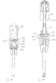
- Fig. 1 shows a screwdriver 10 according to the invention according to the invention obliquely from above.
- the screwdriver has a first shaft 12, a first grip part 14 and a second grip part 16.
- the first shaft 12 is rotatably anchored in the first handle part 14 and has in the illustrated embodiment at its front, in Fig. 1 lower left end 18 a drive training in the form of a recess 20 in the form of a hexagon socket.
- This hexagon socket 20 is provided for receiving a so-called screwdriver bit.
- the screwdriver 10 can be used, for example, to screw in a screw.
- the two handle parts 14, 16 are not integral with each other, but releasably connected to each other and rotatably connected to each other in the connected state.
- Fig. 2 shows the second handle part 16 with the second shaft 22 in a removed from the first handle part 14 state.
- Fig. 3 shows the first grip part 14 with the first shaft 12 without the second grip part 16.
- the second grip part 16 is provided with the second shaft 22.
- the second shaft 22 is significantly shorter than the first shaft 12, but has like the first shaft 12 at its front end 24 has a recess 20 for receiving a screwdriver bit.
- the recesses 20 at the front end of the first shaft 12 and at the front end of the second shaft 22 are formed identical to each other.
- the second handle part 16 forms with the second shaft 22 a full-fledged, short screwdriver, which is also referred to as Knirps or Stubby.
- the second shaft 22 can not be seen because it is inserted in the first grip part 14.
- the two handle parts 14, 16 rotatably coupled together.
- the screwdriver 10 of Fig. 1 Therefore, it can be attacked either on the first grip part 14 or on the second grip part 16 or also on both grip parts 14, 16, with respect to the torque transmission to the first shaft 12, this does not matter.
- the second handle part 16 see Fig. 2 , In its end face, which faces the second shaft 22, provided with two magnets 26.
- the first grip part 14 is likewise provided with magnets and / or a magnetisable component opposite the two magnets 26, so that the two grip parts 14, 16 are also in the connected state by the action of the two magnets 26 Fig. 1 be held together.
- the magnets 26 thus form holding means for securing the two handle parts 14, 16 against each other in the axial direction acting forces.
- the second handle part 16 is provided on its rear side with a cap 28, which can be released from the second handle part 16, which will be explained below.
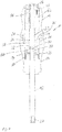
- the presentation of the Fig. 4 shows the screwdriver 10 of Fig. 1 in a sectional view.
- the second handle portion 16 and the rotatably connected to the second handle portion 16 second shaft 22 can be seen.
- the first shaft 12 is injected in a known manner into the first grip part 14, for example, and in the same way the second shaft 22 is secured against rotation on the second grip part 16.
- the front end 24 of the second shaft 22 is connected to a rear end 30 of the first shaft 12 in that the rear end 30 of the first shaft 12 in the recess 20 on front end of the second shaft 22 is inserted.
- the rear end 30 of the first shaft 12 is designed as the drive side of a screwdriver bit, so usually cylindrical with a cross section in the form of a regular hexagon or octagon.
- a magnet 32 is further arranged, which, as in a screwdriver bit, the rear end 30 of the first shaft 12 in the recess 20 holds.
- the magnet 32 thus forms retaining means for axial securing, the recess 20 and the rear end 30 form coupling means for non-rotatable connection.
- a further securing of the rear end 30 of the first shaft 12 is effected by means of a spring ring 34 which is provided on the inner circumference of the recess 20 and engages in the inserted state of the rear end 30 in a matching circumferential groove at the rear end 30.
- the spring ring 34 thus forms a holding means for the axial securing.
- the rear end 30 of the first shaft 12 is configured identically to the rear output end of a screwdriver bit, which is therefore usually plugged into a bit holder.
- the recess 20 in the front end of the second shaft 22 is configured identically as a drive recess for such a screwdriver bit.
- both the first grip part 14 and the second grip part 16 each have two magnets 26.
- the magnets 26 are arranged in the end face of the second gripping part 16, which faces the first gripping part 14, and in the first gripping part 14 the two magnets 26 are arranged in the rear end face, which faces the second gripping part 16.
- a magnet and a magnetizable component may also be located opposite each other.
- the two grip parts 14, 16 are thus coupled with one another via the front end of the second shaft 22 and the rear end of the first shaft 12 as well as via the magnets 26.
- the insertion of the rear end 30 of the first shaft 12 in the recess 20 at the front end of the second shaft 22 provides a rotationally fixed connection of the two handle parts 14, 16.
- the magnets 26 provide an additional, but easily separable securing the two handle parts 14, 16 together. Specifically, the magnets 26 ensure that the mutually facing end faces of the two handle parts 14, 16 remain together and thus in the connected state, the mutually facing end faces of the handle parts 14, 16 do not move relative to each other. This is especially important, therefore, so that when using the screwdriver 12 does not give the impression of a deforming in his hand and thus unsound acting tool.
- the first grip part 16 has a circular cylindrical projection 36, which is arranged concentrically to the second shaft 22 and extends from the front end face of the second grip part 16, see also Fig. 2 ,
- This projection 36 extends into a matching recess at the rear end of the first handle portion 14.
- the two handle portions 14, 16 are secured together so that in the connected state of the optical and haptic impression of a one-piece handle arises.
- the projection 36 and the upper end of the recess 38 may also each have mutually matching hexagonal shapes and then act in the inserted state as a coupling means for rotationally fixed coupling, as they interlock.
- a first carrier 40 is arranged for receiving a plurality of screwdriver bits. This first carrier 40 is arranged extendable in the recess 38, which will be explained below.
- the second grip part 16 is also provided with a recess 42 which extends from the rear end face of the second grip part 16.
- a second carrier 44 is arranged for receiving screwdriver bits.
- the second carrier 44 may be in common with the cap 28, see also Fig. 2 , are pulled out of the rear end of the second handle part 16.
- the screwdriver 10 is thus designed as a so-called magazine screwdriver, since it has two carriers 40, 44 in its grip, which can each be equipped with screwdriver bits 46.
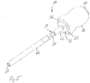
- the presentation of the Fig. 5 shows the screwdriver 10 of Fig. 1 , wherein the first handle part 14 is not shown.
- the first shaft 12 has at its rear end the shape of a cylinder with a cross section in the form of a regular hexagon.
- the rear end 30 of the first shaft 12 has the shape of the output end of a screwdriver bit.
- the rear end 30 of the first shaft 12 is inserted into the depression 20 at the front end of the second shaft 22 and thus the two grip parts 14, 16 or the two shafts 12, 22 are non-rotatable with each other are connected.
- the presentation of the Fig. 6 shows the screwdriver 10 of Fig. 1 , wherein the first handle part 14 has been omitted, but not the first carrier 40, which is guided displaceably in the recess 38 of the first handle part 14, cf. Fig. 4 ,
- the first carrier 40 is guided by means of the ring 50 in the axial direction displaceable in the recess 38 of the first handle part 14.
- the first carrier 40 has a central through hole, in the connected state of the two handle parts 14, 16, see also Fig. 4 , the second shaft 22 is inserted.
- the first carrier 40 is itself slidably disposed in the recess 38, see Fig. 4 , and can, starting from the state of the Fig. 4 to be pulled up.
- the in Fig. 10 is shown, but remains a ring 50 at the front end of the first carrier 40 within the recess 38 and thereby prevents the first carrier 40 is completely pulled out of the first handle portion 14.
- the first carrier 40 has a plurality of brackets 52, in each of which a screwdriver bit can be used. Will the first carrier 40, see Fig. 10 , so far pulled out of the first handle portion 14 that only the ring 50 is disposed within the recess 38 in the first handle portion 14, the screwdriver bits in the brackets 52 are then accessible in a very simple manner.
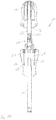
- FIG. 7 shows the screwdriver 10 of Fig. 1 , wherein the two handle parts 14, 16 have been omitted.
- the first shaft 12 the second shaft 22, the first carrier 40 and then also the second carrier 44, which is connected to the cap 28.
- the second carrier 44 is provided with a plurality of holders for insertion of screwdriver bits 46.
- FIG. 8 The presentation of the Fig. 8 shows only the two carriers 40, 44. It is good to see that in the extended state of the carrier 40, the screwdriver bits 46 are easily accessible radially from the outside.
- a central recess 56 can be seen, in which the rear end of the second shaft 22 is inserted.
- the second carrier 44 can thus be moved when pulling out of the second handle part 16 on the rear end of the second shaft 22.
- the first carrier 40 also has a central recess 58 into which, cf. Fig. 4 , the front end of the second shaft 22 is inserted.
- FIG. 9 shows a sectional view of the second handle part 16 with the second shaft 22 in a state in which the second carrier 44 is pulled out of the recess 42 in the second handle part 16.
- the second carrier 44 is pulled out together with the cap 28.
- the rear end of the second shaft 22 slides in the recess 56 in the second carrier 44 until the in Fig. 9 left end of the second carrier 44 abuts a sleeve 60 which has been placed on the rear end of the second shaft 22.
- This cuff 60 forms an end stop and ensures that the second support 44 is captively but slidably secured to the second shaft 22.
- Fig. 9 It can be seen that in the illustrated fully extended state of the second carrier 44, the screwdriver bit 46 is easily accessible.
- the force required for taking off the second carrier 44 from the second handle part 16 and the associated counterforce is denoted by the letter F and an arrow.
- the second carrier 44 For mounting the second handle part 16, the second carrier 44 is first pushed onto the rear end of the second shaft 22 without the cap 28. Subsequently, the sleeve 60 is attached to the rear end of the second shaft 22. The second carrier 44 is now slidably but captively secured on the second shaft 22. Finally, the cap 28 is placed on the in Fig. 9 placed right end of the second carrier 44. The second carrier 44 can now proceed from the in Fig. 9 shown fully extended position are moved to a fully retracted position in which the screwdriver bit 46 is completely hidden and an upper surface of the cap 28 forms a part of the surface of the second handle part 16.
- Fig. 10 shows the screwdriver 10 of Fig. 1 in a state in which the first carrier 40 is completely pulled out of the first grip part 14.
- the ring 50 of the first carrier 40 still remains in the fully extended state within the first grip part 14 and thereby secures the first carrier 40 captive on the first grip part 14.
- the second grip part 16 and the second shaft 22 are in Fig. 10 shown in a detached from the first handle portion 14 state.
- the front end of the second shaft 22 is inserted into the central recess of the first carrier 40 and then in Fig. 10 down, in the direction of the first handle part 14 shifted.
- the front end of the second shaft 22 thereby slides into the first carrier 40 until the in Fig. 10 upper end of the first carrier 40 abuts the outer end face of the projection 36 on the second handle part 16.
- the carrier 40 is pushed into the recess 38 in the first grip part 14.
- the rear end 30 of the first shaft 12 dips into the recess 20 at the front end of the second shaft 22 until the in Fig. 4 and Fig.
- a screwdriver 10 is thereby created, on the one hand in the state of Fig. 1 can be used as a screwdriver of conventional size with a long, first shaft 12. If, on the other hand, the second grip part 16 with the second, short shaft 22 is separated from the first grip part, the second grip part 16 with the short second shaft 22 can likewise be used as a full-fledged screwdriver.
- Such screwdrivers with short handle and short shaft 22 are also referred to as stubby or tots and are intended for work in inaccessible places.
- two carriers 40, 44 are provided for arranging screwdriver bits, so that the screwdriver 10 according to the invention is designed as a so-called magazine screwdriver.
- the two carriers 40, 44 for screwdriver bits are accessible in a simple manner in that the carriers 40, 44 are pulled out of the respective associated grip part 14, 16. Both carriers 40, 44 are captively attached to the respective handle portion 14, 16.
- the screwdriver according to the invention therefore saves resources by the combination of two screwdrivers in a single tool in the production and in the use space and weight is saved.
- Fig. 11 shows in sections cut another screwdriver 100 according to the invention according to the invention.
- the screwdriver differs only in the manner of coupling the first handle portion 114 and the second handle portion 116 and in the arrangement and guidance of the first carrier 140 in the first handle portion 114 of the screwdriver 10 of Fig. 1 to 10 , Below are therefore only the screwdriver 10 of the Fig. 1 to 10 described different parts.
- the first grip part 114 is provided on its rear side facing away from the first shaft 112 with a recess 138 into which the second shaft 122 of the second grip part 116 can be inserted.
- the front end of the second shaft 122 is provided with a recess for receiving a screwdriver bit and the protruding into the recess 138 end of the first shaft 112 is provided at its free end with a drive training of a screwdriver bit.
- a first carrier 140 for screwdriver bits is guided displaceably.
- the carrier 140 is displaceably guided on the inner wall of the recess 138 and by means of a compression spring 170, which has the form of a helical spring in the in Fig. 11 biased shown pushed-out position. In this extended position, the carrier 140 is held by means of a rubber ring 172.
- the carrier 140 is thus captively connected to the first handle portion 114.
- the second handle part 116 is at its front end, the second shaft 122 and in the illustration of Fig. 1 the first handle portion 114, provided with a projection which is provided with a circumferential groove 174.
- the outer diameter of the projection is slightly smaller than the inner diameter of the recess 138 at the rear end of the first handle portion 114.
- the dimensions of the circumferential groove 174 are matched to the rubber ring or O-ring 172 in the recess 138. If now the second handle part 116 is pushed into the recess 138, this movement is first stopped when the projection with the groove 174 impinges on the rubber ring or O-ring 172. By light pressure, the resistance occurring can then be overcome, so that the rubber ring 172 can snap into the groove 174.
- the carrier 140 has, at its section guided on the inner wall of the recess 138, a circumferential shoulder 178 which, in the completely pushed-out state of the Fig. 15 and the Fig. 11 at the over the groove 176 protruding portion of the rubber ring 172 is applied.
- the carrier 140 which may also be referred to as a bit magazine, is thus held captive on the first grip part 114, is automatically removed from the first grip part 114 when the second grip part 116 is removed Fig. 15 shown position and is pushed back into the recess 138 of the first handle portion 114 when connecting the second handle portion 116 with the first handle portion 114.
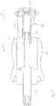
- Fig. 12 shows a sectional view of the second handle portion 116 with the second shaft 122.
- a generally circular cylindrical projection which on the in Fig. 12 shown below surrounds the second shaft 122 and which is provided with the circumferential groove 174.
- the second handle portion 116 has a recess 142 which is substantially the same as in the screwdriver 10 of Fig. 1 to 10 is trained.
- a second carrier 144 is arranged along in the rear part of the second shaft 122, which can also be used as a bit magazine.
- the carrier 144 is connected to a cover 128 which can be pushed onto the back of the second handle portion 116 and the deferred state of Fig. 12 the recess 142 closes.
- a movement of the carrier 144 along the second shaft 122 is stopped by a sleeve-shaped end stop 160, which is placed on the rear end of the second shaft 122. At this annular sleeve strikes the carrier 144 in the fully extended state of Fig. 13 at.
- a circumferential groove 180 for receiving a rubber ring or O-ring 182 provided.
- the O-ring 182 omitted, so that there the circumferential groove 180 in the shaft 122 well can be seen.
- Rubber ring 182 is clamped between the inside of carrier 144 and the bottom of groove 180.
- the carrier 144 in the in Fig. 13 held shown extended position. This is effected by the frictional force between the rubber ring 182 and the inside of the carrier 144. Screwdriver bits can be easily inserted into the carrier 144 or removed therefrom.
- the lid 128 and thus the carrier 144 on the second handle part 116 are held by a suitable fit between the lid 128 and the opening of the recess 142.
- a clamping connection between the in Fig. 12 lower end of the carrier 144 and the matching, the shaft 122 annularly surrounding recess 184 may be provided in the second handle portion 116.
- This in Fig. 12 lower end 186 of the carrier 144 is then latched or clamped in the recess 184, so that the lid 128 securely in the in Fig. 12 shown closed position is held.
- the lid 128 itself is snapped onto the carrier 144.
- suitable locking projections 188 are provided on the cover 128 in the illustrated embodiment, which engage the annular sleeve 160 at the end of the second shaft 122 and there are further locking projections 190 which engage the carrier 144, is provided.
Landscapes
- Engineering & Computer Science (AREA)
- Mechanical Engineering (AREA)
- Details Of Spanners, Wrenches, And Screw Drivers And Accessories (AREA)
Abstract

Description
- Die Erfindung betrifft einen Schraubendreher mit einem Griff und einem ersten Schaft.
- Mit der Erfindung soll ein flexibel einzusetzender und platzsparender Schraubendreher bereitgestellt werden.
- Erfindungsgemäß ist hierzu ein Schraubendreher mit den Merkmalen von Anspruch 1 vorgesehen. Vorteilhafte Weiterbildungen der Erfindung sind in den Unteransprüchen genannt.
- Der erfindungsgemäße Schraubendreher weist einen Griff und einen ersten Schaft auf, wobei der Griff ein mit dem ersten Schaft drehfest verbundenes erstes Griffteil und ein mit dem ersten Griffteil lösbar verbundenes zweites Griffteil aufweist, wobei das zweite Griffteil drehfest mit einem zweiten Schaft verbunden ist und der zweite Schaft mindestens abschnittsweise lösbar im ersten Griffteil angeordnet ist, wenn die beiden Griffteile miteinander verbunden sind.
- Der erfindungsgemäße Schraubendreher kombiniert somit zwei Schraubendreher in einem Werkzeug, nämlich zum einen einen konventionellen Schraubendreher mit einem ersten Schaft und einem Griff, der aus den miteinander verbundenen Griffteilen besteht, und einen zweiten Schraubendreher, der lediglich aus dem zweiten Griffteil und dem zweiten Schaft besteht. In überraschend einfacher Weise lassen sich durch die Erfindung daher zwei Werkzeuge in einem Werkzeug kombinieren. Dadurch können Ressourcen bei der Herstellung eingespart werden. Im Gebrauch spart der erfindungsgemäße Schraubendreher Platz und Gewicht. Im verbundenen Zustand ist der zweite Schaft beispielsweise in das erste Griffteil eingesteckt, so dass nicht ohne weiteres erkennbar ist, dass zwei Schraubendreher kombiniert sind.
- In Weiterbildung der Erfindung weisen das erste und das zweite Griffteil und/oder der erste und der zweite Schaft zueinander passende Koppelmittel auf, um das erste und das zweite Griffteil beziehungsweise den ersten und den zweiten Schaft im verbundenen Zustand drehfest miteinander zu koppeln.
- Durch Vorsehen solcher Koppelmittel ist im verbundenen Zustand des ersten Griffteils und des zweiten Griffteils und/oder im verbundenen Zustand des ersten Schafts und des zweiten Schafts keine Relativdrehung um die Längsachse der beiden Griffteile mehr möglich. Der Schraubendreher kann im verbundenen Zustand dadurch wie ein gewöhnlicher einstückiger Schraubendreher verwendet werden. Eine drehfeste Koppelung kann für geeignete Ausgestaltungen an den beiden Schäften und/oder an den beiden Griffteilen erfolgen. Koppelmittel können auch an den Griffteilen vorgesehen sein, beispielsweise ein sechseckförmiger Vorsprung, der in eine passende sechseckförmige Ausnehmung am anderen Griffteil eingreift.In Weiterbildung der Erfindung ist der zweite Schaft kürzer als der erste Schaft.
- Beispielsweise ist der zweite Schaft zusammen mit dem zweiten Griffteil als sogenannter Knirps oder Stubby ausgebildet. Dies sind Schraubendreher, die einen sehr kurzen Griff und einen sehr kurzen Schaft aufweisen und für Arbeiten in räumlich beengten Umgebungen vorgesehen sind. Indem der zweite Schaft kürzer ist als der erste Schaft, kann der Abschnitt des zweiten Schafts, der über das zweite Griffteil hinausragt, problemlos innerhalb des ersten Griffteils untergebracht werden. Dadurch wird es möglich, dass im verbundenen Zustand der beiden Griffteile lediglich der erste Schaft und die beiden Griffteile von außen sichtbar sind. Auf den ersten Blick ist damit überhaupt nicht zu erkennen, dass auch ein Schraubendreher mit kurzem, zweitem Schaft in dem Schraubendreher integriert ist. Auch kann der Schraubendreher im verbundenen Zustand des ersten Griffteils und des zweiten Griffteils wie ein gewöhnlicher Schraubendreher verwendet werden, also ohne dass bei der Bedienung auf den zweiten, kurzen Schaft Rücksicht genommen werden muss.
- In Weiterbildung der Erfindung fluchten der erste Schaft und der zweite Schaft im verbundenen Zustand des ersten Griffteils und des zweiten Griffteils miteinander.
- Dies erleichtert die Gestaltung der Griffteile, die dadurch beispielsweise rotationssymmetrisch ausgebildet sein können. Sowohl bei der Verwendung des Schraubendrehers im verbundenen Zustand des ersten Griffteils und des zweiten Griffteils und auch bei Verwendung lediglich des Schraubendrehers mit dem zweiten Griffteil und dem zweiten Schaft ergibt sich haptisch kein wesentlicher Unterschied. Der Bediener greift immer am zweiten Griffteil und gegebenenfalls noch am ersten Griffteil an.
- In Weiterbildung der Erfindung weist der erste Schaft ein vorderes, mit einer Klinge oder einer Aufnahmeeinrichtung für ein Schrauberbit versehenes Ende und ein hinteres Ende auf, der zweite Schaft weist ein vorderes, mit einer Klinge oder einer Aufnahmeeinrichtung für ein Schrauberbit versehenes vorderes Ende und ein hinteres Ende auf, und im verbundenen Zustand des ersten Griffteils und des zweiten Griffteils ist das vordere Ende des zweiten Schafts drehfest mit dem hinteren Ende des ersten Schafts verbunden.
- Auf diese Weise kann eine Drehmomentübertragung zwischen dem zweiten Griffteil und dem ersten Griffteil über den zweiten Schaft erfolgen, der drehfest mit dem ersten Schaft über geeignete Koppelmittel gekoppelt ist. Dadurch werden an eine Verbindung der beiden Griffteile nur sehr geringe Anforderungen gestellt, da die Verbindung der beiden Griffteile selbst nicht notwendigerweise ein Drehmoment übertragen muss. Die Verbindung der beiden Griffteile kann dadurch in sehr einfacher und kostengünstiger Weise als Rastverbindung, Magnetverbindung oder auch als einfache Steckverbindung ausgebildet sein.
- In Weiterbildung der Erfindung ist das vordere Ende des zweiten Schafts mit einer Ausnehmung zum Aufnehmen eines Schrauberbits versehen und das hintere Ende des ersten Schafts ist entsprechend einer Antriebsausbildung eines Schrauberbits ausgebildet.
- Auf diese Weise können die Koppelmittel für eine drehfeste Kopplung des zweiten Schafts mit dem ersten Schaft in sehr einfacher Weise und in genau derselben Art und Weise ausgebildet sein, in der ein Schrauberbit mit der Ausnehmung im vorderen Ende des zweiten Schafts gekoppelt wird.
- In Weiterbildung der Erfindung weisen das erste und das zweite Griffteil und/oder der erste und der zweite Schaft zueinander passende Haltemittel auf, um das erste Griffteil am zweiten Griffteil und/oder den ersten Schaft am zweiten Schaft zu halten.
- Diese Haltemittel können beispielsweise als Magnete und/oder magnetisierbare Bauteile ausgebildet sein. Im verbundenen Zustand werden durch die Haltemittel das erste Griffteil und das zweite Griffteil aneinander gehalten, so dass sich das erste Griffteil und das zweite Griffteil nicht versehentlich während der Benutzung des Schraubendrehers voneinander lösen. Die Haltemittel können aber auch den ersten und zweiten Schaft in axialer Richtung aneinander halten, zusätzlich zur drehfesten Verbindung mittels der Koppelmittel.
- In Weiterbildung der Erfindung sind die Haltemittel als Rastmittel ausgebildet.
- Die Haltemittel werden zur axialen Sicherung verwendet. Hierbei sind werkzeuglos lösbare Rastmittel vorteilhaft. In Weiterbildung der Erfindung weisen die Haltemittel wenigstens einen Magneten auf.
- Mittels Magneten lassen sich die beiden Griffteile und auch die beiden Schäfte schnell, einfach und auch wieder voneinander lösbar koppeln, wobei die Magnete vorzugsweise eine Sicherung gegen axial wirkende Kräfte bewirken.
- In Weiterbildung der Erfindung weisen die Haltemittel wenigstens einen Federring auf.
- Beispielsweise kann ein Federring in einer Nut am zweiten Schaft angeordnet sein und im verbundenen Zustand in eine passende Nut am ersten Schaft eingreifen. In ähnlicher Weise wäre auch eine Koppelung der beiden Griffteile mittels eines Federrings möglich.
- In Weiterbildung der Erfindung weisen die Haltemittel wenigstens einen Gummiring auf.
- Mittels eines Gummirings ist ebenfalls eine schnelle, einfach realisierbare und auch wieder voneinander lösbare Koppelung möglich. Vorteilhafterweise wird wenigstens ein Gummiring zur Koppelung der beiden Griffteile eingesetzt. Beispielsweise weist das erste Griffteil an seiner Rückseite eine Ausnehmung auf, an deren äußeren Rand dann der Gummiring in einer Nut aufgenommen ist. Das zweite Griffteil weist an seinem vorderen Ende eine passende Nut für den Gummiring auf. Wird das zweite Griffteil nun in die Ausnehmung an der Rückseite des ersten Griffteils gedrückt, stellt der Gummiring einen Widerstand dar. Sobald dieser Widerstand überwunden ist, rutscht der Gummiring in die Ausnehmung am vorderen Ende des zweiten Griffteils und das erste Griffteil und das zweite Griffteil sind dadurch miteinander gekoppelt. Gleichzeitig kann das vordere Ende des zweiten Schafts mit dem hinteren Ende des ersten Schafts drehfest gekoppelt werden. Der Gummiring muss dadurch lediglich Koppelkräfte in axialer Richtung übernehmen. Zusätzlich kann der Gummiring auch als Anschlag eines in der Ausnehmung des ersten Griffteils angeordneten Trägers für Schrauberbits verwendet werden.
- In Weiterbildung der Erfindung weist das erste Griffteil an seinem hinteren Ende eine Ausnehmung zum Aufnehmen eines ersten Trägers für Schrauberbits auf.
- Auf diese Weise können in dem ersten Griffteil Schrauberbits untergebracht werden, die dann platzsparend im Griffteil angeordnet sind und bei Gebrauch des Schraubendrehers entnommen werden können. Sind mehrere Schrauberbits in dem ersten Griffteil angeordnet, kann der Schraubendreher für das Eindrehen oder Ausdrehen unterschiedlicher Schrauben eingesetzt werden.
- In Weiterbildung der Erfindung ist der erste Träger ausziehbar in der Ausnehmung des ersten Griffteils angeordnet.
- Beispielsweise ist der erste Träger in einer ausgezogenen Stellung arretiert, wobei in einer ausgezogenen Stellung der zweite Schaft und der erste Träger noch verbunden sind. Ein Trennen des zweiten Schafts vom ersten Träger kann beispielsweise erst nach Überwinden einer vordefinierten Rastkraft erfolgen. Indem der erste Träger aus dem ersten Griffteil ausgezogen werden kann, ist es möglich, die Schrauberbits im ausgezogenen Zustand sehr gut zugänglich anzuordnen.
- In Weiterbildung der Erfindung weist der erste Träger eine Ausnehmung auf, in die der zweite Schaft abschnittsweise einschiebbar ist.
- Auf diese Weise kann der zweite Schaft platzsparend und trotz Vorhandensein des ersten Trägers in dem ersten Griffteil angeordnet werden, wenn die beiden Griffteile miteinander verbunden sind.
- In Weiterbildung der Erfindung sind der erste Träger und der zweite Schaft mit zueinander passenden Rastmitteln versehen.
- Werden die beiden Griffteile voneinander weggezogen, zieht dadurch der zweite Schaft den ersten Träger aus dem ersten Griffteil heraus. Der zweite Schaft bleibt aber mit dem ersten Träger verbunden, solange nicht eine vordefinierte Rastkraft überwunden ist. Im ausgezogenen Zustand des ersten Trägers und wenn der zweite Schaft noch mit dem ersten Träger verbunden ist, sind die Schrauberbits im ersten Träger gut zugänglich. Nach Entnehmen eines Schrauberbits können die beiden Griffteile einfach wieder zusammengeschoben werden und es ist nicht erforderlich, den zweiten Schaft in den zweiten Träger einzufädeln. Auf diese Weise kann ein Bitwechsel an dem erfindungsgemäßen Schraubendreher schnell und einfach erfolgen. Erst dann, wenn der zweite Schaft ein Schrauberbit aufnehmen soll, wird der zweite Schaft unter Überwindung der Rastkraft aus der Ausnehmung des ersten Trägers herausgezogen und steht dann für eine Bestückung mit einem Schrauberbit oder eine direkte Verwendung zur Verfügung.
- In Weiterbildung der Erfindung weist das zweite Griffteil an seinem hinteren Ende eine Ausnehmung zum Aufnehmen eines zweiten Trägers für Schrauberbits auf.
- Auf diese Weise können auch in dem zweiten Griffteil Schrauberbits angeordnet werden.
- In Weiterbildung der Erfindung erstreckt sich der zweite Schaft in die Ausnehmung des zweiten Griffteils hinein und der zweite Träger ist verschiebbar auf dem zweiten Schaft angeordnet.
- Auf diese Weise kann der zweite Träger am zweiten Griffteil gesichert sein und in der ausgezogenen Stellung sind dennoch die Schrauberbits in dem zweiten Träger sehr gut zugänglich.
- In Weiterbildung der Erfindung sind der zweite Träger und der zweite Schaft und/oder das zweite Griffteil mit zueinander passenden Rastmitteln versehen.
- Der zweite Träger kann dadurch erst nach Überwinden einer vordefinierten Rastkraft aus dem zweiten Griffteil ausgezogen werden. Dies verhindert, dass der zweite Träger unbeabsichtigt aus dem zweiten Griffteil während der Verwendung des Schraubendrehers ausgezogen wird.
- Weitere Merkmale und Vorteile der Erfindung ergeben sich aus den Ansprüchen und der folgenden Beschreibung bevorzugter Ausführungsformen der Erfindung im Zusammenhang mit den Zeichnungen. Einzelmerkmale der unterschiedlichen Ausführungsformen lassen sich dabei in beliebiger Weise miteinander kombinieren, ohne den Rahmen der Erfindung zu überschreiten. Dies gilt auch für die Kombination von Einzelmerkmalen untereinander ohne die weiteren Merkmale, mit denen die jeweiligen Einzelmerkmale im Zusammenhang beschrieben oder gezeigt sind. In den Zeichnungen zeigen:
- Fig. 1
- eine Ansicht eines erfindungsgemäßen Schraubendrehers von schräg oben,
- Fig. 2
- ein zweites Griffteil mit einem zweiten Schaft, das Bestandteil des Schraubendrehers der
Fig. 1 bildet, - Fig. 3
- ein erstes Griffteil mit einem ersten Schaft, das Bestandteil des Schraubendrehers der
Fig. 1 bildet, - Fig. 4
- eine Schnittansicht des Schraubendrehers der
Fig. 1 , - Fig. 5
- eine Ansicht des Schraubendrehers der
Fig. 1 von schräg oben, wobei das zweite Griffteil nicht dargestellt ist, - Fig. 6
- eine Ansicht des Schraubendrehers der
Fig. 1 von schräg oben, wobei das zweite Griffteil lediglich teilweise weggelassen wurde, so dass ein Träger für Schrauberbits innerhalb des zweiten Griffteils erkennbar ist, - Fig. 7
- eine Ansicht des Schraubendrehers der
Fig. 1 von schräg oben, wobei das erste Griffteil und das zweite Griffteil teilweise weggelassen wurden, so dass ein erster Träger und ein zweiter Träger für Schrauberbits erkennbar sind, - Fig. 8
- eine Darstellung lediglich der beiden Träger für Schrauberbits aus
Fig. 7 , - Fig. 9
- eine schematische Schnittansicht des zweiten Griffteils mit dem zweiten Schaft in einem ausgezogenen Zustand des zweiten Trägers für Schrauberbits,
- Fig. 10
- eine Schnittansicht des Schraubendrehers der
Fig. 4 in einem Zustand, in dem das zweite Griffteil mit dem zweiten Schaft von dem ersten Griffteil getrennt ist, - Fig. 11
- eine abschnittsweise geschnittene Darstellung eines erfindungsgemäßen Schraubendrehers von der Seite im auseinandergezogenen Zustand,
- Fig. 12
- eine Schnittansicht des zweiten Griffteils des Schraubendrehers der
Fig. 12 , - Fig. 13
- eine Schnittansicht des zweiten Griffteils der
Fig. 12 bei ausgezogenem Träger, - Fig. 14
- eine teilweise geschnittene Seitenansicht des Schraubendrehers der
Fig. 11 im zusammengeschobenen Zustand und - Fig. 15
- eine Schnittansicht des Schraubendrehers der
Fig. 11 im auseinandergezogenen Zustand. -
Fig. 1 zeigt einen erfindungsgemäßen Schraubendreher 10 gemäß der Erfindung von schräg oben. Der Schraubendreher weist einen ersten Schaft 12, ein erstes Griffteil 14 und ein zweites Griffteil 16 auf. Der erste Schaft 12 ist drehfest im ersten Griffteil 14 verankert und hat bei der dargestellten Ausführungsform an seinem vorderen, inFig. 1 links unten liegenden Ende 18 eine Antriebsausbildung in Form einer Vertiefung 20 in Form eines Innensechskants. Dieser Innensechskant 20 ist für die Aufnahme eines sogenannten Schrauberbits vorgesehen. Nach dem Einstecken eines Schrauberbits in die Vertiefung 20 kann der Schraubendreher 10 verwendet werden, beispielsweise um eine Schraube einzudrehen. - Die beiden Griffteile 14, 16 sind nicht einstückig miteinander ausgeführt, sondern lösbar miteinander verbunden und im verbundenen Zustand drehfest zueinander.
-
Fig. 2 zeigt das zweite Griffteil 16 mit dem zweiten Schaft 22 in einem vom ersten Griffteil 14 abgenommenen Zustand. -
Fig. 3 zeigt das erste Griffteil 14 mit dem ersten Schaft 12 ohne das zweite Griffteil 16. - In
Fig. 2 ist zu erkennen, dass das zweite Griffteil 16 mit dem zweiten Schaft 22 versehen ist. Der zweite Schaft 22 ist deutlich kürzer als der erste Schaft 12, weist aber wie der erste Schaft 12 an seinem vorderen Ende 24 eine Vertiefung 20 zum Aufnehmen eines Schrauberbits auf. Die Vertiefungen 20 am vorderen Ende des ersten Schafts 12 bzw. am vorderen Ende des zweiten Schafts 22 sind identisch zueinander ausgebildet. Das zweite Griffteil 16 bildet mit dem zweiten Schaft 22 einen vollwertigen, kurzen Schraubendreher, der auch als Knirps oder Stubby bezeichnet wird. - Im verbundenen Zustand des ersten Griffteils 14 und des zweiten Griffteils 16 ist der zweite Schaft 22 nicht zu erkennen, da er in dem ersten Griffteil 14 steckt. Im verbundenen Zustand des ersten Griffteils 14 und des zweiten Griffteils 16 sind die beiden Griffteile 14, 16 drehfest miteinander gekoppelt. Zur Verwendung des Schraubendrehers 10 der
Fig. 1 kann daher entweder am ersten Griffteil 14 oder am zweiten Griffteil 16 oder auch an beiden Griffteilen 14, 16 angegriffen werden, bezüglich der Drehmomentübertragung auf den ersten Schaft 12 spielt dies keine Rolle. - Das zweite Griffteil 16, siehe
Fig. 2 , ist in seiner Stirnfläche, die dem zweiten Schaft 22 zugewandt ist, mit zwei Magneten 26 versehen. Das erste Griffteil 14 ist gegenüberliegend den beiden Magneten 26 ebenfalls mit Magneten und/oder einem magnetisierbaren Bauteil versehen, so dass die beiden Griffteile 14, 16 auch durch die Wirkung der beiden Magneten 26 in dem verbundenen Zustand derFig. 1 aneinander gehalten werden. Die Magnete 26 bilden somit Haltemittel zur Sicherung der beiden Griffteile 14, 16 aneinander gegen in axialer Richtung wirkende Kräfte. - Das zweite Griffteil 16 ist an seiner Rückseite mit einer Kappe 28 versehen, die vom zweiten Griffteil 16 gelöst werden kann, was nachfolgend noch erläutert wird.
- Die Darstellung der
Fig. 4 zeigt den Schraubendreher 10 derFig. 1 in einer Schnittansicht. Zu erkennen sind das erste Griffteil 14 und der drehfest mit dem ersten Griffteil 14 verbundene erste Schaft 12. Darüber hinaus sind das zweite Griffteil 16 und der drehfest mit dem zweiten Griffteil 16 verbundene zweite Schaft 22 zu erkennen. Der erste Schaft 12 ist in bekannter Art und Weise in das erste Griffteil 14 beispielsweise eingespritzt und in gleicher Weise ist der zweite Schaft 22 an dem zweiten Griffteil 16 drehfest gesichert. - In der Schnittansicht der
Fig. 4 ist weiter zu erkennen, dass im verbundenen Zustand der beiden Griffteile 14, 16 das vordere Ende 24 des zweiten Schafts 22 mit einem hinteren Ende 30 des ersten Schafts 12 dadurch verbunden ist, dass das hintere Ende 30 des ersten Schafts 12 in die Vertiefung 20 am vorderen Ende des zweiten Schafts 22 eingeschoben ist. Hierzu ist das hintere Ende 30 des ersten Schafts 12 wie die Antriebsseite eines Schrauberbits gestaltet, also üblicherweise zylindrisch mit einem Querschnitt in Form eines regelmäßigen Sechsecks oder Achtecks. Am Grund der Vertiefung 20 im zweiten Schaft 22 ist darüber hinaus ein Magnet 32 angeordnet, der, wie bei einem Schrauberbit, das hintere Ende 30 des ersten Schafts 12 in der Vertiefung 20 hält. Der Magnet 32 bildet somit Haltemittel zur axialen Sicherung, die Vertiefung 20 und das hintere Ende 30 bilden Koppelmittel zur drehfesten Verbindung. Eine weitere Sicherung des hinteren Endes 30 des ersten Schafts 12 wird mittels eines Federrings 34 bewirkt, der am Innenumfang der Vertiefung 20 vorgesehen ist und der im eingeschobenen Zustand des hinteren Endes 30 in eine passende umlaufende Nut am hinteren Ende 30 eingreift. Auch der Federring 34 bildet somit ein Haltemittel für die axiale Sicherung. - Mit anderen Worten ist das hintere Ende 30 des ersten Schafts 12 identisch ausgestaltet zum hinteren Abtriebsende eines Schrauberbits, das also üblicherweise in einen Bithalter eingesteckt wird. Die Vertiefung 20 im vorderen Ende des zweiten Schafts 22 ist identisch ausgestaltet wie eine Antriebsvertiefung für ein solches Schrauberbit.
- Wie bereits erläutert wurde, weist sowohl das erste Griffteil 14 als auch das zweite Griffteil 16 jeweils zwei Magnete 26 auf. Beim zweiten Griffteil 16 sind die Magnete 26 in der Stirnfläche des zweiten Griffteils 16 angeordnet, die dem ersten Griffteil 14 zugewandt ist, und beim ersten Griffteil 14 sind die beiden Magnete 26 in der hinteren Stirnfläche angeordnet, die dem zweiten Griffteil 16 zugewandt ist. Anstelle von vier Magneten 26 können sich selbstverständlich auch jeweils ein Magnet und ein magnetisierbares Bauteil gegenüberliegen.
- Die beiden Griffteile 14, 16 sind somit einerseits über das vordere Ende des zweiten Schafts 22 und das hintere Ende des ersten Schafts 12 als auch über die Magnete 26 miteinander gekoppelt. Das Einstecken des hinteren Endes 30 des ersten Schafts 12 in die Vertiefung 20 am vorderen Ende des zweiten Schafts 22 sorgt für eine drehfeste Verbindung der beiden Griffteile 14, 16. Die Magnete 26 sorgen für eine zusätzliche, aber leicht trennbare Sicherung der beiden Griffteile 14, 16 aneinander. Speziell sorgen die Magnete 26 dafür, dass die einander zugewandten Stirnflächen der beiden Griffteile 14, 16 aneinander liegen bleiben und somit im verbundenen Zustand sich die einander zugewandten Stirnflächen der Griffteile 14, 16 nicht relativ zueinander bewegen. Dies ist vor allem deshalb von Bedeutung, damit bei der Verwendung des Schraubendrehers 12 nicht der Eindruck eines sich in der Hand verformenden und damit unsolide wirkenden Werkzeugs entsteht.
- Zusätzlich weist das erste Griffteil 16 einen kreiszylinderförmigen Vorsprung 36 auf, der konzentrisch zum zweiten Schaft 22 angeordnet ist und von der vorderen Stirnfläche des zweiten Griffteils 16 ausgeht, siehe auch
Fig. 2 . Dieser Vorsprung 36 erstreckt sich in eine passende Ausnehmung am hinteren Ende des ersten Griffteils 14. Auch über diesen Eingriff des Vorsprungs 36 in eine passende Ausnehmung am ersten Griffteil 14 werden die beiden Griffteile 14, 16 so aneinander gesichert, dass im verbundenen Zustand der optische und haptische Eindruck eines einstückigen Griffs entsteht. Der Vorsprung 36 und das obere Ende der Ausnehmung 38 können auch jeweils zueinander passende Sechskantformen haben und dann im eingesteckten Zustand als Koppelmittel zur drehfesten Koppelung wirken, da diese ineinander greifen. - In der Schnittansicht der
Fig. 4 ist weiter zu erkennen, dass in der Ausnehmung 48 im ersten Griffteil 14, die von der hinteren Stirnfläche des ersten Griffteils 14 ausgeht, ein erster Träger 40 zum Aufnehmen mehrerer Schrauberbits angeordnet ist. Dieser erste Träger 40 ist ausziehbar in der Ausnehmung 38 angeordnet, was nachfolgend noch erläutert wird. - Weiter ist zu erkennen, dass auch das zweite Griffteil 16 mit einer Ausnehmung 42 versehen ist, die von der hinteren Stirnfläche des zweiten Griffteils 16 ausgeht. In dieser Ausnehmung 42 ist ein zweiter Träger 44 zum Aufnehmen von Schrauberbits angeordnet. Der zweite Träger 44 kann gemeinsam mit der Kappe 28, siehe auch
Fig. 2 , aus dem hinteren Ende des zweiten Griffteils 16 herausgezogen werden. - In der Schnittansicht der
Fig. 4 ist in dem zweiten Träger 44 ein schematisch dargestelltes Schrauberbit 46 angeordnet. - Der Schraubendreher 10 ist damit als sogenannter Magazinschraubendreher ausgebildet, da er zwei Träger 40, 44 in seinem Griff aufweist, die jeweils mit Schrauberbits 46 bestückt werden können.
- Die Darstellung der
Fig. 5 zeigt den Schraubendreher 10 derFig. 1 , wobei das erste Griffteil 14 nicht dargestellt ist. Es ist zu erkennen, dass der erste Schaft 12 an seinem hinteren Ende die Form eines Zylinders mit einem Querschnitt in Form eines regelmäßigen Sechsecks hat. Mit anderen Worten hat das hintere Ende 30 des ersten Schafts 12 die Form des Abtriebsendes eines Schrauberbits. Gut zu erkennen ist inFig. 5 , dass im verbundenen Zustand der beiden Griffteile 14, 16 das hintere Ende 30 des ersten Schafts 12 in die Vertiefung 20 am vorderen Ende des zweiten Schafts 22 eingesteckt ist und somit die beiden Griffteile 14, 16 bzw. die beiden Schäfte 12, 22 drehfest miteinander verbunden sind. Wie bei üblichen Schrauberbits ist die Verbindung der beiden Schäfte 12, 22 zwar drehfest, wackelt aber durchaus, wenn Kräfte senkrecht zur Mittellängsachse aufgebracht werden. Um dennoch ein Wackeln der beiden Griffteile 14, 16 gegeneinander zu verhindern, sind, wie bereits erläutert wurde, der kreiszylinderförmige Vorsprung 36 in der vorderen Stirnfläche des zweiten Griffteils 16 und die passende Ausnehmung 38 im hinteren Ende des ersten Griffteils 14 sowie die Magneten 26 vorgesehen. - Die Darstellung der
Fig. 6 zeigt den Schraubendreher 10 derFig. 1 , wobei das erste Griffteil 14 weggelassen wurde, nicht jedoch der erste Träger 40, der in der Ausnehmung 38 des ersten Griffteils 14 verschiebbar geführt ist, vgl.Fig. 4 . Der erste Träger 40 ist dabei mittels des Rings 50 in axialer Richtung verschiebbar in der Ausnehmung 38 des ersten Griffteils 14 geführt. Der erste Träger 40 weist eine zentrale Durchgangsbohrung auf, in die im verbundenen Zustand der beiden Griffteile 14, 16, siehe auchFig. 4 , der zweite Schaft 22 eingeschoben ist. Der erste Träger 40 ist selbst verschiebbar in der Ausnehmung 38 angeordnet, sieheFig. 4 , und kann, ausgehend vom Zustand derFig. 4 , nach oben ausgezogen werden. Auch im ausgezogenen Zustand des ersten Trägers 40, der inFig. 10 dargestellt ist, verbleibt aber ein Ring 50 am vorderen Ende des ersten Trägers 40 innerhalb der Ausnehmung 38 und verhindert dadurch, dass der erste Träger 40 vollständig aus dem ersten Griffteil 14 herausgezogen wird. Wie inFig. 6 zu erkennen ist, weist der erste Träger 40 mehrere Halterungen 52 auf, in die jeweils ein Schrauberbit eingesetzt werden kann. Wird der erste Träger 40, sieheFig. 10 , so weit aus dem ersten Griffteil 14 herausgezogen, dass nur noch der Ring 50 innerhalb der Ausnehmung 38 im ersten Griffteil 14 angeordnet ist, sind die Schrauberbits in den Halterungen 52 dann in sehr einfacher Weise zugänglich. - Die Darstellung der
Fig. 7 zeigt den Schraubendreher 10 derFig. 1 , wobei die beiden Griffteile 14, 16 weggelassen wurden. Zu erkennen sind der erste Schaft 12, der zweite Schaft 22, der erste Träger 40 sowie dann auch der zweite Träger 44, der mit der Kappe 28 verbunden ist. Auch der zweite Träger 44 ist mit mehreren Halterungen zum Einsetzen von Schrauberbits 46 versehen. Wird die Kappe 28 zusammen mit dem zweiten Träger 44 aus dem hinteren Ende des zweiten Griffteils 16 herausgezogen, sieheFig. 9 , sind die Schrauberbits 46 im zweiten Träger 44 in einfacher Weise zugänglich. - Die Darstellung der
Fig. 8 zeigt lediglich die beiden Träger 40, 44. Es ist gut zu erkennen, dass im ausgezogenen Zustand der Träger 40 die Schrauberbits 46 radial von außen her gut zugänglich sind. - Beim zweiten Träger 44 ist eine zentrale Ausnehmung 56 zu erkennen, in die das hintere Ende des zweiten Schafts 22 eingeschoben wird. Der zweite Träger 44 kann somit beim Ausziehen aus dem zweiten Griffteil 16 auf dem hinteren Ende des zweiten Schafts 22 verschoben werden.
- Der erste Träger 40 weist ebenfalls eine zentrale Ausnehmung 58 auf, in die, vgl.
Fig. 4 , das vordere Ende des zweiten Schafts 22 eingeschoben wird. - Die Darstellung der
Fig. 9 zeigt eine Schnittansicht des zweiten Griffteils 16 mit dem zweiten Schaft 22 in einem Zustand, in dem der zweite Träger 44 aus der Vertiefung 42 im zweiten Griffteil 16 ausgezogen ist. Der zweite Träger 44 wird zusammen mit der Kappe 28 ausgezogen. Dabei gleitet das hintere Ende des zweiten Schafts 22 in der Ausnehmung 56 im zweiten Träger 44, bis das inFig. 9 links liegende Ende des zweiten Trägers 44 an eine Manschette 60 stößt, die auf das hintere Ende des zweiten Schafts 22 aufgesetzt wurde. Diese Manschette 60 bildet einen Endanschlag und sorgt dafür, dass der zweite Träger 44 unverlierbar, aber verschiebbar an dem zweiten Schaft 22 befestigt ist.Fig. 9 ist zu entnehmen, dass im dargestellten vollständigen ausgezogenen Zustand des zweiten Trägers 44 das Schrauberbit 46 gut zugänglich ist. Die zum Ausziehen des zweiten Trägers 44 aus dem zweiten Griffteil 16 erforderliche Kraft und die zugehörige Gegenkraft ist jeweils mit dem Buchstaben F und einem Pfeil bezeichnet. - Zum Montieren des zweiten Griffteils 16 wird zunächst der zweite Träger 44 ohne die Kappe 28 auf das hintere Ende des zweiten Schafts 22 aufgeschoben. Daraufhin wird die Manschette 60 auf das hintere Ende des zweiten Schafts 22 aufgesteckt. Der zweite Träger 44 ist nun verschiebbar, aber unverlierbar auf dem zweiten Schaft 22 gesichert. Abschließend wird die Kappe 28 auf das in
Fig. 9 rechts liegende Ende des zweiten Trägers 44 aufgesetzt. Der zweite Träger 44 kann nun ausgehend von der inFig. 9 dargestellten vollständig ausgezogenen Position in eine vollständig eingeschobene Position bewegt werden, in der das Schrauberbit 46 vollständig verdeckt ist und eine Oberseite der Kappe 28einen Teil der Oberfläche des zweiten Griffteils 16 bildet. -
Fig. 10 zeigt den Schraubendreher 10 derFig. 1 in einem Zustand, in dem der erste Träger 40 vollständig aus dem ersten Griffteil 14 herausgezogen ist. Wie bereits erläutert wurde, verbleibt auch im vollständig ausgezogenen Zustand der Ring 50 des ersten Trägers 40 noch innerhalb des ersten Griffteils 14 und sichert dadurch den ersten Träger 40 unverlierbar am ersten Griffteil 14. - Das zweite Griffteil 16 und der zweite Schaft 22 sind in
Fig. 10 in einem vom ersten Griffteil 14 abgenommenen Zustand dargestellt. - Um die beiden Griffteile 14, 16 wieder zu verbinden, wird das vordere Ende des zweiten Schafts 22 in die zentrale Ausnehmung des ersten Trägers 40 gesteckt und dann in
Fig. 10 nach unten, in Richtung auf das erste Griffteil 14 verschoben. Das vordere Ende des zweiten Schafts 22 gleitet dadurch in den ersten Träger 40 hinein, bis das inFig. 10 obere Ende des ersten Trägers 40 an der außenliegenden Stirnfläche des Vorsprungs 36 am zweiten Griffteil 16 anschlägt. Wird nun das zweite Griffteil 16 weiter in Richtung auf das erste Griffteil 14 gedrückt, wird der Träger 40 in die Ausnehmung 38 im ersten Griffteil 14 hineingeschoben. Im weiteren Verlauf taucht das hintere Ende 30 des ersten Schafts 12 in die Vertiefung 20 am vorderen Ende des zweiten Schafts 22 ein, bis die inFig. 4 undFig. 1 dargestellte vollständig eingeschobene Stellung des ersten Trägers 40 erreicht ist. In dieser vollständig eingeschobenen Stellung, sieheFig. 4 , ist der Ring 50 am ersten Träger 40 in einer ringförmigen Ausnehmung 62 innerhalb des ersten Griffteils angeordnet, die die Ausnehmung 38 in Richtung auf das vordere Ende des ersten Schafts 12 fortsetzt. Alternativ liegt Träger 40 im eingeschobenen Zustand nicht am zweiten Griffteil 16 an, sondern nur am zweiten Schaftteil 22. - Mit der Erfindung wird dadurch ein Schraubendreher 10 geschaffen, der zum einen im Zustand der
Fig. 1 als Schraubendreher üblicher Größe mit einem langen, ersten Schaft 12 eingesetzt werden kann. Wird hingegen das zweite Griffteil 16 mit dem zweiten, kurzen Schaft 22 vom ersten Griffteil getrennt, kann das zweite Griffteil 16 mit dem kurzen zweiten Schaft 22 ebenfalls als vollwertiger Schraubendreher eingesetzt werden. Solche Schraubendreher mit kurzem Griff und kurzem Schaft 22 werden auch als Stubby oder Knirps bezeichnet und sind für Arbeiten an unzugänglichen Stellen vorgesehen. Im Griff des Schraubendrehers 10 sind zwei Träger 40, 44 zum Anordnen von Schrauberbits vorgesehen, so dass der erfindungsgemäße Schraubendreher 10 als sogenannter Magazinschraubendreher ausgebildet ist. Die beiden Träger 40, 44 für Schrauberbits sind in einfacher Weise dadurch zugänglich, dass die Träger 40, 44 aus dem jeweils zugeordneten Griffteil 14, 16 herausgezogen werden. Beide Träger 40, 44 sind unverlierbar am jeweiligen Griffteil 14, 16 befestigt. Der erfindungsgemäße Schraubendreher spart durch die Kombination zweier Schraubendreher in einem einzigen Werkzeug daher Ressourcen bei der Herstellung und in der Verwendung wird Platz und Gewicht eingespart. -
Fig. 11 zeigt abschnittsweise geschnitten einen weiteren erfindungsgemäßen Schraubendreher 100 gemäß der Erfindung. Der Schraubendreher unterscheidet sich lediglich in der Art und Weise der Kopplung des ersten Griffteils 114 und des zweiten Griffteils 116 sowie in der Anordnung und Führung des ersten Trägers 140 im ersten Griffteil 114 von dem Schraubendreher 10 derFig. 1 bis 10 . Im Folgenden werden daher lediglich die zum Schraubendreher 10 derFig. 1 bis 10 unterschiedlichen Teile beschrieben. - Das erste Griffteil 114 ist an seiner, dem ersten Schaft 112 abgewandten Rückseite mit einer Ausnehmung 138 versehen, in die der zweite Schaft 122 des zweiten Griffteils 116 eingeschoben werden kann. Das vordere Ende des zweiten Schafts 122 ist mit einer Ausnehmung zum Aufnehmen eines Schrauberbits versehen und das in die Ausnehmung 138 hineinragende Ende des ersten Schafts 112 ist an seinem freien Ende mit einer Antriebsausbildung eines Schrauberbits versehen. Beim Einstecken des zweiten Griffteils 116 und des zweiten Schafts 122 in die Ausnehmung 138 können dadurch das zweite Griffteil 116 und der zweite Schaft 122 drehfest mit dem ersten Schaft 112 und dem ersten Griffteil 114 gekoppelt werden.
- In der Ausnehmung 138 ist auch ein erster Träger 140 für Schrauberbits verschiebbar geführt. Der Träger 140 ist dabei an der Innenwand der Ausnehmung 138 verschiebbar geführt und wird mittels einer Druckfeder 170, die die Form einer Schraubenfeder hat, in die in
Fig. 11 dargestellte ausgeschobene Stellung vorgespannt. In dieser ausgeschobenen Stellung wird der Träger 140 mittels eines Gummirings 172 gehalten. Der Träger 140 ist somit unverlierbar mit dem ersten Griffteil 114 verbunden. - Das zweite Griffteil 116 ist an seinem vorderen Ende, das dem zweiten Schaft 122 und in der Darstellung der
Fig. 1 dem ersten Griffteil 114 zugewandt ist, mit einem Vorsprung versehen, der mit einer umlaufenden Nut 174 versehen ist. Der Außendurchmesser des Vorsprungs ist geringfügig kleiner als der Innendurchmesser der Ausnehmung 138 am hinteren Ende des ersten Griffteils 114. Die Abmessungen der umlaufenden Nut 174 sind auf den Gummiring oder O-Ring 172 in der Ausnehmung 138 abgestimmt. Wird nun das zweite Griffteil 116 in die Ausnehmung 138 hineingeschoben, so wird diese Bewegung zunächst gestoppt, wenn der Vorsprung mit der Nut 174 auf den Gummiring oder O-Ring 172 auftrifft. Durch leichten Druck kann der auftretende Widerstand dann überwunden werden, so dass der Gummiring 172 in die Nut 174 einschnappen kann. Dadurch ist der vollständig eingeschobene Zustand des zweiten Griffteils 116 in das erste Griffteil 114 erreicht, sieheFig. 14 , und der Gummiring 172 hält das zweite Griffteil 116 in der inFig. 14 dargestellten vollständig eingeschobenen Position am ersten Griffteil 114. Beim Ausziehen des zweiten Griffteils 116 muss dann der Widerstand des Gummirings 172 überwunden werden, um das zweite Griffteil 116 wieder aus der Ausnehmung 138 im ersten Griffteil 114 herausziehen zu können. Bei dieser Ausziehbewegung verbleibt der Gummiring 172 in einer Nut an der Innenwand der Ausnehmung 138. Dies deshalb, da die Nut 176, in der der Gummiring 172 im ersten Griffteil 114 aufgenommen ist, tiefer ausgeführt ist als die Nut 174 am zweiten Griffteil 116. Beim Ausziehen des zweiten Griffteils 116, ausgehend vom Zustand derFig. 14 , rutscht die Nut 174 daher über den Gummiring 172 hinaus, so dass der inFig. 15 dargestellte Zustand erreicht werden kann, indem das zweite Griffteil 116 vom ersten Griffteil 114 getrennt ist. - In
Fig. 14 ist zu erkennen, dass im vollständig eingeschobenen Zustand des zweiten Griffteils 116 in das erste Griffteil 114 der Träger 140 vollständig in der Ausnehmung 138 im ersten Griffteil 114 aufgenommen ist. Ausgehend von der inFig. 11 oderFig. 15 dargestellten Position wird der Träger 140 mit dem zweiten Griffteil 116 in die inFig. 14 dargestellte Position gedrückt. Diese Bewegung erfolgt gegen die Druckkraft der Feder 170, die im Zustand derFig. 14 vollständig zusammengedrückt ist und den Träger 140 in Richtung gegen das zweite Griffteil 116 vorspannt. Beim Ausziehen des zweiten Griffteils wird sich der Träger 140 infolgedessen unter der Wirkung der Feder 170 selbsttätig in die inFig. 15 dargestellte ausgeschobene Position bewegen. Wie ausgeführt wurde, wird der Träger 140 in der inFig. 15 dargestellten vollständig ausgeschobenen Position dabei durch den Gummiring 172 im ersten Griffteil 114 gehalten. Der Träger 140 weist hierzu an seinem an der Innenwand der Ausnehmung 138 geführten Abschnitt eine umlaufende Schulter 178 auf, die im vollständig ausgeschobenen Zustand derFig. 15 und derFig. 11 an dem über die Nut 176 hinausragenden Abschnitt des Gummirings 172 anliegt. - Der Träger 140, der auch als Bitmagazin bezeichnet werden kann, ist also unverlierbar am ersten Griffteil 114 gehalten, wird beim Abziehen des zweiten Griffteils 116 vom ersten Griffteil 114 automatisch in die in
Fig. 15 dargestellte Stellung ausgeschoben und wird beim Verbinden des zweiten Griffteils 116 mit dem ersten Griffteil 114 wieder in die Ausnehmung 138 des ersten Griffteils 114 eingeschoben. -
Fig. 12 zeigt eine Schnittansicht des zweiten Griffteils 116 mit dem zweiten Schaft 122. In dieser Ansicht zu erkennen ist der an der Vorderseite des zweiten Griffteils 116 angeordnete allgemein kreiszylindrische Vorsprung, der an der inFig. 12 unten dargestellten Vorderseite den zweiten Schaft 122 umgibt und der mit der umlaufenden Nut 174 versehen ist. - Im hinteren Teil, in
Fig. 12 oben dargestellt, des zweiten Griffteils 116 ist eine Ausnehmung 142 angeordnet, die im Wesentlichen gleich wie bei dem Schraubendreher 10 derFig. 1 bis 10 ausgebildet ist. In der Ausnehmung 142 ist entlang im hinteren Teil des zweiten Schafts 122 ein zweiter Träger 144 angeordnet, der ebenfalls als Bitmagazin eingesetzt werden kann. Der Träger 144 ist mit einem Deckel 128 verbunden, der auf die Rückseite des zweiten Griffteils 116 aufgeschoben werden kann und der im aufgeschobenen Zustand derFig. 12 die Ausnehmung 142 verschließt. - Wird der Deckel ausgehend von dem Zustand der
Fig. 12 nach oben von dem zweiten Griffteil 116 abgezogen, bleibt der Deckel 128 mit dem Träger 144 verbunden und der Träger 144 kann entlang dem zweiten Schaft 122 in die inFig. 13 dargestellte vollständig ausgezogene Stellung verschoben werden, in denen der Träger 144 größtenteils außerhalb der Ausnehmung 142 im zweiten Griffteil 116 angeordnet ist. In dieser Position können dann Schrauberbits aus dem Träger 144 entnommen oder in diesen eingesetzt werden. - Eine Bewegung des Trägers 144 entlang dem zweiten Schaft 122 wird durch einen hülsenförmigen Endanschlag 160 gestoppt, der auf das hintere Ende des zweiten Schafts 122 aufgesetzt ist. An dieser ringförmigen Hülse schlägt der Träger 144 im vollständig ausgezogenen Zustand der
Fig. 13 an. - Um den Träger 144 in dieser vollständig ausgezogenen Stellung zu halten, ist in Richtung auf das in
Fig. 13 unten dargestellte vordere Ende des zweiten Schafts 122 eine umlaufende Nut 180 zur Aufnahme eines Gummirings oder O-Rings 182 vorgesehen. Zur Verdeutlichung ist inFig. 12 der O-Ring 182 weggelassen, so dass dort die umlaufende Nut 180 im Schaft 122 gut zu erkennen ist. Im vollständig ausgezogenen Zustand des Trägers 144 derFig. 13 wird der Gummiring 182 zwischen der Innenseite des Trägers 144 und dem Grund der Nut 180 eingeklemmt. Dadurch wird der Träger 144 in der inFig. 13 dargestellten ausgezogenen Stellung gehalten. Dies wird durch die Reibungskraft zwischen dem Gummiring 182 und der Innenseite des Trägers 144 bewirkt. Schrauberbits können dadurch problemlos in den Träger 144 eingesetzt oder aus diesem entnommen werden. - Im geschlossenen Zustand der
Fig. 12 wird der Deckel 128 und damit der Träger 144 am zweiten Griffteil 116 beispielsweise durch eine geeignete Passung zwischen dem Deckel 128 und der Öffnung der Ausnehmung 142 gehalten. Beispielsweise kann aber auch eine Klemmverbindung zwischen dem inFig. 12 unteren Ende des Trägers 144 und der passenden, den Schaft 122 ringförmig umgebenden Ausnehmung 184 im zweiten Griffteil 116 vorgesehen sein. Das inFig. 12 untere Ende 186 des Trägers 144 wird dann rastend oder klemmend in der Ausnehmung 184 gehalten, so dass der Deckel 128 sicher in der inFig. 12 dargestellten geschlossenen Stellung gehalten wird. - Der Deckel 128 selbst ist auf dem Träger 144 aufgerastet. Hierzu sind an dem Deckel 128 in der dargestellten Ausführungsform geeignete Rastvorsprünge 188 vorgesehen, die an der ringförmigen Hülse 160 am Ende des zweiten Schafts 122 einrasten und es sind weitere Rastvorsprünge 190, die am Träger 144 einrasten, vorgesehen.
Claims (15)
- Schraubendreher (10) mit einem Griff und einem ersten Schaft (12), dadurch gekennzeichnet, dass der Griff ein mit dem ersten Schaft (12) drehfest verbundenes erstes Griffteil (14) und ein mit dem ersten Griffteil (14) lösbar verbundenes zweites Griffteil (16) aufweist, wobei das zweite Griffteil (16) drehfest mit einem zweiten Schaft (22) verbunden ist und der zweite Schaft (22) im miteinander verbundenen Zustand der Griffteile (14, 16) mindestens abschnittsweise lösbar im ersten Griffteil (14) angeordnet ist..
- Schraubendreher nach Anspruch 1, dadurch gekennzeichnet, dass das erste und das zweite Griffteil (14, 16) und/oder der erste und der zweite Schaft (12, 22) zueinander passende Koppelmittel aufweisen, um diese im verbundenen Zustand drehest miteinander zu koppeln.
- Schraubendreher nach Anspruch 1 oder 2, dadurch gekennzeichnet, dass der zweite Schaft (22) kürzer ist als der erste Schaft (12).
- Schraubendreher nach einer der vorstehenden Ansprüche, dadurch gekennzeichnet, dass der erste Schaft (12) und der zweite Schaft (22) im verbundenen Zustand des ersten Griffteils (14) und des zweiten Griffteils (16) miteinander fluchten.
- Schraubenddreher nach wenigstens einem der vorstehenden Ansprüche, dadurch gekennzeichnet, dass der erste Schaft (12) ein vorderes, mit einer Klinge oder einer Aufnahmeeinrichtung für ein Schrauberbit versehenes Ende (18) und ein hinteres Ende (30) aufweist, dass der zweite Schaft (22) ein vorderes, mit einer Klinge oder einer Aufnahmeeinrichtung für ein Schrauberbit versehenes Ende (24) und ein hinteres Ende aufweist, wobei im verbundenen Zustand des ersten Griffteils (14) und des zweiten Griffteils (16) das vordere Ende (24) des zweiten Schafts (22) drehfest mit dem hinteren Ende (30) des ersten Schafts (12) verbunden ist.
- Schraubendreher nach Anspruch 5, dadurch gekennzeichnet, dass das vordere Ende (24) des zweiten Schafts (22) mit einer Ausnehmung (20) zum Aufnehmen eines Schrauberbits versehen ist und das hintere Ende (30) des ersten Schafts (12) entsprechend einer Antriebsausbildung, insbesondere eines Außensechskants, eines Schrauberbits ausgebildet ist.
- Schraubendreher nach wenigstens einem der vorstehenden Ansprüche, dadurch gekennzeichnet, dass das erste und das zweite Griffteil (14, 16) und/oder der erste und der zweite Schaft (12, 22) zueinander passende Haltemittel aufweisen, um das erste Griffteil (14) am zweiten Griffteil (16) und/oder dem ersten Schaft (12) am zweiten Schaft (22) zu halten.
- Schraubendreher nach Anspruch 7, dadurch gekennzeichnet, dass die Haltemittel als Rastmittel ausgebildet sind, dass die Haltemittel wenigstens einen Magneten (26, 32) aufweisen und/oder dass die Haltemittel wenigstens einen Federring (34) aufweisen, und/oder dass die Haltemittel wenigstens einen Gummiring aufweisen.
- Schraubendreher nach wenigstens einem der vorstehenden Ansprüche, dadurch gekennzeichnet, dass das erste Griffteil (14) an seinem hinteren Ende eine Ausnehmung (38) zum Aufnehmen eines ersten Trägers (40) für Schrauberbits (46) aufweist.
- Schraubendreher nach Anspruch 9, dadurch gekennzeichnet, dass der erste Träger (40) ausziehbar in der Ausnehmung (38) des ersten Griffteils (14) angeordnet ist.
- Schraubendreher nach Anspruch 9 oder 10, dadurch gekennzeichnet, dass der erste Träger (40) eine Ausnehmung aufweist, in die der zweite Schaft (22) mindestens abschnittsweise einschiebbar ist.
- Schraubendreher nach Anspruch 9, 10 oder 11, dadurch gekennzeichnet, dass der erste Träger (40) und der zweite Schaft (22) mit zueinander passenden Rastmitteln versehen sind.
- Schraubendreher nach wenigstens einem der vorstehenden Ansprüche, dadurch gekennzeichnet, dass das zweite Griffteil (16) an seinem hinteren Ende eine Ausnehmung (42) zum Aufnehmen eines zweiten Trägers (44) für Schrauberbits (46) aufweist.
- Schraubendreher nach wenigstens einem der vorstehenden Ansprüche, dadurch gekennzeichnet, dass sich der zweite Schaft (22) in die Ausnehmung (42) des zweiten Griffteils (16) hineinerstreckt und dass der zweite Träger (44) verschiebbar auf dem zweiten Schaft (22) angeordnet ist.
- Schraubendreher nach Anspruch 14, dadurch gekennzeichnet, dass der zweite Träger (44) und der zweite Schaft (22) und/oder das zweite Griffteil (16) mit zueinander passenden Rastmitteln versehen sind.
Priority Applications (2)
| Application Number | Priority Date | Filing Date | Title |
|---|---|---|---|
| PL18180057T PL3421181T3 (pl) | 2017-06-30 | 2018-06-27 | Wkrętak |
| SI201830202T SI3421181T1 (sl) | 2017-06-30 | 2018-06-27 | Izvijač |
Applications Claiming Priority (1)
| Application Number | Priority Date | Filing Date | Title |
|---|---|---|---|
| DE102017211118.6A DE102017211118A1 (de) | 2017-06-30 | 2017-06-30 | Schraubendreher |
Publications (3)
| Publication Number | Publication Date |
|---|---|
| EP3421181A1 true EP3421181A1 (de) | 2019-01-02 |
| EP3421181B1 EP3421181B1 (de) | 2020-11-25 |
| EP3421181B9 EP3421181B9 (de) | 2021-05-19 |
Family
ID=62814829
Family Applications (1)
| Application Number | Title | Priority Date | Filing Date |
|---|---|---|---|
| EP18180057.4A Active EP3421181B9 (de) | 2017-06-30 | 2018-06-27 | Schraubendreher |
Country Status (10)
| Country | Link |
|---|---|
| EP (1) | EP3421181B9 (de) |
| CN (1) | CN109202798B (de) |
| DE (1) | DE102017211118A1 (de) |
| DK (1) | DK3421181T3 (de) |
| ES (1) | ES2850823T3 (de) |
| HU (1) | HUE053512T2 (de) |
| PL (1) | PL3421181T3 (de) |
| PT (1) | PT3421181T (de) |
| SI (1) | SI3421181T1 (de) |
| TW (1) | TWI680841B (de) |
Cited By (1)
| Publication number | Priority date | Publication date | Assignee | Title |
|---|---|---|---|---|
| WO2020254456A1 (de) * | 2019-06-21 | 2020-12-24 | Wera Werkzeuge Gmbh | Schraubwerkzeug mit magazin |
Citations (4)
| Publication number | Priority date | Publication date | Assignee | Title |
|---|---|---|---|---|
| US4300607A (en) * | 1980-03-07 | 1981-11-17 | Mellinger Ralph D | Variable length tool handle |
| US6220129B1 (en) * | 1999-06-11 | 2001-04-24 | Innovak D.I.Y. Products Inc. | Dual multi-bit screwdriver |
| DE20218261U1 (de) * | 2002-10-22 | 2003-01-23 | Kao, Li-Wen, Tainan | Handwerkzeug-Baugruppe |
| US20100108562A1 (en) * | 2008-10-30 | 2010-05-06 | Tsai-Ching Chen | Screwdriver Kit |
Family Cites Families (6)
| Publication number | Priority date | Publication date | Assignee | Title |
|---|---|---|---|---|
| US5868048A (en) * | 1997-04-25 | 1999-02-09 | Cassutti; Paolo | Adjustment hand tool/screwdriver |
| US5957014A (en) * | 1998-01-13 | 1999-09-28 | Tseng; Hung Kui | Tool combination having two sections |
| US7039975B1 (en) * | 2005-06-01 | 2006-05-09 | Youn Chyuan Liao | Tool having detachable handle members |
| DE202009016737U1 (de) * | 2009-12-04 | 2010-04-15 | Arslan, Yavuz | Handwerkzeug |
| DE202013008968U1 (de) * | 2013-10-07 | 2013-10-30 | Yi-Cheng Li | F-förmiger Adapter für eine Schraubenzieherklinge oder Verbindungsstange |
| TWI515088B (zh) * | 2014-08-01 | 2016-01-01 | Wei Chins Plastic Enterise Corp | 可容納起子頭之手工具 |
-
2017
- 2017-06-30 DE DE102017211118.6A patent/DE102017211118A1/de not_active Withdrawn
-
2018
- 2018-06-27 DK DK18180057.4T patent/DK3421181T3/da active
- 2018-06-27 PT PT181800574T patent/PT3421181T/pt unknown
- 2018-06-27 ES ES18180057T patent/ES2850823T3/es active Active
- 2018-06-27 HU HUE18180057A patent/HUE053512T2/hu unknown
- 2018-06-27 EP EP18180057.4A patent/EP3421181B9/de active Active
- 2018-06-27 SI SI201830202T patent/SI3421181T1/sl unknown
- 2018-06-27 PL PL18180057T patent/PL3421181T3/pl unknown
- 2018-06-29 CN CN201810696779.3A patent/CN109202798B/zh active Active
- 2018-06-29 TW TW107122432A patent/TWI680841B/zh active
Patent Citations (4)
| Publication number | Priority date | Publication date | Assignee | Title |
|---|---|---|---|---|
| US4300607A (en) * | 1980-03-07 | 1981-11-17 | Mellinger Ralph D | Variable length tool handle |
| US6220129B1 (en) * | 1999-06-11 | 2001-04-24 | Innovak D.I.Y. Products Inc. | Dual multi-bit screwdriver |
| DE20218261U1 (de) * | 2002-10-22 | 2003-01-23 | Kao, Li-Wen, Tainan | Handwerkzeug-Baugruppe |
| US20100108562A1 (en) * | 2008-10-30 | 2010-05-06 | Tsai-Ching Chen | Screwdriver Kit |
Cited By (1)
| Publication number | Priority date | Publication date | Assignee | Title |
|---|---|---|---|---|
| WO2020254456A1 (de) * | 2019-06-21 | 2020-12-24 | Wera Werkzeuge Gmbh | Schraubwerkzeug mit magazin |
Also Published As
| Publication number | Publication date |
|---|---|
| DK3421181T3 (da) | 2021-01-11 |
| EP3421181B1 (de) | 2020-11-25 |
| CN109202798B (zh) | 2021-06-15 |
| DE102017211118A1 (de) | 2019-01-03 |
| TWI680841B (zh) | 2020-01-01 |
| TW201919824A (zh) | 2019-06-01 |
| ES2850823T3 (es) | 2021-08-31 |
| HUE053512T2 (hu) | 2021-07-28 |
| PL3421181T3 (pl) | 2021-05-31 |
| PT3421181T (pt) | 2021-02-11 |
| CN109202798A (zh) | 2019-01-15 |
| SI3421181T1 (sl) | 2021-03-31 |
| EP3421181B9 (de) | 2021-05-19 |
Similar Documents
| Publication | Publication Date | Title |
|---|---|---|
| DE19932369B4 (de) | Futter für Schraubendrehereinsätze | |
| DE102014104188B4 (de) | Werkzeugadapter mit Positionsbegrenzungsstab | |
| DE10261748B4 (de) | Stanzwerkzeug | |
| DE102014110638A1 (de) | Schnell montierbare und demontierbare Schraubmuffe | |
| DE10233866A1 (de) | Schraubwerkzeug mit austauschbarem Schaft | |
| WO2003103901A2 (de) | Futter zur aufnahme von durch drehen um ihre achse verwendbare werkzeuge | |
| DE102007003507A1 (de) | Verriegelungsvorrichtung für Steckverbindungseinheit | |
| DE102014117401A1 (de) | Nietwerkzeug | |
| DE102016119629A1 (de) | Verbindungsvorrichtung | |
| DE102015223479A1 (de) | Handhabungsinstrument für eine Knochenschraube | |
| DE202015105500U1 (de) | Verbindungssystem sowie Zwischenbüchse und Kit mit einer Zwischenbüchse und einem Verriegelungsstift bzw. einer Arretierschraube zur Verwendung in einem solchen Verbindungssystem | |
| DE3020838C2 (de) | ||
| DE102020119098B4 (de) | Werkzeugbit-bohr-futter mit magnetischer anziehungs- und anordnungsfunktion | |
| DE8335933U1 (de) | Automatisches Stifteintreibwerkzeug | |
| DE10305707A1 (de) | Bohrvorrichtung | |
| EP0879379B1 (de) | Halterungseinrichtung | |
| DE202014104273U1 (de) | Steckschlüssel mit Festhalt-und Positionierungseinrichtung | |
| EP3421181B9 (de) | Schraubendreher | |
| DE102012220651B4 (de) | Endoskop-Zwischenstück | |
| DE1919439C3 (de) | Schnellspannfutter für einen Schaft aufweisende Werkzeuge | |
| DE102014224561B3 (de) | Spannfutter | |
| DE10061461B4 (de) | Bithalter | |
| WO2002036282A1 (de) | Vorsatzgerät und verfahren zum stanzen von polygonlöchern sowie verfahren zum anbringen von blindnietmuttern oder blindnietschrauben unter verwendung eines solchen vorsatzgerätes | |
| DE102004011579B4 (de) | Spannfutter für Werkzeugeinsätze | |
| DE102007025745B4 (de) | Werkzeugsatz, Bohrer und Verfahren zum Ausbohren von defekten Glühkerzen |
Legal Events
| Date | Code | Title | Description |
|---|---|---|---|
| PUAI | Public reference made under article 153(3) epc to a published international application that has entered the european phase |
Free format text: ORIGINAL CODE: 0009012 |
|
| STAA | Information on the status of an ep patent application or granted ep patent |
Free format text: STATUS: THE APPLICATION HAS BEEN PUBLISHED |
|
| AK | Designated contracting states |
Kind code of ref document: A1 Designated state(s): AL AT BE BG CH CY CZ DE DK EE ES FI FR GB GR HR HU IE IS IT LI LT LU LV MC MK MT NL NO PL PT RO RS SE SI SK SM TR |
|
| AX | Request for extension of the european patent |
Extension state: BA ME |
|
| STAA | Information on the status of an ep patent application or granted ep patent |
Free format text: STATUS: REQUEST FOR EXAMINATION WAS MADE |
|
| 17P | Request for examination filed |
Effective date: 20190424 |
|
| RBV | Designated contracting states (corrected) |
Designated state(s): AL AT BE BG CH CY CZ DE DK EE ES FI FR GB GR HR HU IE IS IT LI LT LU LV MC MK MT NL NO PL PT RO RS SE SI SK SM TR |
|
| GRAP | Despatch of communication of intention to grant a patent |
Free format text: ORIGINAL CODE: EPIDOSNIGR1 |
|
| STAA | Information on the status of an ep patent application or granted ep patent |
Free format text: STATUS: GRANT OF PATENT IS INTENDED |
|
| RIC1 | Information provided on ipc code assigned before grant |
Ipc: B25G 1/10 20060101ALI20200724BHEP Ipc: B25G 1/08 20060101ALI20200724BHEP Ipc: B25B 15/02 20060101AFI20200724BHEP |
|
| INTG | Intention to grant announced |
Effective date: 20200817 |
|
| GRAS | Grant fee paid |
Free format text: ORIGINAL CODE: EPIDOSNIGR3 |
|
| GRAA | (expected) grant |
Free format text: ORIGINAL CODE: 0009210 |
|
| STAA | Information on the status of an ep patent application or granted ep patent |
Free format text: STATUS: THE PATENT HAS BEEN GRANTED |
|
| RAP1 | Party data changed (applicant data changed or rights of an application transferred) |
Owner name: ADOLF WUERTH GMBH & CO. KG Owner name: WUERTH INTERNATIONAL AG |
|
| AK | Designated contracting states |
Kind code of ref document: B1 Designated state(s): AL AT BE BG CH CY CZ DE DK EE ES FI FR GB GR HR HU IE IS IT LI LT LU LV MC MK MT NL NO PL PT RO RS SE SI SK SM TR |
|
| REG | Reference to a national code |
Ref country code: GB Ref legal event code: FG4D Free format text: NOT ENGLISH |
|
| REG | Reference to a national code |
Ref country code: CH Ref legal event code: EP |
|
| REG | Reference to a national code |
Ref country code: DE Ref legal event code: R096 Ref document number: 502018003096 Country of ref document: DE |
|
| REG | Reference to a national code |
Ref country code: AT Ref legal event code: REF Ref document number: 1337744 Country of ref document: AT Kind code of ref document: T Effective date: 20201215 |
|
| REG | Reference to a national code |
Ref country code: IE Ref legal event code: FG4D Free format text: LANGUAGE OF EP DOCUMENT: GERMAN |
|
| REG | Reference to a national code |
Ref country code: DK Ref legal event code: T3 Effective date: 20210107 |
|
| REG | Reference to a national code |
Ref country code: SE Ref legal event code: TRGR |
|
| REG | Reference to a national code |
Ref country code: PT Ref legal event code: SC4A Ref document number: 3421181 Country of ref document: PT Date of ref document: 20210211 Kind code of ref document: T Free format text: AVAILABILITY OF NATIONAL TRANSLATION Effective date: 20210204 |
|
| REG | Reference to a national code |
Ref country code: FI Ref legal event code: FGE |
|
| REG | Reference to a national code |
Ref country code: SK Ref legal event code: T3 Ref document number: E 36609 Country of ref document: SK |
|
| REG | Reference to a national code |
Ref country code: NL Ref legal event code: MP Effective date: 20201125 |
|
| PG25 | Lapsed in a contracting state [announced via postgrant information from national office to epo] |
Ref country code: RS Free format text: LAPSE BECAUSE OF FAILURE TO SUBMIT A TRANSLATION OF THE DESCRIPTION OR TO PAY THE FEE WITHIN THE PRESCRIBED TIME-LIMIT Effective date: 20201125 Ref country code: GR Free format text: LAPSE BECAUSE OF FAILURE TO SUBMIT A TRANSLATION OF THE DESCRIPTION OR TO PAY THE FEE WITHIN THE PRESCRIBED TIME-LIMIT Effective date: 20210226 Ref country code: NO Free format text: LAPSE BECAUSE OF FAILURE TO SUBMIT A TRANSLATION OF THE DESCRIPTION OR TO PAY THE FEE WITHIN THE PRESCRIBED TIME-LIMIT Effective date: 20210225 |
|
| REG | Reference to a national code |
Ref country code: CH Ref legal event code: PK Free format text: BERICHTIGUNG B9 |
|
| PG25 | Lapsed in a contracting state [announced via postgrant information from national office to epo] |
Ref country code: IS Free format text: LAPSE BECAUSE OF FAILURE TO SUBMIT A TRANSLATION OF THE DESCRIPTION OR TO PAY THE FEE WITHIN THE PRESCRIBED TIME-LIMIT Effective date: 20210325 Ref country code: LV Free format text: LAPSE BECAUSE OF FAILURE TO SUBMIT A TRANSLATION OF THE DESCRIPTION OR TO PAY THE FEE WITHIN THE PRESCRIBED TIME-LIMIT Effective date: 20201125 Ref country code: BG Free format text: LAPSE BECAUSE OF FAILURE TO SUBMIT A TRANSLATION OF THE DESCRIPTION OR TO PAY THE FEE WITHIN THE PRESCRIBED TIME-LIMIT Effective date: 20210225 |
|
| REG | Reference to a national code |
Ref country code: LT Ref legal event code: MG9D |
|
| PG25 | Lapsed in a contracting state [announced via postgrant information from national office to epo] |
Ref country code: HR Free format text: LAPSE BECAUSE OF FAILURE TO SUBMIT A TRANSLATION OF THE DESCRIPTION OR TO PAY THE FEE WITHIN THE PRESCRIBED TIME-LIMIT Effective date: 20201125 |
|
| REG | Reference to a national code |
Ref country code: HU Ref legal event code: AG4A Ref document number: E053512 Country of ref document: HU |
|
| PG25 | Lapsed in a contracting state [announced via postgrant information from national office to epo] |
Ref country code: SM Free format text: LAPSE BECAUSE OF FAILURE TO SUBMIT A TRANSLATION OF THE DESCRIPTION OR TO PAY THE FEE WITHIN THE PRESCRIBED TIME-LIMIT Effective date: 20201125 Ref country code: EE Free format text: LAPSE BECAUSE OF FAILURE TO SUBMIT A TRANSLATION OF THE DESCRIPTION OR TO PAY THE FEE WITHIN THE PRESCRIBED TIME-LIMIT Effective date: 20201125 Ref country code: LT Free format text: LAPSE BECAUSE OF FAILURE TO SUBMIT A TRANSLATION OF THE DESCRIPTION OR TO PAY THE FEE WITHIN THE PRESCRIBED TIME-LIMIT Effective date: 20201125 Ref country code: RO Free format text: LAPSE BECAUSE OF FAILURE TO SUBMIT A TRANSLATION OF THE DESCRIPTION OR TO PAY THE FEE WITHIN THE PRESCRIBED TIME-LIMIT Effective date: 20201125 |
|
| REG | Reference to a national code |
Ref country code: DE Ref legal event code: R097 Ref document number: 502018003096 Country of ref document: DE |
|
| REG | Reference to a national code |
Ref country code: ES Ref legal event code: FG2A Ref document number: 2850823 Country of ref document: ES Kind code of ref document: T3 Effective date: 20210831 |
|
| PLBE | No opposition filed within time limit |
Free format text: ORIGINAL CODE: 0009261 |
|
| STAA | Information on the status of an ep patent application or granted ep patent |
Free format text: STATUS: NO OPPOSITION FILED WITHIN TIME LIMIT |
|
| PG25 | Lapsed in a contracting state [announced via postgrant information from national office to epo] |
Ref country code: NL Free format text: LAPSE BECAUSE OF FAILURE TO SUBMIT A TRANSLATION OF THE DESCRIPTION OR TO PAY THE FEE WITHIN THE PRESCRIBED TIME-LIMIT Effective date: 20201125 Ref country code: AL Free format text: LAPSE BECAUSE OF FAILURE TO SUBMIT A TRANSLATION OF THE DESCRIPTION OR TO PAY THE FEE WITHIN THE PRESCRIBED TIME-LIMIT Effective date: 20201125 |
|
| 26N | No opposition filed |
Effective date: 20210826 |
|
| PG25 | Lapsed in a contracting state [announced via postgrant information from national office to epo] |
Ref country code: MC Free format text: LAPSE BECAUSE OF FAILURE TO SUBMIT A TRANSLATION OF THE DESCRIPTION OR TO PAY THE FEE WITHIN THE PRESCRIBED TIME-LIMIT Effective date: 20201125 |
|
| REG | Reference to a national code |
Ref country code: SK Ref legal event code: MM4A Ref document number: E 36609 Country of ref document: SK Effective date: 20210627 |
|
| REG | Reference to a national code |
Ref country code: BE Ref legal event code: MM Effective date: 20210630 |
|
| PG25 | Lapsed in a contracting state [announced via postgrant information from national office to epo] |
Ref country code: LU Free format text: LAPSE BECAUSE OF NON-PAYMENT OF DUE FEES Effective date: 20210627 |
|
| PG25 | Lapsed in a contracting state [announced via postgrant information from national office to epo] |
Ref country code: IE Free format text: LAPSE BECAUSE OF NON-PAYMENT OF DUE FEES Effective date: 20210627 |
|
| PG25 | Lapsed in a contracting state [announced via postgrant information from national office to epo] |
Ref country code: SK Free format text: LAPSE BECAUSE OF NON-PAYMENT OF DUE FEES Effective date: 20210627 |
|
| PG25 | Lapsed in a contracting state [announced via postgrant information from national office to epo] |
Ref country code: BE Free format text: LAPSE BECAUSE OF NON-PAYMENT OF DUE FEES Effective date: 20210630 |
|
| PGFP | Annual fee paid to national office [announced via postgrant information from national office to epo] |
Ref country code: HU Payment date: 20220617 Year of fee payment: 5 |
|
| PGFP | Annual fee paid to national office [announced via postgrant information from national office to epo] |
Ref country code: SI Payment date: 20220617 Year of fee payment: 5 |
|
| GBPC | Gb: european patent ceased through non-payment of renewal fee |
Effective date: 20220627 |
|
| PG25 | Lapsed in a contracting state [announced via postgrant information from national office to epo] |
Ref country code: GB Free format text: LAPSE BECAUSE OF NON-PAYMENT OF DUE FEES Effective date: 20220627 |
|
| PG25 | Lapsed in a contracting state [announced via postgrant information from national office to epo] |
Ref country code: CY Free format text: LAPSE BECAUSE OF FAILURE TO SUBMIT A TRANSLATION OF THE DESCRIPTION OR TO PAY THE FEE WITHIN THE PRESCRIBED TIME-LIMIT Effective date: 20201125 |
|
| P01 | Opt-out of the competence of the unified patent court (upc) registered |
Effective date: 20230609 |
|
| PGFP | Annual fee paid to national office [announced via postgrant information from national office to epo] |
Ref country code: PT Payment date: 20230615 Year of fee payment: 6 Ref country code: CZ Payment date: 20230619 Year of fee payment: 6 |
|
| PGFP | Annual fee paid to national office [announced via postgrant information from national office to epo] |
Ref country code: TR Payment date: 20230620 Year of fee payment: 6 Ref country code: PL Payment date: 20230615 Year of fee payment: 6 |
|
| REG | Reference to a national code |
Ref country code: SI Ref legal event code: KO00 Effective date: 20240222 |
|
| PG25 | Lapsed in a contracting state [announced via postgrant information from national office to epo] |
Ref country code: MK Free format text: LAPSE BECAUSE OF FAILURE TO SUBMIT A TRANSLATION OF THE DESCRIPTION OR TO PAY THE FEE WITHIN THE PRESCRIBED TIME-LIMIT Effective date: 20201125 Ref country code: HU Free format text: LAPSE BECAUSE OF NON-PAYMENT OF DUE FEES Effective date: 20230628 |
|
| PG25 | Lapsed in a contracting state [announced via postgrant information from national office to epo] |
Ref country code: SI Free format text: LAPSE BECAUSE OF NON-PAYMENT OF DUE FEES Effective date: 20230628 |
|
| PG25 | Lapsed in a contracting state [announced via postgrant information from national office to epo] |
Ref country code: SI Free format text: LAPSE BECAUSE OF NON-PAYMENT OF DUE FEES Effective date: 20230628 |
|
| PGFP | Annual fee paid to national office [announced via postgrant information from national office to epo] |
Ref country code: DK Payment date: 20240621 Year of fee payment: 7 |
|
| PGFP | Annual fee paid to national office [announced via postgrant information from national office to epo] |
Ref country code: SE Payment date: 20240619 Year of fee payment: 7 |
|
| PG25 | Lapsed in a contracting state [announced via postgrant information from national office to epo] |
Ref country code: MT Free format text: LAPSE BECAUSE OF FAILURE TO SUBMIT A TRANSLATION OF THE DESCRIPTION OR TO PAY THE FEE WITHIN THE PRESCRIBED TIME-LIMIT Effective date: 20201125 |
|
| PG25 | Lapsed in a contracting state [announced via postgrant information from national office to epo] |
Ref country code: PT Free format text: LAPSE BECAUSE OF NON-PAYMENT OF DUE FEES Effective date: 20241227 |
|
| PG25 | Lapsed in a contracting state [announced via postgrant information from national office to epo] |
Ref country code: CZ Free format text: LAPSE BECAUSE OF NON-PAYMENT OF DUE FEES Effective date: 20240627 |
|
| PG25 | Lapsed in a contracting state [announced via postgrant information from national office to epo] |
Ref country code: PT Free format text: LAPSE BECAUSE OF NON-PAYMENT OF DUE FEES Effective date: 20241227 Ref country code: CZ Free format text: LAPSE BECAUSE OF NON-PAYMENT OF DUE FEES Effective date: 20240627 |
|
| PGFP | Annual fee paid to national office [announced via postgrant information from national office to epo] |
Ref country code: FI Payment date: 20250627 Year of fee payment: 8 |
|
| PGFP | Annual fee paid to national office [announced via postgrant information from national office to epo] |
Ref country code: DE Payment date: 20250618 Year of fee payment: 8 |
|
| PGFP | Annual fee paid to national office [announced via postgrant information from national office to epo] |
Ref country code: FR Payment date: 20250625 Year of fee payment: 8 |
|
| PGFP | Annual fee paid to national office [announced via postgrant information from national office to epo] |
Ref country code: AT Payment date: 20250620 Year of fee payment: 8 |
|
| PGFP | Annual fee paid to national office [announced via postgrant information from national office to epo] |
Ref country code: ES Payment date: 20250728 Year of fee payment: 8 |
|
| PG25 | Lapsed in a contracting state [announced via postgrant information from national office to epo] |
Ref country code: PL Free format text: LAPSE BECAUSE OF NON-PAYMENT OF DUE FEES Effective date: 20240627 |
|
| PGFP | Annual fee paid to national office [announced via postgrant information from national office to epo] |
Ref country code: IT Payment date: 20250624 Year of fee payment: 8 |
|
| PGFP | Annual fee paid to national office [announced via postgrant information from national office to epo] |
Ref country code: CH Payment date: 20250701 Year of fee payment: 8 |
|
| REG | Reference to a national code |
Ref country code: DK Ref legal event code: EBP Effective date: 20250630 |
|
| REG | Reference to a national code |
Ref country code: SE Ref legal event code: EUG |