EP3420397B1 - Dispositif loupe à caméra réglable - Google Patents
Dispositif loupe à caméra réglable Download PDFInfo
- Publication number
- EP3420397B1 EP3420397B1 EP17757295.5A EP17757295A EP3420397B1 EP 3420397 B1 EP3420397 B1 EP 3420397B1 EP 17757295 A EP17757295 A EP 17757295A EP 3420397 B1 EP3420397 B1 EP 3420397B1
- Authority
- EP
- European Patent Office
- Prior art keywords
- housing
- barrel
- brake
- video camera
- front face
- Prior art date
- Legal status (The legal status is an assumption and is not a legal conclusion. Google has not performed a legal analysis and makes no representation as to the accuracy of the status listed.)
- Active
Links
Images


Classifications
-
- G—PHYSICS
- G09—EDUCATION; CRYPTOGRAPHY; DISPLAY; ADVERTISING; SEALS
- G09B—EDUCATIONAL OR DEMONSTRATION APPLIANCES; APPLIANCES FOR TEACHING, OR COMMUNICATING WITH, THE BLIND, DEAF OR MUTE; MODELS; PLANETARIA; GLOBES; MAPS; DIAGRAMS
- G09B21/00—Teaching, or communicating with, the blind, deaf or mute
- G09B21/001—Teaching or communicating with blind persons
- G09B21/008—Teaching or communicating with blind persons using visual presentation of the information for the partially sighted
-
- H—ELECTRICITY
- H04—ELECTRIC COMMUNICATION TECHNIQUE
- H04N—PICTORIAL COMMUNICATION, e.g. TELEVISION
- H04N23/00—Cameras or camera modules comprising electronic image sensors; Control thereof
- H04N23/50—Constructional details
- H04N23/51—Housings
-
- H—ELECTRICITY
- H04—ELECTRIC COMMUNICATION TECHNIQUE
- H04N—PICTORIAL COMMUNICATION, e.g. TELEVISION
- H04N23/00—Cameras or camera modules comprising electronic image sensors; Control thereof
- H04N23/57—Mechanical or electrical details of cameras or camera modules specially adapted for being embedded in other devices
-
- H—ELECTRICITY
- H04—ELECTRIC COMMUNICATION TECHNIQUE
- H04N—PICTORIAL COMMUNICATION, e.g. TELEVISION
- H04N23/00—Cameras or camera modules comprising electronic image sensors; Control thereof
- H04N23/60—Control of cameras or camera modules
- H04N23/69—Control of means for changing angle of the field of view, e.g. optical zoom objectives or electronic zooming
Definitions
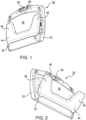
- This invention relates to a magnification device for individuals with low vision. More particularly, the present invention relates to a portable magnification device that has a variety of discrete configurations and that includes a camera, the position of which is reset depending upon the selected configuration of the device.
- US 2005/201047 discloses a portable computer.
- the portable computer includes a latch with a data capture device.
- the present disclosure relates to a magnification device with multiple orientations. This allows a blind or low vision user to select the best orientation for the task being performed.
- the device includes both opened and closed orientations. It is further configurable into document reading, near object viewing, far object viewing, and self inspection modes.
- the camera of the device can be manipulated by the user depending upon which of these orientations is selected. Furthermore, the camera automatically adjusts itself into one of two pre-set configurations whenever the device is opened or closed.
- the video camera (56) of the device (20) can be positioned by the user depending upon the task being performed.
- FIG. 2 illustrates the document viewing orientation wherein the camera (56) is pointed downwardly to view an object placed on the table.
- FIG. 4 illustrates a near object viewing orientation wherein camera (56) is angled to view object held in front of the camera (56) by the user.
- FIG. 3 illustrates the camera (56) in a self view mode. This allows the user to view themselves on monitor (42).
- camera (56) can be pointed to a distant object. This is the distant object viewing orientation.
- the user can readily manipulate the camera barrel (48) to orient camera (56) into one of these viewing orientations.
- camera (56) is automatically reset to the document viewing orientation ( FIG. 2 ) when the device (20) is opened. And camera (56) automatically resets into the distant object viewing orientation when device (20) is closed.
- the device (20) automatically resets to these positions via the interaction between brake, brake release, and stop mechanisms as elaborated upon hereinafter.
- Camera barrel (48) includes opposing axles (52) that allow the barrel (48) to be pivotally mounted within recess (32) of housing (22).
- Barrel (48) further includes a catch (54) that is positioned about one of the opposing axles (52). The function of this catch (54) is described in greater detail hereinafter.
- a video camera (56) is housed within the barrel (48).
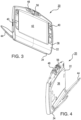
- barrel (48) has a document viewing orientation.
- Arrow B in FIG. 5 shows the near object viewing orientation of barrel (48).
- Arrow D in FIG. 6 shows the distant object viewing orientation of barrel (48).
- Arrow C in FIG. 5 and Arrow E of FIG. 6 show the self view orientation of barrel (48).
- the camera barrel (48) can be manipulated by the user into one of the foregoing orientations. This is accomplished by way of a brake mechanism (62). Brake mechanism ensures that once a desired angular orientation is selected, the barrel (48) will maintain that orientation. Brake mechanism (62) operates via the interaction of two spring forces. In particular, brake (62) counterbalances the force of the torsion spring (58). As illustrated in FIG. 8 , brake (62) is positioned within the interior (28) of the housing (22) and includes a band (64) with first and second ends (66 and 68). The first end (66) of the band (64) is fitted about one of the opposing axles (52) of the barrel (48). Band (64) is fitted about the axle at a point adjacent torsion spring (58).
- a coil spring (72) is then connected between the interior (28) of the housing (22) and the second end (68) of the band (64).
- the coil spring (72) is selected such that it can generate a sufficient force to fully counteract any rotational forces generated by torsion spring (58).
- Brake (62) has an engaged position where the force of the coil spring (72) is permitted to counterbalance the force of the torsion spring (58). This allows the angular orientation of the barrel (48) to be adjusted by hand.
- Brake (62) also has a disengaged position where the torsion spring (58) is permitted to rotate the barrel (48) into the forward most position. As explained below, this forward most position changes depending upon the operation of a stop mechanism.
- Brake release mechanism (74) operates by temporarily releasing the brake (62) and thereby allowing torsion spring to rotate barrel (48) to the forward most position.
- brake release mechanism (74) is positioned within the interior (28) of the housing (22) and includes a detent (76) within the hinge (34).
- Brake release mechanism (74) also includes a two bar linkage (78) that serves to interconnect the detent (76) and the band (64).
- the detent (76) causes the band (64) to cycle up and down, whereby the brake (62) is moved between the disengaged and engaged positions. This temporary disengagement of the brake permits the torsion spring (58) to reset the position of the barrel (48) to the forward most position.
- Stop mechanism (82) limits the forward most position of the barrel (48) depending upon whether the device (20) is in the opened or closed orientation.
- Stop mechanism (82) is positioned within the interior (28) of the housing (22) and includes a link (84) with a first end (86) and a second end (88).
- a lever (92) for moving the link (84) upwardly and downwardly is also positioned within the interior (28) of housing (22).
- One end of lever (92) extends through the front face (36) of the housing (22).
- Lever (92) is interconnected to the first end (86) of the link (84).
- the second end (88) of the link (84) is in contact with the catch (54) on the barrel (48).
Landscapes
- Engineering & Computer Science (AREA)
- Signal Processing (AREA)
- Multimedia (AREA)
- Educational Administration (AREA)
- Physics & Mathematics (AREA)
- Business, Economics & Management (AREA)
- Health & Medical Sciences (AREA)
- Educational Technology (AREA)
- General Physics & Mathematics (AREA)
- Theoretical Computer Science (AREA)
- General Health & Medical Sciences (AREA)
- Audiology, Speech & Language Pathology (AREA)
- Studio Devices (AREA)
- Camera Bodies And Camera Details Or Accessories (AREA)
- Accessories Of Cameras (AREA)
Claims (4)
- Dispositif d'agrandissement vidéo (20) comprenant :
un boîtier (22) comportant un bord supérieur (24), un bord inférieur (26), et un intérieur (28), un logement (32) formé à l'intérieur du bord supérieur (24), une charnière (34) positionnée le long du bord inférieur (26), le boîtier (22) ayant une face avant (36) et une face arrière (38), un écran vidéo (42) positionné dans la face arrière (38), le dispositif d'agrandissement vidéo comprenant également une base (44) avec deux pieds espacés (46), la base (44) étant connectée de manière pivotante au bord inférieur (26) du boîtier (22) au moyen de la charnière (34), de telle manière que la face avant (36) du boîtier (22) soit tournée vers la base (44), le dispositif (20) ayant une position ouverte et une position fermée, le boîtier (22) et la base (44) étant placés à un angle l'un par rapport à l'autre quand le dispositif (20) est dans la position ouverte, et le boîtier (22) et la base (44) étant en contact l'un avec l'autre quand le dispositif (20) est dans la position fermée, le dispositif d'agrandissement vidéo comprenant en outre :un barreau de caméra (48) avec des axes (52) opposés et alignés pour monter de manière pivotante le barreau (48) dans le renfoncement (32) du boîtier (22), une caméra vidéo (56) logée dans le barreau (48) et tournant avec celui-ci, la caméra vidéo (56) pouvant tourner entre la face avant (36) et la face arrière (38) du boîtier (22), le dispositif ayant une orientation de visualisation de document (A) dans laquelle le dispositif (20) est dans la position ouverte et la caméra vidéo (56) est orientée pour visualiser des objets positionnés vers la base (44), une orientation de visualisation d'objet proche (B) dans laquelle le dispositif (20) est dans la position ouverte et la caméra vidéo (56) est orientée pour visualiser des objets maintenus devant la face avant (36), et une orientation de visualisation d'objet distant (D) dans laquelle le dispositif (20) est dans la position fermée et la caméra vidéo (56) est orientée pour visualiser des objets à distance de la face avant (36), et une orientation d'auto-visualisation (C) dans laquelle le dispositif (20) est dans la position ouverte et la caméra vidéo (56) est orientée pour visualiser les objets devant la face arrière (38), le barreau (48) ayant une orientation angulaire différente dans chacune des différentes orientations ;un ressort de torsion (58) associé à l'un des axes (52) opposés du barreau de caméra (48), le ressort de torsion (58) fonctionnant pour faire tourner la caméra vidéo (56) vers la face avant (36) du boîtier (22) ; etun frein (62) pour contrebalancer la force du ressort de torsion (58), le frein (62) étant positionné à l'intérieur (28) du boîtier (22) et incluant une bande (64) avec une première extrémité (66) et une deuxième extrémité (68), la première extrémité (66) de la bande (64) étant fixée autour d'un des axes (52) opposés du barreau (48), un ressort hélicoïdal (72) étant connecté entre l'intérieur (28) du boîtier (22) et la deuxième extrémité (68) de la bande (64), le frein (62) ayant une position engagée où la force du ressort hélicoïdal (72) est autorisée à contrebalancer la force du ressort de torsion (58) pour permettre ainsi de régler manuellement l'orientation angulaire du barreau (48), le frein (62) ayant également une position désengagée où le ressort de torsion (58) est autorisé à faire tourner la caméra vidéo (56) vers la face avant (36) du boîtier (22). - Dispositif selon la revendication 1, comprenant en outre un mécanisme de desserrage de frein (74) pour desserrer temporairement le frein (62), le mécanisme de desserrage de frein (74) étant positionné à l'intérieur (28) du boîtier (22) et incluant une détente (76) à l'intérieur de la charnière (34) et une liaison à deux barres (78) interconnectant la détente (76) et la bande (64), de telle sorte que quand le dispositif (20) est dans la position ouverte ou dans la position fermée, la détente (76) amène la bande (64) à effectuer un cycle vers le haut et vers le bas, de telle sorte que le frein (62) est déplacé entre les positions désengagée et engagée et le ressort de torsion (58) est autorisé à faire tourner la caméra vidéo (56) vers la face avant du boîtier.
- Dispositif selon la revendication 2, comprenant en outre une butée (54) positionné autour de l'un des axes (52) opposés du barreau (48), et un mécanisme d'arrêt (82) pour limiter la position la plus en avant du barreau (48), le mécanisme d'arrêt (82) étant positionné à l'intérieur (28) du boîtier (22) et incluant une liaison (84) avec une première extrémité (86) et une deuxième extrémité (88), un levier (92) pour déplacer la liaison (84) vers le haut et vers le bas à l'intérieur (28) du boîtier (22), le levier (92) s'étendant à travers la face avant (36) du boîtier (22) et étant interconnecté avec la première extrémité (86) de la liaison (84), la deuxième extrémité (88) de la liaison (84) venant en contact avec la butée (54) sur le barreau (48), de telle sorte que quand le dispositif (20) est dans la position fermée, la base (44) entre en contact avec le levier (92) pour déplacer la liaison (84) vers le haut de telle manière que la position la plus en avant du barreau (48) soit limitée à l'orientation de visualisation d'objet distant, et de telle sorte que quand le dispositif (20) est dans la position ouverte, la liaison (84) se déplace vers le bas de telle manière que la caméra vidéo (56) soit orientée vers la base (44).
- Dispositif selon la revendication 3, comprenant en outre un amortisseur rotatif (94) associé au mécanisme de desserrage de frein (74), l'amortisseur rotatif (94) ralentissant le desserrage temporaire du frein (74) de telle manière que le barreau (48) ait suffisamment de temps pour faire tourner la caméra vidéo (56) vers la face avant (36) du boîtier.
Applications Claiming Priority (2)
| Application Number | Priority Date | Filing Date | Title |
|---|---|---|---|
| US201662300268P | 2016-02-26 | 2016-02-26 | |
| PCT/US2017/019341 WO2017147413A1 (fr) | 2016-02-26 | 2017-02-24 | Dispositif loupe à caméra réglable |
Publications (3)
| Publication Number | Publication Date |
|---|---|
| EP3420397A1 EP3420397A1 (fr) | 2019-01-02 |
| EP3420397A4 EP3420397A4 (fr) | 2019-12-04 |
| EP3420397B1 true EP3420397B1 (fr) | 2025-04-09 |
Family
ID=59679997
Family Applications (1)
| Application Number | Title | Priority Date | Filing Date |
|---|---|---|---|
| EP17757295.5A Active EP3420397B1 (fr) | 2016-02-26 | 2017-02-24 | Dispositif loupe à caméra réglable |
Country Status (4)
| Country | Link |
|---|---|
| US (2) | US10511749B2 (fr) |
| EP (1) | EP3420397B1 (fr) |
| JP (1) | JP6903679B2 (fr) |
| WO (1) | WO2017147413A1 (fr) |
Citations (1)
| Publication number | Priority date | Publication date | Assignee | Title |
|---|---|---|---|---|
| US20100026854A1 (en) * | 2008-08-04 | 2010-02-04 | Rodriguez Carlos M | Portable Multi Position Magnifier Camera |
Family Cites Families (53)
| Publication number | Priority date | Publication date | Assignee | Title |
|---|---|---|---|---|
| US3816646A (en) | 1972-08-24 | 1974-06-11 | Opaque Syst Ltd | Television enlarging and display apparatus for graphic copy |
| US4392732A (en) | 1981-12-28 | 1983-07-12 | Polaroid Corporation | Folding camera with viewfinder having independently mounted optical elements |
| US4387978A (en) * | 1981-12-28 | 1983-06-14 | Polaroid Corporation | Folding camera with pivotally mounted viewfinder |
| US5064426A (en) | 1987-12-11 | 1991-11-12 | Huebsch Donald L | Apparatus for removal of bone cement |
| US5734414A (en) * | 1994-03-03 | 1998-03-31 | Matsushita Electric Industrial Co., Ltd. | Camera apparatus for electronic conference |
| US6266045B1 (en) | 1994-06-30 | 2001-07-24 | Telxon Corporation | Interactive display user interface computer and method |
| JP3026273U (ja) | 1995-12-25 | 1996-07-02 | 株式会社ナイツ | 拡大読書器 |
| US6677936B2 (en) | 1996-10-31 | 2004-01-13 | Kopin Corporation | Color display system for a camera |
| US6064426A (en) | 1998-07-17 | 2000-05-16 | Waterman; Linden K. | Video magnification system |
| FI118073B (fi) | 2000-08-03 | 2007-06-15 | Nokia Corp | Kannettava, ainakin kaksi käyttöasentoa käsittävä taitettava elektroninen laite, sekä saranamekanismi sitä varten |
| USD454146S1 (en) | 2000-11-13 | 2002-03-05 | Matsushita Electric Industrial Co., Ltd. | Digital still camera |
| US20030089832A1 (en) | 2001-11-02 | 2003-05-15 | Gold Robert J. | Multi-function accessory for handheld electronics |
| US7359003B1 (en) | 2001-11-09 | 2008-04-15 | Synerdyne Corporation | Display, input and form factor for portable instruments |
| US7050106B2 (en) | 2001-11-21 | 2006-05-23 | Canon Kabushiki Kaisha | Image input device with rotatable image pickup unit |
| JP3773457B2 (ja) | 2002-03-07 | 2006-05-10 | 株式会社ミカミ | 携帯可能なテレビ式拡大表示装置 |
| US7259793B2 (en) | 2002-03-26 | 2007-08-21 | Eastman Kodak Company | Display module for supporting a digital image display device |
| US7295244B2 (en) | 2002-03-26 | 2007-11-13 | Eastman Kodak Company | System for capturing and archiving motion video segments |
| USD488440S1 (en) | 2003-01-21 | 2004-04-13 | Fuji Photo Film Co., Ltd. | Charger for digital cameras |
| US7583317B2 (en) | 2003-03-04 | 2009-09-01 | Sanyo Electric Co., Ltd. | Foldable electronic image pickup apparatus |
| JP3894902B2 (ja) | 2003-05-02 | 2007-03-22 | 株式会社ナイツ | 拡大読書器 |
| JP4225411B2 (ja) | 2003-06-06 | 2009-02-18 | 株式会社エルモ社 | 拡大読書器 |
| USD503944S1 (en) | 2003-06-17 | 2005-04-12 | Elmo Co., Ltd. | Video magnifier |
| GB2403370B (en) * | 2003-06-17 | 2007-04-25 | Ash Technologies Res Ltd | A viewing device |
| JP4230345B2 (ja) | 2003-12-09 | 2009-02-25 | 株式会社エルモ社 | 拡大読書器 |
| US7409147B2 (en) | 2004-01-30 | 2008-08-05 | Samsung Techwin Co., Ltd. | Video presenter with arch-type support |
| US7126816B2 (en) * | 2004-03-12 | 2006-10-24 | Apple Computer, Inc. | Camera latch |
| EP1745454A1 (fr) | 2004-04-13 | 2007-01-24 | Pulse Data International Limited | Loupe pour images destinee aux malvoyants |
| JP2005318177A (ja) | 2004-04-28 | 2005-11-10 | Elmo Co Ltd | 資料提示装置 |
| JP4429071B2 (ja) | 2004-05-12 | 2010-03-10 | Hoya株式会社 | カメラのグリップ回動進退軸構造及び回動進退軸構造 |
| JP4260072B2 (ja) | 2004-07-07 | 2009-04-30 | 株式会社ナイツ | 拡大読書器 |
| KR100660807B1 (ko) | 2004-12-08 | 2006-12-26 | 엘지.필립스 엘시디 주식회사 | 모바일단말기를 이용한 프로젝터어셈블리 |
| US7825949B2 (en) | 2005-03-09 | 2010-11-02 | Trulaske James A | Closed circuit video magnification system |
| JP4999279B2 (ja) | 2005-03-09 | 2012-08-15 | スカラ株式会社 | 拡大用アタッチメント |
| US8854442B2 (en) * | 2006-02-10 | 2014-10-07 | Freedom Scientific, Inc. | Retainer for electronic magnification device |
| US8854441B2 (en) | 2006-02-10 | 2014-10-07 | Freedom Scientific, Inc. | Electronic magnification device |
| JP2008005395A (ja) | 2006-06-26 | 2008-01-10 | Fujitsu Ltd | 携帯端末装置、携帯端末装置の制御装置、制御方法および制御プログラム |
| DE102006053652A1 (de) | 2006-11-13 | 2008-05-15 | Wolfgang Baum | Lesegerät |
| US9690168B2 (en) | 2006-11-20 | 2017-06-27 | Red.Com, Inc. | Focus assist system and method |
| US7929050B2 (en) | 2007-06-29 | 2011-04-19 | Epson America, Inc. | Document camera |
| KR100967128B1 (ko) * | 2007-11-23 | 2010-07-05 | 주식회사 힘스코리아 | 휴대형 영상 확대장치 |
| JP4985523B2 (ja) | 2008-03-31 | 2012-07-25 | 株式会社Jvcケンウッド | ビデオカメラ |
| JP5101544B2 (ja) | 2009-02-13 | 2012-12-19 | 富士通株式会社 | 撮影装置、撮影方法、撮影プログラム及び携帯端末装置 |
| US9213220B2 (en) | 2010-04-06 | 2015-12-15 | Youbiq, Llc | Camera control |
| JP5609561B2 (ja) | 2010-11-10 | 2014-10-22 | ソニー株式会社 | 投影装置 |
| NL2006698C2 (en) | 2011-04-29 | 2012-10-30 | Optelec Dev B V | Portable magnifying camera. |
| DE102011075273A1 (de) | 2011-05-04 | 2012-11-08 | Baum Retec Ag | Lesegerät |
| KR101817656B1 (ko) | 2011-12-13 | 2018-01-12 | 삼성전자주식회사 | 다기능 디스플레이를 구비하는 카메라 |
| US8681268B2 (en) | 2012-05-24 | 2014-03-25 | Abisee, Inc. | Vision assistive devices and user interfaces |
| US9992453B2 (en) * | 2012-07-20 | 2018-06-05 | Freedom Scientific, Inc. | Multiposition magnifier camera |
| US9154677B2 (en) | 2012-09-20 | 2015-10-06 | Apple Inc. | Camera accessory for angled camera viewing |
| US20140176690A1 (en) | 2012-12-21 | 2014-06-26 | Technologies Humanware Inc. | Magnification system |
| CO7130285A1 (es) | 2014-04-22 | 2014-12-01 | Diaz Arles Rodriguez | Equipo portable examinador de documentos con ayuda óptica 20x |
| JP6707522B2 (ja) | 2014-08-19 | 2020-06-10 | フリーダム サイエンティフィック インコーポレイテッド | ポータブル机上用ビデオ拡大機 |
-
2017
- 2017-02-24 EP EP17757295.5A patent/EP3420397B1/fr active Active
- 2017-02-24 JP JP2018544152A patent/JP6903679B2/ja active Active
- 2017-02-24 WO PCT/US2017/019341 patent/WO2017147413A1/fr not_active Ceased
- 2017-02-24 US US15/441,843 patent/US10511749B2/en active Active
-
2019
- 2019-12-17 US US16/716,667 patent/US11201990B2/en active Active
Patent Citations (1)
| Publication number | Priority date | Publication date | Assignee | Title |
|---|---|---|---|---|
| US20100026854A1 (en) * | 2008-08-04 | 2010-02-04 | Rodriguez Carlos M | Portable Multi Position Magnifier Camera |
Also Published As
| Publication number | Publication date |
|---|---|
| EP3420397A1 (fr) | 2019-01-02 |
| US10511749B2 (en) | 2019-12-17 |
| US20200128156A1 (en) | 2020-04-23 |
| EP3420397A4 (fr) | 2019-12-04 |
| US11201990B2 (en) | 2021-12-14 |
| JP2019512916A (ja) | 2019-05-16 |
| WO2017147413A1 (fr) | 2017-08-31 |
| JP6903679B2 (ja) | 2021-07-14 |
| US20170251133A1 (en) | 2017-08-31 |
Similar Documents
| Publication | Publication Date | Title |
|---|---|---|
| TWI598022B (zh) | 電子裝置及其樞軸機構 | |
| US9509816B2 (en) | Mobile phone adapting device and system | |
| JP6401381B2 (ja) | 保持装置及びそれを用いたリモートコントローラ | |
| EP3889664B1 (fr) | Loupe électronique pliable de type bureau | |
| JP2013088626A (ja) | 表示装置 | |
| US20070242150A1 (en) | Display apparatus and imaging device | |
| US11240438B1 (en) | Information handling system camera with automated tilt, pan and shutter functionality | |
| WO2015120297A1 (fr) | Systèmes de simplification de commande d'ordinateurs portables | |
| EP3420397B1 (fr) | Dispositif loupe à caméra réglable | |
| CN105407663B (zh) | 可携带式电子装置及其遮盖机构 | |
| WO2019024118A1 (fr) | Dispositif de commande à distance | |
| JP5296270B1 (ja) | ディジタルカメラ | |
| EP3328054A1 (fr) | Module de lentille | |
| JP6341567B2 (ja) | ヒンジ装置 | |
| JP5461739B1 (ja) | ディジタルカメラ | |
| TWI822084B (zh) | 雙用攝影機及使用其之攝影機模式影像調整方法 | |
| EP3259636B1 (fr) | Loupe de bureau articulée | |
| US20260032329A1 (en) | Variable field of view camera | |
| JP2020096252A (ja) | スマートフォンカバー | |
| CN209028391U (zh) | 电子装置 | |
| JP2017098722A (ja) | 電子機器 | |
| CN100342720C (zh) | 一种便携式终端的摄像头近摄调节装置 | |
| JP2018050227A (ja) | 回動装置、電子機器、及び撮像装置 | |
| US20060158625A1 (en) | Four-bar transmission mechanism | |
| CN2632719Y (zh) | 具旋转握把之数字影像撷取装置 |
Legal Events
| Date | Code | Title | Description |
|---|---|---|---|
| STAA | Information on the status of an ep patent application or granted ep patent |
Free format text: STATUS: THE INTERNATIONAL PUBLICATION HAS BEEN MADE |
|
| PUAI | Public reference made under article 153(3) epc to a published international application that has entered the european phase |
Free format text: ORIGINAL CODE: 0009012 |
|
| STAA | Information on the status of an ep patent application or granted ep patent |
Free format text: STATUS: REQUEST FOR EXAMINATION WAS MADE |
|
| 17P | Request for examination filed |
Effective date: 20180731 |
|
| AK | Designated contracting states |
Kind code of ref document: A1 Designated state(s): AL AT BE BG CH CY CZ DE DK EE ES FI FR GB GR HR HU IE IS IT LI LT LU LV MC MK MT NL NO PL PT RO RS SE SI SK SM TR |
|
| AX | Request for extension of the european patent |
Extension state: BA ME |
|
| DAV | Request for validation of the european patent (deleted) | ||
| DAX | Request for extension of the european patent (deleted) | ||
| RAP1 | Party data changed (applicant data changed or rights of an application transferred) |
Owner name: FREEDOM SCIENTIFIC, INC. |
|
| A4 | Supplementary search report drawn up and despatched |
Effective date: 20191104 |
|
| RIC1 | Information provided on ipc code assigned before grant |
Ipc: G03B 17/04 20060101ALI20191028BHEP Ipc: G03B 19/18 20060101ALI20191028BHEP Ipc: H04N 5/225 20060101ALI20191028BHEP Ipc: G02B 27/02 20060101AFI20191028BHEP |
|
| STAA | Information on the status of an ep patent application or granted ep patent |
Free format text: STATUS: EXAMINATION IS IN PROGRESS |
|
| 17Q | First examination report despatched |
Effective date: 20200708 |
|
| P01 | Opt-out of the competence of the unified patent court (upc) registered |
Effective date: 20230531 |
|
| GRAP | Despatch of communication of intention to grant a patent |
Free format text: ORIGINAL CODE: EPIDOSNIGR1 |
|
| STAA | Information on the status of an ep patent application or granted ep patent |
Free format text: STATUS: GRANT OF PATENT IS INTENDED |
|
| RIC1 | Information provided on ipc code assigned before grant |
Ipc: H04N 23/57 20230101ALI20241016BHEP Ipc: H04N 23/51 20230101ALI20241016BHEP Ipc: G09B 21/00 20060101ALI20241016BHEP Ipc: G03B 19/18 20060101ALI20241016BHEP Ipc: G03B 17/04 20060101ALI20241016BHEP Ipc: G02B 27/02 20060101AFI20241016BHEP |
|
| INTG | Intention to grant announced |
Effective date: 20241104 |
|
| GRAS | Grant fee paid |
Free format text: ORIGINAL CODE: EPIDOSNIGR3 |
|
| GRAA | (expected) grant |
Free format text: ORIGINAL CODE: 0009210 |
|
| STAA | Information on the status of an ep patent application or granted ep patent |
Free format text: STATUS: THE PATENT HAS BEEN GRANTED |
|
| AK | Designated contracting states |
Kind code of ref document: B1 Designated state(s): AL AT BE BG CH CY CZ DE DK EE ES FI FR GB GR HR HU IE IS IT LI LT LU LV MC MK MT NL NO PL PT RO RS SE SI SK SM TR |
|
| REG | Reference to a national code |
Ref country code: GB Ref legal event code: FG4D |
|
| REG | Reference to a national code |
Ref country code: CH Ref legal event code: EP |
|
| REG | Reference to a national code |
Ref country code: DE Ref legal event code: R096 Ref document number: 602017088818 Country of ref document: DE |
|
| REG | Reference to a national code |
Ref country code: IE Ref legal event code: FG4D |
|
| REG | Reference to a national code |
Ref country code: NL Ref legal event code: FP |
|
| REG | Reference to a national code |
Ref country code: DE Ref legal event code: R081 Ref document number: 602017088818 Country of ref document: DE Owner name: ENHANCED VISION SYSTEMS, INC., CLEARWATER, US Free format text: FORMER OWNER: FREEDOM SCIENTIFIC, INC., CLEARWATER, FL, US |
|
| RAP2 | Party data changed (patent owner data changed or rights of a patent transferred) |
Owner name: ENHANCED VISION SYSTEMS, INC. |
|
| REG | Reference to a national code |
Ref country code: AT Ref legal event code: MK05 Ref document number: 1784041 Country of ref document: AT Kind code of ref document: T Effective date: 20250409 |
|
| PG25 | Lapsed in a contracting state [announced via postgrant information from national office to epo] |
Ref country code: FI Free format text: LAPSE BECAUSE OF FAILURE TO SUBMIT A TRANSLATION OF THE DESCRIPTION OR TO PAY THE FEE WITHIN THE PRESCRIBED TIME-LIMIT Effective date: 20250409 Ref country code: ES Free format text: LAPSE BECAUSE OF FAILURE TO SUBMIT A TRANSLATION OF THE DESCRIPTION OR TO PAY THE FEE WITHIN THE PRESCRIBED TIME-LIMIT Effective date: 20250409 Ref country code: PT Free format text: LAPSE BECAUSE OF FAILURE TO SUBMIT A TRANSLATION OF THE DESCRIPTION OR TO PAY THE FEE WITHIN THE PRESCRIBED TIME-LIMIT Effective date: 20250811 |
|
| REG | Reference to a national code |
Ref country code: LT Ref legal event code: MG9D |
|
| PG25 | Lapsed in a contracting state [announced via postgrant information from national office to epo] |
Ref country code: NO Free format text: LAPSE BECAUSE OF FAILURE TO SUBMIT A TRANSLATION OF THE DESCRIPTION OR TO PAY THE FEE WITHIN THE PRESCRIBED TIME-LIMIT Effective date: 20250709 Ref country code: GR Free format text: LAPSE BECAUSE OF FAILURE TO SUBMIT A TRANSLATION OF THE DESCRIPTION OR TO PAY THE FEE WITHIN THE PRESCRIBED TIME-LIMIT Effective date: 20250710 |
|
| PG25 | Lapsed in a contracting state [announced via postgrant information from national office to epo] |
Ref country code: PL Free format text: LAPSE BECAUSE OF FAILURE TO SUBMIT A TRANSLATION OF THE DESCRIPTION OR TO PAY THE FEE WITHIN THE PRESCRIBED TIME-LIMIT Effective date: 20250409 |
|
| PG25 | Lapsed in a contracting state [announced via postgrant information from national office to epo] |
Ref country code: BG Free format text: LAPSE BECAUSE OF FAILURE TO SUBMIT A TRANSLATION OF THE DESCRIPTION OR TO PAY THE FEE WITHIN THE PRESCRIBED TIME-LIMIT Effective date: 20250409 |
|
| PG25 | Lapsed in a contracting state [announced via postgrant information from national office to epo] |
Ref country code: HR Free format text: LAPSE BECAUSE OF FAILURE TO SUBMIT A TRANSLATION OF THE DESCRIPTION OR TO PAY THE FEE WITHIN THE PRESCRIBED TIME-LIMIT Effective date: 20250409 |
|
| PG25 | Lapsed in a contracting state [announced via postgrant information from national office to epo] |
Ref country code: AT Free format text: LAPSE BECAUSE OF FAILURE TO SUBMIT A TRANSLATION OF THE DESCRIPTION OR TO PAY THE FEE WITHIN THE PRESCRIBED TIME-LIMIT Effective date: 20250409 |
|
| PG25 | Lapsed in a contracting state [announced via postgrant information from national office to epo] |
Ref country code: RS Free format text: LAPSE BECAUSE OF FAILURE TO SUBMIT A TRANSLATION OF THE DESCRIPTION OR TO PAY THE FEE WITHIN THE PRESCRIBED TIME-LIMIT Effective date: 20250709 |
|
| PG25 | Lapsed in a contracting state [announced via postgrant information from national office to epo] |
Ref country code: IS Free format text: LAPSE BECAUSE OF FAILURE TO SUBMIT A TRANSLATION OF THE DESCRIPTION OR TO PAY THE FEE WITHIN THE PRESCRIBED TIME-LIMIT Effective date: 20250809 |
|
| PG25 | Lapsed in a contracting state [announced via postgrant information from national office to epo] |
Ref country code: LV Free format text: LAPSE BECAUSE OF FAILURE TO SUBMIT A TRANSLATION OF THE DESCRIPTION OR TO PAY THE FEE WITHIN THE PRESCRIBED TIME-LIMIT Effective date: 20250409 |
|
| REG | Reference to a national code |
Ref country code: DE Ref legal event code: R097 Ref document number: 602017088818 Country of ref document: DE |
|
| PG25 | Lapsed in a contracting state [announced via postgrant information from national office to epo] |
Ref country code: DK Free format text: LAPSE BECAUSE OF FAILURE TO SUBMIT A TRANSLATION OF THE DESCRIPTION OR TO PAY THE FEE WITHIN THE PRESCRIBED TIME-LIMIT Effective date: 20250409 Ref country code: SM Free format text: LAPSE BECAUSE OF FAILURE TO SUBMIT A TRANSLATION OF THE DESCRIPTION OR TO PAY THE FEE WITHIN THE PRESCRIBED TIME-LIMIT Effective date: 20250409 |
|
| PG25 | Lapsed in a contracting state [announced via postgrant information from national office to epo] |
Ref country code: CZ Free format text: LAPSE BECAUSE OF FAILURE TO SUBMIT A TRANSLATION OF THE DESCRIPTION OR TO PAY THE FEE WITHIN THE PRESCRIBED TIME-LIMIT Effective date: 20250409 |
|
| PG25 | Lapsed in a contracting state [announced via postgrant information from national office to epo] |
Ref country code: EE Free format text: LAPSE BECAUSE OF FAILURE TO SUBMIT A TRANSLATION OF THE DESCRIPTION OR TO PAY THE FEE WITHIN THE PRESCRIBED TIME-LIMIT Effective date: 20250409 |
|
| PG25 | Lapsed in a contracting state [announced via postgrant information from national office to epo] |
Ref country code: SK Free format text: LAPSE BECAUSE OF FAILURE TO SUBMIT A TRANSLATION OF THE DESCRIPTION OR TO PAY THE FEE WITHIN THE PRESCRIBED TIME-LIMIT Effective date: 20250409 Ref country code: RO Free format text: LAPSE BECAUSE OF FAILURE TO SUBMIT A TRANSLATION OF THE DESCRIPTION OR TO PAY THE FEE WITHIN THE PRESCRIBED TIME-LIMIT Effective date: 20250409 |
|
| PG25 | Lapsed in a contracting state [announced via postgrant information from national office to epo] |
Ref country code: IT Free format text: LAPSE BECAUSE OF FAILURE TO SUBMIT A TRANSLATION OF THE DESCRIPTION OR TO PAY THE FEE WITHIN THE PRESCRIBED TIME-LIMIT Effective date: 20250409 |
|
| PLBE | No opposition filed within time limit |
Free format text: ORIGINAL CODE: 0009261 |
|
| STAA | Information on the status of an ep patent application or granted ep patent |
Free format text: STATUS: NO OPPOSITION FILED WITHIN TIME LIMIT |
|
| REG | Reference to a national code |
Ref country code: CH Ref legal event code: L10 Free format text: ST27 STATUS EVENT CODE: U-0-0-L10-L00 (AS PROVIDED BY THE NATIONAL OFFICE) Effective date: 20260218 |
|
| PGFP | Annual fee paid to national office [announced via postgrant information from national office to epo] |
Ref country code: NL Payment date: 20260218 Year of fee payment: 10 |
|
| 26N | No opposition filed |
Effective date: 20260112 |