EP3420397B1 - Magnifier device with adjustable camera - Google Patents
Magnifier device with adjustable camera Download PDFInfo
- Publication number
- EP3420397B1 EP3420397B1 EP17757295.5A EP17757295A EP3420397B1 EP 3420397 B1 EP3420397 B1 EP 3420397B1 EP 17757295 A EP17757295 A EP 17757295A EP 3420397 B1 EP3420397 B1 EP 3420397B1
- Authority
- EP
- European Patent Office
- Prior art keywords
- housing
- barrel
- brake
- video camera
- front face
- Prior art date
- Legal status (The legal status is an assumption and is not a legal conclusion. Google has not performed a legal analysis and makes no representation as to the accuracy of the status listed.)
- Active
Links
Images


Classifications
-
- G—PHYSICS
- G09—EDUCATION; CRYPTOGRAPHY; DISPLAY; ADVERTISING; SEALS
- G09B—EDUCATIONAL OR DEMONSTRATION APPLIANCES; APPLIANCES FOR TEACHING, OR COMMUNICATING WITH, THE BLIND, DEAF OR MUTE; MODELS; PLANETARIA; GLOBES; MAPS; DIAGRAMS
- G09B21/00—Teaching, or communicating with, the blind, deaf or mute
- G09B21/001—Teaching or communicating with blind persons
- G09B21/008—Teaching or communicating with blind persons using visual presentation of the information for the partially sighted
-
- H—ELECTRICITY
- H04—ELECTRIC COMMUNICATION TECHNIQUE
- H04N—PICTORIAL COMMUNICATION, e.g. TELEVISION
- H04N23/00—Cameras or camera modules comprising electronic image sensors; Control thereof
- H04N23/50—Constructional details
- H04N23/51—Housings
-
- H—ELECTRICITY
- H04—ELECTRIC COMMUNICATION TECHNIQUE
- H04N—PICTORIAL COMMUNICATION, e.g. TELEVISION
- H04N23/00—Cameras or camera modules comprising electronic image sensors; Control thereof
- H04N23/57—Mechanical or electrical details of cameras or camera modules specially adapted for being embedded in other devices
-
- H—ELECTRICITY
- H04—ELECTRIC COMMUNICATION TECHNIQUE
- H04N—PICTORIAL COMMUNICATION, e.g. TELEVISION
- H04N23/00—Cameras or camera modules comprising electronic image sensors; Control thereof
- H04N23/60—Control of cameras or camera modules
- H04N23/69—Control of means for changing angle of the field of view, e.g. optical zoom objectives or electronic zooming
Definitions
- This invention relates to a magnification device for individuals with low vision. More particularly, the present invention relates to a portable magnification device that has a variety of discrete configurations and that includes a camera, the position of which is reset depending upon the selected configuration of the device.
- US 2005/201047 discloses a portable computer.
- the portable computer includes a latch with a data capture device.
- the present disclosure relates to a magnification device with multiple orientations. This allows a blind or low vision user to select the best orientation for the task being performed.
- the device includes both opened and closed orientations. It is further configurable into document reading, near object viewing, far object viewing, and self inspection modes.
- the camera of the device can be manipulated by the user depending upon which of these orientations is selected. Furthermore, the camera automatically adjusts itself into one of two pre-set configurations whenever the device is opened or closed.
- the video camera (56) of the device (20) can be positioned by the user depending upon the task being performed.
- FIG. 2 illustrates the document viewing orientation wherein the camera (56) is pointed downwardly to view an object placed on the table.
- FIG. 4 illustrates a near object viewing orientation wherein camera (56) is angled to view object held in front of the camera (56) by the user.
- FIG. 3 illustrates the camera (56) in a self view mode. This allows the user to view themselves on monitor (42).
- camera (56) can be pointed to a distant object. This is the distant object viewing orientation.
- the user can readily manipulate the camera barrel (48) to orient camera (56) into one of these viewing orientations.
- camera (56) is automatically reset to the document viewing orientation ( FIG. 2 ) when the device (20) is opened. And camera (56) automatically resets into the distant object viewing orientation when device (20) is closed.
- the device (20) automatically resets to these positions via the interaction between brake, brake release, and stop mechanisms as elaborated upon hereinafter.
- Camera barrel (48) includes opposing axles (52) that allow the barrel (48) to be pivotally mounted within recess (32) of housing (22).
- Barrel (48) further includes a catch (54) that is positioned about one of the opposing axles (52). The function of this catch (54) is described in greater detail hereinafter.
- a video camera (56) is housed within the barrel (48).
- barrel (48) has a document viewing orientation.
- Arrow B in FIG. 5 shows the near object viewing orientation of barrel (48).
- Arrow D in FIG. 6 shows the distant object viewing orientation of barrel (48).
- Arrow C in FIG. 5 and Arrow E of FIG. 6 show the self view orientation of barrel (48).
- the camera barrel (48) can be manipulated by the user into one of the foregoing orientations. This is accomplished by way of a brake mechanism (62). Brake mechanism ensures that once a desired angular orientation is selected, the barrel (48) will maintain that orientation. Brake mechanism (62) operates via the interaction of two spring forces. In particular, brake (62) counterbalances the force of the torsion spring (58). As illustrated in FIG. 8 , brake (62) is positioned within the interior (28) of the housing (22) and includes a band (64) with first and second ends (66 and 68). The first end (66) of the band (64) is fitted about one of the opposing axles (52) of the barrel (48). Band (64) is fitted about the axle at a point adjacent torsion spring (58).
- a coil spring (72) is then connected between the interior (28) of the housing (22) and the second end (68) of the band (64).
- the coil spring (72) is selected such that it can generate a sufficient force to fully counteract any rotational forces generated by torsion spring (58).
- Brake (62) has an engaged position where the force of the coil spring (72) is permitted to counterbalance the force of the torsion spring (58). This allows the angular orientation of the barrel (48) to be adjusted by hand.
- Brake (62) also has a disengaged position where the torsion spring (58) is permitted to rotate the barrel (48) into the forward most position. As explained below, this forward most position changes depending upon the operation of a stop mechanism.
- Brake release mechanism (74) operates by temporarily releasing the brake (62) and thereby allowing torsion spring to rotate barrel (48) to the forward most position.
- brake release mechanism (74) is positioned within the interior (28) of the housing (22) and includes a detent (76) within the hinge (34).
- Brake release mechanism (74) also includes a two bar linkage (78) that serves to interconnect the detent (76) and the band (64).
- the detent (76) causes the band (64) to cycle up and down, whereby the brake (62) is moved between the disengaged and engaged positions. This temporary disengagement of the brake permits the torsion spring (58) to reset the position of the barrel (48) to the forward most position.
- Stop mechanism (82) limits the forward most position of the barrel (48) depending upon whether the device (20) is in the opened or closed orientation.
- Stop mechanism (82) is positioned within the interior (28) of the housing (22) and includes a link (84) with a first end (86) and a second end (88).
- a lever (92) for moving the link (84) upwardly and downwardly is also positioned within the interior (28) of housing (22).
- One end of lever (92) extends through the front face (36) of the housing (22).
- Lever (92) is interconnected to the first end (86) of the link (84).
- the second end (88) of the link (84) is in contact with the catch (54) on the barrel (48).
Landscapes
- Engineering & Computer Science (AREA)
- Signal Processing (AREA)
- Multimedia (AREA)
- Educational Administration (AREA)
- Physics & Mathematics (AREA)
- Business, Economics & Management (AREA)
- Health & Medical Sciences (AREA)
- Educational Technology (AREA)
- General Physics & Mathematics (AREA)
- Theoretical Computer Science (AREA)
- General Health & Medical Sciences (AREA)
- Audiology, Speech & Language Pathology (AREA)
- Studio Devices (AREA)
- Camera Bodies And Camera Details Or Accessories (AREA)
- Accessories Of Cameras (AREA)
Description
- This invention relates to a magnification device for individuals with low vision. More particularly, the present invention relates to a portable magnification device that has a variety of discrete configurations and that includes a camera, the position of which is reset depending upon the selected configuration of the device.
- The use of portable magnifiers for low vision users is known in the art. To date, however, these magnifiers have been heavy, bulky, and cumbersome to use. Additionally, many of these magnifiers have only one mode of operation, a mode that requires the user to hold the device at a fixed distance above the object being viewed.
- Additionally, many magnifiers that are designed to be placed upon the object to be viewed typically leave little or no room over top of the object. This prohibits the user from interacting with the object being viewed. For instance, if the object is a document, a user cannot write upon the document while it is being magnified.
- What is needed, then, is a magnifier with multiple configurations and modes of operation, whereby a user can use the magnifier by either holding the device over the object or by placing the device upon the object. There is an additional need for a magnifier that allows users to interact with the object while it is being magnified. There is also a need in the art for a portable magnifier that has a compact closed orientation that protects the magnifier when it is not in use.
-
US 2005/062847 discloses a viewing device that includes a camera for capturing a visual image of text on a page. The camera is pivotally movable between reading and writing orientations. -
US 2014/022364 discloses a multiposition magnifier camera that can be positioned into a variety of different configurations. The device includes a pivotal handle. -
US 2005/201047 discloses a portable computer. The portable computer includes a latch with a data capture device. - There is a further need in the art for a magnification device with a camera that is automatically adjusted in response to the selected configuration of the device.
- It is an object of the present disclosure to provide a magnification device with a number of discrete orientations.
- It is a further object of the present disclosure to provide a magnification device with a variety of different orientations with the user selecting the desired orientation depending upon the intended use of the magnification device.
- It is therefore one of the objectives of this invention to allow a user to configure a magnifier camera that can either be held over an object to be viewed or positioned upon the object to be viewed.
- It is a further object of the present disclosure to provide a magnification device with a camera that orients itself automatically depending upon the selected configuration of the device.
- The invention is set out in the appended set of claims.
- For a more complete understanding of the present disclosure and its advantages, reference is now made to the following descriptions, taken in conjunction with the accompanying drawings, in which:
-
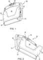
FIG. 1 is a perspective view of the magnification device in the distant object viewing orientation. -
FIG. 2 is a perspective view of the magnification device in the document viewing orientation. -
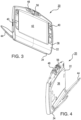
FIG. 3 is a perspective view of the magnification device in the self viewing orientation. -
FIG. 4 is a perspective view of the magnification device in the near object viewing orientation. -
FIG. 5 is a side elevational view of the magnification device in the opened orientation and showing the document viewing camera orientation (A), the near object viewing camera orientation (B), and the self viewing camera orientation (C). -
FIG. 6 is a side elevational view of the magnification device in the closed orientation and showing the distant object camera viewing orientation (D) and self viewing camera orientation (E). -
FIG. 7 is a detailed view of the camera barrel assembly. -
FIG. 8 is a view of the internal components of the housing of the magnification device. -
FIG. 9 is an exploded view of the internal components of the housing of the magnification device. - Similar reference numerals refer to similar parts throughout the several views of the drawings.
- The present disclosure relates to a magnification device with multiple orientations. This allows a blind or low vision user to select the best orientation for the task being performed. The device includes both opened and closed orientations. It is further configurable into document reading, near object viewing, far object viewing, and self inspection modes. The camera of the device can be manipulated by the user depending upon which of these orientations is selected. Furthermore, the camera automatically adjusts itself into one of two pre-set configurations whenever the device is opened or closed. The various components of the preset disclosure, and the manner in which they interrelate, are described in greater detail hereinafter.
-
FIGS. 1-6 illustrate the various configurations of the magnification device (20) of the present disclosure.FIGS. 1 and6 illustrate the device (20) in the closed orientation with the housing (22) and base (44) in facing relation with one another. This allows the device to be held by the user.FIGS. 2 ,3 ,4 , and5 illustrate the device (20) in the opened orientation with the housing (22) and base (44) pivoted away from one another. This permits the device (20) to be placed on a table or other surface. - The video camera (56) of the device (20) can be positioned by the user depending upon the task being performed.
FIG. 2 illustrates the document viewing orientation wherein the camera (56) is pointed downwardly to view an object placed on the table.FIG. 4 illustrates a near object viewing orientation wherein camera (56) is angled to view object held in front of the camera (56) by the user.FIG. 3 illustrates the camera (56) in a self view mode. This allows the user to view themselves on monitor (42). Finally, when in the closed orientation, camera (56) can be pointed to a distant object. This is the distant object viewing orientation. As explained hereinafter, the user can readily manipulate the camera barrel (48) to orient camera (56) into one of these viewing orientations. However, in accordance with the disclosure, camera (56) is automatically reset to the document viewing orientation (FIG. 2 ) when the device (20) is opened. And camera (56) automatically resets into the distant object viewing orientation when device (20) is closed. The device (20) automatically resets to these positions via the interaction between brake, brake release, and stop mechanisms as elaborated upon hereinafter. -
FIG. 8 is a detailed view of housing (22) and shows the top edge (24), a bottom edge (26), and an interior (28) of the housing (22). As illustrated, housing (22) includes a recess (32) formed within the top edge (24). A hinge (34) is positioned along the bottom edge (26). Housing (22) is further defined by a front face (36) and a back face (38). A video screen (42) is positioned within the back face (38). Video screen (42) permits the user to view images of objects taken by camera (56). A video processor (not shown) can be included within the interior (28) of housing (22). As in known in the art, video processor allows the images taken by camera (56) to be greatly enlarged to assist viewing by blind or low vision users. - Housing (22) includes a pivotally attached base (44). Base (44) includes two spaced apart feet (46). This creates an intervening space where objects to be view can be placed. Base (44) is pivotally connected to the bottom edge (26) of the housing (22) by way of the hinge (34). Device (20) thus has first and second orientations. In the first (or opened) orientation, housing (22) and base (44) are at an angle with respect to one another. This angle can range from less than 90 degrees to greater than 10 degrees. This configuration allows base (44) to rest upon a surface, such as a table or desk. The angular position of housing (22) is chosen to suit the viewing needs of the user. In the second (or closed) orientation, housing (22) and base (44) are in contact with one another. This is also known as the hand held mode, as this configuration allows device (20) to be more easily manipulated by the user.
- The camera barrel (48) is next described in connection with
FIG. 7 . Camera barrel (48) includes opposing axles (52) that allow the barrel (48) to be pivotally mounted within recess (32) of housing (22). Barrel (48) further includes a catch (54) that is positioned about one of the opposing axles (52). The function of this catch (54) is described in greater detail hereinafter. A video camera (56) is housed within the barrel (48). As noted by Arrow A inFIG. 5 , barrel (48) has a document viewing orientation. Arrow B inFIG. 5 shows the near object viewing orientation of barrel (48). Arrow D inFIG. 6 shows the distant object viewing orientation of barrel (48). Finally, Arrow C inFIG. 5 and Arrow E ofFIG. 6 show the self view orientation of barrel (48). Thus, barrel (48) has a different angular orientation in each of the different viewing orientations. Barrel (48) includes a torsion spring (58) associated with one of the opposing axles (52). This torsion spring (58) functions to initially rotate the barrel (48) into a forward most position. If the device (20) is opened, this forward most position corresponds to the document view orientation, and if device (20) is closed this forward most position correspond to the distant object viewing orientation. - The camera barrel (48) can be manipulated by the user into one of the foregoing orientations. This is accomplished by way of a brake mechanism (62). Brake mechanism ensures that once a desired angular orientation is selected, the barrel (48) will maintain that orientation. Brake mechanism (62) operates via the interaction of two spring forces. In particular, brake (62) counterbalances the force of the torsion spring (58). As illustrated in
FIG. 8 , brake (62) is positioned within the interior (28) of the housing (22) and includes a band (64) with first and second ends (66 and 68). The first end (66) of the band (64) is fitted about one of the opposing axles (52) of the barrel (48). Band (64) is fitted about the axle at a point adjacent torsion spring (58). A coil spring (72) is then connected between the interior (28) of the housing (22) and the second end (68) of the band (64). The coil spring (72) is selected such that it can generate a sufficient force to fully counteract any rotational forces generated by torsion spring (58). Brake (62) has an engaged position where the force of the coil spring (72) is permitted to counterbalance the force of the torsion spring (58). This allows the angular orientation of the barrel (48) to be adjusted by hand. Brake (62) also has a disengaged position where the torsion spring (58) is permitted to rotate the barrel (48) into the forward most position. As explained below, this forward most position changes depending upon the operation of a stop mechanism. - The brake release mechanism (74) is next described in connection with
FIG. 8 . Brake release mechanism (74) operates by temporarily releasing the brake (62) and thereby allowing torsion spring to rotate barrel (48) to the forward most position. As illustrated, brake release mechanism (74) is positioned within the interior (28) of the housing (22) and includes a detent (76) within the hinge (34). Brake release mechanism (74) also includes a two bar linkage (78) that serves to interconnect the detent (76) and the band (64). In use, as device (20) is moved into either the opened or closed orientations, the detent (76) causes the band (64) to cycle up and down, whereby the brake (62) is moved between the disengaged and engaged positions. This temporary disengagement of the brake permits the torsion spring (58) to reset the position of the barrel (48) to the forward most position. - The forward most position of the barrel (48) is determined via the operation of a stop mechanism (82). More specifically, stop mechanism (82) limits the forward most position of the barrel (48) depending upon whether the device (20) is in the opened or closed orientation. Stop mechanism (82) is positioned within the interior (28) of the housing (22) and includes a link (84) with a first end (86) and a second end (88). A lever (92) for moving the link (84) upwardly and downwardly is also positioned within the interior (28) of housing (22). One end of lever (92) extends through the front face (36) of the housing (22). Lever (92) is interconnected to the first end (86) of the link (84). The second end (88) of the link (84) is in contact with the catch (54) on the barrel (48). As such, when the device (20) is in the second, or closed, orientation the base (44) contacts the lever (92) to shift the link (84) upwardly. This upward movement of the link, in turn, ensures that the forward most position of the barrel (48) is limited to the distant object viewing orientation. Alternatively, when the device (20) is in the first, or opened, orientation the link (84) shifts downwardly such that the forward most position of the barrel (48) is limited to the document viewing orientation. In this manner, when device (20) is initially opened, camera (56) is initially oriented (or reset) into the document viewing mode. And when device (20) is initially closed, camera (56) is initially oriented (or reset) into the distant object viewing orientation. In either case, the user is subsequently able to manipulate camera barrel (48) into another viewing orientation. However, the resetting of the camera (56) as described ensures the blind or low vision user does not become disoriented when configuring the device (20).
- Finally, a rotatory damper (94) is optionally associated with the brake release mechanism (74). The rotatory damper (94) functions by slowing the temporary release of the brake (74). This, in turn, ensures that barrel (48) has sufficient time to achieve the forward most position before the brake is reengaged.
Claims (4)
- A video magnification device (20) comprising:
a housing (22) having a top edge (24), a bottom edge (26), and an interior (28), a recess (32) formed within the top edge (24), a hinge (34) positioned along the bottom edge (26), the housing (22) having a front face (36) and a back face (38), a video screen (42) positioned within the back face (38), the video magnification device also comprising a base (44) with two spaced apart feet (46), the base (44) pivotally connected to the bottom edge (26) of the housing (22) by way of the hinge (34), such that the front face (36) of housing (22) faces the base (44), the device (20) having an open position and a closed position, the housing (22) and base (44) being at an angle with respect to one another when the device (20) is in the opened position and the housing (22) and base (44) being in contact with one another when the device (20) is in the closed position, the video magnification device further comprising:a camera barrel (48) with opposing and aligned axles (52) for pivotally mounting the barrel (48) within the recess (32) of the housing (22), a video camera (56) housed within and rotating with the barrel (48), the video camera (56) being rotatable between the front face (36) and back face (38) of the housing (22), the device having a document viewing orientation (A), wherein the device (20) is in the opened position and the video camera (56) is oriented to view objects positioned toward the base (44), a near object viewing orientation (B) wherein the device (20) is in the opened position and the video camera (56) is oriented to view objects held before the front face (36), and a distant object viewing orientation (D) wherein the device (20) is in the closed position and the video camera (56) is oriented to view objects at a distance from the front face (36), and a self-view orientation (C) wherein the device (20) is in the opened position and the video camera (56) is oriented to view objects in front of the back face (38) the barrel (48) having a different angular orientation in each of the different orientations;a torsion spring (58) associated with one of the opposing axles (52) of the camera barrel (48), the torsion spring (58) functioning to rotate the video camera (56) towards the front face (36) of the housing (22); anda brake (62) for counterbalancing the force of the torsion spring (58), the brake (62) positioned within the interior (28) of the housing (22) and including a band (64) with a first end (66) and a second end (68), the first end (66) of the band (64) fitted about one of the opposing axles (52) of the barrel (48), a coil spring (72) connected between the interior (28) of the housing (22) and the second end (68) of the band (64), the brake (62) having an engaged position where the force of the coil spring (72) is permitted to counterbalance the force of the torsion spring (58) to thereby allow the angular orientation of the barrel (48) to be adjusted by hand, the brake (62) also having a disengaged position where the torsion spring (58) is permitted to rotate the video camera (56) towards the front face (36) of the housing (22). - The device as described in Claim 1, further comprising a brake release mechanism (74) for temporarily releasing the brake (62), the brake release mechanism (74) positioned within the interior (28) of the housing (22) and including a detent (76) within the hinge (34) and a two bar linkage (78) interconnecting the detent (76) and the band (64), whereby when the device (20) is in the opened position or the closed position the detent (76) causes the band (64) to cycle up and down, whereby the brake (62) is moved between the disengaged and engaged positions and the torsion spring (58) is permitted to rotate the video camera (56) towards the front face of the housing.
- The device as described in Claim 2, further comprising a catch (54) positioned about one of the opposing axles (52) of the barrel (48), and a stop mechanism (82) for limiting the forward most position of the barrel (48), the stop mechanism (82) positioned within the interior (28) of the housing (22) and including a link (84) with a first end (86) and a second end (88), a lever (92) for moving the link (84) upwardly and downwardly within the interior (28) of housing (22), the lever (92) extending through the front face (36) of the housing (22) and interconnected to the first end (86) of the link (84), the second end (88) of the link (84) contacting the catch (54) on the barrel (48), whereby when the device (20) is in the closed position the base (44) contacts the lever (92) to shift the link (84) upwardly such that the forward most position of the barrel (48) is limited to the distant object viewing orientation, and whereby when the device (20) is in the opened position the link (84) shifts downwardly such that the video camera (56) is oriented towards the base (44).
- The device as described in Claim 3, further comprising a rotatory damper (94) associated with the brake release mechanism (74), the rotatory damper (94) slowing the temporary release of the brake (74) such that the barrel (48) has sufficient time rotate the video camera (56) towards the front face (36) of the housing.
Applications Claiming Priority (2)
| Application Number | Priority Date | Filing Date | Title |
|---|---|---|---|
| US201662300268P | 2016-02-26 | 2016-02-26 | |
| PCT/US2017/019341 WO2017147413A1 (en) | 2016-02-26 | 2017-02-24 | Magnifier device with adjustable camera |
Publications (3)
| Publication Number | Publication Date |
|---|---|
| EP3420397A1 EP3420397A1 (en) | 2019-01-02 |
| EP3420397A4 EP3420397A4 (en) | 2019-12-04 |
| EP3420397B1 true EP3420397B1 (en) | 2025-04-09 |
Family
ID=59679997
Family Applications (1)
| Application Number | Title | Priority Date | Filing Date |
|---|---|---|---|
| EP17757295.5A Active EP3420397B1 (en) | 2016-02-26 | 2017-02-24 | Magnifier device with adjustable camera |
Country Status (4)
| Country | Link |
|---|---|
| US (2) | US10511749B2 (en) |
| EP (1) | EP3420397B1 (en) |
| JP (1) | JP6903679B2 (en) |
| WO (1) | WO2017147413A1 (en) |
Citations (1)
| Publication number | Priority date | Publication date | Assignee | Title |
|---|---|---|---|---|
| US20100026854A1 (en) * | 2008-08-04 | 2010-02-04 | Rodriguez Carlos M | Portable Multi Position Magnifier Camera |
Family Cites Families (53)
| Publication number | Priority date | Publication date | Assignee | Title |
|---|---|---|---|---|
| US3816646A (en) | 1972-08-24 | 1974-06-11 | Opaque Syst Ltd | Television enlarging and display apparatus for graphic copy |
| US4392732A (en) | 1981-12-28 | 1983-07-12 | Polaroid Corporation | Folding camera with viewfinder having independently mounted optical elements |
| US4387978A (en) * | 1981-12-28 | 1983-06-14 | Polaroid Corporation | Folding camera with pivotally mounted viewfinder |
| US5064426A (en) | 1987-12-11 | 1991-11-12 | Huebsch Donald L | Apparatus for removal of bone cement |
| US5734414A (en) * | 1994-03-03 | 1998-03-31 | Matsushita Electric Industrial Co., Ltd. | Camera apparatus for electronic conference |
| US6266045B1 (en) | 1994-06-30 | 2001-07-24 | Telxon Corporation | Interactive display user interface computer and method |
| JP3026273U (en) | 1995-12-25 | 1996-07-02 | 株式会社ナイツ | Magnifying reader |
| US6677936B2 (en) | 1996-10-31 | 2004-01-13 | Kopin Corporation | Color display system for a camera |
| US6064426A (en) | 1998-07-17 | 2000-05-16 | Waterman; Linden K. | Video magnification system |
| FI118073B (en) | 2000-08-03 | 2007-06-15 | Nokia Corp | Portable, at least two modes of use including foldable electronic device and hinged mechanism therefor |
| USD454146S1 (en) | 2000-11-13 | 2002-03-05 | Matsushita Electric Industrial Co., Ltd. | Digital still camera |
| US20030089832A1 (en) | 2001-11-02 | 2003-05-15 | Gold Robert J. | Multi-function accessory for handheld electronics |
| US7359003B1 (en) | 2001-11-09 | 2008-04-15 | Synerdyne Corporation | Display, input and form factor for portable instruments |
| US7050106B2 (en) | 2001-11-21 | 2006-05-23 | Canon Kabushiki Kaisha | Image input device with rotatable image pickup unit |
| JP3773457B2 (en) | 2002-03-07 | 2006-05-10 | 株式会社ミカミ | Portable television display |
| US7259793B2 (en) | 2002-03-26 | 2007-08-21 | Eastman Kodak Company | Display module for supporting a digital image display device |
| US7295244B2 (en) | 2002-03-26 | 2007-11-13 | Eastman Kodak Company | System for capturing and archiving motion video segments |
| USD488440S1 (en) | 2003-01-21 | 2004-04-13 | Fuji Photo Film Co., Ltd. | Charger for digital cameras |
| US7583317B2 (en) | 2003-03-04 | 2009-09-01 | Sanyo Electric Co., Ltd. | Foldable electronic image pickup apparatus |
| JP3894902B2 (en) | 2003-05-02 | 2007-03-22 | 株式会社ナイツ | Magnifier |
| JP4225411B2 (en) | 2003-06-06 | 2009-02-18 | 株式会社エルモ社 | Magnifier |
| USD503944S1 (en) | 2003-06-17 | 2005-04-12 | Elmo Co., Ltd. | Video magnifier |
| GB2403370B (en) * | 2003-06-17 | 2007-04-25 | Ash Technologies Res Ltd | A viewing device |
| JP4230345B2 (en) | 2003-12-09 | 2009-02-25 | 株式会社エルモ社 | Magnifier |
| US7409147B2 (en) | 2004-01-30 | 2008-08-05 | Samsung Techwin Co., Ltd. | Video presenter with arch-type support |
| US7126816B2 (en) * | 2004-03-12 | 2006-10-24 | Apple Computer, Inc. | Camera latch |
| EP1745454A1 (en) | 2004-04-13 | 2007-01-24 | Pulse Data International Limited | Image magnifier for the visually impaired |
| JP2005318177A (en) | 2004-04-28 | 2005-11-10 | Elmo Co Ltd | Document presentation device |
| JP4429071B2 (en) | 2004-05-12 | 2010-03-10 | Hoya株式会社 | Camera grip rotation advance / retreat axis structure and rotation advance / retreat axis structure |
| JP4260072B2 (en) | 2004-07-07 | 2009-04-30 | 株式会社ナイツ | Magnifier |
| KR100660807B1 (en) | 2004-12-08 | 2006-12-26 | 엘지.필립스 엘시디 주식회사 | Projector assembly using mobile terminal |
| US7825949B2 (en) | 2005-03-09 | 2010-11-02 | Trulaske James A | Closed circuit video magnification system |
| JP4999279B2 (en) | 2005-03-09 | 2012-08-15 | スカラ株式会社 | Enlargement attachment |
| US8854442B2 (en) * | 2006-02-10 | 2014-10-07 | Freedom Scientific, Inc. | Retainer for electronic magnification device |
| US8854441B2 (en) | 2006-02-10 | 2014-10-07 | Freedom Scientific, Inc. | Electronic magnification device |
| JP2008005395A (en) | 2006-06-26 | 2008-01-10 | Fujitsu Ltd | Mobile terminal device, control device for mobile terminal device, control method, and control program |
| DE102006053652A1 (en) | 2006-11-13 | 2008-05-15 | Wolfgang Baum | reader |
| US9690168B2 (en) | 2006-11-20 | 2017-06-27 | Red.Com, Inc. | Focus assist system and method |
| US7929050B2 (en) | 2007-06-29 | 2011-04-19 | Epson America, Inc. | Document camera |
| KR100967128B1 (en) * | 2007-11-23 | 2010-07-05 | 주식회사 힘스코리아 | Portable Video Magnifier |
| JP4985523B2 (en) | 2008-03-31 | 2012-07-25 | 株式会社Jvcケンウッド | Video camera |
| JP5101544B2 (en) | 2009-02-13 | 2012-12-19 | 富士通株式会社 | Imaging device, imaging method, imaging program, and portable terminal device |
| US9213220B2 (en) | 2010-04-06 | 2015-12-15 | Youbiq, Llc | Camera control |
| JP5609561B2 (en) | 2010-11-10 | 2014-10-22 | ソニー株式会社 | Projection device |
| NL2006698C2 (en) | 2011-04-29 | 2012-10-30 | Optelec Dev B V | Portable magnifying camera. |
| DE102011075273A1 (en) | 2011-05-04 | 2012-11-08 | Baum Retec Ag | Reader for visually impaired person to sense image or text to fill form, has image capture unit pivoted into position on user, where pivoting angle of up to preset value is provided on basis of vertical position |
| KR101817656B1 (en) | 2011-12-13 | 2018-01-12 | 삼성전자주식회사 | Camera with multi-function display |
| US8681268B2 (en) | 2012-05-24 | 2014-03-25 | Abisee, Inc. | Vision assistive devices and user interfaces |
| US9992453B2 (en) * | 2012-07-20 | 2018-06-05 | Freedom Scientific, Inc. | Multiposition magnifier camera |
| US9154677B2 (en) | 2012-09-20 | 2015-10-06 | Apple Inc. | Camera accessory for angled camera viewing |
| US20140176690A1 (en) | 2012-12-21 | 2014-06-26 | Technologies Humanware Inc. | Magnification system |
| CO7130285A1 (en) | 2014-04-22 | 2014-12-01 | Diaz Arles Rodriguez | Portable document examining equipment with 20x optical support |
| JP6707522B2 (en) | 2014-08-19 | 2020-06-10 | フリーダム サイエンティフィック インコーポレイテッド | Portable desktop video enlarger |
-
2017
- 2017-02-24 EP EP17757295.5A patent/EP3420397B1/en active Active
- 2017-02-24 JP JP2018544152A patent/JP6903679B2/en active Active
- 2017-02-24 WO PCT/US2017/019341 patent/WO2017147413A1/en not_active Ceased
- 2017-02-24 US US15/441,843 patent/US10511749B2/en active Active
-
2019
- 2019-12-17 US US16/716,667 patent/US11201990B2/en active Active
Patent Citations (1)
| Publication number | Priority date | Publication date | Assignee | Title |
|---|---|---|---|---|
| US20100026854A1 (en) * | 2008-08-04 | 2010-02-04 | Rodriguez Carlos M | Portable Multi Position Magnifier Camera |
Also Published As
| Publication number | Publication date |
|---|---|
| EP3420397A1 (en) | 2019-01-02 |
| US10511749B2 (en) | 2019-12-17 |
| US20200128156A1 (en) | 2020-04-23 |
| EP3420397A4 (en) | 2019-12-04 |
| US11201990B2 (en) | 2021-12-14 |
| JP2019512916A (en) | 2019-05-16 |
| WO2017147413A1 (en) | 2017-08-31 |
| JP6903679B2 (en) | 2021-07-14 |
| US20170251133A1 (en) | 2017-08-31 |
Similar Documents
| Publication | Publication Date | Title |
|---|---|---|
| TWI598022B (en) | Electronic Device and Hinge Thereof | |
| US9509816B2 (en) | Mobile phone adapting device and system | |
| JP6401381B2 (en) | Holding device and remote controller using the same | |
| EP3889664B1 (en) | Foldable desk-type electronic magnifier | |
| JP2013088626A (en) | Display device | |
| US20070242150A1 (en) | Display apparatus and imaging device | |
| US11240438B1 (en) | Information handling system camera with automated tilt, pan and shutter functionality | |
| WO2015120297A1 (en) | Systems for simplifying control of portable computers | |
| EP3420397B1 (en) | Magnifier device with adjustable camera | |
| CN105407663B (en) | Portable electronic device and covering mechanism thereof | |
| WO2019024118A1 (en) | Remote controller | |
| JP5296270B1 (en) | Digital camera | |
| EP3328054A1 (en) | Lens module | |
| JP6341567B2 (en) | Hinge device | |
| JP5461739B1 (en) | Digital camera | |
| TWI822084B (en) | Dual purpose camera and image adjusting method for different camera modes using the same | |
| EP3259636B1 (en) | Articulated desktop magnifier | |
| US20260032329A1 (en) | Variable field of view camera | |
| JP2020096252A (en) | Smart phone cover | |
| CN209028391U (en) | electronic device | |
| JP2017098722A (en) | Electronic apparatus | |
| CN100342720C (en) | Pick-up head near shoot regulating device of portable terminal | |
| JP2018050227A (en) | Rotary device, electronic apparatus, and imaging apparatus | |
| US20060158625A1 (en) | Four-bar transmission mechanism | |
| CN2632719Y (en) | Digital image capture device with rotating handle |
Legal Events
| Date | Code | Title | Description |
|---|---|---|---|
| STAA | Information on the status of an ep patent application or granted ep patent |
Free format text: STATUS: THE INTERNATIONAL PUBLICATION HAS BEEN MADE |
|
| PUAI | Public reference made under article 153(3) epc to a published international application that has entered the european phase |
Free format text: ORIGINAL CODE: 0009012 |
|
| STAA | Information on the status of an ep patent application or granted ep patent |
Free format text: STATUS: REQUEST FOR EXAMINATION WAS MADE |
|
| 17P | Request for examination filed |
Effective date: 20180731 |
|
| AK | Designated contracting states |
Kind code of ref document: A1 Designated state(s): AL AT BE BG CH CY CZ DE DK EE ES FI FR GB GR HR HU IE IS IT LI LT LU LV MC MK MT NL NO PL PT RO RS SE SI SK SM TR |
|
| AX | Request for extension of the european patent |
Extension state: BA ME |
|
| DAV | Request for validation of the european patent (deleted) | ||
| DAX | Request for extension of the european patent (deleted) | ||
| RAP1 | Party data changed (applicant data changed or rights of an application transferred) |
Owner name: FREEDOM SCIENTIFIC, INC. |
|
| A4 | Supplementary search report drawn up and despatched |
Effective date: 20191104 |
|
| RIC1 | Information provided on ipc code assigned before grant |
Ipc: G03B 17/04 20060101ALI20191028BHEP Ipc: G03B 19/18 20060101ALI20191028BHEP Ipc: H04N 5/225 20060101ALI20191028BHEP Ipc: G02B 27/02 20060101AFI20191028BHEP |
|
| STAA | Information on the status of an ep patent application or granted ep patent |
Free format text: STATUS: EXAMINATION IS IN PROGRESS |
|
| 17Q | First examination report despatched |
Effective date: 20200708 |
|
| P01 | Opt-out of the competence of the unified patent court (upc) registered |
Effective date: 20230531 |
|
| GRAP | Despatch of communication of intention to grant a patent |
Free format text: ORIGINAL CODE: EPIDOSNIGR1 |
|
| STAA | Information on the status of an ep patent application or granted ep patent |
Free format text: STATUS: GRANT OF PATENT IS INTENDED |
|
| RIC1 | Information provided on ipc code assigned before grant |
Ipc: H04N 23/57 20230101ALI20241016BHEP Ipc: H04N 23/51 20230101ALI20241016BHEP Ipc: G09B 21/00 20060101ALI20241016BHEP Ipc: G03B 19/18 20060101ALI20241016BHEP Ipc: G03B 17/04 20060101ALI20241016BHEP Ipc: G02B 27/02 20060101AFI20241016BHEP |
|
| INTG | Intention to grant announced |
Effective date: 20241104 |
|
| GRAS | Grant fee paid |
Free format text: ORIGINAL CODE: EPIDOSNIGR3 |
|
| GRAA | (expected) grant |
Free format text: ORIGINAL CODE: 0009210 |
|
| STAA | Information on the status of an ep patent application or granted ep patent |
Free format text: STATUS: THE PATENT HAS BEEN GRANTED |
|
| AK | Designated contracting states |
Kind code of ref document: B1 Designated state(s): AL AT BE BG CH CY CZ DE DK EE ES FI FR GB GR HR HU IE IS IT LI LT LU LV MC MK MT NL NO PL PT RO RS SE SI SK SM TR |
|
| REG | Reference to a national code |
Ref country code: GB Ref legal event code: FG4D |
|
| REG | Reference to a national code |
Ref country code: CH Ref legal event code: EP |
|
| REG | Reference to a national code |
Ref country code: DE Ref legal event code: R096 Ref document number: 602017088818 Country of ref document: DE |
|
| REG | Reference to a national code |
Ref country code: IE Ref legal event code: FG4D |
|
| REG | Reference to a national code |
Ref country code: NL Ref legal event code: FP |
|
| REG | Reference to a national code |
Ref country code: DE Ref legal event code: R081 Ref document number: 602017088818 Country of ref document: DE Owner name: ENHANCED VISION SYSTEMS, INC., CLEARWATER, US Free format text: FORMER OWNER: FREEDOM SCIENTIFIC, INC., CLEARWATER, FL, US |
|
| RAP2 | Party data changed (patent owner data changed or rights of a patent transferred) |
Owner name: ENHANCED VISION SYSTEMS, INC. |
|
| REG | Reference to a national code |
Ref country code: AT Ref legal event code: MK05 Ref document number: 1784041 Country of ref document: AT Kind code of ref document: T Effective date: 20250409 |
|
| PG25 | Lapsed in a contracting state [announced via postgrant information from national office to epo] |
Ref country code: FI Free format text: LAPSE BECAUSE OF FAILURE TO SUBMIT A TRANSLATION OF THE DESCRIPTION OR TO PAY THE FEE WITHIN THE PRESCRIBED TIME-LIMIT Effective date: 20250409 Ref country code: ES Free format text: LAPSE BECAUSE OF FAILURE TO SUBMIT A TRANSLATION OF THE DESCRIPTION OR TO PAY THE FEE WITHIN THE PRESCRIBED TIME-LIMIT Effective date: 20250409 Ref country code: PT Free format text: LAPSE BECAUSE OF FAILURE TO SUBMIT A TRANSLATION OF THE DESCRIPTION OR TO PAY THE FEE WITHIN THE PRESCRIBED TIME-LIMIT Effective date: 20250811 |
|
| REG | Reference to a national code |
Ref country code: LT Ref legal event code: MG9D |
|
| PG25 | Lapsed in a contracting state [announced via postgrant information from national office to epo] |
Ref country code: NO Free format text: LAPSE BECAUSE OF FAILURE TO SUBMIT A TRANSLATION OF THE DESCRIPTION OR TO PAY THE FEE WITHIN THE PRESCRIBED TIME-LIMIT Effective date: 20250709 Ref country code: GR Free format text: LAPSE BECAUSE OF FAILURE TO SUBMIT A TRANSLATION OF THE DESCRIPTION OR TO PAY THE FEE WITHIN THE PRESCRIBED TIME-LIMIT Effective date: 20250710 |
|
| PG25 | Lapsed in a contracting state [announced via postgrant information from national office to epo] |
Ref country code: PL Free format text: LAPSE BECAUSE OF FAILURE TO SUBMIT A TRANSLATION OF THE DESCRIPTION OR TO PAY THE FEE WITHIN THE PRESCRIBED TIME-LIMIT Effective date: 20250409 |
|
| PG25 | Lapsed in a contracting state [announced via postgrant information from national office to epo] |
Ref country code: BG Free format text: LAPSE BECAUSE OF FAILURE TO SUBMIT A TRANSLATION OF THE DESCRIPTION OR TO PAY THE FEE WITHIN THE PRESCRIBED TIME-LIMIT Effective date: 20250409 |
|
| PG25 | Lapsed in a contracting state [announced via postgrant information from national office to epo] |
Ref country code: HR Free format text: LAPSE BECAUSE OF FAILURE TO SUBMIT A TRANSLATION OF THE DESCRIPTION OR TO PAY THE FEE WITHIN THE PRESCRIBED TIME-LIMIT Effective date: 20250409 |
|
| PG25 | Lapsed in a contracting state [announced via postgrant information from national office to epo] |
Ref country code: AT Free format text: LAPSE BECAUSE OF FAILURE TO SUBMIT A TRANSLATION OF THE DESCRIPTION OR TO PAY THE FEE WITHIN THE PRESCRIBED TIME-LIMIT Effective date: 20250409 |
|
| PG25 | Lapsed in a contracting state [announced via postgrant information from national office to epo] |
Ref country code: RS Free format text: LAPSE BECAUSE OF FAILURE TO SUBMIT A TRANSLATION OF THE DESCRIPTION OR TO PAY THE FEE WITHIN THE PRESCRIBED TIME-LIMIT Effective date: 20250709 |
|
| PG25 | Lapsed in a contracting state [announced via postgrant information from national office to epo] |
Ref country code: IS Free format text: LAPSE BECAUSE OF FAILURE TO SUBMIT A TRANSLATION OF THE DESCRIPTION OR TO PAY THE FEE WITHIN THE PRESCRIBED TIME-LIMIT Effective date: 20250809 |
|
| PG25 | Lapsed in a contracting state [announced via postgrant information from national office to epo] |
Ref country code: LV Free format text: LAPSE BECAUSE OF FAILURE TO SUBMIT A TRANSLATION OF THE DESCRIPTION OR TO PAY THE FEE WITHIN THE PRESCRIBED TIME-LIMIT Effective date: 20250409 |
|
| REG | Reference to a national code |
Ref country code: DE Ref legal event code: R097 Ref document number: 602017088818 Country of ref document: DE |
|
| PG25 | Lapsed in a contracting state [announced via postgrant information from national office to epo] |
Ref country code: DK Free format text: LAPSE BECAUSE OF FAILURE TO SUBMIT A TRANSLATION OF THE DESCRIPTION OR TO PAY THE FEE WITHIN THE PRESCRIBED TIME-LIMIT Effective date: 20250409 Ref country code: SM Free format text: LAPSE BECAUSE OF FAILURE TO SUBMIT A TRANSLATION OF THE DESCRIPTION OR TO PAY THE FEE WITHIN THE PRESCRIBED TIME-LIMIT Effective date: 20250409 |
|
| PG25 | Lapsed in a contracting state [announced via postgrant information from national office to epo] |
Ref country code: CZ Free format text: LAPSE BECAUSE OF FAILURE TO SUBMIT A TRANSLATION OF THE DESCRIPTION OR TO PAY THE FEE WITHIN THE PRESCRIBED TIME-LIMIT Effective date: 20250409 |
|
| PG25 | Lapsed in a contracting state [announced via postgrant information from national office to epo] |
Ref country code: EE Free format text: LAPSE BECAUSE OF FAILURE TO SUBMIT A TRANSLATION OF THE DESCRIPTION OR TO PAY THE FEE WITHIN THE PRESCRIBED TIME-LIMIT Effective date: 20250409 |
|
| PG25 | Lapsed in a contracting state [announced via postgrant information from national office to epo] |
Ref country code: SK Free format text: LAPSE BECAUSE OF FAILURE TO SUBMIT A TRANSLATION OF THE DESCRIPTION OR TO PAY THE FEE WITHIN THE PRESCRIBED TIME-LIMIT Effective date: 20250409 Ref country code: RO Free format text: LAPSE BECAUSE OF FAILURE TO SUBMIT A TRANSLATION OF THE DESCRIPTION OR TO PAY THE FEE WITHIN THE PRESCRIBED TIME-LIMIT Effective date: 20250409 |
|
| PG25 | Lapsed in a contracting state [announced via postgrant information from national office to epo] |
Ref country code: IT Free format text: LAPSE BECAUSE OF FAILURE TO SUBMIT A TRANSLATION OF THE DESCRIPTION OR TO PAY THE FEE WITHIN THE PRESCRIBED TIME-LIMIT Effective date: 20250409 |
|
| PLBE | No opposition filed within time limit |
Free format text: ORIGINAL CODE: 0009261 |
|
| STAA | Information on the status of an ep patent application or granted ep patent |
Free format text: STATUS: NO OPPOSITION FILED WITHIN TIME LIMIT |
|
| REG | Reference to a national code |
Ref country code: CH Ref legal event code: L10 Free format text: ST27 STATUS EVENT CODE: U-0-0-L10-L00 (AS PROVIDED BY THE NATIONAL OFFICE) Effective date: 20260218 |
|
| PGFP | Annual fee paid to national office [announced via postgrant information from national office to epo] |
Ref country code: NL Payment date: 20260218 Year of fee payment: 10 |
|
| 26N | No opposition filed |
Effective date: 20260112 |