JP5609561B2 - Projection device - Google Patents
Projection device Download PDFInfo
- Publication number
- JP5609561B2 JP5609561B2 JP2010251674A JP2010251674A JP5609561B2 JP 5609561 B2 JP5609561 B2 JP 5609561B2 JP 2010251674 A JP2010251674 A JP 2010251674A JP 2010251674 A JP2010251674 A JP 2010251674A JP 5609561 B2 JP5609561 B2 JP 5609561B2
- Authority
- JP
- Japan
- Prior art keywords
- unit
- projection
- opening
- closing
- image
- Prior art date
- Legal status (The legal status is an assumption and is not a legal conclusion. Google has not performed a legal analysis and makes no representation as to the accuracy of the status listed.)
- Expired - Fee Related
Links
Images


Classifications
-
- H—ELECTRICITY
- H04—ELECTRIC COMMUNICATION TECHNIQUE
- H04N—PICTORIAL COMMUNICATION, e.g. TELEVISION
- H04N9/00—Details of colour television systems
- H04N9/12—Picture reproducers
- H04N9/31—Projection devices for colour picture display, e.g. using electronic spatial light modulators [ESLM]
- H04N9/3141—Constructional details thereof
- H04N9/3173—Constructional details thereof wherein the projection device is specially adapted for enhanced portability
- H04N9/3176—Constructional details thereof wherein the projection device is specially adapted for enhanced portability wherein the projection device is incorporated in a camera
-
- H—ELECTRICITY
- H04—ELECTRIC COMMUNICATION TECHNIQUE
- H04N—PICTORIAL COMMUNICATION, e.g. TELEVISION
- H04N5/00—Details of television systems
- H04N5/74—Projection arrangements for image reproduction, e.g. using eidophor
-
- G—PHYSICS
- G03—PHOTOGRAPHY; CINEMATOGRAPHY; ANALOGOUS TECHNIQUES USING WAVES OTHER THAN OPTICAL WAVES; ELECTROGRAPHY; HOLOGRAPHY
- G03B—APPARATUS OR ARRANGEMENTS FOR TAKING PHOTOGRAPHS OR FOR PROJECTING OR VIEWING THEM; APPARATUS OR ARRANGEMENTS EMPLOYING ANALOGOUS TECHNIQUES USING WAVES OTHER THAN OPTICAL WAVES; ACCESSORIES THEREFOR
- G03B21/00—Projectors or projection-type viewers; Accessories therefor
-
- H—ELECTRICITY
- H04—ELECTRIC COMMUNICATION TECHNIQUE
- H04N—PICTORIAL COMMUNICATION, e.g. TELEVISION
- H04N23/00—Cameras or camera modules comprising electronic image sensors; Control thereof
- H04N23/50—Constructional details
- H04N23/53—Constructional details of electronic viewfinders, e.g. rotatable or detachable
- H04N23/531—Constructional details of electronic viewfinders, e.g. rotatable or detachable being rotatable or detachable
-
- H—ELECTRICITY
- H04—ELECTRIC COMMUNICATION TECHNIQUE
- H04N—PICTORIAL COMMUNICATION, e.g. TELEVISION
- H04N23/00—Cameras or camera modules comprising electronic image sensors; Control thereof
- H04N23/60—Control of cameras or camera modules
- H04N23/63—Control of cameras or camera modules by using electronic viewfinders
- H04N23/631—Graphical user interfaces [GUI] specially adapted for controlling image capture or setting capture parameters
- H04N23/632—Graphical user interfaces [GUI] specially adapted for controlling image capture or setting capture parameters for displaying or modifying preview images prior to image capturing, e.g. variety of image resolutions or capturing parameters
Landscapes
- Engineering & Computer Science (AREA)
- Multimedia (AREA)
- Signal Processing (AREA)
- Human Computer Interaction (AREA)
- Physics & Mathematics (AREA)
- General Physics & Mathematics (AREA)
- Projection Apparatus (AREA)
- Liquid Crystal (AREA)
- Transforming Electric Information Into Light Information (AREA)
- Studio Devices (AREA)
Description
本発明は、投影装置に関する。 The present invention relates to a projection apparatus.
従来、撮像装置には液晶パネルが実装されており、ユーザは、撮像装置により撮像された動画や静止画などのコンテンツを液晶パネルの表示を見て確認することができる。また、撮像装置と投影装置を接続すれば、ユーザはコンテンツを大画面で確認することが可能となる。なお、投影装置については例えば特許文献1に記載されている。
2. Description of the Related Art Conventionally, a liquid crystal panel is mounted on an imaging device, and a user can check content such as a moving image or a still image captured by the imaging device by viewing the display on the liquid crystal panel. Further, if the imaging device and the projection device are connected, the user can check the content on a large screen. The projection apparatus is described in, for example,
また、撮像装置にプロジェクターモジュールを実装することも提案されている。このような撮像装置によれば、投影装置と接続することなく、動画などを撮像直後に投影することが可能である。 It has also been proposed to mount a projector module on the imaging apparatus. According to such an imaging apparatus, it is possible to project a moving image or the like immediately after imaging without being connected to a projection apparatus.
しかし、従来の撮像装置では、撮像系の近傍にプロジェクターモジュールが設けられるので、投影時にプロジェクターモジュールで発生した熱が撮像系に伝播し、投影直後に撮影を開始することが困難である。また、従来の撮像装置では、撮像方向と投影方向の関係が固定的であるので、撮像装置本体を動かさないと投影方向を調整することが困難である。また、プロジェクターモジュールの実装位置によっては、撮像装置を机や床に載置した場合、壁への投影画像の下部が机や床に表示されてしまう場合が考えられる。 However, in the conventional imaging apparatus, since the projector module is provided in the vicinity of the imaging system, heat generated in the projector module at the time of projection is transmitted to the imaging system, and it is difficult to start imaging immediately after the projection. In the conventional imaging device, since the relationship between the imaging direction and the projection direction is fixed, it is difficult to adjust the projection direction unless the imaging device body is moved. Depending on the mounting position of the projector module, when the imaging device is placed on a desk or floor, the lower part of the image projected onto the wall may be displayed on the desk or floor.
そこで、本発明は、上記問題に鑑みてなされたものであり、本発明の目的とするところは、ユーザによる使用感の向上を図ることが可能な、新規かつ改良された投影装置を提供することにある。 Therefore, the present invention has been made in view of the above problems, and an object of the present invention is to provide a new and improved projection apparatus capable of improving the feeling of use by the user. It is in.
上記課題を解決するために、本発明のある観点によれば、装置本体と、投影レンズが設けられ、前記装置本体の上下方向に形成される開閉軸を中心に開閉可能に、かつ、前記開閉軸に直交する回転軸を中心に回転可能に連結された開閉部と、を備え、前記投影レンズは、前記投影レンズが外側を向くように前記開閉部が前記装置本体に対して閉じられた閉状態において、前記開閉部の回転軸より上側に位置するように設けられる、投影装置が提供される。 In order to solve the above-described problems, according to an aspect of the present invention, an apparatus main body and a projection lens are provided, and can be opened and closed around an opening / closing axis formed in the vertical direction of the apparatus main body. An opening / closing part rotatably connected about a rotation axis orthogonal to the axis, and the projection lens is closed with the opening / closing part closed with respect to the apparatus main body so that the projection lens faces outward. In a state, there is provided a projection device provided to be positioned above the rotation axis of the opening / closing portion.
前記装置本体は、撮像部と、前記開閉部と前記装置本体とを連結する連結部と、を有し、前記連結部は、前記撮像部の光軸方向における被写体側に位置してもよい。 The apparatus main body may include an imaging unit and a connecting unit that connects the opening / closing unit and the apparatus main body, and the connecting unit may be located on a subject side in the optical axis direction of the imaging unit.
前記投影レンズは、前記開閉部の前記回転軸の形成方向上で前記連結部から遠い側に設けられてもよい。 The projection lens may be provided on a side farther from the coupling portion in the direction of formation of the rotation shaft of the opening / closing portion.
前記投影装置は、前記投影レンズを含む投影部をさらに備え、前記投影部は、前記開閉部が前記閉状態から回転無しに開かれた状態において前記装置本体の上側を向く方向に画像を投影してもよい。 The projection apparatus further includes a projection unit including the projection lens, and the projection unit projects an image in a direction facing the upper side of the apparatus main body when the opening / closing unit is opened from the closed state without rotation. May be.
前記投影装置は、前記開閉部の前記装置本体に対する連結状態を検出する検出部と、前記検出部による検出結果に応じて前記投影部に画像を投影させるか否かを制御する投影制御部と、をさらに備えてもよい。 The projection device includes: a detection unit that detects a connection state of the opening / closing unit with respect to the apparatus main body; a projection control unit that controls whether or not to project an image on the projection unit according to a detection result by the detection unit; May be further provided.
前記投影制御部は、前記投影レンズが内側を向くように前記開閉部が前記装置本体に対して閉じられた連結状態を前記検出部により検出された場合、前記投影部から画像が投影されないように前記投影部を制御してもよい。 The projection control unit prevents an image from being projected from the projection unit when the detection unit detects a connection state in which the opening / closing unit is closed with respect to the apparatus main body so that the projection lens faces inward. The projection unit may be controlled.
前記投影制御部は、前記開閉部の回転角度が所定範囲外である連結状態を前記検出部により検出された場合、前記投影部から画像が投影されないように前記投影部を制御してもよい。 The projection control unit may control the projection unit so that an image is not projected from the projection unit when the detection unit detects a connected state in which a rotation angle of the opening / closing unit is outside a predetermined range.
以上説明したように本発明によれば、投影装置のユーザによる使用感の向上を図ることができる。 As described above, according to the present invention, it is possible to improve the feeling of use by the user of the projection apparatus.
以下に添付図面を参照しながら、本発明の実施の形態について詳細に説明する。なお、本明細書及び図面において、実質的に同一の機能構成を有する構成要素については、同一の符号を付することにより重複説明を省略する。 Hereinafter, embodiments of the present invention will be described in detail with reference to the accompanying drawings. In addition, in this specification and drawing, about the component which has the substantially same function structure, duplication description is abbreviate | omitted by attaching | subjecting the same code | symbol.
また、本明細書及び図面において、実質的に同一の機能構成を有する複数の構成要素を、同一の符号の後に異なるアルファベットを付して区別する場合もある。ただし、実質的に同一の機能構成を有する複数の構成要素の各々を特に区別する必要がない場合、同一符号のみを付する。 In the present specification and drawings, a plurality of components having substantially the same functional configuration may be distinguished by adding different alphabets after the same reference numeral. However, when it is not necessary to particularly distinguish each of a plurality of constituent elements having substantially the same functional configuration, only the same reference numerals are given.
また、以下に示す項目順序に従って当該「発明を実施するための形態」を説明する。
1.本発明の実施形態による撮像装置の基本構成
2.投影レンズの実装位置
3.本発明の実施形態による撮像装置の機能
4.本発明の実施形態による撮像装置の動作
4−1.第1の動作例
4−2.第2の動作例
5.むすび
Further, the “DETAILED DESCRIPTION OF THE INVENTION” will be described according to the following item order.
1. 1. Basic configuration of an imaging apparatus according to an embodiment of the
<1.本発明の実施形態による撮像装置の基本構成>
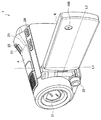
図1および図2は、本発明の実施形態による撮像装置1の外観を示す斜視図である。図1に示したように、撮像装置1は、本体4、ヒンジ機構6、および開閉部8を備える。なお、図1および図2には投影装置の一例として撮像装置1(ビデオカメラ)を示しているが、投影装置はかかる例に限定されない。例えば、投影装置は、PC(Personal Computer)、PDA(Personal Digital Assistants)、家庭用ゲーム機器、携帯電話、PHS(Personal Handyphone System)、携帯用音楽再生装置、携帯用映像処理装置、携帯用ゲーム機器などの情報処理装置であってもよい。
<1. Basic Configuration of Imaging Device according to Embodiment of Present Invention>
1 and 2 are perspective views showing an external appearance of an
撮像装置1の本体4は、ズーム操作部21と、マニュアル操作部22と、静止画撮像操作部23と、モード操作部24と、投影切替操作部25と、撮像光学系31と、を備える。
The
撮像光学系31は、被写体から発せられる光を集光する撮影レンズおよびズームレンズを備え、CCD(Charge Coupled Device)またはCMOS(Complementary Metal Oxide Semiconductor)などの信号変換部に被写体像を形成する撮像部である。被写体像が信号変換部に形成されると、被写体像は信号変換部により電気的な画像信号に変換される。
The imaging
ズーム操作部21は、撮像光学系31の焦点距離を変更するためのユーザ操作を受け付ける。ズーム操作部21は、図1に示したように例えばワイド側またはテレ側に傾倒可能なレバーで構成される。この場合、撮像光学系31は、当該レバーがワイド側に傾倒されると焦点距離を短くし(被写体像を縮小し)、当該レバーがテレ側に傾倒されると焦点距離を長くする(被写体像を拡大する。)。
The
マニュアル操作部22は、撮像光学系31の焦点を合わせるためのユーザ操作を受け付ける。マニュアル操作部22は、図1に示したように例えば時計周り、または反時計周りに回転可能なダイヤルで構成される。この場合、撮像光学系31は、当該ダイヤルの回転方向および回転量に応じて焦点位置を調整する。
The
静止画撮像操作部23は、静止画を撮像するためのユーザ操作を受け付ける。静止画撮像操作部23は、図1に示したように例えば押圧式のボタンで構成される。この場合、撮像装置1は、当該ボタンの押圧に応じて静止画を撮像することにより、静止画の画像データを取得する。
The still image capturing
モード操作部24は、撮像装置1の動作モードを切り替えるためのユーザ操作を受け付ける。ここで、撮像装置1の動作モードは、一例として撮影モードと再生モードとに大別される。また、モード操作部24は、図1に示したように例えば押圧式のボタンで構成される。この場合、撮像装置1は、当該ボタンの押圧に応じて動作モードを撮影モードと再生モードとの間で切り換える。
The
なお、撮影モードは、撮像光学系31および信号変換部などを動作させることにより被写体を撮像するための動作モードである。一方、再生モードは、例えば撮影モードにおいて取得された画像データを再生するための動作モードである。これら動作モードの詳細については図3〜図5を参照して後述する。
The imaging mode is an operation mode for imaging a subject by operating the imaging
投影切替操作部25は、撮像装置1により生成した画面を投影レンズ188から投影するか否かを切り替えるためのユーザ操作を受け付ける。例えば、投影切替操作部25は、図1に示したように例えば押圧式のボタンで構成される。この場合、撮像装置1は、当該ボタンの押圧に応じて画面を投影レンズ188から投影するか否かを切り替える。なお、画面が投影レンズ188から投影されている間、タッチパネル12は、投影画面と同一の画面を表示してもよいし、投影画面と異なる画面を表示してもよいし、画面を非表示にしてもよい。
The projection
以上、撮像装置1の本体4の構成を説明した。続いて、本体4にヒンジ機構6(連結部)を介して連結される開閉部8の構成を説明する。
The configuration of the
開閉部8は、ヒンジ機構6により、図2に示した本体4の上下方向に形成される開閉軸L1回りに開閉可能に、かつ、開閉軸L1と直交する回転軸L2回りに回転可能に本体4と連結されている。図1には、投影レンズ188が外側を向くように開閉部8が本体4に対して閉じられた基本収納状態(閉状態)を示しており、図2には、開閉部8が開閉軸L1回りに回転することにより本体4に対して開かれた状態を示している。
The opening /
このような開閉部8は、図1に示したように、一方の面に投影レンズ188を備え、図2に示したように、他方の面にタッチパネル12を備える。
As shown in FIG. 1, the opening /
タッチパネル12は、表示機能および操作検出機能を有する操作表示部の一例である。タッチパネル12は、撮影モードにおいては撮像光学系31により集光されている被写体の画像を表示し、再生モードにおいては後述のインデックス画面または再生画面などを表示することができる。また、ユーザは、タッチパネル12を操作することにより撮像装置1に各種指示や情報を入力することも可能である。
The
投影レンズ188は、撮像装置1により生成された画面を投影するプロジェクターモジュール(投影部)の一構成要素である。プロジェクターモジュールは、投影切替操作部25に対するユーザ操作に応じ、例えば後述のインデックス画面または再生画面などを投影することができる。このプロジェクターモジュールの構成例については図9を参照して後述する。
The
以上、本発明の実施形態による撮像装置1の外観構成を説明した。続いて、撮像装置1の動作モードである撮影モードおよび再生モードについて説明する。
The external configuration of the
撮影モードは、撮像光学系31および信号変換部などを動作させることにより被写体を撮像するための動作モードである。この撮影モードにおいては、図3に示すように、撮像光学系31による被写体の撮像画面Rがタッチパネル12に表示される。さらに、撮像画面Rが録画中である場合、撮像画面Rには図3に示したように録画マーク62が付加される。
The imaging mode is an operation mode for imaging a subject by operating the imaging
なお、撮影モードにおいてユーザにより静止画撮像操作部24が押圧された場合、撮像装置1は、被写体の静止画を撮像して静止画の画像データを取得する。
When the still image capturing
そして、撮影モードにおいてユーザによりモード操作部24が押圧されると、撮像装置1は動作モードを再生モードに切り替える。再生モードは、コンテンツデータを再生するための動作モードである。このため、撮像装置1は、再生モードへの切替後、再生対象のコンテンツデータをユーザが選択するためのインデックス画面Iを生成する。
Then, when the
図4は、インデックス画面Iの具体例を示した説明図である。図4に示したように、インデックス画面Iは、複数のコンテンツデータの各々に対応するサムネイルs1、s2、s3・・・を含む。なお、コンテンツデータは、撮像装置1が撮像により取得した画像データであってもよいし、外部から取得された画像データであってもよい。また、コンテンツデータのデータ種別は画像データに限定されず、コンテンツデータのデータ種別は、音声データ、ゲーム、またはソフトウェアなどであってもよい。また、各サムネイルsは静止画であってもよいし、動画であってもよい。
FIG. 4 is an explanatory diagram showing a specific example of the index screen I. As shown in FIG. 4, the index screen I includes thumbnails s1, s2, s3,... Corresponding to each of the plurality of content data. Note that the content data may be image data acquired by the
また、インデックス画面Iは、上方スクロールボタン64および下方スクロールボタン66を含み、ユーザは、上方スクロールボタン64または下方スクロールボタン66を選択することにより、インデックス画面Iを任意の方向にスクロールすることができる。
The index screen I includes an
また、ユーザは、インデックス画面Iにおいてカーソル68を所望のサムネイルに合わせることにより、再生対象のコンテンツデータを選択することができる。そして、ユーザによりコンテンツデータの選択が決定されると、撮像装置1は、選択されたコンテンツデータの再生を開始し、当該コンテンツデータの再生画面を生成する。
Further, the user can select content data to be reproduced by moving the
図5は、コンテンツデータの再生画面Pの具体例を示した説明図である。図5に示したように、コンテンツデータの再生画面Pは、停止ボタン71、巻き戻しボタン72、再生/一時停止ボタン73、早送りボタン74、およびリターンボタン76を含む。
FIG. 5 is an explanatory diagram showing a specific example of the content data playback screen P. As shown in FIG. 5, the content data playback screen P includes a
撮像装置1は、ユーザにより停止ボタン71、巻き戻しボタン72、再生/一時停止ボタン73、または早送りボタン74が選択されると、選択されたボタンに応じてコンテンツデータの再生を制御する。例えば、撮像装置1は、ユーザにより停止ボタン71が選択されると、コンテンツデータの再生を停止する。また、撮像装置1は、ユーザによりリターンボタン76が選択されると、コンテンツデータの再生を停止し、インデックス画面Iを生成する。
When the user selects the
なお、上記では撮影モードと再生モードの切替えがモード操作部24へのユーザ操作に応じて行われる例を説明したが、モード切替えのトリガはかかる例に限定されない。例えば、撮像装置1は、撮像画面Rに再生モードへの切替用ボタンを付加し、再生モードへの切替用ボタンがユーザにより選択された場合に動作モードを再生モードに切り替えてもよい。同様に、撮像装置1は、インデックス画面Iや再生画面Pに撮影モードへの切替用ボタンを付加し、撮影モードへの切替用ボタンがユーザにより選択された場合に動作モードを撮影モードに切り替えてもよい。
In addition, although the example in which the switching between the shooting mode and the reproduction mode is performed according to the user operation on the
また、インデックス画面Iの構成は図4に示した例に限定されない。例えば、インデックス画面Iは、画像データに関連する地図上の位置(例えば、撮像位置)に当該画像データのサムネイルが重畳された画面であってもよいし、画像データに関連する時間軸上の位置(例えば、撮像日時)に当該画像データのサムネイルが重畳された画面であってもよい。 Further, the configuration of the index screen I is not limited to the example shown in FIG. For example, the index screen I may be a screen in which a thumbnail of the image data is superimposed on a position on the map (for example, an imaging position) related to the image data, or a position on the time axis related to the image data. It may be a screen in which thumbnails of the image data are superimposed on (for example, imaging date and time).
また、撮像装置1は、再生モードにおいて、上記のインデックス画面Iや再生画面Pをタッチパネル12に表示することも、プロジェクターモジュール18から投影することも可能である。
Further, the
<2.投影レンズの実装位置>
以上、図1〜図5を参照し、本発明の実施形態による撮像装置1の基本構成を説明した。続いて、撮像装置1において投影レンズ188が設けられる位置に関するポイントを説明する。
<2. Mounting position of projection lens>
The basic configuration of the
(第1のポイント)
図6は、開閉部8が本体4に対して直角に開かれた状態を示した説明図である。図6に示したように、投影レンズ188は開閉部8に設けられる。ここで、開閉部8は、開閉軸L1回りに開閉可能に、かつ、開閉軸L1と直交する回転軸L2回りに回転可能に本体4と連結されている。このため、ユーザは、開閉軸L1回り、または回転軸L2回りに開閉部8を回転させることにより、投影レンズ188の向き、すなわち、投影レンズ188からの投影方向を簡易に調節することができる。
(First point)
FIG. 6 is an explanatory view showing a state in which the opening /
(第2のポイント)
また、図6に示したように、投影レンズ188を含むプロジェクターモジュールは、撮像光学系31が設けられる本体4とヒンジ機構6を介して間接的に連結される。このため、投影中にプロジェクターモジュールにおいて発生した熱が撮像光学系31に伝播することを抑制することができる。その結果、プロジェクターモジュールにおいて発生した熱が撮像光学系31に伝播したことにより投影直後に撮影を開始できないという事態を回避可能である。
(Second point)
As shown in FIG. 6, the projector module including the
(第3のポイント)
また、投影レンズ188は、図1に示した基本収納状態において開閉部8の回転軸L2よりも上側に位置するように設けられる。以下、図7および図8を参照し、投影レンズ188を回転軸L2よりも上側に設けることの意義を説明する。
(Third point)
Further, the
図7は、比較例にかかる開閉部96に設けられた投影レンズ98からの投影状態を示した説明図である。図7に示したように、比較例にかかる開閉部96においては、投影レンズ98は開閉部96の回転軸L2よりも下側に設けられる。ここで、ユーザは、撮像装置を床や机に載置して撮像装置に投影を行わせる場合が多いと考えられる。このため、比較例による開閉部96のように、投影レンズ98が開閉部96の回転軸L2よりも下側に設けられる場合、図7に示したように、投影レンズ98から壁への投影画像の下部が机や床に遮られ易いという問題がある。
FIG. 7 is an explanatory diagram showing a projection state from the
これに対し、本実施形態おいては、投影レンズ188を基本収納状態において開閉部8の回転軸L2よりも上側に位置するように設けることにより、図8に示したように、投影レンズ188から壁への投影画像の下部が机や床に遮られてしまう場合を抑制することが可能である。
On the other hand, in this embodiment, by providing the
(第4のポイント)
また、基本収納状態から回転軸L2回りの回転が加えられていない状態において、投影レンズ188から本体4の上側を向く方向に画像が投影されるようにプロジェクターモジュールを構成することにより、上記問題を一層効果的に対処することができる。以下、図9を参照し、このようなプロジェクターモジュールの構成例を説明する。
(4th point)
Further, when the projector module is configured such that an image is projected from the
図9は、プロジェクターモジュールの構成例を示した説明図である。図9に示したように、プロジェクターモジュールは、光源182、光像表示部184、反射板186、および投影レンズ188を含む。
FIG. 9 is an explanatory diagram showing a configuration example of the projector module. As shown in FIG. 9, the projector module includes a
光源182は、白色光を射出する白色LED(Light Emitting Diode)、および白色LEDからの射出光を拡散して光像表示部184に射出する光学系から構成される。なお、本実施形態においては光源182が白色LEDで構成される例に重きをおいて説明するが、光源182の構成はかかる例に限定されない。例えば、光源182は高圧水銀ランプで構成されてもよい。
The
光像表示部184は、投影するための画面を表示する液晶パネルである。光像表示部184に表示された画面は、光源182からの射出光により反射板186に供給される。
The optical
反射板186は、光像表示部184からの入射光を投影レンズ188に向けて反射させる。ここで、反射板186は、基本収納状態から回転軸L2回りの回転が加えられていない状態において、本体4の上側を向く方向に入射光を反射させるような角度を有する。投影レンズ188は、反射板186により反射された画面を投影面に結像させる。
The
このようなプロジェクターモジュールの構成により、投影レンズ188から壁への投影画像の下部が机や床に遮られてしまう場合をより効果的に抑制することが可能である。
With such a projector module configuration, it is possible to more effectively suppress the case where the lower part of the projected image from the
(第5のポイント)
さらに、投影レンズ188は、図6に示したように、開閉部8の回転軸L2の形成方向上でヒンジ機構6から遠い側に設けられる。また、ヒンジ機構6は、撮像光学系31の光軸方向における本体4の被写体側(前方側)に設けられる。かかる構成により、図6に示したように開閉部8が開かれた状態において投影レンズ188から画像を投影する場合に、投影レンズ188からの投影画像が本体4に遮られてしまう場合を抑制することができる。
(5th point)
Further, as shown in FIG. 6, the
<3.本発明の実施形態による撮像装置の機能>
図10は、本発明の実施形態による撮像装置1の構成を示したブロック図である。図10に示したように、本発明の第1の実施形態による撮像装置1は、制御部10、撮影部30および記録再生処理部40を備える。
<3. Function of Imaging Device according to Embodiment of Present Invention>
FIG. 10 is a block diagram illustrating a configuration of the
また、撮影部(撮像部)30は、撮像光学系31、光学系制御部32、信号変換部33、画像信号処理部34、音声入力部35および音声信号処理部36を備える。
The imaging unit (imaging unit) 30 includes an imaging
撮像光学系31は、内部に、被写体を撮像するためのレンズ群、絞り調整機構、フォーカス調整機構、ズーム機構、シャッター機構、フラッシュ機構、および、手ぶれ補正機構などを備え、信号変換部33に被写体像を形成する。
The imaging
光学系制御部32は、制御部10からの制御信号を受けて、撮像光学系31に供給する制御信号を生成する。そして、光学系制御部32は、生成した制御信号を撮影光学系31に供給し、ズーム制御、シャッター制御、および、露出制御などの制御を行う。
The optical
信号変換部33は、上述したように例えばCCDやCMOSなどの撮像素子により構成される。この信号変換部33は、操作入力部20に対するユーザ操作に基づいて制御部10から画像取り込みタイミング信号が供給されると、撮像光学系31により結像面に形成された被写体像を電気的な画像信号に変換し、画像信号処理部34に供給する。なお、撮影モードにおいては制御部10から画像取り込みタイミング信号が連続的に供給されるので、信号変換部33は連続的に被写体像の画像信号の変換を行うことにより、複数フレームの画像信号を取得する。
As described above, the
画像信号処理部34は、制御部10からの制御信号に基づいて、画像信号についてのガンマ補正やAGC(Auto Gain Control)などの処理を行うとともに、画像信号をデジタル形式に変換する処理も行う。
Based on the control signal from the
音声入力部35は、撮影モード時に被写体周辺の音声を収集する。音声入力部35は、収集した音声を電気的な音声信号に変換して音声信号処理部36に供給する。音声信号処理部36は、制御部10からの制御信号に基づいて、音声信号についての補正やAGCなどの処理を行うとともに、音声信号をデジタル形式に変換する処理も行う。
The
また、記録再生処理部40は、図10に示したように、符号化/復号回路41、ディスクインターフェース42、記憶装置44、出力処理部45およびバッファメモリ46を備え、再生部および記録部として機能する。
Further, as shown in FIG. 10, the recording /
符号化/復号部41は、撮影部30から供給される画像信号および音声信号や、時刻情報などの追加記録情報をMPEG方式等により符号化し多重化して、画像データおよび音声データを含む圧縮データに変換する符号化機能を有する。
The encoding /
一方、符号化/復号部41は、圧縮データから画像データおよび音声データなどを分離し、画像データおよび音声データを画像信号および音声信号に復号する復号機能(再生機能)も有する。
On the other hand, the encoding /
また、符号化/復号部41は、制御部10からの制御信号に基づいて、画像信号処理部34から供給される画像信号に対して、自動ホワイトバランス制御、露出補正制御、デジタルズーム倍率に応じた拡大制御などをさらに行う。
In addition, the encoding /
ディスクインターフェース42は、符号化/復号部41から供給された圧縮データを記憶装置44に書き込む。また、ディスクインターフェース42は、記憶装置44から圧縮データを読み出して符号化/復号部41に供給する。なお、記憶装置44は、DVD−R(Digital Versatile Disc Recordable)およびBD(Blu−Ray Disc(登録商標))などの光ディスクであってもよい。
The
出力処理部45は、システムバス109を介して主制御部100により制御される。また、出力処理部45は、符号化/復号部41から供給される圧縮データを制御部10や、編集装置200に供給する。ここで、編集装置200は、例えば、出力処理部45が備える出力端子を介して撮像装置1と接続された情報処理装置であってもよい。ユーザは、この編集装置200を用いて画像データや音声データなどの編集を行うことができる。
The
バッファメモリ46は、例えばSDRAMなどにより構成され、符号化/復号部41における符号化または復号のための作業領域として利用される。
The
また、制御部10は、図10に示したように、主制御部100、ROM(Read Only Memory)101、RAM(Random Access Memory)102、操作入力部20やタッチパネル12からの操作入力を受け付ける操作入力インターフェース103、タッチパネル12を制御する表示制御部104、メモリカード14を装填するメモリカードインターフェース105、撮影時刻の記録などに利用する時間情報を生成する時計回路106、角度センサ16からの信号から開閉部8の角度を検出する角度検出部107、およびプロジェクターモジュール18を制御するプロジェクター制御部108が、システムバス109を介して接続されることにより構成される。
Further, as shown in FIG. 10, the
主制御部100は、撮像装置1全体の処理を司る構成であり、作業領域としてRAM102を使用する。また、主制御部100は、モード操作部24に対するユーザ操作により指定される動作モードに応じた制御を行なう。
The
例えば、動作モードが撮像モードである場合、主制御部100は、プロジェクター制御部108およびプロジェクターモジュール18への電力供給を停止し、表示制御部104を介して、タッチパネル12に画像信号処理部34から供給される画像信号を表示させる。
For example, when the operation mode is the imaging mode, the
また、動作モードが再生モードである場合、主制御部100は、撮影部30への電力供給を停止し、符号化/復号部41から供給される画像データの再生信号またはサムネイルに基づいて再生画面Pまたはインデックス画面Iを生成し、表示制御部104を介してタッチパネル12に再生画面Pまたはインデックス画面Iを表示させる。
When the operation mode is the playback mode, the
ROM101には、撮影部30を制御するためのプログラムや、画像信号や音声信号の記録制御および再生制御などを実行するためのプログラムが書き込まれている。
In the
操作入力インターフェース103は、接続される操作入力部20およびタッチパネル12からの操作信号を主制御部100に伝える。なお、図1に示したズーム操作部21、マニュアル操作部22、静止画撮像操作部23、モード操作部24および投影切替操作部25などを操作入力部20と総称する。
The
表示制御部104は、画像信号処理部34から供給される画像信号や、主制御部100により生成された再生画面Pまたはインデックス画面Iなどをタッチパネル12に表示する制御を行なう。
The
メモリカードインターフェース105は、符号化/復号回路41から供給された圧縮データをメモリカード14に書き込む。また、メモリカードインターフェース105は、メモリカード14から圧縮データを読み出して符号化/復号回路41に供給する。
The
時計回路106は、年、月、日、時間、分、秒などを表わす時間情報を生成する。
The
角度検出部107は、角度センサ16からの信号に基づき、開閉部8の本体4に対する開閉状態および回転状態を検出する。角度センサ16は、例えば、開閉部8の両面に設けられる磁石、および本体4に各磁石の位置に対応して異なる位置に設けられる磁気センサの組からなってもよい。この場合、角度検出部107は、各磁気センサによる磁界の検出結果から、開閉部8が基本収納状態にあるか、反転収納状態にあるか、または開かれた状態にあるかなどを検出することが可能である。さらに、角度検出部107は、開閉部8の本体4に対する開閉角度および回転角度を検出してもよい。
The
プロジェクター制御部108(投影制御部)は、プロジェクターモジュール18から投影面3に画像を投影させるための制御を行なう。プロジェクター制御部108による制御に基づき、例えば再生画面Pまたはインデックス画面Iがプロジェクターモジュール18から投影面3に投影される。
The projector control unit 108 (projection control unit) performs control for projecting an image from the
また、プロジェクター制御部108は、角度検出部107により検出される開閉部8の本体4に対する開閉状態および回転状態に応じ、プロジェクターモジュール18からの投影を中止させる制御を行う。以下、このような制御に基づく撮像装置1の動作を具体的に説明する。
Further, the
<4.本発明の実施形態による撮像装置の動作>
(4−1.第1の動作例)
図11は、開閉部8の反転収納状態を示した説明図である。図11に示したように、反転収納状態は、投影レンズ188が内側を向くように開閉部8が本体4に対して閉じられた状態である。このような反転収納状態において投影が行われると、プロジェクターモジュール18において発生した熱が本体4に伝播し易く、また、投影光が本体4に照射されるので、本体4の撮像光学系31の温度が上昇することが予想される。そこで、第1の動作例として、プロジェクター制御部108は、開閉部8が反転収納状態にある場合にはプロジェクターモジュール18による投影が行われないように制御する。以下、図12を参照して詳細に説明する。
<4. Operation of Imaging Device According to Embodiment of Present Invention>
(4-1. First operation example)
FIG. 11 is an explanatory view showing the inverted storage state of the opening /
図12は、本発明の実施形態による第1の動作例を示したフローチャートである。図12に示したように、プロジェクターモジュール18による投影中に(S204)、開閉部8が反転収納状態であることが角度検出部107により検出された場合(S208)、プロジェクター制御部108は、主制御部100からの命令に従ってプロジェクターモジュール18に投影を中止させる(S212)。
FIG. 12 is a flowchart showing a first operation example according to the embodiment of the present invention. As shown in FIG. 12, during projection by the projector module 18 (S204), when the
そして、S212の後など、プロジェクターモジュール18による投影が行われていない間にユーザにより投影切替操作部25が操作された場合(S216)、プロジェクター制御部108は、開閉部8が反転収納状態でなければ(S220)、プロジェクターモジュール18に投影を開始させる(S224)。
Then, when the projection
一方、プロジェクター制御部108は、開閉部8が反転収納状態であることが角度検出部107により検出された場合(S220)、プロジェクターモジュール18に投影を開始させず、表示制御部104が、タッチパネル12に投影開始のための誘導画面を表示させる(S228)。投影開始のための誘導画面としては、例えば、「タッチパネルを開いて下さい。」や「投影レンズを外側に向けて下さい。」などのメッセージを含む画面が挙げられる。その後、S216からの動作が繰り返される。
On the other hand, when the
以上説明した第1の動作例によれば、反転収納状態で投影が行われる場合を防止できるので、本体4の撮像光学系31の温度上昇を抑制し、投影終了後に円滑に撮影を開始することが可能となる。
According to the first operation example described above, the case where projection is performed in the inverted storage state can be prevented, so that the temperature increase of the imaging
(4−2.第2の動作例)
図1および図2などを参照して説明したように、投影レンズ188は、開閉部8においてタッチパネル12の反対面に設けられる。このため、投影中のユーザによるタッチパネル12の操作性や、ユーザに向かった投影を回避することを考慮すると、開閉部8は、投影レンズ188の向きが開閉軸L1と直交する開閉部8の状態を基準に、例えば図13Aに示したように反時計方向に0〜45度、および図13Bに示したように時計方向に0〜45度などの所定範囲内であることが望まれる。そこで、第2の動作例として、プロジェクター制御部108は、開閉部8の回転角が所定範囲外である場合にはプロジェクターモジュール18による投影が行われないように制御する。以下、図14を参照して詳細に説明する。
(4-2. Second operation example)
As described with reference to FIGS. 1 and 2, the
図14は、本発明の実施形態による第2の動作例を示したフローチャートである。図14に示したように、プロジェクターモジュール18による投影中に(S304)、開閉部8の回転角が所定範囲外であることが角度検出部107により検出された場合(S308)、プロジェクター制御部108は、プロジェクターモジュール18に投影を中止させる(S312)。
FIG. 14 is a flowchart showing a second operation example according to the embodiment of the present invention. As shown in FIG. 14, during projection by the projector module 18 (S304), when the
そして、S312の後など、プロジェクターモジュール18による投影が行われていない間にユーザにより投影切替操作部25が操作された場合(S316)、プロジェクター制御部108は、開閉部8の回転角が所定範囲外でなければ(S320)、プロジェクターモジュール18に投影を開始させる(S324)。
Then, when the projection
一方、プロジェクター制御部108は、開閉部8の回転角が所定範囲外であることが角度検出部107により検出された場合(S320)、プロジェクターモジュール18に投影を開始させず、表示制御部104が、タッチパネル12に投影開始のための誘導画面を表示させる(S328)。投影開始のための誘導画面としては、例えば、「投影レンズを水平方向に向けて下さい。」というメッセージを含む画面が挙げられる。その後、S316からの動作が繰り返される。
On the other hand, when the
以上説明した第2の動作例によれば、開閉部8の回転角が所定範囲外である時に投影が行われる場合を防止できるので、投影中のユーザによるタッチパネル12の操作性を確保することが可能である。
According to the second operation example described above, it is possible to prevent a case where projection is performed when the rotation angle of the opening /
<5.むすび>
以上説明したように、本発明の実施形態によれば、投影レンズ188は開閉部8に設けられるので、ユーザは、開閉軸L1回り、または回転軸L2回りに開閉部8を回転させることにより、投影レンズ188の向き、すなわち、投影レンズ188からの投影方向を簡易に調節することができる。また、投影レンズ188を含むプロジェクターモジュール18は、撮像光学系31が設けられる本体4とヒンジ機構6を介して間接的に連結されるので、プロジェクターモジュールにおいて発生した熱の撮像光学系31への伝播量を抑制することができる。
<5. Conclusion>
As described above, according to the embodiment of the present invention, since the
また、本発明の実施形態によれば、投影レンズ188は基本収納状態において開閉部8の回転軸L2よりも上側に位置するように設けられるので、投影レンズ188から壁への投影画像の下部が机や床に遮られてしまう場合を抑制することが可能である。さらに、本発明の実施形態によれば、開閉部8の本体4に対する開閉状態または回転状態に応じてプロジェクターモジュール18による投影のオンオフを制御することができる。
Further, according to the embodiment of the present invention, the
なお、添付図面を参照しながら本発明の好適な実施形態について詳細に説明したが、本発明はかかる例に限定されない。本発明の属する技術の分野における通常の知識を有する者であれば、特許請求の範囲に記載された技術的思想の範疇内において、各種の変更例または修正例に想到し得ることは明らかであり、これらについても、当然に本発明の技術的範囲に属するものと了解される。 Although the preferred embodiments of the present invention have been described in detail with reference to the accompanying drawings, the present invention is not limited to such examples. It is obvious that a person having ordinary knowledge in the technical field to which the present invention pertains can come up with various changes or modifications within the scope of the technical idea described in the claims. Of course, it is understood that these also belong to the technical scope of the present invention.
例えば、本明細書の撮像装置1の処理における各ステップは、必ずしもフローチャートとして記載された順序に沿って時系列に処理する必要はない。例えば、撮像装置1の処理における各ステップは、フローチャートとして記載した順序と異なる順序で処理されても、並列的に処理されてもよい。
For example, each step in the processing of the
また、撮像装置1に内蔵されるハードウェアを、上述した撮像装置1の各構成と同等の機能を発揮させるためのコンピュータプログラムも作成可能である。また、該コンピュータプログラムを記憶させた記憶媒体も提供される。
Further, it is possible to create a computer program for causing the hardware built in the
1 撮像装置
4 本体
6 ヒンジ機構
8 開閉部
12 タッチパネル
10 制御部
16 角度センサ
18 プロジェクターモジュール
20 操作入力部
21 ズーム操作部
22 マニュアル操作部
23 静止画撮像操作部
24 モード操作部
25 投影切替操作部
30 撮影部
31 撮像光学系
40 記録再生処理部
100 主制御部
107 角度検出部
108 プロジェクター制御部
188 投影レンズ
DESCRIPTION OF
Claims (6)
投影レンズを含む投影部と、
前記投影レンズが設けられ、前記装置本体の上下方向に形成される開閉軸を中心に開閉可能に、かつ、前記開閉軸に直交する回転軸を中心に回転可能に連結された開閉部と;
を備え、
前記投影レンズは、前記投影レンズが外側を向くように前記開閉部が前記装置本体に対して閉じられた閉状態において、前記開閉部の回転軸より上側に位置するように設けられ、
前記投影部は、前記開閉部が前記閉状態から回転無しに開かれた状態において前記装置本体の上側を向く方向に画像を投影する、投影装置。 The device body;
A projection unit including a projection lens;
An opening / closing section provided with the projection lens, openable / closable around an opening / closing axis formed in the vertical direction of the apparatus body, and rotatably connected around a rotation axis orthogonal to the opening / closing axis;
With
The projection lens is provided so as to be positioned above the rotation axis of the opening / closing portion in a closed state in which the opening / closing portion is closed with respect to the apparatus main body so that the projection lens faces outward.
The projection unit projects an image in a direction facing the upper side of the apparatus main body when the opening / closing unit is opened without rotation from the closed state .
撮像部と;
前記開閉部と前記装置本体とを連結する連結部と;
を有し、
前記連結部は、前記撮像部の光軸方向における被写体側に位置する、請求項1に記載の投影装置。 The apparatus main body is
An imaging unit;
A connecting part for connecting the opening / closing part and the apparatus main body;
Have
The projection device according to claim 1, wherein the connection unit is located on a subject side in the optical axis direction of the imaging unit.
前記開閉部の前記装置本体に対する連結状態を検出する検出部と;
前記検出部による検出結果に応じて前記投影部に画像を投影させるか否かを制御する投影制御部と;
をさらに備える、請求項1に記載の投影装置。 The projector is
A detection unit for detecting a connection state of the opening / closing unit with respect to the apparatus main body;
A projection control unit for controlling whether or not to project an image on the projection unit according to a detection result by the detection unit;
The projection apparatus according to claim 1 , further comprising:
The projection control unit, when the rotation angle of the opening and closing portion is detected the connected state is out of the predetermined range by the detection unit, an image from the projection unit controls the projection unit so as not to be projected, claim 4 The projection apparatus described in 1.
Priority Applications (5)
| Application Number | Priority Date | Filing Date | Title |
|---|---|---|---|
| JP2010251674A JP5609561B2 (en) | 2010-11-10 | 2010-11-10 | Projection device |
| US13/235,826 US9033519B2 (en) | 2010-11-10 | 2011-09-19 | Projection device having an open/close unit provided with a projection lens |
| KR1020110113397A KR20120089552A (en) | 2010-11-10 | 2011-11-02 | Projection device |
| EP11187498A EP2453643A1 (en) | 2010-11-10 | 2011-11-02 | Projection device |
| CN2011103407590A CN102540663A (en) | 2010-11-10 | 2011-11-02 | Projection device |
Applications Claiming Priority (1)
| Application Number | Priority Date | Filing Date | Title |
|---|---|---|---|
| JP2010251674A JP5609561B2 (en) | 2010-11-10 | 2010-11-10 | Projection device |
Publications (3)
| Publication Number | Publication Date |
|---|---|
| JP2012103465A JP2012103465A (en) | 2012-05-31 |
| JP2012103465A5 JP2012103465A5 (en) | 2013-11-21 |
| JP5609561B2 true JP5609561B2 (en) | 2014-10-22 |
Family
ID=44907763
Family Applications (1)
| Application Number | Title | Priority Date | Filing Date |
|---|---|---|---|
| JP2010251674A Expired - Fee Related JP5609561B2 (en) | 2010-11-10 | 2010-11-10 | Projection device |
Country Status (5)
| Country | Link |
|---|---|
| US (1) | US9033519B2 (en) |
| EP (1) | EP2453643A1 (en) |
| JP (1) | JP5609561B2 (en) |
| KR (1) | KR20120089552A (en) |
| CN (1) | CN102540663A (en) |
Families Citing this family (7)
| Publication number | Priority date | Publication date | Assignee | Title |
|---|---|---|---|---|
| JP2013231747A (en) * | 2012-04-27 | 2013-11-14 | Sony Corp | Imaging device and projector unit |
| US9992453B2 (en) | 2012-07-20 | 2018-06-05 | Freedom Scientific, Inc. | Multiposition magnifier camera |
| CN103885270A (en) * | 2012-12-19 | 2014-06-25 | 鑫晶鑚科技股份有限公司 | Image taking device provided with protective lens, and projection device |
| US10819962B2 (en) | 2012-12-28 | 2020-10-27 | Apple Inc. | Method of and system for projecting digital information on a real object in a real environment |
| US9560279B2 (en) * | 2013-03-11 | 2017-01-31 | Tera Xtal Technology Corporation | Camera device and projector device having protective lens |
| CN103634525B (en) * | 2013-11-26 | 2017-06-16 | 广东欧珀移动通信有限公司 | Rotation of mobile terminal camera display system changing method |
| EP3420397A4 (en) | 2016-02-26 | 2019-12-04 | Freedom Scientific, Inc. | Magnifier device with adjustable camera |
Family Cites Families (17)
| Publication number | Priority date | Publication date | Assignee | Title |
|---|---|---|---|---|
| US6930669B2 (en) | 2002-03-18 | 2005-08-16 | Technology Innovations, Llc | Portable personal computing device with fully integrated projection display system |
| CN1262101C (en) * | 2003-03-26 | 2006-06-28 | 英华达股份有限公司 | Structure capable of switching cell phone into digital camera |
| JP4533641B2 (en) * | 2004-02-20 | 2010-09-01 | オリンパス株式会社 | Portable projector |
| US7500758B1 (en) * | 2004-03-04 | 2009-03-10 | Sanyo Electric Co., Ltd. | Cameras and video players having image projection capabilities |
| JP4371016B2 (en) * | 2004-09-09 | 2009-11-25 | 株式会社ニコン | Electronics |
| JP4556573B2 (en) * | 2004-09-09 | 2010-10-06 | 株式会社ニコン | Electronic device provided with projector device |
| JP2006091112A (en) * | 2004-09-21 | 2006-04-06 | Nikon Corp | Electronic equipment |
| EP1903387B1 (en) | 2005-07-01 | 2011-01-26 | Nikon Corporation | Projection device |
| JP4437777B2 (en) * | 2005-09-27 | 2010-03-24 | シャープ株式会社 | Mobile terminal with projector function |
| JP2007219225A (en) | 2006-02-17 | 2007-08-30 | Seiko Epson Corp | Projector |
| JP4924471B2 (en) * | 2008-02-26 | 2012-04-25 | 日本電気株式会社 | Mobile communication terminal, projection method and program |
| JP2009244322A (en) * | 2008-03-28 | 2009-10-22 | Sanyo Electric Co Ltd | Projector device |
| JP2009244977A (en) | 2008-03-28 | 2009-10-22 | Toshiba Corp | Information processing apparatus |
| JP2010114476A (en) * | 2008-11-04 | 2010-05-20 | Panasonic Corp | Video camera apparatus |
| JP2010177879A (en) * | 2009-01-28 | 2010-08-12 | Kyocera Corp | Cell phone |
| JP5383318B2 (en) * | 2009-03-26 | 2014-01-08 | 京セラ株式会社 | Portable electronic devices |
| JP2010251674A (en) | 2009-04-10 | 2010-11-04 | Nochi Seiko Co Ltd | Manufacturing method of subjecting thin foil to press-bonding with silicon |
-
2010
- 2010-11-10 JP JP2010251674A patent/JP5609561B2/en not_active Expired - Fee Related
-
2011
- 2011-09-19 US US13/235,826 patent/US9033519B2/en not_active Expired - Fee Related
- 2011-11-02 EP EP11187498A patent/EP2453643A1/en not_active Withdrawn
- 2011-11-02 KR KR1020110113397A patent/KR20120089552A/en not_active Application Discontinuation
- 2011-11-02 CN CN2011103407590A patent/CN102540663A/en active Pending
Also Published As
| Publication number | Publication date |
|---|---|
| JP2012103465A (en) | 2012-05-31 |
| KR20120089552A (en) | 2012-08-13 |
| EP2453643A1 (en) | 2012-05-16 |
| CN102540663A (en) | 2012-07-04 |
| US9033519B2 (en) | 2015-05-19 |
| US20120113401A1 (en) | 2012-05-10 |
Similar Documents
| Publication | Publication Date | Title |
|---|---|---|
| JP5609561B2 (en) | Projection device | |
| JP2005301992A (en) | Electronic apparatus with display unit, information-processing method and program for making computer execute the same program | |
| JP2011188065A (en) | Imaging controller, method of detecting subject, and program | |
| US8897625B2 (en) | Slideshow display control for a display control apparatus | |
| JP2006080779A (en) | Information processor, information processing method, and program | |
| JP5707814B2 (en) | Projection apparatus, projection control method, and program | |
| JP5072042B2 (en) | Imaging device with projection display function and portable imaging projector | |
| JP2013090056A (en) | Image reproduction device and camera | |
| JP2012039361A (en) | Imaging device and imaging method | |
| JP5621511B2 (en) | Projection apparatus, projection method, and program | |
| JP2008086023A (en) | Electronic device with imaging function, and method for controlling electronic device with imaging function, and program | |
| JP2012070292A (en) | Imaging apparatus, control method therefor, and program | |
| JP6094613B2 (en) | Projection control device, display control device, and display control method | |
| JP2008234687A (en) | Electronic device with imaging function, method for controlling electronic device with imaging function, and program | |
| US8576344B2 (en) | Projection control device, projection control method, and program | |
| JP4899994B2 (en) | Digital camera | |
| KR101946574B1 (en) | Apparatus and method for reproducing image and computer-readable storage medium | |
| JP2008252675A (en) | Digital camera | |
| JP2005252797A (en) | Digital camera | |
| JP2008252673A (en) | Digital camera | |
| JP2009177836A (en) | Information processor, information processing method, and program | |
| JP2012142656A (en) | Image display device | |
| JP2006047416A (en) | Imaging device, imaging operation informing method and program |
Legal Events
| Date | Code | Title | Description |
|---|---|---|---|
| A521 | Request for written amendment filed |
Free format text: JAPANESE INTERMEDIATE CODE: A523 Effective date: 20131008 |
|
| A621 | Written request for application examination |
Free format text: JAPANESE INTERMEDIATE CODE: A621 Effective date: 20131008 |
|
| A977 | Report on retrieval |
Free format text: JAPANESE INTERMEDIATE CODE: A971007 Effective date: 20140324 |
|
| A131 | Notification of reasons for refusal |
Free format text: JAPANESE INTERMEDIATE CODE: A131 Effective date: 20140408 |
|
| A521 | Request for written amendment filed |
Free format text: JAPANESE INTERMEDIATE CODE: A523 Effective date: 20140521 |
|
| TRDD | Decision of grant or rejection written | ||
| A01 | Written decision to grant a patent or to grant a registration (utility model) |
Free format text: JAPANESE INTERMEDIATE CODE: A01 Effective date: 20140805 |
|
| A61 | First payment of annual fees (during grant procedure) |
Free format text: JAPANESE INTERMEDIATE CODE: A61 Effective date: 20140818 |
|
| LAPS | Cancellation because of no payment of annual fees |