CN102540663A - Projection device - Google Patents
Projection device Download PDFInfo
- Publication number
- CN102540663A CN102540663A CN2011103407590A CN201110340759A CN102540663A CN 102540663 A CN102540663 A CN 102540663A CN 2011103407590 A CN2011103407590 A CN 2011103407590A CN 201110340759 A CN201110340759 A CN 201110340759A CN 102540663 A CN102540663 A CN 102540663A
- Authority
- CN
- China
- Prior art keywords
- unit
- main body
- projection
- apparatus main
- image
- Prior art date
- Legal status (The legal status is an assumption and is not a legal conclusion. Google has not performed a legal analysis and makes no representation as to the accuracy of the status listed.)
- Pending
Links
Images


Classifications
-
- H—ELECTRICITY
- H04—ELECTRIC COMMUNICATION TECHNIQUE
- H04N—PICTORIAL COMMUNICATION, e.g. TELEVISION
- H04N9/00—Details of colour television systems
- H04N9/12—Picture reproducers
- H04N9/31—Projection devices for colour picture display, e.g. using electronic spatial light modulators [ESLM]
- H04N9/3141—Constructional details thereof
- H04N9/3173—Constructional details thereof wherein the projection device is specially adapted for enhanced portability
- H04N9/3176—Constructional details thereof wherein the projection device is specially adapted for enhanced portability wherein the projection device is incorporated in a camera
-
- H—ELECTRICITY
- H04—ELECTRIC COMMUNICATION TECHNIQUE
- H04N—PICTORIAL COMMUNICATION, e.g. TELEVISION
- H04N5/00—Details of television systems
- H04N5/74—Projection arrangements for image reproduction, e.g. using eidophor
-
- G—PHYSICS
- G03—PHOTOGRAPHY; CINEMATOGRAPHY; ANALOGOUS TECHNIQUES USING WAVES OTHER THAN OPTICAL WAVES; ELECTROGRAPHY; HOLOGRAPHY
- G03B—APPARATUS OR ARRANGEMENTS FOR TAKING PHOTOGRAPHS OR FOR PROJECTING OR VIEWING THEM; APPARATUS OR ARRANGEMENTS EMPLOYING ANALOGOUS TECHNIQUES USING WAVES OTHER THAN OPTICAL WAVES; ACCESSORIES THEREFOR
- G03B21/00—Projectors or projection-type viewers; Accessories therefor
-
- H—ELECTRICITY
- H04—ELECTRIC COMMUNICATION TECHNIQUE
- H04N—PICTORIAL COMMUNICATION, e.g. TELEVISION
- H04N23/00—Cameras or camera modules comprising electronic image sensors; Control thereof
- H04N23/50—Constructional details
- H04N23/53—Constructional details of electronic viewfinders, e.g. rotatable or detachable
- H04N23/531—Constructional details of electronic viewfinders, e.g. rotatable or detachable being rotatable or detachable
-
- H—ELECTRICITY
- H04—ELECTRIC COMMUNICATION TECHNIQUE
- H04N—PICTORIAL COMMUNICATION, e.g. TELEVISION
- H04N23/00—Cameras or camera modules comprising electronic image sensors; Control thereof
- H04N23/60—Control of cameras or camera modules
- H04N23/63—Control of cameras or camera modules by using electronic viewfinders
- H04N23/631—Graphical user interfaces [GUI] specially adapted for controlling image capture or setting capture parameters
- H04N23/632—Graphical user interfaces [GUI] specially adapted for controlling image capture or setting capture parameters for displaying or modifying preview images prior to image capturing, e.g. variety of image resolutions or capturing parameters
Abstract
There is provided a projection device including a device main body, and an open/close unit having a projection lens, the open/close unit being connected to the device main body in a manner openable and closable about an open/close axis formed in a vertical direction of the device main body and in a manner rotatable about a rotation axis that is perpendicular to the open/close axis. The projection lens is, in a closed state in which the open/close unit is closed with respect to the device main body such that the projection lens faces outward, provided on an upper side of the rotation axis of the open/close unit.
Description
Technical field
The disclosure relates to a kind of projection arrangement.
Background technology
In the prior art, imaging device has been mounted liquid crystal panel, through watching the demonstration of liquid crystal panel, the content such as moving image or rest image that the user can use the liquid crystal panel inspection to be caught by imaging device.In addition, if imaging device is connected to projection arrangement, so the user can be on giant-screen the scope of examination.Note that and for example describing a kind of projection arrangement among the JP 2007-219225A.
Also proposed projector module is installed on the imaging device.According to such imaging device, moving image etc. can be immediately by projection after imaging processing, and does not need this imaging device to be connected to projection arrangement.
Summary of the invention
But, because the imaging device of prior art has near the projector module that image-generating unit, provides, therefore will be transmitted to image-generating unit in the heat that in projector module, produces during the projection, this will make that after projection, beginning imaging immediately becomes very difficult.In addition, use the imaging device of prior art, because the relation between imaging direction and the projecting direction fixes, so under the situation of mobile imaging device main body not, will be difficult to adjust projecting direction.In addition, it will also be appreciated that when the imaging device was placed on desk or the floor, according to the installation site of projector module, the bottom that projects to the image on the wall can be displayed on desk or the floor.
In view of the foregoing, be desirable to provide a kind of new, improved projection arrangement that can improve user's availability.
According to embodiment of the present disclosure; Provide a kind of and comprise apparatus main body and have the projection arrangement of the ON/OFF unit of projecting lens, the mode that this ON/OFF unit opens and closes with the ON/OFF axle that forms on the vertical direction that can be centered around apparatus main body and being connected to apparatus main body around mode perpendicular to the turning axle rotation of ON/OFF axle.Make projecting lens in the closed condition of outside thereby close with respect to apparatus main body in the ON/OFF unit, projecting lens is positioned at the upside of the turning axle of ON/OFF unit.
Apparatus main body can comprise image-generating unit and the coupling part that connects ON/OFF unit and apparatus main body.The quilt that the coupling part can be positioned on the optical axis direction of image-generating unit is taken the photograph body one side.
Projecting lens may be provided in the side away from the coupling part on the direction that the turning axle of ON/OFF unit is formed.
Projection arrangement can also comprise the projecting cell that comprises projecting lens, and this projecting cell can be configured to: under the situation that has rotation, do not open the state of ON/OFF unit from closed condition, at projected image on the direction of the upside of apparatus main body.
Projection arrangement can also comprise: be configured to detect the detecting unit of ON/OFF unit with respect to the connection status of apparatus main body; And be configured to control whether make the projection control module of projecting cell projected image according to the testing result that obtains by detecting unit.
Thereby close when making projecting lens towards the connection status of inside with respect to apparatus main body when detecting unit has detected the ON/OFF unit, the projection control module can be controlled projecting cell, thereby makes not projected image of projecting cell.
During the connection status of the rotation angle that has detected the ON/OFF unit when detecting unit outside preset range, the projection control module can be controlled projecting cell, makes not projected image of projecting cell.
As stated, according to the disclosure, can improve the availability of user for projection arrangement.
Description of drawings
Fig. 1 is the skeleton view that illustrates according to the outward appearance of the imaging device of disclosure embodiment;
Fig. 2 is the skeleton view that illustrates according to the outward appearance of the imaging device of disclosure embodiment;
Fig. 3 is the key drawing that the object lesson of imaging screen is shown;
Fig. 4 is the key drawing that the object lesson of index screen (index screen) is shown;
Fig. 5 is the key drawing that the object lesson of playback screen (playback screen) is shown;
Fig. 6 illustrates the key drawing with the state opened with respect to the right angle of main body of ON/OFF unit wherein;
Fig. 7 is the key drawing that illustrates from the state of the projection of the projecting lens that provides on the ON/OFF unit according to comparative example;
Fig. 8 is the key drawing that illustrates from the state of the projection of the projecting lens 188 that provides on the ON/OFF unit 8 according to disclosure embodiment;
Fig. 9 is the key drawing that the configuration example of projector module is shown;
Figure 10 is the block diagram that illustrates according to the configuration of the imaging device of disclosure embodiment;
Figure 11 is the key drawing of upset store status (flipped storage state) that the ON/OFF unit is shown;
Figure 12 is the process flow diagram that illustrates according to first example of operation of disclosure embodiment;
Figure 13 A is the key drawing of example ranges that the rotation angle of the ON/OFF unit that can be used for carrying out projection is shown;
Figure 13 B is the key drawing of example ranges that the rotation angle of the ON/OFF unit that can be used for carrying out projection is shown; And
Figure 14 is the process flow diagram that illustrates according to second example of operation of disclosure embodiment.
Embodiment
Hereinafter, with the preferred embodiment that invention will be described in detail with reference to the attached drawing.Note that in this instructions and accompanying drawing the element that has identical functions and structure is basically represented with identical Reference numeral, and omitted the repetition of explanation to these structural details.
In this instructions and accompanying drawing, have substantially the same function and can follow different letters at the back at it, thereby can easily distinguish them with structure and by the represented a plurality of structural details of identical Reference numeral.But, when need not be in having a plurality of structural details of substantially the same function and structure each between when carrying out special differentiation, will only distribute Reference numeral.
To " embodiment " be described according to following order.
1. according to the basic configuration of the imaging device of disclosure embodiment
2. the installation site of projecting lens
3. according to the function of the imaging device of disclosure embodiment
4. according to the operation of the imaging device of disclosure embodiment
4-1. first example of operation
4-2. second example of operation
5. sum up
The basic configuration of the imaging device of disclosure embodiment < 1. according to >
Fig. 1 and Fig. 2 are for all illustrating the skeleton view according to the outward appearance of the imaging device 1 of disclosure embodiment.As shown in Figure 1, imaging device 1 comprises main body 4, linkage 6 and ON/OFF unit 8.Though Fig. 1 and Fig. 2 all illustrate the example of imaging device 1 (video camera) as projection arrangement, projection arrangement is not limited thereto.For example, projection arrangement can be the signal conditioning package such as PC (personal computer), PDA (personal digital assistant), family game machine, portable phone, PHS (personal handyphone system), portable music playback reproducer, portable image treating apparatus or portable game machine.
The main body 4 of imaging device 1 comprises: zoom operation unit 21, manual operation unit 22, still image capturing operating unit 23, pattern operating unit 24, projection blocked operation unit 25 and image formation optical unit 31.
Image formation optical unit 31 is such image-generating units; This image-generating unit comprises and is used to assemble capture lens (shooting lens) and the zoom lens from the light of being taken the photograph the body emission, and this image-generating unit forms the image of being taken the photograph body at the signal conversion unit place such as CCD (charge-coupled image sensor) or CMOS (complementary metal oxide semiconductor (CMOS)).When the image of body was taken the photograph in formation at the signal conversion unit place, the image of being taken the photograph body converted electrical picture signal to by signal conversion unit.
Still image capturing operating unit 23 receives the user's operation that is used for capturing still image.For example, still image capturing operating unit 23 comprises button as shown in Figure 1.In this case, imaging device 1 basis is applied to the pressure capturing still image of this button, thereby obtains the view data of rest image.
Note that screening-mode is the operator scheme that is used for catching through operation image formation optical unit 31, signal conversion unit etc. the image of being taken the photograph body.Simultaneously, playback mode is the operator scheme that is used for the view data that playback for example obtains at screening-mode.The details of these operator schemes is described to Fig. 5 with reference to Fig. 3 below.
Projection blocked operation unit 25 receives the user's operation that whether is used to switch the screen that has been produced by imaging device 1 from projecting lens 188 projections.For example, projection blocked operation unit 25 comprises button for example as shown in Figure 1.In this case, whether imaging device 1 switches from projecting lens 188 projection screens according to the pressure that is applied to this button.Note that touch panel 12 can show the screen identical with projection screen in projecting lens 188 projection screens, show the screen different, perhaps display screen not with projection screen.
Above-described is the configuration of the main body 4 of imaging device 1.Below, the configuration that is connected to the ON/OFF unit 8 of main body 4 via linkage 6 (coupling part) will be described.
As shown in Figure 2; ON/OFF unit 8 is connected to main body 4 via linkage 6; Thereby make ON/OFF unit 8 to be centered around to form on the vertical direction of main body 4 ON/OFF axle L1 open and close, and can be around turning axle L2 rotation perpendicular to ON/OFF axle L1.Fig. 1 illustrates basic store status (closed condition): wherein, thereby ON/OFF unit 8 is closed with respect to main body 4 and is made projecting lens 188 towards the outside; And Fig. 2 illustrates such state: wherein, ON/OFF unit 8 rotates around ON/OFF axle L1, thereby makes ON/OFF unit 8 open with respect to main body 4.
Such ON/OFF unit 8 is as shown in Figure 1 to have projecting lens 188 on one surface, and as shown in Figure 2ly on its another surface, has touch panel 12.
Projecting lens 188 is projection element by the projector module (projecting cell) of the screen of imaging device 1 generation.In response to the operation of user to projection blocked operation unit 25, projector module can projection for example the index screen described of hereinafter, playback screen etc.With reference to Fig. 9 the configuration example of projector module is described below.
Above-described is outward appearance/configuration according to the imaging device 1 of disclosure embodiment.Below, with screening-mode and the playback mode described as the operator scheme of imaging device 1.
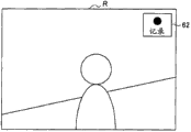
Screening-mode is the operator scheme that is used for catching through operation image formation optical unit 31, signal conversion unit etc. the image of being taken the photograph body.In this screening-mode, as shown in Figure 3, the imaging screen R that is taken the photograph body by the quilt of image formation optical unit 31 acquisitions is presented on the touch panel 12.In addition, as shown in Figure 3 when being recorded as picture screen R, record mark 62 is added to imaging screen R.
Note that when user in screening-mode pushes still image capturing operating unit 23, imaging device 1 catch taken the photograph body rest image to obtain the view data of this rest image.
Then, when user in screening-mode pressed die pressing type operating unit 24, imaging device 1 switched to playback mode with operator scheme.Playback mode is the operator scheme that is used for playing back content data.Therefore, after operator scheme was switched to playback mode, imaging device 1 produced index screen I, so that the user selects to want the content-data of playback.
Fig. 4 is the key drawing that the object lesson of index screen I is shown.As shown in Figure 4, index screen I comprises thumbnail s1, s2, s3......, and each thumbnail is all corresponding to a plurality of content-datas.Note that content-data can be the view data of perhaps being obtained from the outside by the view data that imaging device 1 obtains through imaging.In addition, the data type of content-data is not limited to view data, and the data type of content-data can be voice data, recreation, software etc.In addition, each thumbnail can be rest image or moving image.
Index screen I comprises scroll up button 64 and downward scroll button 66.The user can roll through selecting scroll up button 64 or downward scroll button 66 to go up on index screen I in any direction.
In addition, the user can be through selecting to want the content-data of playback on the thumbnail that cursor 68 is placed into the expectation on the index screen I.Then, when the content-data confirming by the user to select, content-data that imaging device 1 beginning playback is selected and the playback screen that produces this content-data.
Fig. 5 is the key drawing of object lesson that the playback screen P of content-data is shown.As shown in Figure 5, the playback screen P of content-data comprises: stop button 71, fast backward button (fast-rewindbutton) 72, broadcast/pause button 73, fast forward button (fast-forward button) 74 and return push-button 76.
When the user selected stop button 71, fast backward button 72, broadcast/pause button 73 or fast forward button 74, imaging device 1 was according to the playback of the button control content-data of selecting.For example, when the user selected stop button 71, imaging device 1 stopped the playback of content-data.In addition, when the user selected return push-button 76, imaging device 1 stopped the playback of content-data, and produced index screen I.
Although be described carrying out the example that switches operating between screening-mode and the playback mode on the pattern operating unit 24 hereinbefore, the triggering of switch mode is not limited to this according to the user.For example, be used for the button that operator scheme switches to playback mode can be added to imaging screen R, thereby make that imaging device 1 can switch to playback mode with operator scheme when being used for the button that operator scheme switches to playback mode selected by the user.Likewise; The button that is used for operator scheme is switched to screening-mode can be added to index screen I or playback screen P; Thereby make that imaging device 1 can switch to screening-mode with operator scheme when being used for the button that operator scheme switches to screening-mode selected by the user.
The configuration of index screen I is not limited to the example shown in Fig. 4.For example; Index screen I can be such screen: wherein, the thumbnail of view data is coated on the position relevant with view data (for example, image space) on the map; Perhaps; Index screen I can be such screen: wherein, the thumbnail of view data is coated on the position relevant with view data (for example, imaging date and time) on the time shaft.
In addition, the imaging device in playback mode can show aforesaid index screen I or playback screen P on touch panel 12, and can be from this screen of projector module 18 projections.
< the 2. installation site of projecting lens >
What describe to Fig. 5 above with reference to Fig. 1 is the basic configuration according to the imaging device 1 of disclosure embodiment.Below, with describing the main points relevant with the position of the projecting lens that in imaging device 1, provides 188.
(first point)
Fig. 6 illustrates the key drawing with the state opened with respect to the right angle of main body 4 of ON/OFF unit 8 wherein.As shown in Figure 6, projecting lens 188 provides on ON/OFF unit 8.Here, ON/OFF unit 8 is connected to main body 4, thereby makes ON/OFF unit 8 to open and close around ON/OFF axle L1, and can be around the turning axle L2 rotation perpendicular to ON/OFF axle L1.Therefore, through around ON/OFF axle L1 or around turning axle L2 rotation ON/OFF unit 8, the user can easily adjust projecting lens 188 towards direction, that is, and from the projecting direction of projecting lens 188.
(second point)
As shown in Figure 6, comprise that the projector module of projecting lens 188 is connected with the main body with image formation optical unit 31 4 via linkage 6 indirectly.Therefore, during projection, can be suppressed at the propagation of the heat that produces in the projector module towards image formation optical unit 31.As a result, can avoid propagating towards image formation optical unit 31 and causing to begin immediately after the projection situation about forming images owing to the heat that in projector module, produces.
(thirdly)
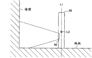
Projecting lens 188 provides like this: in basic store status shown in Figure 1, it is positioned at the upside of turning axle L2.The importance of projecting lens 188 will be provided with reference to the upside that Fig. 7 and Fig. 8 are described in turning axle L2 hereinafter.
Fig. 7 is the key drawing that illustrates from the state of the projection of the projecting lens 98 that provides on the ON/OFF unit 96 according to comparative example.As shown in Figure 7, on the ON/OFF unit 96 according to comparative example, projecting lens 98 provides at the downside of the turning axle L2 of ON/OFF unit 96.Here, consider under many circumstances that when imaging device being placed on floor or the desk, the user can make imaging device carry out projection.Therefore; When the downside of projecting lens 98 turning axle L2 of (as according to the ON/OFF unit 96 of comparative example) in ON/OFF unit 96 provides; Such problem can occur: the bottom that projects to the image on the wall from projecting lens 98 can be easy to blocked by desk or floor, and is as shown in Figure 7.
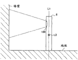
Different therewith is; In the present embodiment; Projecting lens provides like this: in basic store status; It is positioned at the upside of the turning axle L2 of ON/OFF unit 8, thereby can suppress to project to the possibility that the bottom of the image on the wall can be blocked by desk or wall from projecting lens 188, and is as shown in Figure 8.
(the 4th point)
If projector module is constructed like this: make not to be added in the state of basic store status in rotation around turning axle L2; On the direction of the upside of main body 4 from projecting lens 188 projected images, foregoing problems even can more effectively be able to solve so.Hereinafter, will describe the configuration example of such projector module with reference to Fig. 9.
Fig. 9 is the key drawing that the configuration example of projector module is shown.As shown in Figure 9, projector module comprises light source 182, optical imagery display unit 184, reflecting plate 186 and projecting lens 188.
Optical imagery display unit 184 is the liquid crystal panels that show the screen that is used for projection.The screen that on optical imagery display unit 184, shows is supplied to reflecting plate 186 through the light from light source 182 emissions.
Reflecting plate 186 will reflect to projecting lens 188 from the incident light of optical imagery display unit 184.Here, be not added in the state of basic store status around the rotation of turning axle L2, reflecting plate 186 has incident light in the angle that on the direction of the upside of main body 4, reflects.Projecting lens 188 forms the image by the screen of reflecting plate 186 reflections on projection plane.
According to the configuration of aforesaid projector module, can more effectively suppress to project to the possibility that the bottom of the image on the wall can be blocked by desk or floor from projecting lens 188.
(the 5th point)
In addition, as shown in Figure 6, projecting lens 188 is provided at the side away from linkage 6 on the direction that the turning axle L2 of ON/OFF unit 8 is formed.In addition, linkage 6 quilt that is provided at the main body 4 on the optical axis direction of image formation optical unit 31 is taken the photograph body one side (front side).According to such configuration,, can suppress the possibility that to be blocked by main body 4 from the image of projecting lens 188 projections when in the state of opening in ON/OFF unit 8 as shown in Figure 6 during from projecting lens 188 projected images.
The function of the imaging device of disclosure embodiment < 3. according to >
Figure 10 is the block diagram that illustrates according to the configuration of the imaging device 1 of disclosure embodiment.Shown in figure 10, comprise control module 10, take unit 30 and recording/playback processing unit 40 according to the imaging device 1 of the disclosure first embodiment.
In addition, take unit (image-generating unit) 30 and comprise image formation optical unit 31, optical unit control module 32, signal conversion unit 33, image signal processing unit 34, audio frequency input block 35 and audio signal processing unit 36.
Image formation optical unit 31 comprises and is used for the lens combination of being taken the photograph volume imaging, diaphragm adjusting mechanism, focuses on adjusting mechanism, zoom mechanism, tripper, flash unit, shake correction mechanism etc., and forms the image of being taken the photograph body at signal conversion unit 33 places.
In case receive the control signal from control module 10, optical unit control module 32 produces the control signal that will be supplied to image formation optical unit 31.Then, optical unit control module 32 is supplied to image formation optical unit 31 with the control signal that produces and carries out the control such as zoom control, fast gate control and exposure control.
As stated, for example, signal conversion unit 33 comprises the imageing sensor such as CCD or CMOS.When based on the user in the operation of operation on the input block 20 from control module 10 during to signal conversion unit 33 supply Image Acquisition timing signals; The image transitions that the quilt that signal conversion unit 33 will have been formed on imaging plane by image formation optical unit 31 is taken the photograph body is an electrical picture signal, and this electrical picture signal is supplied to image signal processing unit 34.In screening-mode, the Image Acquisition timing signal is continuously from control module 10 supplies.Like this, signal conversion unit 33 obtains the picture signal of multiframe through changing the picture signal of being taken the photograph body continuously.
Based on the control signal from control module 10,34 pairs of picture signals of image signal processing unit are carried out the processing such as Gamma correction and AGC (automatic gain control), and carry out the processing that picture signal is converted into digital format.
Audio frequency input block 35 is collected in screening-mode and is taken the photograph body sound on every side.Audio frequency input block 35 converts the sound of collecting into electric audio signal, and it is supplied to audio signal processing unit 36.Based on the control signal from control module 10,36 pairs of sound signals of audio signal processing unit are carried out the processing such as correction or AGC, and carry out the processing that sound signal is converted into digital format.
Shown in figure 10, recording/playback processing unit 40 comprises coding/decoding unit 41, dish interface 42, memory storage 44, output processing unit 45 and buffering storer 46, and serves as playback unit and record cell.
Coding/decoding unit 41 has encoding function; Wherein, Use MPEG scheme etc. to be encoded and multiplexed (multiplex) from the picture signal of taking unit 30 supplies and sound signal and such as the bookkeeping information of temporal information, thereby make them be converted into the packed data that comprises view data and voice data.
Simultaneously, coding/decoding unit 41 also has decoding function (playback function), and wherein, view data is separated from packed data with voice data, thereby makes view data and voice data be decoded as picture signal and sound signal.
In addition, based on control signal from control module 10, coding/decoding unit 41 also to carry out AWB control, exposure correction control from the picture signal of image signal processing unit 34 supply, with the corresponding amplification control of digital zoom magnification etc.

For example, when operator scheme was screening-mode, main control unit 100 stopped the power supply to projector control module 108 and projector module 18, and through indicative control unit 104 touch panel 12 was shown from the picture signal of image signal processing unit 34 supplies.
Simultaneously; When operator scheme is playback mode; Main control unit 100 stops taking the power supply of unit 30; And based on the playback signal of 41 supplies or the thumbnail generation playback screen P or the index screen I of view data, and further make touch panel 12 show playback screen P or index screen I through indicative control unit 104 from the coding/decoding unit.
In ROM 101, write and be used to control the program of taking unit 30 and the program that is used for picture signal and sound signal are carried out record controls, playback controls etc.
The control of playback screen P that indicative control unit 104 carries out the picture signal that is used on touch panel 12, showing from image signal processing unit 34 supplies, produced by main control unit 100 or index screen I etc.
Projector control module 108 (projection control module) is carried out and is used for screen is projected to the control on the projection screen 3 from projector module 18.For example, based on the control of projection control module 108, playback screen P or index screen I are projected on the projection screen 3 from projector module 18.
In addition, projector control module 108 is carried out and is used for stopping from the control of the projection of projector module 18 according to the open/close state and the rotation status of the ON/OFF unit 8 that is detected by angular detection unit 107 with respect to main body 4.Hereinafter, with the operation that specifically describes based on the imaging device 1 of such control.
The operation of the imaging device of disclosure embodiment < 4. according to >
(4-1. first example of operation)
Figure 11 is the key drawing that the upset store status of ON/OFF unit 8 is shown.Shown in figure 11, in the upset store status, ON/OFF unit 8 is in respect to main body 4 closing state, thereby makes projecting lens 188 towards inside.When in such upset store status, carrying out projection, the heat that in projector module 18, produces will propagate into main body 4 easily, and projected light will project on the main body 4.Therefore, the temperature of the image formation optical unit 31 of main body 4 is estimated and will be risen.Therefore, as first example of operation, when ON/OFF unit 8 was in the upset store status, projector control module 108 was carried out control, makes projector module 18 not carry out projection.Hereinafter, will provide its detailed description with reference to Figure 12.
Figure 12 is the process flow diagram that illustrates according to first example of operation of disclosure embodiment.Shown in figure 12; When projector module 18 is carried out projection (S204); Be in upset store status (S208) if angular detection unit 107 has detected ON/OFF unit 8, then projector control module 108 makes projector module 18 stop projection (S212) according to the instruction from main control unit 100.
Then; When the user has operated projection blocked operation unit 25 (S216) when for example projector module 18 is not carried out projection after S212; If ON/OFF unit 8 is not in the upset store status (S220), projector control module 108 makes projector module 18 beginning projections (S224) so.
Simultaneously; If angular detection unit 107 has detected ON/OFF unit 8 in the upset store status (S220); Projector control module 108 does not make projector module 18 beginning projections so, and the guide screen (guidance screen) that indicative control unit 104 shows touch panel 12 to be used to begin projection (S228).The example that is used to begin the guide screen of projection comprises the screen that comprises following message: " opening touch panel " or " with the projecting lens directed outwards ".Repeat the operation that from S216 begin thereafter.
According to above-mentioned first example of operation, can prevent in the upset store status, to carry out projection.Like this, the temperature that can suppress the image formation optical unit 31 of main body 4 rises, and can after projection stops, begin imaging immediately smoothly.
(4-2. second example of operation)
As it is said to see figures.1.and.2 etc., and projecting lens 188 is provided on the surface of the ON/OFF unit 8 relative with touch panel 12.Therefore; Consider that user during the projection is to the operability of touch panel 12 and consider and prevent that projection from carrying out towards the user; Expectation be, with respect to projecting lens 188 wherein towards direction with the state of the crossing ON/OFF unit 8 of right angle and ON/OFF axle L1, ON/OFF unit 8 is in preset range; For example, shown in Figure 13 A in the counterclockwise direction 0 to 45 the degree and shown in Figure 13 B in the clockwise direction 0 to 45 the degree.Therefore, as second example of operation, when the rotation angle of ON/OFF unit 8 was outside preset range, projector control module 108 was carried out control, makes projector module 18 not carry out projection.Hereinafter, will provide its detailed description with reference to Figure 14.
Figure 14 is the process flow diagram that illustrates according to second example of operation of disclosure embodiment.Shown in figure 14; When projector module 18 is being carried out projection (S304); If angular detection unit 107 has detected the rotation angle (S308) outside preset range of ON/OFF unit 8, projector control module 108 makes projector module 18 stop projection (S312) so.
Then; When the user has operated projection blocked operation unit 25 (S316) when for example projector module 18 is not carried out projection after S312; If the rotation angle of ON/OFF unit 8 is (S320) outside preset range, projector control module 108 makes projector module 18 beginning projections (S324) so.
Simultaneously; If angular detection unit 107 has detected the rotation angle (S320) outside preset range of ON/OFF unit 8; Projector control module 108 does not make projector module 18 beginning projections so, and indicative control unit 104 makes touch panel 12 show the guide screen (S328) that is used to begin projection.The example that is used to begin the guide screen of projection comprises the screen that comprises following message: " projecting lens is pointed to horizontal direction ".Repeat the operation that from S316 begin thereafter.
According to the second above-mentioned example of operation, can prevent to carry out when rotation angle when ON/OFF unit 8 is outside preset range projection.Therefore, can guarantee that the user is to the operability of touch panel 12 during projection.
5. sum up
As stated, according to disclosure embodiment, projecting lens 188 is provided on the ON/OFF unit 8.Like this, the user can through come easily to adjust around ON/OFF axle L1 or around turning axle L2 rotation ON/OFF unit 8 projecting lens 188 towards direction, that is, and from the projecting direction of projecting lens 188.In addition, owing to comprise that the projector module 18 of projecting lens 188 is connected to the main body 4 with image formation optical unit 31 indirectly via linkage 6, therefore can be suppressed at the amount that the heat that produces in the projector module is propagated towards image formation optical unit 31.
In addition, according to disclosure embodiment, projecting lens 188 is provided at the upside of the turning axle L2 of the ON/OFF unit 8 in the basic store status.Therefore, can suppress to project to the possibility that the bottom of the image on the wall can be blocked by desk or floor from projecting lens 188.In addition, according to disclosure embodiment, the ON/OFF of the projection of being carried out by projector module 18 can be controlled with respect to the open/close state or the rotation status of main body 4 according to ON/OFF unit 8.
Although with reference to accompanying drawing preferred embodiment of the present disclosure is described in detail, the disclosure is not limited to this.Conspicuous for a person skilled in the art, can carry out various modifications or modification, as long as they are at the technical scope of accompanying claims or its equivalent.Should be appreciated that this modification or modification are also in technical scope of the present disclosure.
For example, the step in the processing of the imaging device in this instructions 1 needn't necessarily be processed according to the order of the order of describing in the process flow diagram with sequential.For example, the step in the processing of imaging device 1 can according to process flow diagram in the different order of the order described carry out, perhaps can be handled concurrently.
Can also create and be used for making the built in hardware of imaging device 1 to exercise the computer program of the function that each configuration with aforementioned imaging device 1 is equal to.In addition, the storage medium that stores this computer program also is provided.
The disclosure comprises and Japan's relevant theme of disclosed theme among the patented claim JP 2010-251674 formerly of submitting on November 10th, 2010 in Jap.P. office, and the full content of this patented claim is incorporated herein by reference.
Claims (7)
1. projection arrangement comprises:
Apparatus main body; And
The mode that ON/OFF unit with projecting lens, this ON/OFF unit open and close with the ON/OFF axle that forms on the vertical direction that can be centered around apparatus main body and can being connected to apparatus main body around mode perpendicular to the turning axle rotation of ON/OFF axle,
Wherein, make projecting lens in the closed condition of outside thereby close with respect to apparatus main body in the ON/OFF unit, projecting lens is positioned at the upside of the turning axle of ON/OFF unit.
2. projection arrangement according to claim 1, wherein
Apparatus main body comprises
Image-generating unit; With
The coupling part, this coupling part connects ON/OFF unit and apparatus main body, and
The quilt that the coupling part is positioned on the optical axis direction of image-generating unit is taken the photograph body one side.
3. projection arrangement according to claim 2, wherein, projecting lens is set at the side away from the coupling part on the direction that the turning axle of ON/OFF unit is formed.
4. projection arrangement according to claim 3; Also comprise the projecting cell that comprises projecting lens; Wherein, this projecting cell is configured to: under the situation that has rotation, do not open the state of ON/OFF unit from closed condition, at projected image on the direction of the upside of apparatus main body.
5. projection arrangement according to claim 4 also comprises:
Detecting unit is configured to detect the connection status of ON/OFF unit with respect to apparatus main body; With
The projection control module is configured to whether make the projecting cell projected image according to the testing result control that is obtained by detecting unit.
6. projection arrangement according to claim 5; Wherein, Thereby when having detected the ON/OFF unit, detecting unit closes when making projecting lens towards the connection status of inside with respect to apparatus main body, projection control module control projecting cell, thus make not projected image of projecting cell.
7. projection arrangement according to claim 5, wherein, during the connection status of the rotation angle that has detected the ON/OFF unit when detecting unit outside preset range, projection control module control projecting cell makes not projected image of projecting cell.
Applications Claiming Priority (2)
| Application Number | Priority Date | Filing Date | Title |
|---|---|---|---|
| JP2010251674A JP5609561B2 (en) | 2010-11-10 | 2010-11-10 | Projection device |
| JP2010-251674 | 2010-11-10 |
Publications (1)
| Publication Number | Publication Date |
|---|---|
| CN102540663A true CN102540663A (en) | 2012-07-04 |
Family
ID=44907763
Family Applications (1)
| Application Number | Title | Priority Date | Filing Date |
|---|---|---|---|
| CN2011103407590A Pending CN102540663A (en) | 2010-11-10 | 2011-11-02 | Projection device |
Country Status (5)
| Country | Link |
|---|---|
| US (1) | US9033519B2 (en) |
| EP (1) | EP2453643A1 (en) |
| JP (1) | JP5609561B2 (en) |
| KR (1) | KR20120089552A (en) |
| CN (1) | CN102540663A (en) |
Cited By (1)
| Publication number | Priority date | Publication date | Assignee | Title |
|---|---|---|---|---|
| CN103634525A (en) * | 2013-11-26 | 2014-03-12 | 广东欧珀移动通信有限公司 | Switching method for rotary camera display system of mobile terminal |
Families Citing this family (6)
| Publication number | Priority date | Publication date | Assignee | Title |
|---|---|---|---|---|
| JP2013231747A (en) * | 2012-04-27 | 2013-11-14 | Sony Corp | Imaging device and projector unit |
| US9992453B2 (en) | 2012-07-20 | 2018-06-05 | Freedom Scientific, Inc. | Multiposition magnifier camera |
| CN103885270A (en) * | 2012-12-19 | 2014-06-25 | 鑫晶鑚科技股份有限公司 | Image taking device provided with protective lens, and projection device |
| CN105027562B (en) | 2012-12-28 | 2019-02-22 | 苹果公司 | For digital information to be projected to the method and system on the real object in true environment |
| US9560279B2 (en) * | 2013-03-11 | 2017-01-31 | Tera Xtal Technology Corporation | Camera device and projector device having protective lens |
| JP6903679B2 (en) | 2016-02-26 | 2021-07-14 | フリーダム サイエンティフィック インコーポレイテッド | Video magnifier |
Citations (4)
| Publication number | Priority date | Publication date | Assignee | Title |
|---|---|---|---|---|
| CN1533122A (en) * | 2003-03-26 | 2004-09-29 | 英华达股份有限公司 | Structure capable of switching cell phone into digital camera |
| CN101006390A (en) * | 2004-09-21 | 2007-07-25 | 株式会社尼康 | Electronic apparatus |
| US7500758B1 (en) * | 2004-03-04 | 2009-03-10 | Sanyo Electric Co., Ltd. | Cameras and video players having image projection capabilities |
| US20090141245A1 (en) * | 2005-07-01 | 2009-06-04 | Nikon Corporation | Projection Device |
Family Cites Families (13)
| Publication number | Priority date | Publication date | Assignee | Title |
|---|---|---|---|---|
| US6930669B2 (en) | 2002-03-18 | 2005-08-16 | Technology Innovations, Llc | Portable personal computing device with fully integrated projection display system |
| JP4533641B2 (en) * | 2004-02-20 | 2010-09-01 | オリンパス株式会社 | Portable projector |
| JP4371016B2 (en) * | 2004-09-09 | 2009-11-25 | 株式会社ニコン | Electronics |
| JP4556573B2 (en) * | 2004-09-09 | 2010-10-06 | 株式会社ニコン | Electronic device provided with projector device |
| JP4437777B2 (en) * | 2005-09-27 | 2010-03-24 | シャープ株式会社 | Mobile terminal with projector function |
| JP2007219225A (en) | 2006-02-17 | 2007-08-30 | Seiko Epson Corp | Projector |
| JP4924471B2 (en) * | 2008-02-26 | 2012-04-25 | 日本電気株式会社 | Mobile communication terminal, projection method and program |
| JP2009244977A (en) | 2008-03-28 | 2009-10-22 | Toshiba Corp | Information processing apparatus |
| JP2009244322A (en) * | 2008-03-28 | 2009-10-22 | Sanyo Electric Co Ltd | Projector device |
| JP2010114476A (en) * | 2008-11-04 | 2010-05-20 | Panasonic Corp | Video camera apparatus |
| JP2010177879A (en) * | 2009-01-28 | 2010-08-12 | Kyocera Corp | Cell phone |
| JP5383318B2 (en) * | 2009-03-26 | 2014-01-08 | 京セラ株式会社 | Portable electronic devices |
| JP2010251674A (en) | 2009-04-10 | 2010-11-04 | Nochi Seiko Co Ltd | Manufacturing method of subjecting thin foil to press-bonding with silicon |
-
2010
- 2010-11-10 JP JP2010251674A patent/JP5609561B2/en not_active Expired - Fee Related
-
2011
- 2011-09-19 US US13/235,826 patent/US9033519B2/en not_active Expired - Fee Related
- 2011-11-02 EP EP11187498A patent/EP2453643A1/en not_active Withdrawn
- 2011-11-02 KR KR1020110113397A patent/KR20120089552A/en not_active Application Discontinuation
- 2011-11-02 CN CN2011103407590A patent/CN102540663A/en active Pending
Patent Citations (4)
| Publication number | Priority date | Publication date | Assignee | Title |
|---|---|---|---|---|
| CN1533122A (en) * | 2003-03-26 | 2004-09-29 | 英华达股份有限公司 | Structure capable of switching cell phone into digital camera |
| US7500758B1 (en) * | 2004-03-04 | 2009-03-10 | Sanyo Electric Co., Ltd. | Cameras and video players having image projection capabilities |
| CN101006390A (en) * | 2004-09-21 | 2007-07-25 | 株式会社尼康 | Electronic apparatus |
| US20090141245A1 (en) * | 2005-07-01 | 2009-06-04 | Nikon Corporation | Projection Device |
Cited By (1)
| Publication number | Priority date | Publication date | Assignee | Title |
|---|---|---|---|---|
| CN103634525A (en) * | 2013-11-26 | 2014-03-12 | 广东欧珀移动通信有限公司 | Switching method for rotary camera display system of mobile terminal |
Also Published As
| Publication number | Publication date |
|---|---|
| EP2453643A1 (en) | 2012-05-16 |
| US9033519B2 (en) | 2015-05-19 |
| KR20120089552A (en) | 2012-08-13 |
| JP2012103465A (en) | 2012-05-31 |
| US20120113401A1 (en) | 2012-05-10 |
| JP5609561B2 (en) | 2014-10-22 |
Similar Documents
| Publication | Publication Date | Title |
|---|---|---|
| CN102540663A (en) | Projection device | |
| JP4724577B2 (en) | Imaging apparatus and control method thereof | |
| CN101335836B (en) | Image display device, image pickup device, image display control method and program | |
| EP1691369A1 (en) | Apparatus and method for playback of still and moving pictures | |
| CN102547110A (en) | Electronic apparatus, electronic apparatus controlling method, and program | |
| EP1785997A3 (en) | Digital audio recording/reproduction apparatus for recording and reproducing still image and video and method of providing user interface therein | |
| JP2008022194A (en) | Information processor and information processing method, and computer program | |
| US20070147793A1 (en) | Display control apparatus and display control method, and program thereof | |
| JP5707814B2 (en) | Projection apparatus, projection control method, and program | |
| JP5604916B2 (en) | Image processing apparatus and program | |
| US8576344B2 (en) | Projection control device, projection control method, and program | |
| CN102591107B (en) | Messaging device and information processing method | |
| JP2012070292A (en) | Imaging apparatus, control method therefor, and program | |
| JP6094613B2 (en) | Projection control device, display control device, and display control method | |
| JP2014086869A (en) | Digital camera | |
| JP2011139300A (en) | Image processing apparatus and program | |
| JP2008148085A (en) | Recording controller and recording control method, display controller and display control method, and program | |
| JP2021129200A (en) | Moving image playback device | |
| JP2014143458A (en) | Imaging apparatus and control method therefor | |
| JP2012217063A (en) | Electronic apparatus, and recording/image pickup method | |
| KR20130069038A (en) | Apparatus and method for reproducing image and computer-readable storage medium | |
| JP2017011630A (en) | Image processor and imaging system | |
| JP2016208209A (en) | Imaging apparatus | |
| JP2006128756A (en) | Photographing apparatus and photographing control method | |
| KR20080025476A (en) | Method for display funtional information of image device and image device thereof |
Legal Events
| Date | Code | Title | Description |
|---|---|---|---|
| C06 | Publication | ||
| PB01 | Publication | ||
| C10 | Entry into substantive examination | ||
| SE01 | Entry into force of request for substantive examination | ||
| C02 | Deemed withdrawal of patent application after publication (patent law 2001) | ||
| WD01 | Invention patent application deemed withdrawn after publication |
Application publication date: 20120704 |