EP3415795B1 - Automatikgetriebe und reibschlusselement - Google Patents
Automatikgetriebe und reibschlusselement Download PDFInfo
- Publication number
- EP3415795B1 EP3415795B1 EP17774521.3A EP17774521A EP3415795B1 EP 3415795 B1 EP3415795 B1 EP 3415795B1 EP 17774521 A EP17774521 A EP 17774521A EP 3415795 B1 EP3415795 B1 EP 3415795B1
- Authority
- EP
- European Patent Office
- Prior art keywords
- hydraulic
- pistons
- piston
- hydraulic chamber
- chamber
- Prior art date
- Legal status (The legal status is an assumption and is not a legal conclusion. Google has not performed a legal analysis and makes no representation as to the accuracy of the status listed.)
- Active
Links
Images



Classifications
-
- F—MECHANICAL ENGINEERING; LIGHTING; HEATING; WEAPONS; BLASTING
- F16—ENGINEERING ELEMENTS AND UNITS; GENERAL MEASURES FOR PRODUCING AND MAINTAINING EFFECTIVE FUNCTIONING OF MACHINES OR INSTALLATIONS; THERMAL INSULATION IN GENERAL
- F16D—COUPLINGS FOR TRANSMITTING ROTATION; CLUTCHES; BRAKES
- F16D25/00—Fluid-actuated clutches
- F16D25/06—Fluid-actuated clutches in which the fluid actuates a piston incorporated in, i.e. rotating with the clutch
- F16D25/062—Fluid-actuated clutches in which the fluid actuates a piston incorporated in, i.e. rotating with the clutch the clutch having friction surfaces
- F16D25/063—Fluid-actuated clutches in which the fluid actuates a piston incorporated in, i.e. rotating with the clutch the clutch having friction surfaces with clutch members exclusively moving axially
-
- F—MECHANICAL ENGINEERING; LIGHTING; HEATING; WEAPONS; BLASTING
- F16—ENGINEERING ELEMENTS AND UNITS; GENERAL MEASURES FOR PRODUCING AND MAINTAINING EFFECTIVE FUNCTIONING OF MACHINES OR INSTALLATIONS; THERMAL INSULATION IN GENERAL
- F16D—COUPLINGS FOR TRANSMITTING ROTATION; CLUTCHES; BRAKES
- F16D25/00—Fluid-actuated clutches
- F16D25/06—Fluid-actuated clutches in which the fluid actuates a piston incorporated in, i.e. rotating with the clutch
- F16D25/062—Fluid-actuated clutches in which the fluid actuates a piston incorporated in, i.e. rotating with the clutch the clutch having friction surfaces
- F16D25/063—Fluid-actuated clutches in which the fluid actuates a piston incorporated in, i.e. rotating with the clutch the clutch having friction surfaces with clutch members exclusively moving axially
- F16D25/0635—Fluid-actuated clutches in which the fluid actuates a piston incorporated in, i.e. rotating with the clutch the clutch having friction surfaces with clutch members exclusively moving axially with flat friction surfaces, e.g. discs
- F16D25/0638—Fluid-actuated clutches in which the fluid actuates a piston incorporated in, i.e. rotating with the clutch the clutch having friction surfaces with clutch members exclusively moving axially with flat friction surfaces, e.g. discs with more than two discs, e.g. multiple lamellae
-
- F—MECHANICAL ENGINEERING; LIGHTING; HEATING; WEAPONS; BLASTING
- F16—ENGINEERING ELEMENTS AND UNITS; GENERAL MEASURES FOR PRODUCING AND MAINTAINING EFFECTIVE FUNCTIONING OF MACHINES OR INSTALLATIONS; THERMAL INSULATION IN GENERAL
- F16D—COUPLINGS FOR TRANSMITTING ROTATION; CLUTCHES; BRAKES
- F16D25/00—Fluid-actuated clutches
- F16D25/12—Details not specific to one of the before-mentioned types
- F16D25/14—Fluid pressure control
-
- F—MECHANICAL ENGINEERING; LIGHTING; HEATING; WEAPONS; BLASTING
- F16—ENGINEERING ELEMENTS AND UNITS; GENERAL MEASURES FOR PRODUCING AND MAINTAINING EFFECTIVE FUNCTIONING OF MACHINES OR INSTALLATIONS; THERMAL INSULATION IN GENERAL
- F16D—COUPLINGS FOR TRANSMITTING ROTATION; CLUTCHES; BRAKES
- F16D48/00—External control of clutches
- F16D48/02—Control by fluid pressure
-
- F—MECHANICAL ENGINEERING; LIGHTING; HEATING; WEAPONS; BLASTING
- F16—ENGINEERING ELEMENTS AND UNITS; GENERAL MEASURES FOR PRODUCING AND MAINTAINING EFFECTIVE FUNCTIONING OF MACHINES OR INSTALLATIONS; THERMAL INSULATION IN GENERAL
- F16H—GEARING
- F16H61/00—Control functions within control units of change-speed- or reversing-gearings for conveying rotary motion ; Control of exclusively fluid gearing, friction gearing, gearings with endless flexible members or other particular types of gearing
- F16H61/02—Control functions within control units of change-speed- or reversing-gearings for conveying rotary motion ; Control of exclusively fluid gearing, friction gearing, gearings with endless flexible members or other particular types of gearing characterised by the signals used
- F16H61/0262—Control functions within control units of change-speed- or reversing-gearings for conveying rotary motion ; Control of exclusively fluid gearing, friction gearing, gearings with endless flexible members or other particular types of gearing characterised by the signals used the signals being hydraulic
- F16H61/0265—Control functions within control units of change-speed- or reversing-gearings for conveying rotary motion ; Control of exclusively fluid gearing, friction gearing, gearings with endless flexible members or other particular types of gearing characterised by the signals used the signals being hydraulic for gearshift control, e.g. control functions for performing shifting or generation of shift signals
-
- F—MECHANICAL ENGINEERING; LIGHTING; HEATING; WEAPONS; BLASTING
- F16—ENGINEERING ELEMENTS AND UNITS; GENERAL MEASURES FOR PRODUCING AND MAINTAINING EFFECTIVE FUNCTIONING OF MACHINES OR INSTALLATIONS; THERMAL INSULATION IN GENERAL
- F16H—GEARING
- F16H63/00—Control outputs from the control unit to change-speed- or reversing-gearings for conveying rotary motion or to other devices than the final output mechanism
- F16H63/02—Final output mechanisms therefor; Actuating means for the final output mechanisms
- F16H63/30—Constructional features of the final output mechanisms
- F16H63/3023—Constructional features of the final output mechanisms the final output mechanisms comprising elements moved by fluid pressure
- F16H63/3026—Constructional features of the final output mechanisms the final output mechanisms comprising elements moved by fluid pressure comprising friction clutches or brakes
-
- F—MECHANICAL ENGINEERING; LIGHTING; HEATING; WEAPONS; BLASTING
- F16—ENGINEERING ELEMENTS AND UNITS; GENERAL MEASURES FOR PRODUCING AND MAINTAINING EFFECTIVE FUNCTIONING OF MACHINES OR INSTALLATIONS; THERMAL INSULATION IN GENERAL
- F16D—COUPLINGS FOR TRANSMITTING ROTATION; CLUTCHES; BRAKES
- F16D48/00—External control of clutches
- F16D48/02—Control by fluid pressure
- F16D2048/0209—Control by fluid pressure characterised by fluid valves having control pistons, e.g. spools
-
- F—MECHANICAL ENGINEERING; LIGHTING; HEATING; WEAPONS; BLASTING
- F16—ENGINEERING ELEMENTS AND UNITS; GENERAL MEASURES FOR PRODUCING AND MAINTAINING EFFECTIVE FUNCTIONING OF MACHINES OR INSTALLATIONS; THERMAL INSULATION IN GENERAL
- F16D—COUPLINGS FOR TRANSMITTING ROTATION; CLUTCHES; BRAKES
- F16D48/00—External control of clutches
- F16D48/02—Control by fluid pressure
- F16D2048/0257—Hydraulic circuit layouts, i.e. details of hydraulic circuit elements or the arrangement thereof
- F16D2048/0284—Hydraulic circuit layouts, i.e. details of hydraulic circuit elements or the arrangement thereof characterised by valve arrangements supplying fluid to a two chamber- cylinder
-
- F—MECHANICAL ENGINEERING; LIGHTING; HEATING; WEAPONS; BLASTING
- F16—ENGINEERING ELEMENTS AND UNITS; GENERAL MEASURES FOR PRODUCING AND MAINTAINING EFFECTIVE FUNCTIONING OF MACHINES OR INSTALLATIONS; THERMAL INSULATION IN GENERAL
- F16D—COUPLINGS FOR TRANSMITTING ROTATION; CLUTCHES; BRAKES
- F16D48/00—External control of clutches
- F16D48/02—Control by fluid pressure
- F16D2048/0257—Hydraulic circuit layouts, i.e. details of hydraulic circuit elements or the arrangement thereof
- F16D2048/0296—Hydraulic circuits controlled exclusively by hydraulic pressure, i.e. with no electrically controlled valves
-
- F—MECHANICAL ENGINEERING; LIGHTING; HEATING; WEAPONS; BLASTING
- F16—ENGINEERING ELEMENTS AND UNITS; GENERAL MEASURES FOR PRODUCING AND MAINTAINING EFFECTIVE FUNCTIONING OF MACHINES OR INSTALLATIONS; THERMAL INSULATION IN GENERAL
- F16H—GEARING
- F16H61/00—Control functions within control units of change-speed- or reversing-gearings for conveying rotary motion ; Control of exclusively fluid gearing, friction gearing, gearings with endless flexible members or other particular types of gearing
- F16H61/68—Control functions within control units of change-speed- or reversing-gearings for conveying rotary motion ; Control of exclusively fluid gearing, friction gearing, gearings with endless flexible members or other particular types of gearing specially adapted for stepped gearings
- F16H61/684—Control functions within control units of change-speed- or reversing-gearings for conveying rotary motion ; Control of exclusively fluid gearing, friction gearing, gearings with endless flexible members or other particular types of gearing specially adapted for stepped gearings without interruption of drive
- F16H61/686—Control functions within control units of change-speed- or reversing-gearings for conveying rotary motion ; Control of exclusively fluid gearing, friction gearing, gearings with endless flexible members or other particular types of gearing specially adapted for stepped gearings without interruption of drive with orbital gears
Definitions
- the present invention relates to an automatic transmission and a frictional engagement element for a vehicle to be controlled by hydraulic pressure.
- An automatic transmission in a vehicle usually includes a plurality of planetary gear mechanisms and a plurality of frictional engagement elements such as a clutch and a brake. These frictional engagement elements are selectively engaged in order to switch power transmission paths for transmitting power from a driving source to wheels in a multistage transmission system.
- Such a frictional engagement element includes: a plurality of friction plates disposed between two rotor elements (or between a rotor element and a stator element in the case of a brake), the friction plates being configured to alternately engage with the rotor elements; a piston for pressing the friction plates for engagement; and an engaging hydraulic chamber configured to be subject to a hydraulic pressure to move the piston.
- the hydraulic pressure in the hydraulic chamber is controlled by a hydraulic control mechanism for supplying or discharging hydraulic oil to or from the hydraulic chamber to achieve an appropriate hydraulic pressure. This engages or disengages the frictional engagement element.
- a centrifugally balancing chamber may be disposed opposite to the engaging hydraulic chamber with the piston therebetween. The centrifugally balancing chamber is subject to a hydraulic pressure to cancel the pressure caused by the centrifugal force.
- Patent Literature 1 discloses an automatic transmission including a frictional engagement element 200 having a centrifugally balancing chamber 203 disposed opposite to an engaging hydraulic chamber 202 with a piston 201 therebetween.
- the centrifugally balancing chamber 203 is connected with the engaging hydraulic chamber 202 via a ball valve 204.
- the ball valve 204 blocks the oil flow from the engaging hydraulic chamber 202 to the centrifugally balancing chamber 203 to keep a high clutch-engaging pressure in the engaging hydraulic chamber 202.
- the ball valve 204 allows the oil flow from the centrifugally balancing chamber 203 to the engaging hydraulic chamber 202 to equalize the hydraulic pressure in the chamber 202 with the hydraulic pressure in the chamber 203.
- a transmission time that is, a time for engaging the frictional engagement element (a switch time for engagement) or a time for disengaging the frictional engagement element (a switch time for disengagement).
- Patent Literature 1 shortens a switch time for engaging a clutch.
- the piston starts to move decreasing the volume of the hydraulic oil in the centrifugally balancing chamber, the hydraulic oil in which moves the ball valve.
- the open ball valve allows the oil flow from the centrifugally balancing chamber to the engaging hydraulic chamber. This facilitates the supply of hydraulic oil to the engaging hydraulic chamber to shorten a switch time for engaging the clutch.
- the ball valve In the process of disengagement of the clutch, however, the ball valve is kept closed for a while after the start of a movement of the piston because of a high hydraulic pressure in the engaging hydraulic chamber and a decreased volume of the engaging hydraulic chamber due to the movement of the piston.
- the closed ball valve blocks the oil flow from the engaging hydraulic chamber to the centrifugally balancing chamber.
- the hydraulic oil in the engaging hydraulic chamber is discharged only by a hydraulic control mechanism.
- This embodiment thus cannot shorten a time for discharging hydraulic oil, that is, a switch time for disengaging the clutch. Since the embodiment cannot shorten a switch time for disengagement (although it can shorten a switch time for engagement), the embodiment cannot shorten a transmission time for gear change involving engaging a clutch while disengaging another.
- the delay in the discharge of hydraulic oil from the engaging hydraulic chamber in the process of disengagement using the ball valve occurs not only in a clutch in which the hydraulic oil in the engaging hydraulic chamber is subject to a centrifugal force but also in a brake in which a discharging hydraulic chamber, which is subject to a discharging hydraulic pressure, is disposed opposite to an engaging hydraulic chamber with a piston therebetween.
- Patent Literature 2 describes a fluid pressure-operated friction clutch with a piston operating within a pressure chamber and constituted by two piston members having respective return springs of different strengths so that the pressure chamber can be opened to the atmosphere through a small escape passageway by the advance movement of one piston member whereafter the passageway is closed by the relative movement of the other piston member, whereby the piston which is coupled to frictional clutch plates applies a weak initial force to engage the plates without shock and a subsequent strong force to fully engage the clutch plates.
- Patent Literature 3 describes a fluid pressure actuated friction clutch assembly which includes rotatable driving and driven members adapted to be coupled frictionally together by a clutch pack as the pack is compressed by two pistons movable between advanced and retracted positions relative to the driving member.
- the pistons are moved between their advanced and retracted positions by a non-compressible pressure fluid as the latter is filled and emptied from a main chamber located behind the pistons. Secondary chambers containing pressure fluid urge the pistons toward their retracted positions with one of the pistons being urged rearwardly with a greater force than the other.
- An object of the present invention is to provide: a frictional engagement element including an engaging hydraulic chamber, and an opposite hydraulic chamber such as a centrifugally balancing chamber and a discharging hydraulic chamber, the opposite hydraulic chamber being disposed opposite to the engaging hydraulic chamber with a piston therebetween; or an automatic transmission including the frictional engagement element.
- the frictional engagement element or the automatic transmission facilitates the discharge of hydraulic oil from the engaging hydraulic chamber to shorten a switch time for disengaging the frictional engagement element in the process of disengagement of the frictional element.
- the frictional engagement element includes: a first piston and a second piston each having a first face and a second face opposite to each other in an axial direction, the first and second pistons being movable in the axial direction; a plurality of friction plates disposed near the second faces of the first and second pistons; an engaging hydraulic chamber defined by the first faces of the first and second pistons, the engaging hydraulic chamber being configured to be subject to a hydraulic pressure to move the first and second pistons in a direction of pressing the friction plates; an opposite hydraulic chamber defined by the second faces of the first and second pistons, the opposite hydraulic chamber being configured to be subject to a hydraulic pressure to move the first and second pistons in a direction of releasing the friction plates; a first urging member for urging the first piston in the direction of releasing the friction plates; and a second urging member for urging the second piston in the direction of releasing the friction plates with an urging force larger than the urging force
- One of the first and second pistons has a communicating hole for connecting the engaging hydraulic chamber with the opposite hydraulic chamber and the other of the first and second pistons has a valve part for closing the communicating hole.
- the first and second urging members have different urging forces so that a difference in travel distance between the first and second pistons in motion due to the different urging forces of the first and second urging members causes the valve part to open the communicating hole.
- the present invention facilitates the discharge of hydraulic oil from the engaging hydraulic chamber to shorten a switch time for disengaging the frictional engagement element in the process of disengagement of the frictional element.
- an automatic transmission 1 includes a plurality of planetary gear mechanisms and a plurality of frictional engagement elements such as a clutch and a brake. These frictional engagement elements are selectively engaged in order to switch power transmission paths for transmitting power from a driving source to wheels in a multistage transmission system.
- FIG. 1 is a cross-sectional view of a clutch 10 of the automatic transmission 1.
- the clutch 10 includes: a hub 11 and a drum 12 disposed concentrically; a plurality of friction plates 13 disposed between the hub 11 and the drum 12 and alternately engaged with the hub 11 and the drum 12; a first piston 14 and a second piston 15, the first and second pistons 14 and 15 being movable in an axial direction; an engaging hydraulic chamber 16 configured to be subject to a hydraulic pressure to move the first and second pistons 14 and 15 in a direction of pressing the friction plates 13 (in the leftward direction in FIG.
- a centrifugally balancing chamber 19 (an opposite hydraulic chamber) configured to be subject to a hydraulic pressure to move the first and second pistons 14 and 15 in a direction of releasing the friction plates 13 (in the rightward direction in FIG. 1 ).
- the left side is defined as the forward side and the right side is defined as the backward side in FIG. 1 .
- the axial direction of the pistons 14 and 15 toward the friction plates 13 is defined as the forward direction and the opposite axial direction is defined as the backward direction.
- the drum 12 includes an outer cylinder part 12a extending in the axial direction, a bottom part 12b extending inward from the rear end of the outer cylinder part 12a in a radial direction, and an inner cylinder part 12c extending forward from the inner circumferential edge of the bottom part 12b in the axial direction.
- the outer cylinder part 12a, the bottom part 12b, and the inner cylinder part 12c are formed integrally.
- the friction plates 13 are engaged in the inner surface of the outer cylinder part 12a.
- the inner cylinder part 12c of the drum 12 is provided with an oil passage 12d for supplying balancing hydraulic oil from a second oil passage 104 of a hydraulic control mechanism 100 (described below) to the centrifugally balancing chamber 19, and an oil passage 12e for supplying engaging hydraulic oil from a first oil passage 102 of the hydraulic control mechanism 100 to the engaging hydraulic chamber 16.
- the first piston 14 includes an annular hydraulic pressure receiving part 14a for receiving the hydraulic pressures in the engaging hydraulic chamber 16 and the centrifugally balancing chamber 19; and a cylindrical pressing part 14b for pressing the friction plates 13, the pressing part 14b extending forward from the hydraulic pressure receiving part 14a in the axial direction.
- the hydraulic pressure receiving part 14a and the pressing part 14b are formed integrally.
- the first piston 14 is supported in the drum 12 and can axially move in the drum 12.
- the hydraulic pressure receiving part 14a and the pressing part 14b are surrounded by the inner surface of the outer cylinder part 12a of the drum 12 and can axially slide with respect to the outer cylinder part 12a.
- An annular sealing member 21a is disposed between the outer cylinder part 12a of the drum 12 and the first piston 14.
- the hydraulic pressure receiving part 14a of the first piston 14 has a first face 14 1 on its rear side and a second face 14 2 on its forward side.
- the first face 14 1 receives the hydraulic pressure in the engaging hydraulic chamber 16 and the second face 14 2 receives the hydraulic pressure in the centrifugally balancing chamber 19.
- the first face 14 1 has a larger pressure receiving area than the second face 14 2 .
- the hydraulic pressure receiving part 14a of the first piston 14 has a communicating hole 14c for connecting the engaging hydraulic chamber 16 with the centrifugally balancing chamber 19.
- the communicating hole 14c extends in the hydraulic pressure receiving part 14a generally in the axial direction and its respective ends are open in the first face 14 1 and the second face 14 2 .
- the second piston 15 includes an annular hydraulic pressure receiving part 15a for receiving the hydraulic pressures in the engaging hydraulic chamber 16 and the centrifugally balancing chamber 19; a cylindrical pressing part 15b for pressing the friction plates 13 via the first piston 14, the pressing part 15b extending forward from the hydraulic pressure receiving part 15a in the axial direction; and a valve part 15c for opening or closing the communicating hole 14c in the first piston 14, the valve part 15c extending outward from the hydraulic pressure receiving part 15a in the radial direction.
- the hydraulic pressure receiving part 15a, the pressing part 15b, and the valve part 15c are formed integrally.
- the second piston 15 is supported in the drum 12 and can axially move in the drum 12.
- the hydraulic pressure receiving part 15a and the pressing part 15b surround the outer surface of the inner cylinder part 12c of the drum 12 and can axially slide with respect to the inner cylinder part 12c.
- Annular sealing members 21e and 21f are disposed between the inner cylinder part 12c of the drum 12 and the second piston 15.
- the hydraulic pressure receiving part 15a of the second piston 15 is surrounded by the inner surface of the hydraulic pressure receiving part 14a of the first piston 14, and can axially slide with respect to the hydraulic pressure receiving part 14a.
- Annular sealing members 21b and 21c are disposed between the hydraulic pressure receiving part 15a and the hydraulic pressure receiving part 14a.
- the pressing part 15b is provided with an oil passage 15d for supplying balancing hydraulic oil from the second oil passage 104 of the hydraulic control mechanism 100 (described below) to the centrifugally balancing chamber 19.
- the hydraulic pressure receiving part 15a of the second piston 15 has a first face 15 1 on its rear side and a second face 15 2 on its forward side.
- the first face 15 1 receives the hydraulic pressure in the engaging hydraulic chamber 16 and the second face 15 2 receives the hydraulic pressure in the centrifugally balancing chamber 19.
- the first face 15 1 has a larger pressure receiving area than the second face 15 2 .
- the valve part 15c extends outward from a portion of the circumference of the hydraulic pressure receiving part 15a in the radial direction to close at least the communicating hole 14c in the first piston 14.
- the valve part 15c can come into contact with or go out of contact with the rear side of the hydraulic pressure receiving part 14a of the first piston 14.
- the valve part 15c moves the first piston 14 forward in contact with the hydraulic pressure receiving part 14a of the first piston 14.
- a rotation stopper (not shown) may be disposed between the first piston 14 and the second piston 15, if necessary.
- the rotation stopper prevents the rotation of the second piston 15 with respect to the first piston 14; otherwise the valve portion 15c, which extends outward from only a portion of the circumference of the hydraulic pressure receiving part 15a to close the communicating hole 14c, may fail to close the communicating hole 14c.
- a sealing member (not shown) may be disposed between the valve part 15c of the second piston 15 and the first piston 14 having the communicating hole 14c.
- the engaging hydraulic chamber 16 is defined by the rear sides of the first and second pistons 14 and 15, that is, the first face 14 1 of the hydraulic pressure receiving part 14a of the first piston 14 and the first face 15 1 of the hydraulic pressure receiving part 15a of the second piston 15; and the bottom part 12b of the drum 12, the bottom part 12b facing the first faces 14 1 and 15 1 .
- the first and second pistons 14 and 15 press the friction plates 13 forward to engage the clutch 10.
- the clutch 10 further includes a plate member 20 disposed in front of the first and second pistons 14 and 15.
- the plate member 20 is fixed to the drum 12.
- a sealing member 21g is disposed on the outer circumferential edge of the plate member 20 to seal the gap between the cylindrical part 14b of the first piston 14 and the plate member 20.
- An annular sealing member 21d is also disposed between the cylindrical part 15b of the second piston 15 and the plate member 20.
- the centrifugally balancing chamber 19 is defined by the plate member 20 and the first and second pistons 14 and 15.
- a centrifugal force on the hydraulic oil in the centrifugally balancing chamber 19 cancels a centrifugal force on the hydraulic oil in the engaging hydraulic chamber 16. This prevents the first piston 14 from moving forward (in the direction of pressing the friction plates 13) while the clutch 10 is disengaged.
- the clutch 10 includes a first compression spring 17 and a second compression spring 18 in the centrifugally balancing chamber 19.
- the first compression spring 17 (a first urging member) is disposed between the hydraulic pressure receiving part 14a of the first piston 14 and the plate member 20 and urges the first piston 14 backward (in the direction of releasing the friction plates 13).
- the second compression spring 18 (a second urging member) is disposed between the hydraulic pressure receiving part 15a of the second piston 15 and the plate member 20 and urges the second piston 15 backward.
- the second compression spring 18 has a larger urging force than the first compression spring 17.
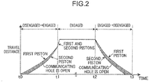
- FIG. 2 is a time chart showing variations in the travel distances of the first and second pistons 14 and 15 during the state transition of the clutch 10 from a disengaged state to an engaged state to a disengaged state.
- the first and second pistons 14 and 15 are at the initial positions (with zero travel distances).
- the communicating hole 14c is slightly open (the valve part 15c is slightly separated from the first piston 14) at this time, connecting the centrifugally balancing chamber 19 with the engaging hydraulic chamber 16.
- the open communicating hole 14c adjusts a difference in hydraulic pressure, if any, between the engaging hydraulic chamber 16 and the centrifugally balancing chamber 19 by allowing the oil flow between the two chambers, which equalizes the hydraulic pressure in the centrifugally balancing chamber 19 with the hydraulic pressure in the engaging hydraulic chamber 16.
- the first and second pistons 14 and 15 are subject to forward pressures due to the difference between the pressure receiving areas on the side of the engaging hydraulic chamber 16 (the areas of the first faces 14 1 and 15 1 ) and the pressure receiving areas on the side of the centrifugally balancing chamber 19 (the areas of the second faces 14 2 and 15 2 ).
- the forward pressures are, however, smaller than the urging forces of the first and second compression springs 17 and 18 at the time t0, so that the first and second pistons 14 and 15 stay at the initial positions at this time.
- the first and second pistons 14 and 15 move from the initial positions to the positions where the front end of the pressing part 14b has zero (clutch) clearance with the friction plates 13 (the latter positions are referred to as "zero clearance positions" hereinafter).
- zero clearance positions Between the starts of movements of the first and second pistons 14 and 15 from the initial positions, there is a time lag due to the different urging forces of the first and second compression springs 17 and 18.
- the first piston 14 first starts to move from the initial position, and then the second piston 15 starts to move from the initial position after a predetermined time lag.
- the time lag causes the first piston 14 to separate from the valve part 15c of the second piston 15, which opens the communicating hole 14c.
- the difference in travel distance between the first and second pistons 14 and 15 gradually decreases as the pistons 14 and 15 come close to the zero clearance positions.
- the first and second pistons 14 and 15 reach the zero clearance positions at the time t1.
- the difference in travel distance between the pistons 14 and 15 becomes zero at this time, when the valve part 15c comes into contact with the first piston 14 and closes the communicating hole 14c again.
- the hydraulic pressure in the engaging hydraulic chamber 16 starts to increase and the increased hydraulic pressure moves the first and second pistons 14 and 15 from the zero clearance positions to engagement completion positions in a short time.
- the pistons 14 and 15 press the friction plates 13 at the maximum pressing force.
- the clutch 10 is thereby engaged and continues to be engaged until a time t2. While the clutch 10 is engaged (from the time t1 to the time t2), the valve part 15c is in contact with the first piston 14 closing the communicating hole 14c.
- the first and second pistons 14 and 15 move from the engagement completion positions to the initial positions. Between the starts of movements of the first and second pistons 14 and 15 from the engagement completion positions, there is a time lag due to the different urging forces of the first and second compression springs 17 and 18. Specifically, since the urging force of the second compression spring 18 is larger than the urging force of the first compression spring 17, the second piston 15 first starts to move from the engagement completion position, and then the first piston 14 starts to move from the engagement completion position after a predetermined time lag.
- the second piston 15 first reaches the initial position, and then the first piston 14 reaches the initial position a little behind.
- the time lag causes the first piston 14 to separate from the valve part 15c of the second piston 15, which opens the communicating hole 14c.
- the difference in travel distance between the first and second pistons 14 and 15 gradually increases as the second piston 15 comes close to the initial position, and the difference gradually decreases after the arrival of the second piston 15 at the initial position.
- both the first and second pistons 14 and 15 have reached the initial positions.
- the communicating hole 14c is slightly open (the valve part 15c is slightly separated from the first piston 14) at this time, as at the time t0, connecting the centrifugally balancing chamber 19 with the engaging hydraulic chamber 16.
- the clutch 10 with the above structure is engaged or disengaged by the hydraulic control mechanism 100 for supplying or discharging hydraulic oil into or from the engaging hydraulic chamber 16 and the centrifugally balancing chamber 19 to control the hydraulic pressures in these chambers.
- the hydraulic control mechanism 100 includes a hydraulic control valve 101 or a solenoid valve, the first oil passage 102, and the second oil passage 104.
- the hydraulic control valve 101 adjusts a line pressure of the hydraulic oil coming in through an input port 101b to an engaging hydraulic pressure and supplies the hydraulic oil at the engaging hydraulic pressure through an output port 101a.
- the first oil passage 102 connects the output port 101a of the hydraulic control valve 101 with the engaging hydraulic chamber 16, and the second oil passage 104 connects the output port 101a with the centrifugally balancing chamber 19 via a reducing valve 103.
- the reducing valve 103 can automatically adjusts a hydraulic pressure at its entrance and a hydraulic pressure at its exit or a drain port 103a by moving its spool to a position for equalizing the urging force of its spring with the hydraulic pressure at the side closer to the centrifugally balancing chamber 19 (the secondary side).
- the reducing valve 103 applies a balancing hydraulic pressure at a predetermined reduced pressure to the centrifugally balancing chamber 19.
- FIG. 3 is a time chart showing variations in the hydraulic pressures applied to the engaging hydraulic chamber 16 and the centrifugally balancing chamber 19, and a variation in the pressing force of the first and second pistons 14 and 15.
- the hydraulic control mechanism 100 continues to increase an equal hydraulic pressure applied to the engaging hydraulic chamber 16 and the centrifugally balancing chamber 19. Accordingly, the hydraulic pressures in the engaging hydraulic chamber 16 and the centrifugally balancing chamber 19 gradually increase to a predetermined balancing hydraulic pressure P0. As the hydraulic pressures in the engaging hydraulic chamber 16 and the centrifugally balancing chamber 19 increase, the pressing force of the first and second pistons 14 and 15 gradually increases.
- the hydraulic control mechanism 100 While the clutch 10 is engaged from the time t1 to the time t2, the hydraulic control mechanism 100 still continues to apply a hydraulic pressure to the engaging hydraulic chamber 16 and the centrifugally balancing chamber 19.
- the hydraulic pressure in the engaging hydraulic chamber 16 continues to gradually increase to a predetermined engaging hydraulic pressure, while the hydraulic pressure in the centrifugally balancing chamber 19 is kept at the predetermined balancing hydraulic pressure P0 by the reducing valve 103.
- the hydraulic pressure in the engaging hydraulic chamber 16 increases, the pressing force of the pistons gradually increases. After a while, the hydraulic pressure in the engaging hydraulic chamber 16 stops increasing and is kept at the predetermined engaging hydraulic pressure, and the pressing force of the pistons is also kept at a predetermined pressing force.
- the hydraulic control mechanism 100 gradually decreases a hydraulic pressure applied to the engaging hydraulic chamber 16 and the centrifugally balancing chamber 19 until the hydraulic pressures in the engaging hydraulic chamber 16 and the centrifugally balancing chamber 19 become zero.
- the hydraulic pressures in the engaging hydraulic chamber 16 and the centrifugally balancing chamber 19 decrease, the pressing force of the first and second pistons 14 and 15 gradually decreases.
- FIG. 4 shows the process of engagement of the clutch 10 from a disengaged state to an engaged state
- FIG. 5 shows the process of disengagement of the clutch 10 from an engaged state to a disengaged state.
- the open communicating hole 14c connects the centrifugally balancing chamber 19 with the engaging hydraulic chamber 16, which equalizes the hydraulic pressure in the centrifugally balancing chamber 19 with the hydraulic pressure in the engaging hydraulic chamber 16 (see the time t0 in FIGS. 2 and 3 , if necessary).
- the first piston 14 Since the urging force of the second compression spring 18 is larger than the urging force of the first compression spring 17, the first piston 14 first starts to move forward, due to the different urging forces, to come close to the zero clearance position (the position where the clutch clearance is substantially zero but the friction plates 13 is not subject to the pressing force of the pistons yet).
- the movement of the first piston 14 away from the valve part 15c of the second piston 15 opens the communicating hole 14c, and the open communicating hole 14c allows the oil flow from the centrifugally balancing chamber 19 to the engaging hydraulic chamber 16 (see the period from the time t0 to the time t1 in FIGS. 2 and 3 , if necessary).
- Chart (a) in FIG. 5 shows the state in which a predetermined engaging hydraulic pressure is applied to the engaging hydraulic chamber 16 and a predetermined balancing hydraulic pressure is applied to the centrifugally balancing chamber 19. Under this condition, the first and second pistons 14 and 15 are pressed forward against the urging forces of the first and second compression springs 17 and 18 (see the time t2 in FIG. 2 ). The first and second pistons 14 and 15 pressing the friction plates 13 keep the clutch 10 engaged (see the time t2 in FIGS. 2 and 3 , if necessary).
- valve part 15c of the second piston 15 moves away from the first piston 14 opening the communicating hole 14c, and the open communicating hole 14c allows the oil flow from the engaging hydraulic chamber 16 to the centrifugally balancing chamber 19 (see the period from the time t2 to the time t3 in FIGS. 2 and 3 , if necessary).
- the first piston 14 then starts to move backward against the urging force of the first compression spring 17.
- chart (c) in FIG. 5 by the time the hydraulic pressures in the engaging hydraulic chamber 16 and the centrifugally balancing chamber 19 are decreased to the point where no hydraulic pressure is applied to these chambers, both the first and second pistons 14 and 15 have reached the initial positions to complete the process of disengagement of the clutch 10.
- the valve part 15c of the second piston 15 is slightly separated from the first piston 14 opening the communicating hole 14c.
- the open communicating hole 14c connects the centrifugally balancing chamber 19 with the engaging hydraulic chamber 16, which equalizes the hydraulic pressure in the centrifugally balancing chamber 19 with the hydraulic pressure in the engaging hydraulic chamber 16 (see the time t3 in FIGS. 2 and 3 , if necessary).
- the first piston 14 has the communicating hole 14c for connecting the engaging hydraulic chamber 16 with the centrifugally balancing chamber 19
- the second piston 15 has the valve part 15c for closing the communicating hole 14c
- the first and second compression springs 17 and 18 have different urging forces so that the difference in travel distance between the first and second pistons 14 and 15 in motion due to the different urging forces of the first and second compression springs 17 and 18 causes the valve part 15c to open the communicating hole 14c.
- the second piston 15 In the process of disengagement of the clutch 10, the second piston 15 first starts to move backward (in the direction of releasing the friction plates 13) as the hydraulic pressure in the engaging hydraulic chamber 16 decreases. For a short time after the start of the movement of the second piston 15, the second piston 15 moves away from the first piston 14 in the axial direction, which causes the valve part 15c to open the communicating hole 14c.
- the open communicating hole 14c allows the oil flow from the engaging hydraulic chamber 16 to the centrifugally balancing chamber 19.
- the hydraulic oil in the engaging hydraulic chamber 16 is discharged through the communicating hole 14c as well as by the hydraulic control mechanism 100. This shortens a time for discharging hydraulic oil, that is, a switch time for disengaging the clutch 10.
- the first embodiment facilitates the discharge of hydraulic oil from the engaging hydraulic chamber 16 to shorten a switch time for disengaging the frictional element 10 in the process of disengagement of the clutch 10.
- the first and second compression springs 17 and 18 of the pistons 14 and 15 are disposed in the centrifugally balancing chamber 19. These compression springs are easier to be mounted than extension coil springs.
- the automatic transmission 1 further includes the hydraulic control mechanism 100 having the hydraulic control valve 101 for controlling the clutch 10, the first oil passage 102 for connecting the output port 101a of the hydraulic pressure valve 101 and the engaging hydraulic chamber 16, and the second oil passage 104 for connecting the output port 101a and the centrifugally balancing chamber 19.
- the single hydraulic control valve 101 efficiently supplies hydraulic oil to both the engaging hydraulic chamber 16 and the centrifugally balancing chamber 19 to achieve a necessary hydraulic pressure.
- the automatic transmission 1 further includes the reducing valve 103 on the second oil passage 104.
- the reducing valve 103 restricts the hydraulic pressure in the centrifugally balancing chamber 19 to a predetermined pressure. While the clutch 10 is engaged, the reducing valve 103 properly keeps the hydraulic pressure in the centrifugally balancing chamber 19 lower than the hydraulic pressure in the engaging hydraulic chamber 16 to ensure an engaging hydraulic pressure necessary for keeping the clutch 10 engaged.
- the first and second pistons 14 and 15 have the first faces 14 1 and 15 1 larger than the second faces 14 2 and 15 2 so that there is a difference in pressure receiving area between the first and second faces. Even when there is little difference in hydraulic pressure between the engaging hydraulic chamber 16 and the centrifugally balancing chamber 19, for example, in the case without the reducing valve 103 or when the reducing valve 103 has not yet achieved a substantial pressure reduction shortly after the start of control; the difference in pressure receiving area enables the first and second pistons 14 and 15 to move forward (in the direction of pressing the friction plates 13) against the first and second compression springs 17 and 18 in the process of engagement of the clutch 10.
- FIG. 6 is a cross-sectional view of a frictional engagement element of an automatic transmission according to a second embodiment of the present invention.
- the second embodiment is different from the first embodiment in the position of the communicating hole for connecting the engaging hydraulic chamber with the centrifugally balancing chamber and the position of the valve part for opening or closing the communicating hole.
- the same reference numerals will be used for the same structural elements as the structural elements of the first embodiment, and detailed descriptions on those structural elements will be omitted.
- the hydraulic pressure receiving part 15a of the second piston 15 has the communicating hole 115c for connecting the engaging hydraulic chamber 16 with the centrifugally balancing chamber 19.
- the valve part 114c for opening or closing the communicating hole 115c extends inward from the hydraulic pressure receiving part 14a of the first piston 14 in the radial direction.
- the valve part 114c is disposed in the centrifugally balancing chamber 19 and configured to close the opening at the forward side (the side closer to the friction plates 13) of the communicating hole 115c in the hydraulic pressure receiving part 15a.
- the second piston 15 in the process of disengagement of the clutch, the second piston 15 first starts to move from the zero clearance position toward the initial position as the hydraulic pressure in the engaging hydraulic chamber 16 decreases, as in the first embodiment.
- the second piston 15 moves away from the first piston 14 in the axial direction, which causes the valve part 114c to open the communicating hole 115c.
- the open communicating hole 115c allows the oil flow from the engaging hydraulic chamber 16 to the centrifugally balancing chamber 19.
- the hydraulic oil in the engaging hydraulic chamber 16 is discharged through the communicating hole 115c as well as by the hydraulic control mechanism 100. This shortens a time for discharging hydraulic oil from the engaging hydraulic chamber 16, that is, a switch time for disengaging the clutch 10.
- the second embodiment facilitates the discharge of hydraulic oil from the engaging hydraulic chamber 16 to shorten a switch time for disengaging the frictional element 10 in the process of disengagement of the clutch 10, as in the first embodiment.
- FIGS. 7 and 8 are cross-sectional views of modified embodiments of the frictional engagement element.
- the same reference numerals will be used for the same structural elements as the structural elements of the first embodiment, and detailed descriptions on those structural elements will be omitted.
- the centrifugally balancing chamber 19 may not be subject to a balancing hydraulic pressure generated by the hydraulic control mechanism 100, but may be supplied with some of lubricating oil for generating a balancing hydraulic pressure through a lubricating oil passage 114 for supplying the lubricating oil to gears, bearings and the like in the automatic transmission 1.
- the first piston 14 may have an air hole 30.
- the air hole 30 extends in the hydraulic pressure receiving part 14a of the first piston 14 in the radial direction.
- One end of the air hole 30 (the opening at the inner side) is connected with a space 31 defined by the first and second pistons 14 and 15, and the other end of the air hole 30 (the opening at the outer side) is connected with the space defined by the outer surface of the first piston 14 and the outer cylinder part 12a of the drum 12.
- the space 31 is isolated from the engaging hydraulic chamber 16 and the centrifugally balancing chamber 19 by sealing members 21b and 21c disposed between the first and second pistons 14 and 15.
- the air hole 30 leads some of the pressurized air to the outside space (the space between the first piston 14 and the outer cylinder part 12a), which prevents an undesirable air pressure increase in the space 31 in order to prevent the pressurized air in the space 31 from going through the gaps at the sealing members 21b and 21c (the small gaps between the sealing members 21b and 21c and their contact surfaces) into the engaging hydraulic chamber 16 or the centrifugally balancing chamber 19.
- the air hole 30 is formed in the first piston 14 in order to lead some of the air in the space 31 to a space other than the hydraulic chambers.
- the air hole may be formed in the second piston 15.
- the frictional engagement element is the clutch 10, however, the frictional engagement element is not limited to this and may be a brake.
- the frictional engagement element is a brake, parts of the friction plates are fixed not to the drum but to a transmission casing in a fixed position or the like, and the centrifugally balancing chamber 19 is replaced with a disengaging hydraulic pressure chamber.
- valve part 15c (114c) may be disposed at any position as long as the valve part 15c (114c) can cover the communicating hole 14c (115c).
- the valve part 15c may be provided all around the circumference of the hydraulic pressure receiving part 15a as well as protrude outward from a portion of the circumference of the hydraulic pressure receiving part 15a in the radial direction to close the communicating hole 14c. This is also the case for the valve part 114c in a modified embodiment based on the second embodiment.
- the present invention is applied to a vehicle including the multistage automatic transmission 1 having planetary gear mechanisms, however, the present invention can be applied to other types of vehicles such as a vehicle having a continuously variable transmission (CVT) and a hybrid electric vehicle (HEV) having a clutch for intermittently transmitting the power of the engine.
- CVT continuously variable transmission
- HEV hybrid electric vehicle
- the above embodiments relate to a frictional engagement element or an automatic transmission including the frictional engagement element.
- the frictional engagement element includes: a first piston and a second piston each having a first face and a second face opposite to each other in the axial direction, the first and second pistons being movable in an axial direction; a plurality of friction plates disposed near the second faces of the first and second pistons; an engaging hydraulic chamber defined by the first faces of the first and second pistons, the engaging hydraulic chamber being configured to be subject to a hydraulic pressure to move the first and second pistons in a direction of pressing the friction plates; an opposite hydraulic chamber defined by the second faces of the first and second pistons, the opposite hydraulic chamber being configured to be subject to a hydraulic pressure to move the first and second pistons in a direction of releasing the friction plates; a first urging member for urging the first piston in the direction of releasing the friction plates; and a second urging member for urging the second piston in the direction of releasing the friction plates with an urging force larger than the urging force of
- One of the first and second pistons has a communicating hole for connecting the engaging hydraulic chamber with the opposite hydraulic chamber and the other of the first and second pistons has a valve part for closing the communicating hole.
- the first and second urging members have different urging forces so that a difference in travel distance between the first and second pistons in motion due to the different urging forces of the first and second urging members causes the valve part to open the communicating hole.
- one of the first and second pistons has the communicating hole for connecting the engaging hydraulic chamber with the opposite hydraulic chamber
- the other of the first and second pistons has the valve part for closing the communicating hole
- the first and second urging members have different urging forces so that the difference in travel distance between the first and second pistons in motion due to the different urging forces of the first and second urging members causes the valve part to open the communicating hole.
- the second piston first starts to move in the disengagement direction as the hydraulic pressure in the engaging hydraulic chamber decreases.
- the second piston moves away from the first piston in the axial direction, which causes the valve part to open the communicating hole. Accordingly, the hydraulic oil in the engaging hydraulic chamber is discharged through the communicating hole as well as by the hydraulic control mechanism.
- the embodiments facilitate the discharge of hydraulic oil from the engaging hydraulic chamber to shorten a switch time for disengaging the frictional engagement element in the process of disengagement of the frictional element.
- the first and second urging members should preferably be disposed in the opposite hydraulic chamber.
- the first and second urging members in the opposite hydraulic chamber may be compression urging members such as disc springs, leaf springs, and compression coil springs. These types of urging members are easier to be mounted than tension urging members such as extension coil springs.
- the automatic transmission should preferably further include the hydraulic control mechanism.
- the hydraulic control mechanism includes: the hydraulic control valve for controlling the frictional engagement element; the first oil passage for connecting the output port of the hydraulic control valve with the engaging hydraulic chamber; and the second oil passage for connecting the output port with the opposite hydraulic chamber.
- the single hydraulic control valve in this structure efficiently supply hydraulic oil to both the engaging hydraulic chamber and the opposite hydraulic chamber to achieve a necessary hydraulic pressure.
- each of the first and second pistons should more preferably have the first face larger than the second face.
- the difference in pressure receiving area enables the first and second pistons to move against the first and second urging members in the process of engagement of the frictional engagement element.
- the automatic transmission should more preferably further include the reducing valve on the second oil passage.
- the reducing valve restricts the hydraulic pressure in the opposite hydraulic chamber to a predetermined pressure.
- the reducing valve properly keeps the hydraulic pressure in the opposite hydraulic chamber lower than the hydraulic pressure in the engaging hydraulic chamber to ensure an engaging hydraulic pressure necessary for keeping the frictional engagement element engaged.
- a space is disposed between the first and second pistons, the space should be isolated from the engaging hydraulic chamber and the opposite hydraulic chamber, and an air hole extends in the first piston or in the second piston, the air hole should be configured to lead some of the air in the space to an outside space.
- the air hole in the first piston or the second piston leads some of the pressurized air to the outside space, which prevents an undesirable air pressure increase in the space in order to prevent an undesirable air invasion into the engaging hydraulic chamber or the opposite hydraulic chamber.
- the present invention relates to the frictional engagement element having the engaging hydraulic chamber opposite to the opposite hydraulic chamber (such as a centrifugally balancing chamber or a disengaging hydraulic chamber) with the pistons therebetween, and the automatic transmission including the frictional engagement element.
- the embodiments of the present invention facilitate the discharge of hydraulic oil from the engaging hydraulic chamber to shorten a switch time for disengaging the frictional element.
- the present invention is thus advantageously used in the technical field for manufacturing automatic transmissions including the frictional engagement elements and vehicles including the automatic transmissions.
Landscapes
- Engineering & Computer Science (AREA)
- General Engineering & Computer Science (AREA)
- Mechanical Engineering (AREA)
- Physics & Mathematics (AREA)
- Fluid Mechanics (AREA)
- Hydraulic Clutches, Magnetic Clutches, Fluid Clutches, And Fluid Joints (AREA)
- Gear-Shifting Mechanisms (AREA)
- Control Of Transmission Device (AREA)
Claims (6)
- Automatisches Getriebe (1) umfassend ein Reibschlusselement (10), wobei das Reibschlusselement (10) umfasst:einen ersten Kolben (14) und einen zweiten Kolben (15), die beide jeweils eine erste Fläche (141, 151) und eine zweite Fläche (142, 152) in axialer Richtung einander gegenüberliegend aufweisen, wobei der erste und der zweite Kolben (14, 15) in axialer Richtung bewegbar bzw. verfahrbar sind;eine Vielzahl von Reibungsplatten (13), die nahe den zweiten Flächen (142, 152) des ersten und des zweiten Kolbens (14, 15) angeordnet sind;eine Eingriffshydraulikkammer (16), definiert von den ersten Flächen (141, 151) des ersten und des zweiten Kolbens (14, 15), wobei die Eingriffshydraulikkammer (16) so konfiguriert ist, dass ein hydraulischer Druck auf sie einwirkt, um den ersten und den zweiten Kolben (14, 15) in eine Richtung des Pressens der Reibungsplatten (13) zu bewegen;eine entgegengesetzte bzw. gegenüberliegende Hydraulikkammer (19), umgrenzt von den zweiten Flächen (142, 152) des ersten und des zweiten Kolbens (14, 15), wobei die gegenüberliegende Hydraulikkammer (19) so konfiguriert ist, dass ein hydraulischer Druck auf sie einwirkt, um den ersten und den zweiten Kolben (14, 15) in eine Richtung des Freigebens der Reibungsplatten (13) zu bewegen;ein erstes Treib- bzw. Druckglied (17), um den ersten Kolben (14) in die Richtung zu treiben, in der die Reibungsplatten (13) entlastet werden; undein zweites Treib- bzw. Druckglied (18), um den zweiten Kolben (15) in die Richtung zu treiben, in der die Reibungsplatten (13) entlastet werden mit einer Treib- bzw. Druckkraft, die größer ist als die Treib- bzw. Druckkraft des ersten Treib- bzw. Druckglieds (17),wobei einer von dem ersten und dem zweiten Kolben (14, 15) eine Verbindungsöffnung (14c; 115c) zum Verbinden der Eingriffshydraulikkammer (16) mit der gegenüberliegenden Hydraulikkammer (19) aufweist und der andere von dem ersten und dem zweiten Kolben (14, 15) ein Ventilteil (15c; 114c) zum Schließen der Verbindungssöffnung (14c; 115c) aufweist,
das erste und das zweite Treib- bzw. Druckglied (17, 18) unterschiedliche Treib- bzw. Druckkräfte aufweisen, sodass während des Auskupplungsvorgangs des Reibschlusselements (10) ein Unterschied zwischen den Verfahrwegsdistanzen des ersten und des zweiten Kolbens (14, 15) in Bewegung aufgrund der unterschiedlichen Treib- bzw. Druckkräfte des ersten und des zweiten Treib- bzw. Druckglieds (17, 18) dazu führt, dass das Ventilteil (15c; 114c) die Verbindungsöffnung (14c; 115c) öffnet, so dass hydraulisches Öl von der Eingriffshydraulikkammer (16) in die gegenüberliegende Hydraulikkammer (19) durch die Verbindungsöffnung (14c; 115c) fließt, und
das erste und das zweite Treib- bzw. Druckglied (17, 18) unterschiedliche Treib- bzw. Druckkräfte aufweisen, sodass während des Kupplungsvorgangs des Reibschlusselements (10) ein Unterschied zwischen den Verfahrwegsdistanzen des ersten und des zweiten Kolbens (14, 15) in Bewegung aufgrund der unterschiedlichen Treib- bzw. Druckkräfte des ersten und des zweiten Treib- bzw. Druckglieds (17, 18) dazu führt, dass das Ventilteil (15c; 114c) die Verbindungsöffnung (14c; 115c) öffnet, so dass hydraulisches Öl von der gegenüberliegenden Hydraulikkammer (19) in die Eingriffshydraulikkammer (16) durch die Verbindungsöffnung (14c; 115c) fließt. - Automatisches Getriebe nach Anspruch 1, wobei
das erste und das zweite Treib- bzw. Druckglied (17, 18) in der gegenüberliegenden Hydraulikkammer (19) angeordnet sind. - Automatisches Getriebe nach einem der Ansprüche 1 und 2,
wobei das automatische Getriebe (1) außerdem einen hydraulischen Steuer- bzw. Regelmechanismus (100) umfasst,
wobei der hydraulische Steuer- bzw. Regelmechanismus (100) beinhaltet: ein hydraulisches Steuer- bzw. Regelventil (101) zum Steuern bzw. Regeln des Reibschlusselements (10); ein erster Öldurchgang (102) zum Verbinden von einer Auslassöffnung (101a) des hydraulischen Steuer- bzw. Regelventils (101) mit der Eingriffshydraulikkammer (16); und ein zweiter Öldurchgang (104) zum Verbinden der Auslassöffnung (101a) mit der gegenüberliegenden Hydraulikkammer (19). - Automatisches Getriebe nach Anspruch 3, wobei
sowohl bei dem ersten als auch bei dem zweiten Kolben (14, 15) jeweils die erste Fläche (141, 151) größer ist als die zweite Fläche (142, 152). - Automatisches Getriebe nach einem der Ansprüche 3 und 4,
wobei das automatische Getriebe (1) außerdem ein Reduzierventil bzw. ein Druckminderventil (103) an dem zweiten Öldurchgang (104) umfasst, wobei das Druckminderventil (103) so konfiguriert ist, dass es den hydraulischen Druck in der gegenüberliegenden Hydraulikkammer (19) auf einen vorgegebenen Druck begrenzt. - Automatisches Getriebe nach einem der Ansprüche 1 bis 5, wobei
ein Raum (31) zwischen dem ersten und dem zweiten Kolben (14, 15) angeordnet ist, wobei der Raum (31) von der Eingriffshydraulikkammer (16) und der gegenüberliegenden Hydraulikkammer (19) isoliert ist und sich ein Luftloch (30) in dem ersten Kolben (14) oder in dem zweiten Kolben (15) erstreckt, wobei das Luftloch (30) so konfiguriert ist, dass es einen Teil der Luft in dem Raum (31) in einen äußeren Raum leitet.
Applications Claiming Priority (2)
| Application Number | Priority Date | Filing Date | Title |
|---|---|---|---|
| JP2016066371 | 2016-03-29 | ||
| PCT/JP2017/011229 WO2017169980A1 (ja) | 2016-03-29 | 2017-03-21 | 自動変速機及び摩擦締結要素 |
Publications (3)
| Publication Number | Publication Date |
|---|---|
| EP3415795A1 EP3415795A1 (de) | 2018-12-19 |
| EP3415795A4 EP3415795A4 (de) | 2019-03-20 |
| EP3415795B1 true EP3415795B1 (de) | 2020-03-04 |
Family
ID=59965272
Family Applications (1)
| Application Number | Title | Priority Date | Filing Date |
|---|---|---|---|
| EP17774521.3A Active EP3415795B1 (de) | 2016-03-29 | 2017-03-21 | Automatikgetriebe und reibschlusselement |
Country Status (5)
| Country | Link |
|---|---|
| US (1) | US10767706B2 (de) |
| EP (1) | EP3415795B1 (de) |
| JP (1) | JP6737331B2 (de) |
| CN (1) | CN108884934B (de) |
| WO (1) | WO2017169980A1 (de) |
Families Citing this family (6)
| Publication number | Priority date | Publication date | Assignee | Title |
|---|---|---|---|---|
| JP6330852B2 (ja) * | 2016-02-23 | 2018-05-30 | マツダ株式会社 | 自動変速機 |
| EP3339670A1 (de) * | 2016-12-22 | 2018-06-27 | Dana Belgium N.V. | Nasskupplungsanordnung |
| DE102017211264A1 (de) * | 2017-07-03 | 2019-01-03 | Zf Friedrichshafen Ag | Torsionsdämpfungsanordnung sowie Kraftfahrzeug |
| KR102487176B1 (ko) * | 2017-12-11 | 2023-01-10 | 현대자동차 주식회사 | 자동변속기용 동력전달장치 |
| KR102589912B1 (ko) * | 2018-07-16 | 2023-10-13 | 현대자동차 주식회사 | 자동변속기용 동력전달장치 |
| US11236786B2 (en) * | 2020-01-09 | 2022-02-01 | Cnh Industrial America Llc | Multipart balanced piston clutch |
Family Cites Families (16)
| Publication number | Priority date | Publication date | Assignee | Title |
|---|---|---|---|---|
| US3690429A (en) * | 1971-07-15 | 1972-09-12 | Honda Motor Co Ltd | Clutch with dual pistons and springs |
| JPS5714807B2 (de) | 1974-02-18 | 1982-03-26 | ||
| JPS5439720Y2 (de) * | 1974-02-20 | 1979-11-24 | ||
| US4020933A (en) * | 1975-08-28 | 1977-05-03 | Westinghouse Air Brake Company | Fluid operated clutch with dual pistons |
| GB8811377D0 (en) | 1988-05-13 | 1988-06-15 | Vidal H | Joining of concrete element to support |
| JPH0543296Y2 (de) * | 1988-08-11 | 1993-11-01 | ||
| JPH05340430A (ja) | 1992-06-05 | 1993-12-21 | Mazda Motor Corp | 油圧クラッチ装置 |
| JP3033381B2 (ja) | 1993-03-08 | 2000-04-17 | 日産自動車株式会社 | 自動変速機の回転クラッチ |
| JP3625591B2 (ja) * | 1996-10-31 | 2005-03-02 | ジヤトコ株式会社 | 自動変速機の締結装置 |
| JP2002257219A (ja) | 2001-02-27 | 2002-09-11 | Aisin Seiki Co Ltd | 自動変速機の油圧制御装置 |
| JP5315375B2 (ja) | 2011-03-29 | 2013-10-16 | ジヤトコ株式会社 | 多板式摩擦係合機構 |
| KR101827006B1 (ko) | 2012-08-10 | 2018-02-07 | 현대자동차주식회사 | 자동변속기의 클러치 유로 공기빼기 장치 |
| KR101875624B1 (ko) | 2012-09-21 | 2018-07-06 | 현대자동차 주식회사 | 더블 피스톤 유압 시스템 |
| US9458896B2 (en) | 2014-02-28 | 2016-10-04 | C-Stone Technologies Co., Ltd. | Power transmission device provided with more than two pistons and method of determining return spring force in the same |
| JP6384099B2 (ja) | 2014-04-18 | 2018-09-05 | いすゞ自動車株式会社 | デュアルクラッチ装置 |
| JP6215780B2 (ja) | 2014-06-12 | 2017-10-18 | 本田技研工業株式会社 | 油圧クラッチ装置 |
-
2017
- 2017-03-21 US US15/761,685 patent/US10767706B2/en active Active
- 2017-03-21 CN CN201780017992.0A patent/CN108884934B/zh active Active
- 2017-03-21 EP EP17774521.3A patent/EP3415795B1/de active Active
- 2017-03-21 WO PCT/JP2017/011229 patent/WO2017169980A1/ja not_active Ceased
- 2017-03-21 JP JP2018509090A patent/JP6737331B2/ja active Active
Non-Patent Citations (1)
| Title |
|---|
| None * |
Also Published As
| Publication number | Publication date |
|---|---|
| US20180347639A1 (en) | 2018-12-06 |
| CN108884934B (zh) | 2020-06-12 |
| EP3415795A1 (de) | 2018-12-19 |
| JP6737331B2 (ja) | 2020-08-05 |
| JPWO2017169980A1 (ja) | 2019-02-07 |
| WO2017169980A1 (ja) | 2017-10-05 |
| EP3415795A4 (de) | 2019-03-20 |
| US10767706B2 (en) | 2020-09-08 |
| CN108884934A (zh) | 2018-11-23 |
Similar Documents
| Publication | Publication Date | Title |
|---|---|---|
| EP3415795B1 (de) | Automatikgetriebe und reibschlusselement | |
| CN104718393B (zh) | 变速器的制动装置及其控制系统 | |
| US20140076680A1 (en) | Lock-up device for torque converter | |
| US20150141189A1 (en) | Friction engagement device | |
| CN104685250A (zh) | 自动变速器的摩擦联接元件的润滑构造 | |
| JP5541259B2 (ja) | 油圧クラッチおよびそれを備えた変速装置 | |
| US20070267265A1 (en) | Clutch arrangement | |
| JP6003516B2 (ja) | 自動変速機 | |
| JP6330852B2 (ja) | 自動変速機 | |
| JP5447422B2 (ja) | 油圧クラッチおよびそれを備えた変速装置 | |
| WO2012132915A1 (ja) | 変速装置 | |
| KR101820516B1 (ko) | 두 개 이상의 피스톤이 구비된 동력 전달 장치 및 리턴 스프링 하중을 결정하는 방법 | |
| US9080615B2 (en) | Transmission device | |
| JP2006300266A (ja) | 自動変速機の湿式クラッチ装置 | |
| KR102487176B1 (ko) | 자동변속기용 동력전달장치 | |
| EP3757415B1 (de) | Reibungskupplung | |
| JP6278092B1 (ja) | 自動変速機の摩擦締結装置 | |
| JP6119485B2 (ja) | 変速機のブレーキ装置 | |
| KR101827006B1 (ko) | 자동변속기의 클러치 유로 공기빼기 장치 | |
| KR20160065252A (ko) | 변속 제어 장치 | |
| JPWO2014050727A1 (ja) | 自動変速機及びその制御方法 | |
| JP6119484B2 (ja) | 変速機のブレーキ装置 | |
| KR20080041885A (ko) | 차량용 자동 변속기 | |
| JP2017067222A (ja) | 自動変速機 | |
| KR20160071520A (ko) | 변속 제어 장치 |
Legal Events
| Date | Code | Title | Description |
|---|---|---|---|
| STAA | Information on the status of an ep patent application or granted ep patent |
Free format text: STATUS: THE INTERNATIONAL PUBLICATION HAS BEEN MADE |
|
| PUAI | Public reference made under article 153(3) epc to a published international application that has entered the european phase |
Free format text: ORIGINAL CODE: 0009012 |
|
| STAA | Information on the status of an ep patent application or granted ep patent |
Free format text: STATUS: REQUEST FOR EXAMINATION WAS MADE |
|
| 17P | Request for examination filed |
Effective date: 20180913 |
|
| AK | Designated contracting states |
Kind code of ref document: A1 Designated state(s): AL AT BE BG CH CY CZ DE DK EE ES FI FR GB GR HR HU IE IS IT LI LT LU LV MC MK MT NL NO PL PT RO RS SE SI SK SM TR |
|
| AX | Request for extension of the european patent |
Extension state: BA ME |
|
| RIC1 | Information provided on ipc code assigned before grant |
Ipc: F16D 25/0638 20060101ALI20190207BHEP Ipc: F16H 63/30 20060101AFI20190207BHEP |
|
| A4 | Supplementary search report drawn up and despatched |
Effective date: 20190220 |
|
| DAV | Request for validation of the european patent (deleted) | ||
| DAX | Request for extension of the european patent (deleted) | ||
| GRAP | Despatch of communication of intention to grant a patent |
Free format text: ORIGINAL CODE: EPIDOSNIGR1 |
|
| STAA | Information on the status of an ep patent application or granted ep patent |
Free format text: STATUS: GRANT OF PATENT IS INTENDED |
|
| RIC1 | Information provided on ipc code assigned before grant |
Ipc: F16H 61/02 20060101ALI20190912BHEP Ipc: F16D 25/0638 20060101ALI20190912BHEP Ipc: F16H 63/30 20060101AFI20190912BHEP |
|
| INTG | Intention to grant announced |
Effective date: 20191010 |
|
| GRAS | Grant fee paid |
Free format text: ORIGINAL CODE: EPIDOSNIGR3 |
|
| GRAA | (expected) grant |
Free format text: ORIGINAL CODE: 0009210 |
|
| STAA | Information on the status of an ep patent application or granted ep patent |
Free format text: STATUS: THE PATENT HAS BEEN GRANTED |
|
| AK | Designated contracting states |
Kind code of ref document: B1 Designated state(s): AL AT BE BG CH CY CZ DE DK EE ES FI FR GB GR HR HU IE IS IT LI LT LU LV MC MK MT NL NO PL PT RO RS SE SI SK SM TR |
|
| REG | Reference to a national code |
Ref country code: GB Ref legal event code: FG4D |
|
| REG | Reference to a national code |
Ref country code: CH Ref legal event code: EP |
|
| REG | Reference to a national code |
Ref country code: AT Ref legal event code: REF Ref document number: 1240752 Country of ref document: AT Kind code of ref document: T Effective date: 20200315 |
|
| REG | Reference to a national code |
Ref country code: DE Ref legal event code: R096 Ref document number: 602017012698 Country of ref document: DE |
|
| REG | Reference to a national code |
Ref country code: IE Ref legal event code: FG4D |
|
| PG25 | Lapsed in a contracting state [announced via postgrant information from national office to epo] |
Ref country code: RS Free format text: LAPSE BECAUSE OF FAILURE TO SUBMIT A TRANSLATION OF THE DESCRIPTION OR TO PAY THE FEE WITHIN THE PRESCRIBED TIME-LIMIT Effective date: 20200304 Ref country code: FI Free format text: LAPSE BECAUSE OF FAILURE TO SUBMIT A TRANSLATION OF THE DESCRIPTION OR TO PAY THE FEE WITHIN THE PRESCRIBED TIME-LIMIT Effective date: 20200304 Ref country code: NO Free format text: LAPSE BECAUSE OF FAILURE TO SUBMIT A TRANSLATION OF THE DESCRIPTION OR TO PAY THE FEE WITHIN THE PRESCRIBED TIME-LIMIT Effective date: 20200604 |
|
| REG | Reference to a national code |
Ref country code: NL Ref legal event code: MP Effective date: 20200304 |
|
| PG25 | Lapsed in a contracting state [announced via postgrant information from national office to epo] |
Ref country code: HR Free format text: LAPSE BECAUSE OF FAILURE TO SUBMIT A TRANSLATION OF THE DESCRIPTION OR TO PAY THE FEE WITHIN THE PRESCRIBED TIME-LIMIT Effective date: 20200304 Ref country code: LV Free format text: LAPSE BECAUSE OF FAILURE TO SUBMIT A TRANSLATION OF THE DESCRIPTION OR TO PAY THE FEE WITHIN THE PRESCRIBED TIME-LIMIT Effective date: 20200304 Ref country code: SE Free format text: LAPSE BECAUSE OF FAILURE TO SUBMIT A TRANSLATION OF THE DESCRIPTION OR TO PAY THE FEE WITHIN THE PRESCRIBED TIME-LIMIT Effective date: 20200304 Ref country code: GR Free format text: LAPSE BECAUSE OF FAILURE TO SUBMIT A TRANSLATION OF THE DESCRIPTION OR TO PAY THE FEE WITHIN THE PRESCRIBED TIME-LIMIT Effective date: 20200605 Ref country code: BG Free format text: LAPSE BECAUSE OF FAILURE TO SUBMIT A TRANSLATION OF THE DESCRIPTION OR TO PAY THE FEE WITHIN THE PRESCRIBED TIME-LIMIT Effective date: 20200604 |
|
| REG | Reference to a national code |
Ref country code: LT Ref legal event code: MG4D |
|
| PG25 | Lapsed in a contracting state [announced via postgrant information from national office to epo] |
Ref country code: NL Free format text: LAPSE BECAUSE OF FAILURE TO SUBMIT A TRANSLATION OF THE DESCRIPTION OR TO PAY THE FEE WITHIN THE PRESCRIBED TIME-LIMIT Effective date: 20200304 |
|
| PG25 | Lapsed in a contracting state [announced via postgrant information from national office to epo] |
Ref country code: CZ Free format text: LAPSE BECAUSE OF FAILURE TO SUBMIT A TRANSLATION OF THE DESCRIPTION OR TO PAY THE FEE WITHIN THE PRESCRIBED TIME-LIMIT Effective date: 20200304 Ref country code: RO Free format text: LAPSE BECAUSE OF FAILURE TO SUBMIT A TRANSLATION OF THE DESCRIPTION OR TO PAY THE FEE WITHIN THE PRESCRIBED TIME-LIMIT Effective date: 20200304 Ref country code: IS Free format text: LAPSE BECAUSE OF FAILURE TO SUBMIT A TRANSLATION OF THE DESCRIPTION OR TO PAY THE FEE WITHIN THE PRESCRIBED TIME-LIMIT Effective date: 20200704 Ref country code: SK Free format text: LAPSE BECAUSE OF FAILURE TO SUBMIT A TRANSLATION OF THE DESCRIPTION OR TO PAY THE FEE WITHIN THE PRESCRIBED TIME-LIMIT Effective date: 20200304 Ref country code: ES Free format text: LAPSE BECAUSE OF FAILURE TO SUBMIT A TRANSLATION OF THE DESCRIPTION OR TO PAY THE FEE WITHIN THE PRESCRIBED TIME-LIMIT Effective date: 20200304 Ref country code: LT Free format text: LAPSE BECAUSE OF FAILURE TO SUBMIT A TRANSLATION OF THE DESCRIPTION OR TO PAY THE FEE WITHIN THE PRESCRIBED TIME-LIMIT Effective date: 20200304 Ref country code: EE Free format text: LAPSE BECAUSE OF FAILURE TO SUBMIT A TRANSLATION OF THE DESCRIPTION OR TO PAY THE FEE WITHIN THE PRESCRIBED TIME-LIMIT Effective date: 20200304 Ref country code: PT Free format text: LAPSE BECAUSE OF FAILURE TO SUBMIT A TRANSLATION OF THE DESCRIPTION OR TO PAY THE FEE WITHIN THE PRESCRIBED TIME-LIMIT Effective date: 20200729 Ref country code: SM Free format text: LAPSE BECAUSE OF FAILURE TO SUBMIT A TRANSLATION OF THE DESCRIPTION OR TO PAY THE FEE WITHIN THE PRESCRIBED TIME-LIMIT Effective date: 20200304 |
|
| REG | Reference to a national code |
Ref country code: CH Ref legal event code: PL |
|
| REG | Reference to a national code |
Ref country code: AT Ref legal event code: MK05 Ref document number: 1240752 Country of ref document: AT Kind code of ref document: T Effective date: 20200304 |
|
| REG | Reference to a national code |
Ref country code: DE Ref legal event code: R097 Ref document number: 602017012698 Country of ref document: DE |
|
| REG | Reference to a national code |
Ref country code: BE Ref legal event code: MM Effective date: 20200331 |
|
| PG25 | Lapsed in a contracting state [announced via postgrant information from national office to epo] |
Ref country code: MC Free format text: LAPSE BECAUSE OF FAILURE TO SUBMIT A TRANSLATION OF THE DESCRIPTION OR TO PAY THE FEE WITHIN THE PRESCRIBED TIME-LIMIT Effective date: 20200304 Ref country code: LU Free format text: LAPSE BECAUSE OF NON-PAYMENT OF DUE FEES Effective date: 20200321 |
|
| PLBE | No opposition filed within time limit |
Free format text: ORIGINAL CODE: 0009261 |
|
| STAA | Information on the status of an ep patent application or granted ep patent |
Free format text: STATUS: NO OPPOSITION FILED WITHIN TIME LIMIT |
|
| PG25 | Lapsed in a contracting state [announced via postgrant information from national office to epo] |
Ref country code: CH Free format text: LAPSE BECAUSE OF NON-PAYMENT OF DUE FEES Effective date: 20200331 Ref country code: LI Free format text: LAPSE BECAUSE OF NON-PAYMENT OF DUE FEES Effective date: 20200331 Ref country code: IE Free format text: LAPSE BECAUSE OF NON-PAYMENT OF DUE FEES Effective date: 20200321 Ref country code: IT Free format text: LAPSE BECAUSE OF FAILURE TO SUBMIT A TRANSLATION OF THE DESCRIPTION OR TO PAY THE FEE WITHIN THE PRESCRIBED TIME-LIMIT Effective date: 20200304 Ref country code: AT Free format text: LAPSE BECAUSE OF FAILURE TO SUBMIT A TRANSLATION OF THE DESCRIPTION OR TO PAY THE FEE WITHIN THE PRESCRIBED TIME-LIMIT Effective date: 20200304 Ref country code: DK Free format text: LAPSE BECAUSE OF FAILURE TO SUBMIT A TRANSLATION OF THE DESCRIPTION OR TO PAY THE FEE WITHIN THE PRESCRIBED TIME-LIMIT Effective date: 20200304 |
|
| 26N | No opposition filed |
Effective date: 20201207 |
|
| PG25 | Lapsed in a contracting state [announced via postgrant information from national office to epo] |
Ref country code: BE Free format text: LAPSE BECAUSE OF NON-PAYMENT OF DUE FEES Effective date: 20200331 Ref country code: SI Free format text: LAPSE BECAUSE OF FAILURE TO SUBMIT A TRANSLATION OF THE DESCRIPTION OR TO PAY THE FEE WITHIN THE PRESCRIBED TIME-LIMIT Effective date: 20200304 Ref country code: PL Free format text: LAPSE BECAUSE OF FAILURE TO SUBMIT A TRANSLATION OF THE DESCRIPTION OR TO PAY THE FEE WITHIN THE PRESCRIBED TIME-LIMIT Effective date: 20200304 |
|
| PG25 | Lapsed in a contracting state [announced via postgrant information from national office to epo] |
Ref country code: FR Free format text: LAPSE BECAUSE OF NON-PAYMENT OF DUE FEES Effective date: 20200504 |
|
| GBPC | Gb: european patent ceased through non-payment of renewal fee |
Effective date: 20210321 |
|
| PG25 | Lapsed in a contracting state [announced via postgrant information from national office to epo] |
Ref country code: GB Free format text: LAPSE BECAUSE OF NON-PAYMENT OF DUE FEES Effective date: 20210321 |
|
| PG25 | Lapsed in a contracting state [announced via postgrant information from national office to epo] |
Ref country code: TR Free format text: LAPSE BECAUSE OF FAILURE TO SUBMIT A TRANSLATION OF THE DESCRIPTION OR TO PAY THE FEE WITHIN THE PRESCRIBED TIME-LIMIT Effective date: 20200304 Ref country code: MT Free format text: LAPSE BECAUSE OF FAILURE TO SUBMIT A TRANSLATION OF THE DESCRIPTION OR TO PAY THE FEE WITHIN THE PRESCRIBED TIME-LIMIT Effective date: 20200304 Ref country code: CY Free format text: LAPSE BECAUSE OF FAILURE TO SUBMIT A TRANSLATION OF THE DESCRIPTION OR TO PAY THE FEE WITHIN THE PRESCRIBED TIME-LIMIT Effective date: 20200304 |
|
| PG25 | Lapsed in a contracting state [announced via postgrant information from national office to epo] |
Ref country code: MK Free format text: LAPSE BECAUSE OF FAILURE TO SUBMIT A TRANSLATION OF THE DESCRIPTION OR TO PAY THE FEE WITHIN THE PRESCRIBED TIME-LIMIT Effective date: 20200304 Ref country code: AL Free format text: LAPSE BECAUSE OF FAILURE TO SUBMIT A TRANSLATION OF THE DESCRIPTION OR TO PAY THE FEE WITHIN THE PRESCRIBED TIME-LIMIT Effective date: 20200304 |
|
| PGFP | Annual fee paid to national office [announced via postgrant information from national office to epo] |
Ref country code: DE Payment date: 20260128 Year of fee payment: 10 |