EP3409946B1 - Spiralverdichter und klimaanlage damit - Google Patents
Spiralverdichter und klimaanlage damit Download PDFInfo
- Publication number
- EP3409946B1 EP3409946B1 EP17744201.9A EP17744201A EP3409946B1 EP 3409946 B1 EP3409946 B1 EP 3409946B1 EP 17744201 A EP17744201 A EP 17744201A EP 3409946 B1 EP3409946 B1 EP 3409946B1
- Authority
- EP
- European Patent Office
- Prior art keywords
- wrap
- scroll
- clearance
- movable
- fixed
- Prior art date
- Legal status (The legal status is an assumption and is not a legal conclusion. Google has not performed a legal analysis and makes no representation as to the accuracy of the status listed.)
- Active
Links
Images




Classifications
-
- F—MECHANICAL ENGINEERING; LIGHTING; HEATING; WEAPONS; BLASTING
- F04—POSITIVE - DISPLACEMENT MACHINES FOR LIQUIDS; PUMPS FOR LIQUIDS OR ELASTIC FLUIDS
- F04C—ROTARY-PISTON, OR OSCILLATING-PISTON, POSITIVE-DISPLACEMENT MACHINES FOR LIQUIDS; ROTARY-PISTON, OR OSCILLATING-PISTON, POSITIVE-DISPLACEMENT PUMPS
- F04C18/00—Rotary-piston pumps specially adapted for elastic fluids
- F04C18/02—Rotary-piston pumps specially adapted for elastic fluids of arcuate-engagement type, i.e. with circular translatory movement of co-operating members, each member having the same number of teeth or tooth-equivalents
- F04C18/0207—Rotary-piston pumps specially adapted for elastic fluids of arcuate-engagement type, i.e. with circular translatory movement of co-operating members, each member having the same number of teeth or tooth-equivalents both members having co-operating elements in spiral form
- F04C18/0246—Details concerning the involute wraps or their base, e.g. geometry
- F04C18/0269—Details concerning the involute wraps
-
- F—MECHANICAL ENGINEERING; LIGHTING; HEATING; WEAPONS; BLASTING
- F01—MACHINES OR ENGINES IN GENERAL; ENGINE PLANTS IN GENERAL; STEAM ENGINES
- F01C—ROTARY-PISTON OR OSCILLATING-PISTON MACHINES OR ENGINES
- F01C1/00—Rotary-piston machines or engines
- F01C1/02—Rotary-piston machines or engines of arcuate-engagement type, i.e. with circular translatory movement of co-operating members, each member having the same number of teeth or tooth-equivalents
- F01C1/0207—Rotary-piston machines or engines of arcuate-engagement type, i.e. with circular translatory movement of co-operating members, each member having the same number of teeth or tooth-equivalents both members having co-operating elements in spiral form
- F01C1/0215—Rotary-piston machines or engines of arcuate-engagement type, i.e. with circular translatory movement of co-operating members, each member having the same number of teeth or tooth-equivalents both members having co-operating elements in spiral form where only one member is moving
-
- F—MECHANICAL ENGINEERING; LIGHTING; HEATING; WEAPONS; BLASTING
- F04—POSITIVE - DISPLACEMENT MACHINES FOR LIQUIDS; PUMPS FOR LIQUIDS OR ELASTIC FLUIDS
- F04C—ROTARY-PISTON, OR OSCILLATING-PISTON, POSITIVE-DISPLACEMENT MACHINES FOR LIQUIDS; ROTARY-PISTON, OR OSCILLATING-PISTON, POSITIVE-DISPLACEMENT PUMPS
- F04C18/00—Rotary-piston pumps specially adapted for elastic fluids
- F04C18/02—Rotary-piston pumps specially adapted for elastic fluids of arcuate-engagement type, i.e. with circular translatory movement of co-operating members, each member having the same number of teeth or tooth-equivalents
-
- F—MECHANICAL ENGINEERING; LIGHTING; HEATING; WEAPONS; BLASTING
- F04—POSITIVE - DISPLACEMENT MACHINES FOR LIQUIDS; PUMPS FOR LIQUIDS OR ELASTIC FLUIDS
- F04C—ROTARY-PISTON, OR OSCILLATING-PISTON, POSITIVE-DISPLACEMENT MACHINES FOR LIQUIDS; ROTARY-PISTON, OR OSCILLATING-PISTON, POSITIVE-DISPLACEMENT PUMPS
- F04C18/00—Rotary-piston pumps specially adapted for elastic fluids
- F04C18/02—Rotary-piston pumps specially adapted for elastic fluids of arcuate-engagement type, i.e. with circular translatory movement of co-operating members, each member having the same number of teeth or tooth-equivalents
- F04C18/0207—Rotary-piston pumps specially adapted for elastic fluids of arcuate-engagement type, i.e. with circular translatory movement of co-operating members, each member having the same number of teeth or tooth-equivalents both members having co-operating elements in spiral form
- F04C18/0215—Rotary-piston pumps specially adapted for elastic fluids of arcuate-engagement type, i.e. with circular translatory movement of co-operating members, each member having the same number of teeth or tooth-equivalents both members having co-operating elements in spiral form where only one member is moving
-
- F—MECHANICAL ENGINEERING; LIGHTING; HEATING; WEAPONS; BLASTING
- F04—POSITIVE - DISPLACEMENT MACHINES FOR LIQUIDS; PUMPS FOR LIQUIDS OR ELASTIC FLUIDS
- F04C—ROTARY-PISTON, OR OSCILLATING-PISTON, POSITIVE-DISPLACEMENT MACHINES FOR LIQUIDS; ROTARY-PISTON, OR OSCILLATING-PISTON, POSITIVE-DISPLACEMENT PUMPS
- F04C18/00—Rotary-piston pumps specially adapted for elastic fluids
- F04C18/02—Rotary-piston pumps specially adapted for elastic fluids of arcuate-engagement type, i.e. with circular translatory movement of co-operating members, each member having the same number of teeth or tooth-equivalents
- F04C18/0207—Rotary-piston pumps specially adapted for elastic fluids of arcuate-engagement type, i.e. with circular translatory movement of co-operating members, each member having the same number of teeth or tooth-equivalents both members having co-operating elements in spiral form
- F04C18/0246—Details concerning the involute wraps or their base, e.g. geometry
-
- F—MECHANICAL ENGINEERING; LIGHTING; HEATING; WEAPONS; BLASTING
- F04—POSITIVE - DISPLACEMENT MACHINES FOR LIQUIDS; PUMPS FOR LIQUIDS OR ELASTIC FLUIDS
- F04C—ROTARY-PISTON, OR OSCILLATING-PISTON, POSITIVE-DISPLACEMENT MACHINES FOR LIQUIDS; ROTARY-PISTON, OR OSCILLATING-PISTON, POSITIVE-DISPLACEMENT PUMPS
- F04C29/00—Component parts, details or accessories of pumps or pumping installations, not provided for in groups F04C18/00 - F04C28/00
- F04C29/0021—Systems for the equilibration of forces acting on the pump
- F04C29/0028—Internal leakage control
-
- F—MECHANICAL ENGINEERING; LIGHTING; HEATING; WEAPONS; BLASTING
- F04—POSITIVE - DISPLACEMENT MACHINES FOR LIQUIDS; PUMPS FOR LIQUIDS OR ELASTIC FLUIDS
- F04C—ROTARY-PISTON, OR OSCILLATING-PISTON, POSITIVE-DISPLACEMENT MACHINES FOR LIQUIDS; ROTARY-PISTON, OR OSCILLATING-PISTON, POSITIVE-DISPLACEMENT PUMPS
- F04C29/00—Component parts, details or accessories of pumps or pumping installations, not provided for in groups F04C18/00 - F04C28/00
- F04C29/02—Lubrication; Lubricant separation
- F04C29/025—Lubrication; Lubricant separation using a lubricant pump
-
- F—MECHANICAL ENGINEERING; LIGHTING; HEATING; WEAPONS; BLASTING
- F04—POSITIVE - DISPLACEMENT MACHINES FOR LIQUIDS; PUMPS FOR LIQUIDS OR ELASTIC FLUIDS
- F04C—ROTARY-PISTON, OR OSCILLATING-PISTON, POSITIVE-DISPLACEMENT MACHINES FOR LIQUIDS; ROTARY-PISTON, OR OSCILLATING-PISTON, POSITIVE-DISPLACEMENT PUMPS
- F04C29/00—Component parts, details or accessories of pumps or pumping installations, not provided for in groups F04C18/00 - F04C28/00
- F04C29/02—Lubrication; Lubricant separation
- F04C29/028—Means for improving or restricting lubricant flow
-
- F—MECHANICAL ENGINEERING; LIGHTING; HEATING; WEAPONS; BLASTING
- F04—POSITIVE - DISPLACEMENT MACHINES FOR LIQUIDS; PUMPS FOR LIQUIDS OR ELASTIC FLUIDS
- F04C—ROTARY-PISTON, OR OSCILLATING-PISTON, POSITIVE-DISPLACEMENT MACHINES FOR LIQUIDS; ROTARY-PISTON, OR OSCILLATING-PISTON, POSITIVE-DISPLACEMENT PUMPS
- F04C2210/00—Fluid
- F04C2210/26—Refrigerants with particular properties, e.g. HFC-134a
- F04C2210/268—R32
-
- F—MECHANICAL ENGINEERING; LIGHTING; HEATING; WEAPONS; BLASTING
- F04—POSITIVE - DISPLACEMENT MACHINES FOR LIQUIDS; PUMPS FOR LIQUIDS OR ELASTIC FLUIDS
- F04C—ROTARY-PISTON, OR OSCILLATING-PISTON, POSITIVE-DISPLACEMENT MACHINES FOR LIQUIDS; ROTARY-PISTON, OR OSCILLATING-PISTON, POSITIVE-DISPLACEMENT PUMPS
- F04C2230/00—Manufacture
- F04C2230/60—Assembly methods
- F04C2230/602—Gap; Clearance
-
- F—MECHANICAL ENGINEERING; LIGHTING; HEATING; WEAPONS; BLASTING
- F04—POSITIVE - DISPLACEMENT MACHINES FOR LIQUIDS; PUMPS FOR LIQUIDS OR ELASTIC FLUIDS
- F04C—ROTARY-PISTON, OR OSCILLATING-PISTON, POSITIVE-DISPLACEMENT MACHINES FOR LIQUIDS; ROTARY-PISTON, OR OSCILLATING-PISTON, POSITIVE-DISPLACEMENT PUMPS
- F04C2240/00—Components
- F04C2240/30—Casings or housings
-
- F—MECHANICAL ENGINEERING; LIGHTING; HEATING; WEAPONS; BLASTING
- F04—POSITIVE - DISPLACEMENT MACHINES FOR LIQUIDS; PUMPS FOR LIQUIDS OR ELASTIC FLUIDS
- F04C—ROTARY-PISTON, OR OSCILLATING-PISTON, POSITIVE-DISPLACEMENT MACHINES FOR LIQUIDS; ROTARY-PISTON, OR OSCILLATING-PISTON, POSITIVE-DISPLACEMENT PUMPS
- F04C23/00—Combinations of two or more pumps, each being of rotary-piston or oscillating-piston type, specially adapted for elastic fluids; Pumping installations specially adapted for elastic fluids; Multi-stage pumps specially adapted for elastic fluids
- F04C23/008—Hermetic pumps
Definitions
- the present invention relates to a scroll compressor and an air conditioning apparatus including the same.
- Patent Document 1 International Patent Publication No. WO2014/155646
- a scroll compressor including a fixed scroll and a movable scroll which are provided with steps in order to reduce a leakage loss of a refrigerant that is caused by a clearance formed between a tooth tip of a wrap in one scroll and an opposed tooth bottom in the other scroll.
- steps are designed to become deeper at the tooth bottom of each scroll from its outer peripheral side toward its inner peripheral side.
- JP2009174406A discloses a scroll compressor according to the preamble of claim 1.
- EP0769623 and US2003/0074905 disclose further examples of conventional scroll compressors.
- a tooth thickness of the wrap in the scroll is more likely to increase due to its thermal expansion, and additionally an increase in the temperature of the wrap during a compression process becomes larger, under an operation condition at a high compression ratio.
- the tooth thickness of the wrap in the scroll due to the thermal expansion tends to increase drastically at a part near the inner periphery of the wrap than at a part near the outer periphery of the wrap.
- side clearance refers to a clearance formed between a side surface of the fixed-side wrap and a side surface of the movable-side wrap in a state where the side surface of the fixed-side wrap and the side surface of the movable-side wrap are located closest to each other.
- the increase in the tooth thickness of the wrap due to thermal expansion becomes larger at the part near the inner periphery of the wrap than at the part near the outer periphery of the wrap, and thereby the side clearance between the side surfaces of the fixed-side wrap and the movable-side wrap tends to be smaller at the part near the inner periphery of the wrap than at the part near the outer periphery of the wrap.
- the side clearance is formed between the side surface of the fixed-side wrap and the side surface of the movable-side wrap so as to increase from the outer peripheral side toward the inner peripheral side as mentioned above.
- This configuration can cancel the tendency for the side clearance to become smaller at the part near the inner periphery of the wrap than at the part near the outer periphery of the wrap due to the thermal expansion during the operation, so that the surface clearance at the part near the inner periphery of the wrap is less likely to become extremely small, and that the surface clearance at the part near the outer periphery of the wrap is less likely to become extremely large, thus making it possible to reduce the friction loss and leakage loss of the refrigerant.
- the temperature of the wrap during the compression process tends to increase drastically at the part near the inner periphery of the wrap than at the part near the outer periphery of the wrap, i.e., the temperature increase rate in the wrap tends to become larger from the outer peripheral side toward the inner peripheral side. Because of this, the side clearance due to the thermal expansion during the operation tends to contract drastically at the part near the inner periphery of the wrap than at the part near the outer periphery of the wrap, i.e., a contracted range of the wrap becomes larger from the outer peripheral side toward the inner peripheral side.
- the increase in the side clearance for cancelling the tendency is set in advance such that an increase rate of the side clearance becomes larger from the outer peripheral side to the inner peripheral side, as mentioned above.
- the side clearance can be appropriately set according to the tendency of the temperature increase during the compression process, so that the side clearance at the part near the inner periphery of the wrap is further less likely to become extremely small, and that the side clearance at the part near the outer periphery of the wrap is further less likely to become extremely large, thus making it possible to significantly reduce the friction loss and leakage loss of the refrigerant.
- the side clearance of the scroll compressor may be set such that it approaches a uniform state from the outer peripheral side to the inner peripheral side during an orbiting operation of the movable scroll.
- this configuration can cancel the tendency for the side clearance to become smaller at the part near the inner periphery of the wrap than at the part near the outer periphery of the wrap until the side clearance becomes substantially uniform from the outer peripheral side to the inner peripheral side during the operation. Because of this, the surface clearance at the part near the inner periphery of the wrap is further less likely to become extremely small, and the surface clearance at the part near the outer periphery of the wrap is further less likely to become extremely large, thus making it possible to significantly reduce the friction loss and leakage loss of the refrigerant.
- the increase in the side clearance may be obtained by decreasing a tooth thickness of the fixed-side wrap and/or the movable-side wrap from the outer peripheral side toward the inner peripheral side.
- the scroll compressor may be used to compress a refrigerant containing R32.
- a tooth thickness of the wrap in the scroll is more likely to increase due to its thermal expansion, and further an increase in the temperature of the wrap during a compression process also becomes larger.
- the tooth thickness of the wrap in the scroll due to the thermal expansion tends to increase remarkably at the part near the inner periphery of the wrap than at the part near the outer periphery of the wrap.
- employing the scroll compressor according to any one of the first to fourth aspects can cancel the tendency for the side clearance to become smaller at the part near the inner periphery of the wrap than at the part near the outer periphery of the wrap due to the thermal expansion during the operation. Consequently, the surface clearance at the part near the inner periphery of the wrap is less likely to become extremely small, and the surface clearance at the part near the outer periphery of the wrap is less likely to become extremely large during the operation.
- An air conditioning apparatus may comprise the scroll compressor according to claims 1 to 4.
- the friction loss and leakage loss of the refrigerant in the scroll compressor can be reduced, which also contributes to improvement of an air conditioning capability of the air conditioning apparatus.
- FIG. 1 is a schematic cross-sectional view of a scroll compressor 1 according to an embodiment of the present invention.
- the scroll compressor 1 includes a sealed dome-shaped casing 10 having an elongated cylindrical shape.
- the casing 10 is a pressure vessel configured by a casing main body 11, a top wall portion 12, and a bottom wall portion 13, and further the inside of the casing 10 is hollow.
- the casing main body 11 is a cylindrical body that has an axis extending in the up-down direction.
- the upper wall portion 12 is integrally joined to an upper end of the casing main body 11 by airtight welding, and is a bowl-shaped portion that has a convex surface protruding upward.
- the bottom wall portion 13 is integrally joined to a lower end of the casing main body 11 by airtight welding, and is a bowl-shaped portion that has a convex surface protruding downward.
- a compression mechanism 14 for compressing the refrigerant and a motor 15 disposed below the compression mechanism 14 are accommodated inside the casing 10.
- the compression mechanism 14 and the motor 15 are coupled together by a drive shaft 16 disposed to extend within the casing 10 in the up-down direction.
- the compression mechanism 14 includes a housing 20, a fixed scroll 30 disposed in intimate contact with an upper part of the housing 20, and a movable scroll 40 meshing with the fixed scroll 30.
- the housing 20 has its entire outer peripheral surface in the circumferential direction press-fitted and fixed to the casing main body 11. That is, the casing main body 11 and the housing 20 are airtightly in intimate contact with each other over the entire circumferences of them.
- the inside of the casing 10 is a high-pressure space filled with a high-pressure refrigerant after being compressed by the compression mechanism 14, whereby the scroll compressor 1 is a so-called high-pressure dome-type compressor.
- the housing 20 has a housing concave portion 21 formed to be recessed at the center of an upper surface thereof, and also has a bearing portion 22 formed to extend downward from the center of a lower surface thereof. Further, the housing 20 has a bearing hole 23 that penetrates the lower end surface of the bearing portion 22 and the bottom surface of the housing concave portion 21.
- the drive shaft 16 is rotatably fitted into the bearing hole 23 via a bearing 24.
- a suction pipe 17 is airtightly fitted into the upper wall portion 12 of the casing 10.
- the suction pipe 17 allows the low-pressure refrigerant to flow from the outside of the casing 10 into the casing 10 and guides the refrigerant to the compression mechanism 14.
- a discharge pipe 18 is airtightly fitted in the casing main body 11 so as to discharge the high-pressure refrigerant in the casing 10 to the outside of the casing 10.
- the suction pipe 17 penetrates the top wall portion 12 of the casing 10 in the up-down direction, and has the inner end thereof fitted into the fixed scroll 30 in the compression mechanism 14.
- the discharge pipe 18 penetrates the casing main body 11 of the casing 10 in the lateral direction, and has the inner end thereof communicating with a high-pressure space in the casing 10.
- the lower end surface of the fixed scroll 30 is in intimate contact with the upper end surface of the housing 20.
- the fixed scroll 30 is fixed to the housing 20 by bolts or the like.
- the fixed scroll 30 mainly includes a fixed-side plate 31 and a fixed-side wrap 32.
- the fixed-side wrap 32 is a spiral (involute-shaped) portion positioned upright on a surface (here, the lower surface) of the fixed-side plate 31.
- the movable scroll 40 mainly includes a movable-side plate 41 and a movable-side wrap 42.
- the movable-side wrap 42 is a spiral (involute-shaped) portion that meshes with the fixed-side wrap 32 positioned upright on a surface (here, the upper surface) of the movable-side plate 41.
- the movable scroll 40 is supported by the housing 20 via an oldham ring 49, and the upper end of the drive shaft 16 is fitted into the movable scroll 40, so that the movable scroll 40 can revolve within the housing 20 without rotating itself by the rotation of the drive shaft 16.
- the other surface (here, lower surface) of the movable-side plate 41 in the movable scroll 40 is pressed against the fixed scroll 30 by a high-pressure refrigerant filling the space between the movable-side plate 41 and the housing concave portion 21.
- the fixed-side wrap 32 of the fixed scroll 30 and the movable-side wrap 42 of the movable scroll 40 mesh with each other to form a compression chamber 39 between the fixed scroll 30 and the movable scroll 40.
- the compression chamber 39 is configured to compress the refrigerant by contracting the volume thereof formed between both the wraps 32 and 42 toward the center of the compression chamber along with the orbiting of the movable scroll 40.
- the fixed-side wrap 32 and the movable-side wrap 42 have asymmetric scroll shapes formed to be shifted in phase by 180 degrees with respect to the rotation of the drive shaft 16.
- the shape of the scrolls is not limited to the asymmetric scroll shape, and may be a symmetric scroll shape.
- a discharge port 33 is formed to communicate with the compression chamber 39, and an enlarged concave portion 34 is also formed to continue to the discharge port 33.
- the discharge port 33 is a port for discharging the refrigerant after being compressed in the compression chamber 39, and is formed to extend in the up-down direction at the center of the fixed-side plate 31.
- the enlarged concave portion 34 is configured by a concave portion which is formed by recessing the upper surface of the fixed-side plate 31 and expands in the horizontal direction.
- a chamber cover 35 is fixed to the upper surface of the fixed scroll 30 by bolts or the like so as to close the enlarged concave portion 34.
- the enlarged concave portion 34 is covered with the chamber cover 35 to form a chamber room which is positioned above the discharge port 33 and into which the refrigerant flows from the compression chamber 39 through the discharge port 33.
- a suction port 36 is formed to cause the upper surface of the fixed scroll 30 to communicate with the compression chamber 39 and to fit the suction pipe 17 thereinto.
- the fixed scroll 30 and the housing 20 have a communication flow path (not shown) formed therein to allow the refrigerant in the chamber to flow out to the high-pressure space.
- the motor 15 includes an annular stator 51 fixed to a wall surface in the casing 10, and a rotor 52 rotatably configured on an inner peripheral side of the stator 51.
- the stator 51 has a winding attached thereon.
- the rotor 52 is drivingly coupled to the movable scroll 40 of the compression mechanism 14 via a drive shaft 16 disposed at the axial center of the casing main body 11 so as to extend in the up-down direction.
- a pump 60 is disposed in a lower space located below the motor 15, while storing lubricating oil at the bottom of the lower space.
- the pump 60 is fixed to the casing main body 11 and attached to the lower end of the drive shaft 16, and thereby is configured to pump up the stored lubricating oil.
- An oil supply passage 61 is formed in the drive shaft 16, so that the lubricating oil pumped up by the pump 60 is supplied to each sliding portion through the oil supply passage 61.
- the scroll compressor 1 having the basic configuration described above, once the motor 15 is energized and driven, the rotor 52 rotates with respect to the stator 51, thereby rotating the drive shaft 16.
- the movable scroll 40 operates to orbit around the fixed scroll 30.
- the low-pressure refrigerant is drawn into the compression chamber 39 from a part near the outer periphery of the compression chamber 39 through the suction pipe 17.
- the refrigerant drawn into the compression chamber 39 is compressed while being sent to a part near the inner periphery of the compression chamber 39 with a change in the volume of the compression chamber 39.
- the high-pressure refrigerant compressed in the compression chamber 39 is sent from the discharge port 33 located at the center of the compression chamber 39 to a high-pressure space in the casing 10 through the chamber room and the communication flow path, and then discharged to the outside of the casing 10 through the discharge pipe 18.
- thermal expansion of the scrolls 30 and 40 occurs.
- a refrigerant such as R32
- the tooth thicknesses tr and ts of the wraps 32 and 42 of the scrolls 30 and 40 are more likely to increase due to thermal expansion under an operating condition having a high compression ratio.
- an increase in the temperature of the wrap during a compression process also becomes larger.
- the tooth thicknesses tr and ts of the wraps 32 and 42 of the scrolls 30 and 40 due to the thermal expansion tends to increase drastically at the parts near the inner peripheries of the wraps 32 and 42 (i.e., winding start parts of the wrap 32 and 42) than at the parts near the outer peripheries of the wraps 32 and 42 (i.e., winding end parts of the wraps 32 and 42).
- an inner peripheral side surface 45 of the movable-side wrap 42 projects toward the inner peripheral side
- an outer peripheral side surface 44 of the movable-side wrap 42 projects toward the outer peripheral side due to thermal expansion of the movable-side wrap 42 during operation (see the side surfaces 44 and 45 of the movable-side wrap 42 shown by the solid line and the broken line in FIG. 2 ).
- an inner peripheral side surface 35 of the fixed-side wrap 32 projects toward the inner peripheral side
- an outer peripheral side surface 34 of the fixed-side wrap 32 projects toward the outer peripheral side due to thermal expansion of the fixed-side wrap 32 during the operation (see the side surfaces 34 and 35 of the fixed-side wrap 32 shown by the solid line and the broken line in FIG. 3 ).
- a side clearance 8 between the side surface 34, 35 of the fixed-side wrap 32 in the fixed scroll 30 and the side surface 44, 45 of the movable-side wrap 42 in the movable scroll 40 is set with reference to the part near the outer periphery of the wrap 32, 42.
- the term side clearance 8 refers to a clearance formed between both the side surfaces 35 and 44 in a state in which the inner peripheral side surface 35 of the fixed-side wrap 32 and the outer peripheral side surface 44 of the movable-side wrap 42 are located closest to each other, or a clearance formed between both side surfaces 34 and 45 in a state in which the outer peripheral side surface 34 of the fixed-side wrap 32 and the inner peripheral side surface 45 of the movable-side wrap 42 are located closest to each other.
- a side clearance ⁇ becomes appropriate in the parts near the outer peripheries of the wraps 32 and 42 (the parts located the farthest from an orbiting axis O of the movable scroll 40 in FIG. 4 ).
- the side clearance ⁇ becomes smaller toward the inner periphery to be eventually extremely small in parts near the inner peripheries of the wraps 32 and 42 (the parts located closest to the orbiting axis O of the movable scroll 40 in FIG. 4 ), which could increase the friction loss.
- the side clearance ⁇ is set with reference to the part near the inner periphery of the wraps 32 and 42.
- a side clearance ⁇ becomes appropriate in the parts near the outer peripheries of the wraps 32 and 42 (the parts located closest to the orbiting axis O of the movable scroll 40 in FIG. 5 ).
- the side clearance ⁇ becomes larger toward the outer periphery to be eventually extremely large in parts near the outer peripheries of the wraps 30 and 40 (the parts located the farthest from the orbiting axis O of the movable scroll 40 in FIG. 5 ), which could increase the leakage loss of the refrigerant.
- the scroll compressor 1 employs the scroll structure arranged in consideration of the thermal expansion of the scrolls 30 and 40 during operation, as will be described below.
- FIG. 6 is a diagram showing the scroll structure according to the present invention.
- FIG. 7 is a diagram showing the movable scroll 40 according to the present invention.
- FIG. 8 is a diagram showing the fixed scroll 30 according to the present invention.
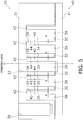
- FIG. 9 is a diagram showing values of the side clearance ⁇ in the scroll structure according to the present invention.
- FIG. 10 is a diagram showing a changed state of the side clearance ⁇ due to the thermal expansion during operation in the case of employing the scroll structure according to the present invention.
- the increase in the tooth thickness of each of the wraps 32 and 42 due to the thermal expansion becomes larger at the parts near the inner peripheries of the wraps 32 and 42 than that at the parts near the outer peripheries of the wraps 32 and 42 (see the side surfaces 34, 35, 44, and 45 of the wraps 32 and 42 as indicated by the broken lines in FIG. 2 and 3 ).
- the side clearance ⁇ between the side surface 34, 35 of the fixed-side wrap 32 and the side surface 44, 45 of the movable-side wrap 42 tends to be smaller at the parts near the inner peripheries of the wraps 32 and 42 (i.e., winding start parts of the wraps 32 and 42) than that at the parts near the outer peripheries of the wraps 32 and 42 (i.e., winding end parts of the wrap 32, 42 (see FIGS. 4 and 5 ).
- the side clearance ⁇ is formed between the side surface 34, 35 of the fixed-side wrap 32 and the side surface 44, 45 of the movable-side wrap 42 so as to increase from the outer peripheral side toward the inner peripheral side.
- FIG. 6 shows the shape of the scrolls in a state where the orbiting operation of the movable scroll 40 is not performed, that is, in a state where the thermal expansion of the scrolls 30 and 40 does not occur during the operation.
- this configuration can cancel the tendency for the side clearance ⁇ to become smaller at the parts near the inner peripheries of the wraps 32 and 42 than that at the parts near the outer peripheries of the wraps 32 and 42 due to the thermal expansion during the operation, so that the side clearance ⁇ at the part near the inner periphery of each of the wraps 32 and 42 is less likely to become extremely small, and that the side clearance ⁇ at the part near the outer periphery of the wraps 32 and 42 is less likely to become extremely large during the operation, thus making it possible to reduce the friction loss and leakage loss of the refrigerant.
- an increase in the side clearance ⁇ is set such that the side clearance ⁇ approaches a uniform state from the outer peripheral side to the inner peripheral side during the orbiting operation of the movable scroll 40 (during operation).
- the term "uniform state" as used herein means that the side clearance ⁇ formed when an operation of the orbiting the movable scroll 40 (during a non-operation) is not performed (see the side clearance ⁇ indicated by the solid line in FIG. 9 and the side clearances ⁇ 1 to ⁇ 4 in FIG.
- this configuration can cancel the tendency for the side clearance ⁇ to become smaller at the parts near the inner peripheries of the wraps 32 and 42 than that at the parts near the outer peripheries of the wraps 32 and 42 until the side clearance ⁇ becomes substantially uniform from the outer peripheral side to the inner peripheral side during the operation. Because of this, the side clearance ⁇ at the parts near the inner peripheries of the wraps 32 and 42 is less likely to become extremely small, and the side clearance ⁇ at the parts near the outer peripheries of the wraps 32 and 42 is less likely to become extremely large, thus making it possible to significantly reduce the friction loss and leakage loss of the refrigerant.
- the temperature of the wraps 32 and 42 during the compression process tends to drastically increase at the parts near the inner peripheries of theses wraps than at the parts near the outer peripheries of the wraps, i.e., the temperature increase rate becomes larger from the outer peripheral side to the inner peripheral side. Because of this, the contraction of the side clearance ⁇ due to the thermal expansion during the operation tends to become much more remarkable at the part near the inner periphery of the wraps 32 and 42 than at the part near the outer periphery of the wrap, i.e., a contracted range of the wrap becomes larger from the outer peripheral side to the inner peripheral side.
- an increase in the side clearance ⁇ is set so as to cancel this tendency, specifically, such that an increase rate of the side clearance becomes larger from the outer peripheral side to the inner peripheral side (see the side clearance ⁇ indicated by the solid line in FIG. 9 and the side clearances ⁇ 1 to ⁇ 4 indicated by the solid line in FIG. 6 ).
- the side clearance ⁇ is increased exponentially from the parts near the outer peripheries of the wraps 32 and 42 to the parts near the inner peripheries thereof (see the side clearance ⁇ indicated by the solid line in FIG. 9 ).
- the side clearance ⁇ can be appropriately set according to the tendency of the temperature increase during the compression process, so that the surface clearance ⁇ at the part near the inner periphery of each of the wraps 32 and 42 is less likely to become extremely small, and that the surface clearance ⁇ at the part near the outer periphery of each of the wraps 32 and 42 is less likely to become extremely large, thus making it possible to significantly reduce the friction loss and leakage loss of the refrigerant.
- the tooth thickness ts of the fixed-side wrap 32 is decreased in the order of ts1, ts2, ts3, and ts4 from the part near the outer periphery of the wrap 32 to the part near the inner periphery thereof, and concurrently, the tooth thickness tr of the movable-side wrap 42 is made smaller in the order of tr1, tr2, tr3, and tr4 from the part near the outer periphery of the wrap 42 to the part near the inner periphery thereof.
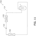
- the above-mentioned scroll compressor 1 is employed in an air conditioning apparatus 100 that includes a refrigerant circuit 101 shown in FIG. 11 .
- the refrigerant circuit 101 is configured by sequentially connecting the scroll compressor 1 for compressing a refrigerant, a radiator 102 for dissipating heat from the refrigerant, an expansion mechanism 103 for decompressing the refrigerant, and an evaporator 104 for evaporating the refrigerant.
- the refrigerant circuit 101 is filled with the refrigerant containing R32.
- the tooth thicknesses tr and ts of the wraps 32 and 42 of the scrolls 30 and 40 are more likely to increase due to the thermal expansion of the wraps.
- an increase in each of the tooth thicknesses tr and ts of the wraps 32 and 42 in the scrolls 30 and 40 due to the thermal expansion tends to become more remarkable at the parts near the inner peripheries of the wraps 32 and 42 than at the parts near the outer peripheries of the wraps.
- the scroll compressor 1 employs the scroll structure arranged in consideration of the thermal expansion of the scrolls 30 and 40 during operation, so that a side clearance ⁇ at the part near the inner periphery of each of the wraps 32 and 42 is less likely to become extremely small, and that a side clearance ⁇ at the part near the outer periphery of each of the wraps 32 and 42 is less likely to become extremely large during the operation.
- the friction loss and leakage loss of the refrigerant in the scroll compressor 1 can be reduced, which contributes to improvement of an air conditioning capability of the air conditioning apparatus 100.
- the increase in the side clearance ⁇ can be obtained by decreasing the tooth thicknesses ts and tr of the fixed-side wrap 32 and the movable-side wrap 42 from the outer peripheral side to the inner peripheral side in consideration of the thermal expansion of the scrolls 30 and 40 during the operation.
- the configuration of the scroll compressor is not limited thereto.
- the increase in the side clearance ⁇ may be obtained by decreasing only the tooth thickness ts of the fixed-side wrap 32 from the outer peripheral side to the inner peripheral side, or by decreasing only the tooth thickness tr of the movable-side wrap 42 from the outer peripheral side to the inner peripheral side.
- the present invention can be widely applied to scroll compressors and air conditioning apparatuses including the same.
Landscapes
- Engineering & Computer Science (AREA)
- Mechanical Engineering (AREA)
- General Engineering & Computer Science (AREA)
- Rotary Pumps (AREA)
- Compressor (AREA)
Claims (5)
- Spiralverdichter (1), umfassend:
eine feststehende Spirale (30) mit einer spiralförmigen, festseitigen Windung (32), die aufrecht auf einer Oberfläche einer festseitigen Platte (31) positioniert ist; und
eine bewegliche Spirale (40), die umlaufend angeordnet ist, um der feststehenden Spirale (30) gegenüber zu stehen, wobei die bewegliche Spirale eine spiralförmige, bewegungsseitige Windung(42) aufweist, die aufrecht auf einer Oberfläche einer bewegungsseitigen Platte (41) positioniert ist, wobei die bewegungsseitige Windung so konfiguriert ist, dass sie mit der festseitigen Windung (32) ineinandergreift, wobei
ein Seitenabstand (δ) zwischen einer Seitenfläche (34, 35) der festseitigen Windung (32) und einer Seitenfläche (44, 45) der bewegungsseitigen Windung (42) so ausgebildet ist, dass er von einer äußeren Umfangsseite zu einer inneren Umfangsseite jeder der Windungen hin zunimmt,
dadurch gekennzeichnet, dass die Zunahme des Seitenabstands (δ) so eingestellt ist, dass eine Zunahmerate des Seitenabstands von der äußeren Umfangsseite zu der inneren Umfangsseite hin größer wird. - Spiralverdichter (1) nach Anspruch 1, wobei die Zunahme des Seitenabstands (δ) so festgelegt ist, dass sich der Seitenabstand (δ) während eines Umlaufvorgangs der beweglichen Spirale (40) von der äußeren Umfangsseite zu der inneren Umfangsseite einem konstanten Zustand nähert.
- Spiralverdichter (1) nach einem der Ansprüche 1 bis 2, wobei
die Zunahme des Seitenabstands (δ) durch Verringerung einer Zahndicke der festseitigen Windung (32) und/oder der bewegungsseitigen Windung (42) von der äußeren Umfangsseite zu der inneren Umfangsseite erhalten wird. - Spiralverdichter (1) nach einem der Ansprüche 1 bis 3, der zum Verdichten eines R32 enthaltenden Kältemittels verwendet wird.
- Klimaanlage (100), umfassend
den Spiralverdichter (1) nach einem der Ansprüche 1 bis 4.
Applications Claiming Priority (2)
| Application Number | Priority Date | Filing Date | Title |
|---|---|---|---|
| JP2016012037A JP6226002B2 (ja) | 2016-01-26 | 2016-01-26 | スクロール圧縮機及びそれを備えた空気調和装置 |
| PCT/JP2017/002364 WO2017130971A1 (ja) | 2016-01-26 | 2017-01-24 | スクロール圧縮機及びそれを備えた空気調和装置 |
Publications (3)
| Publication Number | Publication Date |
|---|---|
| EP3409946A1 EP3409946A1 (de) | 2018-12-05 |
| EP3409946A4 EP3409946A4 (de) | 2019-01-23 |
| EP3409946B1 true EP3409946B1 (de) | 2020-03-11 |
Family
ID=59398344
Family Applications (1)
| Application Number | Title | Priority Date | Filing Date |
|---|---|---|---|
| EP17744201.9A Active EP3409946B1 (de) | 2016-01-26 | 2017-01-24 | Spiralverdichter und klimaanlage damit |
Country Status (6)
| Country | Link |
|---|---|
| US (1) | US10502209B2 (de) |
| EP (1) | EP3409946B1 (de) |
| JP (1) | JP6226002B2 (de) |
| CN (1) | CN108496008B (de) |
| ES (1) | ES2795662T3 (de) |
| WO (1) | WO2017130971A1 (de) |
Families Citing this family (5)
| Publication number | Priority date | Publication date | Assignee | Title |
|---|---|---|---|---|
| JP6810658B2 (ja) * | 2017-06-01 | 2021-01-06 | ダイキン工業株式会社 | スクロール圧縮機 |
| JP6409910B1 (ja) * | 2017-06-14 | 2018-10-24 | ダイキン工業株式会社 | スクロール圧縮機 |
| EP4047208B1 (de) * | 2019-10-15 | 2026-01-28 | Mitsubishi Electric Corporation | Spiralverdichter |
| CN117329123B (zh) * | 2023-10-18 | 2026-05-08 | 上海松芝酷恒新能源技术有限公司 | 涡旋式压缩机及涡旋齿型线的修正方法 |
| EP4538532A3 (de) * | 2025-02-25 | 2025-08-27 | Pfeiffer Vacuum Technology AG | Scrollvakuumpumpe |
Family Cites Families (15)
| Publication number | Priority date | Publication date | Assignee | Title |
|---|---|---|---|---|
| JPH0733828B2 (ja) * | 1986-12-29 | 1995-04-12 | 株式会社日立製作所 | スクロール形真空ポンプ |
| JP2677385B2 (ja) * | 1988-06-30 | 1997-11-17 | 株式会社日立製作所 | スクロール流体機械 |
| US5320505A (en) * | 1993-03-04 | 1994-06-14 | Tecumseh Products Company | Electrochemical machining of scroll wraps |
| JPH0791380A (ja) * | 1993-09-22 | 1995-04-04 | Mitsubishi Electric Corp | スクロール圧縮機 |
| JP3043979B2 (ja) * | 1995-10-20 | 2000-05-22 | サンデン株式会社 | スクロール型圧縮機用ボトムプレート |
| US6224357B1 (en) * | 1998-09-29 | 2001-05-01 | Tokioco Ltd. | Scroll fluid machine having an orbiting radius varying mechanism and a clearance between the wrap portions |
| JP3747358B2 (ja) * | 1999-06-23 | 2006-02-22 | 株式会社日立製作所 | スクロール形流体機械の製作方法 |
| US7080522B2 (en) * | 2000-01-04 | 2006-07-25 | Daikin Industries, Ltd. | Car air conditioner and car with its conditioner |
| ES2296662T3 (es) * | 2000-01-04 | 2008-05-01 | Daikin Industries, Ltd. | Acondicionador de aire para automovil y automovil equipado con este acondicionador. |
| CN1249348C (zh) * | 2000-11-22 | 2006-04-05 | 松下电器产业株式会社 | 涡旋压缩机 |
| KR100425740B1 (ko) * | 2002-02-09 | 2004-04-01 | 엘지전자 주식회사 | 스크롤 압축기의 마찰손실 저감장치 |
| JP2009174406A (ja) * | 2008-01-24 | 2009-08-06 | Panasonic Corp | スクロール圧縮機 |
| EP3301303B1 (de) * | 2010-01-22 | 2018-12-05 | Daikin Industries, Ltd. | Spiralverdichter |
| JP6125216B2 (ja) * | 2012-12-14 | 2017-05-10 | サンデンホールディングス株式会社 | スクロール型流体機械 |
| JP6081577B2 (ja) | 2013-03-29 | 2017-02-15 | ジョンソンコントロールズ ヒタチ エア コンディショニング テクノロジー(ホンコン)リミテッド | スクロール圧縮機 |
-
2016
- 2016-01-26 JP JP2016012037A patent/JP6226002B2/ja active Active
-
2017
- 2017-01-24 EP EP17744201.9A patent/EP3409946B1/de active Active
- 2017-01-24 WO PCT/JP2017/002364 patent/WO2017130971A1/ja not_active Ceased
- 2017-01-24 US US16/072,366 patent/US10502209B2/en active Active
- 2017-01-24 ES ES17744201T patent/ES2795662T3/es active Active
- 2017-01-24 CN CN201780008132.0A patent/CN108496008B/zh active Active
Non-Patent Citations (1)
| Title |
|---|
| None * |
Also Published As
| Publication number | Publication date |
|---|---|
| ES2795662T3 (es) | 2020-11-24 |
| WO2017130971A1 (ja) | 2017-08-03 |
| EP3409946A1 (de) | 2018-12-05 |
| CN108496008A (zh) | 2018-09-04 |
| US10502209B2 (en) | 2019-12-10 |
| EP3409946A4 (de) | 2019-01-23 |
| CN108496008B (zh) | 2021-08-24 |
| US20190032659A1 (en) | 2019-01-31 |
| JP2017133380A (ja) | 2017-08-03 |
| JP6226002B2 (ja) | 2017-11-08 |
Similar Documents
| Publication | Publication Date | Title |
|---|---|---|
| EP2690287B1 (de) | Spiralverdichter | |
| US10502209B2 (en) | Scroll compressor and air conditioning apparatus including the same | |
| EP2221481B1 (de) | Spiralverdichter | |
| JP3731069B2 (ja) | 圧縮機 | |
| JP4471034B2 (ja) | スクロール圧縮機 | |
| JP4519489B2 (ja) | スクロール圧縮機 | |
| EP2497954B1 (de) | Spiralverdichter | |
| US9879679B2 (en) | Scroll compressor | |
| JP2018048649A (ja) | スクロール圧縮機 | |
| US20250172142A1 (en) | Scroll compressor and refrigerating apparatus | |
| EP4102074A1 (de) | Spiralverdichter | |
| JP2017186948A (ja) | スクロール圧縮機及びそれを備えた空気調和装置 | |
| US12385486B2 (en) | Scroll compressor and refrigeration device | |
| JP7702647B2 (ja) | スクロール圧縮機 | |
| JP2016156297A (ja) | スクロール圧縮機 | |
| CN109416042B (zh) | 涡旋式压缩机 | |
| CN113316687B (zh) | 涡旋式压缩机 | |
| JP2010121577A (ja) | スクロール圧縮機 | |
| EP4047208B1 (de) | Spiralverdichter | |
| US10851779B2 (en) | Scroll compressor having gap between tip spiral scroll wrap to end plate of fixed and orbiting scrolls that differs in axial length from gap between support of oldham ring and end plate of orbiting scroll | |
| JP2017133445A (ja) | スクロール圧縮機及びそれを備えた空気調和装置 | |
| JP5229129B2 (ja) | スクロール圧縮機 | |
| JP2006070711A (ja) | スクロール圧縮機 | |
| JP2007023957A (ja) | スクロール圧縮機 | |
| JP2020033894A (ja) | 密閉型電動圧縮機 |
Legal Events
| Date | Code | Title | Description |
|---|---|---|---|
| STAA | Information on the status of an ep patent application or granted ep patent |
Free format text: STATUS: THE INTERNATIONAL PUBLICATION HAS BEEN MADE |
|
| PUAI | Public reference made under article 153(3) epc to a published international application that has entered the european phase |
Free format text: ORIGINAL CODE: 0009012 |
|
| STAA | Information on the status of an ep patent application or granted ep patent |
Free format text: STATUS: REQUEST FOR EXAMINATION WAS MADE |
|
| 17P | Request for examination filed |
Effective date: 20180814 |
|
| AK | Designated contracting states |
Kind code of ref document: A1 Designated state(s): AL AT BE BG CH CY CZ DE DK EE ES FI FR GB GR HR HU IE IS IT LI LT LU LV MC MK MT NL NO PL PT RO RS SE SI SK SM TR |
|
| AX | Request for extension of the european patent |
Extension state: BA ME |
|
| A4 | Supplementary search report drawn up and despatched |
Effective date: 20181220 |
|
| RIC1 | Information provided on ipc code assigned before grant |
Ipc: F04C 23/00 20060101ALN20181214BHEP Ipc: F04C 18/02 20060101AFI20181214BHEP |
|
| DAV | Request for validation of the european patent (deleted) | ||
| DAX | Request for extension of the european patent (deleted) | ||
| STAA | Information on the status of an ep patent application or granted ep patent |
Free format text: STATUS: EXAMINATION IS IN PROGRESS |
|
| 17Q | First examination report despatched |
Effective date: 20190711 |
|
| GRAP | Despatch of communication of intention to grant a patent |
Free format text: ORIGINAL CODE: EPIDOSNIGR1 |
|
| STAA | Information on the status of an ep patent application or granted ep patent |
Free format text: STATUS: GRANT OF PATENT IS INTENDED |
|
| RIC1 | Information provided on ipc code assigned before grant |
Ipc: F04C 18/02 20060101AFI20191119BHEP Ipc: F04C 23/00 20060101ALN20191119BHEP |
|
| INTG | Intention to grant announced |
Effective date: 20191209 |
|
| GRAS | Grant fee paid |
Free format text: ORIGINAL CODE: EPIDOSNIGR3 |
|
| GRAA | (expected) grant |
Free format text: ORIGINAL CODE: 0009210 |
|
| STAA | Information on the status of an ep patent application or granted ep patent |
Free format text: STATUS: THE PATENT HAS BEEN GRANTED |
|
| AK | Designated contracting states |
Kind code of ref document: B1 Designated state(s): AL AT BE BG CH CY CZ DE DK EE ES FI FR GB GR HR HU IE IS IT LI LT LU LV MC MK MT NL NO PL PT RO RS SE SI SK SM TR |
|
| REG | Reference to a national code |
Ref country code: GB Ref legal event code: FG4D |
|
| REG | Reference to a national code |
Ref country code: CH Ref legal event code: EP |
|
| REG | Reference to a national code |
Ref country code: AT Ref legal event code: REF Ref document number: 1243449 Country of ref document: AT Kind code of ref document: T Effective date: 20200315 |
|
| REG | Reference to a national code |
Ref country code: DE Ref legal event code: R096 Ref document number: 602017013043 Country of ref document: DE |
|
| REG | Reference to a national code |
Ref country code: IE Ref legal event code: FG4D |
|
| PG25 | Lapsed in a contracting state [announced via postgrant information from national office to epo] |
Ref country code: FI Free format text: LAPSE BECAUSE OF FAILURE TO SUBMIT A TRANSLATION OF THE DESCRIPTION OR TO PAY THE FEE WITHIN THE PRESCRIBED TIME-LIMIT Effective date: 20200311 Ref country code: RS Free format text: LAPSE BECAUSE OF FAILURE TO SUBMIT A TRANSLATION OF THE DESCRIPTION OR TO PAY THE FEE WITHIN THE PRESCRIBED TIME-LIMIT Effective date: 20200311 Ref country code: NO Free format text: LAPSE BECAUSE OF FAILURE TO SUBMIT A TRANSLATION OF THE DESCRIPTION OR TO PAY THE FEE WITHIN THE PRESCRIBED TIME-LIMIT Effective date: 20200611 |
|
| REG | Reference to a national code |
Ref country code: NL Ref legal event code: MP Effective date: 20200311 |
|
| PG25 | Lapsed in a contracting state [announced via postgrant information from national office to epo] |
Ref country code: HR Free format text: LAPSE BECAUSE OF FAILURE TO SUBMIT A TRANSLATION OF THE DESCRIPTION OR TO PAY THE FEE WITHIN THE PRESCRIBED TIME-LIMIT Effective date: 20200311 Ref country code: LV Free format text: LAPSE BECAUSE OF FAILURE TO SUBMIT A TRANSLATION OF THE DESCRIPTION OR TO PAY THE FEE WITHIN THE PRESCRIBED TIME-LIMIT Effective date: 20200311 Ref country code: SE Free format text: LAPSE BECAUSE OF FAILURE TO SUBMIT A TRANSLATION OF THE DESCRIPTION OR TO PAY THE FEE WITHIN THE PRESCRIBED TIME-LIMIT Effective date: 20200311 Ref country code: GR Free format text: LAPSE BECAUSE OF FAILURE TO SUBMIT A TRANSLATION OF THE DESCRIPTION OR TO PAY THE FEE WITHIN THE PRESCRIBED TIME-LIMIT Effective date: 20200612 Ref country code: BG Free format text: LAPSE BECAUSE OF FAILURE TO SUBMIT A TRANSLATION OF THE DESCRIPTION OR TO PAY THE FEE WITHIN THE PRESCRIBED TIME-LIMIT Effective date: 20200611 |
|
| REG | Reference to a national code |
Ref country code: LT Ref legal event code: MG4D |
|
| PG25 | Lapsed in a contracting state [announced via postgrant information from national office to epo] |
Ref country code: NL Free format text: LAPSE BECAUSE OF FAILURE TO SUBMIT A TRANSLATION OF THE DESCRIPTION OR TO PAY THE FEE WITHIN THE PRESCRIBED TIME-LIMIT Effective date: 20200311 |
|
| PG25 | Lapsed in a contracting state [announced via postgrant information from national office to epo] |
Ref country code: SM Free format text: LAPSE BECAUSE OF FAILURE TO SUBMIT A TRANSLATION OF THE DESCRIPTION OR TO PAY THE FEE WITHIN THE PRESCRIBED TIME-LIMIT Effective date: 20200311 Ref country code: RO Free format text: LAPSE BECAUSE OF FAILURE TO SUBMIT A TRANSLATION OF THE DESCRIPTION OR TO PAY THE FEE WITHIN THE PRESCRIBED TIME-LIMIT Effective date: 20200311 Ref country code: CZ Free format text: LAPSE BECAUSE OF FAILURE TO SUBMIT A TRANSLATION OF THE DESCRIPTION OR TO PAY THE FEE WITHIN THE PRESCRIBED TIME-LIMIT Effective date: 20200311 Ref country code: EE Free format text: LAPSE BECAUSE OF FAILURE TO SUBMIT A TRANSLATION OF THE DESCRIPTION OR TO PAY THE FEE WITHIN THE PRESCRIBED TIME-LIMIT Effective date: 20200311 Ref country code: LT Free format text: LAPSE BECAUSE OF FAILURE TO SUBMIT A TRANSLATION OF THE DESCRIPTION OR TO PAY THE FEE WITHIN THE PRESCRIBED TIME-LIMIT Effective date: 20200311 Ref country code: SK Free format text: LAPSE BECAUSE OF FAILURE TO SUBMIT A TRANSLATION OF THE DESCRIPTION OR TO PAY THE FEE WITHIN THE PRESCRIBED TIME-LIMIT Effective date: 20200311 Ref country code: PT Free format text: LAPSE BECAUSE OF FAILURE TO SUBMIT A TRANSLATION OF THE DESCRIPTION OR TO PAY THE FEE WITHIN THE PRESCRIBED TIME-LIMIT Effective date: 20200805 Ref country code: IS Free format text: LAPSE BECAUSE OF FAILURE TO SUBMIT A TRANSLATION OF THE DESCRIPTION OR TO PAY THE FEE WITHIN THE PRESCRIBED TIME-LIMIT Effective date: 20200711 |
|
| REG | Reference to a national code |
Ref country code: AT Ref legal event code: MK05 Ref document number: 1243449 Country of ref document: AT Kind code of ref document: T Effective date: 20200311 |
|
| REG | Reference to a national code |
Ref country code: ES Ref legal event code: FG2A Ref document number: 2795662 Country of ref document: ES Kind code of ref document: T3 Effective date: 20201124 |
|
| REG | Reference to a national code |
Ref country code: DE Ref legal event code: R097 Ref document number: 602017013043 Country of ref document: DE |
|
| PLBE | No opposition filed within time limit |
Free format text: ORIGINAL CODE: 0009261 |
|
| STAA | Information on the status of an ep patent application or granted ep patent |
Free format text: STATUS: NO OPPOSITION FILED WITHIN TIME LIMIT |
|
| PG25 | Lapsed in a contracting state [announced via postgrant information from national office to epo] |
Ref country code: AT Free format text: LAPSE BECAUSE OF FAILURE TO SUBMIT A TRANSLATION OF THE DESCRIPTION OR TO PAY THE FEE WITHIN THE PRESCRIBED TIME-LIMIT Effective date: 20200311 Ref country code: DK Free format text: LAPSE BECAUSE OF FAILURE TO SUBMIT A TRANSLATION OF THE DESCRIPTION OR TO PAY THE FEE WITHIN THE PRESCRIBED TIME-LIMIT Effective date: 20200311 |
|
| 26N | No opposition filed |
Effective date: 20201214 |
|
| PG25 | Lapsed in a contracting state [announced via postgrant information from national office to epo] |
Ref country code: SI Free format text: LAPSE BECAUSE OF FAILURE TO SUBMIT A TRANSLATION OF THE DESCRIPTION OR TO PAY THE FEE WITHIN THE PRESCRIBED TIME-LIMIT Effective date: 20200311 Ref country code: PL Free format text: LAPSE BECAUSE OF FAILURE TO SUBMIT A TRANSLATION OF THE DESCRIPTION OR TO PAY THE FEE WITHIN THE PRESCRIBED TIME-LIMIT Effective date: 20200311 |
|
| PG25 | Lapsed in a contracting state [announced via postgrant information from national office to epo] |
Ref country code: MC Free format text: LAPSE BECAUSE OF FAILURE TO SUBMIT A TRANSLATION OF THE DESCRIPTION OR TO PAY THE FEE WITHIN THE PRESCRIBED TIME-LIMIT Effective date: 20200311 |
|
| REG | Reference to a national code |
Ref country code: CH Ref legal event code: PL |
|
| PG25 | Lapsed in a contracting state [announced via postgrant information from national office to epo] |
Ref country code: LU Free format text: LAPSE BECAUSE OF NON-PAYMENT OF DUE FEES Effective date: 20210124 |
|
| REG | Reference to a national code |
Ref country code: BE Ref legal event code: MM Effective date: 20210131 |
|
| PG25 | Lapsed in a contracting state [announced via postgrant information from national office to epo] |
Ref country code: LI Free format text: LAPSE BECAUSE OF NON-PAYMENT OF DUE FEES Effective date: 20210131 Ref country code: CH Free format text: LAPSE BECAUSE OF NON-PAYMENT OF DUE FEES Effective date: 20210131 |
|
| PG25 | Lapsed in a contracting state [announced via postgrant information from national office to epo] |
Ref country code: IE Free format text: LAPSE BECAUSE OF NON-PAYMENT OF DUE FEES Effective date: 20210124 |
|
| PG25 | Lapsed in a contracting state [announced via postgrant information from national office to epo] |
Ref country code: BE Free format text: LAPSE BECAUSE OF NON-PAYMENT OF DUE FEES Effective date: 20210131 |
|
| PG25 | Lapsed in a contracting state [announced via postgrant information from national office to epo] |
Ref country code: CY Free format text: LAPSE BECAUSE OF FAILURE TO SUBMIT A TRANSLATION OF THE DESCRIPTION OR TO PAY THE FEE WITHIN THE PRESCRIBED TIME-LIMIT Effective date: 20200311 |
|
| P01 | Opt-out of the competence of the unified patent court (upc) registered |
Effective date: 20230525 |
|
| PG25 | Lapsed in a contracting state [announced via postgrant information from national office to epo] |
Ref country code: HU Free format text: LAPSE BECAUSE OF FAILURE TO SUBMIT A TRANSLATION OF THE DESCRIPTION OR TO PAY THE FEE WITHIN THE PRESCRIBED TIME-LIMIT; INVALID AB INITIO Effective date: 20170124 |
|
| PG25 | Lapsed in a contracting state [announced via postgrant information from national office to epo] |
Ref country code: MK Free format text: LAPSE BECAUSE OF FAILURE TO SUBMIT A TRANSLATION OF THE DESCRIPTION OR TO PAY THE FEE WITHIN THE PRESCRIBED TIME-LIMIT Effective date: 20200311 |
|
| PG25 | Lapsed in a contracting state [announced via postgrant information from national office to epo] |
Ref country code: TR Free format text: LAPSE BECAUSE OF FAILURE TO SUBMIT A TRANSLATION OF THE DESCRIPTION OR TO PAY THE FEE WITHIN THE PRESCRIBED TIME-LIMIT Effective date: 20200311 |
|
| PG25 | Lapsed in a contracting state [announced via postgrant information from national office to epo] |
Ref country code: MT Free format text: LAPSE BECAUSE OF FAILURE TO SUBMIT A TRANSLATION OF THE DESCRIPTION OR TO PAY THE FEE WITHIN THE PRESCRIBED TIME-LIMIT Effective date: 20200311 |
|
| PGFP | Annual fee paid to national office [announced via postgrant information from national office to epo] |
Ref country code: GB Payment date: 20251204 Year of fee payment: 10 |
|
| PGFP | Annual fee paid to national office [announced via postgrant information from national office to epo] |
Ref country code: FR Payment date: 20251128 Year of fee payment: 10 |
|
| PGFP | Annual fee paid to national office [announced via postgrant information from national office to epo] |
Ref country code: ES Payment date: 20260203 Year of fee payment: 10 |
|
| PGFP | Annual fee paid to national office [announced via postgrant information from national office to epo] |
Ref country code: DE Payment date: 20251203 Year of fee payment: 10 |
|
| PGFP | Annual fee paid to national office [announced via postgrant information from national office to epo] |
Ref country code: IT Payment date: 20251219 Year of fee payment: 10 |