EP3407934B1 - Spritzenhalterung mit hexagonalen röhren und verschiebung der mittelpunkte - Google Patents
Spritzenhalterung mit hexagonalen röhren und verschiebung der mittelpunkte Download PDFInfo
- Publication number
- EP3407934B1 EP3407934B1 EP17704892.3A EP17704892A EP3407934B1 EP 3407934 B1 EP3407934 B1 EP 3407934B1 EP 17704892 A EP17704892 A EP 17704892A EP 3407934 B1 EP3407934 B1 EP 3407934B1
- Authority
- EP
- European Patent Office
- Prior art keywords
- syringe
- chimney
- nest
- nesting
- syringe nest
- Prior art date
- Legal status (The legal status is an assumption and is not a legal conclusion. Google has not performed a legal analysis and makes no representation as to the accuracy of the status listed.)
- Active
Links
Images


Classifications
-
- A—HUMAN NECESSITIES
- A61—MEDICAL OR VETERINARY SCIENCE; HYGIENE
- A61M—DEVICES FOR INTRODUCING MEDIA INTO, OR ONTO, THE BODY; DEVICES FOR TRANSDUCING BODY MEDIA OR FOR TAKING MEDIA FROM THE BODY; DEVICES FOR PRODUCING OR ENDING SLEEP OR STUPOR
- A61M5/00—Devices for bringing media into the body in a subcutaneous, intra-vascular or intramuscular way; Accessories therefor, e.g. filling or cleaning devices, arm-rests
- A61M5/008—Racks for supporting syringes or needles
-
- A—HUMAN NECESSITIES
- A61—MEDICAL OR VETERINARY SCIENCE; HYGIENE
- A61M—DEVICES FOR INTRODUCING MEDIA INTO, OR ONTO, THE BODY; DEVICES FOR TRANSDUCING BODY MEDIA OR FOR TAKING MEDIA FROM THE BODY; DEVICES FOR PRODUCING OR ENDING SLEEP OR STUPOR
- A61M2207/00—Methods of manufacture, assembly or production
- A61M2207/10—Device therefor
-
- B—PERFORMING OPERATIONS; TRANSPORTING
- B32—LAYERED PRODUCTS
- B32B—LAYERED PRODUCTS, i.e. PRODUCTS BUILT-UP OF STRATA OF FLAT OR NON-FLAT, e.g. CELLULAR OR HONEYCOMB, FORM
- B32B3/00—Layered products comprising a layer with external or internal discontinuities or unevennesses, or a layer of non-planar shape; Layered products comprising a layer having particular features of form
- B32B3/10—Layered products comprising a layer with external or internal discontinuities or unevennesses, or a layer of non-planar shape; Layered products comprising a layer having particular features of form characterised by a discontinuous layer, i.e. formed of separate pieces of material
- B32B3/12—Layered products comprising a layer with external or internal discontinuities or unevennesses, or a layer of non-planar shape; Layered products comprising a layer having particular features of form characterised by a discontinuous layer, i.e. formed of separate pieces of material characterised by a layer of regularly- arranged cells, e.g. a honeycomb structure
Definitions
- the present invention relates to a syringe nest.
- the present invention relates to a syringe nest of such a geometry that a plurality of syringes may be securely individually nested in chimneys in close proximity to each other, without compromising injection mold tool integrity.
- a syringe nest is typically a substantially planar tray which sits in a syringe tub and has a plurality of individual nesting units, typically referred to as chimneys, each capable of receiving a syringe, to contain, transport and fill syringes in various manufacturing processes.
- the syringe nest is typically used in automation processes for the assembly of, for example, pre-filled syringes.
- the chimneys of a syringe nest have a defined center to center distance that must remain accurate, in order to ensure that the nest is compatible with existing manufacturing, packaging, and filling equipment.
- the quantity sizes of syringe nests have been increasing in recent years, with 160 chimneys/nest potentially becoming the new standard.
- the present invention relates to a syringe nest having a hexagonal structure that enables more robust mold geometry, but which also preserves manufacturer-specified center to center distance of nest chimneys and syringes, such that the nest is acceptable for use in existing automation and filling equipment.
- the present invention also relates to a syringe nest which reduces or eliminates the troublesome and unpredictable warping condition that syringe nests may exhibit post sterilization procedures (e.g., by gamma irradiation, ethylene oxide, autoclaving, etc.).
- the present invention relates to a syringe nest according to annexed independent claim 1.
- Other advantageous features are defined in the annexed dependent claims.
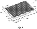
- the syringe nest includes a plurality of single nesting units, referred to herein as chimneys, 12.
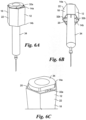
- the nest 10 can include a syringe 34 (e.g., see Figs. 6A-6C ) received within each of the plurality of chimneys 12.
- the nest 10 is generally configured as a planar tray. While the present embodiment is configured with the nest 10 configured as a planar square tray, the nest 10 can alternatively be configured into any planar fashion suitable for its intended use, such as a planar circular, rectangular, oval, or octagonal shaped tray.
- the nest includes a base 16 having a first surface 16a and an opposing second surface 16b.
- Each chimney 12 includes a generally hollow body 14 that extends distally from the first surface 16a of the base 16.
- the hollow body 14 includes a first open end 14a distal from the base 16 and a second open end 14b proximate the base 16.
- the hollow body 14 also includes a generally smooth interior wall surface 20 and an exterior wall surface 22.
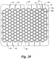
- each of the chimneys 12 preferably has a hexagonal shape or geometry.
- each chimney 12 has six sidewalls 18 and six connecting lines (also known as vertices or corners) 24.
- the hexagonal chimneys 12 are aligned symmetrically in a point to point, vertex to vertex, or corner to corner orientation. That is, the chimneys 12 are interconnected in such a manner that each line/vertex/corner 24 of one chimney 12 also forms the line/vertex/corner 24 of another chimney 12.
- Each chimney 12 thus shares at least one line/vertex/corner 24 with at least one other chimney 12. More preferably, except for the perimeter chimneys 12, every line/vertex/corner 24 of each chimney 12 is common to that of another chimney 12.
- each chimney 12 shares a common line/vertex/corner 24 with two or more other chimneys 12.
- Hexagonal chimneys 12 arranged in the line to line orientation naturally also form contiguous walls 26 that are advantageous for injection molding.
- Circular chimneys as shown in the prior art nest of Fig. 15 , would not allow for contiguous walls to be made without creating geometry that is disadvantageous to injection molding, namely a thin walled tool geometry.
- the geometry of the nest 10 according to the first preferred embodiment allows for maintaining a predetermined center to center distance D (e.g., as required by manufacturers), that is a predetermined distance D between a center C of one chimney 12 and a center C of an adjacent chimney 12, without excessive sidewall 18 thickness.
- an intermediate wall 28 is provided between the first and second open ends 30a, 30b of each of the triangular voids 30 (best seen in Fig. 3 ).
- the intermediately wall 28 preferably has a shape that conforms with the geometric shape of the void 30 (e.g., a triangular shaped intermediate wall 28).
- the intermediate wall 28 is horizontally-oriented (i.e., perpendicular to the direction in which the body 14 of each chimney 12 extends). Such walls 28 allow for more shallow injection molding draws and increase mold robustness.
- the plurality of hexagonal chimneys 12 are arranged in a honeycomb pattern, in order to maintain the predetermined center to center distance D of the chimneys 12, and more particularly the predetermined center to center distance D between the syringes to be placed within each chimney 12 ( Figs. 4A-6C ). That is, the chimneys 12 are interconnected in such a manner that at least one sidewall 18, and preferably each sidewall 18, of one chimney 12 also forms a sidewall 18 of another chimney 12 (i.e., contiguous walls), such that no triangular or other voids are formed between adjacent chimneys 12. Each chimney 12 thus shares at least one sidewall 18 with at least one other chimney 12. More preferably, with the exception of the outer peripheral chimneys 12, every sidewall 18 of each chimney 12 is common to that of another chimney 12. Thus, each chimney 12 shares a common sidewall 18 with a plurality of other chimneys 12.
- each of the hexagonal chimneys 12 has a relatively large diameter that enables maintaining the predetermined center to center distance D, but also does not have an excessive sidewall 18 thickness. Accordingly, the diameter D C of each chimney 12 is generally larger than the diameter of the flange of the syringe 34. As such, the syringe flange cannot rest on the chimney sidewalls 18.
- the entirety of the body 14 of each chimney 12 is positioned on one side of the planar base 16, namely on the first surface 16a of the base 16.
- a first portion of the body 14 extends distally from the first surface 16a of the base 16 and a second portion of the body 14 extends proximally from the second surface 16b of the base 16.
- the base 16 is positioned at an intermediate point between the first open end 14a and the second open end 14b of each hollow body 14.
- the base 16 is positioned at a geometric center point between the first and second ends 14a, 14b, but it will be understood that the base 16 may be located at any position between the two ends 14a, 14b.
- the base 16 essentially serves as a peripheral flange that extends in a midline plane of the plurality of chimneys 12, and which provides strength and stiffness to the nest 10 to reduce warping effects which occur during molding (e.g., by facilitating consistent cooling), post molding (e.g., by facilitating more uniform shrinkage), and sterilization (e.g., by providing a robust geometry that is more resistant to sterilization temperatures).
- the peripheral flange 16 also further enhances moldability and reduces injection molding cycle time, allowing for more shallow draws and increased mold robustness.
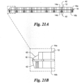
- the nest 10 further includes a plurality of reinforcing members or stiffening members 42.
- a plurality of stiffening members 42 are provided on the first surface 16a and on the second surface 16b of the base 16. More preferably, the stiffening member 42 are provided on the perimeter of the first and second surfaces 16a, 16b of the base 16 surrounding the plurality of chimneys 12.
- the stiffening members 42 are elongated stiffening ribs 42, each of which has a first end 42a proximate a chimney 12 and an opposing second end 42b proximate an edge of the base 16.
- each stiffening rib 42 extends at an angle from the peripheral edge of the base 12 toward the chimneys 12 to provide stiffness and strength to the base 12.
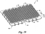
- an arcuate shaped edge ridge 44 also extends generally perpendicularly from the planar base 16 and defines an edge hole 46 (see, e.g., Figs. 1A-3 and 19-20 ).
- portions of the planar base 16 are merely recessed or indented to form the edge holes 46 (see, e.g,. Figs. 4A-5 ).
- One or more edge holes 46 are preferably included in the base 16 such that a user is able to insert a finger or tool through the edge holes 46 for ease of gripping.
- the edge rib 44 (if present) provides stiffness and strength for the base 16 proximate the edge holes 46.
- the edge holes 46 and edge rib 44 are not limited to inclusion in the edge of the base 16 and may be instead positioned at nearly any location on the base 16.
- each syringe 34 includes at least one retention member 32, and more preferably a plurality of retention members 32 (see Figs. 4 and 6C ).
- Each retention member 32 is preferably a radially inwardly extending member.
- each retention member 32 may be configured as a longitudinally extending rib formed on the interior wall surface 20 of each chimney 12.
- the retention members 32 may alternatively be configured as an annular rib, a flange, a flange-like rib, bumps, walls, shelves, pegs or the like extending from one or more of the internal surface 20 of the hexagonal chimney 12 sidewalls 18 proximate the first distal end 14a.
- each retention member 32 is in the form of a longitudinally extending rib that extends from the first distal end 14a of each chimney 12 toward the second proximal end 14b.
- Each rib 32 thus has a first end 32a proximate the first distal end 14a of each chimney 12 and a second end 32b proximate the second proximal end 14b of each chimney 12.
- the syringe 34 flange rests on the exposed surface (i.e., the first end 32a) of the one or more retention members 32 above the plane of the first distal end 14a of each chimney 12, as shown in Figs. 6A and 6C .
- each rib 32 extends along an entire height or length of each chimney 12 (i.e., from the first distal end 14a to the second proximal end 14b), but it will be understood that each rib 32 need not extend all the way to the second proximal end 14b.
- one or more ribs 32, and more preferably each rib 32 may be chamfered (preferably at the first end 32a), to assist in centering the syringe 34 within a respective chimney 12 and keeping the syringe 34 flange contained therein.
- Such a configuration may also prevent catching a safety system (not shown) on the chamfered ribs 32 during insertion of a syringe 34 into a chimney 12.
- each retention member 32 is in the form of a longitudinally extending rib that does not extend to the first distal end 14a of each chimney 12 (i.e., the open top of the chimney 12). That is, each rib 32 extends from the second proximal end 14b toward the first distal end 14a, but terminates before reaching the first distal end 14a. The first end 32a of the rib 32 is thus below the plane of the first distal end 14a. As such, in use, the syringe 34 flange rests on the exposed surface (i.e., the first end 32a) of the one or more retention members 32 below the plane of the first distal end 14a of each chimney 12.
- each retention member 32 is in the form of an annular shelf or shoulder extending inwardly from the interior surface 20 of the chimney 12 body 14 proximate the first distal end 14a. More particularly, the shelf 32 is formed below the plane of the first distal end 14a, such that, in use, the syringe 34 flange rests on the exposed surface of the shelf 32 below the plane of the first distal end 14a of each chimney 12.
- the shelf 32 may extend around only a portion of the interior periphery of the body 14, but preferably extends around the entire interior periphery thereof.
- cut-outs, ramps, or a cam geometry is implemented at the first distal end 14a (i.e., the top) of each chimney 12.
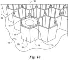
- the first open end 14a of each chimney 12 includes at least one cam 36a and at least one associated recess 36b, such that a syringe flange 34a contacts and travels over the at least one cam 36a and subsequently comes to rest in the at least one associated recess 36b.
- a first plurality of the sidewalls 18 is provided as a rounded cam 36a, while a second plurality of the sidewalls 18 is provided with a cut-out 36b.
- Such a geometry allows a syringe flange 34a to initially contact and pass or travel over the cams 36a and then rest on the cut-outs 36b, such that the syringe flange 34a falls or cams into a centered position within a respective chimney 12 via gravity, mechanical assist (e.g., vibration), tilting, or any other similar movement, as shown in the progression depicted in Figs. 9A-9D .
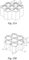
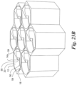
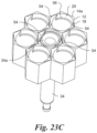
- FIG. 22A-22B and 23A-23E Two additional variations of cam geometries are shown in Figs. 22A-22B and 23A-23E , respectively.
- the cams 50, 54 of the variation of Figs. 22A-22B and 23A-23E function in a manner similar to the cams 36a of Figs. 9A-9D .
- the cams 50, 54 are still formed at the first distal end 14a of each chimney 12, but are formed within the interior of the hexagonal chimney walls 18. This is beneficial because the overall geometry of the chimney 12 is more compact and will not interfere with a Tyvek seal, filling, etc.
- first and second opposing and symmetrical pyramidal-shaped cams 50 are provided on the interior surface 20 of each chimney 12 at the first distal end 14a thereof.
- first and second opposing and symmetrical pyramidal-shaped cams 50 are provided on the interior surface 20 of each chimney 12 at the first distal end 14a thereof.
- the syringe flange 34a falls or cams into the centered position within a respective chimney 12 via gravity, mechanical assist (e.g., vibration), tilting, or any other movement that facilitates dropping of the flange 34a into the recess 52.
- the symmetrical cam design enables the possibility for the syringe 34 to balance across the top and/or edges of the opposing cams 50.
- first and second asymmetric cams 54 are provided.
- the cams 54 are in the form of opposing inclined surfaces, upon which the syringe flange 34a may slide and/or rotate to travel down into a recess 56. Similar to the embodiment of Figs. 9A-9D , , the syringe flange 34a falls or cams into the centered position within a respective chimney 12 via gravity, mechanical assist (e.g., vibration), tilting, or any other movement that facilitates dropping of the flange 34a into the recess 56.
- mechanical assist e.g., vibration
- the asymmetrical cam design makes a more effective use of gravity, as the syringe flange 34a will always fall on an incline (i.e., the inclined cams 54) or into the recess 56.
- the asymmetrical cam design also includes a vertical drop 58 into the flange recess 56 that is below the bottom cam 54. The vertical drop 58 will prevent the syringe 34 from rotating back up the cams 54 (e.g., during transportation, filling, etc.) and moving out of tolerance of the necessary center-to-center distance D. It will be understood that such a vertical drop may also be included in the symmetrical cam design of Figs. 22A-22B .
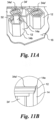
- the present invention is directed to a syringe 34' having a flange 34a' of a shape and size that conforms with the shape of the chimney 12. That is, the flange 34a' has a generally hexagonal geometry or shape.
- the interior periphery of the body 14 of the chimney 12 at its first end 14a is sized and contoured such that the syringe flange 34a' is pressure fit within the chimney 12, as shown in Fig. 11B .
- the chimney 12 may include one or more snap beads, ledges, bumps, ribs and the like to facilitate centering and capturing of the syringe flange 34a' within the chimney 12.
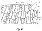
- each chimney 12 includes one or more chamfers 38 on the interior wall surface 20 to prevent catching on the chimney 12 during removal, as shown in Fig. 12 .
- Figs. 13A-13D show various other examples of the chimney 12 geometry.
- the chimneys 12 no longer have a hexagonal geometry, but are still arranged in a honeycomb pattern, so as to provide a surface on which the syringe 34 flange may rest, to maintain the predetermined center to center distance D, and to minimize sidewall thickness.
- Fig. 14 shows another example not being part of the invention, in which the hexagonal chimneys 12 are arranged in a spaced-apart manner, such that the sidewalls 18 are not contiguous and a void or gap 19 surrounds each chimney 12. That is, aside from the chimneys 12 located on the outer periphery of the nest 10, a uniform gap 19 fully surrounds each chimney 12. The uniform gaps 19 between each chimney 12 result in uniform cooling of the mold. In contrast, the gaps between circular chimneys, as in the prior art nest of Fig. 15 , would create varying thicknesses that are disadvantageous to mold heating and cooling.
- the body 14 of each chimney 12 includes a plurality of longitudinally extending slits 48 which separate the body 14 into a plurality of spaced apart portions.
- One or more of the portions of the body 14 may be formed as flexing members 40 for improved securing and centering of the syringe 34 barrel and flange within a respective chimney 12. Centering and securing the syringes 34 in the chimneys 12 enables consistent filling and minimal movement of the syringes 34 during transit and/or shipping.
- the flexing members 40 may have a geometry, such as being angled, tapered or ramped from one end 14a, 14b of the body 14 of the chimney 12 toward the other end 14a, 14b, so as to allow for easy flexing of the members 40 and, in turn, easy insertion and removal of a syringe 34.
- flexing members is not limited to a chimney 12 of a hexagonal geometry, but instead may be utilized on a chimney of various geometries, such as, for example, circular, square, triangular, and the like.
- a chimney 12 may have only one flexing member 40 that provides support to a syringe 34 to be inserted therein from one direction, thereby intentionally off-centering the syringe 34 barrel within the chimney 12.
- the chimney 12 pattern is similarly offset from center, such that once the syringes 34 are fully inserted within the chimneys 12, the syringes 34 are centered and aligned within the chimneys 12 for the filling position.
Landscapes
- Health & Medical Sciences (AREA)
- Vascular Medicine (AREA)
- Engineering & Computer Science (AREA)
- Anesthesiology (AREA)
- Biomedical Technology (AREA)
- Heart & Thoracic Surgery (AREA)
- Hematology (AREA)
- Life Sciences & Earth Sciences (AREA)
- Animal Behavior & Ethology (AREA)
- General Health & Medical Sciences (AREA)
- Public Health (AREA)
- Veterinary Medicine (AREA)
- Infusion, Injection, And Reservoir Apparatuses (AREA)
Claims (14)
- Spritzennest (10) umfassend:eine planare Basis (16) umfassend eine erste Fläche (16a) und eine entgegengesetzte zweite Fläche (16b), wobei die planare Basis (16) eine Vielzahl von Versteifungsgliedern (42) umfasst, die sich von zumindest einem Umfangsrand der planaren Basis (16) zu der Vielzahl von Einnisteinheiten (12) hin erstrecken; undeine Vielzahl von Einnisteinheiten (12), die sich von der planaren Basis (16) erstrecken und von derselben miteinander verbunden sind und die angrenzende Wände (26) aufweisen, wobei ein Umfang der planaren Basis (16) die Vielzahl von Einnisteinheiten (12) umgibt, jede Einnisteinheit (12) einen hohlen hexagonalen Körper (14) umfasst, der ein erstes offenes Ende (14a) und ein entgegengesetztes zweites offenes Ende (14b) hat,worin das erste offene Ende (14a) jedes Körpers (14) von der planaren Basis (16) fern ist und das zweite offene Ende (14b) der planaren Basis (16) nahe ist, undworin die Einnisteinheiten (12) symmetrisch in einer Scheitel-zu-Scheitel-Ausrichtung ausgerichtet sind und jede Einnisteinheit (12) einen größeren Durchmesser als einen Durchmesser eines Flansches einer Spritze (34) aufweist, die sich in der jeweiligen Einnisteinheit (12) einnistet,dadurch gekennzeichnet, dass die Einnisteinheiten (12) in einer beabstandeten Weise angeordnet sind, so dass dreiecksförmige Lücken (30) zwischen den Einnisteinheiten (12) ausgebildet werden.
- Spritzennest (10) nach Anspruch 1, worin eine Zwischenwand (28) zwischen ersten und zweiten offenen Enden (30a, 30b) von jeder der dreiecksförmigen Lücken (30) vorgesehen ist.
- Spritzennest (10) nach zumindest einem der vorhergehenden Ansprüche, worin die planare Basis (16) an einer Zwischenstellung zwischen den ersten und zweiten offenen Enden (14a, 14b) positioniert ist, so dass ein erster hexagonaler Abschnitt des Körpers (14) jeder Einnisteinheit (12) sich von der ersten Fläche (16a) der planaren Basis (16) erstreckt und ein zweiter hexagonaler Abschnitt des Körpers (14) jeder Einnisteinheit (12) sich von der zweiten Fläche (16b) der planaren Basis (16) erstreckt.
- Spritzennest (10) nach Anspruch 1, worin die Vielzahl von Versteifungsgliedern (42) sowohl an der ersten Fläche (16a) als auch an der zweiten Fläche (16b) der planaren Basis (16) ausgebildet sind.
- Spritzennest (10) nach zumindest einem der vorhergehenden Ansprüche, worin jede Einnisteinheit (12) zumindest ein Halteglied (32) nahe dem ersten offenen Ende (14a) aufweist.
- Spritzennest (10) nach Anspruch 5, worin das zumindest eine Halteglied (32) unter einer Ebene des ersten offenen Endes (14a) ausgebildet ist.
- Spritzennest (10) nach Anspruch 5, worin das zumindest eine Halteglied (32) ein radial nach innen sich erstreckendes Glied ist.
- Spritzennest (10) nach Anspruch 7, worin das zumindest eine Halteglied (32) zumindest einer bzw. eine von einem radial nach innen sich erstreckenden Flansch, einem Bügel, einer Rippe und einer Vielzahl von umfangsmäßig beabstandeten Erhebungen ist.
- Spritzennest (10) nach Anspruch 5, worin das zumindest eine Halteglied (32) abgeschrägt ist.
- Spritzennest (10) nach zumindest einem der vorhergehenden Ansprüche, worin der Körper (14) jeder Einnisteinheit (12) eine Vielzahl von längsseitig sich erstreckenden Schlitzen (48) umfasst, die den Körper (14) in eine Vielzahl von beabstandeten Abschnitten aufteilen, wobei zumindest einer der beabstandeten Abschnitte ein Biegeglied (40) ist.
- Spritzennest (10) nach zumindest einem der vorhergehenden Ansprüche, worin das erste offene Ende jeder Einnisteinheit zumindest einen Nocken (36a, 50, 54) und zumindest eine zugehörige Vertiefung (36b, 52, 56) umfasst, so dass ein Spritzenflansch (34a) den zumindest einen Nocken berührt und über den zumindest einen Nocken (36a) fährt und danach in der zumindest einen zugehörigen Vertiefung (36b) zu Ruhe kommt.
- Spritzennest (10) nach Anspruch 11, worin das erste offene Ende (14a) jeder Einnisteinheit (12) ein Paar entgegengesetzte Nocken (36a, 50, 54) umfasst, wobei die zumindest eine Vertiefung (36b, 52, 56) dazwischen ausgebildet ist.
- Spritzennest (10) nach Anspruch 12, worin das Paar entgegengesetzte Nocken (36a, 50, 54) symmetrisch sind.
- Spritzennest (10) nach Anspruch 12, worin das Paar entgegengesetzte Nocken (54) asymmetrische geneigte Flächen sind.
Applications Claiming Priority (2)
| Application Number | Priority Date | Filing Date | Title |
|---|---|---|---|
| US201662287632P | 2016-01-27 | 2016-01-27 | |
| PCT/US2017/015421 WO2017132554A1 (en) | 2016-01-27 | 2017-01-27 | Syringe nest with hexagonal chimneys and center offset |
Publications (2)
| Publication Number | Publication Date |
|---|---|
| EP3407934A1 EP3407934A1 (de) | 2018-12-05 |
| EP3407934B1 true EP3407934B1 (de) | 2025-06-18 |
Family
ID=58018248
Family Applications (1)
| Application Number | Title | Priority Date | Filing Date |
|---|---|---|---|
| EP17704892.3A Active EP3407934B1 (de) | 2016-01-27 | 2017-01-27 | Spritzenhalterung mit hexagonalen röhren und verschiebung der mittelpunkte |
Country Status (6)
| Country | Link |
|---|---|
| US (2) | US20190070357A1 (de) |
| EP (1) | EP3407934B1 (de) |
| JP (1) | JP6929291B2 (de) |
| CN (1) | CN109069724B (de) |
| ES (1) | ES3034903T3 (de) |
| WO (1) | WO2017132554A1 (de) |
Families Citing this family (16)
| Publication number | Priority date | Publication date | Assignee | Title |
|---|---|---|---|---|
| EP3407934B1 (de) | 2016-01-27 | 2025-06-18 | West Pharmaceutical Services, Inc. | Spritzenhalterung mit hexagonalen röhren und verschiebung der mittelpunkte |
| US10874473B2 (en) * | 2016-04-28 | 2020-12-29 | Daikyo Seiko Ltd. | Container |
| CA3077095C (en) * | 2017-11-08 | 2023-08-29 | Windgap Medical, Inc. | A system and method for providing and assembling an auto-injector |
| IT201800003376A1 (it) * | 2018-03-08 | 2019-09-08 | Nuova Ompi Srl | Struttura per il confezionamento di contenitori ad uso farmaceutico |
| US11298455B2 (en) * | 2018-05-02 | 2022-04-12 | Becton Dickinson France | Holding device configured to support a plurality of medical containers such as syringes |
| DE102018111491A1 (de) * | 2018-05-14 | 2019-11-14 | Schott Schweiz Ag | Haltestruktur zum gleichzeitigen Halten einer Mehrzahl von Behältern für Substanzen für pharmazeutische, medizinische oder kosmetische Anwendungen, Transportgebilde und Transport- oder Verpackungsbehälter mit selbiger |
| DE102018128817A1 (de) * | 2018-11-16 | 2020-05-20 | Schott Schweiz Ag | Haltestruktur zum gleichzeitigen Halten einer Mehrzahl von Behältern für Substanzen für pharmazeutische, medizinische oder kosmetische Anwendungen, Transportgebilde und Transport- oder Verpackungsbehälter mit selbiger |
| IT201900011982A1 (it) * | 2019-07-17 | 2021-01-17 | Nuova Ompi Srl | Struttura per il confezionamento di contenitori primari ad uso farmaceutico |
| CN110525628B (zh) * | 2019-07-23 | 2021-01-08 | 北京交通大学 | 一种提高多向承载吸能效率的胞格蜂窝缓冲装置 |
| CN121005161A (zh) * | 2021-01-26 | 2025-11-25 | 贝克顿迪金森法国公司 | 嵌套件和盒体装置 |
| CN116744988A (zh) * | 2021-01-26 | 2023-09-12 | 贝克顿迪金森法国公司 | 用于包装柱塞止挡件的具有堆叠销的嵌套件,确保一堆嵌套件的可靠对准 |
| WO2023147407A2 (en) * | 2022-01-28 | 2023-08-03 | Becton, Dickinson And Company | Honeycomb cell packaging |
| EP4309696A1 (de) | 2022-07-18 | 2024-01-24 | Gerresheimer Glas GmbH | Verpackung für medizinische behälter |
| EP4635528A1 (de) | 2024-04-15 | 2025-10-22 | SCHOTT Pharma Schweiz AG | Anordnung für pharmazeutische behälter zur verringerung des kontakts zwischen behältern und seitenwänden der anordnung |
| FR3164987A1 (fr) * | 2025-01-27 | 2026-01-30 | A. Raymond Et Cie | Plateau de conditionnement pour dispositifs médicaux, en particulier pour capuchons destinés à sceller des flacons à usage pharmaceutique |
| FR3164986A1 (fr) * | 2025-01-27 | 2026-01-30 | A. Raymond Et Cie | Plateau de conditionnement pour dispositifs médicaux, notamment pour capuchons destinés à sceller des flacons à usage pharmaceutique |
Family Cites Families (137)
| Publication number | Priority date | Publication date | Assignee | Title |
|---|---|---|---|---|
| US2523877A (en) | 1949-09-26 | 1950-09-26 | Pestolesi August | Carrier and container for hypodermic syringes |
| US3918920A (en) | 1974-01-07 | 1975-11-11 | Beckman Instruments Inc | Holder for sample containers of different sizes |
| US3997057A (en) | 1974-12-06 | 1976-12-14 | Keyes Fibre Company | Stacking means for packing tray |
| US4038149A (en) | 1975-12-31 | 1977-07-26 | Linbro Scientific, Inc. | Laboratory trays with lockable covers |
| US4054207A (en) | 1976-05-10 | 1977-10-18 | Reynolds Metals Company | Package construction |
| GB2058720B (en) | 1979-09-20 | 1983-05-05 | Wes Ltd | Storage and transport containers for ammunition |
| DE3009056A1 (de) | 1980-03-08 | 1982-05-13 | Herka Hermann Kahl & Co, 6983 Kreuzwertheim | Einstecksockel fuer zylindrische behaelter |
| US4510119A (en) | 1982-05-07 | 1985-04-09 | Centocor, Inc. | Diagnostic test bead transfer apparatus |
| US4598530A (en) | 1983-08-09 | 1986-07-08 | Barnes Joey L | Method of manufacturing packaging device |
| US4671405A (en) | 1985-08-09 | 1987-06-09 | Hagan Randall B | Shipping container |
| DE3613489A1 (de) | 1986-04-22 | 1987-11-05 | Helmut Vetter | Vorrichtung zur handhabung von fertigspritzen |
| US4759451A (en) | 1986-06-25 | 1988-07-26 | Rehrig-Pacific Company, Inc. | Multi-level-stacking/nesting tray |
| US4730730A (en) | 1987-01-21 | 1988-03-15 | Nalge Company | Package and method of filling and dispensing a plurality of bottles |
| US4722440A (en) | 1987-03-23 | 1988-02-02 | Chrysler Motors Corporation | Tray for transporting internal combustion engine pistons |
| USD302207S (en) | 1987-06-09 | 1989-07-11 | Pall Corporation | Microtitre plate |
| DE3725018A1 (de) * | 1987-07-29 | 1989-02-09 | Egloffstein Nicole | Verpackung fuer laengliche gegenstaende, insb. einwegspritzen, und verfahren zum verpacken dieser gegenstaende |
| US5190169A (en) | 1987-11-04 | 1993-03-02 | Ausmedics Pty Ltd. | Device and method for the safe securing and disposal of sharps from medical tools |
| US4829006A (en) | 1988-02-01 | 1989-05-09 | Difco Laboratories | Centrifugation vial and cluster tray |
| US4867315A (en) | 1988-06-06 | 1989-09-19 | Baldwin Brian E | Vial filling, holding and serving tray arrangement and method |
| US5184748A (en) | 1989-06-21 | 1993-02-09 | Rehrig Pacific Company, Inc. | Low-depth nestable tray for fluid containers |
| USD332664S (en) | 1990-03-23 | 1993-01-19 | Ausmedics Pty. Ltd. | Combined needle recapping tray and lid |
| USD359126S (en) | 1992-06-03 | 1995-06-06 | Hovatter Kenneth R | Microcentrifuge tube rack |
| US5495945A (en) | 1992-10-20 | 1996-03-05 | Rehrig Pacific Company, Inc. | Low depth nestable tray for bottles or the like |
| DE4303501A1 (de) | 1993-02-06 | 1994-08-11 | Hans Schwartz | Haltevorrichtung |
| US5372252A (en) | 1993-09-07 | 1994-12-13 | Life Force "2010" | Apparatus and method for disposing medical instruments |
| DE9315712U1 (de) | 1993-10-15 | 1994-02-17 | Spethmann, Karl, 24576 Bad Bramstedt | Mit Mulden ausgbildetes Tablett zur Aufnahme von Behältern |
| US5589137A (en) | 1995-04-07 | 1996-12-31 | Lab-Interlink, Inc. | Specimen carrier |
| US5685438A (en) | 1996-03-11 | 1997-11-11 | Simbiosys, Inc. | Erectable holder with object insertion holes |
| US5695057A (en) | 1996-03-18 | 1997-12-09 | Lawrence Paper Company | Thermo-formed packing element for flourescent tube |
| USD454202S1 (en) | 1998-01-12 | 2002-03-05 | Aurora Biosciences Corporation | Multi-well platform |
| US5962250A (en) | 1997-10-28 | 1999-10-05 | Glaxo Group Limited | Split multi-well plate and methods |
| US5975295A (en) | 1997-10-30 | 1999-11-02 | Diamond; Richard B. | Apparatus and method for organizing and recapping medical needles and syringes |
| US6089802A (en) * | 1998-02-23 | 2000-07-18 | Bullock; Matthew | Cargo restraint system for a transport container |
| US5961086A (en) | 1998-04-27 | 1999-10-05 | Beckman Coulter, Inc. | Hands-free gripping device for containers |
| FI981919A0 (fi) | 1998-09-08 | 1998-09-08 | Labsystems Oy | Täyttöpakkaus |
| FR2784076B1 (fr) | 1998-10-06 | 2000-12-22 | Gilson Sa | Ensemble comprenant des recharges de cones de pipette empilees |
| US6019225A (en) | 1998-10-26 | 2000-02-01 | Matrix Technologies Corp. | Pipette tip rack with array of interconnected sleeves |
| US6098802A (en) * | 1998-12-17 | 2000-08-08 | Michael Hoffman | Deep well rack assembly for pipette tips and the like |
| US6286678B1 (en) * | 1999-03-05 | 2001-09-11 | Rainin Instruments Co., Inc. | Refill pack for pipette tip racks and improved pipette tip support plate for use in such packs and racks |
| FR2816924B1 (fr) * | 2000-11-20 | 2003-02-14 | Becton Dickinson France | Emballage pour produits steriles |
| US6533133B2 (en) | 2001-05-18 | 2003-03-18 | Jun-Tai Liu | Test tube rack with inserting structure |
| US20050139502A1 (en) | 2001-07-11 | 2005-06-30 | Dale Andersen | Innovative shipping package |
| US7658278B2 (en) | 2002-05-25 | 2010-02-09 | Rehrig Pacific Company | Can tray |
| DE60336627D1 (de) | 2003-02-24 | 2011-05-19 | Becton Dickinson France | Vorrichtung zur Gruppierung von Spritzen |
| WO2004082745A1 (fr) * | 2003-02-24 | 2004-09-30 | Becton Dickinson France | Plateau pour le groupage d'objets de corps de seringue |
| US7448493B2 (en) | 2003-12-18 | 2008-11-11 | Rehrig Pacific Company | Bottle carrier |
| USD533948S1 (en) | 2004-03-17 | 2006-12-19 | Becton, Dickinson And Company | Sample tube tray |
| US7232038B2 (en) | 2004-04-27 | 2007-06-19 | Whitney Steven G | Disposable test tube rack |
| US7152736B1 (en) | 2004-05-03 | 2006-12-26 | Menichini Frank A | Foam material specimen transport apparatus |
| US6971518B1 (en) | 2004-06-03 | 2005-12-06 | Sonoco Development, Inc. | Pallet base packaging system |
| BRPI0512942A (pt) * | 2004-07-01 | 2008-04-15 | West Pharm Serv Inc | sistema e método de embalagem a vácuo |
| US8100263B2 (en) * | 2004-07-01 | 2012-01-24 | West Pharmaceutical Services, Inc. | Vacuum package system |
| US7963396B2 (en) | 2004-07-01 | 2011-06-21 | West Pharmaceutical Services, Inc. | Vacuum package system |
| JP5107890B2 (ja) * | 2006-02-28 | 2012-12-26 | 株式会社大協精工 | 注射器用ピストンネスト |
| FR2899482A1 (fr) * | 2006-04-11 | 2007-10-12 | Becton Dickinson France Soc Pa | Dispositif d'injection automatique |
| US20070272587A1 (en) | 2006-05-22 | 2007-11-29 | Nguyen Viet X | Vial package |
| US20080000800A1 (en) | 2006-06-19 | 2008-01-03 | Lamarche Paul | Stacking tray assembly incorporating any number of vertically displaced tiers for supporting a plurality of loose items, such as in a gift basket arrangement |
| WO2008067467A2 (en) * | 2006-11-29 | 2008-06-05 | West Pharmaceutical Services, Inc. | Syringe cartridge system |
| CN101652152B (zh) * | 2007-03-05 | 2013-03-20 | 株式会社大协精工 | 医用容器 |
| US8357538B2 (en) | 2007-04-06 | 2013-01-22 | Qiagen Gaithersburg, Inc. | Automated assay and system |
| CH702317B1 (it) | 2007-08-02 | 2011-06-15 | Stevanato Group Internat As | Struttura di confezione di flaconi in vetro ad uso farmaceutico. |
| USD645156S1 (en) | 2008-01-10 | 2011-09-13 | Reitze Frederick T | Test tube rack |
| EP2090324A1 (de) * | 2008-02-14 | 2009-08-19 | Roche Diagnostics GmbH | Transfercontainer für pharmazeutische Behältnisse |
| DE102008046378A1 (de) * | 2008-09-09 | 2010-03-11 | Verpackungstechnik Jetter Gmbh | Verpackung für sterile oder sterilisierbare Produkte und Verfahren zur Verpackung von sterilen oder sterilisierbaren Produkten |
| JP5127646B2 (ja) | 2008-09-24 | 2013-01-23 | 株式会社日立ハイテクノロジーズ | 検体ラック |
| EP2364171B1 (de) | 2008-10-28 | 2019-12-04 | West Pharmaceutical Services, Inc. | Spritzenkolbennest zur herstellung einer fertigspritze |
| US7942264B2 (en) | 2008-12-24 | 2011-05-17 | Kimberly-Clark Worldwide, Inc. | Sterilization container with peel top |
| IT1393082B1 (it) * | 2009-01-27 | 2012-04-11 | Semafra S A | Struttura di imballo di contenitori ad uso farmaceutico |
| US8136679B2 (en) | 2009-02-03 | 2012-03-20 | Genesee Scientific Corporation | Tube reload system and components |
| USD673296S1 (en) | 2009-04-03 | 2012-12-25 | Genesee Scientific Corporation | Tube reload device |
| DE102009027454A1 (de) | 2009-07-03 | 2011-01-05 | Robert Bosch Gmbh | Aufnahmebehälter für pharmazeutische Behältnisse |
| EP2453947B1 (de) * | 2009-07-15 | 2018-06-13 | Becton Dickinson France | Ablage zur positionierung länglicher objekte, im besonderen spritzenkörper oder spritzen |
| EP2461849B1 (de) | 2009-08-07 | 2013-03-20 | Becton Dickinson France | Ablage zur positionierung länglicher objekte, im besonderen spritzenkörper oder spritzen |
| WO2011019605A2 (en) | 2009-08-10 | 2011-02-17 | West Pharmaceutical Services, Inc. | Apparatus and method for filling flangeless containers |
| GB201004102D0 (en) * | 2010-03-12 | 2010-04-28 | Liversidge Barry P | Syringe barrels and handling systems |
| WO2011116230A2 (en) | 2010-03-18 | 2011-09-22 | Biotix, Inc. | Pipette tip trays |
| IT1399750B1 (it) | 2010-04-30 | 2013-05-03 | Stevanato Group Internat As | Struttura di imballaggio per contenitori ad uso farmaceutico |
| EP2616119B1 (de) | 2010-09-17 | 2017-05-03 | Flexiways Sprl | Aufbewahrungssystem zum lagern, zum schutz und zum transport von spritzen |
| US8939288B2 (en) * | 2010-09-28 | 2015-01-27 | Becton Dickinson France S.A.S. | Packaging for cylindrical containers |
| US8286791B2 (en) | 2010-09-30 | 2012-10-16 | Tyco Healthcare Group Lp | Syringe assembly carrier |
| US8196741B2 (en) * | 2010-09-30 | 2012-06-12 | Tyco Healthcare Group Lp | Syringe assembly and package for distribution of same |
| JP4685198B1 (ja) | 2010-11-11 | 2011-05-18 | 株式会社アルテ | 包装用プレート、注射器保持容器及び容器兼用注射器の製造方法 |
| DE102011104300A1 (de) | 2011-03-18 | 2012-09-20 | Schott Schweiz Ag | Trägerplatte und Transport- und/oder Lagereinrichtung für pharmazeutische Behältnisse |
| EP2514684A1 (de) | 2011-04-20 | 2012-10-24 | Becton Dickinson France | Verpackung für medizinische Behälter |
| WO2012143533A1 (en) * | 2011-04-21 | 2012-10-26 | Becton Dickinson France | Packaging for medical containers |
| WO2013031264A1 (ja) | 2011-08-26 | 2013-03-07 | テルモ株式会社 | シリンジ収納容器 |
| EP2567905A1 (de) | 2011-09-09 | 2013-03-13 | Becton Dickinson France | Packungsboden und Verpackung für Medizinischeverpackungen |
| DE202012001250U1 (de) | 2012-02-08 | 2012-03-09 | Ratiopharm Gmbh | Renester zur automatischen Bestückung von Spritzennestern mit Fertigspritzen |
| IN2014DN07800A (de) | 2012-02-20 | 2015-05-15 | Terumo Corp | |
| MX360701B (es) * | 2012-05-03 | 2018-11-14 | Schott Ag | Proceso y aparato para el tratamiento de envases para almacenar sustancias para aplicaciones médicas, farmacéuticas o cosméticas. |
| KR101655726B1 (ko) | 2012-05-03 | 2016-09-07 | 쇼오트 아게 | 의료, 제약 또는 화장품 어플리케이션들을 위한 물질들을 저장하기 위한 컨테이너들을 처리하기 위한 방법 및 장치 |
| DE102012111624A1 (de) * | 2012-05-03 | 2013-11-07 | Schott Ag | Verfahren zur Behandlung oder Verarbeitung von Behältern für medizinische oder pharmazeutische Anwendungen sowie Träger und Transport- oder Verpackungsbehälter hierfür |
| EP2659981B1 (de) | 2012-05-03 | 2016-03-23 | Schott AG | Transport- oder Verpackungsbehälter mit zumindest einer Haltestruktur zum gleichzeitigen Halten einer Mehrzahl von Behältern für medizinische, pharmazeutische oder kosmetische Anwendungen und Verfahren zur Behandlung solcher Behälter |
| EP2844936B1 (de) * | 2012-05-03 | 2016-10-12 | Schott AG | Verfahren und vorrichtung zur behandlung von behältern und in diesen aufbewahrten substanzen für medizinische, pharmazeutische oder kosmetische anwendungen |
| DE102012103896A1 (de) * | 2012-05-03 | 2013-11-07 | Schott Ag | Haltestruktur zum gleichzeitigen Halten einer Mehrzahl von medizinischen oder pharmazeutischen Behältern sowie Transport- oder Verpackungsbehälter mit Selbiger |
| USD687568S1 (en) | 2012-05-25 | 2013-08-06 | Peter Nakaji | Radionuclide carrier |
| WO2013181552A2 (en) | 2012-06-01 | 2013-12-05 | Sio2 Medical Products, Inc. | Vial storage and transportation assembly |
| IN2015DN00104A (de) | 2012-06-26 | 2015-05-29 | Terumo Corp | |
| ITVI20120215A1 (it) | 2012-08-30 | 2014-03-01 | Fedegari Autoclavi | Struttura per il confezionamento di componenti per contenitori ad uso farmaceutico |
| WO2014049714A1 (ja) * | 2012-09-26 | 2014-04-03 | テルモ株式会社 | 注射筒収納容器 |
| ES2688418T3 (es) | 2012-10-31 | 2018-11-02 | Daikyo Seiko, Ltd. | Bandeja portarrecipientes |
| CN104603022B (zh) * | 2013-01-09 | 2016-09-14 | 泰尔茂株式会社 | 医疗用具收纳容器 |
| USD732187S1 (en) | 2013-02-07 | 2015-06-16 | Arizona Board Of Regents, A Body Corporate Of The State Of Arizona Acting For An On Behalf Of Arizona State University | Aliquot tray |
| TW201447209A (zh) | 2013-06-05 | 2014-12-16 | xiu-zhen Chen | 吊掛容置式之凍乾裝置 |
| USD768873S1 (en) | 2013-06-24 | 2016-10-11 | Shockbottle Llc | Multiple cartridge case gauge |
| DE102013111600B4 (de) | 2013-10-21 | 2018-04-05 | Schott Ag | Haltestruktur zum Halten von Behältern für Substanzen für medizinische, pharmazeutische oder kosmetische Anwendungen, sowie Transport- und Verpackungsbehälter mit selbiger |
| US10029261B2 (en) | 2013-11-05 | 2018-07-24 | Biotix, Inc. | Pipette tip rack plates |
| DE102013112167A1 (de) | 2013-11-05 | 2015-05-07 | Schott Ag | Haltestruktur zum gleichzeitigen Halten einer Mehrzahl von Behältern für Substanzen für medizinische, pharmazeutische oder kosmetische Anwendungen sowie Transport- und Verpackungsbehälter mit Selbiger sowie Verfahren |
| DE102013114404A1 (de) * | 2013-12-18 | 2015-06-18 | Schott Ag | Transport- und Verpackungsbehälter mit einer Haltestruktur zum gleichzeitigen Halten einer Mehrzahl von Behältern für medizinische, pharmazeutische oder kosmetische Anwendungen sowie Verfahren und Verwendungen hiervon |
| DE102013114896B4 (de) | 2013-12-27 | 2015-08-27 | Schott Ag | Verpackungsstruktur und Verfahren zur sterilen Verpackung von Behältern für Substanzen für medizinische, pharmazeutische oder kosmetische Anwendungen sowie Verfahren zur Weiterverarbeitung von Behältern unter Verwendung der Verpackungsstruktur |
| WO2015110143A1 (de) | 2014-01-21 | 2015-07-30 | Eppendorf Ag | Lagerkasten für eine vielzahl röhrenförmiger gefässe oder anderer langgestreckter gegenstände |
| DE102014106197A1 (de) | 2014-05-05 | 2015-11-05 | Schott Ag | Verfahren zum Verpacken einer Mehrzahl von Behältern für Substanzen für medizinische, pharmazeutische oder kosmetische Anwendungen sowie Verpackungsstruktur |
| WO2016069221A1 (en) | 2014-10-30 | 2016-05-06 | Pharmajet Inc | Needle free syringe and pre-filling system |
| JP2016093490A (ja) * | 2014-10-31 | 2016-05-26 | トルマー インコーポレイテッドTOLMAR, Inc. | シリンジの取り扱い及び輸送の方法並びにシステム |
| CA3056099C (en) | 2015-01-16 | 2021-10-19 | Becton Dickinson France | Drug storage and dispensing system for pre-filled containers |
| DK3261951T3 (da) | 2015-02-23 | 2020-02-17 | Nuova Ompi Srl | Pakkestruktur til beholdere til farmaceutisk anvendelse |
| US10639238B2 (en) | 2015-03-13 | 2020-05-05 | Fisher Clinical Services, Inc. | Passive cold storage container systems with packaging tray and retention plate |
| CA2981231C (en) | 2015-04-17 | 2021-02-23 | Anil Narayan Narvekar | Supporting structure for sealed cartridges, transport or packaging container and process |
| USD804052S1 (en) | 2015-04-17 | 2017-11-28 | Schott Kaisha Pvt., Ltd. | Nest for precrimped presterilized cartridges |
| JP1552666S (de) | 2015-06-30 | 2016-06-27 | ||
| CN204938957U (zh) * | 2015-07-20 | 2016-01-06 | 上海华东制药机械有限公司 | 一种预灌封注射器胶塞封口结构 |
| US11179296B2 (en) | 2015-09-04 | 2021-11-23 | Daikyo Seiko, Ltd. | Container holding member and medical container set |
| EP3167962B1 (de) | 2015-11-16 | 2022-05-11 | Beckman Coulter, Inc. | Probenröhrchenständer und probenröhrchenanalysesystem |
| EP3407934B1 (de) | 2016-01-27 | 2025-06-18 | West Pharmaceutical Services, Inc. | Spritzenhalterung mit hexagonalen röhren und verschiebung der mittelpunkte |
| DE102016201268A1 (de) | 2016-01-28 | 2017-08-03 | Schott Schweiz Ag | Trägerplatte für pharmazeutische Behältnisse |
| US11071817B2 (en) * | 2016-02-08 | 2021-07-27 | West Pharmaceutical Services, Inc. | Syringe nest assembly |
| US10874473B2 (en) | 2016-04-28 | 2020-12-29 | Daikyo Seiko Ltd. | Container |
| DE102016123147A1 (de) | 2016-11-30 | 2018-05-30 | Schott Ag | Haltestruktur zum gleichzeitigen Halten einer Mehrzahl von Vials, Verwendung hiervon sowie Verfahren zur Behandlung solcher Vials |
| DE202016107209U1 (de) | 2016-12-21 | 2018-03-22 | Schott Schweiz Ag | Haltestruktur zum gleichzeitigen Halten einer Mehrzahl von Behältern für Substanzen für pharmazeutische, medizinische oder kosmetische Anwendungen, Transportgebilde und Transport- oder Verpackungsbehälter mit selbiger |
| DE102017101398A1 (de) | 2017-01-25 | 2018-07-26 | Schott Schweiz Ag | Haltestruktur zum gleichzeitigen Halten einer Mehrzahl von Behältern für Substanzen für pharmazeutische, medizinische oder kosmetische Anwendungen, Transportgebilde und Transport- oder Verpackungsbehälter mit selbiger |
| EP3691715B1 (de) | 2017-10-02 | 2024-03-27 | Becton Dickinson France | Verpackungsvorrichtung und verfahren zum entfernen medizinischer behälter aus der verpackungsvorrichtung |
| CN115106149B (zh) | 2017-10-23 | 2025-01-17 | 豪夫迈·罗氏有限公司 | 用于自动化处理系统的多用途托盘的托盘插入件 |
| CA3077095C (en) | 2017-11-08 | 2023-08-29 | Windgap Medical, Inc. | A system and method for providing and assembling an auto-injector |
| JP6694900B2 (ja) | 2018-02-08 | 2020-05-20 | 株式会社大協精工 | 保持部材、及び注射器用ピストンのパッケージング構造 |
| DE102018111491A1 (de) * | 2018-05-14 | 2019-11-14 | Schott Schweiz Ag | Haltestruktur zum gleichzeitigen Halten einer Mehrzahl von Behältern für Substanzen für pharmazeutische, medizinische oder kosmetische Anwendungen, Transportgebilde und Transport- oder Verpackungsbehälter mit selbiger |
| IT201800006483A1 (it) | 2018-06-20 | 2019-12-20 | Apparecchiatura per estrarre contenitori farmaceutici, quali siringhe, carpule o flaconi, da relativi elementi di supporto costituiti da un tub ed un nest | |
| DE102018128817A1 (de) | 2018-11-16 | 2020-05-20 | Schott Schweiz Ag | Haltestruktur zum gleichzeitigen Halten einer Mehrzahl von Behältern für Substanzen für pharmazeutische, medizinische oder kosmetische Anwendungen, Transportgebilde und Transport- oder Verpackungsbehälter mit selbiger |
-
2017
- 2017-01-27 EP EP17704892.3A patent/EP3407934B1/de active Active
- 2017-01-27 WO PCT/US2017/015421 patent/WO2017132554A1/en not_active Ceased
- 2017-01-27 ES ES17704892T patent/ES3034903T3/es active Active
- 2017-01-27 JP JP2018538868A patent/JP6929291B2/ja active Active
- 2017-01-27 US US16/071,622 patent/US20190070357A1/en not_active Abandoned
- 2017-01-27 CN CN201780008390.9A patent/CN109069724B/zh active Active
-
2020
- 2020-12-28 US US17/134,848 patent/US12186525B2/en active Active
Also Published As
| Publication number | Publication date |
|---|---|
| EP3407934A1 (de) | 2018-12-05 |
| CN109069724A (zh) | 2018-12-21 |
| WO2017132554A1 (en) | 2017-08-03 |
| JP6929291B2 (ja) | 2021-09-01 |
| CN109069724B (zh) | 2024-04-19 |
| ES3034903T3 (en) | 2025-08-27 |
| US20210113762A1 (en) | 2021-04-22 |
| JP2019504679A (ja) | 2019-02-21 |
| US20190070357A1 (en) | 2019-03-07 |
| US12186525B2 (en) | 2025-01-07 |
Similar Documents
| Publication | Publication Date | Title |
|---|---|---|
| EP3407934B1 (de) | Spritzenhalterung mit hexagonalen röhren und verschiebung der mittelpunkte | |
| JP5559880B2 (ja) | 細長い物体、特にシリンジ本体あるいはシリンジを位置決めするためのトレイ | |
| US11517661B2 (en) | Syringe nest assembly | |
| EP3242694B1 (de) | Abdeckungen für arzneimittelbehälterkolbenanordnungen oder kolbennester und verpackungen für abdeckungs- und kolbennestanordnungen | |
| US11286095B2 (en) | Supporting structure for concurrently supporting a plurality of containers for substances for pharmaceutical, medical or cosmetic applications, transport structure and transport or packaging container comprising the same | |
| JP5795638B2 (ja) | 円筒状容器のための包装体 | |
| EP3524293A1 (de) | Halteelement und verpackungsstruktur von chemischen behälterteilen | |
| TWI321120B (en) | Wafer storage container with wafer positioning posts | |
| EP4311564A1 (de) | Stützvorrichtung zum stützen einer vielzahl von behältern zur pharmazeutischen verwendung zur handhabung in einer verarbeitungslinie | |
| JP4709842B2 (ja) | 大形転がり軸受用のパッケージ | |
| JP7840340B2 (ja) | 積み重ねたネストの山(pile)の信頼性の高い位置合わせを保証する統合されたスタッキング機能を備えたプランジャーストッパの梱包用ネスト | |
| CN111148697B (zh) | 叠置杯形件 | |
| EP4311563A1 (de) | Stützvorrichtung zum stützen einer vielzahl von behältern zur pharmazeutischen verwendung zur handhabung in einer verarbeitungslinie | |
| CN121752311A (zh) | 具有扩大的内部筒座倒角的巢体 | |
| US11964796B2 (en) | Structure for the packaging of primary containers for pharmaceutical use | |
| CN118632717A (zh) | 用于运输医用装置的设备和系统 | |
| JP7289191B2 (ja) | 包装用容器 | |
| JP2021084662A (ja) | 樹脂製容器 | |
| JP2018177292A (ja) | トレイ |
Legal Events
| Date | Code | Title | Description |
|---|---|---|---|
| STAA | Information on the status of an ep patent application or granted ep patent |
Free format text: STATUS: UNKNOWN |
|
| STAA | Information on the status of an ep patent application or granted ep patent |
Free format text: STATUS: THE INTERNATIONAL PUBLICATION HAS BEEN MADE |
|
| PUAI | Public reference made under article 153(3) epc to a published international application that has entered the european phase |
Free format text: ORIGINAL CODE: 0009012 |
|
| STAA | Information on the status of an ep patent application or granted ep patent |
Free format text: STATUS: REQUEST FOR EXAMINATION WAS MADE |
|
| 17P | Request for examination filed |
Effective date: 20180726 |
|
| AK | Designated contracting states |
Kind code of ref document: A1 Designated state(s): AL AT BE BG CH CY CZ DE DK EE ES FI FR GB GR HR HU IE IS IT LI LT LU LV MC MK MT NL NO PL PT RO RS SE SI SK SM TR |
|
| AX | Request for extension of the european patent |
Extension state: BA ME |
|
| DAV | Request for validation of the european patent (deleted) | ||
| DAX | Request for extension of the european patent (deleted) | ||
| STAA | Information on the status of an ep patent application or granted ep patent |
Free format text: STATUS: EXAMINATION IS IN PROGRESS |
|
| 17Q | First examination report despatched |
Effective date: 20191009 |
|
| P01 | Opt-out of the competence of the unified patent court (upc) registered |
Effective date: 20230530 |
|
| GRAP | Despatch of communication of intention to grant a patent |
Free format text: ORIGINAL CODE: EPIDOSNIGR1 |
|
| STAA | Information on the status of an ep patent application or granted ep patent |
Free format text: STATUS: GRANT OF PATENT IS INTENDED |
|
| INTG | Intention to grant announced |
Effective date: 20250117 |
|
| GRAS | Grant fee paid |
Free format text: ORIGINAL CODE: EPIDOSNIGR3 |
|
| GRAA | (expected) grant |
Free format text: ORIGINAL CODE: 0009210 |
|
| STAA | Information on the status of an ep patent application or granted ep patent |
Free format text: STATUS: THE PATENT HAS BEEN GRANTED |
|
| AK | Designated contracting states |
Kind code of ref document: B1 Designated state(s): AL AT BE BG CH CY CZ DE DK EE ES FI FR GB GR HR HU IE IS IT LI LT LU LV MC MK MT NL NO PL PT RO RS SE SI SK SM TR |
|
| REG | Reference to a national code |
Ref country code: GB Ref legal event code: FG4D |
|
| REG | Reference to a national code |
Ref country code: CH Ref legal event code: EP |
|
| REG | Reference to a national code |
Ref country code: DE Ref legal event code: R096 Ref document number: 602017089976 Country of ref document: DE |
|
| REG | Reference to a national code |
Ref country code: CH Ref legal event code: EP |
|
| REG | Reference to a national code |
Ref country code: IE Ref legal event code: FG4D |
|
| REG | Reference to a national code |
Ref country code: ES Ref legal event code: FG2A Ref document number: 3034903 Country of ref document: ES Kind code of ref document: T3 Effective date: 20250827 |
|
| PG25 | Lapsed in a contracting state [announced via postgrant information from national office to epo] |
Ref country code: FI Free format text: LAPSE BECAUSE OF FAILURE TO SUBMIT A TRANSLATION OF THE DESCRIPTION OR TO PAY THE FEE WITHIN THE PRESCRIBED TIME-LIMIT Effective date: 20250618 |
|
| REG | Reference to a national code |
Ref country code: LT Ref legal event code: MG9D |
|
| PG25 | Lapsed in a contracting state [announced via postgrant information from national office to epo] |
Ref country code: GR Free format text: LAPSE BECAUSE OF FAILURE TO SUBMIT A TRANSLATION OF THE DESCRIPTION OR TO PAY THE FEE WITHIN THE PRESCRIBED TIME-LIMIT Effective date: 20250919 Ref country code: NO Free format text: LAPSE BECAUSE OF FAILURE TO SUBMIT A TRANSLATION OF THE DESCRIPTION OR TO PAY THE FEE WITHIN THE PRESCRIBED TIME-LIMIT Effective date: 20250918 |
|
| PG25 | Lapsed in a contracting state [announced via postgrant information from national office to epo] |
Ref country code: BG Free format text: LAPSE BECAUSE OF FAILURE TO SUBMIT A TRANSLATION OF THE DESCRIPTION OR TO PAY THE FEE WITHIN THE PRESCRIBED TIME-LIMIT Effective date: 20250618 |
|
| PG25 | Lapsed in a contracting state [announced via postgrant information from national office to epo] |
Ref country code: HR Free format text: LAPSE BECAUSE OF FAILURE TO SUBMIT A TRANSLATION OF THE DESCRIPTION OR TO PAY THE FEE WITHIN THE PRESCRIBED TIME-LIMIT Effective date: 20250618 |
|
| PG25 | Lapsed in a contracting state [announced via postgrant information from national office to epo] |
Ref country code: RS Free format text: LAPSE BECAUSE OF FAILURE TO SUBMIT A TRANSLATION OF THE DESCRIPTION OR TO PAY THE FEE WITHIN THE PRESCRIBED TIME-LIMIT Effective date: 20250918 |
|
| REG | Reference to a national code |
Ref country code: NL Ref legal event code: MP Effective date: 20250618 |
|
| PG25 | Lapsed in a contracting state [announced via postgrant information from national office to epo] |
Ref country code: LV Free format text: LAPSE BECAUSE OF FAILURE TO SUBMIT A TRANSLATION OF THE DESCRIPTION OR TO PAY THE FEE WITHIN THE PRESCRIBED TIME-LIMIT Effective date: 20250618 |
|
| PG25 | Lapsed in a contracting state [announced via postgrant information from national office to epo] |
Ref country code: NL Free format text: LAPSE BECAUSE OF FAILURE TO SUBMIT A TRANSLATION OF THE DESCRIPTION OR TO PAY THE FEE WITHIN THE PRESCRIBED TIME-LIMIT Effective date: 20250618 |
|
| PG25 | Lapsed in a contracting state [announced via postgrant information from national office to epo] |
Ref country code: PT Free format text: LAPSE BECAUSE OF FAILURE TO SUBMIT A TRANSLATION OF THE DESCRIPTION OR TO PAY THE FEE WITHIN THE PRESCRIBED TIME-LIMIT Effective date: 20251020 |
|
| REG | Reference to a national code |
Ref country code: AT Ref legal event code: MK05 Ref document number: 1803624 Country of ref document: AT Kind code of ref document: T Effective date: 20250618 |
|
| PG25 | Lapsed in a contracting state [announced via postgrant information from national office to epo] |
Ref country code: IS Free format text: LAPSE BECAUSE OF FAILURE TO SUBMIT A TRANSLATION OF THE DESCRIPTION OR TO PAY THE FEE WITHIN THE PRESCRIBED TIME-LIMIT Effective date: 20251018 |
|
| PG25 | Lapsed in a contracting state [announced via postgrant information from national office to epo] |
Ref country code: AT Free format text: LAPSE BECAUSE OF FAILURE TO SUBMIT A TRANSLATION OF THE DESCRIPTION OR TO PAY THE FEE WITHIN THE PRESCRIBED TIME-LIMIT Effective date: 20250618 Ref country code: SM Free format text: LAPSE BECAUSE OF FAILURE TO SUBMIT A TRANSLATION OF THE DESCRIPTION OR TO PAY THE FEE WITHIN THE PRESCRIBED TIME-LIMIT Effective date: 20250618 |
|
| PG25 | Lapsed in a contracting state [announced via postgrant information from national office to epo] |
Ref country code: CZ Free format text: LAPSE BECAUSE OF FAILURE TO SUBMIT A TRANSLATION OF THE DESCRIPTION OR TO PAY THE FEE WITHIN THE PRESCRIBED TIME-LIMIT Effective date: 20250618 |
|
| PG25 | Lapsed in a contracting state [announced via postgrant information from national office to epo] |
Ref country code: PL Free format text: LAPSE BECAUSE OF FAILURE TO SUBMIT A TRANSLATION OF THE DESCRIPTION OR TO PAY THE FEE WITHIN THE PRESCRIBED TIME-LIMIT Effective date: 20250618 |
|
| PG25 | Lapsed in a contracting state [announced via postgrant information from national office to epo] |
Ref country code: EE Free format text: LAPSE BECAUSE OF FAILURE TO SUBMIT A TRANSLATION OF THE DESCRIPTION OR TO PAY THE FEE WITHIN THE PRESCRIBED TIME-LIMIT Effective date: 20250618 |
|
| PG25 | Lapsed in a contracting state [announced via postgrant information from national office to epo] |
Ref country code: RO Free format text: LAPSE BECAUSE OF FAILURE TO SUBMIT A TRANSLATION OF THE DESCRIPTION OR TO PAY THE FEE WITHIN THE PRESCRIBED TIME-LIMIT Effective date: 20250618 Ref country code: SK Free format text: LAPSE BECAUSE OF FAILURE TO SUBMIT A TRANSLATION OF THE DESCRIPTION OR TO PAY THE FEE WITHIN THE PRESCRIBED TIME-LIMIT Effective date: 20250618 |
|
| PGFP | Annual fee paid to national office [announced via postgrant information from national office to epo] |
Ref country code: ES Payment date: 20260202 Year of fee payment: 10 |
|
| PG25 | Lapsed in a contracting state [announced via postgrant information from national office to epo] |
Ref country code: DK Free format text: LAPSE BECAUSE OF FAILURE TO SUBMIT A TRANSLATION OF THE DESCRIPTION OR TO PAY THE FEE WITHIN THE PRESCRIBED TIME-LIMIT Effective date: 20250618 |
|
| PGFP | Annual fee paid to national office [announced via postgrant information from national office to epo] |
Ref country code: DE Payment date: 20260128 Year of fee payment: 10 |
|
| PGFP | Annual fee paid to national office [announced via postgrant information from national office to epo] |
Ref country code: BE Payment date: 20260127 Year of fee payment: 10 Ref country code: IT Payment date: 20260121 Year of fee payment: 10 |
|
| PGFP | Annual fee paid to national office [announced via postgrant information from national office to epo] |
Ref country code: FR Payment date: 20260126 Year of fee payment: 10 |
|
| PLBE | No opposition filed within time limit |
Free format text: ORIGINAL CODE: 0009261 |
|
| STAA | Information on the status of an ep patent application or granted ep patent |
Free format text: STATUS: NO OPPOSITION FILED WITHIN TIME LIMIT |