EP3524293A1 - Halteelement und verpackungsstruktur von chemischen behälterteilen - Google Patents
Halteelement und verpackungsstruktur von chemischen behälterteilen Download PDFInfo
- Publication number
- EP3524293A1 EP3524293A1 EP19154783.5A EP19154783A EP3524293A1 EP 3524293 A1 EP3524293 A1 EP 3524293A1 EP 19154783 A EP19154783 A EP 19154783A EP 3524293 A1 EP3524293 A1 EP 3524293A1
- Authority
- EP
- European Patent Office
- Prior art keywords
- opening end
- end portion
- holding member
- storage portions
- storage
- Prior art date
- Legal status (The legal status is an assumption and is not a legal conclusion. Google has not performed a legal analysis and makes no representation as to the accuracy of the status listed.)
- Granted
Links
Images


Classifications
-
- A—HUMAN NECESSITIES
- A61—MEDICAL OR VETERINARY SCIENCE; HYGIENE
- A61M—DEVICES FOR INTRODUCING MEDIA INTO, OR ONTO, THE BODY; DEVICES FOR TRANSDUCING BODY MEDIA OR FOR TAKING MEDIA FROM THE BODY; DEVICES FOR PRODUCING OR ENDING SLEEP OR STUPOR
- A61M5/00—Devices for bringing media into the body in a subcutaneous, intra-vascular or intramuscular way; Accessories therefor, e.g. filling or cleaning devices, arm-rests
- A61M5/002—Packages specially adapted therefor, e.g. for syringes or needles, kits for diabetics
-
- A—HUMAN NECESSITIES
- A61—MEDICAL OR VETERINARY SCIENCE; HYGIENE
- A61J—CONTAINERS SPECIALLY ADAPTED FOR MEDICAL OR PHARMACEUTICAL PURPOSES; DEVICES OR METHODS SPECIALLY ADAPTED FOR BRINGING PHARMACEUTICAL PRODUCTS INTO PARTICULAR PHYSICAL OR ADMINISTERING FORMS; DEVICES FOR ADMINISTERING FOOD OR MEDICINES ORALLY; BABY COMFORTERS; DEVICES FOR RECEIVING SPITTLE
- A61J1/00—Containers specially adapted for medical or pharmaceutical purposes
- A61J1/14—Details; Accessories therefor
- A61J1/16—Holders for containers
-
- A—HUMAN NECESSITIES
- A61—MEDICAL OR VETERINARY SCIENCE; HYGIENE
- A61M—DEVICES FOR INTRODUCING MEDIA INTO, OR ONTO, THE BODY; DEVICES FOR TRANSDUCING BODY MEDIA OR FOR TAKING MEDIA FROM THE BODY; DEVICES FOR PRODUCING OR ENDING SLEEP OR STUPOR
- A61M5/00—Devices for bringing media into the body in a subcutaneous, intra-vascular or intramuscular way; Accessories therefor, e.g. filling or cleaning devices, arm-rests
- A61M5/008—Racks for supporting syringes or needles
-
- B—PERFORMING OPERATIONS; TRANSPORTING
- B65—CONVEYING; PACKING; STORING; HANDLING THIN OR FILAMENTARY MATERIAL
- B65D—CONTAINERS FOR STORAGE OR TRANSPORT OF ARTICLES OR MATERIALS, e.g. BAGS, BARRELS, BOTTLES, BOXES, CANS, CARTONS, CRATES, DRUMS, JARS, TANKS, HOPPERS, FORWARDING CONTAINERS; ACCESSORIES, CLOSURES, OR FITTINGS THEREFOR; PACKAGING ELEMENTS; PACKAGES
- B65D25/00—Details of other kinds or types of rigid or semi-rigid containers
- B65D25/02—Internal fittings
- B65D25/10—Devices to locate articles in containers
-
- A—HUMAN NECESSITIES
- A61—MEDICAL OR VETERINARY SCIENCE; HYGIENE
- A61M—DEVICES FOR INTRODUCING MEDIA INTO, OR ONTO, THE BODY; DEVICES FOR TRANSDUCING BODY MEDIA OR FOR TAKING MEDIA FROM THE BODY; DEVICES FOR PRODUCING OR ENDING SLEEP OR STUPOR
- A61M5/00—Devices for bringing media into the body in a subcutaneous, intra-vascular or intramuscular way; Accessories therefor, e.g. filling or cleaning devices, arm-rests
- A61M5/178—Syringes
- A61M5/31—Details
- A61M5/315—Pistons; Piston-rods; Guiding, blocking or restricting the movement of the rod or piston; Appliances on the rod for facilitating dosing ; Dosing mechanisms
- A61M5/31511—Piston or piston-rod constructions, e.g. connection of piston with piston-rod
Definitions
- the present invention relates to a holding member and a packaging structure of chemical container parts.
- Parts constituting chemical containers such as a syringe and a vial are generally subjected to a sterilization treatment in the same manner as in the chemical containers by high-pressure steam sterilization or the like before being assembled into the chemical containers.
- a sterilization treatment In performing a sterilization treatment, storage, and conveyance of a chemical container part, or in assembling a chemical container part into a chemical container or performing other processes, a holding member, also called a nest, which can simultaneously hold a plurality of chemical container parts is used.
- a box type container in which a holding member holding a plurality of chemical container parts is accommodated is used.
- International Publication No. WO 2007099649 discloses a syringe piston nest characterized by including: a substrate; and a plurality of cylindrical syringe piston storage portions each penetrating the substrate vertically to the substrate with a side of one face of the substrate being as one opening end and each being protruded from an opposition side of the substrate. It is described in International Publication No. WO 2007099649 that by this syringe piston nest, steam sterilization can be performed in a state in which a syringe piston is stored in a piston storage portion.
- International Publication No. WO 2008107961 discloses a medical container having at least: a container main body; and a holding member to be installed inside the container main body, in which the holding member is at least provided with a plurality of cylindrical holding portions for holding injection cylinders. It is described in International Publication No. WO 2008107961 that by using this medical container, a gas for sterilization can be filled in the container and a sterilization treatment of injection cylinders each being held by a holding portion in the holding member installed in the container can be performed.
- a holding member for holding a plurality of chemical container parts that the parts are each easily inserted in a cylindrical storage portion (holding portion), that sudden detachment of a part stored in the storage portion is unlikely to occur, and that a sterilization treatment can be effectively performed to parts stored in the storage portion.
- the present invention intends to provide a holding member in which a chemical container part is easily loaded into and unloaded from a storage portion, which can suppress sudden detachment of the part from the storage portion, and in which a sterilization treatment of a part can be effectively performed.
- the present invention provides a holding member provided with: a sheet-like substrate portion having a first surface and a second surface; and a plurality of storage portions each penetrating the first surface and the second surface of the substrate portion and each protruding in a direction of a side of the first surface and in a form of a cylinder where a chemical container part is to be stored, wherein the storage portions are each provided with: a first opening end portion forming a loading and unloading mouth for the part at a protruded tip of each of the storage portions; a bulging portion where an inner wall face of each of the storage portions on a side of the first opening end portion bulges continuously from the first opening end portion in a direction of an inside of the cylinder, thereby forming an opening widened toward the first opening end portion; a second opening end portion formed at a base end of each of the storage portions by the second surface of the substrate portion; and a tapered-off portion where the inner wall face of each of the storage portions on a side of the second opening
- the present invention provides a holding member provided with: a sheet-like substrate portion having a first surface and a second surface; and a plurality of storage portions each penetrating the first surface and the second surface of the substrate portion and each protruding in a direction of a side of the first surface and in a form of a cylinder where a chemical container part is to be stored, wherein the storage portions are each provided with: a first opening end portion forming a loading and unloading mouth for the part at a protruded tip of each of the storage portions; a bulging portion where an inner wall face of each of the storage portions on a side of the first opening end portion bulges in a direction of an inside of the cylinder; and a second opening end portion formed at a base end of each of the storage portions by the second surface of the substrate portion, and in a size in a direction orthogonal to an axial direction of the cylinder of each of the storage portions, an inner size of the first opening end portion and an inner size of an intermediate portion between the
- a holding member in which a chemical container part is easily loaded into and unloaded from a storage portion, which can suppress sudden detachment of the part from the storage portion, and in which a sterilization treatment of a part can be effectively performed can be provided.
- Figures 1A to E are diagrams each illustrating a holding member 10 according to one embodiment of the present invention.
- Figure 1A is a plan view of the holding member 10 viewed from the side of a first surface 20a of a substrate portion 20.
- Figure 1B is a plan view (bottom view) of the holding member 10 viewed from the side of a second surface 20b of the substrate portion 20.
- Figure 1C is a front view (rear view is the same) of the holding member 10.
- Figure 1D is a right side view (left side view is the same) of the holding member 10.
- Figure 1E is a perspective view of the holding member 10.
- the holding member 10 is provided with a sheet-like substrate portion 20 having a first surface 20a and a second surface 20b.
- the holding member 10 is provided with a plurality of storage portions 30 each penetrating the first surface 20a and the second surface 20b of the substrate portion 20 and each protruding in a direction of a side of the first surface 20a and in a form of a cylinder where a chemical container part is to be stored.
- a chemical container part (in the present specification, sometimes simply referred to as "part") is stored in a cylinder (inside of cylinder) of the storage portion 30, and the holding member 10 can thereby hold a plurality of parts according to the number of the storage portions 30.
- a holding member 10 is also called a nest.
- a part can be stored in each of the storage portions 30 in the holding member 10 such that the part can be loaded and unloaded.
- a sterilization treatment, assembly with another part for assembling a chemical container, and other processes can be performed in a state in which a part is stored in each storage portion 30 in the holding member 10.
- the sterilization treatment include radiation sterilization by an electron beam, a ⁇ -ray, or the like, high-pressure steam sterilization using an autoclave, and gas sterilization using an ethylene oxide gas or the like.
- examples of the assembly with another part include a method in which all the parts stored in the respective storage portions 30 in the holding member 10 are perforated all at once with an automatic assembler in an isolator to be each assembled to another part.
- a chemical container part As a chemical container part, a chemical container part, a part to be subjected to a sterilization treatment, a part made of elastomer, and the like the whole size of which can be accommodated in the storage portion 30 in the holding member 10 are suitable.
- examples of such parts include parts for an injector and a vial as chemical containers.
- suitable examples of the parts include a cap, a stopper, a lid, and a syringe piston, and among these a syringe piston is more suitable.
- the substrate portion 20 and the storage portion 30 may be formed by different materials; however, it is preferable that the substrate portion 20 and the storage portion 30 be integrally formed by the same material such as the same resin or the same metal.
- the holding member 10 is produced by molding a resin material, or a thermoplastic resin among others, the substrate portion 20 and the storage portion 30 can be integrally formed simply and at a low cost.
- the resin material for forming the holding member 10 is not particularly limited, and examples of suitable resin materials include polyolefin-based resins such as polyethylene and polypropylene.
- the method for molding the holding member 10 is not particularly limited, for example, known molding methods such as injection molding, vacuum forming, and pressure forming can be adopted, and injection molding is more suitable. It is to be noted that the storage portion 30 both ends of which are open is separately prepared in advance, and the storage portion 30 which is separately prepared may be installed at each through hole of the substrate portion 20 in which a plurality of through holes are drilled at predetermined intervals.
- the shape in planar view, the size, and the thickness of the sheet-like substrate portion 20 are not particularly limited.
- the shapes in planar view of the first surface 20a and the second surface 20b of the substrate portion 20 may be an approximately circular shape, an approximately elliptical shape, an approximately polygonal shape, and the like in addition to an approximately rectangular shape as illustrated in the figures .
- the holding member 10 is preferably accommodated in a box type container, which will be described later, to be conveyed or subjected to other processes, and therefore the shapes in planar view of the substrate portion 20 and the holding member 10 preferably correspond to the shape in planar view of the box type container and are more preferably approximately rectangular shapes corresponding to the shape in planar view of the box type container.
- the size of the substrate portion 20 include a size of each side being about 100 to about 500 mm.
- the thickness of the substrate portion 20 is preferably about 0.5 to about 5 mm.
- the storage portion 30 preferably has a cylindrical shape corresponding to the shape of a chemical container part to be stored in the storage portion 30.
- the storage portion 30 can be formed in the form of a cylinder, and in a case where the part has an approximately square pillar shape or an approximately square cylindrical shape, the storage portion 30 can be formed into a square cylindrical shape.
- the holding member 10 provided with cylindrically shaped storage portions 30 is illustrated as an example.
- a plurality of storage portions 30 are preferably provided at approximately equal intervals in such a way as to have a predetermined interval between adjacent storage portions 30, and are more preferably arranged in a staggered form (see Figures 1A and B ) or arranged in a lattice form (not illustrated in figures) to the substrate portion 20.
- a plurality of parts can be regularly disposed on a plane of the same level by such a holding member 10.
- a plurality of storage portions 30 are still more preferably arranged in a staggered form to the substrate portion 20 because a large number of storage portions 30 are easily provided.
- the number of the storage portions 30 in the holding member 10 corresponds to the number of parts which one holding member 10 can hold, and the number of these storage portions 30 is not particularly limited. From the viewpoint that it is more efficient when a larger number of parts can be subjected to a sterilization treatment, conveyed, etc. at once, 20 (for example, arrangement of 4 ⁇ 5) or more storage portions 30 can be preferably provided for example.
- 30 for example, arrangement of 5 ⁇ 6
- 42 for example, arrangement of 6 ⁇ 7
- 64 for example, arrangement of 8 ⁇ 8
- 100 for example, arrangement of 10 ⁇ 10
- 160 for example, arrangement of 10 ⁇ 16 storage portions
- Figures 1A and B an embodiment in which 100 storage portions 30 are arranged in a staggered form of 10 ⁇ 10 in longitudinal and transverse directions relative to the substrate portion 20 is illustrated as an example.
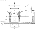
- FIG 2 is a sectional view taken along the A-A' line illustrated in Figure 1A and illustrates a state in which a chemical container part 1 is stored in the storage portion 30 in the holding member 10.
- a suitable syringe piston hereinafter, sometimes simply written as "piston” 1 is illustrated in the figure.
- the storage portion 30 is provided with: a first opening end portion 31 forming a loading and unloading mouth for the part 1 at a protruded tip of the storage portion 30; a second opening end portion 32 formed at a base end of the storage portion 30 by the second surface 20b of the substrate portion 20; and a bulging portion 33 where an inner wall face 30a of the storage portion 30 on a side of the first opening end portion 31 bulges in a direction of an inside of the cylinder.
- the loading and unloading mouth formed by the first opening end portion 31 is an inserting mouth for the part 1 into the storage portion 30 and an unloading mouth for the part 1 inserted into the storage portion 30. Since the storage portion 30 is provided with the first opening end portion 31 and the second opening end portion 32 both of which are open to form a communicating cylindrical shape, steam, a gas, radial rays, and the like which can be used for a sterilization treatment easily get into the storage portion 30 so that a sterilization treatment can be performed to the part 1 stored in the storage portion 30. In addition, the part 1 stored in the storage portion 30 can be perforated in a direction from the opening of the second opening end portion 32 toward the loading and unloading mouth at the first opening end portion 31 using the above-described automatic assembler.
- the bulging portion 33 may be the non-continuously formed bulging portion 33 in addition to the bulging portion 33 continuously formed in the form of a circle in a circumferential direction at the inner wall face 30a of the storage portion 30. Among these, the bulging portion 33 continuously formed in the form of a circle in the circumferential direction is preferable.
- the holding member 10 is more suitable as the piston holding member 10.
- a plunger is inserted in the piston 1, and the piston 1 is provided with a fixing hole (more suitably, screwing hole) for fixing the plunger inserted therein in some cases.
- a depression or a protruded portion for smoothly sliding the piston 1, which is fixed to the plunger, along a wall face inside of a barrel (injection cylinder) is provided in a circumferential direction at the outer circumferential face of the piston 1 in some cases.
- the piston is preferably inserted into the loading and unloading mouth formed by the first opening end portion 31 of the storage portion 30 from the side of a fixing hole 1a of the piston 1.
- the fixing hole 1a of the piston 1 be positioned on the side of the second opening end portion 32 of the storage portion 30, and a liquid contact portion 1b (portion where piston 1 comes into contact with chemical liquid in syringe) of the piston 1 be positioned on the side of the first opening end portion 31 of the storage portion 30.
- the conventional piston nest as described in Patent Literature 1 described previously adopts means for holding a piston in a storage portion by the engagement of a depression formed along the circumferential direction at the outer circumferential face of the piston to be stored in the storage portion and a bulging portion formed in the inner wall face of the storage portion.
- the holding member 10 is provided with the storage portion 30, which will be described below, and thereby can hold the part 1 in the storage portion 30 even when the part 1 is a piston without a depression, a piston having a very small depression, or the like, and unintended detachment of the part 1 from the storage portion 30 can be suppressed.
- the storage portion 30 in the holding member 10 has constitution of any one or both of the first aspect and the second aspect, which will be described below, and the storage portion 30 preferably has constitution of both of the first aspect and the second aspect.
- the holding member 10 provided with the storage portion 30 having the constitution of both of the first aspect and the second aspect is illustrated as an example.
- the storage portion 30 of the first aspect is a constitution aspect of the shape of the storage portion 30 itself. That is, as illustrated in Figure 2 , the storage portion 30 of the first aspect is provided with: a bulging portion 33 where the inner wall face 30a of the storage portion 30 on the side of the first opening end portion 31 bulges continuously from the first opening end portion 31 in the direction of the inside of the cylinder, thereby forming an opening widened toward the first opening end portion 31; and a tapered-off portion 34 where the inner wall face 30a of the storage portion 30 on the side of the second opening end portion 32 is formed in such a way as to narrow toward the second opening end portion 32.
- the bulging portion 33 where the inner wall face 30a of the storage portion 30 on the side of the first opening end portion 31 bulges in the direction of the inside of the cylinder is continuously provided from the first opening end portion 31, thereby forming an opening widened toward the first opening end portion 31. Therefore, the loading and unloading mouth formed by the first opening end portion 31 widens, so that loading and unloading the part 1 into and from the storage portion 30 can be made easy.
- the bulging portion 33 exists on the side of the first opening end portion 31 which is a protruded tip of the storage portion 30, and therefore when the part 1 is loaded into and unloaded from the storage portion 30, the part 1 pushes the bulging portion 33 toward the outside of the cylinder and can slightly bend the storage portion 30.
- the storage portion 30 of the first aspect is provided with the bulging portion 33 and the tapered-off portion 34, and therefore when the part 1 is stored in the storage portion 30 such that the whole part 1 falls therein, the bulging portion 33, the tapered-off portion 34, and the second opening end portion 32 function as a stopper for the part 1. Thereby, unintended detachment of the part 1 from the storage portion 30 can be suppressed.
- this storage portion 30 is provided with the bulging portion 33 and the tapered-off portion 34 functioning as a stopper for the part 1, and therefore a portion between the bulging portion 33 and the tapered-off portion 34 in an axial direction Z of the cylinder of the storage portion 30 can be made to have a size by which a slight gap can be generated between the inner wall face 30a of the storage portion 30 and the part 1.
- steam, a gas, and the like which can be used for a sterilization treatment diffuse around the part 1, and therefore the sterilization treatment can be performed to the part 1 sufficiently and effectively
- the storage portion 30 which satisfies the constitution of the second aspect, which will be described below, can also be obtained easily by inventing the constitution of the storage portion 30 of the first aspect.
- the storage portion 30 of the second aspect is a constitution aspect of the storage portion 30 in terms of a viewpoint of the relationship with a chemical container part to be stored in the storage portion 30. That is, as illustrated in Figure 2 , in the size in the direction XY orthogonal to the axial direction Z of the cylinder of the storage portion 30, the inner size D 31 of the first opening end portion 31 and the inner size D 35 of an intermediate portion 35 between the bulging portion 33 and the second opening end portion 32 are constituted in such a way as to be larger than the outer size D 1 of the part 1.
- the storage portion 30 is such that the inner size D 33 at a position where the bulging portion 33 is provided (hereinafter, sometimes written as "inner size of the bulging portion") and the inner size D 32 of the second opening end portion 32 are constituted in such a way as to be smaller than the outer size D 1 of the part 1.
- any of the respective inner sizes D 31 , D 32 , D 33 , and D 35 , and the outer size D 1 of the part 1 is a size in the direction XY orthogonal to the axial direction Z of the cylinder of the storage portion 30.
- the inner size means a size of an inside
- the outer size means a size of an outside.
- the inner size D 31 of the first opening end portion 31 has the same meaning as the size of the loading and unloading mouth formed by the first opening end portion 31.
- the inner size D 32 of the second opening end portion 32 has the same meaning as the size of the opening formed by the second surface 20b of the substrate portion 20.
- the inner size D 33 at the position where the bulging portion 33 is provided means an inner size at a position where the bulging portion 33 bulges to the maximum in a direction of the inside of the cylinder.
- the intermediate portion 35 between the bulging portion 33 and the second opening end portion 32 means a regional portion, in the axial direction Z of the cylinder of the storage portion 30, from a portion corresponding to a base (or may also be referred to as foot or bottom) on the side of the second opening end portion 32 in the bulging portion 33 to a portion of the side of the second opening end portion 32 (including a case where the portion is the tapered-off portion 34), the portion being set in such a way as to have a size smaller than the outer size of the part 1.
- the median value in the range from the maximum value to the minimum value of the inner size of this regional portion is defined as the inner size D 35 of the intermediate portion 35.
- each "inner size” in this case means an “inner diameter”, but the storage portion 30 may have, for example, a square cylindrical shape or the like, and therefore the “inner size” is described in some cases in the present specification.
- the part (syringe piston) 1 illustrated in Figure 2 has an approximately columnar shape, the "outer size of the part” in this case means the “outer diameter of the part", but the part 1 may have, for example, a square pillar shape or the like, and therefore the "outer size of the part” is described in some cases in the present specification.
- the outer size of the part 1 is not constant, such as a case where a depression is formed at the outer circumferential face, but in that case, the "outer size of the part” means the maximum outer size of the part 1 in the size in the direction XY orthogonal to the axial direction Z of the cylinder of the storage portion 30.
- the inner size D 31 of the first opening end portion 31 forming the loading and unloading mouth for the part 1 at the protruded tip of the storage portion 30 is larger than the outer size D 1 of the part 1, and therefore the part 1 is easily loaded into and unloaded from the storage portion 30.
- the inner size D 33 of the bulging portion 33 is smaller than the outer size D 1 of the part 1, but the bulging portion 33 is provided on the side of the first opening end portion 31 which is a protruded tip of the storage portion 30, and thereby when the part 1 is loaded into and unloaded from the storage portion 30, the bulging portion 33 is pushed toward the outside of the cylinder by the part 1, and the storage portion 30 can be thereby bent slightly. Therefore, loading and unloading the part 1 into and from the storage portion 30 can be made easy.
- the inner size D 35 of the intermediate portion between the bulging portion 33 in the storage portion 30 and the second opening end portion 32 is larger than the outer size D 1 of the part 1, and therefore when the part 1 is stored such that the whole part 1 falls in the storage portion 30, a slight gap can be generated between the inner wall face 30a of the storage portion 30 and the part 1 in the intermediate portion 35.
- steam, a gas, and the like which can be used for a sterilization treatment diffuse around the part 1, and therefore the sterilization treatment can be performed to the part 1 sufficiently and effectively.
- the inner size D 33 of the bulging portion 33 and the inner size D 32 of the second opening end portion 32 are smaller than the outer size D 1 of the part 1, and therefore when the part 1 is stored in the storage portion 30 such that the whole part 1 falls in the storage portion 30, the bulging portion 33 and the second opening end portion 32 function as a stopper for the part 1. Thereby, unintended detachment of the part 1 stored in the storage portion 30 can be suppressed.
- the inner wall face 30a of the storage portion 30 on the side of the first opening end portion 31 preferably bulges continuously from the first opening end portion 31 in the direction of the inside of the cylinder, thereby forming an opening widened toward the first opening end portion 31.
- the storage portion 30 of the second aspect as well as the storage portion 30 of the first aspect is preferably provided with a tapered-off portion 34 where the inner wall face 30a of the storage portion 30 on the side of the second opening end portion 32 is formed in such a way as to narrow toward the second opening portion 32.
- the second opening end portion 32 having an inner size D 32 smaller than the outer size D 1 of the part 1 is easily obtained.
- the inner wall face 30a of the storage portion 30 on the side of the second opening end portion 32 in such a way as to narrow toward the second opening end portion 32 in the same manner as in the storage portion 30 of the first aspect, there is also a structural advantage in production that there is no need to make the structure of a metal mold for use in producing the holding member 10 by injection molding or the like complicated such that the metal mold is divided at a position where the bulging portion 33 bulges most.
- the inner wall face 30a of the storage portion 30 on the side of the first opening end portion 31 may not be continuous from the first opening end portion 31, and the opening widened toward the first opening end portion 31 may not be formed.
- the storage portion 30 of the second aspect does not have to be provided with the above-described tapered-off portion 34.
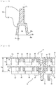
- the constitution of a holding member 11 provided with a storage portion 36 such as the one described above is illustrated in Figure 3 as one example of the constitution according to a modified example of the storage portion 30 of the second aspect.
- the storage portion 36 illustrated in Figure 3 is provided with: a first opening end portion 31A; a bulging portion 33A formed discontinuously from the first opening end portion 31A on the side of the first opening end portion 31A; and a second opening end portion 32A, wherein an inner wall face 36a of the storage portion 36 is formed into a tapered shape (storage portion 36 has reversely tapered shape) from the first opening end portion 31A toward the second opening end portion 32A.
- the inner size (inner diameter) D 31 of the first opening end portion 31 is preferably larger than the inner size (inner diameter) D 35 of the intermediate portion 35 between the bulging portion 33 and the second opening end portion 32.
- the inner size (inner diameter) D 32 of the second opening end portion 32 is preferably equal to or smaller than the inner size (inner diameter) D 33 at the position where the bulging portion 33 is provided.
- the inner size D 33 of the bulging portion 33 is preferably smaller than the minimum value of the tolerance of the outer size D 1 of the piston by 0.01 to 0.5 mm (more preferably 0.02 to 0.4 mm, and still more preferably 0.05 to 0.2 mm).
- the height of the bulging portion 33 is preferably 0.1 to 0.5 mm, and more preferably 0.1 to 0.3 mm based on the inner wall face 30a at a position corresponding to the inner size D 35 of the intermediate portion 35.
- connection libs 40 outside the cylinder of each of the storage portions 30, the connection libs 40 each connecting adjacent storage portions 30 in a plurality of the storage portions 30.
- connection libs 40 illustrated as an example in Figure 1 include parallel connection libs 41 each connecting storage portions 30 adjacent in a direction parallel to one side of the substrate portion 20 and inclined connection libs 42 each connecting the storage portions 30 adjacent in an oblique direction.
- connection lib 40 is formed integrally with the outer wall face 30b of the storage portion 30, and the connection lib 40 as well as the storage portion 30 is preferably provided to be approximately vertical to the first surface 20a of the substrate portion 20.
- connection lib 40 may be provided apart from the first surface 20a of the substrate portion 20 as long as the connection lib 40 connects adjacent storage portions 30 at outer wall faces 30b of the adjacent storage portions 30, or as illustrated in the figure, the connection lib 40 may be stood on the first surface 20a of the substrate portion 20.
- the holding member 10 may be subjected to conveyance, a sterilization treatment, assembly of a chemical container, and other processes while being in a state in which the part 1 is held in each of a plurality of storage portions 30 in some cases, and therefore load may be applied to the holding member 10 in some cases.
- load may be applied to the holding member 10 in some cases.
- the connection libs 40 are provided in the holding member 10
- the strength of the whole holding member 10 can be enhanced and deformation (distortion) of the holding member 10 can be suppressed. Therefore, for example, even when the part 1 stored in the storage portion 30 is perforated using an automatic assembler, the part 1 can be smoothly perforated and a chemical container can be smoothly assembled combining the part 1 with another part.
- connection lib 40 is preferably formed at a position lower than the height from the first surface 20a of the substrate portion 20 to the position of the bulging portion 33 of the storage portion 30 such that the storage portion 30 can be slightly bent as described previously when the part 1 is loaded into and unloaded from the storage portion 30 while the above-described effect of the connection lib 40 is maintained.
- the holding member 10 is obtained by injection molding or the like, the product (holding member 10) can be easily released from a metal mold by preparing the connection lib 40 having such height.
- the holding member 10 is preferably further provided with a plurality of supporting pillars 50 each formed on the side of the first surface 20a of the substrate portion 20 in such a way as to protrude higher than the storage portion 30.
- the supporting pillars 50 are preferably provided such that the holding member 10, when accommodated in a box type container, which will be described later, can stably stand to the bottom face of the box type container or preferably provided at the position and in the number (4 in Figure 1 ) of the supporting pillars 50 in consideration of the balance of the strength of the holding member 10, or other properties.
- the storage portion 30 can be thereby made into a non-contact state to a face where the holding member 10 is placed when the holding member 10 is placed with the side of the first face 20a of the substrate portion 20 facing downward. Therefore, a sterilization treatment of the part 1 stored in the state can be performed more effectively.
- Figure 4 illustrates an enlarged diagram of the region B illustrated in Figure 1A
- Figure 5 illustrates a sectional view taken along the C-C' line in Figure 4
- Figure 6 illustrates an enlarged sectional view illustrating a state in the vicinity of supporting pillars 50 at the time when two holding members 10 according to one embodiment of the present invention are stacked.
- the holding member 10 is preferably further provided with recessed portions 51 each provided at a position on the side of the second surface 20b of the substrate portion 20, the position corresponding to each of the supporting pillars 50 provided on the side of the surface 20a, in such a way as to be recessed toward an inside of each of the supporting pillars 50.
- a supporting pillar 50 of another holding member 10 is accommodated in one of these recessed portions 51.
- the supporting pillars 50 each illustrated as an example in Figure 4 to Figure 6 are each provided with: a pedestal portion 52 from the substrate portion 20 up to a predetermined height; and a connection portion 53 from the pedestal portion 52 up to the tip, wherein the previously described recessed portion 51 is provided in the pedestal portion 52.
- the connection portion 53 is formed into a cross square pillar shape, but the shape of the connection portion 53 is not particularly limited and may be an approximately columnar shape, an approximately elliptic column shape, an approximately rectangular, square pillar shape, or the like.
- the pedestal portion 52 is formed into an approximately columnar shape, but the shape of the pedestal portion 52 is not particularly limited and may be an approximately elliptic column shape or an approximately square pillar shape.
- the sectional shapes of the recessed portion 51, the pedestal portion 52, and the connection portion 53 are each preferably an approximately trapezoidal shape, and more preferably an isosceles trapezoidal shape in the longitudinal section of the supporting pillar 50.
- an angle ⁇ 1 made by a leg of the trapezoidal shape and a perpendicular line to the substrate portion 20 is preferably 1 to 10 degrees, and more preferably 2 to 7 degrees.
- an angle ⁇ 2 made by a leg of the trapezoidal shape and a perpendicular line to the substrate portion 20 is preferably 5 to 30 degrees, and more preferably 10 to 20 degrees.
- a depth H 51 of the recessed portion 51 from the second surface 20b of the substrate portion 20 is preferably smaller than a difference (H 50 - H 30 ) between a height H 50 of the supporting pillar 50 from the second surface 20b of the substrate portion 20 and a height H 30 of the storage portion 30 from the second surface 20b (H 51 ⁇ H 50 - H 30 ).
- the depth H 51 of the recessed portion 51 is preferably 20 to 50% (0.2 to 0.5 times the H 50 ), and more preferably 30 to 40% (0.3 to 0.4 times the H 50 ) of the height H 50 of the supporting pillar 50. Further, the depth H 51 of the recessed portion 51 is preferably 60 to 99% (0.6 to 0.99 times the difference described later), more preferably 70 to 95% (0.7 to 0.95 times the difference described later), and still more preferably 70 to 90% (0.7 to 0.9 times the difference described later) of a difference between the height H 50 of the supporting pillar 50 and the height H 30 of the storage portion 30 (H 50 - H 30 ).
- the gap between the storage portion 30 of one holding member 10 and another holding member 10 can be made smaller when a plurality of holding members 10 are stacked using the supporting pillars 50 and the recessed portions 51. Therefore, when the holding members 10 are stacked and accommodated in a box type container, which will be described later, the number of holding members 10 which can be accommodated can be increased, and about 7 holding members 10 can be stacked in one box type container.
- the gap is preferably 0.1 to 4 mm, more preferably 0.5 to 3 mm, and still more preferably 1 to 3 mm.
- the holding member 10 is provided with any one or both of the constitution of the first aspect and the constitution of the second aspect, and therefore the part 1 is easily loaded into and unloaded from the storage portion 30, and sudden detachment of the part 1 from the storage portion 30 can be suppressed.
- this holding member 10 a sterilization treatment of the part 1 can be performed effectively.
- this holding member 10, as will be described next, can be provided for storage, conveyance, and a sterilization treatment of the chemical container part 1 , and assembly into a chemical container, and other processes as a packaging structure in which the holding member 10 is accommodated, in a state of holding chemical container parts 1, in a box type container.
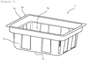
- Figure 7 is a perspective view illustrating one example of a box type container 7 which can be used for a packaging structure of chemical container parts according to one embodiment of the present invention.
- Figure 8 is a plan view of a packaging structure 100 using the box type container 7 illustrated in Figure 7 , the plan view viewed from a side of an opening portion 7a of the box type container 7.
- the packaging structure 100 of chemical container parts according to one embodiment of the present invention is provided with: the box type container 7 having the opening portion 7a; the holding member 10 according to the previously described embodiment accommodated in the box type container 7; and the chemical container parts 1 stored in the storage portions 30 in the holding member 10.
- a plurality of parts 1 can be thereby provided for conveyance, a sterilization treatment, and the like in a state in which the plurality of parts 1 are stored in the storage portions 30 in the holding member 10.
- Steam, a gas, or the like can be filled in an inside 7b of the box type container 7, and therefore by using the box type container 7, a sterilization treatment can be performed more effectively.
- the shape of the box type container 7 is not particularly limited as long as the shape is a box (basket) type which has the opening portion 7a to be a loading and unloading mouth for the holding member 10 at an upper portion and in which the holding member 10 can be accommodated in the inside 7b.
- the planar shape of the box type container 7 is usually an approximately rectangular shape, but may be an approximately circular shape, an approximately elliptical shape, an approximately polygonal shape, or the like.
- the material of the box type container 7 is not particularly limited, and the box type container 7 is usually made of a synthetic resin but may be made of a metal, or a composite material of a metal and a synthetic resin or the like.
- a recessed or protruded shape is preferably provided at a bottom portion 7c or a side face 7e of the box type container 7 in order to enhance the strength of the box type container 7, thereby preventing deformation.
- the holding member 10 When the holding member 10 is accommodated in the box type container 7, the holding member 10 is preferably accommodated in the box type container 7 such that the side of the first surface 20a of the substrate portion 20 in the holding member 10 oppositely faces the bottom face (inner face of bottom portion 7c) of the box type container 7.
- a plurality of (two or more) holding members 10 are preferably stacked and accommodated in the box type container 7, and for example, about 2 to about 7 holding members 10 are preferably stacked and accommodated in the box type container 7.
- a plurality of holding members 10 can be stacked by combining the recessed portions 51 of one holding member 10 and the supporting pillars 50 of another holding member 10, and therefore about 7 holding members 10 can be stacked in one box type container 7.
- the storage portion 30 of the holding member 10 can be made into a non-contact state to another holding member 10, as described previously. Therefore, also, in a state in which a plurality of holding members 10 are accommodated in the box type container 7, an effective sterilization treatment can also be performed to the parts 1 stored in the storage portions 30.
- the packaging structure 100 is preferably further provided with a gas impermeable film (not illustrated in figures) sealing the opening portion 7a of the box type container 7.
- the gas impermeable film can seal the opening portion 7a at the upper portion of the box type container 7 by releasably sealing a ring-shaped flange portion 7d of the box type container 7.
- a gas impermeable film a high-density polyethylene film, a polyethylene terephthalate film, and the like, and a laminated film or the like of a plurality of resin films including at least any one of the films can be used.
- the box type container 7 can be wrapped and the opening portion 7a can also be sealed.
- the sterilizable film is a film which permeates gases for sterilization, such as a gas and steam, but does not permeate germs, and the sterilizable film is constituted, for example, by a filament of high-density polyethylene or other polymers.
- Tyvek (R) manufactured by E.I. du Pont De Nemours and Company, and the like can be used.
- the holding member according to one embodiment of the present invention can have the following constitution.
Landscapes
- Health & Medical Sciences (AREA)
- Life Sciences & Earth Sciences (AREA)
- Animal Behavior & Ethology (AREA)
- General Health & Medical Sciences (AREA)
- Public Health (AREA)
- Veterinary Medicine (AREA)
- Engineering & Computer Science (AREA)
- Biomedical Technology (AREA)
- Vascular Medicine (AREA)
- Anesthesiology (AREA)
- Heart & Thoracic Surgery (AREA)
- Hematology (AREA)
- Pharmacology & Pharmacy (AREA)
- Mechanical Engineering (AREA)
- Diabetes (AREA)
- Infusion, Injection, And Reservoir Apparatuses (AREA)
- Medical Preparation Storing Or Oral Administration Devices (AREA)
- Apparatus For Disinfection Or Sterilisation (AREA)
Applications Claiming Priority (1)
| Application Number | Priority Date | Filing Date | Title |
|---|---|---|---|
| JP2018020755A JP6694900B2 (ja) | 2018-02-08 | 2018-02-08 | 保持部材、及び注射器用ピストンのパッケージング構造 |
Publications (2)
| Publication Number | Publication Date |
|---|---|
| EP3524293A1 true EP3524293A1 (de) | 2019-08-14 |
| EP3524293B1 EP3524293B1 (de) | 2022-04-20 |
Family
ID=65493798
Family Applications (1)
| Application Number | Title | Priority Date | Filing Date |
|---|---|---|---|
| EP19154783.5A Active EP3524293B1 (de) | 2018-02-08 | 2019-01-31 | Halteelement und verpackungsstruktur von spritzenkolben |
Country Status (7)
| Country | Link |
|---|---|
| US (1) | US10918784B2 (de) |
| EP (1) | EP3524293B1 (de) |
| JP (1) | JP6694900B2 (de) |
| CN (1) | CN110127180B (de) |
| DK (1) | DK3524293T3 (de) |
| ES (1) | ES2912358T3 (de) |
| HU (1) | HUE059525T2 (de) |
Cited By (2)
| Publication number | Priority date | Publication date | Assignee | Title |
|---|---|---|---|---|
| WO2022162003A1 (en) | 2021-01-26 | 2022-08-04 | Becton Dickinson France | A tub for the packaging of a plurality of nests of plunger stoppers with guiding features ensuring a reliable location of the nests within the tub |
| WO2022161992A1 (en) | 2021-01-26 | 2022-08-04 | Becton Dickinson France | A nest for the packaging of plunger stoppers with stacking pins ensuring a reliable alignment of a pile of nests |
Families Citing this family (10)
| Publication number | Priority date | Publication date | Assignee | Title |
|---|---|---|---|---|
| US12515832B2 (en) * | 2013-08-16 | 2026-01-06 | Vanrx Pharmasystems Inc. | Method, device and system for filling pharmaceutical containers |
| EP3407934B1 (de) | 2016-01-27 | 2025-06-18 | West Pharmaceutical Services, Inc. | Spritzenhalterung mit hexagonalen röhren und verschiebung der mittelpunkte |
| CN216402234U (zh) * | 2020-01-10 | 2022-04-29 | 肖特瑞士股份公司 | 用于药品次级包装的运输的分隔层和运输系统 |
| EP4284460A1 (de) * | 2021-01-26 | 2023-12-06 | Becton Dickinson France | Nester zum verpacken von kolbenstopfen mit integrierten stapelmerkmalen zur sicheren ausrichtung eines stapels von nestern |
| JP2024505026A (ja) * | 2021-01-26 | 2024-02-02 | ベクトン ディキンソン フランス | タブ内の複数のネストの確実な整列を保証するクリップ付きプランジャーストッパの包装用のネスト |
| CN113509380A (zh) * | 2021-04-22 | 2021-10-19 | 绵竹市人民医院 | 一种医用药物放置盒 |
| JPWO2024105914A1 (de) * | 2022-11-14 | 2024-05-23 | ||
| WO2024105915A1 (ja) * | 2022-11-14 | 2024-05-23 | テルモ株式会社 | ガスケット保持具、ガスケット保持具セット及びガスケット収容体 |
| IT202300021390A1 (it) * | 2023-10-13 | 2025-04-13 | Biopap S R L | Metodo e gruppo di assemblaggio per la realizzazione di vassoi |
| US20250136325A1 (en) * | 2023-10-30 | 2025-05-01 | West Pharmaceutical Services, Inc. | Packaging for containers |
Citations (7)
| Publication number | Priority date | Publication date | Assignee | Title |
|---|---|---|---|---|
| WO2007099649A1 (ja) | 2006-02-28 | 2007-09-07 | Daikyo Seiko, Ltd. | 注射器用ピストンネスト |
| WO2008107961A1 (ja) | 2007-03-05 | 2008-09-12 | Daikyo Seiko, Ltd. | 医療用容器 |
| WO2009015862A1 (en) * | 2007-08-02 | 2009-02-05 | Semafra S.A. | Package structure for glass containers for pharmaceutical use |
| WO2010062602A1 (en) * | 2008-10-28 | 2010-06-03 | West Pharmaceutical Services, Inc. | Syringe piston nest for the manufacture of pre filled syringe |
| WO2013084791A1 (ja) * | 2011-12-05 | 2013-06-13 | テルモ株式会社 | ガスケット収納容器 |
| WO2014009037A1 (de) * | 2012-07-13 | 2014-01-16 | Schott Ag | Haltestruktur zum gleichzeitigen halten einer mehrzahl von behältern für substanzen für medizinische, pharmazeutische oder kosmetische anwendungen sowie transport- oder verpackungsbehälter mit selbiger |
| WO2016111698A1 (en) * | 2015-01-09 | 2016-07-14 | West Pharmaceutical Services, Inc. | Covers for drug container piston arrays or piston nests and packages for cover and piston nest assemblies |
Family Cites Families (9)
| Publication number | Priority date | Publication date | Assignee | Title |
|---|---|---|---|---|
| US4349109A (en) * | 1980-10-20 | 1982-09-14 | Medical Laboratory Automation, Inc. | Disposable pipette tips and trays therefor |
| EP2453947B1 (de) * | 2009-07-15 | 2018-06-13 | Becton Dickinson France | Ablage zur positionierung länglicher objekte, im besonderen spritzenkörper oder spritzen |
| DE102011104300A1 (de) * | 2011-03-18 | 2012-09-20 | Schott Schweiz Ag | Trägerplatte und Transport- und/oder Lagereinrichtung für pharmazeutische Behältnisse |
| WO2012143533A1 (en) * | 2011-04-21 | 2012-10-26 | Becton Dickinson France | Packaging for medical containers |
| ITVI20120215A1 (it) * | 2012-08-30 | 2014-03-01 | Fedegari Autoclavi | Struttura per il confezionamento di componenti per contenitori ad uso farmaceutico |
| CA2981231C (en) * | 2015-04-17 | 2021-02-23 | Anil Narayan Narvekar | Supporting structure for sealed cartridges, transport or packaging container and process |
| US11179296B2 (en) | 2015-09-04 | 2021-11-23 | Daikyo Seiko, Ltd. | Container holding member and medical container set |
| WO2017170636A1 (ja) * | 2016-03-31 | 2017-10-05 | テルモ株式会社 | シリンジ保持部材、シリンジ梱包体及びシリンジ梱包体の組立方法 |
| US10874473B2 (en) | 2016-04-28 | 2020-12-29 | Daikyo Seiko Ltd. | Container |
-
2018
- 2018-02-08 JP JP2018020755A patent/JP6694900B2/ja active Active
- 2018-12-21 US US16/230,043 patent/US10918784B2/en not_active Expired - Fee Related
-
2019
- 2019-01-30 CN CN201910093842.9A patent/CN110127180B/zh active Active
- 2019-01-31 DK DK19154783.5T patent/DK3524293T3/da active
- 2019-01-31 ES ES19154783T patent/ES2912358T3/es active Active
- 2019-01-31 HU HUE19154783A patent/HUE059525T2/hu unknown
- 2019-01-31 EP EP19154783.5A patent/EP3524293B1/de active Active
Patent Citations (8)
| Publication number | Priority date | Publication date | Assignee | Title |
|---|---|---|---|---|
| WO2007099649A1 (ja) | 2006-02-28 | 2007-09-07 | Daikyo Seiko, Ltd. | 注射器用ピストンネスト |
| EP1990068A1 (de) * | 2006-02-28 | 2008-11-12 | Daikyo Seiko, LTD. | Kolbennest für ein injektionsgerät |
| WO2008107961A1 (ja) | 2007-03-05 | 2008-09-12 | Daikyo Seiko, Ltd. | 医療用容器 |
| WO2009015862A1 (en) * | 2007-08-02 | 2009-02-05 | Semafra S.A. | Package structure for glass containers for pharmaceutical use |
| WO2010062602A1 (en) * | 2008-10-28 | 2010-06-03 | West Pharmaceutical Services, Inc. | Syringe piston nest for the manufacture of pre filled syringe |
| WO2013084791A1 (ja) * | 2011-12-05 | 2013-06-13 | テルモ株式会社 | ガスケット収納容器 |
| WO2014009037A1 (de) * | 2012-07-13 | 2014-01-16 | Schott Ag | Haltestruktur zum gleichzeitigen halten einer mehrzahl von behältern für substanzen für medizinische, pharmazeutische oder kosmetische anwendungen sowie transport- oder verpackungsbehälter mit selbiger |
| WO2016111698A1 (en) * | 2015-01-09 | 2016-07-14 | West Pharmaceutical Services, Inc. | Covers for drug container piston arrays or piston nests and packages for cover and piston nest assemblies |
Cited By (4)
| Publication number | Priority date | Publication date | Assignee | Title |
|---|---|---|---|---|
| WO2022162003A1 (en) | 2021-01-26 | 2022-08-04 | Becton Dickinson France | A tub for the packaging of a plurality of nests of plunger stoppers with guiding features ensuring a reliable location of the nests within the tub |
| WO2022161992A1 (en) | 2021-01-26 | 2022-08-04 | Becton Dickinson France | A nest for the packaging of plunger stoppers with stacking pins ensuring a reliable alignment of a pile of nests |
| CN117062755A (zh) * | 2021-01-26 | 2023-11-14 | 贝克顿迪金森法国公司 | 用于包装柱塞止挡件的多个嵌套件、具有确保嵌套件在盒体内的可靠位置的引导特征的盒体 |
| US12239815B2 (en) | 2021-01-26 | 2025-03-04 | Becton Dickinson France | Tub for the packaging of a plurality of nests of plunger stoppers with guiding features ensuring a reliable location of the nests within the tub |
Also Published As
| Publication number | Publication date |
|---|---|
| CN110127180B (zh) | 2022-12-02 |
| JP6694900B2 (ja) | 2020-05-20 |
| CN110127180A (zh) | 2019-08-16 |
| EP3524293B1 (de) | 2022-04-20 |
| DK3524293T3 (da) | 2022-05-23 |
| ES2912358T3 (es) | 2022-05-25 |
| US20190240395A1 (en) | 2019-08-08 |
| JP2019136214A (ja) | 2019-08-22 |
| US10918784B2 (en) | 2021-02-16 |
| HUE059525T2 (hu) | 2022-11-28 |
Similar Documents
| Publication | Publication Date | Title |
|---|---|---|
| EP3524293B1 (de) | Halteelement und verpackungsstruktur von spritzenkolben | |
| US20220071846A1 (en) | Container holding member and medical container set | |
| CN109071091B (zh) | 容器 | |
| KR102749798B1 (ko) | 의료용 기기 컨테이너 | |
| EP3922284A1 (de) | Ablage für fertigspritze und verpackung damit | |
| US10434242B2 (en) | Covers for drug container piston arrays or piston nests and packages for cover and piston nest assemblies | |
| US9468587B2 (en) | Tray and packaging for medical containers | |
| CN101652152A (zh) | 医用容器 | |
| JP2019198650A (ja) | 薬学、医学または化粧用に使用される物質のための複数の容器を同時に保持するための保持構造ならびに保持構造を備えた搬送構造体 | |
| US12006125B2 (en) | Container for packaging units | |
| US20190298610A1 (en) | Holding structure for concurrently holding a plurality of containers for substances for pharmaceutical, medical or cosmetic applications, transport structure and transport or packaging container comprising the same | |
| US10744066B2 (en) | Overcap intended for a pharmaceutical container | |
| WO2013129278A1 (ja) | シリンジ収納容器及びシリンジ梱包体 | |
| EP4523720A1 (de) | Spritzenhalter und verpackung | |
| US20230025555A1 (en) | Pre-filled syringe stopper retainer having projections or receivers and methods of using same | |
| US20250144288A1 (en) | Device and System for Transporting Medical Devices | |
| JP2021102164A (ja) | 医療用機器コンテナー |
Legal Events
| Date | Code | Title | Description |
|---|---|---|---|
| PUAI | Public reference made under article 153(3) epc to a published international application that has entered the european phase |
Free format text: ORIGINAL CODE: 0009012 |
|
| STAA | Information on the status of an ep patent application or granted ep patent |
Free format text: STATUS: THE APPLICATION HAS BEEN PUBLISHED |
|
| AK | Designated contracting states |
Kind code of ref document: A1 Designated state(s): AL AT BE BG CH CY CZ DE DK EE ES FI FR GB GR HR HU IE IS IT LI LT LU LV MC MK MT NL NO PL PT RO RS SE SI SK SM TR |
|
| AX | Request for extension of the european patent |
Extension state: BA ME |
|
| STAA | Information on the status of an ep patent application or granted ep patent |
Free format text: STATUS: REQUEST FOR EXAMINATION WAS MADE |
|
| 17P | Request for examination filed |
Effective date: 20200213 |
|
| RBV | Designated contracting states (corrected) |
Designated state(s): AL AT BE BG CH CY CZ DE DK EE ES FI FR GB GR HR HU IE IS IT LI LT LU LV MC MK MT NL NO PL PT RO RS SE SI SK SM TR |
|
| STAA | Information on the status of an ep patent application or granted ep patent |
Free format text: STATUS: EXAMINATION IS IN PROGRESS |
|
| 17Q | First examination report despatched |
Effective date: 20200821 |
|
| GRAP | Despatch of communication of intention to grant a patent |
Free format text: ORIGINAL CODE: EPIDOSNIGR1 |
|
| STAA | Information on the status of an ep patent application or granted ep patent |
Free format text: STATUS: GRANT OF PATENT IS INTENDED |
|
| INTG | Intention to grant announced |
Effective date: 20210727 |
|
| GRAJ | Information related to disapproval of communication of intention to grant by the applicant or resumption of examination proceedings by the epo deleted |
Free format text: ORIGINAL CODE: EPIDOSDIGR1 |
|
| STAA | Information on the status of an ep patent application or granted ep patent |
Free format text: STATUS: EXAMINATION IS IN PROGRESS |
|
| INTC | Intention to grant announced (deleted) | ||
| GRAS | Grant fee paid |
Free format text: ORIGINAL CODE: EPIDOSNIGR3 |
|
| STAA | Information on the status of an ep patent application or granted ep patent |
Free format text: STATUS: GRANT OF PATENT IS INTENDED |
|
| GRAP | Despatch of communication of intention to grant a patent |
Free format text: ORIGINAL CODE: EPIDOSNIGR1 |
|
| INTG | Intention to grant announced |
Effective date: 20220118 |
|
| GRAA | (expected) grant |
Free format text: ORIGINAL CODE: 0009210 |
|
| STAA | Information on the status of an ep patent application or granted ep patent |
Free format text: STATUS: THE PATENT HAS BEEN GRANTED |
|
| AK | Designated contracting states |
Kind code of ref document: B1 Designated state(s): AL AT BE BG CH CY CZ DE DK EE ES FI FR GB GR HR HU IE IS IT LI LT LU LV MC MK MT NL NO PL PT RO RS SE SI SK SM TR |
|
| REG | Reference to a national code |
Ref country code: GB Ref legal event code: FG4D |
|
| REG | Reference to a national code |
Ref country code: CH Ref legal event code: EP |
|
| REG | Reference to a national code |
Ref country code: IE Ref legal event code: FG4D |
|
| REG | Reference to a national code |
Ref country code: DE Ref legal event code: R096 Ref document number: 602019013790 Country of ref document: DE |
|
| REG | Reference to a national code |
Ref country code: AT Ref legal event code: REF Ref document number: 1484681 Country of ref document: AT Kind code of ref document: T Effective date: 20220515 |
|
| REG | Reference to a national code |
Ref country code: DK Ref legal event code: T3 Effective date: 20220518 |
|
| REG | Reference to a national code |
Ref country code: ES Ref legal event code: FG2A Ref document number: 2912358 Country of ref document: ES Kind code of ref document: T3 Effective date: 20220525 |
|
| REG | Reference to a national code |
Ref country code: SE Ref legal event code: TRGR |
|
| REG | Reference to a national code |
Ref country code: LT Ref legal event code: MG9D |
|
| REG | Reference to a national code |
Ref country code: NO Ref legal event code: T2 Effective date: 20220420 |
|
| REG | Reference to a national code |
Ref country code: NL Ref legal event code: MP Effective date: 20220420 |
|
| PG25 | Lapsed in a contracting state [announced via postgrant information from national office to epo] |
Ref country code: NL Free format text: LAPSE BECAUSE OF FAILURE TO SUBMIT A TRANSLATION OF THE DESCRIPTION OR TO PAY THE FEE WITHIN THE PRESCRIBED TIME-LIMIT Effective date: 20220420 |
|
| PG25 | Lapsed in a contracting state [announced via postgrant information from national office to epo] |
Ref country code: PT Free format text: LAPSE BECAUSE OF FAILURE TO SUBMIT A TRANSLATION OF THE DESCRIPTION OR TO PAY THE FEE WITHIN THE PRESCRIBED TIME-LIMIT Effective date: 20220822 Ref country code: LT Free format text: LAPSE BECAUSE OF FAILURE TO SUBMIT A TRANSLATION OF THE DESCRIPTION OR TO PAY THE FEE WITHIN THE PRESCRIBED TIME-LIMIT Effective date: 20220420 Ref country code: HR Free format text: LAPSE BECAUSE OF FAILURE TO SUBMIT A TRANSLATION OF THE DESCRIPTION OR TO PAY THE FEE WITHIN THE PRESCRIBED TIME-LIMIT Effective date: 20220420 Ref country code: GR Free format text: LAPSE BECAUSE OF FAILURE TO SUBMIT A TRANSLATION OF THE DESCRIPTION OR TO PAY THE FEE WITHIN THE PRESCRIBED TIME-LIMIT Effective date: 20220721 Ref country code: FI Free format text: LAPSE BECAUSE OF FAILURE TO SUBMIT A TRANSLATION OF THE DESCRIPTION OR TO PAY THE FEE WITHIN THE PRESCRIBED TIME-LIMIT Effective date: 20220420 Ref country code: BG Free format text: LAPSE BECAUSE OF FAILURE TO SUBMIT A TRANSLATION OF THE DESCRIPTION OR TO PAY THE FEE WITHIN THE PRESCRIBED TIME-LIMIT Effective date: 20220720 |
|
| REG | Reference to a national code |
Ref country code: HU Ref legal event code: AG4A Ref document number: E059525 Country of ref document: HU |
|
| PG25 | Lapsed in a contracting state [announced via postgrant information from national office to epo] |
Ref country code: RS Free format text: LAPSE BECAUSE OF FAILURE TO SUBMIT A TRANSLATION OF THE DESCRIPTION OR TO PAY THE FEE WITHIN THE PRESCRIBED TIME-LIMIT Effective date: 20220420 Ref country code: PL Free format text: LAPSE BECAUSE OF FAILURE TO SUBMIT A TRANSLATION OF THE DESCRIPTION OR TO PAY THE FEE WITHIN THE PRESCRIBED TIME-LIMIT Effective date: 20220420 Ref country code: LV Free format text: LAPSE BECAUSE OF FAILURE TO SUBMIT A TRANSLATION OF THE DESCRIPTION OR TO PAY THE FEE WITHIN THE PRESCRIBED TIME-LIMIT Effective date: 20220420 Ref country code: IS Free format text: LAPSE BECAUSE OF FAILURE TO SUBMIT A TRANSLATION OF THE DESCRIPTION OR TO PAY THE FEE WITHIN THE PRESCRIBED TIME-LIMIT Effective date: 20220820 |
|
| REG | Reference to a national code |
Ref country code: DE Ref legal event code: R097 Ref document number: 602019013790 Country of ref document: DE |
|
| PG25 | Lapsed in a contracting state [announced via postgrant information from national office to epo] |
Ref country code: SM Free format text: LAPSE BECAUSE OF FAILURE TO SUBMIT A TRANSLATION OF THE DESCRIPTION OR TO PAY THE FEE WITHIN THE PRESCRIBED TIME-LIMIT Effective date: 20220420 Ref country code: SK Free format text: LAPSE BECAUSE OF FAILURE TO SUBMIT A TRANSLATION OF THE DESCRIPTION OR TO PAY THE FEE WITHIN THE PRESCRIBED TIME-LIMIT Effective date: 20220420 Ref country code: RO Free format text: LAPSE BECAUSE OF FAILURE TO SUBMIT A TRANSLATION OF THE DESCRIPTION OR TO PAY THE FEE WITHIN THE PRESCRIBED TIME-LIMIT Effective date: 20220420 Ref country code: EE Free format text: LAPSE BECAUSE OF FAILURE TO SUBMIT A TRANSLATION OF THE DESCRIPTION OR TO PAY THE FEE WITHIN THE PRESCRIBED TIME-LIMIT Effective date: 20220420 |
|
| PLBE | No opposition filed within time limit |
Free format text: ORIGINAL CODE: 0009261 |
|
| STAA | Information on the status of an ep patent application or granted ep patent |
Free format text: STATUS: NO OPPOSITION FILED WITHIN TIME LIMIT |
|
| 26N | No opposition filed |
Effective date: 20230123 |
|
| PG25 | Lapsed in a contracting state [announced via postgrant information from national office to epo] |
Ref country code: AL Free format text: LAPSE BECAUSE OF FAILURE TO SUBMIT A TRANSLATION OF THE DESCRIPTION OR TO PAY THE FEE WITHIN THE PRESCRIBED TIME-LIMIT Effective date: 20220420 |
|
| PG25 | Lapsed in a contracting state [announced via postgrant information from national office to epo] |
Ref country code: SI Free format text: LAPSE BECAUSE OF FAILURE TO SUBMIT A TRANSLATION OF THE DESCRIPTION OR TO PAY THE FEE WITHIN THE PRESCRIBED TIME-LIMIT Effective date: 20220420 |
|
| P01 | Opt-out of the competence of the unified patent court (upc) registered |
Effective date: 20230517 |
|
| PG25 | Lapsed in a contracting state [announced via postgrant information from national office to epo] |
Ref country code: LU Free format text: LAPSE BECAUSE OF NON-PAYMENT OF DUE FEES Effective date: 20230131 |
|
| PGFP | Annual fee paid to national office [announced via postgrant information from national office to epo] |
Ref country code: ES Payment date: 20240227 Year of fee payment: 6 |
|
| PGFP | Annual fee paid to national office [announced via postgrant information from national office to epo] |
Ref country code: AT Payment date: 20240122 Year of fee payment: 6 |
|
| PGFP | Annual fee paid to national office [announced via postgrant information from national office to epo] |
Ref country code: CZ Payment date: 20240119 Year of fee payment: 6 |
|
| PGFP | Annual fee paid to national office [announced via postgrant information from national office to epo] |
Ref country code: TR Payment date: 20240130 Year of fee payment: 6 Ref country code: SE Payment date: 20240119 Year of fee payment: 6 Ref country code: NO Payment date: 20240123 Year of fee payment: 6 |
|
| PG25 | Lapsed in a contracting state [announced via postgrant information from national office to epo] |
Ref country code: MC Free format text: LAPSE BECAUSE OF FAILURE TO SUBMIT A TRANSLATION OF THE DESCRIPTION OR TO PAY THE FEE WITHIN THE PRESCRIBED TIME-LIMIT Effective date: 20220420 |
|
| PG25 | Lapsed in a contracting state [announced via postgrant information from national office to epo] |
Ref country code: MC Free format text: LAPSE BECAUSE OF FAILURE TO SUBMIT A TRANSLATION OF THE DESCRIPTION OR TO PAY THE FEE WITHIN THE PRESCRIBED TIME-LIMIT Effective date: 20220420 |
|
| PG25 | Lapsed in a contracting state [announced via postgrant information from national office to epo] |
Ref country code: BG Free format text: LAPSE BECAUSE OF FAILURE TO SUBMIT A TRANSLATION OF THE DESCRIPTION OR TO PAY THE FEE WITHIN THE PRESCRIBED TIME-LIMIT Effective date: 20220420 |
|
| PG25 | Lapsed in a contracting state [announced via postgrant information from national office to epo] |
Ref country code: BG Free format text: LAPSE BECAUSE OF FAILURE TO SUBMIT A TRANSLATION OF THE DESCRIPTION OR TO PAY THE FEE WITHIN THE PRESCRIBED TIME-LIMIT Effective date: 20220420 |
|
| PGFP | Annual fee paid to national office [announced via postgrant information from national office to epo] |
Ref country code: HU Payment date: 20250123 Year of fee payment: 7 |
|
| PGFP | Annual fee paid to national office [announced via postgrant information from national office to epo] |
Ref country code: DE Payment date: 20250121 Year of fee payment: 7 |
|
| PGFP | Annual fee paid to national office [announced via postgrant information from national office to epo] |
Ref country code: DK Payment date: 20250124 Year of fee payment: 7 |
|
| PGFP | Annual fee paid to national office [announced via postgrant information from national office to epo] |
Ref country code: IE Payment date: 20250130 Year of fee payment: 7 |
|
| PGFP | Annual fee paid to national office [announced via postgrant information from national office to epo] |
Ref country code: CH Payment date: 20250201 Year of fee payment: 7 Ref country code: BE Payment date: 20250121 Year of fee payment: 7 |
|
| PGFP | Annual fee paid to national office [announced via postgrant information from national office to epo] |
Ref country code: FR Payment date: 20250127 Year of fee payment: 7 |
|
| PGFP | Annual fee paid to national office [announced via postgrant information from national office to epo] |
Ref country code: IT Payment date: 20250129 Year of fee payment: 7 Ref country code: GB Payment date: 20250128 Year of fee payment: 7 |
|
| PG25 | Lapsed in a contracting state [announced via postgrant information from national office to epo] |
Ref country code: CY Free format text: LAPSE BECAUSE OF FAILURE TO SUBMIT A TRANSLATION OF THE DESCRIPTION OR TO PAY THE FEE WITHIN THE PRESCRIBED TIME-LIMIT; INVALID AB INITIO Effective date: 20190131 |
|
| REG | Reference to a national code |
Ref country code: AT Ref legal event code: MM01 Ref document number: 1484681 Country of ref document: AT Kind code of ref document: T Effective date: 20250131 |
|
| REG | Reference to a national code |
Ref country code: SE Ref legal event code: EUG |
|
| PG25 | Lapsed in a contracting state [announced via postgrant information from national office to epo] |
Ref country code: NO Free format text: LAPSE BECAUSE OF NON-PAYMENT OF DUE FEES Effective date: 20250131 |
|
| PG25 | Lapsed in a contracting state [announced via postgrant information from national office to epo] |
Ref country code: AT Free format text: LAPSE BECAUSE OF NON-PAYMENT OF DUE FEES Effective date: 20250131 |
|
| PG25 | Lapsed in a contracting state [announced via postgrant information from national office to epo] |
Ref country code: CZ Free format text: LAPSE BECAUSE OF NON-PAYMENT OF DUE FEES Effective date: 20250131 |
|
| REG | Reference to a national code |
Ref country code: ES Ref legal event code: FD2A Effective date: 20260302 |
|
| PG25 | Lapsed in a contracting state [announced via postgrant information from national office to epo] |
Ref country code: ES Free format text: LAPSE BECAUSE OF NON-PAYMENT OF DUE FEES Effective date: 20250201 |