EP4523720A1 - Spritzenhalter und verpackung - Google Patents
Spritzenhalter und verpackung Download PDFInfo
- Publication number
- EP4523720A1 EP4523720A1 EP23835549.9A EP23835549A EP4523720A1 EP 4523720 A1 EP4523720 A1 EP 4523720A1 EP 23835549 A EP23835549 A EP 23835549A EP 4523720 A1 EP4523720 A1 EP 4523720A1
- Authority
- EP
- European Patent Office
- Prior art keywords
- syringe
- flange
- axis direction
- abutting
- tube
- Prior art date
- Legal status (The legal status is an assumption and is not a legal conclusion. Google has not performed a legal analysis and makes no representation as to the accuracy of the status listed.)
- Pending
Links
Images


Classifications
-
- A—HUMAN NECESSITIES
- A61—MEDICAL OR VETERINARY SCIENCE; HYGIENE
- A61M—DEVICES FOR INTRODUCING MEDIA INTO, OR ONTO, THE BODY; DEVICES FOR TRANSDUCING BODY MEDIA OR FOR TAKING MEDIA FROM THE BODY; DEVICES FOR PRODUCING OR ENDING SLEEP OR STUPOR
- A61M5/00—Devices for bringing media into the body in a subcutaneous, intra-vascular or intramuscular way; Accessories therefor, e.g. filling or cleaning devices, arm-rests
- A61M5/008—Racks for supporting syringes or needles
-
- A—HUMAN NECESSITIES
- A61—MEDICAL OR VETERINARY SCIENCE; HYGIENE
- A61M—DEVICES FOR INTRODUCING MEDIA INTO, OR ONTO, THE BODY; DEVICES FOR TRANSDUCING BODY MEDIA OR FOR TAKING MEDIA FROM THE BODY; DEVICES FOR PRODUCING OR ENDING SLEEP OR STUPOR
- A61M5/00—Devices for bringing media into the body in a subcutaneous, intra-vascular or intramuscular way; Accessories therefor, e.g. filling or cleaning devices, arm-rests
- A61M5/002—Packages specially adapted therefor, e.g. for syringes or needles, kits for diabetics
-
- A—HUMAN NECESSITIES
- A61—MEDICAL OR VETERINARY SCIENCE; HYGIENE
- A61J—CONTAINERS SPECIALLY ADAPTED FOR MEDICAL OR PHARMACEUTICAL PURPOSES; DEVICES OR METHODS SPECIALLY ADAPTED FOR BRINGING PHARMACEUTICAL PRODUCTS INTO PARTICULAR PHYSICAL OR ADMINISTERING FORMS; DEVICES FOR ADMINISTERING FOOD OR MEDICINES ORALLY; BABY COMFORTERS; DEVICES FOR RECEIVING SPITTLE
- A61J1/00—Containers specially adapted for medical or pharmaceutical purposes
- A61J1/14—Details; Accessories therefor
- A61J1/16—Holders for containers
-
- A—HUMAN NECESSITIES
- A61—MEDICAL OR VETERINARY SCIENCE; HYGIENE
- A61M—DEVICES FOR INTRODUCING MEDIA INTO, OR ONTO, THE BODY; DEVICES FOR TRANSDUCING BODY MEDIA OR FOR TAKING MEDIA FROM THE BODY; DEVICES FOR PRODUCING OR ENDING SLEEP OR STUPOR
- A61M5/00—Devices for bringing media into the body in a subcutaneous, intra-vascular or intramuscular way; Accessories therefor, e.g. filling or cleaning devices, arm-rests
- A61M5/001—Apparatus specially adapted for cleaning or sterilising syringes or needles
-
- B—PERFORMING OPERATIONS; TRANSPORTING
- B65—CONVEYING; PACKING; STORING; HANDLING THIN OR FILAMENTARY MATERIAL
- B65D—CONTAINERS FOR STORAGE OR TRANSPORT OF ARTICLES OR MATERIALS, e.g. BAGS, BARRELS, BOTTLES, BOXES, CANS, CARTONS, CRATES, DRUMS, JARS, TANKS, HOPPERS, FORWARDING CONTAINERS; ACCESSORIES, CLOSURES, OR FITTINGS THEREFOR; PACKAGING ELEMENTS; PACKAGES
- B65D25/00—Details of other kinds or types of rigid or semi-rigid containers
- B65D25/02—Internal fittings
- B65D25/10—Devices to locate articles in containers
- B65D25/108—Devices, e.g. plates, presenting apertures through which the articles project
Definitions
- the present disclosure relates to a syringe holder which holds a syringe and a package which includes the syringe holder.
- the present disclosure provides a package including: the syringe holder which is described above; the syringe; and a container body for housing the syringe holder.
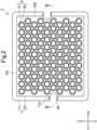
- Fig. 1 shows a package 1.
- the package 1 is used when being transported in a state where the syringe 2 is held.
- the package 1 includes the syringe 2, a syringe housing container 3, and a protection film 4.
- the package 1 is transported in an inverted posture which will be described later.
- the package 1 includes at least the protection film 4.
- the package 1 of the present embodiment includes the protection cover and the sterilization bag.
- the syringe body 20 is provided for storing and discharging a solution.
- the syringe body 20 has rigidity.
- the syringe body 20 is made of glass or a hard resin (for example, plastic), through which an inside can be viewed, for example.
- the syringe body 20 includes a trunk portion 200 which stores a solution, a holding portion 202 which holds the injection needle 204 for discharging a solution, and a periphery tube portion 203 which is formed in a periphery of the holding portion 202.
- the trunk portion 200 has a tubular shape.
- the trunk portion 200 includes one end and the other end in the axis direction Y in addition to an inner periphery surface and an outer periphery surface.
- the trunk portion 200 of the present embodiment has a cylindrical shape.
- the trunk portion 200 of the present embodiment has a constant length in the radial direction in each position in the axis direction Y.
- the inner periphery surface and the outer periphery surface extend in the axis direction Y.
- the one end (hereinafter referred to as a proximal end) of the trunk portion 200 in the axis direction Y is open.
- the other end (hereinafter referred to as a distal end) of the trunk portion 200 in the axis direction Y is closed except a portion for inserting the injection needle 204.
- the trunk portion 200 can be filled with a solution from the one side in the axis direction Y.
- the trunk portion 200 of the present embodiment has a drug solution filling portion (not numbered) as a portion to be filled with a drug solution as the solution.
- the drug solution filling portion denotes a portion, in the trunk portion 200, from a solution surface to a distal end of the filled drug solution.
- the trunk portion 200 is filled with the drug solution such that a length of the drug solution filling portion in the axis direction Y becomes shorter than a separation distance between the distal end of the trunk portion 200 and the flange portion 22 which will be described later.
- the holding portion 202 is provided at the distal end of the trunk portion 200.
- the holding portion 202 is configured to have a tubular shape which extends in the axis direction Y.
- An inside of the tubular holding portion 202 communicates with the portion for inserting the injection needle 204 at the distal end of the trunk portion 200, and the holding portion 202 thereby communicates with an inside of the tubular trunk portion 200.
- the holding portion 202 is shorter in the axis direction Y and has a diameter smaller than the trunk portion 200.
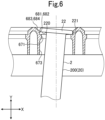
- the periphery tube portion 203 is formed into a cylindrical shape. An inner diameter of the periphery tube portion 203 is larger than an outer diameter of the holding portion 202. As shown in Fig. 5 , the periphery tube portion 203 is provided at the distal end of the trunk portion 200 so as to surround the holding portion 202 in the radial direction. An outer diameter of the periphery tube portion 203 of the present embodiment is smaller than an outer diameter of the trunk portion 200. Note that the periphery tube portion 203 is shorter than the holding portion 202 in the axis direction Y.
- the syringe body 20 has an abutting portion 201.
- the abutting portion 201 is a portion on the other side in the axis direction Y of the flange portion 22 which will be described later.
- the abutting portion 201 is a portion, in which the syringe 2 inserted through a tube portion 61 abuts a syringe abutting portion 671 when the syringe 2 moves in the tube portion 61, in the portion on the other side in the axis direction Y of the flange portion 22.
- the abutting portion 201 is a vicinity portion of the flange portion 22 in the outer periphery surface of the trunk portion 200.
- the abutting portion 201 is a region between the drug solution filling portion of the trunk portion 200 and the flange portion 22.
- the abutting portion 201 is arranged on the one side in the axis direction Y of the drug solution filling portion. Note that the abutting portion 201 is formed in a whole circumference of the outer periphery surface of the trunk portion 200.
- the injection needle 204 is inserted in the holding portion 202.
- the solution reserved in the syringe body 20 is discharged from the syringe body 20 via the injection needle 204 inserted in the holding portion 202 which communicates with the distal end of the trunk portion 200.
- the cap 21 is configured to have a bottomed tubular shape in which a distal end portion on the other side in the axis direction Y is closed.
- the cap 21 of the present embodiment is attached to the periphery tube portion 203 in a state where the cap 21 covers the injection needle 204 from the axis direction Y and the circumferential direction and thereby covers the distal end portion of the syringe body 20.
- the cap 21 is arranged on the distal end side of the syringe body 20 in the axis direction Y. Further, as shown in Figs.
- the cap 21 is configured to be larger than the syringe body 20 in the radial direction.
- a proximal end portion (not numbered) of the cap 21 is arranged on an outer side in the radial direction of the syringe body 20.
- the cap 21 is configured as a large-diameter portion (not numbered).
- the large-diameter portion is configured to have a diameter larger than the trunk portion 200.
- the large-diameter portion is arranged at the distal end of the trunk portion 200.
- the large-diameter portion is arranged on the other side in the axis direction Y of the abutting portion 201 as the vicinity portion of the flange portion 22.
- the cap 21 includes a tubular needle protection portion (not numbered) which covers the injection needle 204 from an outer diameter side and a cap body (not numbered) which protects at least the injection needle 204 from the other side in the axis direction Y.
- the cap body is attached to the needle protection portion.
- An outer diameter of the needle protection portion is larger than the outer diameter of the trunk portion 200.
- the needle protection portion is attached to the periphery tube portion 203 and is thereby arranged at the distal end of the trunk portion 200.
- the needle protection portion and the syringe body 20 move relative to each other in the axis direction Y, and thereby the needle protection portion is shifted from a state where the injection needle 204 is housed in the needle protection portion to a state where the injection needle 204 is protruded from the needle protection portion.
- the needle protection portion prevents the injection needle 204 from being unintentionally stuck into skin or the like of a person.
- the cap body is configured to have a bottomed tubular shape. An inner diameter of the cap body is larger than the outer diameter of the needle protection portion. In the present embodiment, in a state before use, the needle protection portion is inserted in the cap body. Accordingly, the injection needle 204 is prevented from protruding from the needle protection portion.
- the flange portion 22 protrudes from the outer periphery surface of the syringe body 20 to an outer side in the radial direction.
- the flange portion 22 has a diameter larger than the syringe body 20.
- the flange portion 22 of the present embodiment is provided in the radial direction. Further, the flange portion 22 is arranged on the proximal end side of the cap 21. The flange portion 22 of the present embodiment is provided at the proximal end of the trunk portion 200.
- the flange portion 22 is shorter than the syringe body 20 in the axis direction Y. As shown in Fig.
- the flange portion 22 includes a flange distal end portion 220 which is arranged on a distal end side, a flange edge portion 221 which is arranged on the one side in the axis direction Y of the flange distal end portion 220, and a flange proximal end portion (not numbered) which is arranged on a proximal end side.
- the flange portion 22 of the present embodiment is provided in a whole area in the circumferential direction.
- the flange distal end portion 220 and the flange proximal end portion are configured to have planar shapes which extend in the radial direction and the circumferential direction.
- the syringe housing container 3 includes a syringe holder 5 for holding the syringe 2 and a container body 8 which houses the syringe holder 5.
- the syringe holder 5 includes a holding body 6 and a periphery portion 7.
- the holding body 6 is a portion for holding the syringe 2.
- the holding body 6 includes a base plate portion 60 and the tube portions 61.
- the base plate portion 60 is formed into a plate shape (specifically, a flat plate shape).
- the base plate portion 60 shown in Figs. 1 and 3 is arranged in a state where a plate thickness direction coincides with the axis direction Y.
- the base plate portion 60 has a front surface 600 and a back surface 601.
- the base plate portion 60 of the present embodiment is a rectangular plate which extends in the vertical direction Z and the lateral direction X.
- the base plate portion 60 is configured to have short sides in the vertical direction Z and long sides in the lateral direction X.
- the tube portion 61 is a portion through which the syringe 2 is inserted.
- the tube portion 61 is configured to have a tubular shape (specifically, a cylindrical shape) having a diameter larger than the syringe 2.
- the tube portion 61 of the present embodiment is shorter than the syringe 2 in the axis direction Y.
- the tube portion 61 is arranged to pass through the base plate portion 60 in the plate thickness direction. That is, as shown in Fig. 3 , in a state where the axis direction Y is caused to coincide with the plate thickness direction of the base plate portion 60, the tube portion 61 of the present embodiment extends in the axis direction Y from one surface (specifically, the front surface 600) of the base plate portion 60 in the plate thickness direction and protrudes from the other surface (specifically, the back surface 601). Thus, a length of the tube portion 61 of the present embodiment in the axis direction Y is longer than a length of the base plate portion 60 in the plate thickness direction.
- a plurality of tube portions 61 are arranged in the base plate portion 60. Specifically, as shown in Figs. 2 and 3 , 10 tube portions 61 are arranged in the lateral direction X. Further, while the 10 tube portions 61 are set as one column, 10 columns are aligned in the vertical direction Z. Thus, 100 tube portions 61 are arranged in the base plate portion 60. Accordingly, the syringe holder 5 of the present embodiment is capable of holding a plurality of syringes 2. In the present embodiment, all of the tube portions 61 are in the same configuration. Thus, in the following, a description will be made about one tube portion 61 among the plurality of tube portions 61, and the description applies to the other tube portions 61.
- the column of the tube portions 61 which is positioned on the lowest side in the vertical direction Z in Fig. 2 is set as a first column and the columns are aligned, upward in the vertical direction Z, as a second column, a third column, ... in the vertical direction Z.
- the tube portion 61 positioned at a left end is arranged on a left side relative to the tube portion 61 positioned at a left end in the first column.
- the tube portion 61 at the left end of the second column is arranged on the left side from the tube portion 61 at the left end of the first column by half a distance, which corresponds to half a distance between centers of the tube portions 61 adjacent to each other in the lateral direction X.
- the tube portion 61 at the left end of each of even columns among the first to tenth columns is arranged on the left side by half the distance relative to the tube portion 61 at the left end of each of odd columns.
- the tube portion 61 at a right end of each of the odd columns is arranged on a right side by half the distance relative to the tube portion 61 at a right end of each of the even columns.
- the tube portions 61 in the columns adjacent to each other in the vertical direction Z are arranged in a staggered manner.
- hexagonal lattice arrangement is employed in which one tube portion 61 is surrounded by six tube portions 61.
- a separation distance from each of left and right tube portions 61 and 61, a separation distance from each of obliquely right and obliquely left tube portions 61 and 61 in the column higher by one column, and a separation distance from each of obliquely right and obliquely left tube portions 61 and 61 in the column lower by one column are equivalent.
- the tube portion 61 has a tubular shape.
- the tube portion 61 includes an outer wall surface 62 which constitutes an outer periphery surface, an inner wall surface 63 which constitutes an inner periphery surface, one end 64 which is arranged on the one side in the axis direction Y, and another end 65 which is continuous with the outer wall surface 62 and the inner wall surface 63 on the other side in the axis direction Y.
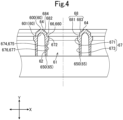
- the outer wall surface 62 forms the outer periphery surface of the tube portion 61. As shown in Figs. 3 and 4 , the outer wall surface 62 extends from the back surface 601 of the base plate portion 60 to the other side in the axis direction Y. The outer wall surface 62 is continuous with the back surface 601 of the base plate portion 60 and the other end 65.
- the outer wall surface 62 of the present embodiment is a tapered surface in which an outer diameter of the tube portion 61 becomes smaller toward the other side in the axis direction Y.
- the outer wall surface 62 extends in a circumferential direction of the tube portion 61.
- the outer wall surface 62 is a surface which extends in the axis direction Y and the circumferential direction. A length of the outer wall surface 62 of the present embodiment in the axis direction Y is longer than the length of the base plate portion 60 in the plate thickness direction.
- the inner wall surface 63 extends between the one end 64 and the other end 65 in the inner periphery surface of the tube portion 61.
- the inner wall surface 63 is longer than the outer wall surface 62 in the axis direction Y.
- the inner wall surface 63 (not provided with the reference numeral in Fig. 4 ) includes a flange support portion 66, a side wall portion 67 which is arranged on the other side in the axis direction Y relative to the flange support portion 66, and a rising wall portion 68 which is arranged on the one side in the axis direction Y relative to the flange support portion 66.
- the flange support portion 66 supports the flange portion 22 from the other side in the axis direction Y.
- the flange support portion 66 has a support surface 660 which extends in the radial direction.
- the support surface 660 of the present embodiment extends in the radial direction.
- the support surface 660 of the present embodiment extends in the circumferential direction.
- the support surface 660 of the present embodiment is a surface which extends in the radial direction and the circumferential direction.
- the support surface 660 of the present embodiment extends in a whole circumference in the circumferential direction.
- the flange support portion 66 is arranged throughout the whole circumference in the circumferential direction.
- the flange support portion 66 of the present embodiment is arranged on the other side in the axis direction Y relative to the back surface 601 of the base plate portion 60.
- the side wall portion 67 is formed on the other side in the axis direction Y relative to the flange support portion 66. As shown in Fig. 4 , the side wall portion 67 of the present embodiment is continuous with the flange support portion 66 and the other end 65. As shown in Fig. 5 , the side wall portion 67 is shorter than the syringe body 20 in the axis direction Y.
- the side wall portion 67 includes a syringe abutting portion 671 and a side wall body portion 673.
- the syringe abutting portion 671 abuts the syringe body 20 from an outer side in the radial direction.
- the syringe abutting portion 671 has a syringe abutting surface 672.
- the syringe abutting surface 672 of the present embodiment extends in the axis direction Y.
- the syringe abutting surface 672 extends in the circumferential direction.
- the syringe abutting surface 672 is a surface (specifically, a flat surface) which extends in the axis direction Y and the circumferential direction.
- the syringe abutting surface 672 of the present embodiment extends in the whole area in the circumferential direction. Accordingly, the syringe abutting portion 671 is arranged throughout the whole area in the circumferential direction. The syringe abutting portion 671 is arranged on an inner side in the radial direction relative to the flange support portion 66. As shown in Figs. 4 and 7 , in the present embodiment, the syringe abutting surface 672 is continuous from an end of the support surface 660 on a radially inner side, the support surface 660 extending in the radial direction, to the other side in the axis direction Y.
- the syringe abutting portion 671 is continuous with the flange support portion 66.
- An inner diameter of the syringe abutting portion 671 is shortest in the tube portion 61. As shown in Fig. 5 , the inner diameter of the syringe abutting portion 671 is larger than the cap 21. On the other hand, the inner diameter of the syringe abutting portion 671 is smaller than the flange portion 22.
- the side wall body portion 673 is arranged on the other side in the axis direction Y relative to the syringe abutting portion 671.
- the side wall body portion 673 of the present embodiment is arranged on a radially outer side relative to the syringe abutting portion 671. Further, the side wall body portion 673 of the present embodiment is longer than the syringe abutting portion 671 in the axis direction Y.
- the side wall body portion 673 includes a large-diameter guide portion 674 which guides the large-diameter portion (in the present embodiment, the cap 21) to an inner side in the radial direction and a side wall other-side portion 676.
- the large-diameter guide portion 674 is for guiding the large-diameter portion to the inner side in the radial direction when for example, in order to pull the syringe 2 from the tube portion 61, the syringe 2 inserted through the tube portion 61 is moved from the other side to the one side in the axis direction Y. As shown in Fig. 4 , the large-diameter guide portion 674 is configured to have a diameter decreasing from the other side toward the one side in the axis direction Y.
- the large-diameter guide portion 674 includes a large-diameter guide surface 675.
- the large-diameter guide surface 675 is an inclined surface in which an inner diameter of the tube portion 61 becomes smaller toward the one side in the axis direction Y.
- the large-diameter guide surface 675 extends in the circumferential direction.
- the large-diameter guide surface 675 is a surface which extends in directions, which intersect with the axis direction Y, and in the circumferential direction such that the inner diameter of the tube portion 61 becomes smaller toward the one side in the axis direction Y.
- the large-diameter guide surface 675 is continuous from an other-side end of the syringe abutting surface 672 in the axis direction Y to the other side in the axis direction Y.
- the large-diameter guide portion 674 and the syringe abutting portion 671 are continuous in the axis direction Y. Accordingly, the large-diameter guide portion 674 is arranged on the other side in the axis direction Y relative to the syringe abutting portion 671.
- the side wall other-side portion 676 is arranged on the other side in the axis direction Y and on the outer side in the radial direction, relative to the large-diameter guide portion 674.
- the side wall other-side portion 676 has a side wall other-side surface 677.
- the side wall other-side surface 677 is continuous with the large-diameter guide surface 675 and the other end 65.
- the side wall other-side surface 677 extends in the axis direction Y.
- the side wall other-side surface 677 of the present embodiment is an inclined surface in which the inner diameter of the tube portion 61 becomes larger toward the other side in the axis direction Y. Further, the side wall other-side surface 677 extends in the circumferential direction.
- the side wall other-side surface 677 is a surface which extends in the directions, which intersect with the axis direction Y, and in the circumferential direction such that the inner diameter of the tube portion 61 becomes larger toward the other side in the axis direction Y. Further, the side wall other-side surface 677 of the present embodiment is longer than the syringe abutting surface 672 in the axis direction Y.
- the rising wall portion 68 extends from the flange support portion 66 to the one end 64.
- the rising wall portion 68 of the present embodiment is shorter than the side wall portion 67 in the axis direction Y.
- the rising wall portion 68 includes a flange abutting portion 681 and a flange guide portion 683.
- the flange abutting portion 681 is arranged on the one side in the axis direction Y relative to the flange support portion 66. Further, the flange abutting portion 681 is arranged on the outer side in the radial direction relative to the flange support portion 66. As shown in Fig. 5 , the flange abutting portion 681 is capable of abutting, from the outer side in the radial direction, the flange portion 22 (specifically, the flange edge portion 221) which is supported by the flange support portion 66.
- the flange abutting portion 681 includes a flange abutting surface 682.
- the flange abutting surface 682 extends in the axis direction Y.
- the flange abutting surface 682 extends in the circumferential direction.
- the flange abutting surface 682 is a surface which extends in the axis direction Y and the circumferential direction.
- the flange abutting surface 682 is arranged in the whole area in the circumferential direction.
- the flange abutting portion 681 is arranged on the outer side in the radial direction relative to the flange support portion 66.
- the flange abutting surface 682 of the flange abutting portion 681 is continuous from an end of the support surface 660 on a radially outer side, the support surface 660 extending in the radial direction, to the one side in the axis direction Y.
- an inner diameter of the flange abutting portion 681 is larger than the inner diameter of the syringe abutting portion 671.
- the inner diameter of the flange abutting portion 681 is larger than the flange portion 22.
- a configuration is made such that a length of the flange abutting surface 682 in the axis direction Y is substantially the same as a length of the flange portion 22 in the axis direction Y.
- the flange guide portion 683 is arranged on the one side in the axis direction Y relative to the flange abutting portion 681. Further, the flange guide portion 683 is arranged on the outer side in the radial direction relative to the flange abutting portion 681.
- the flange guide portion 683 has a flange guide surface 684.
- the flange guide surface 684 is an inclined surface in which the inner diameter of the tube portion 61 becomes smaller toward the other side in the axis direction Y. Accordingly, the flange guide portion 683 is configured to have a diameter gradually decreasing from the one side toward the other side in the axis direction Y. Incidentally, as shown in Fig.
- lengths of the flange guide surface 684 and the support surface 660 in the radial direction are longer than a protruding length of the flange portion 22 with respect to the outer periphery surface of the syringe body 20.
- the flange guide surface 684 extends in the circumferential direction.
- the flange guide surface 684 is a surface which extends in the directions, which intersect with the axis direction Y, and in the circumferential direction such that the inner diameter of the tube portion 61 becomes smaller toward the other side in the axis direction Y.
- the flange guide surface 684 of the present embodiment extends in the whole area in the circumferential direction.
- the flange guide portion 683 is formed throughout the whole area in the circumferential direction.
- the flange guide surface 684 is continuous with the one end 64 and the flange abutting surface 682. Accordingly, an inner diameter of the flange guide portion 683 is larger than the inner diameter of the flange abutting portion 681. Note that the inner diameter of the flange guide portion 683 is larger than the flange portion 22.
- the one end 64 is a ridge portion between the rising wall portion 68 (specifically, the flange abutting surface 682) and the front surface 600 of the base plate portion 60.
- the one end 64 extends in the circumferential direction.
- an inner diameter of the one end 64 is largest in the tube portion 61.
- the other end 65 is continuous with the outer wall surface 62 and the side wall other-side portion 676 in the radial direction.
- the other end 65 has an other-end surface 650.
- the other-end surface 650 is a surface which extends in the radial direction and the circumferential direction.
- the other-end surface 650 of the present embodiment extends in the radial direction.
- the other end 65 of the present embodiment is arranged on the radially inner side relative to the one end 64.
- the periphery portion 7 is for raising the holding body 6 in the axis direction Y.
- the periphery portion 7 includes a step portion 70 and a placing portion 71.
- the step portion 70 is provided to extend from the base plate portion 60 to the other side in the axis direction Y.
- the step portion 70 is longer than the tube portion 61 in the axis direction Y.
- the step portion 70 of the present embodiment is provided in a whole area of the base plate portion 60 in the lateral direction X and the vertical direction Z.
- the step portion 70 includes a pair of vertical step portions 700 and 700 which are opposed to each other in the lateral direction X and a pair of lateral step portions 701 and 701 which are opposed to each other in the vertical direction Z.
- the pair of vertical step portions 700 and 700 are coupled with the pair of lateral step portions 701 and 701, and the step portion 70 is thereby formed throughout a whole area of the base plate portion 60 in the circumferential direction.
- the placing portion 71 is for placing the syringe holder 5 on the container body 8. As shown in Fig. 1 , the placing portion 71 is provided to extend from the step portion 70 to the other side in the axis direction Y. The placing portion 71 protrudes from the step portion 70 to the outer side in the radial direction. As shown in Fig. 2 , the placing portion 71 of the present embodiment is arranged in a whole area in the circumferential direction. The placing portion 71 has a front surface (not numbered) and a back surface (not numbered) in the plate thickness direction, and the back surface is placed on a side wall step portion 814 in the container body 8, which will be described later.
- a pair of cutouts 50 are formed in opposed sides.
- a finger or a hook is locked in a back surface of the syringe holder 5, and the cutouts 50 are thereby used when the syringe holder 5 is taken out from the container body 8.
- the cutouts 50 are formed which cutout the base plate portion 60 and the periphery portion 7.
- the placing portion 71 is provided with extension portions 710 which extend outward from the front surface.
- Each of the extension portions 710 extends outward from a peripheral edge of the cutout 50 formed in the front surface to the one side in the axis direction Y.
- the container body 8 is a container having a bottomed tubular shape.
- the container body 8 of the present embodiment includes a plate-shaped bottom portion 80 and a side wall portion 81 provided to extend from a peripheral edge of the bottom portion 80.
- the bottom portion 80 of the present embodiment is a rectangular plate-shaped member which has long sides and short sides.
- the side wall portion 81 includes a pair of width side wall portions 810 which are opposed to each other in a longitudinal direction of the bottom portion 80 (specifically, the lateral direction X) and a pair of longitudinal side wall portions 811 which are opposed to each other in a short-side direction of the bottom portion 80 (specifically, the vertical direction Z).
- Both end portions of the pair of width side wall portions 810 in the longitudinal direction are coupled with both end portions of the pair of longitudinal side wall portions 811 in the short-side direction. Accordingly, the side wall portion 81 is formed which is provided throughout the peripheral edge of the bottom portion 80.
- the side wall portion 81 has a lower-section side wall portion 812 which forms an opening region having substantially the same area as an area of the bottom portion 80 and an upper-section side wall portion 813 which forms an opening region wider than the opening region of the lower-section side wall portion 812.
- the lower-section side wall portion 812 is continuous with the peripheral edge of the bottom portion 80.
- An opening end edge of the upper-section side wall portion 813 serves as a brim portion 815 which is formed in a brim shape.
- the side wall portion 81 has a side wall step portion 814 for extending the opening region of the lower-section side wall portion 812 to the opening region of the upper-section side wall portion 813. Note that a length of the upper-section side wall portion 813 of the present embodiment in the axis direction Y is longer than a length of the syringe holder 5 in the axis direction Y.
- the protection film 4 is for tightly sealing an internal portion of the container body 8 by covering an opening of the container body 8.
- the protection film 4 is larger than the opening of the container body 8 in the lateral direction X and the vertical direction Z.
- the protection film 4 is used by being stuck to the brim portion 815 of the upper-section side wall portion 813.
- the protection film 4 of the present embodiment is stuck to the brim portion 815 by heat sealing.
- the protection film 4 is formed with a non-woven fabric which has gas permeability and microbe impermeability.
- the protection film 4 is configured such that sterilization gas is permeable.
- the protection film 4 is configured not to allow microbes or bacteria to enter the internal portion of the container body 8.
- the protection cover is for not allowing dirt to enter the inside of the trunk portion 200.
- the protection cover is used by covering the proximal end of the trunk portion 200. Note that the protection cover is made of a gas-permeable non-woven fabric through which sterilization gas is permeable.
- the sterilization bag is for housing the container body 8.
- the sterilization bag has gas permeability and microbe impermeability.
- the sterilization bag is configured such that sterilization gas is permeable. Further, the sterilization bag is configured not to allow microbes or bacteria to enter an inside of the sterilization bag.
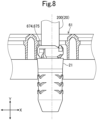
- the syringe 2 is inserted through the tube portion 61. Accordingly, the syringe 2 is held by the syringe holder 5. Specifically, as shown in Fig. 1 , in a state where the syringe 2 is arranged on the one side in the axis direction Y relative to the syringe holder 5, a distal end side of the syringe 2 is directed to the other side in the axis direction Y. Then, a central axis of the syringe 2 and a central axis of the tube portion 61 are caused to coincide with each other.
- the syringe 2 is inserted through the tube portion 61.
- the inner diameters of the flange guide portion 683 and the flange abutting portion 681 are larger than the flange portion 22.
- the syringe 2 can be inserted into the tube portion 61 from the one side in the axis direction Y.
- the flange guide surface 684 which is configured as the inclined surface in which the inner diameter of the tube portion 61 becomes smaller toward the other side in the axis direction Y
- the flange guide portion 683 have a diameter gradually decreasing from the one side toward the other side in the axis direction Y.
- the syringe 2 is easily inserted into the tube portion 61.
- the flange distal end portion 220 is placed on the support surface 660 from the other side of the flange distal end portion 220 in the axis direction Y. Accordingly, the flange portion 22 is supported by the flange support portion 66. Consequently, the syringe 2 is held by the syringe holder 5.
- the syringes 2 are inserted through all of the tube portions 61.
- the syringe holder 5 is arranged such that the lateral direction X of the syringe holder 5 holding the syringes 2 coincides with the longitudinal direction of the container body 8, and the back surface of the placing portion 71 is placed on the side wall step portion 814. Accordingly, the syringe holder 5 is housed in the container body 8.
- the length of the upper-section side wall portion 813 in the axis direction Y is longer than the length of the syringe holder 5 in the axis direction Y.
- the placing portion 71 is placed on the side wall step portion 814, and the syringe holder 5 is thereby housed in the container body 8. Further, in the present embodiment, in a state where the placing portion 71 is placed on the side wall step portion 814 and the syringe holder 5 is housed in the container body 8, a separation distance between the flange support portion 66 and the bottom portion 80 in the axis direction Y is longer than a length from the flange distal end portion 220 to the distal end of the syringe 2.
- the distal end of the syringe 2 is prevented from abutting the bottom portion 80, and the flange portion 22 can thereby be prevented from being separated from the flange support portion 66.
- the syringe 2 is covered by the protection cover. Specifically, in the container body 8, the protection cover is put on the front surface 600 of the base plate portion 60 and covers the syringes 2 inserted through all of the tube portions 61.
- the protection film 4 is stuck to the container body 8.
- the protection film 4 is stuck to the brim portion 815. Accordingly, the opening of the container body 8 is covered by the protection film 4, and the inside of the container body 8 is tightly sealed.
- the length of the upper-section side wall portion 813 in the axis direction Y is longer than the length of the syringe holder 5 in the axis direction Y.
- the protection film 4 when the protection film 4 is stuck, interference between the syringe holder 5 and the protection film 4 can be prevented.
- the container body 8 In a state where the internal portion of the container body 8 is tightly sealed, the container body 8, the syringe holder 5, the syringes 2, the protection cover, and the protection film 4 are arranged in this order from the other side to the one side in the axis direction Y.
- the container body 8 After the protection film 4 is stuck to the container body 8, the container body 8 is housed in the sterilization bag. Then, the sterilization bag which houses the container body 8 is tightly sealed. In such a manner, the package 1 is assembled. Further, in the present embodiment, the assembled package 1 is subjected to a sterilization treatment by a ⁇ ray for sterilization of microbes and bacteria.
- the sterilization bag, the protection film 4, and the protection cover have gas permeability.
- the sterilization treatment may be performed with sterilization gas. In this case, the sterilization gas permeates the sterilization bag, the protection film 4, and the protection cover, and an inside of the container body 8 is thereby sterilized.
- the syringe holder 5 of the present embodiment includes the plate-shaped base plate portion 60 and the tube portion 61 being formed into a tubular shape having the axis direction Y being provided along the plate thickness direction of the base plate portion 60, the tube portion 61 being configured to allow the syringe 2 to be inserted through the tube portion 61 from the one side toward the other side in the axis direction Y, the syringe 2 including the tubular syringe body 20 and the flange portion 22 protruding from the outer periphery surface of the syringe body 20 to the outer side in the radial direction.
- the tube portion 61 includes the inner wall surface 63 through which the syringe 2 is inserted, the flange support portion 66 having the support surface 660 which is positioned on the inner side of the inner wall surface 63 in the radial direction and extends in the radial direction, the flange support portion 66 being configured to abut the flange portion 22 of the inserted syringe 2 from the other side in the axis direction Y and supporting the flange portion 22 in the axis direction Y, and the flange abutting portion 681 being arranged on the one side in the axis direction Y relative to the flange support portion 66 and on the outer side in the radial direction relative to the support surface 660 and having the flange abutting surface 682 which extends in the axis direction Y, the flange abutting portion 681 being configured to abut the flange portion 22 supported by the flange support portion 66 from the outer side in the radial direction and to
- the flange support portion 66 supports the flange portion 22 of the syringe 2 from the other side in the axis direction Y, and the syringe 2 can thereby be supported.
- the flange abutting portion 681 which is arranged on the one side in the axis direction Y and on the outer side in the radial direction, relative to the flange support portion 66, abuts the flange portion 22 in the radial direction, movement of the syringe 2 in the radial direction can thereby be regulated, and displacement of the syringe 2 with respect to the tube portion 61 can thus be inhibited.
- the tube portion 61 includes the syringe abutting portion 671, and the syringe abutting portion 671 is arranged on the other side in the axis direction Y relative to the flange support portion 66 and on the inner side in the radial direction relative to the support surface 660 and has the syringe abutting surface 672 which extends in the axis direction Y, and the syringe abutting portion 671 is configured to be capable of abutting, from the outer side in the radial direction, a portion of the syringe body 20, the portion being in vicinity to the flange portion 22 in the syringe body 20 on the other side in the axis direction Y relative to the flange portion 22.
- the syringe abutting portion 671 which is arranged on the other side in the axis direction Y and on the inner side in the radial direction, relative to the flange support portion 66, is configured to be capable of abutting the portion of the syringe body 20, the portion being in vicinity to the flange portion 22 in the syringe body 20 on the other side in the axis direction Y relative to the flange portion 22.
- the syringe abutting portion 671 abuts the portion close to the flange portion 22 in the syringe body 20. Consequently, even if the syringe body 20 is scratched by abutting the syringe abutting portion 671, because a scratch is formed in the portion in vicinity to the flange portion 22, the scratch is formed in an inconspicuous part.
- the syringe body 20 includes the tubular trunk portion 200 which stores a solution
- the syringe 2 includes the large-diameter portion arranged in the distal end portion of the trunk portion 200 and configured to be larger than the trunk portion 200 in the radial direction
- the tube portion 61 includes the large-diameter guide portion 674 which guides the large-diameter portion to the inner side in the radial direction
- the large-diameter guide portion 674 is arranged on the other side in the axis direction Y relative to the syringe abutting portion 671 and is configured to have a diameter decreasing from the other side toward the one side in the axis direction Y.
- the large-diameter guide portion 674 which is arranged on the other side in the axis direction Y relative to the syringe abutting portion 671, is configured to have a diameter decreasing from the other side toward the one side in the axis direction Y.
- the tube portion 61 includes the flange guide portion 683 which guides the flange portion 22 to the inner side in the radial direction
- the flange guide portion 683 is arranged on the one side in the axis direction Y relative to the flange abutting portion 681 and on the outer side in the radial direction relative to the flange abutting surface 682 of the flange abutting portion 681
- has the flange guide surface 684 which extends in the axis direction Y, and is configured to have a diameter decreasing from the one side toward the other side in the axis direction Y.
- the flange guide portion 683 which is arranged on the one side in the axis direction Y and on the outer side in the radial direction, relative to the flange abutting portion 681, is configured to have a diameter decreasing from the one side toward the other side in the axis direction Y.
- the flange guide portion 683 which has a diameter gradually decreasing guides the flange portion 22 to the inner side in the radial direction, and the flange portion 22 can thereby be settled in the tube portion 61.
- the package 1 of the present embodiment includes the above-described syringe holder 5, the syringe 2, and the container body 8 which houses the syringe holder 5.
- the flange distal end portion 220 is placed on the support surface 660. Accordingly, the flange support portion 66 supports the flange portion 22 from the other side in the axis direction Y. Thus, the flange support portion 66 can support the syringe 2. Further, the flange abutting surface 682, which is continuous with the support surface 660, abuts the flange edge portion 221 from the outer side in the radial direction.
- the flange abutting portion 681 which is arranged on the one side in the axis direction Y and on the outer side in the radial direction, relative to the flange support portion 66, abuts the flange portion 22 in the radial direction.
- movement of the syringe 2 in the radial direction can be regulated.
- displacement of the syringe 2 with respect to the tube portion 61 can be inhibited.
- the flange abutting surface 682 is arranged in the whole area in the circumferential direction.
- the flange abutting portion 681 can abut the flange portion 22 in the radial direction.
- a gap between the flange abutting portion 681 and the flange edge portion 221 in the radial direction is smaller than a gap between the syringe body 20 (specifically, the trunk portion 200) and the side wall portion 67 in the radial direction.
- the flange abutting portion 681 first abuts the flange edge portion 221.
- the displacement of the syringe 2 with respect to the tube portion 61 can be inhibited, and the trunk portion 200 and the side wall portion 67 can also be inhibited from abutting each other.
- the outer periphery surface of the trunk portion 200 can be inhibited from being scratched.
- a gap between the side wall body portion 673 and the trunk portion 200 in the radial direction is larger than a gap between the syringe abutting portion 671 and the trunk portion 200 in the radial direction.
- the side wall body portion 673 arranged on the other side in the axis direction Y relative to the syringe abutting portion 671 is inhibited from abutting the trunk portion 200, and a scratch can thereby be inhibited from being formed on the distal end side of the trunk portion 200 (specifically, an outer periphery surface of the drug solution filling portion). Accordingly, by inhibiting a scratch from being formed on the outer periphery surface of the drug solution filling portion, the syringe 2 can be inhibited from being determined as a rejected product in a camera inspection for checking that no scratch or defect is present.
- the tube portion 61 includes the side wall portion 67 which is formed on the other side in the axis direction Y relative to the flange support portion 66.
- the side wall portion 67 includes the syringe abutting portion 671 which is continuous with the flange support portion 66 and the side wall body portion 673 which is formed on the other side in the axis direction Y relative to the syringe abutting portion 671.
- the syringe abutting portion 671 is arranged on the inner side in the radial direction relative to the flange support portion 66 and the side wall body portion 673 and is capable of abutting the syringe body 20.
- the syringe abutting portion 671 which is arranged on the inner side in the radial direction relative to the side wall body portion 673, abuts the abutting portion 201, in the syringe body 20, on the other side in the axis direction Y relative to the flange portion 22. Accordingly, even when the abutting portion 201 abuts the syringe abutting portion 671 and the outer periphery surface of the trunk portion 200 is scratched, a scratch is formed in the abutting portion 201. Consequently, the scratch is formed in an inconspicuous part.
- the syringe abutting surface 672 is a flat surface.
- a scratch is less likely to be formed in the abutting portion 201.
- the flange guide surface 684 which is continuous with the flange abutting surface 682 of the flange abutting portion 681, is the inclined surface in which the inner diameter of the tube portion 61 becomes smaller toward the other side in the axis direction Y.
- the flange guide portion 683 which has a diameter gradually decreasing from the one side to the other side in the axis direction Y, guides the flange portion 22 to the inner side in the radial direction. Accordingly, the flange portion 22 can be settled in the tube portion 61. That is, when the syringe 2 is advanced from the one side to the other side in the axis direction Y in the tube portion 61, the flange guide portion 683 guides the flange portion 22 to the inner side in the radial direction.
- the lengths of the flange guide surface 684 and the support surface 660 in the radial direction are longer than the protruding length of the flange portion 22 with respect to the outer periphery surface of the syringe body 20. Accordingly, even in a case where the flange portion 22 deviates to the one side in the axis direction Y and the syringe abutting portion 671 and the abutting portion 201 abut each other, the flange portion 22 is arranged on the radially inner side relative to the flange guide surface 684. Thus, the flange portion 22 can be prevented from running onto the front surface 600 of the base plate portion 60, and the flange portion 22 can be settled in the tube portion 61.
- the tube portion 61 extends from the front surface 600 of the base plate portion 60 in the axis direction Y (specifically, to the other side).
- an end portion of the tube portion 61 on the one side in the axis direction Y is connected to the base plate portion 60.
- a position of the end portion of the tube portion 61 on the one side in the axis direction Y is restrained by the base plate portion 60, and the end portion of each of the tube portions 61 on the one side in the axis direction Y can thereby be positioned.
- precision of positioning of the syringe 2 with respect to the tube portion 61 can be enhanced.
- the flange support portion 66 and the flange abutting portion 681 are arranged close to the one side of the tube portion 61 in the axis direction Y.
- positioning of the syringe 2 with respect to the tube portion 61 can highly precisely be performed.
- the step portion 70 is formed throughout the whole area of the base plate portion 60 in the circumferential direction.
- the step portion 70 supports the base plate portion 60 from the other side in the axis direction Y in the whole area in the circumferential direction. Accordingly, the base plate portion 60 can be prevented from being tilted.
- the container body 8 As described above, as shown in Fig. 5 , in a state where the package 1 is assembled, the container body 8, the syringe holder 5, the syringes 2, the protection cover, and the protection film 4 are arranged in this order from the other side to the one side in the axis direction Y. Further, the container body 8 is housed in the sterilization bag.
- the sterilization bag a state where, provided that the axis direction Y is set as a perpendicular direction, the container body 8, the syringe holder 5, the syringes 2, the protection cover, and the protection film 4 are arranged in this order from the other side (specifically, the lower side) to the one side (specifically, the upper side) will be referred to as an upright posture, and a state where the package 1 in the upright posture is inverted will be referred to as the inverted posture.
- the assembled package 1 is transported in the inverted posture. Specifically, a plurality of packages 1 are housed in a packing box in the inverted posture, and this packing box is transported.
- the transported package 1 is shifted from the inverted posture to the upright posture at a transportation destination. Then, at the transportation destination, the sterilization bag is unsealed, and the container body 8 is taken out. Then, the protection film 4 is peeled off from the container body 8 which is taken out, the protection cover is removed, and the syringe holder 5 holding the syringes 2 is taken out from the container body 8. Then, the syringe holder 5 holding the syringes 2 is set in a filling device, and the syringes 2 are filled with solutions by the filling device.
- the filling device two punching plates, each of which has a plurality of insertion holes in a plate thickness direction, are superimposed in a state where the respective insertion holes are aligned. Then, in a state where the distal end sides of the syringes 2 held by the syringe holder 5 are inserted through the insertion holes of the punching plates, the syringe holder 5 is placed on the punching plates.
- each of the tube portions 61 may extend in the axis direction Y from an other-side surface (specifically, the back surface 601) of the base plate portion 60 in the plate thickness direction and may protrude from a one-side surface (specifically, the front surface 600).
- the syringe holder 5 does not have to include the periphery portion 7.
- the side wall proximal end portion 678 has a side wall proximal end surface (not shown).
- the side wall proximal end surface extends in the axis direction Y and is continuous with the side wall other-side portion 676 and the other end 65. Further, the side wall proximal end surface extends in a whole area in the circumferential direction. Thus, the side wall proximal end surface extends in the axis direction Y and the circumferential direction. Further, an inner diameter of the side wall proximal end portion 678 is larger than an inner diameter of the side wall other-side portion 676. As shown in Figs.
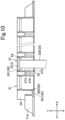
- the one end 64 is continuous with the outer wall surface 62 (not provided with the reference numeral in Fig. 10 ) and the rising wall portion 68 in the radial direction.
- the one end 64 has a one-end surface which extends in the radial direction and the circumferential direction.
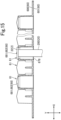
- a length of the flange abutting portion 681 in the axis direction Y may be longer than the length of the flange portion 22 in the axis direction Y. Accordingly, for example, the flange portion 22 can be inhibited from deviating from the tube portion 61 due to movement of the flange portion 22 supported by the flange support portion 66 to the one side in the axis direction Y.
- the length of the flange abutting portion 681 in the axis direction Y which is shown in Fig.
- the length of the flange abutting surface 682 of the flange abutting portion 681 in the axis direction Y may be longer than the length of the flange portion 22 in the axis direction Y. Accordingly, projection portions (not numbered) are formed in the tube portion 61. In Fig. 12 , at each predetermined angle (specifically, 120°), the length of the flange abutting surface 682 of the flange abutting portion 681 in the axis direction Y is longer than the length of the flange portion 22 in the axis direction Y.
- the length of the flange abutting surface 682 of the flange abutting portion 681 in the axis direction Y may be configured to be changed in the circumferential direction.
- the length of the flange abutting surface 682 of the flange abutting portion 681 in the axis direction Y is longest and is longer than the length of the flange portion 22 in the axis direction Y.
- the length of the flange abutting surface 682 in the axis direction Y gradually becomes shorter from the one part in the radial direction toward another side in the radial directions (specifically, a right side in Fig. 13 ). Furthermore, the length of the flange abutting surface 682 of the flange abutting portion 681 in the axis direction Y in another part 180° opposed to the one part in the radial directions (specifically, a right end of the cross section in Fig. 13 ) may be shorter than the length of the flange portion 22 in the axis direction Y.
- the length of the flange abutting surface 682 in the axis direction Y may be longest and longer than the length of the flange portion 22 in the axis direction Y in one part and another part in the radial directions. Further, in this case, the length of the flange abutting surface 682 in the axis direction Y may be configured to become shorter toward a radial outside, in a direction orthogonal to a diameter of the one part and the other part in the radial directions. Specifically, as shown in Fig. 15 , a configuration is made such that while the one part and the other part in the radial directions (not shown in Fig.
- the length of the flange abutting surface 682 in the axis direction Y becomes shorter toward the radial outside in the direction, which is orthogonal to the diameter of the one part and the other part in the radial directions, among the radial directions.
- the length of the flange abutting surface 682 in the axis direction Y in a direction which is, at the center of a circular shape, orthogonal to the diameter of the one part and the other part in the radial directions is shortest and shorter than the length of the flange portion 22 in the axis direction Y.
- the base plate portion 60 is configured to have a flat plate shape.
- the base plate portion 60 may be a curved plate.
- a description is made about a case where the base plate portion 60 is a rectangular plate.
- the base plate portion 60 may be a plate which has a circular shape in a plan view.
- the tube portion 61 has a cylindrical shape.
- the tube portion 61 may have a polygonal tubular shape.
- the cap 21 is configured to be larger than the syringe body 20 in the radial direction.
- the length of the cap 21 in the radial direction may be configured to be a length of the syringe body 20 in the radial direction or shorter.
- the tube portion 61 does not have to include the large-diameter guide portion 674.
- the tube portion 61 is shorter than the syringe 2 in the axis direction Y.
- this is not restrictive, and for example, the tube portion 61 may be longer than the syringe 2 in the axis direction Y.
- the syringe holder 5 is capable of holding one syringe 2.
- the length of the outer wall surface 62 in the axis direction Y is longer than the length of the base plate portion 60 in the plate thickness direction.
- this is not restrictive, and for example, the length of the outer wall surface 62 in the axis direction Y may be shorter than the length of the base plate portion 60 in the plate thickness direction.
- the support surface 660 is configured to extend in the radial direction.
- the support surface 660 may be configured as an inclined surface (for example, a curved surface or a flat surface) which extends to the one side or the other side in the axis direction Y toward the radially inner side.
- the support surface 660 may be an uneven surface.
- the support surface 660 is configured to extend in the whole circumference in the circumferential direction.
- the flange support portion 66 is arranged throughout the whole circumference in the circumferential direction.
- a plurality of flange support portions 66 may be arranged at predetermined intervals in the circumferential direction.
- the syringe abutting surface 672 of the syringe abutting portion 671 is formed in the whole circumference in the circumferential direction.
- the syringe abutting portion 671 is arranged throughout the whole area in the circumferential direction.
- this is not restrictive, and for example, a plurality of syringe abutting portions 671 may be arranged at predetermined intervals in the circumferential direction.
- the side wall portion 67 includes the syringe abutting portion 671 and the side wall body portion 673 which is arranged on the radially outer side relative to the syringe abutting portion 671.
- this is not restrictive, and for example, the side wall portion 67 does not have to include the side wall body portion 673.
- the syringe abutting portion 671 is continuous with the other end 65.
- the large-diameter guide surface 675 is continuous with the syringe abutting surface 672 of the syringe abutting portion 671, and the large-diameter guide portion 674 is thereby continuous with the syringe abutting portion 671 in the axis direction Y.
- this is not restrictive, and for example, the large-diameter guide portion 674 and the syringe abutting portion 671 may be arranged to be separated in the axis direction Y.
- the large-diameter guide surface 675 is the inclined surface in which the inner diameter of the tube portion 61 becomes smaller toward the one side in the axis direction Y.
- the "inclined surface” mentioned herein includes a curved surface which is curved to the radially inner side as it advances from the other side toward the one side in the axis direction Y and a flat surface.
- the large-diameter guide surface 675 may be configured as a curved surface in which a separation distance between the inner periphery surface and the outer periphery surface of the tube portion 61 in the radial direction becomes longer toward the one side in the axis direction Y.
- the large-diameter guide surface 675 may be configured as a curved surface in which the separation distance between the inner periphery surface and the outer periphery surface of the tube portion 61 in the radial direction becomes shorter toward the one side in the axis direction Y.
- the rising wall portion 68 is shorter than the side wall portion 67 in the axis direction Y.
- the rising wall portion 68 may be longer than the side wall portion 67 in the axis direction Y.
- the flange abutting surface 682 of the flange abutting portion 681 is configured to extend in the axis direction Y.
- the flange abutting surface 682 of the flange abutting portion 681 may be an inclined surface (specifically, a flat surface or a curved surface) in which the inner diameter of the tube portion 61 becomes smaller or larger toward the other side in the axis direction Y.
- the flange abutting surface 682 is continuous from the end of the support surface 660 on the radially outer side, the support surface 660 extending in the radial direction, to the one side in the axis direction Y. Accordingly, the flange support portion 66 is continuous with the flange abutting portion 681 in the axis direction Y.
- this is not restrictive, and the flange support portion 66 and the flange abutting portion 681 may be arranged to be separated in the axis direction Y.
- the flange guide surface 684 is continuous with the flange abutting surface 682.
- the flange guide portion 683 in the above embodiment is continuous with the flange abutting portion 681.
- the flange guide portion 683 may be arranged to be separated from the flange abutting portion 681 on the one side in the axis direction Y relative to the flange abutting portion 681.
- the flange guide portion 683 is formed throughout the whole area in the circumferential direction.
- this is not restrictive, and for example, a plurality of flange guide portions 683 may be arranged at predetermined intervals in the circumferential direction.
- the flange guide surface 684 is configured as the inclined surface in which the inner diameter of the tube portion 61 becomes smaller toward the other side in the axis direction Y.
- the "inclined surface” mentioned herein includes a curved surface which is curved to the radially inner side as it advances from the one side toward the other side in the axis direction Y and a flat surface.
- the flange guide surface 684 may be configured as a curved surface in which the separation distance between the inner periphery surface and the outer periphery surface of the tube portion 61 in the radial direction becomes longer toward the other side in the axis direction Y.
- the flange guide surface 684 may be configured as a curved surface in which the separation distance between the inner periphery surface and the outer periphery surface of the tube portion 61 in the radial direction becomes shorter toward the other side in the axis direction Y.
- the trunk portion 200 has the drug solution filling portion as the portion to be filled with a drug solution.
- a scale (not shown) for checking a filled solution amount may be provided by printing.
- the abutting portion 201 is an area between the scale provided on the outer periphery surface of the trunk portion 200 and the flange portion 22.
- the outer periphery surface on the distal end side relative to the abutting portion 201 (specifically, the drug solution filling portion) in the outer periphery surface of the trunk portion 200 is prevented from being scratched, and a situation can thereby be prevented where the printed scale is peeled off and cannot be read.
- the large-diameter portion is arranged on the other side in the axis direction Y relative to the scale.
- the outer diameter of the periphery tube portion 203 is smaller than the outer diameter of the trunk portion 200.
- the outer diameter of the periphery tube portion 203 may be configured to be larger than the outer diameter of the trunk portion 200.
- the periphery tube portion 203 may be configured as the large-diameter portion.
Landscapes
- Health & Medical Sciences (AREA)
- Veterinary Medicine (AREA)
- Life Sciences & Earth Sciences (AREA)
- Engineering & Computer Science (AREA)
- General Health & Medical Sciences (AREA)
- Public Health (AREA)
- Animal Behavior & Ethology (AREA)
- Heart & Thoracic Surgery (AREA)
- Hematology (AREA)
- Biomedical Technology (AREA)
- Anesthesiology (AREA)
- Vascular Medicine (AREA)
- Mechanical Engineering (AREA)
- Diabetes (AREA)
- Pharmacology & Pharmacy (AREA)
- Infusion, Injection, And Reservoir Apparatuses (AREA)
- Medical Preparation Storing Or Oral Administration Devices (AREA)
- Packaging Of Annular Or Rod-Shaped Articles, Wearing Apparel, Cassettes, Or The Like (AREA)
- Buffer Packaging (AREA)
Applications Claiming Priority (2)
| Application Number | Priority Date | Filing Date | Title |
|---|---|---|---|
| JP2022110458A JP2024008521A (ja) | 2022-07-08 | 2022-07-08 | シリンジ保持具、包装体 |
| PCT/JP2023/024859 WO2024010018A1 (ja) | 2022-07-08 | 2023-07-05 | シリンジ保持具、包装体 |
Publications (2)
| Publication Number | Publication Date |
|---|---|
| EP4523720A1 true EP4523720A1 (de) | 2025-03-19 |
| EP4523720A4 EP4523720A4 (de) | 2026-04-29 |
Family
ID=89453467
Family Applications (1)
| Application Number | Title | Priority Date | Filing Date |
|---|---|---|---|
| EP23835549.9A Pending EP4523720A4 (de) | 2022-07-08 | 2023-07-05 | Spritzenhalter und verpackung |
Country Status (6)
| Country | Link |
|---|---|
| US (1) | US20250375567A1 (de) |
| EP (1) | EP4523720A4 (de) |
| JP (1) | JP2024008521A (de) |
| KR (1) | KR20250034018A (de) |
| CN (1) | CN119317461A (de) |
| WO (1) | WO2024010018A1 (de) |
Families Citing this family (1)
| Publication number | Priority date | Publication date | Assignee | Title |
|---|---|---|---|---|
| CN119329889A (zh) * | 2024-10-31 | 2025-01-21 | 江苏乐聚医药科技有限公司 | 一种巢板 |
Family Cites Families (6)
| Publication number | Priority date | Publication date | Assignee | Title |
|---|---|---|---|---|
| WO2004082745A1 (fr) * | 2003-02-24 | 2004-09-30 | Becton Dickinson France | Plateau pour le groupage d'objets de corps de seringue |
| GB201004102D0 (en) * | 2010-03-12 | 2010-04-28 | Liversidge Barry P | Syringe barrels and handling systems |
| WO2014049713A1 (ja) * | 2012-09-26 | 2014-04-03 | テルモ株式会社 | 注射筒収納容器 |
| WO2014049712A1 (ja) | 2012-09-26 | 2014-04-03 | テルモ株式会社 | 注射筒収納容器 |
| WO2014102987A1 (ja) * | 2012-12-27 | 2014-07-03 | テルモ株式会社 | プレフィルドシリンジ用外筒およびプレフィルドシリンジ用外筒包装体 |
| IT201800003376A1 (it) * | 2018-03-08 | 2019-09-08 | Nuova Ompi Srl | Struttura per il confezionamento di contenitori ad uso farmaceutico |
-
2022
- 2022-07-08 JP JP2022110458A patent/JP2024008521A/ja active Pending
-
2023
- 2023-07-05 US US18/877,181 patent/US20250375567A1/en active Pending
- 2023-07-05 CN CN202380047589.8A patent/CN119317461A/zh active Pending
- 2023-07-05 EP EP23835549.9A patent/EP4523720A4/de active Pending
- 2023-07-05 KR KR1020247038191A patent/KR20250034018A/ko active Pending
- 2023-07-05 WO PCT/JP2023/024859 patent/WO2024010018A1/ja not_active Ceased
Also Published As
| Publication number | Publication date |
|---|---|
| EP4523720A4 (de) | 2026-04-29 |
| KR20250034018A (ko) | 2025-03-10 |
| WO2024010018A1 (ja) | 2024-01-11 |
| JP2024008521A (ja) | 2024-01-19 |
| CN119317461A (zh) | 2025-01-14 |
| US20250375567A1 (en) | 2025-12-11 |
Similar Documents
| Publication | Publication Date | Title |
|---|---|---|
| KR102452207B1 (ko) | 컨테이너 | |
| US10507280B2 (en) | Medical instrument housing container | |
| ES2684524T3 (es) | Bandeja y embalaje para contenedores médicos | |
| EP3345587B1 (de) | Behälterhalteelement und satz aus medizinischen behältern | |
| US9623171B2 (en) | Medical device package | |
| EP2331166B1 (de) | Verschluss für behälter | |
| EP3524293A1 (de) | Halteelement und verpackungsstruktur von chemischen behälterteilen | |
| ES2974927T3 (es) | Dispositivo de envasado configurado para soportar contenedores médicos y método para extraer los contenedores médicos de dicho dispositivo de envasado | |
| ES3042538T3 (en) | Container for packaging units | |
| EP3691715B1 (de) | Verpackungsvorrichtung und verfahren zum entfernen medizinischer behälter aus der verpackungsvorrichtung | |
| EP4523720A1 (de) | Spritzenhalter und verpackung | |
| EP3871705B1 (de) | Gehäuse für medizinische vorrichtung | |
| WO2014049714A1 (ja) | 注射筒収納容器 | |
| WO2013129278A1 (ja) | シリンジ収納容器及びシリンジ梱包体 | |
| US11751969B2 (en) | Storage container, packaging member, and medical instrument set | |
| WO2014049715A1 (ja) | 注射筒収納容器 | |
| EP4603115A1 (de) | Behältersystem für medizinische komponenten mit entgasungsventil | |
| KR20260002310A (ko) | 반송용 용기 | |
| WO2024224666A1 (ja) | 搬送用容器 |
Legal Events
| Date | Code | Title | Description |
|---|---|---|---|
| STAA | Information on the status of an ep patent application or granted ep patent |
Free format text: STATUS: THE INTERNATIONAL PUBLICATION HAS BEEN MADE |
|
| PUAI | Public reference made under article 153(3) epc to a published international application that has entered the european phase |
Free format text: ORIGINAL CODE: 0009012 |
|
| STAA | Information on the status of an ep patent application or granted ep patent |
Free format text: STATUS: REQUEST FOR EXAMINATION WAS MADE |
|
| 17P | Request for examination filed |
Effective date: 20241212 |
|
| AK | Designated contracting states |
Kind code of ref document: A1 Designated state(s): AL AT BE BG CH CY CZ DE DK EE ES FI FR GB GR HR HU IE IS IT LI LT LU LV MC ME MK MT NL NO PL PT RO RS SE SI SK SM TR |
|
| DAV | Request for validation of the european patent (deleted) | ||
| DAX | Request for extension of the european patent (deleted) |