EP3402622B1 - Vorrichtung zum giessen - Google Patents
Vorrichtung zum giessen Download PDFInfo
- Publication number
- EP3402622B1 EP3402622B1 EP17700931.3A EP17700931A EP3402622B1 EP 3402622 B1 EP3402622 B1 EP 3402622B1 EP 17700931 A EP17700931 A EP 17700931A EP 3402622 B1 EP3402622 B1 EP 3402622B1
- Authority
- EP
- European Patent Office
- Prior art keywords
- mold
- permanent mold
- casting
- furnace
- melting charge
- Prior art date
- Legal status (The legal status is an assumption and is not a legal conclusion. Google has not performed a legal analysis and makes no representation as to the accuracy of the status listed.)
- Not-in-force
Links
Images


Classifications
-
- B—PERFORMING OPERATIONS; TRANSPORTING
- B22—CASTING; POWDER METALLURGY
- B22D—CASTING OF METALS; CASTING OF OTHER SUBSTANCES BY THE SAME PROCESSES OR DEVICES
- B22D18/00—Pressure casting; Vacuum casting
- B22D18/04—Low pressure casting, i.e. making use of pressures up to a few bars to fill the mould
-
- B—PERFORMING OPERATIONS; TRANSPORTING
- B22—CASTING; POWDER METALLURGY
- B22D—CASTING OF METALS; CASTING OF OTHER SUBSTANCES BY THE SAME PROCESSES OR DEVICES
- B22D23/00—Casting processes not provided for in groups B22D1/00 - B22D21/00
- B22D23/006—Casting by filling the mould through rotation of the mould together with a molten metal holding recipient, about a common axis
-
- B—PERFORMING OPERATIONS; TRANSPORTING
- B22—CASTING; POWDER METALLURGY
- B22D—CASTING OF METALS; CASTING OF OTHER SUBSTANCES BY THE SAME PROCESSES OR DEVICES
- B22D35/00—Equipment for conveying molten metal into beds or moulds
-
- B—PERFORMING OPERATIONS; TRANSPORTING
- B22—CASTING; POWDER METALLURGY
- B22D—CASTING OF METALS; CASTING OF OTHER SUBSTANCES BY THE SAME PROCESSES OR DEVICES
- B22D39/00—Equipment for supplying molten metal in rations
- B22D39/02—Equipment for supplying molten metal in rations having means for controlling the amount of molten metal by volume
- B22D39/026—Equipment for supplying molten metal in rations having means for controlling the amount of molten metal by volume using a ladler
Definitions
- the present invention relates to a device for casting metal bodies, in particular by a chill casting process.
- Chill casting devices are well known.
- a mold delimits a mold cavity. Liquid metal is introduced into the mold cavity and hardens in the mold cavity. When removing the mold, the cured piece of metal is removed from the mold.
- a permanent mold with two mold halves is often used, which is arranged in a vertical press.
- the two halves of the mold are pressed together with the press.
- the liquid metal melt is introduced into the mold from below at low pressure.
- a press with a sliding table can be used for simple demolding.
- the sliding table has a horizontally displaceable frame on which a mold half of the mold is arranged. To remove the mold, the other half of the mold is lifted and the frame is moved out of the area of the press so that the cast part can be easily removed.
- a low pressure chill casting machine comprising a melting furnace and a stratified loading container, with a support column rotatable about its vertical axis being arranged between these two.
- a support frame is attached to the support column and has a guide in which a bearing head is vertically displaceable.
- the support column In the bearing head is a relative to a horizontal one the support column is mounted on the radial axis, pivotable T-shaped support frame.
- Two holders are mounted on a crossbeam of the support frame. On the one hand, the holders can be displaced in a longitudinal axis of the crossbeam and, on the other hand, they can be pivoted about this longitudinal axis.
- a support arm is mounted, to each of which one half of a mold is attached.
- the support arms are rotatable about their own longitudinal axis and also pivotable about axes perpendicular to their axis of rotation and to the longitudinal axis of the holder.
- the mold halves into any position and, moreover, to cast them in a parting plane.
- it should be possible to remove a casting since the molds can be rotated in such a way that a casting spigot is directed forwards, which enables easy gripping using conventional pliers. Because the mold and also a riser pipe can be held by means of the device, it is possible that the sprue pin does not have to be torn off even if a parting line runs vertically.
- a quick-change frame for die casting machines.
- Such a quick-change frame comprises guide rails which are designed to be tiltable by 90 degrees relative to the horizontal. Furthermore, the quick-change frame can be removed from a tilting mold casting machine, so that after casting, another quick-change frame, in which a mold already heated to operating temperature is clamped, can be inserted into the guide rails that are still lowered.
- the quick-change frame it should be possible to reduce the space required by a chill casting machine, since it is no longer necessary for an entire casting device to be tilted upwards.
- faster processing should be possible through the use of several quick-change frames with appropriately preheated molds.
- This low-pressure chill casting system comprises a first furnace and a second furnace as well as two handling units which are alternately assigned to the furnaces.
- a station for unloading the cast parts and performing graphitization of the casting mold is provided between the furnaces. This station should make it possible to use the furnaces with independent operating pressures and metal fill levels.
- the handling units are provided with a removal unit for removing the cast part, the removal unit being provided for moving the cast part towards an operator and for rotating the cast part about a horizontal axis.
- a filling device comprises a furnace which has an electromagnetic pump in order to introduce liquid metal from the furnace via inlets into a corresponding cavity of a casting mold. It is provided that the casting mold is arranged in a frame that can be tilted about a pivot axis. In addition, a feed device connected to the casting mold via two channels is arranged in the frame. The feed device comprises a feed channel which can be connected to an electromagnetic pump of the filling device. In this way it should be possible, when filling a mold at low pressure by means of the electromagnetic pump, to raise and lower the mold or to tilt it during the filling process.
- This device and this method thus relate to the inclination of a casting mold when filling a casting mold by means of an electromagnetic pump according to the low-pressure casting process.
- This device is preferably designed for casting under pressure, in particular as a counter-pressure chill casting system or a low-pressure chill casting system.
- the casting device comprises a lower hermetically sealable chamber and an upper hermetically sealable chamber, which are separated from one another by a platen.
- a furnace is provided in the lower chamber, which has a crucible with melt.
- a two-part casting mold is arranged in the upper chamber, which has a lower casting mold half and an upper casting mold half.
- the crucible is connected to the casting mold via a riser pipe.
- the upper mold half can be pivoted out of the device about a horizontal pivot axis.
- a casting mold half is intended to be pivoted into a position after the permanent casting mold has been opened so that an inner surface of the casting mold half can be treated, preferably cleaned, smoothed and / or corrected by a person in a work-saving and time-saving manner. This is especially intended as preparation for a new casting cycle.
- CN 105215338 A discloses a lifting device for lifting a furnace.
- the document discloses an apparatus for low pressure casting, wherein a furnace can be connected to a casting mold via three riser pipes and this furnace has a lifting or lowering mechanism.
- the invention is based on the object of creating a device for casting according to the permanent mold casting process, with which different casting processes can be carried out.
- a mold arranged in the holding element is moved from one location, preferably in the horizontal direction, to another Movable location.
- a mold arranged in the holding element is moved from one location, preferably in the horizontal direction, to another Movable location.
- DE 30 06 785 C2 described device provided in order to rotate, turn, lift and thus move a mold in all directions.
- pivoting is provided for carrying out a regulated casting process, in contrast to that in FIG DE 44 34 258 A1 disclosed device in which it should be possible by pivoting the quick-change frame to pull the quick-change frame out of the guide rails by means of a crane hook.
- the device according to the invention for casting cast parts comprises at least one pivotable, preferably horizontally displaceable, holding element for receiving a mold, a melting furnace, which can be connected to a low-pressure mold by means of a melt line in such a way that melt can be fed to the low-pressure mold according to the low-pressure process and for performing mold casting processes a melt feed device with which melt can be fed to a gravity mold located on the holding element.
- a combined device is provided with which, on the one hand, a melt can be fed directly to a low-pressure mold from the melting furnace by means of the melting line and, on the other hand, melt can be removed from the melting furnace and fed to the gravity mold by means of, for example, one of the scooping devices.
- the permanent mold casting process is a casting process in which a melt is poured into a permanent metal mold called a permanent mold via an overhead sprue and the cavity fills the cavity solely as a result of gravity.
- mold casting processes are understood to mean, for example, drop casting, gravity casting, tilting crucible casting (by level shifting) and low-pressure casting.
- the casting device preferably has a control device which is designed to pivot the holding element for evenly distributing the melt in the gravity mold.
- the horizontally displaceable and pivotable holding element can be a holding frame, as is known from conventional sliding and tilting tables.
- the melt supply device with which melt can be fed to a gravity mold, which is located on the holding element, it is possible to distribute the melt in a gravity mold evenly in the mold cavity of the gravity mold by pivoting the holding element and thus rotating the gravity mold.
- the holding element is preferably designed such that it can be pivoted or rotated from a horizontal position to an inclined position by an angle of at least 45 °, preferably at least 90 °, in particular at least 180 ° and preferably 360 °.
- the holding element preferably has holding devices, such as. B. clamps or bolts with which the gravity mold can be fixed on the holding element so that it is firmly connected to the holding element even in an inclined position.
- holding devices such as. B. clamps or bolts with which the gravity mold can be fixed on the holding element so that it is firmly connected to the holding element even in an inclined position.
- a pivotably mounted tilting plate can be provided for pivoting the mold.
- the holding element is a holding frame that is preferably displaceable on the tilting plate.
- the furnace is preferably a combined low-pressure / scoop furnace, so that, on the one hand, a melt can be fed from the melting furnace by means of a melt line directly to a low-pressure mold or a gravity mold, preferably by a low-pressure control, and, on the other hand, melt can be removed from the melting furnace and fed to the gravity mold by means of a scoop device.
- a commercially available robot can be provided as the scooping device.
- a scoop line or metering line can also be provided, with which melt can be fed from the furnace to the gravity mold by applying low pressure.
- a lifting device is preferably provided for lifting the furnace.
- the top of the furnace can be arranged directly below a base plate which carries the mold. As a result, the height difference between the mold and the melting furnace can be reduced.
- two furnaces can also be provided, one serving to supply the low-pressure mold with melt and the other to supply the gravity mold with melt.
- the gravity mold For receiving the melt, the gravity mold has a pouring pool, which is an upwardly open section of the ingot mold, the melt flowing from the pouring pool into the mold cavity of the ingot mold by rotating the ingot mold about a predetermined axis of rotation.
- the casting device preferably has a press, in particular a column press.
- Such a column press can be formed from a stationary base plate, a stationary upper frame and a movable clamping plate, with columns being arranged in each case at the corner areas of the plates and at the corner areas of the upper frame.
- the pillars are usually stationary.
- two front columns are designed to be vertically movable, as is the case in the German patent application DE 10 2015 119 243.8 is described. Reference is therefore made to the full content of this patent application.
- the press preferably has a lifting mechanism on the upper frame with which the movable platen can be moved in the vertical direction.
- the press is primarily intended for pressing two mold halves of a low-pressure mold together so that melt can be fed to the low-pressure mold under pressure.
- the upper mold half of the low-pressure mold can be fixed to the movable platen so that the mold can be opened by lifting the platen and thus lifting the upper mold half of the mold by means of the movable platen after the casting process.
- the gravity mold can be designed in one or more parts. If the gravity mold is constructed in several parts, the individual parts are fastened to one another during the casting process by means of clamps, bolts or other suitable fixing devices. For demolding, the several parts of the gravity mold can be separated from one another.
- One embodiment of a casting device 1 has a horizontally arranged base plate 2, an upper frame 3 and a movable clamping plate 4 arranged between them. At the corner areas of the plates 2, 4 and the upper frame 3, columns 5 are provided, which basically extend from the base plate 2 to the upper frame 3 and keep them at a distance.
- the base plate 2, the upper frame 3 and the movable platen 4 are arranged parallel to one another.
- the columns 5 extend through corresponding through openings in the movable platen 4 and serve to guide the movable platen 4 so that the movable platen 4 is always arranged parallel to the base plate 2 and to the upper frame 3.
- the base plate 2 and the movable platen 4 are designed as plate-shaped elements. However, they can also be designed as a frame-shaped frame.
- the upper frame 3 is designed as a frame-shaped frame in the exemplary embodiment. However, it can also be a plate-shaped element.
- a lifting mechanism 6 is arranged on the upper frame 3.
- the lifting mechanism is a hydraulic cylinder.
- the lifting mechanism 6 is coupled with a lifting rod 7 to the movable platen 4 and can adjust it in the vertical direction. It can also be useful to have several lifting mechanisms to be provided for moving the movable platen 4.
- the lifting mechanism 6 is arranged centrally on the upper frame 3. If several lifting mechanisms are provided, then these can be arranged on the edge regions of the upper frame 3.
- Rails 8 are provided on the base plate 2 and extend from a rear edge of the base plate 2 over a front edge of the base plate 2.
- the rails 8 serve to guide a holding frame 9 which is coupled to the rails 8 by means of a coupling element 10.
- the coupling element 10 is used to move the holding frame 9 in the longitudinal direction of the rails 8 and also to rotate or pivot the holding frame 9.
- the part of the casting device 1 described so far thus forms a column press with a sliding / tilting table.
- a furnace 11 is provided in the area below the base plate 2.
- the furnace 11 has a melt line 12, which is passed up through the base plate 2 and is designed for coupling a low-pressure mold 13.
- the low-pressure mold 13 is formed from a lower mold half 14 and an upper mold half 15.
- the lower mold half 14 is arranged on the holding frame 9.
- the upper mold half 15 is acted upon by the clamping plate 4, so that the lower mold half 14 and the upper mold half 15 are firmly pressed together.
- the upper mold half 15 is preferably releasably attached to the movable platen 4.
- the in Figure 1 In the state shown, melt can be fed from the melting furnace 11 to the low-pressure mold 13 via the melt line 12 in accordance with the low-pressure method.
- the clamping plate 4 and thus also the upper mold half 15 are raised. This opens the low-pressure mold 13.
- the lower mold half 14 of the low-pressure mold is moved by means of the horizontally displaceable holding frame 9 over the front edge of the base plate 2.
- the holding frame 9 is tilted a little so that an operator can simply take the cast part out of the lower mold half 14.
- the cast part can also be removed using a robot. However, the table does not have to be tilted for removal.
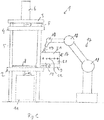
- a gravity mold 16 can also be arranged on the holding frame 9.
- the gravity mold 16 can in its upper Area have a pouring pool (not shown), which is an upwardly open, trough-shaped or channel-shaped element.
- the pouring pool can be filled with melt.
- a robot 17 is provided in the present exemplary embodiment, which is designed with several joints 18. The robot 17 has a free end to which a ladle 19 is attached.
- the robot can remove melt from the furnace 11 and pour it into the pouring pool of the gravity mold 16.
- the holding frame 9 is optionally arranged horizontally or vertically or at a different angle so that the pouring pool is open at the top.
- the gravity mold is preferably fastened to the holding frame 9 with corresponding fastening elements, so that the gravity mold 16 is securely held on the holding frame even during a pivoting process.
- the mold can be rotated by up to 360 °, preferably about 180 °, by means of the rotatable table.
- the gravity mold 16 is removed from the mold. It can be swiveled into a suitable swivel position for removal from the mold.
- the gravity mold 16 is formed from a lower mold half 20 and an upper mold half 21, which are held together with clamps 22. To remove the mold, the clamps 22 are released and the two mold halves 20, 21 are separated from one another. The casting can then be removed from the lower mold half.
- the robot 17 can be provided with a changing device at its free end, so that different tools such as ladles, gripping devices or the like can be attached to the robot 17. With such a gripping device, the casting can also be automatically removed from the lower mold half 14 of the low-pressure mold 13 or the lower mold half 20 of the gravity mold 16 by means of the robot.
- the robot 17 serves as a melt supply device for supplying melt to the gravity mold.
- melt supply devices such as. B. a melt line or low pressure line, which ends in the area above the pouring pool of the gravity mold, may be provided.
- melt feed device and pivotable holding frame 9, which serves as a holding element for the molds, it is possible to carry out a low-pressure casting process with a low-pressure mold and a gravity casting process with a gravity mold in a casting device.
- the holding frame 9 is not necessarily designed to be horizontally displaceable. In principle, it is also possible to arrange the gravity mold at the same location as the low-pressure mold during the casting process. However, it is advantageous if the holding frame or the holding element is horizontally displaceable, since this simplifies the arrangement of the melting furnace and the melting line.
- Figure 4 shows a further embodiment of a casting device 1 according to the invention, which in turn comprises a base plate 2, an upper frame 3, a movable clamping plate 4, columns 5 which extend between the base plate 2 and the upper frame 3.
- a furnace 11 is again provided underneath the base plate 2 and, in this exemplary embodiment, the clamping plate 4 is provided by means of two lifting mechanisms 6, which are designed as hydraulic cylinders for actuating a lifting rod 7 in each case.
- a holding frame 9 is arranged horizontally displaceably on rails 8, so that the holding frame can be located on the base plate 2 in the area within the columns 5.
- the present exemplary embodiment differs from the exemplary embodiment explained above in that a tilting table 23 is fastened to the base plate 2, which tilting table has a tilting plate 24 which is designed independently of the holding frame 9.
- the tilting table 23 comprises two stable holding arms 25, which extend from the front edge of the base plate 2 in a slightly inclined manner towards the front.
- a pivot joint 26 is provided, with which the tilting plate 24 is pivotably mounted on the holding arms 25.
- a swivel motor 27 is arranged on one of the two holding arms 25, with which the tilting plate 24 can be actuated for swiveling about a horizontal axis.
- the surface of the tilting plate 24 is aligned with the surface of the base plate 2.
- mutually aligned rail sections 8 are provided so that the holding frame 9 in the horizontal position of the tilting plate 24 on the rails 8 can be moved back and forth between the tilting plate 24 and the base plate 2.
- the holding frame 9 is moved by means of hydraulic piston / cylinder units (not shown).
- the movable platen 4 is not guided on the columns 5, Instead, a separate guide mechanism 28 is provided which comprises four guide rods 29, each of which is fastened with one end in the region of a corner of the clamping plate 4 and with the other end on a guide frame 30.
- the guide rods 29 each extend through a through opening on the upper frame 3, sliding bushings 31 being provided here for guiding the guide rods 29 on the upper frame 3.
- the guide mechanism 28 can be moved by the two hydraulic lifting mechanisms 6 or can be held in its respective vertical position.
- a base plate 32 is provided below the base plate 2, on which the furnace 11 is located.
- the base plate 2 is held at a distance from the base plate 32 by means of four floor columns 33.
- the floor pillars 33 are formed independently of the pillars 5.
- the melting furnace 11 is mounted displaceably on rollers 34, so that the melting furnace 11 can be moved out of the area between the base plate 32 and the base plate 2 and retracted again.
- the furnace 11 is arranged on a lifting device (not shown) with which the furnace 11 can be raised a little.
- the lifting path is designed in such a way that the upper side of the furnace 11 in the raised position is located at a small distance directly below the base plate 2.
- This casting device 1 in turn has a robot that is shown in FIG Figure 4 is omitted for simpler graphic representation.
- Figure 4 also shows no mold and no melt line.
- a low-pressure casting process can be carried out with a low-pressure mold and a gravity casting process can be carried out with a gravity mold.
- the gravity mold is preferably always arranged outside the area of the base plate or the area above the melting furnace 11, so that the gravity mold does not have to be moved linearly after being filled with melt, but is merely pivoted.
- a linear movement would, on the one hand, delay the start of the pivoting process, as a result of which the melt can already be partially cured, and, due to the melt moving in the mold, it can lead to contamination of the melt, which is undesirable.
- the mold is preferably moved out of the horizontal position by a predetermined pivot angle, which is in the range from about 0 ° to 360 ° and preferably between 45 ° and 360 °, pivoted and then pivoted back into the starting position. The gravity mold is again filled with the robot.
- a scoop line can also be provided for filling the gravity mold, which, similar to the melt line 12 shown in the first exemplary embodiment, leads upwards from the area below the base plate 2 to the area above the gravity mold, and ends there above the pouring pool of the gravity mold.
Landscapes
- Engineering & Computer Science (AREA)
- Mechanical Engineering (AREA)
- Molds, Cores, And Manufacturing Methods Thereof (AREA)
- Casting Support Devices, Ladles, And Melt Control Thereby (AREA)
Priority Applications (1)
| Application Number | Priority Date | Filing Date | Title |
|---|---|---|---|
| PL17700931T PL3402622T3 (pl) | 2016-01-13 | 2017-01-12 | Urządzenie do odlewania |
Applications Claiming Priority (3)
| Application Number | Priority Date | Filing Date | Title |
|---|---|---|---|
| DE202016100133.1U DE202016100133U1 (de) | 2016-01-13 | 2016-01-13 | Vorrichtung zum Gießen |
| DE102016111315.8A DE102016111315A1 (de) | 2016-01-13 | 2016-06-21 | Vorrichtung zum Gießen |
| PCT/EP2017/050592 WO2017121816A1 (de) | 2016-01-13 | 2017-01-12 | VORRICHTUNG ZUM GIEßEN |
Publications (2)
| Publication Number | Publication Date |
|---|---|
| EP3402622A1 EP3402622A1 (de) | 2018-11-21 |
| EP3402622B1 true EP3402622B1 (de) | 2021-09-15 |
Family
ID=58693500
Family Applications (1)
| Application Number | Title | Priority Date | Filing Date |
|---|---|---|---|
| EP17700931.3A Not-in-force EP3402622B1 (de) | 2016-01-13 | 2017-01-12 | Vorrichtung zum giessen |
Country Status (7)
| Country | Link |
|---|---|
| US (1) | US11602786B2 (pl) |
| EP (1) | EP3402622B1 (pl) |
| CN (1) | CN108463298B (pl) |
| DE (2) | DE202016100133U1 (pl) |
| ES (1) | ES2891318T3 (pl) |
| PL (1) | PL3402622T3 (pl) |
| WO (1) | WO2017121816A1 (pl) |
Families Citing this family (6)
| Publication number | Priority date | Publication date | Assignee | Title |
|---|---|---|---|---|
| CN110640102A (zh) * | 2019-09-10 | 2020-01-03 | 四川博鑫铜业有限公司 | 一种落差地平面熔炼炉及连铸连轧生产线安装方法 |
| CN110729864B (zh) * | 2019-11-01 | 2022-02-08 | 华南理工大学广州学院 | 一种低压铸造电动机机壳的压铸装置 |
| CN115107233B (zh) * | 2022-08-06 | 2023-10-10 | 江苏索亚建筑装饰新材料有限公司 | 一种快装式塑料件注塑成型模具 |
| CN115673291A (zh) * | 2022-11-09 | 2023-02-03 | 厦门道科特设备制造有限公司 | 一种多功能铸造机 |
| CN116571720B (zh) * | 2023-05-22 | 2023-10-20 | 无锡锡南科技股份有限公司 | 大型低压模具快速装模结构及装模方法 |
| CN119525469B (zh) * | 2024-12-09 | 2025-09-09 | 中国科学院合肥物质科学研究院 | 一种镁合金低压反重力铸造机 |
Family Cites Families (23)
| Publication number | Priority date | Publication date | Assignee | Title |
|---|---|---|---|---|
| SU476937A1 (ru) * | 1973-12-21 | 1975-07-15 | Научно-исследовательский институт технологии автомобильной промышленности | Машина дл лить под низким давлением |
| JPS5396920A (en) * | 1977-02-04 | 1978-08-24 | Honda Kinzoku Gijutsu Kk | Casting machine |
| CH637856A5 (de) * | 1979-03-29 | 1983-08-31 | Karrer Weber & Cie Ag | Niederdruck-kokillen-giessmaschine fuer nichteisenmetalle. |
| US5163500A (en) * | 1991-12-13 | 1992-11-17 | Ford Motor Company | Rollover method for metal casting |
| DE4434258A1 (de) * | 1994-03-16 | 1995-11-16 | Michael Obermeier | Schnellwechselrahmen für Kokillengießmaschinen |
| US5601135A (en) * | 1996-01-30 | 1997-02-11 | Cmi International, Inc. | Mold loading in low-pressure casting |
| IT1283090B1 (it) | 1996-06-04 | 1998-04-07 | Imr Srl | Impianto di colata in conchiglia a bassa pressione,a potenzialita' incrementata |
| FR2775917B1 (fr) * | 1998-03-10 | 2000-06-02 | Montupet Sa | Procede de moulage en grande serie de pieces d'alliage d'aluminium et equipements associes |
| DE19834553A1 (de) | 1998-07-31 | 2000-02-03 | Georg Fischer Disa Ag | Verfahren und Vorrichtung zum steigenden Gießen von Leichtmetall |
| EP1270116B1 (en) * | 2001-06-20 | 2005-03-23 | Sintokogio, Ltd. | Casting machine and method using horizontally split type metal molds |
| ITPD20030115A1 (it) | 2003-05-27 | 2004-11-28 | Imr Spa | Impianto di colata in gravita' con conchiglia di formatura |
| CN1964805B (zh) | 2004-04-08 | 2010-05-05 | 新东工业株式会社 | 使用上下金属铸模的金属铸模铸造装置和使上金属铸模相对于下金属铸模移动的装置 |
| UA101526C2 (ru) | 2008-11-24 | 2013-04-10 | Немак Діллінген Гмбх | Способ литья детали из расплава металла |
| JP5419503B2 (ja) | 2009-03-17 | 2014-02-19 | 助川電気工業株式会社 | 電磁ポンプ注湯式鋳型傾斜鋳造装置と方法 |
| AT510663B1 (de) | 2009-07-07 | 2019-11-15 | Ksm Castings Group Gmbh | Anlage und verfahren zum giessen |
| CN201644758U (zh) * | 2009-11-24 | 2010-11-24 | 重庆佰坛机械制造有限公司 | 低压铸造机 |
| KR101121148B1 (ko) * | 2009-12-24 | 2012-03-19 | 권동철 | 용탕 운반용 래들링 장치 |
| DE102010022343B4 (de) * | 2010-06-01 | 2017-10-26 | Volkswagen Ag | Verfahren zum Kippgießen von Bauteilen und Kippgießvorrichtung |
| DE102014102724A1 (de) | 2013-12-03 | 2015-06-03 | Nemak Linz Gmbh | Verfahren zum gießtechnischen Erzeugen von Gussteilen aus einer Metallschmelze |
| CN203817343U (zh) | 2014-05-24 | 2014-09-10 | 浙江精一重工有限公司 | 金属件低压铸造锻压机 |
| AT517421B1 (de) * | 2015-06-15 | 2019-08-15 | Fill Gmbh | Gießvorrichtung |
| DE102015119243A1 (de) | 2015-11-09 | 2017-05-11 | Kurtz Gmbh | Presse für eine Gießmaschine und Gießmaschine |
| CN105215338B (zh) | 2015-11-17 | 2017-05-24 | 佛山市南海奔达模具有限公司 | 保温炉升降机构及其应用的铸造机台 |
-
2016
- 2016-01-13 DE DE202016100133.1U patent/DE202016100133U1/de not_active Expired - Lifetime
- 2016-06-21 DE DE102016111315.8A patent/DE102016111315A1/de not_active Withdrawn
-
2017
- 2017-01-12 US US16/065,611 patent/US11602786B2/en active Active
- 2017-01-12 ES ES17700931T patent/ES2891318T3/es active Active
- 2017-01-12 CN CN201780006386.9A patent/CN108463298B/zh not_active Expired - Fee Related
- 2017-01-12 PL PL17700931T patent/PL3402622T3/pl unknown
- 2017-01-12 EP EP17700931.3A patent/EP3402622B1/de not_active Not-in-force
- 2017-01-12 WO PCT/EP2017/050592 patent/WO2017121816A1/de not_active Ceased
Also Published As
| Publication number | Publication date |
|---|---|
| CN108463298B (zh) | 2021-07-06 |
| CN108463298A (zh) | 2018-08-28 |
| EP3402622A1 (de) | 2018-11-21 |
| DE102016111315A1 (de) | 2017-07-13 |
| DE202016100133U1 (de) | 2017-04-19 |
| WO2017121816A1 (de) | 2017-07-20 |
| PL3402622T3 (pl) | 2021-12-13 |
| US20210268578A1 (en) | 2021-09-02 |
| US11602786B2 (en) | 2023-03-14 |
| ES2891318T3 (es) | 2022-01-27 |
Similar Documents
| Publication | Publication Date | Title |
|---|---|---|
| EP3402622B1 (de) | Vorrichtung zum giessen | |
| EP2352608B1 (de) | VERFAHREN ZUM GIEßEN EINES GUSSTEILS AUS EINER METALLSCHMELZE | |
| EP3307457B1 (de) | Giessvorrichtung | |
| EP3700696B1 (de) | Presse für eine giessmaschine und giessmaschine | |
| EP0976476A1 (de) | Verfahren und Vorrichtung zum steigenden Giessen von Leichtmetall | |
| DE60310081T2 (de) | Metallbandstranggiessanlage | |
| EP0535421A1 (de) | Verfahren und Vorrichtung zur Erzeugung von Bauteilen | |
| DE2361101B2 (de) | Vorrichtung zum kuehlen und stuetzen eines aus einer oszillierenden stranggiesskokille austretenden metallstrangs | |
| DE60205168T2 (de) | Verfahren und Vorrichtung zum vertikal Giessen von Rohblöcken und so hergestellter Rohblock | |
| DE1558291B1 (de) | Formvorrichtung zum Giessen von Stahlgegenstaenden | |
| DE1917073B1 (de) | Verfahren und Vorrichtung zum Giessen von Metallen im Vakuum | |
| EP1457282B1 (de) | Stranggiessanlage mit einem Verteilerrrinnen-Wagen für symmetrisch angeordnet jeweils einseitig einhängbare Verteilerrinnen | |
| DE102023205220A1 (de) | Giesseinrichtung | |
| DE2146221C3 (de) | Gießvorrichtung | |
| EP3307460A1 (de) | Vorrichtung zum herstellen von werkstücken | |
| DE102011083822B3 (de) | Lichtbogenofen mit auf Schienen verfahrbarem Wiegerahmen | |
| EP0764728B1 (de) | Vorrichtung zur Bearbeitung der an der Oberseite einer Blockanode vorhandenen Zapfenlöcher | |
| WO2004110673A2 (de) | Giessmaschine mit einer auf einer steuerkurve mit rollenpaaren verfahrbar gelargerten giesspfanne | |
| EP1239248A2 (de) | Verfharen und Einrichtung zum Auswechseln einer Schieberbaugruppe an einem metallurgischen Gefäss, insbesondere an einem Elektroschmelzofen | |
| AT239985B (de) | Vorrichtung für Preßguß- und Spritzguß-Maschinen zur Förderung und Einstellung schwerer Werkstücke | |
| DE1558291C (de) | Formvorrichtung zum Gießen von Stahlgegenstanden | |
| DE1292692B (de) | Vorrichtung zum Umschmelzen von Metallen nach dem Elektroschlackeumschmelzverfahren | |
| DE3409291A1 (de) | Verfahren und vorrichtung zur durchfuehrung des verfahrens zum vergiessen der ringraeume zwischen anodenstangennippeln und anoden fuer die aluminiumherstellung | |
| DE19542931A1 (de) | Vorrichtung zur Bearbeitung der an der Oberseite einer Blockanode vorhandenen Zapfenlöcher | |
| DE1583712B2 (pl) |
Legal Events
| Date | Code | Title | Description |
|---|---|---|---|
| STAA | Information on the status of an ep patent application or granted ep patent |
Free format text: STATUS: UNKNOWN |
|
| STAA | Information on the status of an ep patent application or granted ep patent |
Free format text: STATUS: THE INTERNATIONAL PUBLICATION HAS BEEN MADE |
|
| PUAI | Public reference made under article 153(3) epc to a published international application that has entered the european phase |
Free format text: ORIGINAL CODE: 0009012 |
|
| STAA | Information on the status of an ep patent application or granted ep patent |
Free format text: STATUS: REQUEST FOR EXAMINATION WAS MADE |
|
| 17P | Request for examination filed |
Effective date: 20180809 |
|
| AK | Designated contracting states |
Kind code of ref document: A1 Designated state(s): AL AT BE BG CH CY CZ DE DK EE ES FI FR GB GR HR HU IE IS IT LI LT LU LV MC MK MT NL NO PL PT RO RS SE SI SK SM TR |
|
| AX | Request for extension of the european patent |
Extension state: BA ME |
|
| DAV | Request for validation of the european patent (deleted) | ||
| DAX | Request for extension of the european patent (deleted) | ||
| STAA | Information on the status of an ep patent application or granted ep patent |
Free format text: STATUS: EXAMINATION IS IN PROGRESS |
|
| 17Q | First examination report despatched |
Effective date: 20191007 |
|
| GRAP | Despatch of communication of intention to grant a patent |
Free format text: ORIGINAL CODE: EPIDOSNIGR1 |
|
| STAA | Information on the status of an ep patent application or granted ep patent |
Free format text: STATUS: GRANT OF PATENT IS INTENDED |
|
| INTG | Intention to grant announced |
Effective date: 20210615 |
|
| GRAS | Grant fee paid |
Free format text: ORIGINAL CODE: EPIDOSNIGR3 |
|
| GRAA | (expected) grant |
Free format text: ORIGINAL CODE: 0009210 |
|
| STAA | Information on the status of an ep patent application or granted ep patent |
Free format text: STATUS: THE PATENT HAS BEEN GRANTED |
|
| AK | Designated contracting states |
Kind code of ref document: B1 Designated state(s): AL AT BE BG CH CY CZ DE DK EE ES FI FR GB GR HR HU IE IS IT LI LT LU LV MC MK MT NL NO PL PT RO RS SE SI SK SM TR |
|
| REG | Reference to a national code |
Ref country code: CH Ref legal event code: EP |
|
| REG | Reference to a national code |
Ref country code: DE Ref legal event code: R096 Ref document number: 502017011497 Country of ref document: DE |
|
| REG | Reference to a national code |
Ref country code: IE Ref legal event code: FG4D Free format text: LANGUAGE OF EP DOCUMENT: GERMAN |
|
| REG | Reference to a national code |
Ref country code: AT Ref legal event code: REF Ref document number: 1430137 Country of ref document: AT Kind code of ref document: T Effective date: 20211015 |
|
| REG | Reference to a national code |
Ref country code: LT Ref legal event code: MG9D |
|
| REG | Reference to a national code |
Ref country code: NL Ref legal event code: MP Effective date: 20210915 |
|
| REG | Reference to a national code |
Ref country code: ES Ref legal event code: FG2A Ref document number: 2891318 Country of ref document: ES Kind code of ref document: T3 Effective date: 20220127 |
|
| PG25 | Lapsed in a contracting state [announced via postgrant information from national office to epo] |
Ref country code: FI Free format text: LAPSE BECAUSE OF FAILURE TO SUBMIT A TRANSLATION OF THE DESCRIPTION OR TO PAY THE FEE WITHIN THE PRESCRIBED TIME-LIMIT Effective date: 20210915 Ref country code: NO Free format text: LAPSE BECAUSE OF FAILURE TO SUBMIT A TRANSLATION OF THE DESCRIPTION OR TO PAY THE FEE WITHIN THE PRESCRIBED TIME-LIMIT Effective date: 20211215 Ref country code: BG Free format text: LAPSE BECAUSE OF FAILURE TO SUBMIT A TRANSLATION OF THE DESCRIPTION OR TO PAY THE FEE WITHIN THE PRESCRIBED TIME-LIMIT Effective date: 20211215 Ref country code: LT Free format text: LAPSE BECAUSE OF FAILURE TO SUBMIT A TRANSLATION OF THE DESCRIPTION OR TO PAY THE FEE WITHIN THE PRESCRIBED TIME-LIMIT Effective date: 20210915 Ref country code: SE Free format text: LAPSE BECAUSE OF FAILURE TO SUBMIT A TRANSLATION OF THE DESCRIPTION OR TO PAY THE FEE WITHIN THE PRESCRIBED TIME-LIMIT Effective date: 20210915 Ref country code: RS Free format text: LAPSE BECAUSE OF FAILURE TO SUBMIT A TRANSLATION OF THE DESCRIPTION OR TO PAY THE FEE WITHIN THE PRESCRIBED TIME-LIMIT Effective date: 20210915 Ref country code: HR Free format text: LAPSE BECAUSE OF FAILURE TO SUBMIT A TRANSLATION OF THE DESCRIPTION OR TO PAY THE FEE WITHIN THE PRESCRIBED TIME-LIMIT Effective date: 20210915 |
|
| PG25 | Lapsed in a contracting state [announced via postgrant information from national office to epo] |
Ref country code: LV Free format text: LAPSE BECAUSE OF FAILURE TO SUBMIT A TRANSLATION OF THE DESCRIPTION OR TO PAY THE FEE WITHIN THE PRESCRIBED TIME-LIMIT Effective date: 20210915 Ref country code: GR Free format text: LAPSE BECAUSE OF FAILURE TO SUBMIT A TRANSLATION OF THE DESCRIPTION OR TO PAY THE FEE WITHIN THE PRESCRIBED TIME-LIMIT Effective date: 20211216 |
|
| PG25 | Lapsed in a contracting state [announced via postgrant information from national office to epo] |
Ref country code: IS Free format text: LAPSE BECAUSE OF FAILURE TO SUBMIT A TRANSLATION OF THE DESCRIPTION OR TO PAY THE FEE WITHIN THE PRESCRIBED TIME-LIMIT Effective date: 20220115 Ref country code: SM Free format text: LAPSE BECAUSE OF FAILURE TO SUBMIT A TRANSLATION OF THE DESCRIPTION OR TO PAY THE FEE WITHIN THE PRESCRIBED TIME-LIMIT Effective date: 20210915 Ref country code: SK Free format text: LAPSE BECAUSE OF FAILURE TO SUBMIT A TRANSLATION OF THE DESCRIPTION OR TO PAY THE FEE WITHIN THE PRESCRIBED TIME-LIMIT Effective date: 20210915 Ref country code: RO Free format text: LAPSE BECAUSE OF FAILURE TO SUBMIT A TRANSLATION OF THE DESCRIPTION OR TO PAY THE FEE WITHIN THE PRESCRIBED TIME-LIMIT Effective date: 20210915 Ref country code: PT Free format text: LAPSE BECAUSE OF FAILURE TO SUBMIT A TRANSLATION OF THE DESCRIPTION OR TO PAY THE FEE WITHIN THE PRESCRIBED TIME-LIMIT Effective date: 20220117 Ref country code: NL Free format text: LAPSE BECAUSE OF FAILURE TO SUBMIT A TRANSLATION OF THE DESCRIPTION OR TO PAY THE FEE WITHIN THE PRESCRIBED TIME-LIMIT Effective date: 20210915 Ref country code: EE Free format text: LAPSE BECAUSE OF FAILURE TO SUBMIT A TRANSLATION OF THE DESCRIPTION OR TO PAY THE FEE WITHIN THE PRESCRIBED TIME-LIMIT Effective date: 20210915 Ref country code: CZ Free format text: LAPSE BECAUSE OF FAILURE TO SUBMIT A TRANSLATION OF THE DESCRIPTION OR TO PAY THE FEE WITHIN THE PRESCRIBED TIME-LIMIT Effective date: 20210915 Ref country code: AL Free format text: LAPSE BECAUSE OF FAILURE TO SUBMIT A TRANSLATION OF THE DESCRIPTION OR TO PAY THE FEE WITHIN THE PRESCRIBED TIME-LIMIT Effective date: 20210915 |
|
| REG | Reference to a national code |
Ref country code: DE Ref legal event code: R097 Ref document number: 502017011497 Country of ref document: DE |
|
| PLBE | No opposition filed within time limit |
Free format text: ORIGINAL CODE: 0009261 |
|
| STAA | Information on the status of an ep patent application or granted ep patent |
Free format text: STATUS: NO OPPOSITION FILED WITHIN TIME LIMIT |
|
| PG25 | Lapsed in a contracting state [announced via postgrant information from national office to epo] |
Ref country code: DK Free format text: LAPSE BECAUSE OF FAILURE TO SUBMIT A TRANSLATION OF THE DESCRIPTION OR TO PAY THE FEE WITHIN THE PRESCRIBED TIME-LIMIT Effective date: 20210915 |
|
| 26N | No opposition filed |
Effective date: 20220616 |
|
| PG25 | Lapsed in a contracting state [announced via postgrant information from national office to epo] |
Ref country code: SI Free format text: LAPSE BECAUSE OF FAILURE TO SUBMIT A TRANSLATION OF THE DESCRIPTION OR TO PAY THE FEE WITHIN THE PRESCRIBED TIME-LIMIT Effective date: 20210915 Ref country code: MC Free format text: LAPSE BECAUSE OF FAILURE TO SUBMIT A TRANSLATION OF THE DESCRIPTION OR TO PAY THE FEE WITHIN THE PRESCRIBED TIME-LIMIT Effective date: 20210915 |
|
| REG | Reference to a national code |
Ref country code: CH Ref legal event code: PL |
|
| GBPC | Gb: european patent ceased through non-payment of renewal fee |
Effective date: 20220112 |
|
| REG | Reference to a national code |
Ref country code: BE Ref legal event code: MM Effective date: 20220131 |
|
| PG25 | Lapsed in a contracting state [announced via postgrant information from national office to epo] |
Ref country code: LU Free format text: LAPSE BECAUSE OF NON-PAYMENT OF DUE FEES Effective date: 20220112 Ref country code: GB Free format text: LAPSE BECAUSE OF NON-PAYMENT OF DUE FEES Effective date: 20220112 |
|
| PG25 | Lapsed in a contracting state [announced via postgrant information from national office to epo] |
Ref country code: FR Free format text: LAPSE BECAUSE OF NON-PAYMENT OF DUE FEES Effective date: 20220131 Ref country code: BE Free format text: LAPSE BECAUSE OF NON-PAYMENT OF DUE FEES Effective date: 20220131 |
|
| PG25 | Lapsed in a contracting state [announced via postgrant information from national office to epo] |
Ref country code: LI Free format text: LAPSE BECAUSE OF NON-PAYMENT OF DUE FEES Effective date: 20220131 Ref country code: CH Free format text: LAPSE BECAUSE OF NON-PAYMENT OF DUE FEES Effective date: 20220131 |
|
| PG25 | Lapsed in a contracting state [announced via postgrant information from national office to epo] |
Ref country code: IT Free format text: LAPSE BECAUSE OF FAILURE TO SUBMIT A TRANSLATION OF THE DESCRIPTION OR TO PAY THE FEE WITHIN THE PRESCRIBED TIME-LIMIT Effective date: 20210915 Ref country code: IE Free format text: LAPSE BECAUSE OF NON-PAYMENT OF DUE FEES Effective date: 20220112 |
|
| PGFP | Annual fee paid to national office [announced via postgrant information from national office to epo] |
Ref country code: ES Payment date: 20230215 Year of fee payment: 7 Ref country code: AT Payment date: 20230125 Year of fee payment: 7 |
|
| PGFP | Annual fee paid to national office [announced via postgrant information from national office to epo] |
Ref country code: PL Payment date: 20230124 Year of fee payment: 7 Ref country code: DE Payment date: 20230126 Year of fee payment: 7 |
|
| PG25 | Lapsed in a contracting state [announced via postgrant information from national office to epo] |
Ref country code: HU Free format text: LAPSE BECAUSE OF FAILURE TO SUBMIT A TRANSLATION OF THE DESCRIPTION OR TO PAY THE FEE WITHIN THE PRESCRIBED TIME-LIMIT; INVALID AB INITIO Effective date: 20170112 |
|
| PG25 | Lapsed in a contracting state [announced via postgrant information from national office to epo] |
Ref country code: MK Free format text: LAPSE BECAUSE OF FAILURE TO SUBMIT A TRANSLATION OF THE DESCRIPTION OR TO PAY THE FEE WITHIN THE PRESCRIBED TIME-LIMIT Effective date: 20210915 Ref country code: CY Free format text: LAPSE BECAUSE OF FAILURE TO SUBMIT A TRANSLATION OF THE DESCRIPTION OR TO PAY THE FEE WITHIN THE PRESCRIBED TIME-LIMIT Effective date: 20210915 |
|
| PG25 | Lapsed in a contracting state [announced via postgrant information from national office to epo] |
Ref country code: TR Free format text: LAPSE BECAUSE OF FAILURE TO SUBMIT A TRANSLATION OF THE DESCRIPTION OR TO PAY THE FEE WITHIN THE PRESCRIBED TIME-LIMIT Effective date: 20210915 |
|
| REG | Reference to a national code |
Ref country code: DE Ref legal event code: R119 Ref document number: 502017011497 Country of ref document: DE |
|
| REG | Reference to a national code |
Ref country code: AT Ref legal event code: MM01 Ref document number: 1430137 Country of ref document: AT Kind code of ref document: T Effective date: 20240112 |
|
| PG25 | Lapsed in a contracting state [announced via postgrant information from national office to epo] |
Ref country code: MT Free format text: LAPSE BECAUSE OF FAILURE TO SUBMIT A TRANSLATION OF THE DESCRIPTION OR TO PAY THE FEE WITHIN THE PRESCRIBED TIME-LIMIT Effective date: 20210915 |
|
| PG25 | Lapsed in a contracting state [announced via postgrant information from national office to epo] |
Ref country code: DE Free format text: LAPSE BECAUSE OF NON-PAYMENT OF DUE FEES Effective date: 20240801 |
|
| PG25 | Lapsed in a contracting state [announced via postgrant information from national office to epo] |
Ref country code: AT Free format text: LAPSE BECAUSE OF NON-PAYMENT OF DUE FEES Effective date: 20240112 |
|
| PG25 | Lapsed in a contracting state [announced via postgrant information from national office to epo] |
Ref country code: DE Free format text: LAPSE BECAUSE OF NON-PAYMENT OF DUE FEES Effective date: 20240801 Ref country code: AT Free format text: LAPSE BECAUSE OF NON-PAYMENT OF DUE FEES Effective date: 20240112 |
|
| REG | Reference to a national code |
Ref country code: ES Ref legal event code: FD2A Effective date: 20250227 |
|
| PG25 | Lapsed in a contracting state [announced via postgrant information from national office to epo] |
Ref country code: ES Free format text: LAPSE BECAUSE OF NON-PAYMENT OF DUE FEES Effective date: 20240113 |
|
| PG25 | Lapsed in a contracting state [announced via postgrant information from national office to epo] |
Ref country code: PL Free format text: LAPSE BECAUSE OF NON-PAYMENT OF DUE FEES Effective date: 20240112 |