EP3402128B1 - Anomalitätsdetektionsvorrichtung, anomalitätsdetektionsverfahren und anomalitätsdetektionssystem - Google Patents
Anomalitätsdetektionsvorrichtung, anomalitätsdetektionsverfahren und anomalitätsdetektionssystem Download PDFInfo
- Publication number
- EP3402128B1 EP3402128B1 EP16883746.6A EP16883746A EP3402128B1 EP 3402128 B1 EP3402128 B1 EP 3402128B1 EP 16883746 A EP16883746 A EP 16883746A EP 3402128 B1 EP3402128 B1 EP 3402128B1
- Authority
- EP
- European Patent Office
- Prior art keywords
- vehicle
- abnormality detection
- bus
- feature information
- abnormality
- Prior art date
- Legal status (The legal status is an assumption and is not a legal conclusion. Google has not performed a legal analysis and makes no representation as to the accuracy of the status listed.)
- Active
Links
Images


Classifications
-
- H—ELECTRICITY
- H04—ELECTRIC COMMUNICATION TECHNIQUE
- H04L—TRANSMISSION OF DIGITAL INFORMATION, e.g. TELEGRAPHIC COMMUNICATION
- H04L43/00—Arrangements for monitoring or testing data switching networks
- H04L43/08—Monitoring or testing based on specific metrics, e.g. QoS, energy consumption or environmental parameters
- H04L43/0823—Errors, e.g. transmission errors
-
- G—PHYSICS
- G06—COMPUTING OR CALCULATING; COUNTING
- G06F—ELECTRIC DIGITAL DATA PROCESSING
- G06F21/00—Security arrangements for protecting computers, components thereof, programs or data against unauthorised activity
- G06F21/70—Protecting specific internal or peripheral components, in which the protection of a component leads to protection of the entire computer
- G06F21/82—Protecting input, output or interconnection devices
- G06F21/85—Protecting input, output or interconnection devices interconnection devices, e.g. bus-connected or in-line devices
-
- H—ELECTRICITY
- H04—ELECTRIC COMMUNICATION TECHNIQUE
- H04L—TRANSMISSION OF DIGITAL INFORMATION, e.g. TELEGRAPHIC COMMUNICATION
- H04L12/00—Data switching networks
- H04L12/28—Data switching networks characterised by path configuration, e.g. LAN [Local Area Networks] or WAN [Wide Area Networks]
- H04L12/40—Bus networks
-
- H—ELECTRICITY
- H04—ELECTRIC COMMUNICATION TECHNIQUE
- H04L—TRANSMISSION OF DIGITAL INFORMATION, e.g. TELEGRAPHIC COMMUNICATION
- H04L41/00—Arrangements for maintenance, administration or management of data switching networks, e.g. of packet switching networks
- H04L41/14—Network analysis or design
- H04L41/145—Network analysis or design involving simulating, designing, planning or modelling of a network
-
- H—ELECTRICITY
- H04—ELECTRIC COMMUNICATION TECHNIQUE
- H04L—TRANSMISSION OF DIGITAL INFORMATION, e.g. TELEGRAPHIC COMMUNICATION
- H04L63/00—Network architectures or network communication protocols for network security
- H04L63/14—Network architectures or network communication protocols for network security for detecting or protecting against malicious traffic
- H04L63/1408—Network architectures or network communication protocols for network security for detecting or protecting against malicious traffic by monitoring network traffic
- H04L63/1416—Event detection, e.g. attack signature detection
-
- H—ELECTRICITY
- H04—ELECTRIC COMMUNICATION TECHNIQUE
- H04W—WIRELESS COMMUNICATION NETWORKS
- H04W12/00—Security arrangements; Authentication; Protecting privacy or anonymity
- H04W12/60—Context-dependent security
- H04W12/61—Time-dependent
-
- H—ELECTRICITY
- H04—ELECTRIC COMMUNICATION TECHNIQUE
- H04W—WIRELESS COMMUNICATION NETWORKS
- H04W4/00—Services specially adapted for wireless communication networks; Facilities therefor
- H04W4/30—Services specially adapted for particular environments, situations or purposes
- H04W4/40—Services specially adapted for particular environments, situations or purposes for vehicles, e.g. vehicle-to-pedestrians [V2P]
- H04W4/48—Services specially adapted for particular environments, situations or purposes for vehicles, e.g. vehicle-to-pedestrians [V2P] for in-vehicle communication
-
- H—ELECTRICITY
- H04—ELECTRIC COMMUNICATION TECHNIQUE
- H04L—TRANSMISSION OF DIGITAL INFORMATION, e.g. TELEGRAPHIC COMMUNICATION
- H04L12/00—Data switching networks
- H04L12/28—Data switching networks characterised by path configuration, e.g. LAN [Local Area Networks] or WAN [Wide Area Networks]
- H04L12/40—Bus networks
- H04L2012/40208—Bus networks characterized by the use of a particular bus standard
- H04L2012/40215—Controller Area Network CAN
-
- H—ELECTRICITY
- H04—ELECTRIC COMMUNICATION TECHNIQUE
- H04L—TRANSMISSION OF DIGITAL INFORMATION, e.g. TELEGRAPHIC COMMUNICATION
- H04L12/00—Data switching networks
- H04L12/28—Data switching networks characterised by path configuration, e.g. LAN [Local Area Networks] or WAN [Wide Area Networks]
- H04L12/40—Bus networks
- H04L2012/40267—Bus for use in transportation systems
- H04L2012/40273—Bus for use in transportation systems the transportation system being a vehicle
Definitions
- the present disclosure relates to a technique of detecting an abnormality in a message transmitted in an on-board network.
- ECUs electronice control units
- a network via which those ECUs are connected is called an on-board network.
- on-board network There are many standards regarding on-board networks. Among those standards, one of the most major on-board network standards is the CAN (Controller Area Network) standard defined in ISO11898-1.
- a bus (a CAN bus) including two wires is used as a communication channel, and ECUs connected to the bus are called nodes.
- Each node connected to the CAN bus transmits and receives a frame (a message).
- no identifier exists to indicate a transmission destination or a transmission source.
- a transmission node transmits frames each of which is attached with an ID called a message ID (that is, the transmission node performs broadcasting by transmitting a signal to the bus).
- Each reception node receives only a predetermined message ID (that is, reads a signal from the bus).
- each of many ECUs transmits and receives various frames.
- the attack frame is a frame that is transmitted by a malicious attacker to the CAN bus and is such a frame (an abnormal message) that is not transmitted when the on-board network is in a normal state.
- US 8 955 130 B1 discloses a system and a method for detecting an intrusion or a bug in a vehicle data transmission system.
- a hardware-software complex (HSC) is used to find a bug or intrusion device in a vehicle electronic system.
- the HSC is connected to CAN-buses in the vehicle and also scans radio waves, which can be used to transmit data to a bug.
- This complex is a self-teaching CAN-system used to monitor and block harmful commands in the vehicle.
- Each vehicle has its own reference bus data, which is used to detect added modules and malicious data sent over the vehicle's CAN bus.
- WO2015/159520 A1 discloses an abnormality detection method used in a vehicle-mounted network system comprising a plurality of electronic control units (ECUs) that transmit/receive messages over a bus and further comprising an abnormality detection ECU connected to the bus.
- the abnormality detection ECU has memory for storing rule information indicating a transmission-related rule for messages transmitted over the bus, and uses the rule information to determine whether a message transmitted over the bus is abnormal. If yes, the abnormality detection ECU transmits an error message including the message identifier of the abnormal message, acquires update-purpose rule information transmitted from an external server, and uses the update-purpose rule information to update the rule information.
- PTL 1 and PTL 2 are not necessarily effective enough to detect an attack frame (that is, to detect an abnormality) on an on-board network, and thus there is a need for further research and development of techniques for detecting an abnormality.
- the present disclosure provides an abnormality detection method useful for detecting an abnormal message (an attack frame) that may occur in an on-board network in a vehicle such as a car or the like.
- an aspect of the present disclosure provides an abnormality detection method as defined in independent claim 1.
- an attack frame (message) is transmitted to a bus by an attacker, this can lead to a change such that the number of messages received within the unit time determined in the on-board network system is different from the criterion, and thus it is possible to detect an abnormality.
- an attack frame (message) is transmitted by an attacker to a bus of an on-board network
- this transmission of the attack frame leads to a change such that the number of frames received from the bus within a unit time becomes different from a criterion (model) indicating a frequency of occurrence of frames within this unit time in a normal state
- a criterion model
- the abnormality detection accuracy depends on whether the unit time is proper or not.
- an idea has been obtained as to an abnormality detection method in which, in an on-board network system of a vehicle, a unit time is determined (selected) to be, for example, 10 milliseconds from many time periods, and an abnormality is detected using the determined unit time.
- the on-board network system may be different in configuration, specification, or the like, for example, for each vehicle or each vehicle type, and thus, in the on-board network system of the vehicle, the unit time may be determined, by way of example, based on the vehicle identification information identifying the vehicle, the vehicle type, or the like.
- a wide variety of new attack methods may appear, and thus the optimum unit time for properly distinguishing between an attacked state and a normal state can be different with time.
- the unit time for detecting an abnormality in the on-board network system of the vehicle is first determined and then an abnormality detection is performed. For example, it is useful to determine the unit time used to detect an abnormality based on a result of latest analysis of information on frames accumulated from a plurality of vehicles of the same type.
- the present disclosure provides an abnormality detection method for detecting an abnormality in an on-board network system, the on-board network system including a plurality of electronic control units that transmit and receive messages via a bus in a vehicle according to a CAN (Controller Area Network) protocol, the abnormality detection method including determining a unit time, performing an operation process using feature information based on the number of messages received via the bus within the determined unit time and using a particular model indicating a criterion in terms of a message occurrence frequency and making a judgment as to an abnormality according to a result of the operation process.
- CAN Controller Area Network
- an attacker transmits an attack frame (message) to the bus, this can cause the number of messages appearing per unit time to be different from the criterion (for example, 10 ms or the like) determined in the on-board network system, and thus it is possible to properly detect an abnormality.
- the criterion for example, 10 ms or the like
- the message may include a message ID indicating a message type
- the abnormality detection method may include the steps of performing the determination of the unit time, identifying, as the feature information, a feature vector including components assigned to the respective message IDs and respectively indicating numbers of messages of the assigned message IDs received from the bus within the unit time determined in the determining step, and performing the judging according to a result of the operation process performed using the particular model and the feature information identified in the identifying step.
- the feature vector is determined based on the number received messages such that the feature vector properly indicates the frequencies of occurrence of messages for the respective message types, which makes it possible to properly detect an abnormality.
- the unit time may be determined based on the vehicle identification information for identifying the vehicle. This makes it possible to detect abnormalities with high accuracy depending on the on-board network system identified by the vehicle identification information.
- the vehicle identification information may indicate a manufacturer of the vehicle.
- the vehicle identification information may indicate a type of the vehicle. This makes it possible to determine the unit time used in detecting an abnormality depending on the feature of the on-board network of each vehicle type, and thus it becomes possible to detect an abnormality with high accuracy.
- the vehicle identification information may be information that distinguishes the vehicle from the other vehicles. This makes it possible to detect an abnormality in a manner adapted to the feature of the on-board network system of each vehicle.
- the unit time may be determined to be equal to a transmission period of one type of message which is the shortest among a plurality of different types of messages to be transmitted in a normal state via an in-vehicle bus in an on-board network system of a vehicle included in a set of vehicles identified by the vehicle identification information. This makes it possible to properly detect an abnormality with high accuracy.
- the operation process may be performed using the particular model corresponding to the vehicle identification information.
- the abnormality detection is performed based on the particular model corresponding to the unit time determined in the on-board network system and the number of messages received in the on-board network within the determined unit time, and thus it becomes possible to properly detect an abnormality.
- the feature information may be identified based on the number of messages received from the bus within the unit time determined in the determining step wherein the identifying is performed sequentially every period with a length equal to the determined unit time, and in the judging step, the operation process may be performed on each piece of feature information sequentially identified in the identifying step, the operation process being performed using the feature information and the particular model, and wherein the abnormality detection method may further include the step of sequentially updating the particular model based on the plurality of pieces of feature information sequentially identified in the identifying.
- the particular model used in the abnormality detection is sequentially updated, and thus, for example, it becomes possible to properly perform the abnormality detection adaptively depending on a latest state of the on-board network (for example, a latest state in which the vehicle is used).
- the unit time may be determined in the vehicle based on information defined when the vehicle was produced, and in the identifying step, the feature information may be identified in the vehicle.
- information for example, a chassis number or the like
- the unit time may be determined in the vehicle when an engine or an accessory of the vehicle is turned on, and in the identifying step, the feature information may be identified in the vehicle.
- the unit time serving as the basis in generating feature information used in the abnormality detection in the vehicle can be determined when use of the vehicle is started (when driving is started or the like), and thus, for example, it becomes possible to properly detect an abnormality adaptively depending on a recent situation.
- the unit time may be determined every predefined time period
- the feature information may be identified based on the number of messages received from the bus within the unit time determined most recently in the determining step, the identifying being performed sequentially every period with a length equal to the unit time determined most recently
- the operation process may be performed on each piece of feature information sequentially identified in the identifying step, the operation process being performed using the feature information and the particular model.
- the unit time serving as the basis in generating feature information used in the abnormality detection in the vehicle is determined every predefined time, and thus, for example, it becomes possible to properly detect an abnormality adaptively depending on a recent situation.
- the message may include a message ID indicating a message type
- the feature information may indicate the total number of messages of all message IDs received from the bus within the determined unit time. Not distinguishing between IDs makes it possible to efficiently perform the abnormality detection.
- the present disclosure provides an abnormality detection apparatus that detects an abnormality, the abnormality detection apparatus being connected to a bus in an on-board network system, the on-board network system including a plurality of electronic control units that transmit and receive messages via the bus in a vehicle according to a CAN (Controller Area Network) protocol, the abnormality detection apparatus including a receiver that receives a message from the bus, a determiner that determines a unit time, an identifier that identifies feature information based on the number of messages received by the receiver within the unit time determined by the determiner, and a judger that judges whether there is an abnormality depending on a result of an operation process performed using the feature information identified by the identifier and a particular model indicating a criterion in terms of a message occurrence frequency.
- CAN Controller Area Network
- the operation process may be performed by the abnormality detection apparatus or an external apparatus (server), and, depending on a result of the operation process, the judgment may be performed by the judger of the abnormality detection apparatus.
- the abnormality detection apparatus may transmit feature information identified by the identifier to the server, and may receive a result of the operation process from the server.
- an attack frame (message) is transmitted by an attacker to the bus, a difference occurs, from the criterion, in the number of messages appearing per unit time (for example, 10 ms) determined by the abnormality detection apparatus, and thus it is possible to properly detect an abnormality.
- the present disclosure provides an abnormality detection system including a vehicle and a server, the vehicle including an on-board network system and an abnormality detection apparatus, the on-board network system including a plurality of electronic control units that transmit and receive messages via a bus in the vehicle according to a CAN (Controller Area Network) protocol, the abnormality detection apparatus being connected to the bus, the abnormality detection apparatus including a receiver that receives a message from the bus, a determiner that transmits vehicle identification information for identifying the vehicle to the server and determines a unit time based on a response returned from the server, an identifier that identifies feature information based on the number of messages received by the receiver within the unit time determined by the determiner, and a judger that judges whether there is an abnormality depending on a result of an operation process performed using the feature information identified by the identifier and a particular model indicating a criterion in terms of a message occurrence frequency, the server including a communicator that receives vehicle identification information from the vehicle and transmits, to the CAN (
- the judger may transmit the feature information identified by the identifier to the server, and may make a judgment based on a response (for example, information indicating whether the state is abnormal or not) returned from the server as to whether the state is abnormal or not.
- the server may perform an operation process associated with the particular model using the received feature information, and may transmit information based on a result of the operation process, as a response to the received feature information, to the vehicle. This makes it possible to determine the unit time depending on the vehicle identification information of the vehicle, and thus it becomes possible to properly determine whether there is an abnormality in the on-board network of the vehicle.
- the server may further include a learner that acquires particular information based on the number of messages received from a bus in an on-board network system of one or more vehicles in a set of vehicles identified by the vehicle identification information, and updates, based on the particular information, a criterion model indicating a criterion in terms of message occurrence frequency, the communicator may transmit, to the vehicle, information indicating the criterion model updated by the learner, the abnormality detection apparatus may update the particular model based on the information indicating the criterion model received from the server, and the judger may perform an operation process using the feature information and the updated particular model and may perform the judgment as to whether the state is abnormal or not.
- a learner that acquires particular information based on the number of messages received from a bus in an on-board network system of one or more vehicles in a set of vehicles identified by the vehicle identification information, and updates, based on the particular information, a criterion model indicating a criterion in terms of message occurrence frequency
- the criterion model is updated via learning using particular information (for example, information similar to the feature information) based on the number of messages received in an on-board network in a set of vehicles (for example, vehicles of the same type) identified by the vehicle identification information.
- particular information for example, information similar to the feature information
- the vehicle abnormality detection apparatus it is possible to update the particular model based on the criterion model, for example, such that the particular model becomes equal to the criterion model thereby making it possible to use the particular model in judging whether the state is abnormal or not. Therefore, it becomes possible for the abnormality detection apparatus to properly execute detecting (judging) of an abnormality in a manner adapted to a vehicle (a vehicle identified by the vehicle identification information) in which the abnormality detection apparatus is installed.
- General or specific embodiments may be implemented by a system, a method, an integrated circuit, a computer program, a computer-readable storage medium such as a CD-ROM, or any selective combination of a system, a method, an integrated-circuit, a computer program, and a storage medium.
- abnormality detection apparatus for detecting an abnormality in an on-board network in a vehicle is configured to determine, in cooperation with a server outside the vehicle, a detection window size (a unit time) used in detecting the abnormality.
- the abnormality detection apparatus sends, to a server, vehicle identification information on the vehicle in which the abnormality detection apparatus is installed, and determines the detection window size used in detecting an abnormality based on a response returned from the server.
- Fig. 1 is a diagram illustrating a total configuration of an abnormality detection system 10 according to a first embodiment.
- the abnormality detection system 10 includes a vehicle including an on-board network system, and a server 400 capable of mutually communicating with the vehicle.
- the abnormality detection system 10 may include a plurality of vehicles capable of communicating with the server 400. However, in Fig. 1 , for convenience, only one vehicle is shown,
- the on-board network system in the vehicle illustrated in Fig. 1 is an example of a network communication system which performs communication according to the CAN protocol, and the on-board network system includes various kinds of devices including a control apparatus, a sensor, an actuator, a user interface apparatus, and the like.
- This on-board network system includes an ECU 100a (an engine ECU), an ECU 100b (a brake ECU), an ECU 100c (a door open/close sensor ECU), and an ECU 100d (a door open/close sensor ECU), which are respectively connected to various kinds of devices installed in the vehicle, and buss 200a and 200b, and a gateway 300 (an example of the abnormality detection apparatus).
- each ECU is an apparatus which may include, for example, a digital circuit such as a processor (a microprocessor), a memory, and/or the like, an analog circuit, a communication circuit, and/or the like.
- the memory may be a ROM, a RAM, or the like and may store a control program (a computer program functioning as software) executed by the processor.
- the processor operates in accordance with the control program (the computer program) such that the ECU realizes various functions.
- the computer program includes a plurality of instruction codes indicating instructions issued to the processor.
- Each ECU is capable of receiving and transmitting frames via the buss 200a and 200b in the vehicle according to the CAN protocol.
- the ECUs 100a to 100d are respectively connected to devices such as an engine 101, a brake 102, a door open/close sensor 103, and the ECUs 100a to 100d acquires states of the respective devices and periodically transmit frames (data frames) indicating the states over the on-board network including the bus 200a, the bus 200b, and the like.
- the gateway 300 is a kind of an ECU, which is connected to the bus 200a, to which the ECU 100a and the ECU 100b are connected, and the bus 200b, to which the ECU 100c and the ECU 100d are connected, and which has a capability of transferring a frame received from one of the buses to the other one of the buses. Furthermore, the gateway 300 functions as an abnormality detection apparatus having a capability of detecting an abnormality by judging whether a frame received from a bus is abnormal or note (for example, by judging whether an attack frame is transmitted over a bus in an abnormal state), and notifying the server 400 of a detection result (an abnormality detection result).
- the abnormality detection by the gateway 300 functioning as the abnormality detection apparatus is performed in general such that in each detection window which is a period having a time length corresponding to a detection window size, the judgment as to the abnormality is made based on a result of an operation process such as a process of comparing feature information based on the number of data frames (messages) received within the detection window from the bus 200a or 200b in the on-board network with the particular model indicating the criterion in terms of the message occurrence frequency.
- the gateway 300 also has a capability of determining information (for example, parameters in terms of the detection window size, the particular model, or the like) for use in detecting abnormality (for making a judgment as to abnormality) via communication with the server 400 via the network 40.
- the server 400 is a computer disposed outside the vehicle, and has a capability of communicating with the gateway 300 of each vehicle via the network 40 and returning, as a response, information for use in abnormality detection (information indicating the detection window size or the like) based on the received vehicle identification information to the gateway 300.
- the server 400 also has a capability of storing the abnormality detection result received from the gateway 300.
- the server 400 may have a capability of communicating with each gateway 300 in the vehicle and accumulating and analyzing information on frames received by on-board network in each vehicle. Note that the communication via the network 40 may be performed wirelessly or via a cable according to any communication protocol.
- the data frame which is one type of frames used in networks according to the CAN protocol is described below.
- Fig. 2 is a diagram illustrating a data frame format according to the CAN protocol.
- the data frame shown is a data frame according to a standard ID format defined in the CAN protocol.
- the data frame includes fields such as SOF (Start Of Frame), an ID field, RTR (Remote Transmission Request), IDE (Identifier Extension), a reserved bit "r”, DLC (Data Length Code), a data field, a CRC (Cyclic Redundancy Check) sequence, a CRC delimiter "DEL", an ACK (Acknowledgement) slot, an ACK delimiter "DEL", and EOF (End Of Frame).
- SOF includes a one dominant bit.
- the SOF is in a recessive state.
- the SOF is set to dominant thereby providing a notification of start of a frame.
- the ID field is a field including 11 bits and storing an ID (a message ID) having a value indicating a data type.
- RTR has a value identifying a data frame and a remote frame. In the case of a data frame, RTR has a 1 dominant bit.
- IDE and "r" each have one dominant bit.
- DLC includes 4 bits indicating a length of the data field. Note that IDE, "r”, and DLC are collectively called a control field.
- the data field has a value including up to 64 bits indicating a content of data to be transmitted.
- the length is allowed to be adjusted in units of 8 bits.
- the specification of the data to be transmitted is not defined in the CAN protocol, but defined in the on-board network system. Therefore, the specification depends on a vehicle type, a manufacturer (a maker), or the like.
- the CRC sequence includes 15 bits. The value thereof is calculated based on the transmission values of the SOF, the ID field, the control field, and the data field.
- the CRC delimiter is a delimiter including one recessive bit indicating an end of the CRC sequence. Note that the CRC sequence and the CRC delimiter are collectively called a CRC field.
- the ACK slot includes 1 bit.
- the ACK slot is set to recessive.
- the reception node normally receives fields until the end of the CRC sequence, the reception node transmits a dominant ACK slot. Dominant bits are higher in priority than recessive bits. Therefore, when a dominant ACK slot is obtained after the transmission, the transmission node recognizes that the fields have been successfully received by some reception node.
- the ACK delimiter is a delimiter including one recessive bit indicating an end of ACK.
- EOF includes seven recessive bits to indicate an end of the data frame.
- Fig. 3 is a configuration diagram of the ECU 100a.
- the ECU 100a includes a frame transmission/reception unit 110, a frame interpreter 120, an acceptance ID judgment unit 130, an acceptance ID list storage 140, a frame processor 150, a data acquisition unit 160, and a frame generator 170.
- Each function of each of these constituent elements is realized, for example, by a communication circuit in the ECU 100a, a processor, or a digital circuit that executes a control program stored in a memory, or the like.
- the ECUs 100b to 100d are each have a similar configuration to that of the ECU 100a.
- the frame transmission/reception unit 110 transmits and receives frames to or from the bus 200a according to the CAN protocol.
- a frame is received from the bus 200a on a bit-by-bit basis and transferred to the frame interpreter 120. Furthermore, a content of the frame notified from the frame generator is transmitted to the bus 200a.
- the frame interpreter 120 receives values of the frame from the frame transmission/reception unit 110 and interprets the values such that the values are mapped to fields according to the frame format defined in the CAN protocol. A value determined to be mapped to an ID field is transferred to the acceptance ID judgment unit 130. According to a judgment result notified from the acceptance ID judgment unit 130, the frame interpreter 120 determines whether the value of the ID field and data fields appearing following the ID field are to be transferred to the frame processor 150 or further receiving of frames after the judgment is stopped (that is, the further interpretation of frames is stopped). In a case where the judgment of a frame by the frame interpreter 120 is that the frame is not according to the CAN protocol, the frame interpreter 120 notifies the frame generator 170 that an error frame is to be transmitted.
- the frame interpreter 120 In a case where an error frame is received, that is, in a case where the frame interpreter 120 interprets, based on a value of the received frame, that the received frame is an error frame, the frame interpreter 120 discards following frames, that is the frame interpreter 120 stops the interpreting of frames.
- the acceptance ID judgment unit 130 receives the value of the ID field notified from the frame interpreter 120 and determines, according to the list of message IDs stored in the acceptance ID list storage 140, whether to receive fields following the ID field in the frame. A judgment result is notified from the acceptance ID judgment unit 130 to the frame interpreter 120.
- the acceptance ID list storage 140 stores an acceptance ID list that is a list of message IDs to be received by the ECU 100a.
- Fig. 4 illustrates an example of an acceptance ID list.
- the frame processor 150 performs processes that are different depending on ECUs according to data of a received frame.
- the ECU 100a connected to the engine 101 has a function of generating an alarm sound when the vehicle runs at a speed higher than 30 km/hour with a door being in an open state.
- the ECU 100a includes a speaker or the like for generating, for example, an alarm sound.
- the frame processor 150 of the ECU 100a manages data (for example, information indicating the door state) received another ECU, and performs a process of generating an alarm sound under a certain condition according to the speed per hour acquired from the engine 101.
- the frame processor 150 may perform a process different from the example described above on data of a frame.
- the data acquisition unit 160 acquires data indicating a state of a device connected to an ECU and data indicating a state of a sensor or the like, and supplies the acquired data to the frame generator 170.
- the frame generator 170 constructs an error frame according to an error frame transmission command given by the frame interpreter 120, and supplies the error frame to the frame transmission/reception unit 110 thereby controlling the frame transmission/reception unit 110 to transmit the error frame.
- the frame generator 170 also constructs a frame (data frame) such that a predetermined message ID is attached to a data value notified from the data acquisition unit 160, and supplies the resultant frame to the frame transmission/reception unit 110.
- the content of the frame transmitted by each of the ECUs 100a to 100d will be described later with reference to Fig. 5 to Fig. 8 .
- Fig. 4 is a diagram illustrating an example of an acceptance ID list stored in each of the ECUs 100a to 100d.
- the acceptance ID list illustrated by way of example in Fig. 4 is used to selectively receive and process a frame (a message) including a message ID whose value is one of "1", “2", “3", and "4".
- a frame including a message ID whose value is one of "1", "2", "3", and "4".
- the frame interpreter 120 stops the frame interpretation following the ID field.
- Fig. 5 is a diagram illustrating examples of sets each including an ID (a message ID) and a data field (data) for frames transmitted from the ECU 100a connected to the engine 101.
- Each frame transmitted by the ECU 100a is assigned "1" as its message ID.
- the data indicates a speed per hour (km/hour) which is allowed to take a value in a range from a minimum value of 0 (km/hour) to a maximum value of 180 (km/hour).
- the data length thereof is 1 byte.
- message IDs and data corresponding to frames sequentially transmitted from the ECU 100a are described row by row from the top row toward lower rows. In this example, the data indicates that the speed per hour is increased in steps of 1 km/hour starting from 0 km/hour.
- Fig. 6 is a diagram illustrating examples of sets each including an ID (a message ID) and a data field (data) for frames transmitted from the ECU 100b connected to the brake 102.
- Each frame transmitted by the ECU 100b is assigned "2" as its message ID.
- the data represents a degree to which brake is applied in percentage(%), and the data length thereof is 1 byte. When the brake is not applied at all, the value in percentage is 0(%), while when the brake is applied fully, the value in percentage is 100(%).
- message IDs and data of frames sequentially transmitted from the ECU 100b are described row by row from the top row toward lower rows. In this example, the data indicates that the brake is reduced gradually starting from 100%.
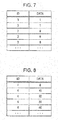
- Fig. 7 is a diagram illustrating examples of sets each including an ID (a message ID) and a data field (data) for frames transmitted from the ECU 100d connected to the door open/close sensor 103.
- Each frame transmitted by the ECU 100c is assigned "3" as its message ID.
- the data represents an open/close state of a door.
- the data length thereof is 1 byte. When the door is in an open state, the data has a value of "1", while when the door is in a closed state, the data has a value of "0".
- message IDs and data of frames sequentially transmitted from the ECU 100c are described row by row from the top row toward lower rows. In this example, data indicates that the open/close state of the door gradually changes from the open state to the closed state.
- Fig. 8 is a diagram illustrating examples of sets each including an ID (a message ID) and a data field (data) for frames transmitted from the ECU 100d connected to the door open/close sensor 104.
- Each frame transmitted by the ECU 100d is assigned "4" as its message ID.
- the data represents an open/close state of a window in percentage (%), and the data length thereof is 1 byte. When the window is in a completely closed state, the value in percentage is 0(%), while when the window is in a completely open state, the value in percentage is 100(%).
- message IDs and data of frames sequentially transmitted from the ECU 100d described row by row from the top row toward lower rows. In this example, data indicates that the open/close state of the window gradually changes from the closed state to the open state.
- Fig. 9 is a diagram illustrating a configuration of the gateway 300.
- the gateway 300 includes a frame transmission/reception unit 310, a frame interpreter 320, an acceptance ID judgment unit 330, an acceptance ID list storage 340, a conversion processing unit 350, an external communication unit 360, a vehicle identification information storage 361, an abnormality detection processor 370, a model storage 371, a transfer processor 380, a transfer rule storage 381, and a frame generator 390.
- Each function of each of these constituent elements is realized, for example, by a communication circuit in the gateway 300, a processor, or a digital circuit that executes a control program stored in a memory, or the like.
- the frame transmission/reception unit 310 transmits and receives, according to the CAN protocol, frames to and from the bus 200a and the bus 200b respectively.
- the frame transmission/reception unit 310 functions as a receiver that receives a frame from the bus on a bit-by-bit basis, and transfers the received frame to the frame interpreter 320. Furthermore, based on a frame and bus information indicating a destination bus received from the frame generator 390, the frame transmission/reception unit 310 transmits a content of the frame to the bus 200a or the bus 200b on a bit-by-bit basis.
- the frame interpreter 320 receives values of the frame from the frame transmission/reception unit 310 and interprets the values such that the values are mapped to fields according to the frame format defined in the CAN protocol. A value determined to be mapped to an ID field is transferred to the acceptance ID judgment unit 330. According to a judgment result notified from the acceptance ID judgment unit 330, the frame interpreter 320 determines whether the value of the ID field and the data field (data) following the ID field are to be transferred to the transfer processor 380, or receiving of frames is to be stopped after the judgment result is received. As for a value determined to be mapped to the ID field, the frame interpreter 320 notifies the conversion processing unit 350 of the value of the ID field.
- the frame interpreter 320 In a case where a frame is judged, by the frame interpreter 320, as a frame that is not according to the CAN protocol, the frame interpreter 320 notifies the frame generator 390 that an error frame is to be transmitted. In a case where the frame interpreter 320 receives an error frame, that is, in a case where it is determined, from the received value of the frame, that the received frame is an error frame, the frame interpreter 320 discards the frame thereafter, that is, the frame interpreter 320 stops the interpretation of the frame.
- the acceptance ID judgment unit 330 receives the value of the ID field sent from the frame interpreter 320 and judges, according to a list of message IDs stored in the acceptance ID list storage 340, whether to receive fields following the ID field in the frame.
- the acceptance ID judgment unit 330 notifies the frame interpreter 320 of the determination result.
- the acceptance ID list storage 340 stores an acceptance ID list (see Fig. 4 ) which is a list of IDs (message IDs) that the gateway 300 receives.
- the conversion processing unit 350 determines the detection window size based on the information given from the server 400 in terms of the detection window size, and the processing unit 350 holds the determined detection window size. That is, the conversion processing unit 350 functions as a determiner that determines the detection window size. Based on the value of the ID field notified from the frame interpreter 320, the conversion processing unit 350 makes a conversion such that a set of frames sequentially received from the bus 200a or 200b (a set of values of the ID field sequentially notified) in each detection window with a time length corresponding to the detection window size is converted to feature information indicating the number of frames received in the detection window individually for each ID (for each message ID) (that is, the count values obtained by counting the frames received in the detection window with the detection window size individually for the respective IDs), and processing unit 350 sends the feature information to the external communication unit 360.
- the conversion processing unit 350 also functions as an identifier that identifies feature information.
- the conversion processing unit 350 sequentially notifies the abnormality detection processor 370 of the feature information based on the number of frames sequentially received within the detection window with the detection window size from the buses 200a and 200b.
- the external communication unit 360 transmits vehicle identification information held by the vehicle identification information storage 361 to the server 400 via the network 40, and the external communication unit 360 sends, to the conversion processing unit 350, information indicating the detection window size received, as a response, from the server 400.
- the external communication unit 360 also notifies (sends the feature information to) the server 400 of the feature information notified from the conversion processing unit 350.
- the external communication unit 360 provides model information (information representing a criterion model indicating a criterion in terms of an occurrence frequency of data frames) received from the server 400 to the abnormality detection processor 370.
- the external communication unit 360 notifies (transmits the result of the abnormality detection to) the server 400 of the result of the abnormality detection received from the abnormality detection processor 370.
- the vehicle identification information storage 361 stores vehicle identification information for identifying vehicles.
- Fig. 10 illustrates an example of vehicle identification information.
- the abnormality detection processor 370 acquires, via the external communication unit 360, the model information transmitted from the server 400, and, based on the model information, the abnormality detection processor 370 updates a particular model (a model indicating a criterion in terms of the frequency of occurrence of data frames) stored in the model storage 371. For example, the abnormality detection processor 370 may update the particular model so as to become identical to the criterion model indicated by the model information.
- the abnormality detection processor 370 also functions as a judger that receives feature information converted by the conversion processing unit 350 based on a value of the ID field notified from the frame interpreter 320, performs an operation process using the feature information and the particular model stored in the model storage 371, and performs the judgment as to whether the state is abnormal or not based on a result of the operation process. That is, the abnormality detection processor 370 judges whether the feature information associated with the set of frames received from the bus satisfies the criterion indicated by the particular model by performing the operation process using the feature information and the particular model.
- the operation process is defined to achieve the judgment in the above-described manner.
- the operation process is, for example, a combination of one or more processes including a comparison, an arithmetic operation, a logical operation, a conditional judgment, and the like between the particular model and the feature information.
- the abnormality detection processor 370 sends a result of the judgment made by the operation process as to whether the state is abnormal or not (that is, an abnormality detection result) to the external communication unit 360.
- the model storage 371 stores the particular model notified from the abnormality detection processor 370.
- the transfer processor 380 determines the bus to be used in transferring (the transfer destination bus) according to the transfer rule stored in the transfer rule storage 381 depending on the ID of the received frame (the message ID), and the transfer processor 380 sends bus information indicating the bus to be used in the transfer, the message ID notified from the frame interpreter 320, and data to the frame generator 390.
- the transfer rule storage 381 stores the transfer rule that is information indicating the rule of transferring frames for each bus.
- Fig. 11 illustrates an example of a transfer rule.
- the frame generator 390 configures an error frame according to an instruction indicated, in a notification received from the frame interpreter 320, that an error frame is to be transmitted, and the frame generator 390 sends the error frame to the frame transmission/reception unit 310 thereby controlling the frame transmission/reception unit 310 to transmit the error frame.
- the frame generator 390 also configures a frame using data and a message ID notified from the transfer processor 380, and sends the resultant frame and bus information to the frame transmission/reception unit 310.
- Fig. 10 illustrates an example of vehicle identification information held by a gateway 300.
- the vehicle identification information is information for identifying the vehicle.
- Fig. 10 illustrates an example of vehicle identification information indicating a car maker (vehicle manufacturer), a vehicle type, and a chassis number.
- the chassis number is information (information identifying each vehicle) that distinguishes each vehicle from the other vehicles, and the chassis number includes a model (vehicle model) and a serial number.
- vehicles that are the same in type have the same configuration of the on-board network, and have the same specifications in terms of the use of data frames (messages) (the specifications of the content of the data field for each message ID) transmitted over the CAN bus of the on-board network.
- vehicle identification information is not limited to this example, but the vehicle identification information may be, for example, vehicle identification number (VIN) or the like.
- VIN vehicle identification number
- the vehicle identification information does not necessarily need to be information that uniquely identifies a vehicle.
- the vehicle identification information may be information indicating only the type of the vehicle, information indicating only the manufacturer of the vehicle, information indicating only the chassis number, or information which is a combination of one or more of pieces of information described above and another information.
- Fig. 11 illustrates an example of a transfer rule stored in the transfer rule storage 381 of the gateway 300.
- the transfer rule indicates a correspondence between a transfer source bus and a transfer destination bus and an ID of a frame to be transferred (a message ID).
- "*" indicates that frame transfer is performed regardless of the message ID.
- the rule is set such that a frame received from the bus 200a is transferred to the bus 200b regardless of the message ID.
- the rule is also set such that, of frames received from the bus 200b, only frames having a message ID of "3" are transferred to the bus 200a.
- the server 400 is a computer located outside the vehicle and capable of, for example, managing a plurality of vehicles.
- the server 400 includes a storage medium such as a memory, a hard disk, or the like, a processor, a communication circuit, and the like.
- Fig. 12 is a diagram illustrating a configuration of the server 400.
- the server 400 includes, as illustrated in Fig. 12 , a communicator 410, a data accumulation unit 420, a learner 430, a detection window size identification unit 440, a detection window size identification table storage 450, and an abnormality detection result storage 460.
- Each of these constituent elements is realized by a communication circuit in the server 400, a processor or the like that executes a control program stored in a memory, or the like.
- the communicator 410 communicates with the gateway 300 of each vehicle via the network 40. Furthermore, the communicator 410 sequentially receives, from the gateway 300, feature information in which the counts per the detection window size for the respective IDs are reflected, and the communicator 410 accumulates the received feature information in the data accumulation unit 420 separately for the respective vehicles. Furthermore, the communicator 410 notifies (transmits model information to) the gateway 300 of model information indicating the criterion model notified from the learner 430. Furthermore, the communicator 410 notifies the detection window size identification unit 440 of the vehicle identification information notified from the gateway 300, and notifies (transmits information indicating the detection window size to) the gateway 300 of the detection window size notified from the detection window size identification unit 440. Furthermore, the communicator 410 controls the abnormality detection result storage 460 to store an abnormality detection result notified from the gateway 300.
- the data accumulation unit 420 accumulates (stores) the feature information notified from the communicator 410 distinctively for each vehicle.
- the learner 430 constructs the criterion model (the model indicating the criterion in terms of the frequency of occurrence of data frames appearing on a bus of an on-board network of a vehicle) for each vehicle based on the feature information associated with vehicle accumulated in the data accumulation unit 420, and the learner 430 stores the constructed criterion model.
- the learner 430 updates the criterion model, as required, based on the feature information. For example, the learner 430 sequentially updates the stored criterion models, for example, via machine learning based on feature information sequentially collected by the communicator 410 and the data accumulation unit 420.
- the detection window size identification unit 440 refers to a detection window size identification table stored in the detection window size identification table storage 450, and identifies a detection window size depending on vehicle identification information notified from the communicator 410, and the detection window size identification unit 440 notifies the communicator 410 of information indicating the identified detection window size.
- the detection window size identification table storage 450 stores the detection window size identification table used in identifying the detection window size depending on the vehicle identification information.
- Fig. 13 illustrates an example of a detection window size identification table.
- the abnormality detection result storage 460 stores, as a log for each vehicle, the abnormality detection result notified from the communicator 410.
- the information from each vehicle may be classified by the server 400 based on the vehicle identification information received from the vehicle, while the gateway 300 of the vehicle may, for example, attach all or part of the vehicle identification information to the feature information or the abnormality detection result transmitted by the gateway 300 to the server 400.
- Fig. 13 illustrates an example of a detection window size identification table stored in the server 400.
- the detection window size identification table illustrated in Fig. 13 is a table representing a correspondence between vehicle identification information and a detection window size.
- the vehicle identification information in the detection window size identification table illustrated by way of example in Fig. 13 includes, as in the example illustrated in Fig, 10 , a car maker, a vehicle type, and a chassis number.
- the detection window size may be determined, for example, such that the detection window size is equal to a transmission period of a type of data frame whose transmission period is the shortest of a plurality of types of data frames (that is, a plurality of data frames with message IDs different from each other) to be transmitted in a normal state over a CAN bus in the on-board network system of each vehicle in a set of vehicles identified by the vehicle identification information.
- information may be referred to as to specifications of the on-board network system or a result of analysis of current situations, in terms of normal state, of the on-board network system.
- the detection window size may be determined so as to be equal to the shortest one of the transmission periods of frames of a plurality of IDs to be transmitted in a normal state in the on-board network system of each vehicle of the type of interest.
- the detection window size in the detection window size identification table may be determined in other ways. In any case, it is useful to determine the detection window size such that it is possible to properly distinguish, by the abnormality detection apparatus (the gateway 300) of a vehicle, between a normal state and a state in which an attack occurs.
- Fig. 14 illustrates an example of a frame transmission process sequence performed by the ECU 100a. Referring to Fig. 14 , the frame transmission process by the ECU 100a is described below.
- the ECU 100a acquires, by the data acquisition unit 160, data from a sensor (in terms of, for example, a vehicle speed obtained by measuring, for example, a parameter of the engine 101 by the sensor) (step S1101).
- a sensor in terms of, for example, a vehicle speed obtained by measuring, for example, a parameter of the engine 101 by the sensor
- the ECU 100a Based on the data acquired from the sensor, the ECU 100a generates, by the frame generator 170, a frame (a data frame) to be transmitted (step S1102).
- step S1103 the ECU 100a transmits (broadcasts) the generated frame to the bus 200a (step S1103).
- the process from step S1101 to step S1103 is generally repeated periodically at fixed intervals.
- the frame transmission process may be performed according to a procedure similar to that by the ECU 100a. However, the transmission repetition period may be different between the respective ECUs.
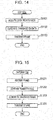
- Fig. 15 illustrates an example of a frame transfer process sequence performed in the gateway 300.
- the gateway 300 performs the frame transfer process each time a frame (a data frame) is received from either one of the bus 200a and the bus 200b.
- a frame a data frame
- the gateway 300 transfers a frame received from the bus 200a to the bus 200b.
- the gateway 300 receives a frame transmitted (broadcast) to the bus 200a (step S1201).
- the gateway 300 confirms the transfer rule (see Fig. 11 ) (step S1202).
- the gateway 300 In a case where the judgment by the gateway 300 based on the transfer rule is that the received frame is a frame to be transferred, the gateway 300 generates a frame to be transferred based on the content of the received frame (step S1203).
- the gateway 300 transmits (broadcasts) the frame to be transferred to the bus 200b, and ends the frame transfer process (step S1204).
- the gateway 300 ends the frame transfer process without transferring the frame.
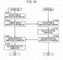
- Fig. 16 illustrates an example of a detection window size determination sequence performed, in cooperation, by the gateway 300 and the server 400. Referring to Fig. 16 , the detection window size determination sequence is described below.
- the gateway 300 acquires vehicle identification information (step S1301).
- the acquisition of the vehicle identification information by the gateway 300 is from the vehicle identification information storage 361.
- the vehicle identification information storage 361 may store the vehicle identification information, for example, when the gateway 300 is installed in the vehicle (for example, when the vehicle is produced), or the gateway 300 may receive vehicle identification information of an ECU from this ECU in a vehicle including prestored vehicle identification information and the vehicle identification information storage 361 may store the received vehicle identification information.
- the gateway 300 transmits the vehicle identification information acquired in step S1301 to the server 400 (step S1302a).
- the server 400 receives the vehicle identification information (step S1302b).
- the transmission of the vehicle identification information from the gateway 300 to the server 400 is performed, for example, when the gateway 300 is installed in the vehicle (for example, when the vehicle is produced).
- the transmission of the vehicle identification information may be performed at another time or may be performed at one of a plurality of times.
- Timings of the transmission is each time the vehicle is used such as driving of the vehicle is started (for example, each time the engine of the vehicle is started or each time an accessory is turned on (ACC-ON), or the like), each time a particular time elapses (for example, one every day), or the like.
- the whole of the detection window size determination sequence illustrated in Fig. 16 may be executed.
- the detection window size identification unit 440 identifies the detection window size according to the vehicle identification information received in step S1302b (step S1303), and the detection window size identification unit 440 transmits, as a response to the vehicle identification information, information (detection window size information) indicating the identified detection window size to the gateway 300 (step S1304a).
- the gateway 300 receives the detection window size information (step S1304b).
- the conversion processing unit 350 determines the detection window size according to the received detection window size information, and stores the detection window size (step S1305).
- Fig. 17 illustrates an example of a learning process sequence performed, in cooperation, by the gateway 300 and the server 400.
- the learning process sequence feature information obtained as a result of performing the conversion process on a set of frames received by the gateway 300 in the on-board network of the vehicle is transmitted to the server 400, and the server 400 modifies the criterion model such that the feature information is reflected in the criterion model.
- the learning process sequence is described below.
- the gateway 300 When the gateway 300 receives a frame (a data frame) from the bus 200a or the bus 200b in each detection window with a time length corresponding to the detection window size stored in the conversion processing unit 350 (step S1401), the gateway 300 increments the count of frames received within the detection window for corresponding one of the IDs (message IDs) (step S1402).
- the conversion processing unit 350 judges an elapsed time corresponding to the detection window size (that is, an arrival of an end of one detection window) (step S1403).
- the conversion processing unit 350 performs a conversion process based on the number of received frames (the number of counts) for each ID thereby generating feature information (step S1404).
- the gateway 300 transmits the feature information generated by the conversion processing unit 350 to the server 400 (step S1405a), and the conversion processing unit 350 clears the number of counts (step S1406).
- the gateway 300 returns to the process of detecting a next detection window (that is, the gateway 300 returns to the process in step S1401). Note that in a case where it is determined in step S1403 that an end of a detection window has not yet come, the gateway 300 returns to the process in step S1401.
- the server 400 receives the feature information (step S1405b), and the learner 430 modifies the criterion model such that the received feature information in the criterion model (step S1407).
- the server 400 may modify the criterion model such that the feature information is reflected in the criterion model, or a plurality of pieces of received feature information may be accumulated in the data accumulation unit 420, and the learner 430 may update the criterion model such that the plurality of pieces of feature information are reflected at a time in the criterion model.
- the criterion model is updated such that the feature information associated with a frame received in a normal state in the on-board network of the vehicle is reflected in the criterion model thereby allowing the criterion model to be used as the criterion in terms of the frequency of occurrence of frames appearing on the bus of the on-board network of the vehicle.
- the criterion model is defined, for example, individually for each piece of vehicle identification information acquired from vehicles.
- the criterion model may be defined, for example, for each vehicle. However, the same criterion model may be shared by vehicles of the same vehicle type.
- a criterion model corresponding to a vehicle to which information indicating a detection window size is transmitted by the server 400 depending on the vehicle identification information from the vehicle and model information indicating this criterion model is transmitted to the vehicle in a model update process sequence described later.
- the modification of the criterion model such that the feature information is reflected in the criterion model may be performed, for example, by updating the criterion model via machine learning using the feature information.
- FIG. 18 an example of a detection window with a time length corresponding to the detection window size used in the learning process sequence and an example of feature information generated by the conversion process are described below.
- feature information based on the number of frames received in the detection window from the bus is identified for each of periods (for each of detection windows T1, T2, and T3) each having a time length corresponding to the detection window size.
- a feature vector whose components indicate the numbers of received frames counted for the respective IDs is identified as feature information.
- a frame with an ID of 1 is denoted by ID1
- a frame with an ID of 2 is denoted by ID2, and so on.
- the feature vector is a vector whose components respectively indicate, for example, the number of frames (the counts) of ID1 received in the detection window, the number of frames of ID2 received in the detection window, the number of frames of ID3 received in the detection window, and the number of frames of ID4 received in the detection window.
- the number of components of the vector is equal to, for example, the total number of all message IDs that appear on the bus.
- components respectively indicating the numbers of frames of ID1, ID2, ID3, and ID4 are arranged in this order.
- the number of received frames is 1 for each of ID1, ID2, and ID3, while the number of received frames is 0 for ID4, and thus the feature vector in the detection window T1 is given as [1, 1, 1, 0,...].
- the number of received frames is 1 for each of ID1, ID2, and ID4, while the number of received frames is 0 for ID3, and thus the feature vector in the detection window T2 is given as [1, 1, 0, 1,...].
- the number of received frames is 1 for each of ID1 and ID3, while the number of received frames is 0 for each of ID2 and ID4, and thus the feature vector in the detection window T3 is given as [1, 0, 1, 0,...].
- the gateway 300 and the server 400 may cooperate in an arbitrary manner in performing the process (the conversion process and the like) to modify the criterion model of the server 400 such that the number of frames received by the gateway 300 within the period with the detection window size as counted individually for the respective IDs.
- principal component analysis or the like may be used to reduce the dimension (the number of components) of the feature vector serving as the feature information.
- a conversion may be performed to make it possible to efficiently detect an abnormality in the gateway 300 by using a particular model similar to the criterion model.
- the server 400 may perform a conversion such that a set of feature vectors with reduced dimension serving as the feature information sequentially acquired from the gateway 300 has a data structure such as a k-dimensional tree or the like that is suitable for calculating a nearest neighbor distance.
- Fig. 19 illustrates an example of a model update process sequence performed, in cooperation, by the gateway 300 and the server 400.
- the criterion model updated in the server 400 is reflected in the particular model stored in the gateway 300 of the vehicle.
- the model update process sequence is described below.
- the model update process sequence is executed at an arbitrary time (for example, once every day).
- the server 400 judges whether the criterion model has been updated as a result of the learning process sequence (whether a change in the content of the criterion model has occurred) (step S1501). In a case where the criterion model has been updated, the server 400 transmits model information indicating the updated criterion model to the gateway 300 (step S1502a). In response, the gateway 300 receives the model information indicating the criterion model (step S1502b).
- the abnormality detection processor 370 in the gateway 300 Upon receiving the model information, the abnormality detection processor 370 in the gateway 300 updates the particular model stored in the model storage 371 according to the model information (step S1503). As a result, the particular model becomes identical, for example, to the criterion model in the server 400.
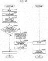
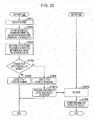
- Fig. 20 illustrates an example of an abnormality detection process sequence performed, in cooperation, by the gateway 300 and the server 400.
- the abnormality detection process sequence is executed, for example, at a stage where the vehicle is used.
- the abnormality detection process sequence includes a process in which the gateway 300 monitors frames transmitted on the buss 200a and 200b of the on-board network of the vehicle and detects an abnormality by making a judgment using the particular model as to whether the state is abnormal. Via the model update process sequence described above, the particular model becomes identical to the criterion model updated in the learning process sequence described above.
- the learning process sequence described above may be performed before the abnormality detection process sequence (for example, before the vehicle is used, and more particularly, when the vehicle is produced or subjected to testing or the like). Alternatively, the learning process sequence may be performed in parallel to the abnormality detection process sequence when the vehicle is used. Referring to Fig. 20 , the abnormality detection process sequence is described below.
- step S1601 when a frame is received, (step S1601), the conversion processing unit 350 counts the number of frames received in a detection window with a detection window size for each ID (step S1602), and the conversion processing unit 350 performs the conversion process to generate, for example, a feature vector serving as feature information (step S1603).
- the process from step S1601 to step S1602 is performed repeatedly in each detection window.
- step S1603 is performed to generate feature information, and the counter that counts the number of received frames for each ID is cleared.
- the abnormality detection processor 370 receives feature information generated by the conversion processing unit 350 and judges whether the feature information is consistent or inconsistent with the criterion indicated by the particular model stored in the model storage 371 (step S1604). That is, the abnormality detection processor 370 performs an operation process using the feature information and the particular model, and makes a judgment based on a result of the operation process as to whether the feature information is inconsistent with the criterion indicated by the feature information (that is, whether there is an abnormality).
- An example of the operation process is to calculate the nearest neighbor distance of the feature vector (see Fig.
- the nearest neighbor distance serving as the feature information received from the conversion processing unit 350 to the criterion (for example, the distribution of the feature vector in the normal state) indicated by the particular model represented in a data structure such as a k-dimensional tree or the like, and compare the calculated nearest neighbor distance with a threshold value. For example, when the nearest neighbor distance distributes according to the normal distribution, if the nearest neighbor distance is out of a range defined by a threshold value, for example a range of a standard deviation times a particular value (for example, 3) from the average defined by a threshold value, then it is judged that there is an abnormality.
- a threshold value for example a range of a standard deviation times a particular value (for example, 3) from the average defined by a threshold value
- step S1604 determines that the feature information is not inconsistent with the criterion indicated by the particular model (that is, the feature information is consistent with the criterion)
- the gateway 300 judges that the state is normal (step S1605), and the gateway 300 does not transmit particular information to the server 400.
- step S1606 judges that the state is abnormal (step S1606), and the gateway 300 transmits an abnormality detection result to the server 400 (step S1607a).
- the server 400 When the server 400 receives the abnormality detection result (step S1607b), the server 400 stores the abnormality detection result as a log (step S1608).
- the gateway 300 functioning as the abnormality detection apparatus installed in the vehicle transmits the vehicle identification information for identifying the vehicle to the server 400, and, based on a response returned from the server 400, the gateway 300 determine the detection window size (the unit time within which the number of frames received is counted to detect an abnormality). This makes it possible to make an accurate detection of an abnormality of an on-board network using the detection window size determined properly for each vehicle. Furthermore, in the abnormality detection system 10, to learn the model (the particular model or the criterion model) used in judging (detecting) an abnormality, the conversion process to generate the feature vector of the received frame is performed by the gateway 300 thereby allowing a reduction in the amount of data transmitted between the gateway 300 and the server 400.
- the server 400 may accumulate data (feature information received from vehicles) and construct the model (updating the criterion model or the like) such that the feature information is reflected in the model thereby making it possible to construct the optimum model without being limited by a limited resource of the gateway 300 installed in the vehicle.
- the criterion model constructed (updated) by the server 400 is acquired by the gateway 300 and is used to make the judgment (detection) as to an abnormality thereby making it possible to quickly judge whether there is an abnormality in the vehicle (that is, to detect an abnormality).
- the gateway 300 then notifies the server 400 of the abnormality detection result.
- the server 400 stores the abnormality detection result as a log, which makes it possible to manage the vehicle. Furthermore, it becomes possible to construct a better criterion model based on the abnormality detection result.
- the server 400 may collect feature information from a plurality of vehicles of the same vehicle type and may properly construct the criterion model for this vehicle type such that it becomes possible to distinguish a normal state and a state in which an attack to this type occurs.
- the server 400 may transmit the model information indicating the criterion model to the gateway 300 of vehicles of this same type thereby making it possible for each vehicle of this type to properly detect an abnormality based on a particular model similar to the criterion model.
- it becomes possible to perform various processes to handle the abnormality such as generating a warm, controlling the running of the vehicle so as to achieve safety, or the like).
- the detection window size is determined by the gateway 300 of the vehicle via the communication with the server 400 located outside the vehicle, and feature information based on the number of frames received in a time period corresponding to the detection window size counted individually for each ID is transmitted to the server 400 to allow it to update, via learning, the criterion model serving as the basis of the particular model used in detecting an abnormality in the on-board network.
- a detection window size used in detecting an abnormality is determined independently by an abnormality detection apparatus of an on-board network system of a vehicle (that is, independently of a server located outside the vehicle).
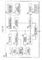
- Fig. 21 illustrates a configuration of an on-board network system in a vehicle according to the present embodiment.
- elements similar to those in the first embodiment are referred to by the same symbols as in Fig. 1 , and a description thereof is omitted.
- the on-board network system of the vehicle illustrated in Fig. 21 includes an ECU 100a, an ECU 100b, an ECU 100c, an ECU 100d, buss 200a and 200b, and a gateway 1300 (example of an abnormality detection apparatus).
- Each ECU is capable of transmitting and receiving frames via the bus 200a or 200b of the vehicle according to the CAN protocol.
- the gateway 1300 is an abnormality detection apparatus obtained by partially modifying the gateway 300 according to the first embodiment described above, and elements which are not described below are similar to those of the gateway 300.
- the gateway 1300 is connected to buses 200a and 200b, and has a function of transferring a frame received from one bus to the other bus, and a function of detecting an abnormality by making a judgment based on the frame received from the bus (for example, by judging whether the current state is an abnormal state in which an attack frame is flowing through the bus).
- the gateway 1300 also has a function of determining a detection window size for use in the abnormality detection (the judgment as to whether there is an abnormality or not), and a function of updating a particular model for use in the abnormality detection depending on feature information in terms of the number of frames received by the on-board network within the detection window having a time period equal to the detection window size.
- Fig. 22 is a diagram illustrating a configuration of the gateway 1300.
- the gateway 1300 includes a frame transmission/reception unit 310, a frame interpreter 320, a reception ID judgement unit 330, an acceptance ID list storage 340, a processing unit 1350, a vehicle identification information storage 361, an abnormality detection processor 1370, a model storage 1371, a transfer processor 380, a transfer rule storage 381, a frame generator 390, a detection window size determination unit 1440, a detection window size identification table storage 450, a learner 1430, and an abnormality detection result storage 1460.
- each function of each of these constituent elements is realized, for example, by a communication circuit in the gateway 1300, a processor or a digital circuit that executes a control program stored in a memory, or the like.
- a communication circuit in the gateway 1300 a processor or a digital circuit that executes a control program stored in a memory, or the like.
- elements similar to those of the gateway 300 illustrated in Fig. 9 or elements similar to those of the server 400 illustrated in Fig. 12 are denoted in Fig. 22 by the same symbols as those in Fig. 9 or Fig. 12 , and a description thereof is omitted.
- the detection window size determination unit 1440 functions as a determiner that determines the detection window size.
- the detection window size determination unit 1440 determines, depending on the vehicle identification information stored in the vehicle identification information storage 361, the detection window size using the detection window size identification table (see Fig. 13 ) stored in the detection window size identification table storage 450, and notifies the processing unit 1350 of the determined detection window size.
- the processing unit 1350 is a processing unit obtained by partially modifying the conversion processing unit 350 according to the first embodiment described above.
- the processing unit 1350 stores a detection window size notified from the detection window size determination unit 1440, and makes a conversion based on a value of an ID field notified from the frame interpreter 320 such that a set of frames sequentially received from the bus 200a or 200b (a set of values of the ID field sequentially notified) in each detection window with a time length corresponding to the detection window size is converted to feature information indicating the number of frames received in the detection window for each ID (for each message ID) (that is, the count values obtained by counting the frames received in the detection window with the detection window size individually for the respective IDs), and processing unit 1350 periodically sends the feature information to the learner 1430.
- the processing unit 1350 functions as an identifier that identifies feature information. Furthermore, the processing unit 1350 sequentially sends, to the abnormality detection processor 1370, the feature information of frames based on the number of frames sequentially received from the bus 200a or 200b within the detection window with the detection window size.
- the model storage 1371 stores a particular model (a model indicating a criterion in terms of the frequency of occurrence of data frames appearing on a bus of the on-board network of the vehicle).
- the learner 1430 constructs the particular model based on the feature information notified from the processing unit 1350, and stores the constructed particular model in the model storage 1371. That is, the learner 1430 updates the particular model stored in the model storage 1371 based on the feature information.
- the updating of the particular model by the learner 1430 may be performed in a similar manner to the manner of updating the criterion model by the learner 430 according to the first embodiment described above.
- the learner 1430 may sequentially update the particular model, for example, by machine learning, for example, based on sequentially notified feature information.
- the abnormality detection processor 1370 receives the feature information generated by the processing unit 1350 based on the value of the ID field notified from the frame interpreter 320, and the abnormality detection processor 1370 performs an operation process using the received feature information and the particular model stored in the model storage 1371 and makes a judgment based on a result of the operation process as to whether there is an abnormality or not. That is, the abnormality detection processor 1370 functions as a judger that judges, by performing the operation process using the feature information and the particular model, whether the feature information associated with a set of frames received from the bus is consistent with the criterion indicated by the particular model.
- the state is judged as normal, while when the criterion is not satisfied (that is, when the feature information is inconsistent with the criterion), the state is judged as abnormal.
- the abnormality detection processor 370 stores a result of the judgment by the operation process as to the abnormality (that is, an abnormality detection result) as a log in the abnormality detection result storage 1460.
- Fig. 23 illustrates an example of a detection window size determination sequence in the gateway 1300.
- the timing of executing the detection window size determination sequence may be, for example, when the gateway 1300 is installed in the vehicle (for example, when the vehicle is produced), or another timing or a plurality of timings may be employed.
- the detection window size determination sequence may be executed each time the vehicle is used (for example, each time the engine of the vehicle is started or each time an accessory is turned on (ACC-ON), or the like), or each time a particular time elapses (for example, one every day). Note that steps similar to those in Fig. 16 are denoted in Fig. 23 by the same symbols as those in Fig. 16 , and a description thereof is omitted.
- the gateway 1300 acquires vehicle identification information (step S1301).
- the gateway 1300 determines the detection window size using a detection window size identification table (see Fig. 13 ) according to the vehicle identification information acquired in step S1301 (step S2303).
- the gateway 1300 stores the determined detection window size such that the detection window size is allowed to be used when the processing unit 1350 performs the conversion process.
- the gateway 1300 may having a function of communicating with the outside of the vehicle.
- the detection window size identification table may be acquired from the outside of the vehicle via communication, or the detection window size identification table may be acquired by reading it from a storage medium or the like.
- Fig. 24 illustrates an example of the learning process sequence performed in the gateway 1300.
- the gateway 1300 updates the particular model stored in the model storage 1371 by performing learning based the feature information obtained by performing the conversion process on a set of frames received from the bus 200a or 200b.
- the learning process sequence is described below. Note that steps similar to those in Fig. 17 are denoted in Fig. 24 by the same symbols as those in Fig. 17 , and a description thereof is omitted.
- step S1401 Each time the gateway 1300 receives a frame from the bus 200a or the bus 200b in each detection window with a time length equal to the detection window size (step S1401), the gateway 1300 increments the count of frames received within the detection window for corresponding one of the IDs (step S1402).
- the processing unit 1350 When a time corresponding to the detection window size has elapsed (when the end of a detection window comes), the processing unit 1350 generates the feature information by performing the conversion process based on the number (the count) of received frames for each ID (step S1404).
- the gateway 1300 modifies the particular model stored in the model storage 1371 such that the feature information generated by the processing unit 1350 is reflected in the particular model (step S2407). It is assumed that the learning process sequence modifies the particular model such that the feature information associated with frames received in the normal sate in the on-board network is reflected in the particular model and thus such that the particular model provides a criterion in terms of the frequency of occurrence of frames on the bus of the on-board network.
- the modifying of the particular model such that the feature information is reflected in the particular model may be accomplished, for example, by updating the particular model via machine learning using the feature information.
- the processing unit 1350 may employ, as the feature information, a feature vector including components indicate the numbers of frames received within the detection window for the respective message IDs as with the conversion processing unit 350 according to the first embodiment described above.
- the processing unit 1350 may reduce the dimension of the feature vector by using the principal component analysis or the like in the conversion process.
- the learner 1430 may perform a conversion process such that it becomes possible to efficiently perform the abnormality detection using the particular model. For example, in the modification of the particular model so as to reflect the feature information, the learner 1430 converts the set of feature vectors so as to have a data structure such as a k-dimensional tree or the like suitable for calculating the nearest neighbor distance.
- the gateway 1300 clears the count value (step S1406), and returns to the process in step S1401.
- Fig. 25 illustrates an example of the abnormality detection process sequence performed in the gateway 1300.
- the abnormality detection process sequence is executed, for example, at a stage where the vehicle is used.
- the gateway 1300 monitors frames transmitted on the buss 200a and 200b of the on-board network of the vehicle, and detects an abnormality by making a judgment using the particular model as to whether an abnormal state occurs.
- the learning process sequence described above may be performed before the abnormality detection process sequence (for example, before the vehicle is used, and more particularly, when the vehicle is produced or subjected to testing or the like). Alternatively, the learning process sequence may be performed in parallel to the abnormality detection process sequence when the vehicle is used. Referring to Fig. 25 , the abnormality detection process sequence is described below. Note that steps similar to those in Fig. 20 are denoted in Fig. 25 by the same symbols as those in Fig. 20 , and a description thereof is omitted.
- step S1601 when a frame is received, (step S1601), the processing unit 1350 counts the number of frames received in a detection window with a detection window size for each ID (step S1602), and the conversion processing unit 1350 performs the conversion process to generate, for example, a feature vector serving as feature information (step S1603).
- the process from step S1601 to step S1602 is performed repeatedly in each detection window.
- step S1603 is performed to generate feature information, and the counter that counts the number of received frames for each ID is cleared.
- the abnormality detection processor 1370 receives feature information generated by the processing unit 1350 and judges whether the feature information is consistent or inconsistent with a criterion indicated by a particular model stored in the model storage 1371 (step S1604).
- step S1604 In a case where it is determined in step S1604 that the feature information is not inconsistent with the criterion indicated by the particular model (that is, the feature information consistent with the criterion), the gateway 1300 judges that the state is normal (step S1605). On the other hand, in a case where it is judged that the feature information is inconsistent with the criterion indicated by the particular model, the gateway 1300 judges that the state is abnormal (step S1606), and the gateway 1300 stores a judgment result as a log (step S2608). Note that the gateway 1300 may use this judgment result in machine learning (for example, supervised learning) or the like thereby updating the particular model.
- machine learning for example, supervised learning
- the abnormality detection apparatus (the gateway 1300) according to the second embodiment is capable of determining, without communicating with a server or the like, the detection window size (the unit time in which the number of received frames is counted to detect an abnormality) such that vehicle identification information for identifying the vehicle in which the abnormality detection apparatus is installed is acquired and the detection window size is determined depending on the acquired vehicle identification information. This makes it possible for the gateway 1300 to accurately detect an abnormality in the on-board network by using the detection window size suitable for the vehicle in which the gateway 1300 is installed.
- the gateway 1300 it becomes possible for the gateway 1300 to construct a particular model (update the particular model or the like) such that the feature information generated based on monitoring of the on-board network is reflected in the particular model, and make a judgment (detection) on the abnormality using the particular model, which makes it possible to quickly judge whether the state is abnormal in the vehicle (that is, to detect an abnormality). Furthermore, the gateway 1300 is capable of storing, as a log, a result of the judgment as to the abnormality such that the judgment result is used.
- the present disclosure is applicable to detection of an attack to an on-board network.
Landscapes
- Engineering & Computer Science (AREA)
- Computer Networks & Wireless Communication (AREA)
- Signal Processing (AREA)
- Computer Security & Cryptography (AREA)
- Computer Hardware Design (AREA)
- General Engineering & Computer Science (AREA)
- Theoretical Computer Science (AREA)
- Environmental & Geological Engineering (AREA)
- Computing Systems (AREA)
- Physics & Mathematics (AREA)
- General Physics & Mathematics (AREA)
- Software Systems (AREA)
- Small-Scale Networks (AREA)
Claims (16)
- Anomalitätsdetektionsverfahren zum Detektieren einer Anomalität in einem fahrzeuginternen Netzwerksystem, wobei das fahrzeuginterne Netzwerksystem mehrere elektronische Steuereinheiten (100a - 100d) aufweist, die Nachrichten über einen Bus (200a, 200b) in einem Fahrzeug gemäß einem CAN-, Steuerungsbereichsnetzwerk-, Protokoll senden und empfangen, wobei jede der mehreren elektronischen Steuereinheiten periodisch Nachrichten mit festen Intervallen sendet, wobei das Anomalitätsdetektionsverfahren umfasst:Bestimmen (S1305) einer Einheitszeit;Zählen (S1602) der Anzahl an Nachrichten, die aus dem Bus (200a, 200b) in einem Detektionsfenster mit der bestimmten Einheitszeit empfangen werden;Erzeugen (S1603), am Ende des Detektionsfensters, einer Eigenschaftsinformation auf der Grundlage der Anzahl an Nachrichten, die aus dem Bus (200a, 200b) empfangen werden; undBeurteilen (S1604), ob es eine Anomalität gibt, gemäß einem Ergebnis einer Operation, die unter Anwendung der Eigenschaftsinformation und eines speziellen Modells, das ein Kriterium in Form einer Nachrichtenauftrittshäufigkeit angibt, ausgeführt wird.
- Anomalitätsdetektionsverfahren nach Anspruch 1, wobei
jede Nachricht eine Nachrichtenkennung, die eine Nachrichtenart kennzeichnet, enthält, und wobei das Anomalitätsdetektionsverfahren die Schritte umfasst Ausführen der Bestimmung (S1305) der Einheitszeit;
Zählen (S1602) der Anzahl an Nachrichten, die aus dem Bus (200a, 200b) in dem Detektionsfenster empfangen werden, individuell für jede Nachrichtenkennung;
Identifizieren (S1603), als die Eigenschaftsinformation, eines Eigenschaftsvektors, der Komponenten enthält, die den jeweiligen Nachrichtenkennungen zugeordnet sind und die entsprechend die Anzahlen an Nachrichten der zugeordneten Nachrichtenkennungen, die aus dem Bus innerhalb des Detektionsfensters mit der in dem Bestimmungsschritt bestimmten Zeiteinheit empfangen werden, kennzeichnen, und
Ausführen der Beurteilung (S1604) gemäß einem Ergebnis der Operation, die unter Anwendung des speziellen Modells und der Eigenschaftsinformation, die in dem Identifizierungsschritt ermittelt wird, ausgeführt wird. - Anomalitätsdetektionsverfahren nach Anspruch 2, wobei in dem Bestimmungsschritt (S1305) die Einheitszeit auf der Grundlage der Fahrzeugidentifizierungsinformation zum Identifizieren des Fahrzeugs bestimmt wird.
- Anomalitätsdetektionsverfahren nach Anspruch 3, wobei die Fahrzeugidentifizierungsinformation einen Hersteller des Fahrzeugs bezeichnet.
- Anomalitätsdetektionsverfahren nach Anspruch 3, wobei die Fahrzeugidentifizierungsinformation eine Art des Fahrzeugs bezeichnet.
- Anomalitätsdetektionsverfahren nach Anspruch 3, wobei die Fahrzeugidentifizierungsinformation eine Information ist, die das Fahrzeug von anderen Fahrzeugen unterscheidet.
- Anomalitätsdetektionsverfahren nach einem der Ansprüche 3 bis 6, wobei in dem Bestimmungsschritt (S1305) die Einheitszeit so bestimmt wird, dass sie gleich einer Übertragungsperiode einer Art von Nachrichten ist, deren Übertragungsperiode die kürzeste aus den mehreren unterschiedlichen Arten von Nachrichten ist, die in einem normalen Zustand über einen fahrzeuginternen Bus in einem fahrzeuginternen Netzwerksystem eines Fahrzeugs, das in einer Gruppe aus Fahrzeugen enthalten ist, die durch die Fahrzeugidentifizierungsinformation gekennzeichnet ist, zu übertragen sind.
- Anomalitätsdetektionsverfahren nach einem der Ansprüche 3 bis 7, wobei in dem Beurteilungsschritt (S1604) die Operation unter Anwendung des speziellen Modells, das der Fahrzeugidentifizierungsinformation entspricht, ausgeführt wird.
- Anomalitätsdetektionsverfahren nach einem der Ansprüche 2 bis 8, wobei
in dem Identifizierungsschritt (S1603) die Eigenschaftsinformation auf der Grundlage der Anzahl an Nachrichten ermittelt wird, die aus dem Bus (200a, 200b) innerhalb des Detektionsfensters mit der in dem Bestimmungsschritt bestimmten Einheitszeit empfangen werden, wobei der Zählschritt (S1602) und der Identifizierungsschritt (S1603) der Reihe nach in jeder Periode mit einer Länge, die gleich der bestimmten Einheitszeit ist, ausgeführt werden, und
in dem Beurteilungsschritt (S1604) die Operation unter Anwendung des speziellen Modells und jedes Elements der Eigenschaftsinformation, das der Reihe nach in dem Identifizierungsschritt ermittelt wird, ausgeführt wird,
und wobei das Anomalitätsdetektionsverfahren ferner den Schritt umfasst:
sequentielles Aktualisieren (S1503) des speziellen Modells auf der Grundlage der mehreren Elemente der Eigenschaftsinformation, die der Reihe in dem Identifizierungsschritt (S1603) ermittelt werden. - Anomalitätsdetektionsverfahren nach einem der Ansprüche 2 bis 9, wobei
in dem Bestimmungsschritt (S1305) die Einheitszeit in dem Fahrzeug auf der Grundlage einer Information bestimmt wird, die bei der Herstellung des Fahrzeugs festgelegt wurde, und
in dem Identifizierungsschritt (S1603) die Eigenschaftsinformation in dem Fahrzeug ermittelt wird. - Anomalitätsdetektionsverfahren nach einem der Ansprüche 2 bis 9, wobei
in dem Bestimmungsschritt (S1305) die Einheitszeit in dem Fahrzeug bestimmt wird, wenn ein Motor oder Zusatzgerät des Fahrzeugs eingeschaltet wird, und
in dem Identifizierungsschritt (S1603) die Eigenschaftsinformation in dem Fahrzeug ermittelt wird. - Anomalitätsdetektionsverfahren nach einem der Ansprüche 2 bis 9, wobei
in dem Bestimmungsschritt (S1305) die Einheitszeit bei jeder vordefinierten Zeitperiode bestimmt wird,
in dem Identifizierungsschritt (S1603) die Eigenschaftsinformation auf der Grundlage der Anzahl der Nachrichten ermittelt wird, die aus dem Bus (200a, 200b) innerhalb des Detektionsfensters mit einer Einheitszeit empfangen werden, die in dem Bestimmungsschritt aktuell bestimmt wird, wobei das Zählen (S1602) und das Identifizieren (S1603) der Reihe nach in jeder Periode mit einer Länge ausgeführt werden, die gleich der aktuell bestimmten Einheitszeit ist, und
in dem Beurteilungsschritt (S1604) die Operation an jedem der Elemente der Eigenschaftsinformation, die der Reihe nach in dem Identifizierungsschritt ermittelt wurde, unter Anwendung des speziellen Modells und jedes Elements der Eigenschaftsinformation ausgeführt wird. - Anomalitätsdetektionsverfahren nach Anspruch 1, wobei
die Nachricht eine Nachrichtenkennung, die eine Nachrichtenart bezeichnet, enthält, und die Eigenschaftsinformation die Gesamtanzahl aller Nachrichten angibt, die aus dem Bus innerhalb des Detektionsfensters mit der vorbestimmten Einheitszeit empfangen werden. - Anomalitätsdetektionsvorrichtung (300, 1300), die ausgebildet ist, eine Anomalität zu erfassen, wobei die Anomalitätsdetektionsvorrichtung mit einem Bus (200a, 200b) in einem fahrzeuginternen Netzwerksystem verbunden ist, wobei das fahrzeuginterne Netzwerksystem mehrere elektronische Steuereinheiten (100a - 100d) enthält, die Nachrichten über den Bus (200a, 200b) in einem Fahrzeug gemäß einem CAN-, Steuerungsbereichsnetzwerk-, Protokoll senden und empfangen, wobei jede der mehreren elektronischen Steuereinheiten Nachrichten periodisch mit festen Intervallen sendet, wobei die Anomalitätsdetektionsvorrichtung (300, 1300) aufweist:einen Empfänger (310), der ausgebildet ist, eine Nachricht aus dem Bus (200a, 200b) zu empfangen;eine Bestimmungseinheit (360, 1440), die ausgebildet ist, eine Einheitszeit zu bestimmen;eine Identifizierungseinheit (350, 1350), die ausgebildet ist, die Anzahl an Nachrichten zu zählen, die aus dem Bus (200a, 200b) in einem Detektionsfenster mit der bestimmten Einheitszeit empfangen werden, und am Ende des Detektionsfensters eine Eigenschaftsinformation auf der Grundlage der Anzahl an Nachrichten zu erzeugen, die mittels des Empfängers (310) aus dem Bus (200a, 200b) empfangen werden; undeine Beurteilungseinheit (370, 1370), die ausgebildet ist zu beurteilen, ob es eine Anomalität gibt, abhängig von einem Ergebnis einer Operation, die unter Anwendung der Eigenschaftsinformation, die durch die Identifizierungseinheit (350,1350) ermittelt wird, und eines speziellen Modells, das ein Kriterium in Form einer Nachrichtenauftrittshäufigkeit angibt, ausgeführt wird.
- Anomalitätsdetektionssystem (10), das ein Fahrzeug und einen Server (400) beinhaltet,
wobei das Fahrzeug ein fahrzeuginternes Netzwerksystem und eine Anomalitätsdetektionsvorrichtung (300) nach Anspruch 14 aufweist, wobei das fahrzeuginterne Netzwerksystem mehrere elektronische Steuereinheiten (100a - 100d) enthält, die Nachrichten über einen Bus (200a, 200b) in dem Fahrzeug gemäß einem CAN-, Steuerungsbereichsnetzwerk-, Protokoll senden und empfangen, wobei jede der mehreren elektronischen Steuereinheiten Nachrichten periodisch mit festen Intervallen sendet, wobei die Anomalitätsdetektionsvorrichtung (300) mit dem Bus (200a, 200b) verbunden ist, und
wobei der Server (400) eine Kommunikationseinheit (410) aufweist, die ausgebildet ist, Fahrzeugidentifizierungsinformation aus dem Fahrzeug zu empfangen und an das Fahrzeug Information zu senden, die eine Einheitszeit kennzeichnet, die auf der Grundlage der Fahrzeugidentifizierungsinformation ermittelt ist. - Anomalitätsdetektionssystem (10) nach Anspruch 15, wobei
der Server (400) ferner eine Lerneinheit (430) aufweist, die ausgebildet ist, eine spezielle Information auf der Grundlage der Anzahl an Nachrichten zu erfassen, die aus einem Bus (200a, 200b) in einem fahrzeuginternen Netzwerksystem eines oder mehrerer Fahrzeuge aus einer Gruppe von Fahrzeugen empfangen werden, die durch die Fahrzeugidentifizierungsinformation gekennzeichnet ist, und wobei der Server auf der Grundlage der speziellen Information ein Kriterienmodell, das ein Kriterium in Form einer Nachrichtenauftrittshäufigkeit angibt, aktualisiert,
die Kommunikationseinheit (410) ausgebildet ist, Information an das Fahrzeug zu senden, die das von der Lerneinheit aktualisierte Kriterienmodell kennzeichnet,
die Anomalitätsdetektionsvorrichtung (300) ausgebildet ist, das spezielle Modell auf der Grundlage der Information, die das aus dem Server (400) empfangene Kriterienmodell kennzeichnet, zu aktualisieren, und
die Beurteilungseinheit (370) ausgebildet ist, eine Operation unter Anwendung der Eigenschaftsinformation und des aktualisierten speziellen Modells auszuführen und zu beurteilen, ob der Zustand anomal ist oder nicht.
Priority Applications (1)
| Application Number | Priority Date | Filing Date | Title |
|---|---|---|---|
| EP20168399.2A EP3697031B1 (de) | 2016-01-08 | 2016-12-14 | Anomalitätsdetektionsvorrichtung, anomalitätsdetektionsverfahren und anomalitätsdetektionssystem |
Applications Claiming Priority (3)
| Application Number | Priority Date | Filing Date | Title |
|---|---|---|---|
| JP2016003035 | 2016-01-08 | ||
| JP2016212574A JP6839963B2 (ja) | 2016-01-08 | 2016-10-31 | 異常検知方法、異常検知装置及び異常検知システム |
| PCT/JP2016/087134 WO2017119246A1 (ja) | 2016-01-08 | 2016-12-14 | 異常検知方法、異常検知装置及び異常検知システム |
Related Child Applications (2)
| Application Number | Title | Priority Date | Filing Date |
|---|---|---|---|
| EP20168399.2A Division EP3697031B1 (de) | 2016-01-08 | 2016-12-14 | Anomalitätsdetektionsvorrichtung, anomalitätsdetektionsverfahren und anomalitätsdetektionssystem |
| EP20168399.2A Division-Into EP3697031B1 (de) | 2016-01-08 | 2016-12-14 | Anomalitätsdetektionsvorrichtung, anomalitätsdetektionsverfahren und anomalitätsdetektionssystem |
Publications (3)
| Publication Number | Publication Date |
|---|---|
| EP3402128A1 EP3402128A1 (de) | 2018-11-14 |
| EP3402128A4 EP3402128A4 (de) | 2019-01-09 |
| EP3402128B1 true EP3402128B1 (de) | 2020-05-27 |
Family
ID=59364469
Family Applications (2)
| Application Number | Title | Priority Date | Filing Date |
|---|---|---|---|
| EP16883746.6A Active EP3402128B1 (de) | 2016-01-08 | 2016-12-14 | Anomalitätsdetektionsvorrichtung, anomalitätsdetektionsverfahren und anomalitätsdetektionssystem |
| EP20168399.2A Active EP3697031B1 (de) | 2016-01-08 | 2016-12-14 | Anomalitätsdetektionsvorrichtung, anomalitätsdetektionsverfahren und anomalitätsdetektionssystem |
Family Applications After (1)
| Application Number | Title | Priority Date | Filing Date |
|---|---|---|---|
| EP20168399.2A Active EP3697031B1 (de) | 2016-01-08 | 2016-12-14 | Anomalitätsdetektionsvorrichtung, anomalitätsdetektionsverfahren und anomalitätsdetektionssystem |
Country Status (4)
| Country | Link |
|---|---|
| US (1) | US10986008B2 (de) |
| EP (2) | EP3402128B1 (de) |
| JP (2) | JP6839963B2 (de) |
| CN (1) | CN108028790B (de) |
Families Citing this family (72)
| Publication number | Priority date | Publication date | Assignee | Title |
|---|---|---|---|---|
| US10630699B2 (en) * | 2017-08-14 | 2020-04-21 | Argus Cyber Security Ltd. | Automotive cybersecurity |
| DE102017217195A1 (de) * | 2017-09-27 | 2019-03-28 | Continental Teves Ag & Co. Ohg | Verfahren zum Erfassen eines Angriffs auf ein Steuergerät eines Fahrzeugs |
| DE102017218134B3 (de) * | 2017-10-11 | 2019-02-14 | Volkswagen Aktiengesellschaft | Verfahren und Vorrichtung zum Übertragen einer Botschaftsfolge über einen Datenbus sowie Verfahren und Vorrichtung zum Erkennen eines Angriffs auf eine so übertragene Botschaftsfolge |
| CN110226310B (zh) * | 2017-12-01 | 2022-07-19 | 松下电器(美国)知识产权公司 | 电子控制装置、不正当检测服务器、车载网络系统、车载网络监视系统以及方法 |
| JP7006295B2 (ja) * | 2018-01-19 | 2022-01-24 | 富士通株式会社 | 攻撃検知装置および攻撃検知方法 |
| US11012409B2 (en) * | 2018-03-30 | 2021-05-18 | Intel Corporation | Anomaly detection in a controller area network |
| US11110895B2 (en) * | 2018-04-09 | 2021-09-07 | Cisco Technology, Inc. | Vehicle network intrusion detection system (IDS) using vehicle state predictions |
| WO2019225258A1 (ja) * | 2018-05-23 | 2019-11-28 | パナソニック インテレクチュアル プロパティ コーポレーション オブ アメリカ | 異常検出装置、異常検出システム及び制御方法 |
| JP7121737B2 (ja) * | 2018-05-23 | 2022-08-18 | パナソニック インテレクチュアル プロパティ コーポレーション オブ アメリカ | 異常検知装置、異常検知方法およびプログラム |
| DE102018209407A1 (de) * | 2018-06-13 | 2019-12-19 | Robert Bosch Gmbh | Verfahren und Vorrichtung zur Behandlung einer Anomalie in einem Kommunikationsnetzwerk |
| CN112219374B (zh) * | 2018-06-13 | 2023-05-02 | 松下知识产权经营株式会社 | 非法通信探测装置、非法通信探测方法以及制造系统 |
| JP6555559B1 (ja) * | 2018-06-15 | 2019-08-07 | パナソニックIpマネジメント株式会社 | 電子制御装置、監視方法、プログラム及びゲートウェイ装置 |
| CN108958217A (zh) * | 2018-06-20 | 2018-12-07 | 长春工业大学 | 一种基于深度学习的can总线报文异常检测方法 |
| US11354406B2 (en) * | 2018-06-28 | 2022-06-07 | Intel Corporation | Physics-based approach for attack detection and localization in closed-loop controls for autonomous vehicles |
| CN108923904A (zh) * | 2018-06-29 | 2018-11-30 | 百度在线网络技术(北京)有限公司 | 汽车指令处理方法、装置、设备、云平台及存储介质 |
| JP7000271B2 (ja) * | 2018-07-25 | 2022-01-19 | 株式会社日立製作所 | 車両不正アクセス対策装置、及び車両不正アクセス対策方法 |
| US11711384B2 (en) * | 2018-08-27 | 2023-07-25 | Lear Corporation | Method and system for detecting message injection anomalies |
| US11038911B2 (en) * | 2018-10-19 | 2021-06-15 | Blackberry Limited | Method and system for determining risk in automotive ECU components |
| EP3886374B1 (de) * | 2018-11-21 | 2024-05-22 | Panasonic Intellectual Property Corporation of America | Anomalieerkennungsverfahren und anomalieerkennungsvorrichtung |
| JPWO2020110446A1 (ja) * | 2018-11-27 | 2021-10-14 | 住友電気工業株式会社 | 車両故障予測システム、監視装置、車両故障予測方法および車両故障予測プログラム |
| WO2020110415A1 (ja) * | 2018-11-30 | 2020-06-04 | パナソニック インテレクチュアル プロパティ コーポレーション オブ アメリカ | 車両ログ送信装置、車両ログ解析サーバ、車両ログ解析システムおよび車両ログ送受信方法 |
| JP7312769B2 (ja) * | 2018-12-28 | 2023-07-21 | パナソニック インテレクチュアル プロパティ コーポレーション オブ アメリカ | 統計情報生成装置、統計情報生成方法、および、プログラム |
| EP3921658B1 (de) * | 2019-02-06 | 2023-04-05 | Lisa Dräxlmaier GmbH | Verfahren und prüfvorrichtung |
| CN117118776A (zh) * | 2019-02-08 | 2023-11-24 | 松下电器(美国)知识产权公司 | 异常判定方法、异常判定装置以及程序 |
| KR20210145738A (ko) | 2019-03-05 | 2021-12-02 | 씨2에이-에스이씨, 엘티디. | 반환 지향형 프로그래밍 보호 |
| JP6896194B2 (ja) * | 2019-03-06 | 2021-06-30 | 三菱電機株式会社 | 攻撃検知装置および攻撃検知プログラム |
| JP7176456B2 (ja) * | 2019-03-29 | 2022-11-22 | 株式会社デンソー | メッセージ監視システム、メッセージ送信電子制御装置、および監視用電子制御装置 |
| WO2020202850A1 (ja) * | 2019-04-01 | 2020-10-08 | 株式会社デンソー | 情報処理装置 |
| JP7234832B2 (ja) * | 2019-07-03 | 2023-03-08 | 株式会社デンソー | 電子制御装置 |
| JP7316129B2 (ja) * | 2019-07-16 | 2023-07-27 | 株式会社ベリサーブ | 処理システム、及び処理プログラム |
| JP7234839B2 (ja) | 2019-07-17 | 2023-03-08 | 株式会社デンソー | ゲートウェイ装置、異常監視方法、及び異常監視プログラム |
| WO2021038870A1 (ja) * | 2019-08-30 | 2021-03-04 | パナソニック インテレクチュアル プロパティ コーポレーション オブ アメリカ | 異常車両検出サーバおよび異常車両検出方法 |
| JP7284673B2 (ja) * | 2019-09-17 | 2023-05-31 | 株式会社日立ソリューションズ | 変換装置、変換方法、および変換プログラム |
| JP7065356B2 (ja) * | 2019-11-11 | 2022-05-12 | パナソニックIpマネジメント株式会社 | 情報処理装置、情報処理方法、およびプログラム |
| CN110912908B (zh) * | 2019-11-28 | 2022-08-02 | 中国电子产品可靠性与环境试验研究所((工业和信息化部电子第五研究所)(中国赛宝实验室)) | 网络协议异常检测方法、装置、计算机设备和存储介质 |
| CN114503518B (zh) * | 2019-11-28 | 2024-01-12 | 住友电气工业株式会社 | 检测装置、车辆、检测方法及检测程序 |
| US20220407868A1 (en) * | 2019-12-05 | 2022-12-22 | Sumitomo Electric Industries, Ltd. | Detection device, vehicle, detection method, and detection program |
| US11363059B2 (en) * | 2019-12-13 | 2022-06-14 | Microsoft Technology Licensing, Llc | Detection of brute force attacks |
| CN114762299B (zh) * | 2020-01-09 | 2024-03-01 | 住友电气工业株式会社 | 检测装置、车载系统及检测方法 |
| WO2021144858A1 (ja) * | 2020-01-14 | 2021-07-22 | パナソニック インテレクチュアル プロパティ コーポレーション オブ アメリカ | 異常検知システム、異常検知装置、及び異常検知方法 |
| WO2021171390A1 (ja) * | 2020-02-26 | 2021-09-02 | 日本電信電話株式会社 | 通信装置、外部装置、通信システム、通信方法及びプログラム |
| CN111581037B (zh) * | 2020-04-22 | 2024-03-29 | 长城汽车股份有限公司 | 车辆联网检测系统、方法 |
| EP3979590B1 (de) * | 2020-04-29 | 2025-06-11 | Huawei Technologies Co., Ltd. | Verfahren und vorrichtung zur identifikation von anomalen nachrichten |
| CN111708661A (zh) * | 2020-05-14 | 2020-09-25 | 东风汽车集团有限公司 | 一种适用于中央网关的压力测试系统及方法 |
| CN114450679A (zh) * | 2020-05-27 | 2022-05-06 | 松下电器(美国)知识产权公司 | 异常检测系统及异常检测方法 |
| WO2022014027A1 (ja) | 2020-07-17 | 2022-01-20 | 三菱電機株式会社 | 通信許可リスト生成装置、通信許可リスト生成方法、及び、プログラム |
| JP7072611B2 (ja) * | 2020-07-20 | 2022-05-20 | 本田技研工業株式会社 | 異常検知装置及び異常検知プログラム |
| CN114205261B (zh) * | 2020-08-27 | 2024-02-20 | 中车株洲电力机车研究所有限公司 | 网络通信数据正确性的自动化测试方法及存储介质 |
| CN112866327B (zh) * | 2020-11-03 | 2023-08-11 | 联合汽车电子有限公司 | 车辆数据的传输方法、装置、设备、系统和存储介质 |
| CN112345860A (zh) * | 2020-11-05 | 2021-02-09 | 东风小康汽车有限公司重庆分公司 | 车辆检测方法和系统 |
| CN112565341A (zh) * | 2020-11-13 | 2021-03-26 | 华人运通(江苏)技术有限公司 | 诊断路由的方法、装置、系统、设备和存储介质 |
| CN112637013B (zh) * | 2020-12-21 | 2022-11-04 | 苏州三六零智能安全科技有限公司 | Can总线报文异常检测方法及装置、设备、存储介质 |
| CN112668523B (zh) * | 2020-12-31 | 2024-06-07 | 深圳云天励飞技术股份有限公司 | 车辆行驶异常检测方法、装置、电子设备及存储介质 |
| JP7491240B2 (ja) * | 2021-03-04 | 2024-05-28 | トヨタ自動車株式会社 | 情報処理装置、情報処理方法、およびプログラム |
| CN113103973A (zh) * | 2021-04-06 | 2021-07-13 | 深圳元戎启行科技有限公司 | 无人驾驶车辆的检测方法、装置、介质及无人驾驶车辆 |
| CN115242575B (zh) * | 2021-04-22 | 2023-10-03 | 广州汽车集团股份有限公司 | 基于canfd网络的报文处理方法、装置、设备及存储介质 |
| CN113204226B (zh) * | 2021-04-25 | 2022-12-09 | 重庆长安汽车股份有限公司 | 整车诊断系统及方法 |
| CN113347022B (zh) * | 2021-05-13 | 2022-11-11 | 中国航空工业集团公司西安航空计算技术研究所 | 一种民用飞机机载信息系统网络安保能力检测系统及方法 |
| CN113259200B (zh) * | 2021-05-18 | 2022-06-17 | 东风汽车集团股份有限公司 | 车载以太网交换机硬件测试方法、装置、设备及存储介质 |
| CN113625681B (zh) * | 2021-07-19 | 2022-12-13 | 湖南大学 | Can总线异常检测方法、系统及存储介质 |
| CN113904955B (zh) * | 2021-09-29 | 2023-04-07 | 东风汽车有限公司东风日产乘用车公司 | 数据传输链路的检测方法、装置及系统 |
| CN114513475B (zh) * | 2022-02-15 | 2024-03-19 | 一汽解放汽车有限公司 | 报文交互方法、装置、控制器、存储介质和程序产品 |
| JP7735902B2 (ja) * | 2022-03-10 | 2025-09-09 | 株式会社デンソー | データ配信システム |
| CN115220973B (zh) * | 2022-07-05 | 2024-08-09 | 长春大学 | 基于Tsallis熵的车载CAN总线信息安全异常检测方法、系统及设备 |
| CN115412370B (zh) * | 2022-10-31 | 2023-03-21 | 广汽埃安新能源汽车股份有限公司 | 车辆通信数据检测方法、装置、电子设备和可读介质 |
| JP7831242B2 (ja) * | 2022-11-17 | 2026-03-17 | 株式会社オートネットワーク技術研究所 | 中継装置、不正フレーム検出方法及び車載装置 |
| CN115755862B (zh) * | 2022-11-29 | 2024-10-11 | 重庆长安汽车股份有限公司 | 车辆的并行诊断方法、装置、协调器、系统及介质 |
| CN119509608A (zh) * | 2024-10-15 | 2025-02-25 | 浙江吉利控股集团有限公司 | 一种异常检测方法、装置、设备、存储介质、产品及车辆 |
| CN119178281B (zh) * | 2024-10-25 | 2025-05-02 | 佛山市艾凯控股集团有限公司 | 一种基于can通信数据的车载冰箱控制方法及系统 |
| CN119536219B (zh) * | 2024-11-20 | 2025-11-07 | 北京百度网讯科技有限公司 | 一种车辆线控评测方法、系统、设备以及存储介质 |
| CN121262031B (zh) * | 2025-12-05 | 2026-03-03 | 深圳市智安新能源科技有限公司 | 用于嵌入式系统的can总线故障自诊方法、设备和系统 |
| CN121396826B (zh) * | 2025-12-19 | 2026-03-17 | 宁波国瑞新能源科技有限公司 | 整车多路can总线数据协同处理方法及系统 |
Family Cites Families (11)
| Publication number | Priority date | Publication date | Assignee | Title |
|---|---|---|---|---|
| JP2006287739A (ja) * | 2005-04-01 | 2006-10-19 | Fujitsu Ten Ltd | ゲートウェイ装置 |
| JP2007235313A (ja) * | 2006-02-28 | 2007-09-13 | Nissan Motor Co Ltd | 計測装置および該計測装置の計測方法 |
| JP2009035237A (ja) * | 2007-08-03 | 2009-02-19 | Mitsubishi Fuso Truck & Bus Corp | 故障診断装置及び故障診断方法 |
| JP5222002B2 (ja) * | 2008-04-03 | 2013-06-26 | 株式会社オートネットワーク技術研究所 | 車載用の中継接続ユニット |
| EP2797263B1 (de) * | 2011-12-22 | 2017-03-15 | Toyota Jidosha Kabushiki Kaisha | Kommunikationssystem und kommunikationsverfahren |
| CN103259686B (zh) * | 2013-05-31 | 2016-04-27 | 浙江大学 | 基于离散错误事件的can总线网络故障诊断方法 |
| JP2015026252A (ja) | 2013-07-26 | 2015-02-05 | 株式会社豊田中央研究所 | 異常検知装置及びプログラム |
| JP6361175B2 (ja) | 2014-03-06 | 2018-07-25 | 株式会社豊田中央研究所 | 異常診断装置及びプログラム |
| US8955130B1 (en) * | 2014-04-10 | 2015-02-10 | Zephyr Technology Co., Limited | Method for protecting vehicle data transmission system from intrusions |
| EP3133774B1 (de) * | 2014-04-17 | 2020-11-25 | Panasonic Intellectual Property Corporation of America | Fahrzeugmontiertes netzwerksystem, elektronische steuereinheit für anomalieerkennung und anomalieerkennungsverfahren |
| US10798114B2 (en) * | 2015-06-29 | 2020-10-06 | Argus Cyber Security Ltd. | System and method for consistency based anomaly detection in an in-vehicle communication network |
-
2016
- 2016-10-31 JP JP2016212574A patent/JP6839963B2/ja active Active
- 2016-12-14 EP EP16883746.6A patent/EP3402128B1/de active Active
- 2016-12-14 EP EP20168399.2A patent/EP3697031B1/de active Active
- 2016-12-14 CN CN201680051251.XA patent/CN108028790B/zh active Active
-
2018
- 2018-07-02 US US16/026,040 patent/US10986008B2/en active Active
-
2021
- 2021-02-16 JP JP2021022678A patent/JP7013603B2/ja active Active
Non-Patent Citations (1)
| Title |
|---|
| None * |
Also Published As
| Publication number | Publication date |
|---|---|
| US20180316584A1 (en) | 2018-11-01 |
| US10986008B2 (en) | 2021-04-20 |
| EP3402128A4 (de) | 2019-01-09 |
| CN108028790B (zh) | 2021-02-26 |
| EP3402128A1 (de) | 2018-11-14 |
| JP2021073829A (ja) | 2021-05-13 |
| EP3697031A1 (de) | 2020-08-19 |
| JP7013603B2 (ja) | 2022-01-31 |
| EP3697031B1 (de) | 2023-11-15 |
| CN108028790A (zh) | 2018-05-11 |
| JP6839963B2 (ja) | 2021-03-10 |
| JP2017126978A (ja) | 2017-07-20 |
Similar Documents
| Publication | Publication Date | Title |
|---|---|---|
| EP3402128B1 (de) | Anomalitätsdetektionsvorrichtung, anomalitätsdetektionsverfahren und anomalitätsdetektionssystem | |
| US11296965B2 (en) | Abnormality detection in an on-board network system | |
| US11546298B2 (en) | Information processing method, information processing system, and non-transitory computer-readable recording medium storing a program | |
| US11943233B2 (en) | Vehicle communication apparatus, in-vehicle network system, and vehicle communication method | |
| US11570184B2 (en) | In-vehicle network system, fraud-detection electronic control unit, and fraud-detection method | |
| EP3609138B1 (de) | Verfahren zur erkennung nicht autorisierter kommunikation, system zur erkennung nicht autorisierter kommunikation und programm | |
| CN110546921B (zh) | 不正当检测方法、不正当检测装置以及程序 | |
| US20150172306A1 (en) | Method and apparatus for enhancing security in an in-vehicle communication network | |
| US20190149562A1 (en) | Unauthorized communication detection reference deciding method, unauthorized communication detection reference deciding system, and non-transitory computer-readable recording medium storing a program | |
| EP3609139B1 (de) | Verfahren zur referenzbestimmung für die erkennung von nicht autorisierter kommunikation, system zur referenzbestimmung für die erkennung von nicht autorisierter kommunikation und programm | |
| JP2018026791A (ja) | フレーム伝送阻止装置、フレーム伝送阻止方法及び車載ネットワークシステム | |
| CN110843706A (zh) | 网络通信系统、不正常检测电子控制单元以及不正常应对方法 | |
| CN114731301B (zh) | 决定方法、决定系统以及程序记录介质 |
Legal Events
| Date | Code | Title | Description |
|---|---|---|---|
| STAA | Information on the status of an ep patent application or granted ep patent |
Free format text: STATUS: THE INTERNATIONAL PUBLICATION HAS BEEN MADE |
|
| PUAI | Public reference made under article 153(3) epc to a published international application that has entered the european phase |
Free format text: ORIGINAL CODE: 0009012 |
|
| STAA | Information on the status of an ep patent application or granted ep patent |
Free format text: STATUS: REQUEST FOR EXAMINATION WAS MADE |
|
| 17P | Request for examination filed |
Effective date: 20180704 |
|
| AK | Designated contracting states |
Kind code of ref document: A1 Designated state(s): AL AT BE BG CH CY CZ DE DK EE ES FI FR GB GR HR HU IE IS IT LI LT LU LV MC MK MT NL NO PL PT RO RS SE SI SK SM TR |
|
| AX | Request for extension of the european patent |
Extension state: BA ME |
|
| A4 | Supplementary search report drawn up and despatched |
Effective date: 20181206 |
|
| RIC1 | Information provided on ipc code assigned before grant |
Ipc: H04L 12/40 20060101AFI20181130BHEP Ipc: H04L 12/28 20060101ALI20181130BHEP Ipc: H04L 29/06 20060101ALI20181130BHEP |
|
| DAV | Request for validation of the european patent (deleted) | ||
| DAX | Request for extension of the european patent (deleted) | ||
| GRAP | Despatch of communication of intention to grant a patent |
Free format text: ORIGINAL CODE: EPIDOSNIGR1 |
|
| STAA | Information on the status of an ep patent application or granted ep patent |
Free format text: STATUS: GRANT OF PATENT IS INTENDED |
|
| INTG | Intention to grant announced |
Effective date: 20191220 |
|
| RIC1 | Information provided on ipc code assigned before grant |
Ipc: H04W 12/00 20090101ALI20191209BHEP Ipc: G06F 21/57 20130101ALI20191209BHEP Ipc: H04L 29/06 20060101ALI20191209BHEP Ipc: H04L 12/28 20060101ALI20191209BHEP Ipc: H04L 12/40 20060101AFI20191209BHEP |
|
| GRAS | Grant fee paid |
Free format text: ORIGINAL CODE: EPIDOSNIGR3 |
|
| GRAA | (expected) grant |
Free format text: ORIGINAL CODE: 0009210 |
|
| STAA | Information on the status of an ep patent application or granted ep patent |
Free format text: STATUS: THE PATENT HAS BEEN GRANTED |
|
| AK | Designated contracting states |
Kind code of ref document: B1 Designated state(s): AL AT BE BG CH CY CZ DE DK EE ES FI FR GB GR HR HU IE IS IT LI LT LU LV MC MK MT NL NO PL PT RO RS SE SI SK SM TR |
|
| REG | Reference to a national code |
Ref country code: GB Ref legal event code: FG4D |
|
| REG | Reference to a national code |
Ref country code: CH Ref legal event code: EP |
|
| REG | Reference to a national code |
Ref country code: AT Ref legal event code: REF Ref document number: 1275722 Country of ref document: AT Kind code of ref document: T Effective date: 20200615 |
|
| REG | Reference to a national code |
Ref country code: DE Ref legal event code: R096 Ref document number: 602016037278 Country of ref document: DE |
|
| REG | Reference to a national code |
Ref country code: LT Ref legal event code: MG4D |
|
| PG25 | Lapsed in a contracting state [announced via postgrant information from national office to epo] |
Ref country code: LT Free format text: LAPSE BECAUSE OF FAILURE TO SUBMIT A TRANSLATION OF THE DESCRIPTION OR TO PAY THE FEE WITHIN THE PRESCRIBED TIME-LIMIT Effective date: 20200527 Ref country code: GR Free format text: LAPSE BECAUSE OF FAILURE TO SUBMIT A TRANSLATION OF THE DESCRIPTION OR TO PAY THE FEE WITHIN THE PRESCRIBED TIME-LIMIT Effective date: 20200828 Ref country code: NO Free format text: LAPSE BECAUSE OF FAILURE TO SUBMIT A TRANSLATION OF THE DESCRIPTION OR TO PAY THE FEE WITHIN THE PRESCRIBED TIME-LIMIT Effective date: 20200827 Ref country code: FI Free format text: LAPSE BECAUSE OF FAILURE TO SUBMIT A TRANSLATION OF THE DESCRIPTION OR TO PAY THE FEE WITHIN THE PRESCRIBED TIME-LIMIT Effective date: 20200527 Ref country code: PT Free format text: LAPSE BECAUSE OF FAILURE TO SUBMIT A TRANSLATION OF THE DESCRIPTION OR TO PAY THE FEE WITHIN THE PRESCRIBED TIME-LIMIT Effective date: 20200928 Ref country code: SE Free format text: LAPSE BECAUSE OF FAILURE TO SUBMIT A TRANSLATION OF THE DESCRIPTION OR TO PAY THE FEE WITHIN THE PRESCRIBED TIME-LIMIT Effective date: 20200527 Ref country code: IS Free format text: LAPSE BECAUSE OF FAILURE TO SUBMIT A TRANSLATION OF THE DESCRIPTION OR TO PAY THE FEE WITHIN THE PRESCRIBED TIME-LIMIT Effective date: 20200927 |
|
| REG | Reference to a national code |
Ref country code: NL Ref legal event code: MP Effective date: 20200527 |
|
| PG25 | Lapsed in a contracting state [announced via postgrant information from national office to epo] |
Ref country code: RS Free format text: LAPSE BECAUSE OF FAILURE TO SUBMIT A TRANSLATION OF THE DESCRIPTION OR TO PAY THE FEE WITHIN THE PRESCRIBED TIME-LIMIT Effective date: 20200527 Ref country code: HR Free format text: LAPSE BECAUSE OF FAILURE TO SUBMIT A TRANSLATION OF THE DESCRIPTION OR TO PAY THE FEE WITHIN THE PRESCRIBED TIME-LIMIT Effective date: 20200527 Ref country code: LV Free format text: LAPSE BECAUSE OF FAILURE TO SUBMIT A TRANSLATION OF THE DESCRIPTION OR TO PAY THE FEE WITHIN THE PRESCRIBED TIME-LIMIT Effective date: 20200527 Ref country code: BG Free format text: LAPSE BECAUSE OF FAILURE TO SUBMIT A TRANSLATION OF THE DESCRIPTION OR TO PAY THE FEE WITHIN THE PRESCRIBED TIME-LIMIT Effective date: 20200827 |
|
| REG | Reference to a national code |
Ref country code: AT Ref legal event code: MK05 Ref document number: 1275722 Country of ref document: AT Kind code of ref document: T Effective date: 20200527 |
|
| PG25 | Lapsed in a contracting state [announced via postgrant information from national office to epo] |
Ref country code: NL Free format text: LAPSE BECAUSE OF FAILURE TO SUBMIT A TRANSLATION OF THE DESCRIPTION OR TO PAY THE FEE WITHIN THE PRESCRIBED TIME-LIMIT Effective date: 20200527 Ref country code: AL Free format text: LAPSE BECAUSE OF FAILURE TO SUBMIT A TRANSLATION OF THE DESCRIPTION OR TO PAY THE FEE WITHIN THE PRESCRIBED TIME-LIMIT Effective date: 20200527 |
|
| PG25 | Lapsed in a contracting state [announced via postgrant information from national office to epo] |
Ref country code: ES Free format text: LAPSE BECAUSE OF FAILURE TO SUBMIT A TRANSLATION OF THE DESCRIPTION OR TO PAY THE FEE WITHIN THE PRESCRIBED TIME-LIMIT Effective date: 20200527 Ref country code: CZ Free format text: LAPSE BECAUSE OF FAILURE TO SUBMIT A TRANSLATION OF THE DESCRIPTION OR TO PAY THE FEE WITHIN THE PRESCRIBED TIME-LIMIT Effective date: 20200527 Ref country code: RO Free format text: LAPSE BECAUSE OF FAILURE TO SUBMIT A TRANSLATION OF THE DESCRIPTION OR TO PAY THE FEE WITHIN THE PRESCRIBED TIME-LIMIT Effective date: 20200527 Ref country code: DK Free format text: LAPSE BECAUSE OF FAILURE TO SUBMIT A TRANSLATION OF THE DESCRIPTION OR TO PAY THE FEE WITHIN THE PRESCRIBED TIME-LIMIT Effective date: 20200527 Ref country code: AT Free format text: LAPSE BECAUSE OF FAILURE TO SUBMIT A TRANSLATION OF THE DESCRIPTION OR TO PAY THE FEE WITHIN THE PRESCRIBED TIME-LIMIT Effective date: 20200527 Ref country code: IT Free format text: LAPSE BECAUSE OF FAILURE TO SUBMIT A TRANSLATION OF THE DESCRIPTION OR TO PAY THE FEE WITHIN THE PRESCRIBED TIME-LIMIT Effective date: 20200527 Ref country code: EE Free format text: LAPSE BECAUSE OF FAILURE TO SUBMIT A TRANSLATION OF THE DESCRIPTION OR TO PAY THE FEE WITHIN THE PRESCRIBED TIME-LIMIT Effective date: 20200527 Ref country code: SM Free format text: LAPSE BECAUSE OF FAILURE TO SUBMIT A TRANSLATION OF THE DESCRIPTION OR TO PAY THE FEE WITHIN THE PRESCRIBED TIME-LIMIT Effective date: 20200527 |
|
| PG25 | Lapsed in a contracting state [announced via postgrant information from national office to epo] |
Ref country code: SK Free format text: LAPSE BECAUSE OF FAILURE TO SUBMIT A TRANSLATION OF THE DESCRIPTION OR TO PAY THE FEE WITHIN THE PRESCRIBED TIME-LIMIT Effective date: 20200527 Ref country code: PL Free format text: LAPSE BECAUSE OF FAILURE TO SUBMIT A TRANSLATION OF THE DESCRIPTION OR TO PAY THE FEE WITHIN THE PRESCRIBED TIME-LIMIT Effective date: 20200527 |
|
| REG | Reference to a national code |
Ref country code: DE Ref legal event code: R097 Ref document number: 602016037278 Country of ref document: DE |
|
| PLBE | No opposition filed within time limit |
Free format text: ORIGINAL CODE: 0009261 |
|
| STAA | Information on the status of an ep patent application or granted ep patent |
Free format text: STATUS: NO OPPOSITION FILED WITHIN TIME LIMIT |
|
| 26N | No opposition filed |
Effective date: 20210302 |
|
| PG25 | Lapsed in a contracting state [announced via postgrant information from national office to epo] |
Ref country code: SI Free format text: LAPSE BECAUSE OF FAILURE TO SUBMIT A TRANSLATION OF THE DESCRIPTION OR TO PAY THE FEE WITHIN THE PRESCRIBED TIME-LIMIT Effective date: 20200527 |
|
| REG | Reference to a national code |
Ref country code: CH Ref legal event code: PL |
|
| GBPC | Gb: european patent ceased through non-payment of renewal fee |
Effective date: 20201214 |
|
| PG25 | Lapsed in a contracting state [announced via postgrant information from national office to epo] |
Ref country code: MC Free format text: LAPSE BECAUSE OF FAILURE TO SUBMIT A TRANSLATION OF THE DESCRIPTION OR TO PAY THE FEE WITHIN THE PRESCRIBED TIME-LIMIT Effective date: 20200527 |
|
| REG | Reference to a national code |
Ref country code: BE Ref legal event code: MM Effective date: 20201231 |
|
| PG25 | Lapsed in a contracting state [announced via postgrant information from national office to epo] |
Ref country code: FR Free format text: LAPSE BECAUSE OF NON-PAYMENT OF DUE FEES Effective date: 20201231 Ref country code: LU Free format text: LAPSE BECAUSE OF NON-PAYMENT OF DUE FEES Effective date: 20201214 Ref country code: IE Free format text: LAPSE BECAUSE OF NON-PAYMENT OF DUE FEES Effective date: 20201214 |
|
| PG25 | Lapsed in a contracting state [announced via postgrant information from national office to epo] |
Ref country code: LI Free format text: LAPSE BECAUSE OF NON-PAYMENT OF DUE FEES Effective date: 20201231 Ref country code: GB Free format text: LAPSE BECAUSE OF NON-PAYMENT OF DUE FEES Effective date: 20201214 Ref country code: CH Free format text: LAPSE BECAUSE OF NON-PAYMENT OF DUE FEES Effective date: 20201231 |
|
| PG25 | Lapsed in a contracting state [announced via postgrant information from national office to epo] |
Ref country code: TR Free format text: LAPSE BECAUSE OF FAILURE TO SUBMIT A TRANSLATION OF THE DESCRIPTION OR TO PAY THE FEE WITHIN THE PRESCRIBED TIME-LIMIT Effective date: 20200527 Ref country code: MT Free format text: LAPSE BECAUSE OF FAILURE TO SUBMIT A TRANSLATION OF THE DESCRIPTION OR TO PAY THE FEE WITHIN THE PRESCRIBED TIME-LIMIT Effective date: 20200527 Ref country code: CY Free format text: LAPSE BECAUSE OF FAILURE TO SUBMIT A TRANSLATION OF THE DESCRIPTION OR TO PAY THE FEE WITHIN THE PRESCRIBED TIME-LIMIT Effective date: 20200527 |
|
| PG25 | Lapsed in a contracting state [announced via postgrant information from national office to epo] |
Ref country code: MK Free format text: LAPSE BECAUSE OF FAILURE TO SUBMIT A TRANSLATION OF THE DESCRIPTION OR TO PAY THE FEE WITHIN THE PRESCRIBED TIME-LIMIT Effective date: 20200527 |
|
| PG25 | Lapsed in a contracting state [announced via postgrant information from national office to epo] |
Ref country code: BE Free format text: LAPSE BECAUSE OF NON-PAYMENT OF DUE FEES Effective date: 20201231 |
|
| PG25 | Lapsed in a contracting state [announced via postgrant information from national office to epo] |
Ref country code: IS Free format text: LAPSE BECAUSE OF NON-PAYMENT OF DUE FEES Effective date: 20200927 |
|
| PGFP | Annual fee paid to national office [announced via postgrant information from national office to epo] |
Ref country code: DE Payment date: 20251211 Year of fee payment: 10 |