EP3402047B1 - Schneid-klemm-kontakt - Google Patents
Schneid-klemm-kontakt Download PDFInfo
- Publication number
- EP3402047B1 EP3402047B1 EP18168825.0A EP18168825A EP3402047B1 EP 3402047 B1 EP3402047 B1 EP 3402047B1 EP 18168825 A EP18168825 A EP 18168825A EP 3402047 B1 EP3402047 B1 EP 3402047B1
- Authority
- EP
- European Patent Office
- Prior art keywords
- insulation displacement
- slot
- contact
- contour
- wire
- Prior art date
- Legal status (The legal status is an assumption and is not a legal conclusion. Google has not performed a legal analysis and makes no representation as to the accuracy of the status listed.)
- Active
Links
- 238000009413 insulation Methods 0.000 title claims description 114
- 238000006073 displacement reaction Methods 0.000 claims description 108
- 238000005452 bending Methods 0.000 claims description 8
- 229910003460 diamond Inorganic materials 0.000 claims 1
- 239000010432 diamond Substances 0.000 claims 1
- 238000004804 winding Methods 0.000 description 16
- 238000003780 insertion Methods 0.000 description 6
- 230000037431 insertion Effects 0.000 description 6
- 230000007704 transition Effects 0.000 description 6
- 239000004020 conductor Substances 0.000 description 5
- RYGMFSIKBFXOCR-UHFFFAOYSA-N Copper Chemical compound [Cu] RYGMFSIKBFXOCR-UHFFFAOYSA-N 0.000 description 3
- 229910052802 copper Inorganic materials 0.000 description 2
- 239000010949 copper Substances 0.000 description 2
- 238000011161 development Methods 0.000 description 2
- 230000018109 developmental process Effects 0.000 description 2
- IHIDFKLAWYPTKB-UHFFFAOYSA-N 1,3-dichloro-2-(4-chlorophenyl)benzene Chemical compound C1=CC(Cl)=CC=C1C1=C(Cl)C=CC=C1Cl IHIDFKLAWYPTKB-UHFFFAOYSA-N 0.000 description 1
- 102100027340 Slit homolog 2 protein Human genes 0.000 description 1
- 101710133576 Slit homolog 2 protein Proteins 0.000 description 1
- 238000001816 cooling Methods 0.000 description 1
- 230000001419 dependent effect Effects 0.000 description 1
Images


Classifications
-
- H—ELECTRICITY
- H02—GENERATION; CONVERSION OR DISTRIBUTION OF ELECTRIC POWER
- H02K—DYNAMO-ELECTRIC MACHINES
- H02K3/00—Details of windings
- H02K3/46—Fastening of windings on the stator or rotor structure
- H02K3/52—Fastening salient pole windings or connections thereto
- H02K3/521—Fastening salient pole windings or connections thereto applicable to stators only
- H02K3/522—Fastening salient pole windings or connections thereto applicable to stators only for generally annular cores with salient poles
-
- H—ELECTRICITY
- H01—ELECTRIC ELEMENTS
- H01R—ELECTRICALLY-CONDUCTIVE CONNECTIONS; STRUCTURAL ASSOCIATIONS OF A PLURALITY OF MUTUALLY-INSULATED ELECTRICAL CONNECTING ELEMENTS; COUPLING DEVICES; CURRENT COLLECTORS
- H01R4/00—Electrically-conductive connections between two or more conductive members in direct contact, i.e. touching one another; Means for effecting or maintaining such contact; Electrically-conductive connections having two or more spaced connecting locations for conductors and using contact members penetrating insulation
- H01R4/24—Connections using contact members penetrating or cutting insulation or cable strands
- H01R4/2416—Connections using contact members penetrating or cutting insulation or cable strands the contact members having insulation-cutting edges, e.g. of tuning fork type
- H01R4/242—Connections using contact members penetrating or cutting insulation or cable strands the contact members having insulation-cutting edges, e.g. of tuning fork type the contact members being plates having a single slot
- H01R4/2425—Flat plates, e.g. multi-layered flat plates
- H01R4/2429—Flat plates, e.g. multi-layered flat plates mounted in an insulating base
-
- H—ELECTRICITY
- H02—GENERATION; CONVERSION OR DISTRIBUTION OF ELECTRIC POWER
- H02K—DYNAMO-ELECTRIC MACHINES
- H02K5/00—Casings; Enclosures; Supports
- H02K5/04—Casings or enclosures characterised by the shape, form or construction thereof
- H02K5/08—Insulating casings
-
- H—ELECTRICITY
- H02—GENERATION; CONVERSION OR DISTRIBUTION OF ELECTRIC POWER
- H02K—DYNAMO-ELECTRIC MACHINES
- H02K11/00—Structural association of dynamo-electric machines with electric components or with devices for shielding, monitoring or protection
- H02K11/30—Structural association with control circuits or drive circuits
- H02K11/33—Drive circuits, e.g. power electronics
-
- H—ELECTRICITY
- H02—GENERATION; CONVERSION OR DISTRIBUTION OF ELECTRIC POWER
- H02K—DYNAMO-ELECTRIC MACHINES
- H02K2203/00—Specific aspects not provided for in the other groups of this subclass relating to the windings
- H02K2203/03—Machines characterised by the wiring boards, i.e. printed circuit boards or similar structures for connecting the winding terminations
-
- H—ELECTRICITY
- H02—GENERATION; CONVERSION OR DISTRIBUTION OF ELECTRIC POWER
- H02K—DYNAMO-ELECTRIC MACHINES
- H02K2203/00—Specific aspects not provided for in the other groups of this subclass relating to the windings
- H02K2203/06—Machines characterised by the wiring leads, i.e. conducting wires for connecting the winding terminations
-
- H—ELECTRICITY
- H02—GENERATION; CONVERSION OR DISTRIBUTION OF ELECTRIC POWER
- H02K—DYNAMO-ELECTRIC MACHINES
- H02K2203/00—Specific aspects not provided for in the other groups of this subclass relating to the windings
- H02K2203/09—Machines characterised by wiring elements other than wires, e.g. bus rings, for connecting the winding terminations
Definitions
- the invention relates to an insulation displacement contact for wires, in particular for the coil ends of a motor or stator winding of an electric motor DE 101 52 006 B4 known.
- An insulation displacement contact is usually a connecting element in order to connect a plug element with a wire, for example also a wire provided with insulation.
- Such an insulation displacement contact is usually provided and designed for the insulation displacement contact of a single wire.
- a brushless electric motor has a stator with a number of stator teeth, for example arranged in a star shape, which carry an electrical stator winding (motor winding) in the form of individual stator coils, which in turn are wound from insulated wire.
- the coils are assigned to individual strands with their coil ends and are connected to one another in a predetermined manner via connecting conductors of a switching unit.
- the stator has three strands and thus at least three connecting conductors, which are each subjected to phase-shifted electric current in order to generate a rotating magnetic field in which a rotor or runner, usually provided with permanent magnets, rotates.
- the connecting conductors are routed to motor electronics to control the electric motor.
- the coils of Stator windings are connected to one another in a specific way by means of the connecting conductors. The type of connection is determined by the winding pattern of the stator winding, with a star connection or a delta connection of the coils being the usual winding pattern.
- a switching unit can be provided with a number of contact wires and with an annular frame part with a number of slotted pockets.
- the contact wires are arranged to form an interconnection ring for the coil ends of a stator winding.
- the wire ends of the contact wires (copper wires), which are preferably provided with an insulating sheathing (insulation), can be connected to insulation displacement contacts, i. H. electrically conductively contacted with one another.
- the or each insulation displacement contact has two insulation displacement legs for a single wire end, which are spaced apart from one another to form an insulation displacement slot with a slot opening at the free end, with the insulation displacement contacts sitting in slots in the frame part of the switching unit when assembled can.
- the respective pocket of the frame part can have a slot aligned with the insulation displacement slot of the insulation displacement contact inserted in this pocket.
- the invention is therefore based on the object of specifying a particularly suitable insulation displacement contact.
- the insulation displacement contact should be particularly suitable for the wire or coil ends of a stator winding of an electric motor.
- the insulation displacement contact according to the invention is designed to connect two or more wires (copper wires) to form a permanent connection.
- the insulation displacement slot and / or the insulation displacement leg of the insulation displacement contact are formed in an advantageous embodiment such that the at least two wire ends inserted one behind the other in the longitudinal direction of the slot into the insulation displacement slot and guided there along at least one knife edge on the leg are securely clamp-contacted.
- the insulation displacement slot of the or each insulation displacement contact has a first slot area with an insulation displacement contour adjoining a slot opening on the free end of the leg and an adjoining, in particular diamond-shaped or rhombus-shaped, widened second slot area.
- the leg or each leg of the respective insulation displacement contact suitably has at least one raised joining contour on the outside of the leg.
- a suitable configuration provides, additionally or alternatively, that the insulation displacement slot of the or each insulation displacement contact has a, preferably circular, recess contour in a slot end region facing away from a slot opening on the free end of the leg in the longitudinal direction of the slot, which has a target bending point (target bending point) for forms the insulation displacement leg.
- the recess contour forms a contact contour that narrows the insulation displacement slot and against which the first wire end inserted into the insulation displacement slot strikes. This wire end then practically forms the stop for the second wire end inserted into the IDC slot.
- the insulation displacement contact has two legs (insulation displacement leg).
- a slot cutting and clamping slot
- the opposing leg edges are designed in such a way that a wire (conductor) inserted into the slot from the slot opening is cut and/or cut at the leg edges (circumferentially) referred to below as knife edges, thereby severing the wire insulation.
- the flexible legs exert a spring-like clamping force on the respective wire (the respective wire end). In the insulation displacement condition of the wire or wire end, the knife edges of the insulation displacement legs run quasi tangential to the usually approximately circular wire diameter.
- the blade or knife edge and/or the slot geometry of the insulation displacement contact is such that in the longitudinal direction of the slot both a first and at least a second wire (wire end) in the insulation displacement slot of the same insulation displacement contact makes reliable clamping contact becomes.
- a specific, predetermined and/or selected ratio of the cutting depth of the wire (wire end) to the wire diameter is produced by means of the knife edge arrangement and/or contour.
- the geometry or knife-edge contour and/or slot geometry is such that a first wire (wire end) is first pressed into the insulation displacement contact when making contact and is cut at the knife edge or the two knife edges flanking the slot.
- the wire is oriented normal to the plane of the slot of the insulation displacement contact. In the area of the insulation displacement edges, the wire diameter is reduced by 20% to 25%, for example, while the wire that is subsequently cut during contacting is cut by a smaller amount of 10% to ⁇ 20%, for example, in the area of the cutting edges.
- the or each wire is oriented normal to the plane of the slot of the insulation displacement contact.
- the slit geometry is such that, starting from the slit opening, a comparatively short, first cutting area is connected to this, followed by an enlarged second area and this in turn by a comparatively long, third cutting area.
- the widened area is advantageously diamond-shaped, in that an approximately V-shaped notch is made in each of the two opposite legs. Since the insulation displacement contact is preferably a stamped part, both this geometry and another geometry or contour representing the widened area are present conceivable. In the widened area, the edges of the legs facing one another do not necessarily have to be designed as knife edges.
- Local raised contours are suitably formed on the outside of the insulation displacement leg, preferably opposite this widened area.
- further joining contours pins and/or grooves are expediently formed or stamped on the outside along the insulation displacement leg.
- the widened area of the slot has the advantageous purpose and suitable function of receiving the first (first) wire cut in the slot as soon as the further (second) wire is in the comparatively short or narrow cutting area between the knife edges adjoining the insertion opening of the slot of the legs arranged opposite one another. Since the first wire is in the widened area of the slot in this position, the required insulation displacement forces of the two legs act on the second wire in the cutting area in front of the slot opening. In this way, both wires are cut one after the other and can then be passed or further pressed via the expanded area into the adjoining insulation displacement area, which is particularly effective as a clamping area, with clamping contact in the longitudinal direction of the slot.
- the insulation displacement contact interacts with a receiving pocket adapted to its outer contour, in particular in the area of its legs.
- This is suitably also slotted, with slots on the pocket side lying opposite one another in the assembled state of the insulation displacement contact being aligned with its slot.
- the joining contours formed on the outside of the insulation displacement contact enable the insulation displacement contact to be seated firmly with a force and/or form fit within the joining or receiving pocket, so that a reliable and/or additional force can be exerted on the or each contacted wire is exerted.
- this slot or receiving pocket in the slot areas of which the wires to be contacted have already been inserted when the insulation displacement contact is pressed into this joining pocket of the additional part.
- the contact with the two wires that has already been made with insulation displacement contact can then be inserted into the pocket.
- the or each joining pocket is part of an (annular) frame part of a switching unit for circuitry-specific contacting of contact wires, coil ends and/or phase connections for the stator or motor winding of an electric motor, in particular a cooling fan motor of a motor vehicle.
- the insulation displacement contact suitably form a corresponding number of phase connections, for example three phase connections in a three-phase electric motor or a three-phase motor winding.
- the connections made by means of the insulation displacement contacts of the wire ends of the contact wires, which are preferably arranged to form a connection ring, can also be used for the phase connections of a multi-phase motor or stator winding.
- phase-side connections for example, three such insulation displacement contacts with associated joining or plug-in pockets are provided in the frame part of the switching unit (interconnection or termination ring) and are arranged, for example, equidistantly from one another.
- the preferably annular frame part also accommodates contact wires which are provided for connecting the coils of the stator winding and are contacted with the respective coil ends and/or phase connections.
- the Figures 1a and 1b show an insulation displacement contact 1, also referred to simply as contact below, with an insulation displacement slot, referred to simply as slot 2 below, which is referred to simply as leg 3 of the insulation displacement leg of insulation displacement contact 1 is flanked, so between these two legs 3 is located or formed.
- the contact 1 is preferably a stamped part.
- the legs 3 of the contact 1 transition into a contact head 5 preferably provided with a through-opening (through-hole) 4 .
- these joining contours 6 are formed or stamped.
- the slot 2 has a slot opening 7 in the area of the free ends of the legs 3 .
- This is followed in the longitudinal direction 8 of the slot by a first, comparatively short insulation displacement contour 9 .
- this merges into an expanded area 10 .
- This is preferably diamond-shaped.
- This area 10 in turn is followed by a further, comparatively long insulation displacement area, but at least one clamping area 11 . This ends at the opposite ends of the leg free ends, i. H. at the transition area 12 of the legs 3.
- the mutually facing limb edges of the limbs 3 are designed as knife edges 13 in the region of the slot 2 .
- the diameter reduction of the first wire cut in slot 2 is, for example, about 22%, while the diameter reduction of the other wire cut in slot 2 is, for example, about 16%, based on a copper wire with a diameter of, for example, 1.12 mm and a wire insulation of, for example, 0.003 mm, i.e. a total wire diameter of approx. 1.15 mm to 1.16 mm.
- the diamond-shaped area 10 on the side facing the slot opening 7 a tapering, comparatively pronounced cutting contour 10a.
- a circular recess contour 12a is provided in the exemplary embodiment. This leads to an at least slight reduction in the leg width b of the legs 3 compared to the leg width of the insulation displacement contacts 1 according to the Figures 1a and 1b without such a recess contour in the transition area 12.
- This recess contour 12a defines a desired bending point 12b for the legs 3 when they bend outwards when the wires or wire ends designated 20 are inserted into the insulation displacement slot 2 of the contact 1 .
- the recess contour 12a also forms a contact edge 12c that narrows the insulation displacement slot 2, for example in the form of a sector-shaped overhang, as a slot-internal stop for the wire ends 20.
- figure 3 shows an interconnection ring 18 with a plurality of contact wires 19 arranged in a circle and three equidistantly arranged insulation displacement contacts 1, which each make insulation displacement contact with two wires or wire ends 20.
- FIG 4 shows a switching unit 21 with such an interconnection ring 18.
- the switching unit 21 has an annular frame body (frame part) 22, preferably made of plastic. This in turn has a receiving pocket (insertion/joining pocket) 23 for receiving the insulation displacement contact 1 in the area of the respective insulation displacement contact 1 .
- figure 5 4 shows the switching unit 21 or the frame part 22 according to FIG. 4 with two insulation displacement contacts 1 inserted into the associated insertion pockets 23, while the insertion pocket 23 that can be seen in the foreground of the figure can be seen without an insulation displacement contact 1.
- the slots 25 introduced into these insertion pockets 23 and in turn provided with a slot opening 24 at the end are aligned with the slot 2 of the respective insulation displacement contact 1.
- the respective frame-side slot opening 24 is located on the slot opening 7 of the insulation displacement contact 1 opposite side of the slot, i.e. on the insertion or plug-in side of the respective plug-in pocket 23.
- the contacted wire ends 20 run normal to the slit plane spanned by the slit 2 .
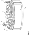
- figure 6 shows a further embodiment of the switching unit with complete, closed coil cassettes 26 which are formed onto the frame part 22 of the switching unit 21.
- stator 27 of an electric motor 28 in each case whose stator teeth and are or are wrapped in a manner not shown with the individual coils of the stator winding.
- FIG figure 8 shows the stator 27 provided with the switching unit 21 according to FIG figure 7 including rotor 29 and motor axis 30 as well as including electronics (printed circuit board) 31 and their contacting with the insulation displacement contacts 1 via their contact heads 5.
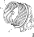
- figure 9 shows the mounted or assembled electric motor 28 as a radiator fan motor for a motor vehicle, including the stator 27, switching unit 21 and fan wheel 34.
Description
- Die Erfindung betrifft einen Schneid-Klemmkontakt für Drähte, insbesondere für die Spulenenden einer Motor- oder Statorwicklung eines Elektromotors, gemäß dem Oberbegriff des Anspruchs 1. Ein derartiger Schenid-Klemmkontakt ist aus der
DE 101 52 006 B4 bekannt. - Ein Schneid-Klemm-Kontakt ist üblicherweise ein Verbindungselement, um ein Stecker-Element mit einem Draht, beispielswiese auch einen mit einer Isolierung versehenen Draht, zu verbinden. Ein derartiger Schneid-Klemm-Kontakt ist üblicherweise für die Schneid-Klemm-Kontaktierung eines einzelnen Drahtes vorgesehen und ausgebildet.
- Ein bürstenloser Elektromotor weist einen Stator mit einer Anzahl von beispielsweise sternförmig angeordneten Statorzähnen auf, welche eine elektrische Statorwicklung (Motorwicklung) in Form einzelner Statorspulen tragen, die ihrerseits aus einem Isolierdraht gewickelt sind. Die Spulen sind mit deren Spulenenden einzelnen Strängen zugeordnet und untereinander in einer vorbestimmten Weise über Verbindungsleiter einer Schalteinheit verschaltet.
- Im Falle eines bürstenlosen Elektromotors als dreiphasige Drehstrommaschine weist der Stator drei Stränge und damit zumindest drei Verbindungsleiter auf, die jeweils phasenversetzt mit elektrischem Strom beaufschlagt werden, um ein magnetisches Drehfeld zu erzeugen, in dem ein üblicherweise mit Permanentmagneten versehener Rotor oder Läufer rotiert. Die Verbindungsleiter werden zur Ansteuerung des Elektromotors an eine Motorelektronik geführt. Die Spulen der Statorwicklung werden mittels der Verbindungsleiter in bestimmter Weise miteinander verschaltet. Die Art der Verschaltung ist durch das Wickelschema der Statorwicklung bestimmt, wobei als Wickelschema eine Sternschaltung oder eine Dreiecksschaltung der Spulen üblich ist.
- Bei einem solchen Elektromotor kann eine Schalteinheit mit einer Anzahl von Kontaktdrähten und mit einem ringförmigen Rahmenteil mit einer Anzahl von geschlitzten Stecktaschen vorgesehen sein. Dabei sind die Kontaktdrähte zu einem Verschaltungsring für die Spulenenden einer Statorwicklung angeordnet. Die Drahtenden der vorzugsweis mit einer isolierenden Ummantelung (Isolierung) versehenen Kontaktdrähte (Kupferdrähte) können mit Schneid-Klemm-Kontakten verbunden sein, d. h. miteinander elektrisch leitend kontaktiert. Der oder jeder Schneid-Klemm-Kontakt weist zwei unter Bildung eines Schneid-Klemm-Schlitzes mit freiendseitiger Schlitzöffnung zueinander beabstandete Schneid-Klemm-Schenkel für ein einzelnes Drahtende auf, wobei die Schneid-Klemm-Kontakte im Montagezustand in Stecktaschen des Rahmenteil der Schalteinheit einsitzen können. Die jeweilige Stecktasche des Rahmenteils kann einen mit dem Schneid-KlemmSchlitz des in diese Stecktasche gesteckten Schneid-Klemm-Kontaktes fluchtenden Schlitz aufweisen.
- Der Erfindung liegt daher die Aufgabe zugrunde, einen besonders geeigneten Schneid-Klemm-Kontakt anzugeben. Der Schneid-Klemm-Kontakt soll insbesondere für die Draht- oder Spulenenden einer Statorwicklung eines Elektromotors geeignet sein.
- Diese Aufgabe wird erfindungsgemäß mit den Merkmalen des Anspruchs 1 gelöst. Vorteilhafte Ausgestaltungen und Weiterbildungen sind Gegenstand der Unteransprüche.
- Der erfindungsgemäße Schneid-Klemm-Kontakt ist zur Verbindung von zwei oder mehreren Drähten (Kupferdrähten) zu einer dauerhaften Verbindung ausgebildet. Der Schneid-Klemm-Schlitz und/oder die Schneid-Klemm-Schenkel des Schneid-Klemm-Kontaktes sind in vorteilhafter Ausgestaltung derart ausgebildet, dass die mindestens zwei in Schlitzlängsrichtung hintereinander in den Schneid-KlemmSchlitz eingeführten und dort an mindestens einer schenkelseitigen Messerkante entlanggeführten Drahtenden sicher klemmkontaktiert sind. Der Schneid-KlemmSchlitz des oder jedes Schneid-Klemm-Kontaktes weist in Schlitzlängsrichtung einen sich an eine schenkelfreiendseitige Schlitzöffnung anschließenden ersten Schlitzbereich mit einer Schneid-Klemm-Kontur und einen sich daran anschließenden, insbesondere rauten- oder rhombusförmig, aufgeweiteten zweiten Schlitzbereich auf.
- Geeigneterweise weist der oder jeder Schenkel des jeweiligen Schneid-Klemm-Kontaktes schenkelaußenseitig mindestens eine erhabene Fügekontur auf.
- Eine geeignete Ausgestaltung sieht zusätzlich oder alternativ vor, dass der Schneid-Klemm-Schlitz des oder jedes Schneid-Klemm-Kontaktes in einem in Schlitzlängsrichtung einer schenkelfreiendseitigen Schlitzöffnung abgewandten Schlitzendbereich eine, vorzugsweise kreisförmige, Ausnehmungskontur aufweist, die eine Sollbiegestelle (Soll-Biegestelle) für die Schneid-Klemm-Schenkel bildet. Gemäß einer zweckmäßigen Weiterbildung dieser Sollbiegestelle der Schneid-Klemm-Schenkel bildet die Ausnehmungskontur eine den Schneid-Klemm-Schlitz verengende Anlagekontur aus, an welcher das in den Schneid-Klemm-Schlitz erste eingeführte Drahtende anschlägt. Dieses Drahtende bildet dann praktisch den Anschlag für das zweite in den Schneid-Klemm-Schlitz eingeführte Drahtende.
- Der Schneid-Klemm-Kontakt weist zwei Schenkel (Schneid-Klemm-Schenkel) auf. Zwischen den Schenkeln ist ein Schlitz (Schneid-Klemm-Schlitz) gebildet, der an den Schenkelfreienden offen und an den gegenüberliegenden Schenkelenden geschlossen ist. Die einander gegenüberliegenden Schenkelkanten sind derart ausgebildet, dass ein von der Schlitzöffnung her in den Schlitz eingeführter Draht (Leiter) an den nachfolgend als Messerkanten bezeichneten Schenkelkanten (umfangsseitig) an- und/oder eingeschnitten und dabei die Drahtisolierung durchtrennt wird. Die biegeelastischen Schenkel üben dabei eine federartige Klemmkraft auf den jeweiligen Draht (das jeweilige Drahtende) aus. Im Schneid-Klemm-Zustand des Drahtes bzw. Drahtendes verlaufen die Messerkanten der Schneid-Klemm-Schenkel quasi tangential zum üblicherweise etwa kreisförmigen Drahtdurchmesser.
- Die Schneiden- beziehungsweise Messerkanten- und/oder die Schlitzgeometrie des Schneid-Klemm-Kontaktes ist dabei derart, dass in Schlitzlängsrichtung sowohl ein erster als auch mindestens ein zweiter Draht (Drahtende) im Schneid-Klemm- Schlitz desselben Schneid-Klemm-Kontaktes zuverlässig klemmkontaktiert wird.
- Insbesondere ist dabei ein bestimmtes, vorgegebenes und/oder gewähltes Verhältnis der Schnitttiefe des Drahtes (Drahtendes) zum Drahtdurchmesser mittels der Messerkantenanordnung und/oder -kontur hergestellt. Die Geometrie beziehungsweise Messerkantenkontur und/oder Schlitzgeometrie ist dabei derart, dass zunächst ein erster Draht (Drahtende) beim Kontaktieren in den Schneid-KlemmKontakt hineingedrückt und an der Messerkante beziehungsweise den beiden den Schlitz flankierenden Messerkanten angeschnitten wird. Der Draht ist dabei normal zur Schlitzebene des Schneid-Klemm-Kontaktes orientiert. Im Bereich der Schneid-Klemm-Kanten verringert sich der Drahtdurchmesser um beispielsweise 20% bis 25% während der nachfolgend beim Kontaktieren angeschnittene Draht hinsichtlich dessen Drahtdurchmessers im Bereich der Schneidkanten um einen geringeren Betrag von beispielsweise 10% bis < 20% angeschnitten wird. Der oder jeder Draht ist dabei normal zur Schlitzebene des Schneid-Klemm-Kontaktes orientiert.
- Die Schlitzgeometrie ist derart, dass ausgehend von der Schlitzöffnung sich an diese zunächst ein vergleichsweise kurzer, erster Schneidbereich und an diesen ein erweiterter zweiter Bereich sowie an diesen wiederum ein vergleichsweise langer, dritter Schneidbereich anschließt. Der aufgeweitete Bereich ist vorteilhafterweise rautenförmig, indem in die beiden gegenüberliegenden Schenkel in diese jeweils eine etwa V-förmige Einklinkung eingebracht ist. Da der Schneid-KlemmKontakt vorzugsweise ein Stanzteil ist, ist sowohl diese Geometrie als auch eine andere, den aufgeweiteten Bereich darstellende Geometrie beziehungsweise Kontur denkbar. Im aufgeweiteten Bereich müssen die einander zugewandten Kanten der Schenkel nicht unbedingt als Messerkanten ausgeführt sein.
- Vorzugsweise gegenüberliegend zu diesem aufgeweiteten Bereich sind geeigneterweise an die Schneid-Klemm-Schenkel außenseitig lokale erhabene Konturen angeformt. Zweckmäßigerweise sind zudem außenseitig entlang der Schneid-Klemm-Schenkel weitere Fügekonturen (Zapfen und/oder Nuten) angeformt bzw. stanztechnisch eingebracht.
- Der aufgeweitete Bereich des Schlitzes hat den vorteilhaften Zweck und die geeignete Funktion, den zunächst (ersten) im Schlitz angeschnittenen Draht aufzunehmen, sobald der weitere (zweite) Draht in dem sich an die Einführöffnung des Schlitzes anschließenden, vergleichsweise kurzen oder schmalen Schneidbereich zwischen den Messerkanten der einander gegenüber angeordneten Schenkel gelangt. Da sich in dieser Position der erste Draht in dem aufgeweiteten Bereich des Schlitzes befindet, wirken in dem zur Schlitzöffnung hin vorgelagerten Schneidbereich die erforderlichen Schneid-Klemm-Kräfte der beiden Schenkel auf den zweiten Draht. Auf diese Weise werden nacheinander beide Drähte angeschnitten und können anschließend über den erweiterten Bereich in den sich daran anschließenden Schneid-Klemm-Bereich, der insbesondere als Klemmbereich wirksam ist, klemmkontaktierend in Schlitzlängsrichtung weitergeführt beziehungsweise weitergepresst werden.
- Gemäß einer weiteren vorteilhaften Ausgestaltung wirkt der Schneid-KlemmKontakt mit einer an dessen Außenkontur, insbesondere im Bereich dessen Schenkeln, angepassten Aufnahmetasche zusammen. Diese ist geeigneterweise ebenfalls geschlitzt, wobei einander gegenüberliegende taschenseitige Schlitze im Montagezustand des Schneid-Klemm-Kontaktes mit dessen Schlitz fluchten. Die außenseitig an den Schneid-Klemm-Kontakt angeformten Fügekonturen ermöglichen einen festen kraft- und/oder formschlüssigen Sitz des Schneid-Klemm-Kontaktes innerhalb der Füge- oder Aufnahmetasche, so dass vorzugsweise über die Schenkel eine zuverlässige und/oder zusätzliche Kraft auf den oder jeden kontaktierten Draht ausgeübt wird. In dieser Steck- oder Aufnahmetasche können in deren Schlitzbereichen die zu kontaktierenden Drähte bereits eingelegt sein, wenn der Schneid-Klemm-Kontakt in diese Fügetasche des zusätzlichen Teils eingepresst wird. Alternativ kann auch der mit den beiden Drähten bereits schneid-klemm-kontaktierte Kontakt anschließend in die Tasche eingesteckt werden.
- Vorteilhafterweise ist die oder jede Fügetasche Bestandteil eines (ringförmigen) Rahmenteils einer Schalteinheit zur schaltungstechnisch vorgegebenen Kontaktierung von Kontaktdrähten, Spulenenden und/oder Phasenanschlüssen für die Stator- beziehungsweise Motorwicklung eines Elektromotors, insbesondere eines Kühlerlüftermotors eines Kraftfahrzeugs.
- Hinsichtlich der Schalteinheit für einen, vorzugsweise bürstenlosen, Elektromotor, mit einer Anzahl von Kontaktdrähten zur Verschaltung von Spulen einer Statoroder Motorwicklung bilden die Schneid-Klemm-Kontaktes geeigneterweise eine entsprechende Anzahl von Phasenanschlüssen, beispielsweise drei Phasenanschlüsse bei einem dreiphasigen Elektromotor bzw. einer dreiphasigen Motorwicklung. Dabei können die mittels der Schneid-Klemm-Kontakte hergestellten Verbindungen der Drahtenden der vorzugsweise zu einem Verschaltungsring angeordneten Kontaktdrähte auch für die Phasenanschlüsse einer mehrphasigen Motoroder Statorwicklung eingesetzt oder verwendet werden.
- Zur Kontaktierung von phasenseitigen Anschlüssen sind beispielsweise drei derartige Schneid-Klemm-Kontakte mit diesen zugeordneten Füge- oder Stecktaschen im Rahmenteil der Schalteinheit (Verschaltungs- oder Terminationsring) vorgesehen und beispielsweise zueinander äquidistant angeordnet. Das vorzugsweise kreisringförmige Rahmenteil nimmt zudem geeigneterweise zur Verschaltung der Spulen der Statorwicklung vorgesehene Kontaktdrähte auf, die mit den jeweiligen Spulenenden und/oder Phasenanschlüssen kontaktiert werden.
- Nachfolgend werden Ausführungsbeispiele der Erfindung anhand einer Zeichnung näher erläutert. Darin zeigen:
- Fig. 1a und 1b
- einen Schneid-Klemm-Kontakt mit einem von zwei Schneid-Klemm-Schenkeln flankierten Schneid-Klemm-Schlitz ohne bzw. mit schenkelaußenseitig einer Schlitzöffnung angeordneter Fügekontur,
- Fig. 2
- einen der Schneid-Klemm-Schenkel eines Schneid-Klemm-Kontakts mit einer eine Soll-Biegestelle herstellenden, kreisförmigen Ausnehmung im Schenkel-Übergangsbereich,
- Fig. 3
- in perspektivischer Darstellung einen Verschaltungsring mit mehreren in Kreisform angeordneten Kontaktdrähten und drei äquidistant angeordneten Schneid-Klemm-Kontakten,
- Fig. 4
- in einer Darstellung gemäß
Figur 3 eine Schalteinheit mit einem derartigen Verschaltungsring und mit einem ringförmigen Rahmenteil, - Fig. 5
- die Schalteinheit gemäß
Figur 4 ohne Verschaltungsring und mit Blick auf eine Stecktasche ohne eingesetzten Schneid-Klem m-Kontakt, - Fig. 6
- in einer Darstellung gemäß
Fig. 5 eine Ausführungsform der Schalteinheit mit geschlossenen Spulenkassetten - Fig. 7
- in perspektivischer Darstellung einen Stator mit aufgesetzter Schalteinheit,
- Fig. 8
- in perspektivischer Darstellung den Stator mit aufgesetzter Schalteinheit und den Rotor sowie die mit den Schneid-Klemm-Kontakten verbundene Elektronik (Leiterplatte) eines Elektromotors, und
- Fig. 9
- in perspektivischer Darstellung den Elektromotor als Kühlerlüftermotor für ein Kraftfahrzeugs inklusive Schalteinheit und Elektronik.
- Die
Figuren 1a und 1b zeigen einen nachfolgend auch einfach als Kontakt bezeichneten Schneid-Klemm-Kontakt 1 mit einem nachfolgend einfach als Schlitz 2 bezeichneten Schneid-Klemm-Schlitz, der von zwei nachfolgend einfach als Schenkel 3 des bezeichneten Schneid-Klemm-Schenkeln des Schneid-Klemm-Kontaktes 1 flankiert ist, sich also zwischen diesen beiden Schenkeln 3 befindet bzw. gebildet ist. Der Kontakt 1 ist vorzugsweis ein Stanzteil. Die Schenkel 3 des Kontaktes 1 gehen in einen vorzugsweise mit einer Durchgangsöffnung (Durchgangsbohrung) 4 versehenen Kontaktkopf 5 über. Außenseitig der Schenkel 3 sind an diese Fügekonturen 6 (Nuten, Zapfen) angeformt beziehungsweise eingestanzt. - Der Schlitz 2 weist im Bereich der Schenkelfreienden der Schenkel 3 eine Schlitzöffnung 7 auf. An diesen schließt sich in Schlitzlängsrichtung 8 eine erste, vergleichsweise kurze Schneid-Klemm-Kontur 9 an. Diese geht in Schlitzlängsrichtung 8 in einen erweiterten Bereich 10 über. Dieser ist vorzugsweise rautenförmig. An diesen Bereich 10 wiederum schließt sich ein weiterer, vergleichsweise langer Schneid-Klemm-Bereich zumindest aber ein Klemmbereich 11 an. Dieser endet an den den Schenkelfreienden gegenüberliegenden Enden, d. h. am Übergangsbereich 12 der Schenkel 3.
- Aufgrund dieser Kontaktgeometrien ist eine zuverlässige Kontaktierung beziehungsweise Verbindung nicht nur eines Drahtes, sondern zweier oder mehrere Drähte ermöglicht. Diese werden aufeinanderfolgend in Schlitzlängsrichtung 8 in den Schlitz 2 eingeführt beziehungsweise eingepresst und dabei umfangsseitig (azimutal) angeschnitten. Die Schnitttiefe ist dabei größer oder gleich der Dicke einer Isolierung (isolierenden Ummantelung) des oder jedes Drahtes. Hierzu sind die einander zugewandten Schenkelkanten der Schenkel 3 im Bereich des Schlitzes 2 messerartig als Messerkanten 13 ausgeführt. Die Durchmesserreduzierung des ersten im Schlitz 2 angeschnittenen Drahtes beträgt beispielsweise etwa 22%, während die Durchmesserreduzierung des weiteren im Schlitz 2 angeschnittenen Drahtes beispielsweise etwa 16% beträgt, bezogen auf einen Kupferdraht mit einem Durchmesser von beispielsweise 1,12 mm und einer Drahtisolierung von beispielsweise 0,003 mm, also einem Gesamtdrahtdurchmesser von ca. 1,15 mm bis 1,16 mm.
- Bei der in
Fig. 2 dargestellten Ausführungsform des Schneid-Klemm-Kontaktes 1, von dem lediglich der linke Schneid-Klemm-Schenkel 3 dargestellt ist, weist der rautenförmige Bereich 10 auf der der Schlitzöffnung 7 zugewandten Seite eine spitz zulaufende, vergleichsweise ausgeprägte Schneidkontur 10a auf. Im oder am Übergangsbereich 12 der Schenkel 3 ist eine im Ausführungsbeispiel kreisrunde Ausnehmungskontur 12a vorgesehen. Diese führt zu einer zumindest geringfügigen Verringerung der Schenkelbreite b der Schenkel 3 im Vergleich zur Schenkelbreite der Schneid-Klemmkontakte 1 gemäß denFiguren 1a und 1b ohne derartige Ausnehmungskontur im Übergangsbereich 12. - Diese Ausnehmungskontur 12a definiert eine Soll-Biegestelle 12b für die Schenkel 3, wenn diese bei Einführen der mit 20 bezeichneten Drähte oder Drahtenden in den Schneid-Klemmschlitz 2 des Kontaktes 1 nach außen ausbiegen. Die Ausnehmungskontur 12a bildet zudem eine den Schneid-Klemm-Schlitz 2 verengende Anlagekante 12c, beispielsweise in Form eines sektorförmigen Überstandes, als schlitzinterner Anschlag für die Drahtenden 20.
-
Figur 3 zeigt einen Verschaltungsring 18 mit mehreren in Kreisform angeordneten Kontaktdrähten 19 und drei äquidistant angeordneten Schneid-Klemm-Kontakten 1, die jeweils zwei Drähte beziehungsweise Drahtenden 20 schneid-klemm-kontaktieren. -
Figur 4 zeigt eine Schalteinheit 21 mit einem derartigen Verschaltungsring 18. Die Schalteinheit 21 weist einen ringförmigen Rahmenkörper (Rahmenteil) 22, vorzugsweise aus Kunststoff, auf. Dieser wiederum weist im Bereich des jeweiligen Schneid-Klemm-Kontaktes 1 eine Aufnahmetasche (Steck-/Fügetasche) 23 zur Aufnahme des Schneid-Klemm-Kontaktes 1 auf. -
Figur 5 zeigt die Schalteinheit 21 beziehungsweise das Rahmenteil 22 gemäß Figur 4 mit zwei in die zugeordnete Stecktaschen 23 eingesetzten Schneid-Klemm-Kontakten 1, während die im Figurenvordergrund erkennbare Stecktasche 23 ohne Schneid-Klemm-Kontakt 1 erkennbar ist. Die in diese Stecktaschen 23 eingebrachten, endseitig wiederum mit einer Schlitzöffnung 24 versehenen Schlitze 25 fluchten mit dem Schlitz 2 des jeweiligen Schneid-Klemm-Kontaktes 1. Dabei befindet sich die jeweilige rahmenseitige Schlitzöffnung 24 auf der der Schlitzöffnung 7 des Schneid-Klemm-Kontaktes 1gegenüberliegenden Schlitzseite, also auf der Einführ- oder Einsteckseite der jeweiligen Stecktasche 23. - Wie in den
Figuren 3 und 4 erkennbar ist, verlaufen die kontaktierten Drahtenden 20 normal zur vom Schlitz 2 aufgespannten Schlitzebene. -
Figur 6 zeigt eine weitere Ausführungsform der Schalteinheit mit vollständigen, geschlossenen Spulenkassetten 26, die an das Rahmenteil 22 der Schalteinheit 21 angeformt sind. Diese nehmen im Montagezustand des inFigur 7 gezeigten Stators 27 eines Elektromotors 28 jeweils dessen Statorzähne auf und sind beziehungsweise werden in nicht näher dargestellter Art und Weise mit den einzelnen Spulen der Statorwicklung umwickelt. -
Figur 8 zeigt den mit der Schalteinheit 21 versehenen Stator 27 gemäßFigur 7 inklusive Rotor 29 und Motorachse 30 sowie inklusive Elektronik (Leiterplatte) 31 sowie deren Kontaktierung mit den Schneid-Klemm-Kontakten 1 über deren Kontaktköpfe 5. Diese sind in beispielsweise crimplaschenartige Stecktaschen 32 von beispielsweise als Stanz-Biegeteile aus Flachdraht hergestellten Kontakten (Flachkontakten) oder Kontaktabschnitten 33 eingesteckt und bilden hierbei die Phasenanschlüsse zur dreiphasigen Bestromung der Stator- bzw. Motorwicklung. -
Figur 9 zeigt den montierten beziehungsweise zusammengesetzten Elektromotor 28 als Kühlerlüftermotor für ein Kraftfahrzeugs inklusive Stator 27, Schalteinheit 21 und Lüfterrad 34. -
- 1
- Schneid-Klemm-Kontakt
- 2
- Schneid-Klemm-Schlitz
- 3
- Schneid-Klemm-Schenkel
- 4
- Durchgangsöffnung/-bohrung
- 5
- Kontaktkopf
- 6
- Fügekontur
- 7
- Schlitzöffnung
- 8
- Schlitzlängsrichtung
- 9
- Schneid-Klemm-Kontur
- 10
- Bereich
- 11
- Schneid-Klemm-Bereich
- 12
- Übergangsbereich
- 12a
- Ausnehmungskontur
- 12b
- Soll-Biegestelle
- 12c
- Anlagekante/Anschlag
- 13
- Messerkante
- 18
- Verschaltungsring
- 19
- Kontaktdraht
- 20
- Draht/Drahtende
- 21
- Schalteinheit
- 22
- Rahmenteil/-körper
- 23
- Aufnahme-/Steck-/Fügetasche
- 24
- Schlitzöffnung
- 25
- Schlitz
- 26
- Spulenkassette
- 27
- Stator
- 28
- Elektromotor
- 29
- Rotor
- 30
- Motorachse
- 31
- Elektronik/Leiterplatte
- 32
- Stecktasche
- 33
- Kontakt/-abschnitt
- 34
- Lüfterrad
Claims (5)
- Schneid-Klemm-Kontakt (1) zum Verbinden mindestens zweier Drähte oder Drahtenden (20), mit zwei unter Bildung eines Schneid-Klemm-Schlitzes (2) zueinander beabstandeten Schneid-Klemm-Schenkeln (3),- wobei der Schneid-Klemm-Schlitz (2) und/oder die Schneid-Klemm-Schenkel (3) des Schneid-Klemm-Kontaktes (1) derart ausgebildet ist bzw. sind, dass die mindestens zwei in Schlitzlängsrichtung (8) hintereinander in den Schneid-Klemm-Schlitz (2) eingeführten und dort an mindestens einer schenkelseitigen Messerkante (13) entlanggeführten Drahtenden (20) sicher klemmkontaktiert sind,
dadurch gekennzeichnet,- dass der Schneid-Klemm-Schlitz (2) des Schneid-Klemm-Kontaktes (1) in Schlitzlängsrichtung (8) eine schenkelfreiendseitige Schlitzöffnung (7) und eine sich an die Schlitzöffnung (7) anschließende, vergleichsweise kurze Schneid-Klemm-Kontur (9) aufweist, die in Schlitzlängsrichtung (8) in einen rautenförmig aufgeweiteten Schlitzbereich (10) übergeht, an den sich ein weiterer, vergleichsweise langer Schneid-Klemm- oder Klemm-Bereich (11) anschließt,- dass der aufgeweitete Schlitzbereich (10) auf der der Schlitzöffnung (7) zugewandten Seite eine spitz zulaufende, vergleichsweise ausgeprägte Schneidkontur (10a) aufweist, und- dass der aufgeweitete Schlitzbereich (10) dazu vorgesehen und eingerichtet ist, dass zunächst im Schneid-Klemm-Schlitz (2) angeschnittene erste Drahtende (20) aufzunehmen, sobald das zweite Drahtende (20) in den sich an die Schlitzöffnung (7) anschließenden ersten Schlitzbereich zwischen die Messerkanten der Schneid-Klemm-Kontur (9) der einander gegenüber angeordneten Schneid-Klemm-Schenkel (3) gelangt. - Schneid-Klemm-Kontakt (1) nach Anspruch 1, wobei der Schneid-Klemm-Schlitz (2) des Schneid-Klemm-Kontaktes (1) in einem in Schlitzlängsrichtung (8) der schenkelfreiendseitigen Schlitzöffnung (7) abgewandten Schlitzendbereich (11) eine Ausnehmungskontur (12a) aufweist, die eine Sollbiegestelle für die Schneid-Klemm-Schenkel (3) bildet.
- Schneid-Klemm-Kontakt (1) nach Anspruch 2, wobei die Ausnehmungskontur (12a) kreisförmige ist.
- Schneid-Klemm-Kontakt (1) nach Anspruch 2 oder 3, wobei die als Sollbiegestelle dienende Ausnehmungskontur (12a) eine den Schneid-KlemmSchlitz (2) verengende Anlagekontur (12c) als Anschlag für das oder jedes Drahtende (20) ausbildet.
- Schneid-Klemm-Kontakt (1) nach einem der Ansprüche 1 bis 4, wobei der oder jeder Schenkel (3) des jeweiligen Schneid-Klemm-Kontaktes (1) schenkelaußenseitig mindestens eine erhabene Fügekontur (6) aufweist.
Applications Claiming Priority (3)
| Application Number | Priority Date | Filing Date | Title |
|---|---|---|---|
| DE102015001214 | 2015-02-03 | ||
| PCT/EP2016/052267 WO2016124636A1 (de) | 2015-02-03 | 2016-02-03 | Elektromotor und schalteinheit hierfür |
| EP16705443.6A EP3254357A1 (de) | 2015-02-03 | 2016-02-03 | Elektromotor und schalteinheit hierfür |
Related Parent Applications (1)
| Application Number | Title | Priority Date | Filing Date |
|---|---|---|---|
| EP16705443.6A Division EP3254357A1 (de) | 2015-02-03 | 2016-02-03 | Elektromotor und schalteinheit hierfür |
Publications (2)
| Publication Number | Publication Date |
|---|---|
| EP3402047A1 EP3402047A1 (de) | 2018-11-14 |
| EP3402047B1 true EP3402047B1 (de) | 2023-04-05 |
Family
ID=55404681
Family Applications (2)
| Application Number | Title | Priority Date | Filing Date |
|---|---|---|---|
| EP18168825.0A Active EP3402047B1 (de) | 2015-02-03 | 2016-02-03 | Schneid-klemm-kontakt |
| EP16705443.6A Pending EP3254357A1 (de) | 2015-02-03 | 2016-02-03 | Elektromotor und schalteinheit hierfür |
Family Applications After (1)
| Application Number | Title | Priority Date | Filing Date |
|---|---|---|---|
| EP16705443.6A Pending EP3254357A1 (de) | 2015-02-03 | 2016-02-03 | Elektromotor und schalteinheit hierfür |
Country Status (5)
| Country | Link |
|---|---|
| US (2) | US10396616B2 (de) |
| EP (2) | EP3402047B1 (de) |
| KR (2) | KR102055213B1 (de) |
| CN (2) | CN107210641B (de) |
| WO (1) | WO2016124636A1 (de) |
Families Citing this family (26)
| Publication number | Priority date | Publication date | Assignee | Title |
|---|---|---|---|---|
| DE102016226200A1 (de) * | 2016-12-23 | 2018-06-28 | Bühler Motor GmbH | Bürstenloser Motor |
| JP2018125951A (ja) * | 2017-01-31 | 2018-08-09 | 日本電産株式会社 | モータ及びそれを備えた送風装置 |
| DE102017209621A1 (de) * | 2017-06-08 | 2018-12-13 | Robert Bosch Gmbh | Antriebseinheit mit einem elektronisch kommutierten Motor und einer Elektronikeinheit |
| JP2019022327A (ja) * | 2017-07-18 | 2019-02-07 | 株式会社ケーヒン | 空調用ブロアモータユニット |
| DE102017212995A1 (de) | 2017-07-27 | 2019-01-31 | Brose Fahrzeugteile GmbH & Co. Kommanditgesellschaft, Würzburg | Verfahren zum Montieren einer Schalteinheit an einer Komponente eines Elektromotors |
| DE102017216084A1 (de) * | 2017-09-12 | 2019-03-14 | Robert Bosch Gmbh | Stator für eine elektrische Maschine, eine elektrische Maschine und Verfahren zum Herstellen eines solchen Stators |
| DE102017216807A1 (de) * | 2017-09-22 | 2019-03-28 | Robert Bosch Gmbh | Pumpeneinrichtung mit einem Kontaktierelement |
| DE102017222076A1 (de) * | 2017-12-06 | 2019-06-06 | Brose Fahrzeugteile GmbH & Co. Kommanditgesellschaft, Würzburg | Elektromotor sowie Schalteinheit hierfür |
| CN110149032B (zh) * | 2018-02-12 | 2021-06-18 | 比亚迪股份有限公司 | 电机总成和具有其的车辆 |
| DE112019002361A5 (de) | 2018-05-08 | 2021-01-21 | Brose Fahrzeugteile SE & Co. Kommanditgesellschaft, Würzburg | Stator einer elektrischen Maschine und elektrische Maschine sowie Verschaltungseinrichtung |
| DE202018102652U1 (de) * | 2018-05-11 | 2019-08-14 | Brose Fahrzeugteile GmbH & Co. Kommanditgesellschaft, Würzburg | Stator für einen Elektromotor und Elektromotor sowie Schalteinheit |
| EP3651320B1 (de) * | 2018-11-12 | 2022-05-11 | Otis Elevator Company | Wicklungskopf |
| JP7183799B2 (ja) * | 2019-01-09 | 2022-12-06 | 株式会社デンソー | 電気接続装置 |
| DE102019104706A1 (de) * | 2019-02-25 | 2020-08-27 | Nidec Gpm Gmbh | Elektrische Kontaktierung von Statoranschlüssen auf einer Leiterplatte mittels horizontal ausgerichteten Schneidklemmkontakten |
| EP3949084A1 (de) * | 2019-03-28 | 2022-02-09 | Eldor Corporation S.p.A. | Schaltvorrichtung für einen elektromotor und elektromotor mit dieser schaltvorrichtung |
| DE102019121184A1 (de) * | 2019-08-06 | 2021-02-11 | Schaeffler Technologies AG & Co. KG | Elektrische Maschine |
| CN112531948A (zh) * | 2019-09-18 | 2021-03-19 | 泰科电子(上海)有限公司 | 线圈骨架和定子骨架 |
| KR102241110B1 (ko) * | 2019-12-05 | 2021-04-19 | 주식회사 코아비스 | 모터 및 이를 포함한 전동식 펌프 |
| DE102020203875A1 (de) * | 2020-01-24 | 2021-07-29 | Brose Fahrzeugteile SE & Co. Kommanditgesellschaft, Würzburg | Kontaktvorrichtung eines Stators |
| DE102020113551A1 (de) * | 2020-05-19 | 2021-11-25 | Fte Automotive Gmbh | Antriebsaggregat |
| CN117060610A (zh) * | 2020-07-24 | 2023-11-14 | 安徽威灵汽车部件有限公司 | 定子、电机、流体泵和车辆 |
| TWI750823B (zh) * | 2020-09-25 | 2021-12-21 | 大陸商深圳興奇宏科技有限公司 | 風扇定子結構 |
| TWI739609B (zh) * | 2020-09-25 | 2021-09-11 | 大陸商深圳興奇宏科技有限公司 | 風扇定子結構製造方法 |
| US11894735B2 (en) | 2020-10-08 | 2024-02-06 | Asia Vital Components (China) Co., Ltd. | Manufacturing method of fan stator structure |
| DE102021207552A1 (de) * | 2021-07-15 | 2023-01-19 | Bühler Motor GmbH | Stator für eine elektrische Antriebseinheit und Verfahren zur Herstellung eines Stators für eine elektrische Antriebseinheit |
| WO2024026719A1 (zh) * | 2022-08-03 | 2024-02-08 | 德昌电机(江门)有限公司 | 导电连接座、定子组件及马达 |
Family Cites Families (26)
| Publication number | Priority date | Publication date | Assignee | Title |
|---|---|---|---|---|
| US3950062A (en) | 1974-07-23 | 1976-04-13 | Amp Incorporated | Wire slot terminal double beam system |
| FR2419594A1 (fr) | 1978-03-07 | 1979-10-05 | Nozick Jacques | Element de contact electrique a connexion auto-denudante pour fil ou cable |
| US4287446A (en) | 1979-06-27 | 1981-09-01 | Amp Incorporated | Stator for stepper motor |
| US5088934A (en) | 1991-02-20 | 1992-02-18 | Chian Chyun Enterprise Co. Ltd. | Electrical terminal |
| DE4340032C1 (de) * | 1993-11-24 | 1994-09-01 | Hella Kg Hueck & Co | Elektrischer Verbinder |
| KR0113849Y1 (ko) | 1994-05-07 | 1998-04-15 | 안영숙 | 슬롯형 단자 및 슬롯형 단자를 구비한 단자 블록 |
| US5975919A (en) | 1997-08-26 | 1999-11-02 | Lucent Technologies Inc. | Terminal housing and wire board arrangement with solderless mountable insulation displacement connector terminals |
| US6123566A (en) * | 1998-12-21 | 2000-09-26 | Lucent Technologies Inc. | Terminal strip with integrated strain relief mechanism for an insulation displacement connector |
| JP2002151189A (ja) * | 2000-11-08 | 2002-05-24 | Yazaki Corp | 配線接続コネクタ |
| DE10129615A1 (de) | 2001-06-20 | 2003-01-02 | Delphi Tech Inc | Elektrischer Verbinder |
| DE10152006B4 (de) * | 2001-10-22 | 2011-06-01 | Zf Sachs Ag | Stator für eine elektrische Maschine |
| DE10261611A1 (de) | 2002-12-27 | 2004-07-08 | Robert Bosch Gmbh | Verschaltelement für eine Wicklung einer elektrischen Maschine |
| US7135799B2 (en) | 2003-03-19 | 2006-11-14 | Pacsci Motion Control, Inc. | Method for winding a stator of multi-phase motors |
| DE10324664A1 (de) * | 2003-05-30 | 2004-12-30 | Siemens Ag | Rollen und Rollenmotoren |
| DE50313509D1 (de) | 2003-10-22 | 2011-04-14 | Brose Fahrzeugteile | Verschaltungseinheit für einen Stator eines Elektromotors |
| JP4697403B2 (ja) * | 2005-04-14 | 2011-06-08 | 株式会社ジェイテクト | コネクタ付きモータ |
| JP5333996B2 (ja) * | 2007-08-17 | 2013-11-06 | 株式会社安川電機 | 固定子およびこれを用いた回転電機 |
| FR2923951B1 (fr) | 2007-11-19 | 2009-11-27 | Sonceboz Automotive Sa | Ensemble de connexion electrique pour moteur sans balai. |
| DE102008033905A1 (de) * | 2008-07-18 | 2010-01-21 | Wago Verwaltungsgesellschaft Mbh | Leiteranschlusselement |
| US8418346B2 (en) | 2008-09-16 | 2013-04-16 | Surtec Industries Inc. | Wire termination tool and RJ jack for use therewith |
| US7736173B2 (en) * | 2008-09-16 | 2010-06-15 | Surtec Industries, Inc. | Insulation displacement contact (IDC) and IDC mounting system |
| TWM368223U (en) * | 2009-04-20 | 2009-11-01 | Surtec Ind Inc | A combination of the insulation displacement contact (IDC) and the connector housing |
| DE102009036128A1 (de) | 2009-08-05 | 2011-02-10 | Brose Fahrzeugteile Gmbh & Co. Kg, Hallstadt | Elektrische Komponente eines Kraftfahrzeugs |
| JP5884829B2 (ja) | 2011-10-14 | 2016-03-15 | オムロン株式会社 | 板状端子 |
| ITTO20120820A1 (it) * | 2012-09-21 | 2014-03-22 | Schneider Electric Ind Sas | Gruppo porta-contatti per una presa/spina di connessione elettrica |
| DE102014220201A1 (de) * | 2014-10-06 | 2016-04-07 | Bühler Motor GmbH | Elektronisch kommutierter Gleichstrommotor, insbesondere für eine Ölpumpe |
-
2016
- 2016-02-03 KR KR1020187025496A patent/KR102055213B1/ko active IP Right Grant
- 2016-02-03 EP EP18168825.0A patent/EP3402047B1/de active Active
- 2016-02-03 EP EP16705443.6A patent/EP3254357A1/de active Pending
- 2016-02-03 CN CN201680008381.5A patent/CN107210641B/zh active Active
- 2016-02-03 CN CN201810449757.7A patent/CN108512335B/zh active Active
- 2016-02-03 KR KR1020177024705A patent/KR101943478B1/ko active IP Right Grant
- 2016-02-03 WO PCT/EP2016/052267 patent/WO2016124636A1/de active Application Filing
-
2017
- 2017-08-03 US US15/667,813 patent/US10396616B2/en active Active
-
2018
- 2018-04-25 US US15/962,040 patent/US10468932B2/en active Active
Also Published As
| Publication number | Publication date |
|---|---|
| CN108512335A (zh) | 2018-09-07 |
| KR102055213B1 (ko) | 2019-12-12 |
| EP3254357A1 (de) | 2017-12-13 |
| CN107210641A (zh) | 2017-09-26 |
| CN108512335B (zh) | 2020-06-05 |
| CN107210641B (zh) | 2019-10-08 |
| US20180241273A1 (en) | 2018-08-23 |
| US20170331342A1 (en) | 2017-11-16 |
| US10396616B2 (en) | 2019-08-27 |
| US10468932B2 (en) | 2019-11-05 |
| KR101943478B1 (ko) | 2019-01-29 |
| WO2016124636A1 (de) | 2016-08-11 |
| EP3402047A1 (de) | 2018-11-14 |
| KR20180100733A (ko) | 2018-09-11 |
| KR20170113635A (ko) | 2017-10-12 |
Similar Documents
| Publication | Publication Date | Title |
|---|---|---|
| EP3402047B1 (de) | Schneid-klemm-kontakt | |
| EP3682530B1 (de) | Stator für eine elektrische maschine, eine elektrische maschine und verfahren zum herstellen eines solchen stators | |
| DE102015200089B4 (de) | Stator für eine elektrische Maschine und Verfahren zum Herstellen eines solchen | |
| EP1526628B1 (de) | Verschaltungseinheit für einen Stator eines Elektromotors | |
| EP0777312B1 (de) | Stator mit Verschaltungsanordnung für Elektromotoren | |
| EP3320600B1 (de) | Statoranorndung, elektrische drehstrommaschine und verfahren zum herstellen einer statoranordnung | |
| EP2082472B1 (de) | Elektromotor | |
| DE112013006336B4 (de) | Verbindungsanschluss, Verbindungsanschlusseinheit und Motor | |
| DE10152006B4 (de) | Stator für eine elektrische Maschine | |
| DE112019006919B4 (de) | Stator und Elektromotor | |
| DE102015225088A1 (de) | Motor und Verfahren zum Herstellen desselben | |
| EP3170245B1 (de) | Stator eines elektromotors | |
| DE102015208210B4 (de) | Elektronisch kommutierter Gleichstrommotor | |
| DE202015008207U1 (de) | Stator eines Elektromotors sowie Schalteinheit hierfür | |
| DE102017206187B4 (de) | Motor mit Verdrahtungsplatte, die durch Verbinden einer Wicklung durch Crimpen ausgebildet wird | |
| WO2019110420A1 (de) | Elektromotor sowie schalteinheit hierfür | |
| DE202014010565U1 (de) | Stator eines Elektromotors mit einer Verschaltungseinheit | |
| EP1997215B1 (de) | Elektrische maschine | |
| EP3724971A1 (de) | Statoranordnung mit wicklungsanordnung | |
| DE102019107762A1 (de) | Stator für eine rotierende elektrische maschine, rotierendeelektrische maschine; und verfahren zur herstellung eines statorsfür eine rotierende elektrische maschine | |
| EP1603216B1 (de) | Bürstenloser Elektromotor und Verfahren zur Herstellung desselben | |
| DE102021214766A1 (de) | Stator für eine elektrische Maschine, eine elektrische Maschine und Verfahren zum Herstellen eines solchen Stators | |
| DE112021006860T5 (de) | Kompakte Sammelschienenanordnung | |
| DE102012014218A1 (de) | Kommutator einer elektrischen Maschine | |
| DE102022200865A1 (de) | Stator eines Elektromotors |
Legal Events
| Date | Code | Title | Description |
|---|---|---|---|
| PUAI | Public reference made under article 153(3) epc to a published international application that has entered the european phase |
Free format text: ORIGINAL CODE: 0009012 |
|
| STAA | Information on the status of an ep patent application or granted ep patent |
Free format text: STATUS: THE APPLICATION HAS BEEN PUBLISHED |
|
| AC | Divisional application: reference to earlier application |
Ref document number: 3254357 Country of ref document: EP Kind code of ref document: P |
|
| AK | Designated contracting states |
Kind code of ref document: A1 Designated state(s): AL AT BE BG CH CY CZ DE DK EE ES FI FR GB GR HR HU IE IS IT LI LT LU LV MC MK MT NL NO PL PT RO RS SE SI SK SM TR |
|
| STAA | Information on the status of an ep patent application or granted ep patent |
Free format text: STATUS: REQUEST FOR EXAMINATION WAS MADE |
|
| 17P | Request for examination filed |
Effective date: 20190514 |
|
| RBV | Designated contracting states (corrected) |
Designated state(s): AL AT BE BG CH CY CZ DE DK EE ES FI FR GB GR HR HU IE IS IT LI LT LU LV MC MK MT NL NO PL PT RO RS SE SI SK SM TR |
|
| RAP1 | Party data changed (applicant data changed or rights of an application transferred) |
Owner name: BROSE FAHRZEUGTEILE SE & CO. KOMMANDITGESELLSCHAFT, WUERZBURG |
|
| TPAC | Observations filed by third parties |
Free format text: ORIGINAL CODE: EPIDOSNTIPA |
|
| STAA | Information on the status of an ep patent application or granted ep patent |
Free format text: STATUS: EXAMINATION IS IN PROGRESS |
|
| 17Q | First examination report despatched |
Effective date: 20210604 |
|
| STAA | Information on the status of an ep patent application or granted ep patent |
Free format text: STATUS: EXAMINATION IS IN PROGRESS |
|
| GRAP | Despatch of communication of intention to grant a patent |
Free format text: ORIGINAL CODE: EPIDOSNIGR1 |
|
| STAA | Information on the status of an ep patent application or granted ep patent |
Free format text: STATUS: GRANT OF PATENT IS INTENDED |
|
| INTG | Intention to grant announced |
Effective date: 20221024 |
|
| GRAS | Grant fee paid |
Free format text: ORIGINAL CODE: EPIDOSNIGR3 |
|
| GRAA | (expected) grant |
Free format text: ORIGINAL CODE: 0009210 |
|
| STAA | Information on the status of an ep patent application or granted ep patent |
Free format text: STATUS: THE PATENT HAS BEEN GRANTED |
|
| AC | Divisional application: reference to earlier application |
Ref document number: 3254357 Country of ref document: EP Kind code of ref document: P |
|
| AK | Designated contracting states |
Kind code of ref document: B1 Designated state(s): AL AT BE BG CH CY CZ DE DK EE ES FI FR GB GR HR HU IE IS IT LI LT LU LV MC MK MT NL NO PL PT RO RS SE SI SK SM TR |
|
| REG | Reference to a national code |
Ref country code: GB Ref legal event code: FG4D Free format text: NOT ENGLISH |
|
| REG | Reference to a national code |
Ref country code: DE Ref legal event code: R096 Ref document number: 502016015689 Country of ref document: DE |
|
| REG | Reference to a national code |
Ref country code: CH Ref legal event code: EP |
|
| REG | Reference to a national code |
Ref country code: AT Ref legal event code: REF Ref document number: 1558998 Country of ref document: AT Kind code of ref document: T Effective date: 20230415 |
|
| REG | Reference to a national code |
Ref country code: IE Ref legal event code: FG4D Free format text: LANGUAGE OF EP DOCUMENT: GERMAN |
|
| REG | Reference to a national code |
Ref country code: LT Ref legal event code: MG9D |
|
| REG | Reference to a national code |
Ref country code: NL Ref legal event code: MP Effective date: 20230405 |
|
| PG25 | Lapsed in a contracting state [announced via postgrant information from national office to epo] |
Ref country code: NL Free format text: LAPSE BECAUSE OF FAILURE TO SUBMIT A TRANSLATION OF THE DESCRIPTION OR TO PAY THE FEE WITHIN THE PRESCRIBED TIME-LIMIT Effective date: 20230405 |
|
| PG25 | Lapsed in a contracting state [announced via postgrant information from national office to epo] |
Ref country code: SE Free format text: LAPSE BECAUSE OF FAILURE TO SUBMIT A TRANSLATION OF THE DESCRIPTION OR TO PAY THE FEE WITHIN THE PRESCRIBED TIME-LIMIT Effective date: 20230405 Ref country code: PT Free format text: LAPSE BECAUSE OF FAILURE TO SUBMIT A TRANSLATION OF THE DESCRIPTION OR TO PAY THE FEE WITHIN THE PRESCRIBED TIME-LIMIT Effective date: 20230807 Ref country code: NO Free format text: LAPSE BECAUSE OF FAILURE TO SUBMIT A TRANSLATION OF THE DESCRIPTION OR TO PAY THE FEE WITHIN THE PRESCRIBED TIME-LIMIT Effective date: 20230705 Ref country code: ES Free format text: LAPSE BECAUSE OF FAILURE TO SUBMIT A TRANSLATION OF THE DESCRIPTION OR TO PAY THE FEE WITHIN THE PRESCRIBED TIME-LIMIT Effective date: 20230405 |
|
| PG25 | Lapsed in a contracting state [announced via postgrant information from national office to epo] |
Ref country code: RS Free format text: LAPSE BECAUSE OF FAILURE TO SUBMIT A TRANSLATION OF THE DESCRIPTION OR TO PAY THE FEE WITHIN THE PRESCRIBED TIME-LIMIT Effective date: 20230405 Ref country code: PL Free format text: LAPSE BECAUSE OF FAILURE TO SUBMIT A TRANSLATION OF THE DESCRIPTION OR TO PAY THE FEE WITHIN THE PRESCRIBED TIME-LIMIT Effective date: 20230405 Ref country code: LV Free format text: LAPSE BECAUSE OF FAILURE TO SUBMIT A TRANSLATION OF THE DESCRIPTION OR TO PAY THE FEE WITHIN THE PRESCRIBED TIME-LIMIT Effective date: 20230405 Ref country code: LT Free format text: LAPSE BECAUSE OF FAILURE TO SUBMIT A TRANSLATION OF THE DESCRIPTION OR TO PAY THE FEE WITHIN THE PRESCRIBED TIME-LIMIT Effective date: 20230405 Ref country code: IS Free format text: LAPSE BECAUSE OF FAILURE TO SUBMIT A TRANSLATION OF THE DESCRIPTION OR TO PAY THE FEE WITHIN THE PRESCRIBED TIME-LIMIT Effective date: 20230805 Ref country code: HR Free format text: LAPSE BECAUSE OF FAILURE TO SUBMIT A TRANSLATION OF THE DESCRIPTION OR TO PAY THE FEE WITHIN THE PRESCRIBED TIME-LIMIT Effective date: 20230405 Ref country code: GR Free format text: LAPSE BECAUSE OF FAILURE TO SUBMIT A TRANSLATION OF THE DESCRIPTION OR TO PAY THE FEE WITHIN THE PRESCRIBED TIME-LIMIT Effective date: 20230706 Ref country code: AL Free format text: LAPSE BECAUSE OF FAILURE TO SUBMIT A TRANSLATION OF THE DESCRIPTION OR TO PAY THE FEE WITHIN THE PRESCRIBED TIME-LIMIT Effective date: 20230405 |
|
| PG25 | Lapsed in a contracting state [announced via postgrant information from national office to epo] |
Ref country code: FI Free format text: LAPSE BECAUSE OF FAILURE TO SUBMIT A TRANSLATION OF THE DESCRIPTION OR TO PAY THE FEE WITHIN THE PRESCRIBED TIME-LIMIT Effective date: 20230405 |
|
| REG | Reference to a national code |
Ref country code: DE Ref legal event code: R097 Ref document number: 502016015689 Country of ref document: DE |
|
| PG25 | Lapsed in a contracting state [announced via postgrant information from national office to epo] |
Ref country code: SK Free format text: LAPSE BECAUSE OF FAILURE TO SUBMIT A TRANSLATION OF THE DESCRIPTION OR TO PAY THE FEE WITHIN THE PRESCRIBED TIME-LIMIT Effective date: 20230405 |
|
| PG25 | Lapsed in a contracting state [announced via postgrant information from national office to epo] |
Ref country code: SM Free format text: LAPSE BECAUSE OF FAILURE TO SUBMIT A TRANSLATION OF THE DESCRIPTION OR TO PAY THE FEE WITHIN THE PRESCRIBED TIME-LIMIT Effective date: 20230405 Ref country code: SK Free format text: LAPSE BECAUSE OF FAILURE TO SUBMIT A TRANSLATION OF THE DESCRIPTION OR TO PAY THE FEE WITHIN THE PRESCRIBED TIME-LIMIT Effective date: 20230405 Ref country code: RO Free format text: LAPSE BECAUSE OF FAILURE TO SUBMIT A TRANSLATION OF THE DESCRIPTION OR TO PAY THE FEE WITHIN THE PRESCRIBED TIME-LIMIT Effective date: 20230405 Ref country code: EE Free format text: LAPSE BECAUSE OF FAILURE TO SUBMIT A TRANSLATION OF THE DESCRIPTION OR TO PAY THE FEE WITHIN THE PRESCRIBED TIME-LIMIT Effective date: 20230405 Ref country code: DK Free format text: LAPSE BECAUSE OF FAILURE TO SUBMIT A TRANSLATION OF THE DESCRIPTION OR TO PAY THE FEE WITHIN THE PRESCRIBED TIME-LIMIT Effective date: 20230405 Ref country code: CZ Free format text: LAPSE BECAUSE OF FAILURE TO SUBMIT A TRANSLATION OF THE DESCRIPTION OR TO PAY THE FEE WITHIN THE PRESCRIBED TIME-LIMIT Effective date: 20230405 |
|
| PLBE | No opposition filed within time limit |
Free format text: ORIGINAL CODE: 0009261 |
|
| STAA | Information on the status of an ep patent application or granted ep patent |
Free format text: STATUS: NO OPPOSITION FILED WITHIN TIME LIMIT |
|
| 26N | No opposition filed |
Effective date: 20240108 |