EP3401052B1 - Raumtemperaturlaserschweissgerät - Google Patents
Raumtemperaturlaserschweissgerät Download PDFInfo
- Publication number
- EP3401052B1 EP3401052B1 EP18178481.0A EP18178481A EP3401052B1 EP 3401052 B1 EP3401052 B1 EP 3401052B1 EP 18178481 A EP18178481 A EP 18178481A EP 3401052 B1 EP3401052 B1 EP 3401052B1
- Authority
- EP
- European Patent Office
- Prior art keywords
- substrates
- substrate
- laser
- glass
- bonding
- Prior art date
- Legal status (The legal status is an assumption and is not a legal conclusion. Google has not performed a legal analysis and makes no representation as to the accuracy of the status listed.)
- Active
Links
Images




Classifications
-
- B—PERFORMING OPERATIONS; TRANSPORTING
- B01—PHYSICAL OR CHEMICAL PROCESSES OR APPARATUS IN GENERAL
- B01L—CHEMICAL OR PHYSICAL LABORATORY APPARATUS FOR GENERAL USE
- B01L3/00—Containers or dishes for laboratory use, e.g. laboratory glassware; Droppers
- B01L3/50—Containers for the purpose of retaining a material to be analysed, e.g. test tubes
- B01L3/502—Containers for the purpose of retaining a material to be analysed, e.g. test tubes with fluid transport, e.g. in multi-compartment structures
- B01L3/5027—Containers for the purpose of retaining a material to be analysed, e.g. test tubes with fluid transport, e.g. in multi-compartment structures by integrated microfluidic structures, i.e. dimensions of channels and chambers are such that surface tension forces are important, e.g. lab-on-a-chip
- B01L3/502707—Containers for the purpose of retaining a material to be analysed, e.g. test tubes with fluid transport, e.g. in multi-compartment structures by integrated microfluidic structures, i.e. dimensions of channels and chambers are such that surface tension forces are important, e.g. lab-on-a-chip characterised by the manufacture of the container or its components
-
- B—PERFORMING OPERATIONS; TRANSPORTING
- B23—MACHINE TOOLS; METAL-WORKING NOT OTHERWISE PROVIDED FOR
- B23K—SOLDERING OR UNSOLDERING; WELDING; CLADDING OR PLATING BY SOLDERING OR WELDING; CUTTING BY APPLYING HEAT LOCALLY, e.g. FLAME CUTTING; WORKING BY LASER BEAM
- B23K1/00—Soldering, e.g. brazing, or unsoldering
- B23K1/005—Soldering by means of radiant energy
- B23K1/0056—Soldering by means of radiant energy soldering by means of beams, e.g. lasers, electron beams [EB]
-
- B—PERFORMING OPERATIONS; TRANSPORTING
- B23—MACHINE TOOLS; METAL-WORKING NOT OTHERWISE PROVIDED FOR
- B23K—SOLDERING OR UNSOLDERING; WELDING; CLADDING OR PLATING BY SOLDERING OR WELDING; CUTTING BY APPLYING HEAT LOCALLY, e.g. FLAME CUTTING; WORKING BY LASER BEAM
- B23K1/00—Soldering, e.g. brazing, or unsoldering
- B23K1/19—Soldering, e.g. brazing, or unsoldering taking account of the properties of the materials to be soldered
-
- B—PERFORMING OPERATIONS; TRANSPORTING
- B23—MACHINE TOOLS; METAL-WORKING NOT OTHERWISE PROVIDED FOR
- B23K—SOLDERING OR UNSOLDERING; WELDING; CLADDING OR PLATING BY SOLDERING OR WELDING; CUTTING BY APPLYING HEAT LOCALLY, e.g. FLAME CUTTING; WORKING BY LASER BEAM
- B23K26/00—Working by laser beam, e.g. welding, cutting or boring
- B23K26/02—Positioning or observing the workpiece, e.g. with respect to the point of impact; Aligning, aiming or focusing the laser beam
- B23K26/03—Observing, e.g. monitoring, the workpiece
- B23K26/032—Observing, e.g. monitoring, the workpiece using optical means
-
- B—PERFORMING OPERATIONS; TRANSPORTING
- B23—MACHINE TOOLS; METAL-WORKING NOT OTHERWISE PROVIDED FOR
- B23K—SOLDERING OR UNSOLDERING; WELDING; CLADDING OR PLATING BY SOLDERING OR WELDING; CUTTING BY APPLYING HEAT LOCALLY, e.g. FLAME CUTTING; WORKING BY LASER BEAM
- B23K26/00—Working by laser beam, e.g. welding, cutting or boring
- B23K26/02—Positioning or observing the workpiece, e.g. with respect to the point of impact; Aligning, aiming or focusing the laser beam
- B23K26/04—Automatically aligning, aiming or focusing the laser beam, e.g. using the back-scattered light
- B23K26/046—Automatically focusing the laser beam
-
- B—PERFORMING OPERATIONS; TRANSPORTING
- B23—MACHINE TOOLS; METAL-WORKING NOT OTHERWISE PROVIDED FOR
- B23K—SOLDERING OR UNSOLDERING; WELDING; CLADDING OR PLATING BY SOLDERING OR WELDING; CUTTING BY APPLYING HEAT LOCALLY, e.g. FLAME CUTTING; WORKING BY LASER BEAM
- B23K26/00—Working by laser beam, e.g. welding, cutting or boring
- B23K26/02—Positioning or observing the workpiece, e.g. with respect to the point of impact; Aligning, aiming or focusing the laser beam
- B23K26/06—Shaping the laser beam, e.g. by masks or multi-focusing
- B23K26/062—Shaping the laser beam, e.g. by masks or multi-focusing by direct control of the laser beam
- B23K26/0622—Shaping the laser beam, e.g. by masks or multi-focusing by direct control of the laser beam by shaping pulses
-
- B—PERFORMING OPERATIONS; TRANSPORTING
- B23—MACHINE TOOLS; METAL-WORKING NOT OTHERWISE PROVIDED FOR
- B23K—SOLDERING OR UNSOLDERING; WELDING; CLADDING OR PLATING BY SOLDERING OR WELDING; CUTTING BY APPLYING HEAT LOCALLY, e.g. FLAME CUTTING; WORKING BY LASER BEAM
- B23K26/00—Working by laser beam, e.g. welding, cutting or boring
- B23K26/08—Devices involving relative movement between laser beam and workpiece
- B23K26/082—Scanning systems, i.e. devices involving movement of the laser beam relative to the laser head
-
- B—PERFORMING OPERATIONS; TRANSPORTING
- B23—MACHINE TOOLS; METAL-WORKING NOT OTHERWISE PROVIDED FOR
- B23K—SOLDERING OR UNSOLDERING; WELDING; CLADDING OR PLATING BY SOLDERING OR WELDING; CUTTING BY APPLYING HEAT LOCALLY, e.g. FLAME CUTTING; WORKING BY LASER BEAM
- B23K26/00—Working by laser beam, e.g. welding, cutting or boring
- B23K26/08—Devices involving relative movement between laser beam and workpiece
- B23K26/083—Devices involving movement of the workpiece in at least one axial direction
- B23K26/0853—Devices involving movement of the workpiece in at least two axial directions, e.g. in a plane
-
- B—PERFORMING OPERATIONS; TRANSPORTING
- B23—MACHINE TOOLS; METAL-WORKING NOT OTHERWISE PROVIDED FOR
- B23K—SOLDERING OR UNSOLDERING; WELDING; CLADDING OR PLATING BY SOLDERING OR WELDING; CUTTING BY APPLYING HEAT LOCALLY, e.g. FLAME CUTTING; WORKING BY LASER BEAM
- B23K26/00—Working by laser beam, e.g. welding, cutting or boring
- B23K26/20—Bonding
- B23K26/21—Bonding by welding
- B23K26/211—Bonding by welding with interposition of special material to facilitate connection of the parts
-
- B—PERFORMING OPERATIONS; TRANSPORTING
- B23—MACHINE TOOLS; METAL-WORKING NOT OTHERWISE PROVIDED FOR
- B23K—SOLDERING OR UNSOLDERING; WELDING; CLADDING OR PLATING BY SOLDERING OR WELDING; CUTTING BY APPLYING HEAT LOCALLY, e.g. FLAME CUTTING; WORKING BY LASER BEAM
- B23K26/00—Working by laser beam, e.g. welding, cutting or boring
- B23K26/20—Bonding
- B23K26/21—Bonding by welding
- B23K26/24—Seam welding
- B23K26/244—Overlap seam welding
-
- B—PERFORMING OPERATIONS; TRANSPORTING
- B23—MACHINE TOOLS; METAL-WORKING NOT OTHERWISE PROVIDED FOR
- B23K—SOLDERING OR UNSOLDERING; WELDING; CLADDING OR PLATING BY SOLDERING OR WELDING; CUTTING BY APPLYING HEAT LOCALLY, e.g. FLAME CUTTING; WORKING BY LASER BEAM
- B23K26/00—Working by laser beam, e.g. welding, cutting or boring
- B23K26/20—Bonding
- B23K26/32—Bonding taking account of the properties of the material involved
-
- B—PERFORMING OPERATIONS; TRANSPORTING
- B23—MACHINE TOOLS; METAL-WORKING NOT OTHERWISE PROVIDED FOR
- B23K—SOLDERING OR UNSOLDERING; WELDING; CLADDING OR PLATING BY SOLDERING OR WELDING; CUTTING BY APPLYING HEAT LOCALLY, e.g. FLAME CUTTING; WORKING BY LASER BEAM
- B23K26/00—Working by laser beam, e.g. welding, cutting or boring
- B23K26/20—Bonding
- B23K26/32—Bonding taking account of the properties of the material involved
- B23K26/324—Bonding taking account of the properties of the material involved involving non-metallic parts
-
- B—PERFORMING OPERATIONS; TRANSPORTING
- B23—MACHINE TOOLS; METAL-WORKING NOT OTHERWISE PROVIDED FOR
- B23K—SOLDERING OR UNSOLDERING; WELDING; CLADDING OR PLATING BY SOLDERING OR WELDING; CUTTING BY APPLYING HEAT LOCALLY, e.g. FLAME CUTTING; WORKING BY LASER BEAM
- B23K37/00—Auxiliary devices or processes, not specially adapted for a procedure covered by only one of the other main groups of this subclass
- B23K37/04—Auxiliary devices or processes, not specially adapted for a procedure covered by only one of the other main groups of this subclass for holding or positioning work
- B23K37/0426—Fixtures for other work
- B23K37/0435—Clamps
-
- B—PERFORMING OPERATIONS; TRANSPORTING
- B23—MACHINE TOOLS; METAL-WORKING NOT OTHERWISE PROVIDED FOR
- B23K—SOLDERING OR UNSOLDERING; WELDING; CLADDING OR PLATING BY SOLDERING OR WELDING; CUTTING BY APPLYING HEAT LOCALLY, e.g. FLAME CUTTING; WORKING BY LASER BEAM
- B23K37/00—Auxiliary devices or processes, not specially adapted for a procedure covered by only one of the other main groups of this subclass
- B23K37/04—Auxiliary devices or processes, not specially adapted for a procedure covered by only one of the other main groups of this subclass for holding or positioning work
- B23K37/0426—Fixtures for other work
- B23K37/0435—Clamps
- B23K37/0443—Jigs
-
- B—PERFORMING OPERATIONS; TRANSPORTING
- B29—WORKING OF PLASTICS; WORKING OF SUBSTANCES IN A PLASTIC STATE IN GENERAL
- B29C—SHAPING OR JOINING OF PLASTICS; SHAPING OF MATERIAL IN A PLASTIC STATE, NOT OTHERWISE PROVIDED FOR; AFTER-TREATMENT OF THE SHAPED PRODUCTS, e.g. REPAIRING
- B29C65/00—Joining or sealing of preformed parts, e.g. welding of plastics materials; Apparatus therefor
- B29C65/02—Joining or sealing of preformed parts, e.g. welding of plastics materials; Apparatus therefor by heating, with or without pressure
- B29C65/14—Joining or sealing of preformed parts, e.g. welding of plastics materials; Apparatus therefor by heating, with or without pressure using wave energy, i.e. electromagnetic radiation, or particle radiation
- B29C65/16—Laser beams
- B29C65/1629—Laser beams characterised by the way of heating the interface
- B29C65/1635—Laser beams characterised by the way of heating the interface at least passing through one of the parts to be joined, i.e. laser transmission welding
-
- B—PERFORMING OPERATIONS; TRANSPORTING
- B29—WORKING OF PLASTICS; WORKING OF SUBSTANCES IN A PLASTIC STATE IN GENERAL
- B29C—SHAPING OR JOINING OF PLASTICS; SHAPING OF MATERIAL IN A PLASTIC STATE, NOT OTHERWISE PROVIDED FOR; AFTER-TREATMENT OF THE SHAPED PRODUCTS, e.g. REPAIRING
- B29C65/00—Joining or sealing of preformed parts, e.g. welding of plastics materials; Apparatus therefor
- B29C65/02—Joining or sealing of preformed parts, e.g. welding of plastics materials; Apparatus therefor by heating, with or without pressure
- B29C65/14—Joining or sealing of preformed parts, e.g. welding of plastics materials; Apparatus therefor by heating, with or without pressure using wave energy, i.e. electromagnetic radiation, or particle radiation
- B29C65/16—Laser beams
- B29C65/1629—Laser beams characterised by the way of heating the interface
- B29C65/1635—Laser beams characterised by the way of heating the interface at least passing through one of the parts to be joined, i.e. laser transmission welding
- B29C65/1638—Laser beams characterised by the way of heating the interface at least passing through one of the parts to be joined, i.e. laser transmission welding focusing the laser beam on the interface
-
- B—PERFORMING OPERATIONS; TRANSPORTING
- B29—WORKING OF PLASTICS; WORKING OF SUBSTANCES IN A PLASTIC STATE IN GENERAL
- B29C—SHAPING OR JOINING OF PLASTICS; SHAPING OF MATERIAL IN A PLASTIC STATE, NOT OTHERWISE PROVIDED FOR; AFTER-TREATMENT OF THE SHAPED PRODUCTS, e.g. REPAIRING
- B29C65/00—Joining or sealing of preformed parts, e.g. welding of plastics materials; Apparatus therefor
- B29C65/02—Joining or sealing of preformed parts, e.g. welding of plastics materials; Apparatus therefor by heating, with or without pressure
- B29C65/14—Joining or sealing of preformed parts, e.g. welding of plastics materials; Apparatus therefor by heating, with or without pressure using wave energy, i.e. electromagnetic radiation, or particle radiation
- B29C65/16—Laser beams
- B29C65/1629—Laser beams characterised by the way of heating the interface
- B29C65/1654—Laser beams characterised by the way of heating the interface scanning at least one of the parts to be joined
-
- B—PERFORMING OPERATIONS; TRANSPORTING
- B29—WORKING OF PLASTICS; WORKING OF SUBSTANCES IN A PLASTIC STATE IN GENERAL
- B29C—SHAPING OR JOINING OF PLASTICS; SHAPING OF MATERIAL IN A PLASTIC STATE, NOT OTHERWISE PROVIDED FOR; AFTER-TREATMENT OF THE SHAPED PRODUCTS, e.g. REPAIRING
- B29C65/00—Joining or sealing of preformed parts, e.g. welding of plastics materials; Apparatus therefor
- B29C65/02—Joining or sealing of preformed parts, e.g. welding of plastics materials; Apparatus therefor by heating, with or without pressure
- B29C65/14—Joining or sealing of preformed parts, e.g. welding of plastics materials; Apparatus therefor by heating, with or without pressure using wave energy, i.e. electromagnetic radiation, or particle radiation
- B29C65/16—Laser beams
- B29C65/1677—Laser beams making use of an absorber or impact modifier
- B29C65/1683—Laser beams making use of an absorber or impact modifier coated on the article
-
- B—PERFORMING OPERATIONS; TRANSPORTING
- B29—WORKING OF PLASTICS; WORKING OF SUBSTANCES IN A PLASTIC STATE IN GENERAL
- B29C—SHAPING OR JOINING OF PLASTICS; SHAPING OF MATERIAL IN A PLASTIC STATE, NOT OTHERWISE PROVIDED FOR; AFTER-TREATMENT OF THE SHAPED PRODUCTS, e.g. REPAIRING
- B29C65/00—Joining or sealing of preformed parts, e.g. welding of plastics materials; Apparatus therefor
- B29C65/78—Means for handling the parts to be joined, e.g. for making containers or hollow articles, e.g. means for handling sheets, plates, web-like materials, tubular articles, hollow articles or elements to be joined therewith; Means for discharging the joined articles from the joining apparatus
- B29C65/7841—Holding or clamping means for handling purposes
-
- B—PERFORMING OPERATIONS; TRANSPORTING
- B29—WORKING OF PLASTICS; WORKING OF SUBSTANCES IN A PLASTIC STATE IN GENERAL
- B29C—SHAPING OR JOINING OF PLASTICS; SHAPING OF MATERIAL IN A PLASTIC STATE, NOT OTHERWISE PROVIDED FOR; AFTER-TREATMENT OF THE SHAPED PRODUCTS, e.g. REPAIRING
- B29C65/00—Joining or sealing of preformed parts, e.g. welding of plastics materials; Apparatus therefor
- B29C65/78—Means for handling the parts to be joined, e.g. for making containers or hollow articles, e.g. means for handling sheets, plates, web-like materials, tubular articles, hollow articles or elements to be joined therewith; Means for discharging the joined articles from the joining apparatus
- B29C65/7841—Holding or clamping means for handling purposes
- B29C65/7847—Holding or clamping means for handling purposes using vacuum to hold at least one of the parts to be joined
-
- B—PERFORMING OPERATIONS; TRANSPORTING
- B29—WORKING OF PLASTICS; WORKING OF SUBSTANCES IN A PLASTIC STATE IN GENERAL
- B29C—SHAPING OR JOINING OF PLASTICS; SHAPING OF MATERIAL IN A PLASTIC STATE, NOT OTHERWISE PROVIDED FOR; AFTER-TREATMENT OF THE SHAPED PRODUCTS, e.g. REPAIRING
- B29C66/00—General aspects of processes or apparatus for joining preformed parts
- B29C66/01—General aspects dealing with the joint area or with the area to be joined
- B29C66/05—Particular design of joint configurations
- B29C66/10—Particular design of joint configurations particular design of the joint cross-sections
- B29C66/11—Joint cross-sections comprising a single joint-segment, i.e. one of the parts to be joined comprising a single joint-segment in the joint cross-section
- B29C66/112—Single lapped joints
- B29C66/1122—Single lap to lap joints, i.e. overlap joints
-
- B—PERFORMING OPERATIONS; TRANSPORTING
- B29—WORKING OF PLASTICS; WORKING OF SUBSTANCES IN A PLASTIC STATE IN GENERAL
- B29C—SHAPING OR JOINING OF PLASTICS; SHAPING OF MATERIAL IN A PLASTIC STATE, NOT OTHERWISE PROVIDED FOR; AFTER-TREATMENT OF THE SHAPED PRODUCTS, e.g. REPAIRING
- B29C66/00—General aspects of processes or apparatus for joining preformed parts
- B29C66/40—General aspects of joining substantially flat articles, e.g. plates, sheets or web-like materials; Making flat seams in tubular or hollow articles; Joining single elements to substantially flat surfaces
- B29C66/41—Joining substantially flat articles ; Making flat seams in tubular or hollow articles
- B29C66/45—Joining of substantially the whole surface of the articles
-
- B—PERFORMING OPERATIONS; TRANSPORTING
- B29—WORKING OF PLASTICS; WORKING OF SUBSTANCES IN A PLASTIC STATE IN GENERAL
- B29C—SHAPING OR JOINING OF PLASTICS; SHAPING OF MATERIAL IN A PLASTIC STATE, NOT OTHERWISE PROVIDED FOR; AFTER-TREATMENT OF THE SHAPED PRODUCTS, e.g. REPAIRING
- B29C66/00—General aspects of processes or apparatus for joining preformed parts
- B29C66/70—General aspects of processes or apparatus for joining preformed parts characterised by the composition, physical properties or the structure of the material of the parts to be joined; Joining with non-plastics material
- B29C66/73—General aspects of processes or apparatus for joining preformed parts characterised by the composition, physical properties or the structure of the material of the parts to be joined; Joining with non-plastics material characterised by the intensive physical properties of the material of the parts to be joined, by the optical properties of the material of the parts to be joined, by the extensive physical properties of the parts to be joined, by the state of the material of the parts to be joined or by the material of the parts to be joined being a thermoplastic or a thermoset
- B29C66/739—General aspects of processes or apparatus for joining preformed parts characterised by the composition, physical properties or the structure of the material of the parts to be joined; Joining with non-plastics material characterised by the intensive physical properties of the material of the parts to be joined, by the optical properties of the material of the parts to be joined, by the extensive physical properties of the parts to be joined, by the state of the material of the parts to be joined or by the material of the parts to be joined being a thermoplastic or a thermoset characterised by the material of the parts to be joined being a thermoplastic or a thermoset
- B29C66/7392—General aspects of processes or apparatus for joining preformed parts characterised by the composition, physical properties or the structure of the material of the parts to be joined; Joining with non-plastics material characterised by the intensive physical properties of the material of the parts to be joined, by the optical properties of the material of the parts to be joined, by the extensive physical properties of the parts to be joined, by the state of the material of the parts to be joined or by the material of the parts to be joined being a thermoplastic or a thermoset characterised by the material of the parts to be joined being a thermoplastic or a thermoset characterised by the material of at least one of the parts being a thermoplastic
-
- B—PERFORMING OPERATIONS; TRANSPORTING
- B29—WORKING OF PLASTICS; WORKING OF SUBSTANCES IN A PLASTIC STATE IN GENERAL
- B29C—SHAPING OR JOINING OF PLASTICS; SHAPING OF MATERIAL IN A PLASTIC STATE, NOT OTHERWISE PROVIDED FOR; AFTER-TREATMENT OF THE SHAPED PRODUCTS, e.g. REPAIRING
- B29C66/00—General aspects of processes or apparatus for joining preformed parts
- B29C66/70—General aspects of processes or apparatus for joining preformed parts characterised by the composition, physical properties or the structure of the material of the parts to be joined; Joining with non-plastics material
- B29C66/74—Joining plastics material to non-plastics material
- B29C66/746—Joining plastics material to non-plastics material to inorganic materials not provided for in groups B29C66/742 - B29C66/744
- B29C66/7465—Glass
-
- B—PERFORMING OPERATIONS; TRANSPORTING
- B32—LAYERED PRODUCTS
- B32B—LAYERED PRODUCTS, i.e. PRODUCTS BUILT-UP OF STRATA OF FLAT OR NON-FLAT, e.g. CELLULAR OR HONEYCOMB, FORM
- B32B37/00—Methods or apparatus for laminating, e.g. by curing or by ultrasonic bonding
- B32B37/06—Methods or apparatus for laminating, e.g. by curing or by ultrasonic bonding characterised by the heating method
-
- C—CHEMISTRY; METALLURGY
- C03—GLASS; MINERAL OR SLAG WOOL
- C03B—MANUFACTURE, SHAPING, OR SUPPLEMENTARY PROCESSES
- C03B23/00—Re-forming shaped glass
- C03B23/20—Uniting glass pieces by fusing without substantial reshaping
- C03B23/203—Uniting glass sheets
-
- C—CHEMISTRY; METALLURGY
- C03—GLASS; MINERAL OR SLAG WOOL
- C03C—CHEMICAL COMPOSITION OF GLASSES, GLAZES OR VITREOUS ENAMELS; SURFACE TREATMENT OF GLASS; SURFACE TREATMENT OF FIBRES OR FILAMENTS MADE FROM GLASS, MINERALS OR SLAGS; JOINING GLASS TO GLASS OR OTHER MATERIALS
- C03C27/00—Joining pieces of glass to pieces of other inorganic material; Joining glass to glass other than by fusing
-
- B—PERFORMING OPERATIONS; TRANSPORTING
- B01—PHYSICAL OR CHEMICAL PROCESSES OR APPARATUS IN GENERAL
- B01L—CHEMICAL OR PHYSICAL LABORATORY APPARATUS FOR GENERAL USE
- B01L2200/00—Solutions for specific problems relating to chemical or physical laboratory apparatus
- B01L2200/12—Specific details about manufacturing devices
-
- B—PERFORMING OPERATIONS; TRANSPORTING
- B01—PHYSICAL OR CHEMICAL PROCESSES OR APPARATUS IN GENERAL
- B01L—CHEMICAL OR PHYSICAL LABORATORY APPARATUS FOR GENERAL USE
- B01L2300/00—Additional constructional details
- B01L2300/08—Geometry, shape and general structure
- B01L2300/0887—Laminated structure
-
- B—PERFORMING OPERATIONS; TRANSPORTING
- B23—MACHINE TOOLS; METAL-WORKING NOT OTHERWISE PROVIDED FOR
- B23K—SOLDERING OR UNSOLDERING; WELDING; CLADDING OR PLATING BY SOLDERING OR WELDING; CUTTING BY APPLYING HEAT LOCALLY, e.g. FLAME CUTTING; WORKING BY LASER BEAM
- B23K2101/00—Articles made by soldering, welding or cutting
- B23K2101/18—Sheet panels
-
- B—PERFORMING OPERATIONS; TRANSPORTING
- B23—MACHINE TOOLS; METAL-WORKING NOT OTHERWISE PROVIDED FOR
- B23K—SOLDERING OR UNSOLDERING; WELDING; CLADDING OR PLATING BY SOLDERING OR WELDING; CUTTING BY APPLYING HEAT LOCALLY, e.g. FLAME CUTTING; WORKING BY LASER BEAM
- B23K2101/00—Articles made by soldering, welding or cutting
- B23K2101/36—Electric or electronic devices
- B23K2101/40—Semiconductor devices
-
- B—PERFORMING OPERATIONS; TRANSPORTING
- B23—MACHINE TOOLS; METAL-WORKING NOT OTHERWISE PROVIDED FOR
- B23K—SOLDERING OR UNSOLDERING; WELDING; CLADDING OR PLATING BY SOLDERING OR WELDING; CUTTING BY APPLYING HEAT LOCALLY, e.g. FLAME CUTTING; WORKING BY LASER BEAM
- B23K2103/00—Materials to be soldered, welded or cut
- B23K2103/18—Dissimilar materials
-
- B—PERFORMING OPERATIONS; TRANSPORTING
- B23—MACHINE TOOLS; METAL-WORKING NOT OTHERWISE PROVIDED FOR
- B23K—SOLDERING OR UNSOLDERING; WELDING; CLADDING OR PLATING BY SOLDERING OR WELDING; CUTTING BY APPLYING HEAT LOCALLY, e.g. FLAME CUTTING; WORKING BY LASER BEAM
- B23K2103/00—Materials to be soldered, welded or cut
- B23K2103/30—Organic materials
- B23K2103/42—Plastics other than composite materials
-
- B—PERFORMING OPERATIONS; TRANSPORTING
- B23—MACHINE TOOLS; METAL-WORKING NOT OTHERWISE PROVIDED FOR
- B23K—SOLDERING OR UNSOLDERING; WELDING; CLADDING OR PLATING BY SOLDERING OR WELDING; CUTTING BY APPLYING HEAT LOCALLY, e.g. FLAME CUTTING; WORKING BY LASER BEAM
- B23K2103/00—Materials to be soldered, welded or cut
- B23K2103/50—Inorganic materials other than metals or composite materials
-
- B—PERFORMING OPERATIONS; TRANSPORTING
- B23—MACHINE TOOLS; METAL-WORKING NOT OTHERWISE PROVIDED FOR
- B23K—SOLDERING OR UNSOLDERING; WELDING; CLADDING OR PLATING BY SOLDERING OR WELDING; CUTTING BY APPLYING HEAT LOCALLY, e.g. FLAME CUTTING; WORKING BY LASER BEAM
- B23K2103/00—Materials to be soldered, welded or cut
- B23K2103/50—Inorganic materials other than metals or composite materials
- B23K2103/52—Ceramics
-
- B—PERFORMING OPERATIONS; TRANSPORTING
- B23—MACHINE TOOLS; METAL-WORKING NOT OTHERWISE PROVIDED FOR
- B23K—SOLDERING OR UNSOLDERING; WELDING; CLADDING OR PLATING BY SOLDERING OR WELDING; CUTTING BY APPLYING HEAT LOCALLY, e.g. FLAME CUTTING; WORKING BY LASER BEAM
- B23K2103/00—Materials to be soldered, welded or cut
- B23K2103/50—Inorganic materials other than metals or composite materials
- B23K2103/54—Glass
-
- B—PERFORMING OPERATIONS; TRANSPORTING
- B29—WORKING OF PLASTICS; WORKING OF SUBSTANCES IN A PLASTIC STATE IN GENERAL
- B29C—SHAPING OR JOINING OF PLASTICS; SHAPING OF MATERIAL IN A PLASTIC STATE, NOT OTHERWISE PROVIDED FOR; AFTER-TREATMENT OF THE SHAPED PRODUCTS, e.g. REPAIRING
- B29C65/00—Joining or sealing of preformed parts, e.g. welding of plastics materials; Apparatus therefor
- B29C65/02—Joining or sealing of preformed parts, e.g. welding of plastics materials; Apparatus therefor by heating, with or without pressure
- B29C65/14—Joining or sealing of preformed parts, e.g. welding of plastics materials; Apparatus therefor by heating, with or without pressure using wave energy, i.e. electromagnetic radiation, or particle radiation
- B29C65/16—Laser beams
- B29C65/1603—Laser beams characterised by the type of electromagnetic radiation
- B29C65/1612—Infrared [IR] radiation, e.g. by infrared lasers
-
- B—PERFORMING OPERATIONS; TRANSPORTING
- B29—WORKING OF PLASTICS; WORKING OF SUBSTANCES IN A PLASTIC STATE IN GENERAL
- B29C—SHAPING OR JOINING OF PLASTICS; SHAPING OF MATERIAL IN A PLASTIC STATE, NOT OTHERWISE PROVIDED FOR; AFTER-TREATMENT OF THE SHAPED PRODUCTS, e.g. REPAIRING
- B29C66/00—General aspects of processes or apparatus for joining preformed parts
- B29C66/70—General aspects of processes or apparatus for joining preformed parts characterised by the composition, physical properties or the structure of the material of the parts to be joined; Joining with non-plastics material
- B29C66/73—General aspects of processes or apparatus for joining preformed parts characterised by the composition, physical properties or the structure of the material of the parts to be joined; Joining with non-plastics material characterised by the intensive physical properties of the material of the parts to be joined, by the optical properties of the material of the parts to be joined, by the extensive physical properties of the parts to be joined, by the state of the material of the parts to be joined or by the material of the parts to be joined being a thermoplastic or a thermoset
- B29C66/731—General aspects of processes or apparatus for joining preformed parts characterised by the composition, physical properties or the structure of the material of the parts to be joined; Joining with non-plastics material characterised by the intensive physical properties of the material of the parts to be joined, by the optical properties of the material of the parts to be joined, by the extensive physical properties of the parts to be joined, by the state of the material of the parts to be joined or by the material of the parts to be joined being a thermoplastic or a thermoset characterised by the intensive physical properties of the material of the parts to be joined
- B29C66/7316—Surface properties
- B29C66/73161—Roughness or rugosity
-
- B—PERFORMING OPERATIONS; TRANSPORTING
- B32—LAYERED PRODUCTS
- B32B—LAYERED PRODUCTS, i.e. PRODUCTS BUILT-UP OF STRATA OF FLAT OR NON-FLAT, e.g. CELLULAR OR HONEYCOMB, FORM
- B32B2307/00—Properties of the layers or laminate
- B32B2307/40—Properties of the layers or laminate having particular optical properties
- B32B2307/412—Transparent
-
- B—PERFORMING OPERATIONS; TRANSPORTING
- B32—LAYERED PRODUCTS
- B32B—LAYERED PRODUCTS, i.e. PRODUCTS BUILT-UP OF STRATA OF FLAT OR NON-FLAT, e.g. CELLULAR OR HONEYCOMB, FORM
- B32B2310/00—Treatment by energy or chemical effects
- B32B2310/08—Treatment by energy or chemical effects by wave energy or particle radiation
- B32B2310/0806—Treatment by energy or chemical effects by wave energy or particle radiation using electromagnetic radiation
- B32B2310/0843—Treatment by energy or chemical effects by wave energy or particle radiation using electromagnetic radiation using laser
-
- B—PERFORMING OPERATIONS; TRANSPORTING
- B32—LAYERED PRODUCTS
- B32B—LAYERED PRODUCTS, i.e. PRODUCTS BUILT-UP OF STRATA OF FLAT OR NON-FLAT, e.g. CELLULAR OR HONEYCOMB, FORM
- B32B2315/00—Other materials containing non-metallic inorganic compounds not provided for in groups B32B2311/00 - B32B2313/04
- B32B2315/08—Glass
-
- Y—GENERAL TAGGING OF NEW TECHNOLOGICAL DEVELOPMENTS; GENERAL TAGGING OF CROSS-SECTIONAL TECHNOLOGIES SPANNING OVER SEVERAL SECTIONS OF THE IPC; TECHNICAL SUBJECTS COVERED BY FORMER USPC CROSS-REFERENCE ART COLLECTIONS [XRACs] AND DIGESTS
- Y10—TECHNICAL SUBJECTS COVERED BY FORMER USPC
- Y10T—TECHNICAL SUBJECTS COVERED BY FORMER US CLASSIFICATION
- Y10T428/00—Stock material or miscellaneous articles
- Y10T428/31504—Composite [nonstructural laminate]
- Y10T428/31551—Of polyamidoester [polyurethane, polyisocyanate, polycarbamate, etc.]
- Y10T428/31598—Next to silicon-containing [silicone, cement, etc.] layer
- Y10T428/31601—Quartz or glass
Definitions
- Embodiments of the disclosure relate generally to the field of bonding of transparent substrates.
- Bonding of glass-to-glass substrates and other combinations of transparent and non-transparent substrates for biological slides and microfluidics applications as well as other applications typically requires heating of the substrates to obtain bonding diffusion of the materials across the substrate boundaries unless adhesives are employed.
- Various examples of current bonding practices are fusion bonding, anodic bonding of sodium rich glass to semiconductors and adhesive bonding.
- Fusion bonding glass-to-glass is effective on polished or low roughness glass surfaces.
- the surface finish should be on the order of a few Angstrom RA.
- the process generally involves placing the two glass substrates in contact with each other and then applying pressure and heat.
- the pressure can range from the weight of the upper glass substrate to a load place on top of the glass.
- Special material must be used to prevent the weight from sticking to the glass.
- the bulk substrate is usually brought up to at least the first transition temperature (softening temperature) of the glass.
- the glass surfaces melt together and become one. This process is not very robust against environmental particles that are commonly found in a clean room environment. A 50nm diameter particle, for example, will cause the glass not to bond in that particular area and cause a glass bubble which is apparent by the presence of Newton Rings.
- This process can be assisted by treating the surface with ions such as calcium and activating the surface with Hydrofluoric Acid. Such treatments tend to lower the bonding temperatures but aggravate the contamination problem. Contamination becomes more difficult because the particulate does not have the ability to deform the glass such that the particle of contamination will recess out of the way and not hold the two surfaces apart.
- Fusion bonding has two competing issues that cause a low yield; the glass surface must be absolutely clean in order to not create air bubbles at low temperatures, and when higher temperatures are used, while air gaps become less a problem, the surface of the glass becomes distorted and must be reprocessed in order to make it optically clear again. Higher temperatures can also cause the glass to become hazed or yellowish.
- Adhesives can be hazardous to the downstream process. Certain adhesive compositions can kill the biology that the component is being made to house.
- each of the above bonding processes does not render a chemically inert bonding process.
- the bond lines are not robust against strong concentrations of acid or bases. They will tend to etch at a much higher rate than that of the bulk surface. The higher etch rate can cause small crevasse that are hard to clean or harm the flow of liquid in the channel assembly in the case of micro-fluidics.
- US 2010/044355 A1 which forms the basis for the preamble of claim 1, relates to a laser processing apparatus having a holding unit for holding a workpiece to be processed and a processing unit for applying a laser beam to the workpiece held by the holding unit.
- aspects of the present disclosure provide a process for room temperature substrate bonding in which a first substrate substantially transparent to a laser wavelength is selected. A second substrate for mating at an interface with the first substrate is then selected. A change in index of transmission is created at the interface and the first and second substrates are mated at the interface. The first substrate is then irradiated with a laser of the transparency wavelength substantially focused at the interface and a localized high temperature at the interface from energy supplied by the laser is created. The first and second substrates immediately adjacent the interface are softened with diffusion across the interface to fuse the substrates.
- the transmissivity change may be accomplished by deposition of a blocking heat absorption coating on the surface of one substrate at the interface. In alternative embodiments, the transmissivity change may be accomplished by differing transmissivity of the substrates themselves.
- the present invention provides an apparatus for room temperature laser bonding incorporates an x-axis motion stage mounted to a base and a y-axis motion stage mounted to the x-axis motion stage.
- a substrate alignment fixture is mounted on the y-axis motion stage adapted to align and secure at least two substrates with a mutual interface as a workpiece.
- the substrate alignment fixture comprises a mounting structure to mount the alignment fixture to the y-axis stage, a vertically translating engagement slider supported by translation rods extending from the mounting structure, a pneumatic expansion device positioned intermediate the engagement slider and the mounting structure for vertical adjustment of the engagement slider a workpiece holding frame to support the workpiece, risers extending upward from the mounting structure to receive an optical flat to be positioned over the holding frame and a securing plate mounted with spacers to fix the optical flat to the risers.
- the retraction of the pneumatic expansion device lowers the engagement slider allowing insertion of the holding frame into position on the engagement slider and inflation of the pneumatic expansion device urges the engagement slider and holding frame upward compressing the workpiece against the optical flat.
- a gantry is mounted to the base and supports alignment optics for a laser to focus on the workpiece in the alignment fixture.
- a controller provides for translation of the x-axis motion stage and y-axis motion stage for motion of the focused laser on the workpiece.
- Embodiments disclosed herein provide an apparatus for bonding of similar substrates such as glass-to-glass and dissimilar substrates such as glass-to-glass (with differing material properties such as coefficient of thermal expansion (CTE)), glass to plastic, glass to silicon and glass to ceramic.
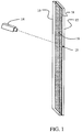
- bonding of the substrates 10, 12 is accomplished using a laser 14 which has a wavelength such that at least one of the substrates (substrate 10 for the example shown) is transparent to that wavelength.
- An interface 15 between the layers provides a change in the index of transmission or optical transmissivity which results in absorption of laser energy at the interface and localized heating to create a bond.
- a heat absorption layer 16 which is opaque or blocking to the laser wavelength and has an affinity for diffusion into the substrates, is deposited on the mating surface 18 of at least one of the substrates (substrate 12 for the example shown).
- the heat absorption layer in example embodiments for glass-to-glass and other substrate bonding herein may be a metal, semiconductor or ceramic material. However, in alternative embodiments other materials having appropriate wavelength absorption and diffusion affinity characteristics may be employed.
- the thickness of the heat absorption layer may be as thin as 1 nm and as thick as desired to compensate for surface roughness or control timing and temperatures of the process as will be described in greater detail subsequently.
- the desired change in transmissivity at the interface can also be accomplished through the use of substrate materials having one substrate which is opaque (low transmissivity to the laser wavelength) or a liquid film having a mismatched index of transmission from the initial substrate.
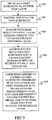
- the bonding process is accomplished as shown in FIG. 2 with reference to the elements disclosed in FIG. 1 for a first example of a glass-to-glass bond wherein a glass substrate 10 of any type generally transparent to the wavelength of the laser 14 being used is selected as the first substrate, 202.
- a change in tansmissivity is created at the interface 15, using, for the example of the first embodiment, a heat absorption layer 16 applied to either the first substrate 10 or the second substrate 12 to be bonded, 204.
- the heat absorption layer may be continuous or segmented strips surrounding features in the substrates such as microfluidic channels.
- the two substrates are then placed in contact with each other with the heat absorption layer being placed such that it is in the interface between the two substrates, 206.
- the surfaces may or may not be extremely well polished.
- the thickness of the heat absorption layer can be thickened to compensate for surface roughness.
- the assembled substrates are then clamped in a fixture, to be described in greater detail subsequently, that is transparent to the wavelength of laser energy being used, 208.
- the laser is then roughly focused on the interface of the assembled substrates in the fixture, 210.
- the laser energy is then applied to the substrates being bonded, 212.
- the heat absorption layer will continue to absorb the energy until a plasma is formed and the temperature of the heat absorption layer is raised to a diffusion temperature, 216.
- the material from the heat absorption layer becomes transparent to the laser energy, 222.
- the heat absorption layer should diffuse at temperature that is higher than the first transition temperature of the glass to ensure that the glass becomes soft and bonds to the neighboring glass. This approach makes the most robust, least particulate sensitive bond joint.
- the entire process takes place such that the bulk material remains at room temperature and only the heat absorption layer and the materials of the substrates immediately adjacent the bond-line itself are elevated to a temperature where the heat absorption layer is diffused into the glass by the laser.
- the width of a single bond-line can vary from approximately 0.001 ⁇ m to 100 ⁇ m or greater and the depth of the bond-line is nominally 500nm into each component of the structure. However, it can vary from a fraction of a micrometer to multiple micro-meters.
- the disclosed process takes advantage of the affinity of metals, ceramics and semiconductors to diffuse into glass at elevated temperatures making the bond-line virtually transparent both in the visible spectrum and to the laser radiation wavelength. Therefore, the process is self-regulating.
- the laser energy passes through the glass with no further heating and the reaction stops. Therefore, the glass is never ablated or over-heated by the laser.
- the material transparency, for the substrate(s) which the laser passes through, should be at least 70 percent at the wavelength at the laser energy wavelength. This allows sufficient power penetration through glass to the depth of the heat absorption layer. If the laser radiation is absorbed, the glass may crack and absorption layer may not be diffused resulting in an incomplete bond or no bond at all. While laser-transparency is desirable for the layer that the laser passes through, it may not be necessary for the second substrate in the stack to be effectively bonded to the first substrate.
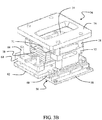
- FIGs. 3A - 3D An example fixture for support of the mated substrates during laser bonding processing is shown in FIGs. 3A - 3D .
- a positioning system 30 incorporates an x-axis motion stage 32 mounted on a base 33 and a y-axis motion stage 34 mounted to the x-axis mounting stage.
- a substrate alignment fixture 36 is mounted on the y-axis motion stage.
- the motion stages may be reversed in vertical stacking and the alignment fixture mounted on the x-axis stage.
- Each motion stage has a drive motor 38 with associated screw drive 40 or similar translation mechanism. Covers 42 shield the operating elements of the motion stages for operator safety.
- a gantry 44 provides support for alignment optics 46 for the laser 14, final focusing optics 48, camera 50 and other instrumentation systems as required for monitoring and control of the bonding operation.
- a power meter 52 is mounted to the x-axis motion stage to be positioned under the laser optical train for measurement and/or calibration of laser power before movement of the alignment fixture under the laser optics for substrate bonding.
- a z-axis motion stage 54 is provided for vertical positioning of the optical and measurement systems with respect to the alignment fixture.
- a computer controller 55 is programmable for translation of the x-axis, y-axis and z-axis motion stages for translation of the laser on the workpiece.
- a single laser may be employed for illuminating multiple substrate work pieces in individual positioning systems by employing beam splitters and focusing optical trains to the multiple positioning systems. It is also possible to replace the fixed lens with an f-theta lens with an X-Y scanner and Z-auto-focus either by itself or in conjunction with a large travel X-Y positioning system.
- a mounting structure 56 is provided to mount the alignment fixture to the y-axis stage.
- the mounting structure is fabricated from attachment plate 58, spacer 60 and engagement support plate 62.
- a vertically translating engagement slider 64 is supported by translation rods 66 received in bushings 67.
- a pneumatic expansion device 68 positioned intermediate the engagement slider 64 and engagement support plate 62 provides vertical adjustment of the engagement slider as will be described subsequently.
- a workpiece holding frame 70 supports a workpiece 71 consisting of the mated substrates 10, 12 as will be described in detail with respect to FIG. 3C .
- Risers 72 extend upward from the engagement support plate 62 to receive an optical flat 74 to be positioned over the holding frame.
- a securing plate 76 mounted with spacers 78 fixes the optical flat to the risers.
- the optical flat is transparent to the laser and may be a fused silica or similar material.
- Deflation of the pneumatic expansion device 68 lowers the engagement slider 64 allowing insertion of the holding frame 70 into position on the engagement slider.
- a receiving frame 79 positions the holding frame. Inflation of the pneumatic expansion device urges the engagement slider and holding frame upward compressing the substrate 10 against the optical flat 74.
- the holding frame 70 includes a base 80, a clamping structure 82 and a substrate carrier 84.
- the clamping structure incorporates a casing 86 which carries a lateral clamp 88 and a longitudinal clamp 90.
- the substrate carrier 84 has a relief 92 sized to closely receive the substrates 10, 12 supporting the lower substrate on a compliant surface 94 integral to or inserted in the relief 92.
- a silicon rubber or similar material may be employed for the compliant surface to provide resilient clamping of the substrates against the optical flat after inflation of the pneumatic expansion device.
- the lateral clamp 88 for the embodiment shown incorporates two vertical arms 96 which extend through slotted apertures 98 in the substrate carrier adjacent the relief 92.
- the lateral clamp is spring loaded to allow outward displacement of the arms 96 by depressing button 100 for insertion of the substrates into the relief.
- the arms engage the sides of the substrates and urge the substrates against the wall of the relief opposite the slotted apertures.
- the longitudinal clamp 90 has a single arm 102 extending through a slotted aperture 104 in the substrate carrier adjacent the relief 92.
- the longitudinal clamp is spring loaded to allow outward displacement of the arm 102 by depressing button 106 for insertion of the substrates into the relief.
- the arm engages the ends of the substrates and urges the substrates against the wall of the relief opposite the slotted aperture. The substrates are securely positioned against two perpendicular surfaces of the relief.
- the alignment fixture 36 mounted on the x-axis motion stage 42 and y-axis motion stage 44 allows translation of the substrate workpiece 71 under the laser beam emitted from the final optics for exposing the heat absorption layer.
- a tracking path may be programmed into the controller 55 for motion stages attached to the holding tool to allow the laser beam impinging on the mated substrates to follow features in the substrates such as microfluidic channels, shown as step 213 in FIG. 2 .
- translation of the substrate holding fixture is employed for the embodiment described, alternative embodiments may employ a stationary hold fixture with translating motion of the laser or laser beam through optical means.
- a laser light trap is required in the bonding fixture such that the laser energy does not burn the fixture or reflect and damage some other aspect of the component.
- the silicon rubber compliant surface 94 absorbs the laser and does not burn.
- a polytetrafluoroethelyne (PTFE) layer such as Teflon® could alternatively be employed or physically defined light traps under the glass chip such as those offered by Thorlabs, 435 Route 206 North Newton, NJ 07860 may be incorporated into the fixture.
- the bonding temperature of the glass When anodic bonding 7ppm/ °C glass to silicon, it is common for the bonding temperature of the glass to be 400°C. Such a temperature will cause a tensile stress of over 200Mpa. This will fracture the glass. However, a room temperature laser bonded substrate stack employing the process described will never be exposed to such a large change in temperature and therefore, will not fracture during the process of bonding. Post bonding, the substrates, which may be in the form of wafers, will be diced into smaller components.
- the stress is reduce by the length reduction of the component as compared to the length of the wafer, i.e., a component that will see a 100°C that is 10 mm long will experience a stress of 5.5 Mpa (0.8 kpi). Glass will very easily survive this stress.
- the laser bond process described herein may be employed for structured Fortruan to silicon or many other ceramics or metals. Since the process of room temperature laser bonding requires a transmissivity change at the interface for creating a heat absorption layer, a transparent plate of glass to a second substrate or blocking plate of material opaque to the laser wave length is employed in much the same manner as for two transparent substrates. However, when bonding a full blocking plate to a transparent plate the process will not be self-regulating and requires that the process must be very carefully controlled such that the blocking plate does not get exposed to so much power that the surface becomes ablated.
- FIG. 4 An example of process control for the laser bonding process when applied to materials as in Example 2 is shown in FIG. 4 wherein the initial step is selecting the material for the blocking heat absorption layer, 402.
- a layer of the blocking heat absorption material is then deposited in a layer of a thickness such that thermal diffusion length (Lfi) is less than the optical penetration depth ( ⁇ -1 ), 404.
- the layer may be deposited on either the first or second substrate on the interfacing surface.
- a laser radiation wave length is then selected for a transmission of greater than 70%, 406.
- a laser radiation pulse width is selected consistent with the thermal diffusion length (Lfi), 408.
- a laser radiation power is selected such that the blocking layer vaporization point is achieved, 410.
- the stage translation rate for the holding tool is controlled to ensure that at the laser radiation pulse rate less than a 50% pulse to pulse overlap is present, 412.
- the holding tool is then translated to achieve the desired laser path on the mated substrates to effect the bond, 414.
- the blocking layer should be a relatively low temperature diffusion material such that it does not melt the polymer being attached to the glass.
- a particularly good material with a low diffusion temperature is AuSn (gold-tin eutectic).
- a gold-tin blocking heat absorption layer has a diffusion temperature of 280°C.
- Another helpful attribute is that the laser-pulse-width approaches the thermal-time-constant of the blocking heat absorption layer layer, i.e., in the femto-second regime. The shorter the pulse length, the less likelihood there is to burn or melt the polymer prior to bonding the high-melting-temperature glass material to the lower temperature melting plastic material. It is also possible to use infared laser radiation without an interlayer and use the blocking nature of the polymer at this wavelength to perform the bonding.
- the laser transmission wavelength was selected such that the laser light was allowed to transmit through the visibly transparent substrate to the visibly blocking substrate.
- silicon has a 55% light transmission between 1um and 10um wave lengths while Bk-7 glass has a near zero transmission above a 3um wave length.
- CO2 laser can penetrate the silicon but not the glass.
- Such a process can be used to perform silicon back side attach to the front side of glass while aligning the laser on the bond location at the interface between the substrates. The laser is going through the silicon, hitting the glass/metal blocking layer and bonding.
- a unique attribute of the room-temperature laser bonding process described herein is the ability to form structure conductive leads into the same interface layer that is being bonded.
- the structure of the leads is formed by the laser track on the mated substrates at the time of bonding. Therefore, it is not necessary to pattern the bonding layer to create a contact lead structure. This also makes for a very green process by avoiding currently required deposition and etching processes.
- the connections may be formed coincident with the bonding process.
- the entire first substrate is metalized, 502, and used as an etch-stop layer.
- the channel would then be patterned and etched, 504.
- the etch mask is then removed while the metal layer remains, 506.
- the metal layer constitutes the blocking heat absorbing layer.
- the fully metalized first substrate is then assembled with a capping second substrate that may or may not be structured with an inlet and outlet via, 508.
- the capping second substrate assembled with the channeled first substrate is then laser bonded together with translation on the predetermined path for laser impingement leaving undiffused metal traces to form leads that pass right through the interface layer, 510.
- the leads do not leak, even though they pass through the bond interface because the bonding process put the interface in compression when it cools. This causes the channel substrate to clamp down on the surface substrate creating a tight seal.
- the lead can be divided into sections such that the compression is applied to a narrow strip but the lead itself remains conductively wide. It is also possible to bond the traces to the adjacent glass without totally diffusing the metal into the glass. The undiffused metal traces may be laser bonded with a shorter pulse length and therefore would bond but not fully diffuse the layer of metal into the glass. Leaving the glass bonded but yet conductive.
- this process can act upon multiple substrate interfaces at the same time. Because the laser process is self-regulating and substrates and the blocking heat absorption layer become transparent to the laser radiation upon diffusion of the heat absorption layer, the laser will pass through the first interface to the next interface and bond it at the same time. While it is not necessary to limit the number of interfaces to a particular number, experiential data indicates that as many layers as seven interfaces can be bonded at one time while leaving contact leads within each interface.
- the substrates when bonding one substrate to another, it is best to begin with at least a 100nm Ra surface finish on interfacing surface of each substrate to be bonded. It is possible for the substrates to be as rough as 1um Ra; however, the hermitic nature of the bond will be questionable unless the blocking/metal layer is substantially thicker.
- the substrate must be cleaned and free of debris as is the case with anodic or fusion bonding. However, since this bonding process does not require being 100% bonded over the entire surface but rather can be seam sealed, the statistics of a good bond are weighted in the direction of a greater yield than that of a typical bonding process.
- the substrates should be clean to a suggested sub-100nm particle/10mm contamination before being assembled with the blocking layer disposed toward the adjacent transparent substrate.
- a compliant layer such as silicone rubber
- a relatively hard (fused silica), transparent surface on the opposing outer substrate employ 138kPa (20psi) as a sufficient amount of pressure to ensure intimate contact between the inside adjacent surfaces.
- a blanket expose light is not used to expose a light sensitive chemical, but rather, a laser is used to diffuse the blocking layer.
- the assembled workpiece can be loaded into a motion platform of the type whereby either the stage positions the substrate under the laser beam or whereby a scanner using an f-theta lens positions the beam over the substrate; either process can be adopted for the purpose of precision or speed, respectively.
- Control software is required to position the stage, scanner or stage/scanner assembly.
- three dimensional computer aided design software creates the bonding path, which is then translated into G-code by computer aided manufacturing software and then again is post processes it into motion board position commands.
Landscapes
- Physics & Mathematics (AREA)
- Engineering & Computer Science (AREA)
- Optics & Photonics (AREA)
- Mechanical Engineering (AREA)
- Chemical & Material Sciences (AREA)
- Plasma & Fusion (AREA)
- Health & Medical Sciences (AREA)
- Toxicology (AREA)
- Electromagnetism (AREA)
- Materials Engineering (AREA)
- Organic Chemistry (AREA)
- Chemical Kinetics & Catalysis (AREA)
- Inorganic Chemistry (AREA)
- Ceramic Engineering (AREA)
- Life Sciences & Earth Sciences (AREA)
- General Chemical & Material Sciences (AREA)
- Geochemistry & Mineralogy (AREA)
- Hematology (AREA)
- Analytical Chemistry (AREA)
- General Health & Medical Sciences (AREA)
- Dispersion Chemistry (AREA)
- Clinical Laboratory Science (AREA)
- Laser Beam Processing (AREA)
- Joining Of Glass To Other Materials (AREA)
- Ceramic Products (AREA)
- Lining Or Joining Of Plastics Or The Like (AREA)
- Micromachines (AREA)
Claims (9)
- Einrichtung zum Laserbinden bei Raumtemperatur, umfassend:einen x-Achsen-Bewegungstisch (32), der an einer Basis (33) angebracht ist;einen y-Achsen-Bewegungstisch (34), der an dem x-Achsen-Bewegungstisch angebracht ist;eine Substratausrichtungsspannvorrichtung (36), die auf dem Bewegungstisch der y-Achse montiert ist, wobei die Ausrichtungsspannvorrichtung angepasst ist, mindestens zwei Substrate mit einer gegenseitigen Schnittstelle als ein Werkstück auszurichten und zu sichern;wobei die Einrichtung dadurch gekennzeichnet ist, dass die Substratausrichtungsspannvorrichtung umfasst:eine Montagestruktur (56) zum Montieren der Ausrichtungsspannvorrichtung an dem y-Achsentisch;einen vertikal translatierenden Eingriffsschieber (64), der von Translationsstangen (66) getragen wird, die sich von der Montagestruktur erstrecken;eine pneumatische Ausdehnungsvorrichtung (68), die zwischen dem Eingriffsschieber und der Montagestruktur für die vertikale Anpassung des Eingriffsschiebers positioniert ist;einen Werkstückhalterahmen (70) zum Tragen des Werkstücks;Steiger (72), die sich von der Montagestruktur nach oben erstrecken, um eine optische Planfläche (74) aufzunehmen, die über dem Halterahmen positioniert werden soll;eine Sicherungsplatte (76), die mit Abstandshaltern montiert ist, um die optische Planfläche an den Steigern zu befestigen; wodurch das Zurückziehen der pneumatischen Ausdehnungsvorrichtung den Eingriffsschieber absenkt, wodurch das Einsetzen des Halterahmens in Position auf dem Eingriffsschieber ermöglicht wird, und das Aufblasen der pneumatischen Ausdehnungsvorrichtung den Eingriffsschieber und den Halterahmen nach oben drückt, wodurch das Werkstück gegen die optische Planfläche gedrückt wird;ein an der Basis montiertes Portal (44) und stützende Ausrichtungsoptik (46) für einen Laser (14), um auf das Werkstück in der Ausrichtungsspannvorrichtung zu fokussieren; undeine Steuerung (55) zum Translatieren des x-Achsen-Bewegungstisches und des y-Achsen-Bewegungstisches für die Bewegung des fokussierten Lasers auf dem Werkstück.
- Einrichtung nach Anspruch 1, wobei der Halterahmen eine Basis (80), eine Klemmstruktur (82) und einen Substratträger (84) umfasst.
- Einrichtung nach Anspruch 2, wobei die Klemmstruktur ein Gehäuse (86) enthält, das eine seitliche Klammer (88) und eine Längsklammer (90) trägt, und der Substratträger einen Absatz (92) aufweist, der bemessen ist, um die Substrate des Werkstücks, das das untere Substrat auf einer nachgiebigen Oberfläche stütz, nah aufzunehmen.
- Einrichtung nach Anspruch 3, wobei die seitliche Klammer erste und zweite vertikale Arme (96) enthält, die sich durch erste und zweite geschlitzte Öffnungen (98) in dem Substratträger neben dem Absatz erstrecken, wobei die seitliche Klammer belastet ist, um eine Verschiebung der Arme nach außen durch das Drücken einer Taste (100) für das Einsetzen der Substrate in den Absatz zu ermöglichen, wobei die Arme in die Seiten der Substrate eingreifen und die Substrate beim Loslassen der Taste gegen die Wand des Absatzes gegenüber der geschlitzten Öffnungen drängen.
- Einrichtung nach Anspruch 3, wobei die Längsklammer einen dritten Arm (102) aufweist, der sich durch eine dritte geschlitzte Öffnung (104) in dem Substratträger neben dem Absatz erstreckt, wobei die Längsklammer belastet ist, um eine Verschiebung des dritten Arms nach außen durch das Drücken einer zweiten Taste (106) für das Einsetzen der Substrate in den Absatz zu ermöglichen, wobei der dritte Arm in die Enden der Substrate eingreift und die Substrate beim Loslassen der zweiten Taste gegen die Wand des Absatzes gegenüber der dritten geschlitzten Öffnungen drängt, wobei dadurch die Substrate gegen zwei senkrechte Oberflächen des Absatzes sicher positioniert werden.
- Einrichtung nach Anspruch 1, wobei jeder Bewegungstisch einen Antriebsmotor (38) mit zugehörigem Schneckenantrieb (40) aufweist.
- Einrichtung nach Anspruch 1, ferner umfassend einen Z-Achsen-Bewegungstisch (54) für die vertikale Positionierung der Ausrichtungsoptik (46) in Bezug auf die Ausrichtungsspannvorrichtung.
- Einrichtung nach Anspruch 1, wobei die optische Planfläche für den Laser transparent ist.
- Einrichtung nach Anspruch 8, wobei die optische Planfläche ein Quarzglas ist.
Priority Applications (1)
| Application Number | Priority Date | Filing Date | Title |
|---|---|---|---|
| EP21152167.9A EP3862130A1 (de) | 2011-11-08 | 2012-11-07 | Verfahren zur glas-glas-, glas-kunststoff- und glas-keramik-/halbleiterverbindung |
Applications Claiming Priority (3)
| Application Number | Priority Date | Filing Date | Title |
|---|---|---|---|
| US13/291,956 US9492990B2 (en) | 2011-11-08 | 2011-11-08 | Room temperature glass-to-glass, glass-to-plastic and glass-to-ceramic/semiconductor bonding |
| PCT/US2012/063977 WO2013070791A1 (en) | 2011-11-08 | 2012-11-07 | Room temperature glass-to-glass, glass-to-plastic and glass-to-ceramic/semiconductor bonding |
| EP12846875.8A EP2776205B1 (de) | 2011-11-08 | 2012-11-07 | Verfahren zur glas-glas-, glas-kunststoff- und glas-keramik/halbleiter-verbindung bei raumtemperatur |
Related Parent Applications (1)
| Application Number | Title | Priority Date | Filing Date |
|---|---|---|---|
| EP12846875.8A Division EP2776205B1 (de) | 2011-11-08 | 2012-11-07 | Verfahren zur glas-glas-, glas-kunststoff- und glas-keramik/halbleiter-verbindung bei raumtemperatur |
Related Child Applications (2)
| Application Number | Title | Priority Date | Filing Date |
|---|---|---|---|
| EP21152167.9A Division EP3862130A1 (de) | 2011-11-08 | 2012-11-07 | Verfahren zur glas-glas-, glas-kunststoff- und glas-keramik-/halbleiterverbindung |
| EP21152167.9A Division-Into EP3862130A1 (de) | 2011-11-08 | 2012-11-07 | Verfahren zur glas-glas-, glas-kunststoff- und glas-keramik-/halbleiterverbindung |
Publications (2)
| Publication Number | Publication Date |
|---|---|
| EP3401052A1 EP3401052A1 (de) | 2018-11-14 |
| EP3401052B1 true EP3401052B1 (de) | 2021-03-10 |
Family
ID=48223003
Family Applications (3)
| Application Number | Title | Priority Date | Filing Date |
|---|---|---|---|
| EP21152167.9A Withdrawn EP3862130A1 (de) | 2011-11-08 | 2012-11-07 | Verfahren zur glas-glas-, glas-kunststoff- und glas-keramik-/halbleiterverbindung |
| EP12846875.8A Active EP2776205B1 (de) | 2011-11-08 | 2012-11-07 | Verfahren zur glas-glas-, glas-kunststoff- und glas-keramik/halbleiter-verbindung bei raumtemperatur |
| EP18178481.0A Active EP3401052B1 (de) | 2011-11-08 | 2012-11-07 | Raumtemperaturlaserschweissgerät |
Family Applications Before (2)
| Application Number | Title | Priority Date | Filing Date |
|---|---|---|---|
| EP21152167.9A Withdrawn EP3862130A1 (de) | 2011-11-08 | 2012-11-07 | Verfahren zur glas-glas-, glas-kunststoff- und glas-keramik-/halbleiterverbindung |
| EP12846875.8A Active EP2776205B1 (de) | 2011-11-08 | 2012-11-07 | Verfahren zur glas-glas-, glas-kunststoff- und glas-keramik/halbleiter-verbindung bei raumtemperatur |
Country Status (13)
| Country | Link |
|---|---|
| US (4) | US9492990B2 (de) |
| EP (3) | EP3862130A1 (de) |
| JP (2) | JP6176538B2 (de) |
| KR (2) | KR102149307B1 (de) |
| CN (2) | CN106186734B (de) |
| AU (3) | AU2012335827A1 (de) |
| BR (1) | BR112014010999A2 (de) |
| CA (1) | CA2854795C (de) |
| IL (2) | IL232470A (de) |
| MX (2) | MX344616B (de) |
| MY (1) | MY167681A (de) |
| SG (2) | SG10201608107QA (de) |
| WO (1) | WO2013070791A1 (de) |
Cited By (1)
| Publication number | Priority date | Publication date | Assignee | Title |
|---|---|---|---|---|
| WO2025209942A1 (fr) * | 2024-04-03 | 2025-10-09 | Universite D'aix Marseille | Procédé de soudure laser |
Families Citing this family (66)
| Publication number | Priority date | Publication date | Assignee | Title |
|---|---|---|---|---|
| EP2608255A1 (de) | 2011-12-23 | 2013-06-26 | Micronit Microfluidics B.V. | Verfahren zum Bonden zweier Substrate und die nach dem Verfahren hergestellte Vorrichtung |
| US20140127857A1 (en) * | 2012-11-07 | 2014-05-08 | Taiwan Semiconductor Manufacturing Company, Ltd. | Carrier Wafers, Methods of Manufacture Thereof, and Packaging Methods |
| US10017849B2 (en) | 2012-11-29 | 2018-07-10 | Corning Incorporated | High rate deposition systems and processes for forming hermetic barrier layers |
| US9666763B2 (en) | 2012-11-30 | 2017-05-30 | Corning Incorporated | Glass sealing with transparent materials having transient absorption properties |
| US9315417B2 (en) | 2013-02-17 | 2016-04-19 | Invenias Inc | Attachment of a cap to a substrate-based device with in situ monitoring of bond quality |
| JP6059059B2 (ja) * | 2013-03-28 | 2017-01-11 | 浜松ホトニクス株式会社 | レーザ加工方法 |
| JP6333961B2 (ja) | 2013-05-10 | 2018-05-30 | コーニング インコーポレイテッド | 低融点ガラス又は吸収薄膜を使用した透明ガラスシートのレーザー溶接 |
| JP2015098042A (ja) * | 2013-11-19 | 2015-05-28 | 日本電気硝子株式会社 | 接合体の製造方法 |
| US10076751B2 (en) | 2013-12-30 | 2018-09-18 | General Electric Company | Systems and methods for reagent storage |
| US10297787B2 (en) | 2014-04-21 | 2019-05-21 | Corning Incorporated | Laser welding of high thermal expansion glasses and glass-ceramics |
| US9230771B2 (en) | 2014-05-05 | 2016-01-05 | Rayotek Scientific, Inc. | Method of manufacturing an electrodeless lamp envelope |
| US9440424B2 (en) * | 2014-05-05 | 2016-09-13 | Picosys Inc | Methods to form and to dismantle hermetically sealed chambers |
| US9795963B2 (en) * | 2014-09-26 | 2017-10-24 | Picosys Incorporated | Method and apparatus for taped interlayer flow cell with masking and conductive traces |
| CN107406292B (zh) | 2014-10-31 | 2021-03-16 | 康宁股份有限公司 | 激光焊接的玻璃封装和制造方法 |
| US10136535B2 (en) * | 2014-12-24 | 2018-11-20 | Medtronic, Inc. | Hermetically-sealed packages including feedthrough assemblies |
| US10124559B2 (en) * | 2014-12-24 | 2018-11-13 | Medtronic, Inc. | Kinetically limited nano-scale diffusion bond structures and methods |
| CN104626543B (zh) * | 2015-01-12 | 2017-02-22 | 中国科学院宁波材料技术与工程研究所 | 热塑性复合材料的焊接方法 |
| JP6584796B2 (ja) * | 2015-03-09 | 2019-10-02 | 日本電気硝子株式会社 | 接合方法と接合装置、及び接合体 |
| DE102015111490A1 (de) * | 2015-07-15 | 2017-01-19 | Schott Ag | Verfahren und Vorrichtung zum lasergestützten Abtrennen eines Teilstücks von einem flächigen Glaselement |
| US20170100597A1 (en) * | 2015-10-12 | 2017-04-13 | Medtronic, Inc. | Sealed implantable medical device and method of forming same |
| CN105413769A (zh) * | 2015-12-22 | 2016-03-23 | 苏州汶颢芯片科技有限公司 | 微流控芯片对准键合装置 |
| EP3187881B1 (de) | 2015-12-28 | 2020-08-26 | Sensirion AG | Thermischer durchflusssensor |
| FR3046738B1 (fr) * | 2016-01-19 | 2018-01-05 | Renault S.A.S | Procede et dispositif d'assemblage par soudage laser par transparence d'une premiere piece comprenant au moins un element de liaison avec une deuxieme piece |
| US10371664B2 (en) | 2016-01-21 | 2019-08-06 | Roche Molecular Systems, Inc. | Use of titanium nitride as a counter electrode |
| WO2017132581A1 (en) * | 2016-01-27 | 2017-08-03 | Picosys, Incorporated | Method and apparatus for room temperature bonding substrates |
| ES2865405T3 (es) * | 2016-05-03 | 2021-10-15 | Prec Valve & Automation Inc | Determinación de una secuencia de unión automática para unión óptica |
| WO2017210701A1 (en) | 2016-06-03 | 2017-12-07 | Raymond Miller Karam | Method and apparatus for vacuum insulated glazings |
| US10562232B2 (en) * | 2016-08-05 | 2020-02-18 | Spm Automation (Canada) Inc. | Controlling direction and magnitude of weld force vector during a plastic welding operation |
| DE102016216844B4 (de) | 2016-09-06 | 2021-06-17 | Evosys Laser GmbH | Verfahren für das Laserstrahl-Kunststoffschweißen sowie Vorrichtung |
| US10821707B2 (en) * | 2018-05-17 | 2020-11-03 | Vaon, Llc | Multi-layer, flat glass structures |
| EP3580596A1 (de) | 2017-02-09 | 2019-12-18 | Corning Incorporated | Flüssiglinsen |
| WO2018153434A1 (de) | 2017-02-21 | 2018-08-30 | Ev Group E. Thallner Gmbh | Verfahren und vorrichtung zum bonden von substraten |
| CN108687442B (zh) * | 2017-03-30 | 2021-10-01 | 法拉第未来公司 | 用于焊接的系统和方法 |
| CN107352504A (zh) * | 2017-06-07 | 2017-11-17 | 扬中市华瑞通讯仪器有限公司 | 一种微流控mems芯片封装方法 |
| CN107382044A (zh) * | 2017-06-15 | 2017-11-24 | 江苏大学 | 一种透明薄玻璃激光透射焊接的方法 |
| CN107695533B (zh) * | 2017-09-26 | 2019-08-20 | 武汉华星光电半导体显示技术有限公司 | 激光切割方法 |
| KR20190041306A (ko) | 2017-10-12 | 2019-04-22 | 주식회사 엘지화학 | 이종 소재 접합체의 제조방법 |
| JP6965722B2 (ja) * | 2017-12-18 | 2021-11-10 | 株式会社デンソー | 溶接装置 |
| TW202417157A (zh) | 2018-02-23 | 2024-05-01 | 美商康寧公司 | 將液體透鏡從一個陣列的液體透鏡中分離的方法 |
| US11012682B2 (en) * | 2018-03-02 | 2021-05-18 | Texas Instruments Incorporated | Linearly actuated display |
| TW201939070A (zh) | 2018-03-09 | 2019-10-01 | 美商康寧公司 | 包括液體透鏡及加熱裝置的相機模組 |
| WO2019209776A1 (en) | 2018-04-27 | 2019-10-31 | Corning Incorporated | Microfluidic devices and methods for manufacturing microfluidic devices |
| WO2019241103A1 (en) | 2018-06-14 | 2019-12-19 | Corning Incorporated | Patterned microfluidic devices and methods for manufacturing the same |
| CN112334230A (zh) | 2018-06-14 | 2021-02-05 | 康宁股份有限公司 | 用于微流体装置的纳米图案化的表面及其制造方法 |
| CN113396353B (zh) | 2018-10-09 | 2023-10-20 | 康宁股份有限公司 | 液体透镜 |
| CN109909610A (zh) * | 2018-12-14 | 2019-06-21 | 华南师范大学 | 一种硅片和玻璃的焊接方法及焊接系统 |
| EP3669979A1 (de) * | 2018-12-20 | 2020-06-24 | IMEC vzw | Mehrstufige mikrofluidische vorrichtung |
| GB2583090A (en) * | 2019-04-12 | 2020-10-21 | Spi Lasers Uk Ltd | Method for joining a first substrate to a second substrate |
| US11422310B2 (en) | 2019-05-24 | 2022-08-23 | Corning Incorporated | Methods of bonding an optical fiber to a substrate using a laser and assemblies fabricated by the same |
| US20210035767A1 (en) * | 2019-07-29 | 2021-02-04 | Applied Materials, Inc. | Methods for repairing a recess of a chamber component |
| US11583955B2 (en) * | 2019-08-06 | 2023-02-21 | Advalue Photonics, Inc. | Laser welding utilizing broadband pulsed laser sources |
| KR102809239B1 (ko) | 2019-08-15 | 2025-05-19 | 코닝 인코포레이티드 | 액체 렌즈의 어레이를 제조하고 어레이를 개별 액체 렌즈로 분리하는 것과 같은, 접합부를 통해 기판들을 접합하고 접합된 기판의 일부를 분리하는 방법 |
| CN110723900A (zh) * | 2019-09-16 | 2020-01-24 | 深圳市裕展精密科技有限公司 | 玻璃复合件、玻璃复合件的制备方法以及激光焊接设备 |
| EP4066031B1 (de) | 2019-11-26 | 2025-02-19 | Corning Research & Development Corporation | Verfahren zum laserschweissen von optischen elementen auf substrate und damit hergestellte optische anordnungen |
| CN111230309B (zh) * | 2020-02-20 | 2022-06-10 | 中国航空制造技术研究院 | 一种新型的涂层清洗方法 |
| DE102020123540A1 (de) | 2020-09-09 | 2022-03-10 | Trumpf Laser- Und Systemtechnik Gmbh | Vorrichtung und Verfahren zum Fügen mindestens zweier Fügepartner |
| CN111933531B (zh) * | 2020-08-11 | 2023-06-20 | 中国电子科技集团公司第三十八研究所 | 一种基于激光键合的立体电路积层制造方法 |
| CN112207474A (zh) * | 2020-10-09 | 2021-01-12 | 王广运 | 一种建筑钢结构墙自动焊接装置 |
| WO2022155087A1 (en) * | 2021-01-12 | 2022-07-21 | Corning Incorporated | Liquid lenses with concentric laser bond paths and methods of making the same |
| CN112939487B (zh) * | 2021-01-28 | 2023-03-10 | 佛山科学技术学院 | 夹心式玻璃微流控芯片双面激光加工装置及方法 |
| DE102021117530A1 (de) | 2021-07-07 | 2023-01-12 | Trumpf Laser- Und Systemtechnik Gmbh | Verfahren zum Fügen mindestens zweier Fügepartner |
| EP4395956A1 (de) | 2021-08-30 | 2024-07-10 | Corning Incorporated | Laserverbindung von glas mit dünner metallfolie |
| CN114045485B (zh) * | 2021-10-26 | 2023-07-18 | 中山大学 | 一种用于原位研究钛合金涂层激光熔覆过程的样品台 |
| US20240140082A1 (en) * | 2022-11-02 | 2024-05-02 | Corning Incorporated | Laser-bonded optical assemblies |
| DE102023110696A1 (de) * | 2023-04-26 | 2024-10-31 | Pac Tech - Packaging Technologies Gmbh | Bondkopf und Bondvorrichtung |
| CN116901454A (zh) * | 2023-08-08 | 2023-10-20 | 上海三束实业有限公司 | 一种塑料与金属的激光焊机设备 |
Family Cites Families (48)
| Publication number | Priority date | Publication date | Assignee | Title |
|---|---|---|---|---|
| CH697814B1 (de) | 2001-01-26 | 2009-02-27 | Tecan Trading Ag | Optisches System und Verfahren zum Anregen und Messen von Fluoreszenz an oder in mit Fluoreszenzfarbstoffen behandelten Proben. |
| JPS59101296A (ja) * | 1982-12-02 | 1984-06-11 | Mitsubishi Heavy Ind Ltd | レ−ザ溶接装置 |
| JPS60214931A (ja) | 1984-04-10 | 1985-10-28 | Toyota Motor Corp | 異種合成樹脂材料の接合方法 |
| JPS60214929A (ja) * | 1984-04-09 | 1985-10-28 | Toyota Motor Corp | 異種合成樹脂材料の接合方法 |
| JPS60246828A (ja) | 1984-05-19 | 1985-12-06 | Howa Mach Ltd | 精紡機等における管替方法及び管替機 |
| JPH06102276B2 (ja) * | 1985-11-11 | 1994-12-14 | 株式会社井上ジャパックス研究所 | レ−ザ溶接方法 |
| DE3783117T2 (de) * | 1986-08-18 | 1993-06-17 | Philips Nv | Verbindung eines elementes aus glass oder keramik und eines elementes aus metall. |
| IT1233073B (it) * | 1989-08-01 | 1992-03-14 | Prima Ind Spa | Macchina laser per l effettuazione di lavorazioni di taglio e saldatu ra |
| US5045668A (en) * | 1990-04-12 | 1991-09-03 | Armco Inc. | Apparatus and method for automatically aligning a welding device for butt welding workpieces |
| JP3135911B2 (ja) * | 1990-10-20 | 2001-02-19 | 大豊工業株式会社 | 金属ガスケットの製造方法 |
| US5304773A (en) * | 1992-02-19 | 1994-04-19 | Trumpf Inc. | Laser work station with optical sensor for calibration of guidance system |
| JPH0985481A (ja) * | 1995-09-19 | 1997-03-31 | Amada Co Ltd | レーザー加工ヘッド |
| JPH10166452A (ja) * | 1996-12-10 | 1998-06-23 | Sekisui Chem Co Ltd | 赤外線によるプラスチックの融着方法および赤外線吸収体 |
| JP2000001598A (ja) | 1998-06-15 | 2000-01-07 | Nok Corp | フェノール樹脂組成物 |
| US20040056006A1 (en) * | 1998-10-01 | 2004-03-25 | The Welding Institute | Welding method |
| GB9821375D0 (en) | 1998-10-01 | 1998-11-25 | Welding Inst | Welding method |
| JP2000343264A (ja) * | 1999-06-04 | 2000-12-12 | Aisan Ind Co Ltd | レーザ溶接装置 |
| JP4366812B2 (ja) * | 2000-02-22 | 2009-11-18 | オムロン株式会社 | 電源回路遮断用リレーユニットおよびそのリレーユニットケース |
| DE50102464D1 (de) * | 2001-03-04 | 2004-07-08 | Inpro Innovations Gmbh | Verfahren zum Verschweissen thermoplastischer Fügeteile mittels Diodenlaserstrahlung |
| DE10149140A1 (de) | 2001-10-05 | 2003-04-17 | Bosch Gmbh Robert | Verfahren zur Verbindung einer Siliziumplatte mit einer weiteren Platte |
| JP3827071B2 (ja) * | 2001-11-02 | 2006-09-27 | 本田技研工業株式会社 | 樹脂部材のレーザ接合方法 |
| JP2003225946A (ja) * | 2002-02-01 | 2003-08-12 | Denso Corp | レーザ接着方法およびレーザ接着装置 |
| US7068891B1 (en) * | 2002-03-12 | 2006-06-27 | Palomar Technologies, Inc. | System and method for positioning optical fibers |
| JP2003340587A (ja) * | 2002-05-24 | 2003-12-02 | Hitachi Via Mechanics Ltd | レーザ加工機 |
| JP2005021916A (ja) * | 2003-06-30 | 2005-01-27 | Olympus Corp | 欠陥修正機能付き顕微鏡装置 |
| JP2005066604A (ja) * | 2003-08-22 | 2005-03-17 | Nissan Motor Co Ltd | レーザ溶接装置 |
| US20070158316A1 (en) | 2006-01-10 | 2007-07-12 | Honeywell International Inc. | System and method for blind laser brazing |
| CN101553340A (zh) * | 2006-09-22 | 2009-10-07 | 国立大学法人大阪大学 | 物质的接合方法、物质接合装置以及接合体及其制造方法 |
| JP4714948B2 (ja) * | 2006-10-05 | 2011-07-06 | 岡山県 | レーザー接合用中間部材及びそれを用いた接合方法 |
| US20080168801A1 (en) | 2007-01-12 | 2008-07-17 | Paul Stephen Danielson | Method of sealing glass |
| DE102007008540A1 (de) * | 2007-02-21 | 2008-08-28 | Friedrich-Schiller-Universität Jena | Verfahren zum Laser-gestützten Bonden, derart gebondete Substrate und deren Verwendung |
| JP2009015131A (ja) * | 2007-07-06 | 2009-01-22 | Sharp Corp | 表示装置の製造方法及び表示装置 |
| JP4806003B2 (ja) * | 2007-12-25 | 2011-11-02 | 財団法人岡山県産業振興財団 | レーザー接合用シート及びそれを用いた接合方法 |
| CN101214580B (zh) * | 2008-01-21 | 2011-04-20 | 山东大学 | 超薄板材脉冲激光微铆接方法及其专用装置 |
| DE102008036467A1 (de) * | 2008-08-05 | 2010-02-11 | Fresenius Medical Care Deutschland Gmbh | Verfahren zur Herstellung eines Verbundteils durch Durchstrahllaserschweißen |
| JP5139922B2 (ja) * | 2008-08-25 | 2013-02-06 | 株式会社ディスコ | レーザー加工装置 |
| JP5183369B2 (ja) * | 2008-08-28 | 2013-04-17 | 株式会社総合車両製作所 | レーザ溶接システムの異常検出方法 |
| WO2010035696A1 (ja) | 2008-09-29 | 2010-04-01 | 芝浦メカトロニクス株式会社 | 接合構造体、接合方法及び接合装置 |
| DE102009029903A1 (de) * | 2009-06-19 | 2010-12-23 | Tesa Se | Verfahren zum Aufbringen einer dauerhaften Prozessmarke auf einem Produkt, insbesondere Glas |
| JP4430131B1 (ja) * | 2009-08-10 | 2010-03-10 | 静岡県 | レーザ溶融接合用ベルト素材及びレーザ接合方法 |
| JP2011048081A (ja) * | 2009-08-26 | 2011-03-10 | Sony Corp | 光学素子、反射低減加工装置及び反射低減加工方法 |
| JP2011056519A (ja) | 2009-09-07 | 2011-03-24 | Osaka Univ | 接合方法および接合体の製造方法 |
| JP2011102230A (ja) * | 2009-10-13 | 2011-05-26 | Canon Inc | 脆性材料の切り欠き加工方法、切り欠きを有する部材の製造方法、及び、表示装置の製造方法 |
| JP5535588B2 (ja) | 2009-11-25 | 2014-07-02 | 浜松ホトニクス株式会社 | ガラス溶着方法及びガラス層定着方法 |
| US20110287607A1 (en) * | 2010-04-02 | 2011-11-24 | Electro Scientific Industries, Inc. | Method and apparatus for improved wafer singulation |
| US8666505B2 (en) | 2010-10-26 | 2014-03-04 | Medtronic, Inc. | Wafer-scale package including power source |
| US8796109B2 (en) | 2010-12-23 | 2014-08-05 | Medtronic, Inc. | Techniques for bonding substrates using an intermediate layer |
| JP6546207B2 (ja) * | 2017-01-19 | 2019-07-17 | ファナック株式会社 | レーザ加工方法 |
-
2011
- 2011-11-08 US US13/291,956 patent/US9492990B2/en active Active
-
2012
- 2012-11-07 CA CA2854795A patent/CA2854795C/en active Active
- 2012-11-07 WO PCT/US2012/063977 patent/WO2013070791A1/en not_active Ceased
- 2012-11-07 AU AU2012335827A patent/AU2012335827A1/en not_active Abandoned
- 2012-11-07 BR BR112014010999A patent/BR112014010999A2/pt active Search and Examination
- 2012-11-07 EP EP21152167.9A patent/EP3862130A1/de not_active Withdrawn
- 2012-11-07 CN CN201610633131.2A patent/CN106186734B/zh active Active
- 2012-11-07 MX MX2014005549A patent/MX344616B/es active IP Right Grant
- 2012-11-07 SG SG10201608107QA patent/SG10201608107QA/en unknown
- 2012-11-07 MY MYPI2014001342A patent/MY167681A/en unknown
- 2012-11-07 MX MX2016017291A patent/MX354017B/es unknown
- 2012-11-07 KR KR1020147014938A patent/KR102149307B1/ko active Active
- 2012-11-07 JP JP2014540226A patent/JP6176538B2/ja not_active Expired - Fee Related
- 2012-11-07 EP EP12846875.8A patent/EP2776205B1/de active Active
- 2012-11-07 SG SG11201402130YA patent/SG11201402130YA/en unknown
- 2012-11-07 KR KR1020197026829A patent/KR102149305B1/ko active Active
- 2012-11-07 EP EP18178481.0A patent/EP3401052B1/de active Active
- 2012-11-07 CN CN201280064365.XA patent/CN104023897B/zh active Active
-
2014
- 2014-05-05 IL IL232470A patent/IL232470A/en active IP Right Grant
-
2016
- 2016-09-23 US US15/275,187 patent/US10293551B2/en active Active
- 2016-11-17 AU AU2016259367A patent/AU2016259367B2/en not_active Ceased
-
2017
- 2017-06-29 JP JP2017126999A patent/JP6676010B2/ja not_active Expired - Fee Related
- 2017-10-19 IL IL255144A patent/IL255144B/en active IP Right Grant
-
2018
- 2018-12-03 AU AU2018274837A patent/AU2018274837B2/en not_active Ceased
-
2019
- 2019-04-08 US US16/378,440 patent/US11571860B2/en active Active
-
2022
- 2022-12-21 US US18/086,220 patent/US20230124770A1/en not_active Abandoned
Non-Patent Citations (1)
| Title |
|---|
| None * |
Cited By (2)
| Publication number | Priority date | Publication date | Assignee | Title |
|---|---|---|---|---|
| WO2025209942A1 (fr) * | 2024-04-03 | 2025-10-09 | Universite D'aix Marseille | Procédé de soudure laser |
| FR3160912A1 (fr) * | 2024-04-03 | 2025-10-10 | Universite D'aix Marseille | Procédé de soudure laser |
Also Published As
Similar Documents
| Publication | Publication Date | Title |
|---|---|---|
| US20230124770A1 (en) | Room temperature glass-to-glass, glass-to-plastic and glass-to-glass ceramic/semiconductor bonding | |
| EP3237141B1 (de) | Kinetisch begrenzte nanoskalige diffusionsverbindungsstrukturen und -verfahren | |
| Tao et al. | Selective bonding and encapsulation for wafer-level vacuum packaging of MEMS and related micro systems | |
| KR20240051231A (ko) | 유리를 얇은 금속 호일에 접합하는 레이저 | |
| US20240063295A1 (en) | Pulsed-laser modification of quantum-particle cells | |
| EP2441518B1 (de) | Verfahren und Vorrichtung zum Thermoformpressbinden | |
| WO2022271443A1 (en) | Assemblies, optical connectors and methods of bonding optical fibers to substrates using a laser beam and electroplating | |
| CN1585103A (zh) | 一种局部键合后封装方法 | |
| JP2008062547A (ja) | レーザ照射による脆性材板割断の方法および装置。 | |
| JP2008290899A (ja) | 絶縁体とシリコンとの積層構造体の製造方法、絶縁体とシリコンとの積層構造体、および検出装置 | |
| CN117916047A (zh) | 玻璃与薄金属箔的激光粘合 | |
| Tao et al. | Laser Bonding and Modeling for Wafer-Level and Chip-Scale Packaging of Micro-Electro-Mechanical Systems | |
| Lorenz | Laser-based packaging of micro-devices | |
| Park | Characterization of transmission laser bonding (TLB) technique for microsystem packaging |
Legal Events
| Date | Code | Title | Description |
|---|---|---|---|
| PUAI | Public reference made under article 153(3) epc to a published international application that has entered the european phase |
Free format text: ORIGINAL CODE: 0009012 |
|
| STAA | Information on the status of an ep patent application or granted ep patent |
Free format text: STATUS: THE APPLICATION HAS BEEN PUBLISHED |
|
| AC | Divisional application: reference to earlier application |
Ref document number: 2776205 Country of ref document: EP Kind code of ref document: P |
|
| AK | Designated contracting states |
Kind code of ref document: A1 Designated state(s): AL AT BE BG CH CY CZ DE DK EE ES FI FR GB GR HR HU IE IS IT LI LT LU LV MC MK MT NL NO PL PT RO RS SE SI SK SM TR |
|
| STAA | Information on the status of an ep patent application or granted ep patent |
Free format text: STATUS: REQUEST FOR EXAMINATION WAS MADE |
|
| 17P | Request for examination filed |
Effective date: 20190513 |
|
| RBV | Designated contracting states (corrected) |
Designated state(s): AL AT BE BG CH CY CZ DE DK EE ES FI FR GB GR HR HU IE IS IT LI LT LU LV MC MK MT NL NO PL PT RO RS SE SI SK SM TR |
|
| GRAP | Despatch of communication of intention to grant a patent |
Free format text: ORIGINAL CODE: EPIDOSNIGR1 |
|
| STAA | Information on the status of an ep patent application or granted ep patent |
Free format text: STATUS: GRANT OF PATENT IS INTENDED |
|
| RIC1 | Information provided on ipc code assigned before grant |
Ipc: C03B 23/20 20060101ALI20200902BHEP Ipc: B23K 101/40 20060101ALI20200902BHEP Ipc: B23K 26/32 20140101ALI20200902BHEP Ipc: B23K 26/03 20060101ALI20200902BHEP Ipc: B23K 26/046 20140101ALI20200902BHEP Ipc: B23K 26/082 20140101ALI20200902BHEP Ipc: B23K 26/211 20140101ALI20200902BHEP Ipc: B23K 26/20 20140101AFI20200902BHEP Ipc: B23K 26/08 20140101ALI20200902BHEP Ipc: B23K 26/244 20140101ALI20200902BHEP Ipc: B23K 101/18 20060101ALI20200902BHEP Ipc: B23K 26/0622 20140101ALI20200902BHEP Ipc: B23K 103/00 20060101ALI20200902BHEP Ipc: B23K 103/18 20060101ALI20200902BHEP |
|
| INTG | Intention to grant announced |
Effective date: 20200921 |
|
| GRAS | Grant fee paid |
Free format text: ORIGINAL CODE: EPIDOSNIGR3 |
|
| GRAA | (expected) grant |
Free format text: ORIGINAL CODE: 0009210 |
|
| STAA | Information on the status of an ep patent application or granted ep patent |
Free format text: STATUS: THE PATENT HAS BEEN GRANTED |
|
| AC | Divisional application: reference to earlier application |
Ref document number: 2776205 Country of ref document: EP Kind code of ref document: P |
|
| AK | Designated contracting states |
Kind code of ref document: B1 Designated state(s): AL AT BE BG CH CY CZ DE DK EE ES FI FR GB GR HR HU IE IS IT LI LT LU LV MC MK MT NL NO PL PT RO RS SE SI SK SM TR |
|
| REG | Reference to a national code |
Ref country code: GB Ref legal event code: FG4D |
|
| REG | Reference to a national code |
Ref country code: AT Ref legal event code: REF Ref document number: 1369284 Country of ref document: AT Kind code of ref document: T Effective date: 20210315 Ref country code: CH Ref legal event code: EP |
|
| REG | Reference to a national code |
Ref country code: DE Ref legal event code: R096 Ref document number: 602012074787 Country of ref document: DE |
|
| REG | Reference to a national code |
Ref country code: IE Ref legal event code: FG4D |
|
| REG | Reference to a national code |
Ref country code: LT Ref legal event code: MG9D |
|
| PG25 | Lapsed in a contracting state [announced via postgrant information from national office to epo] |
Ref country code: LT Free format text: LAPSE BECAUSE OF FAILURE TO SUBMIT A TRANSLATION OF THE DESCRIPTION OR TO PAY THE FEE WITHIN THE PRESCRIBED TIME-LIMIT Effective date: 20210310 Ref country code: NO Free format text: LAPSE BECAUSE OF FAILURE TO SUBMIT A TRANSLATION OF THE DESCRIPTION OR TO PAY THE FEE WITHIN THE PRESCRIBED TIME-LIMIT Effective date: 20210610 Ref country code: BG Free format text: LAPSE BECAUSE OF FAILURE TO SUBMIT A TRANSLATION OF THE DESCRIPTION OR TO PAY THE FEE WITHIN THE PRESCRIBED TIME-LIMIT Effective date: 20210610 Ref country code: GR Free format text: LAPSE BECAUSE OF FAILURE TO SUBMIT A TRANSLATION OF THE DESCRIPTION OR TO PAY THE FEE WITHIN THE PRESCRIBED TIME-LIMIT Effective date: 20210611 Ref country code: FI Free format text: LAPSE BECAUSE OF FAILURE TO SUBMIT A TRANSLATION OF THE DESCRIPTION OR TO PAY THE FEE WITHIN THE PRESCRIBED TIME-LIMIT Effective date: 20210310 Ref country code: HR Free format text: LAPSE BECAUSE OF FAILURE TO SUBMIT A TRANSLATION OF THE DESCRIPTION OR TO PAY THE FEE WITHIN THE PRESCRIBED TIME-LIMIT Effective date: 20210310 |
|
| REG | Reference to a national code |
Ref country code: AT Ref legal event code: MK05 Ref document number: 1369284 Country of ref document: AT Kind code of ref document: T Effective date: 20210310 |
|
| REG | Reference to a national code |
Ref country code: NL Ref legal event code: MP Effective date: 20210310 |
|
| PG25 | Lapsed in a contracting state [announced via postgrant information from national office to epo] |
Ref country code: RS Free format text: LAPSE BECAUSE OF FAILURE TO SUBMIT A TRANSLATION OF THE DESCRIPTION OR TO PAY THE FEE WITHIN THE PRESCRIBED TIME-LIMIT Effective date: 20210310 Ref country code: LV Free format text: LAPSE BECAUSE OF FAILURE TO SUBMIT A TRANSLATION OF THE DESCRIPTION OR TO PAY THE FEE WITHIN THE PRESCRIBED TIME-LIMIT Effective date: 20210310 Ref country code: SE Free format text: LAPSE BECAUSE OF FAILURE TO SUBMIT A TRANSLATION OF THE DESCRIPTION OR TO PAY THE FEE WITHIN THE PRESCRIBED TIME-LIMIT Effective date: 20210310 |
|
| PG25 | Lapsed in a contracting state [announced via postgrant information from national office to epo] |
Ref country code: NL Free format text: LAPSE BECAUSE OF FAILURE TO SUBMIT A TRANSLATION OF THE DESCRIPTION OR TO PAY THE FEE WITHIN THE PRESCRIBED TIME-LIMIT Effective date: 20210310 |
|
| PG25 | Lapsed in a contracting state [announced via postgrant information from national office to epo] |
Ref country code: SM Free format text: LAPSE BECAUSE OF FAILURE TO SUBMIT A TRANSLATION OF THE DESCRIPTION OR TO PAY THE FEE WITHIN THE PRESCRIBED TIME-LIMIT Effective date: 20210310 Ref country code: AT Free format text: LAPSE BECAUSE OF FAILURE TO SUBMIT A TRANSLATION OF THE DESCRIPTION OR TO PAY THE FEE WITHIN THE PRESCRIBED TIME-LIMIT Effective date: 20210310 Ref country code: EE Free format text: LAPSE BECAUSE OF FAILURE TO SUBMIT A TRANSLATION OF THE DESCRIPTION OR TO PAY THE FEE WITHIN THE PRESCRIBED TIME-LIMIT Effective date: 20210310 Ref country code: CZ Free format text: LAPSE BECAUSE OF FAILURE TO SUBMIT A TRANSLATION OF THE DESCRIPTION OR TO PAY THE FEE WITHIN THE PRESCRIBED TIME-LIMIT Effective date: 20210310 |
|
| PG25 | Lapsed in a contracting state [announced via postgrant information from national office to epo] |
Ref country code: IS Free format text: LAPSE BECAUSE OF FAILURE TO SUBMIT A TRANSLATION OF THE DESCRIPTION OR TO PAY THE FEE WITHIN THE PRESCRIBED TIME-LIMIT Effective date: 20210710 Ref country code: PL Free format text: LAPSE BECAUSE OF FAILURE TO SUBMIT A TRANSLATION OF THE DESCRIPTION OR TO PAY THE FEE WITHIN THE PRESCRIBED TIME-LIMIT Effective date: 20210310 Ref country code: PT Free format text: LAPSE BECAUSE OF FAILURE TO SUBMIT A TRANSLATION OF THE DESCRIPTION OR TO PAY THE FEE WITHIN THE PRESCRIBED TIME-LIMIT Effective date: 20210712 Ref country code: RO Free format text: LAPSE BECAUSE OF FAILURE TO SUBMIT A TRANSLATION OF THE DESCRIPTION OR TO PAY THE FEE WITHIN THE PRESCRIBED TIME-LIMIT Effective date: 20210310 Ref country code: SK Free format text: LAPSE BECAUSE OF FAILURE TO SUBMIT A TRANSLATION OF THE DESCRIPTION OR TO PAY THE FEE WITHIN THE PRESCRIBED TIME-LIMIT Effective date: 20210310 |
|
| REG | Reference to a national code |
Ref country code: DE Ref legal event code: R097 Ref document number: 602012074787 Country of ref document: DE |
|
| PLBE | No opposition filed within time limit |
Free format text: ORIGINAL CODE: 0009261 |
|
| STAA | Information on the status of an ep patent application or granted ep patent |
Free format text: STATUS: NO OPPOSITION FILED WITHIN TIME LIMIT |
|
| PG25 | Lapsed in a contracting state [announced via postgrant information from national office to epo] |
Ref country code: ES Free format text: LAPSE BECAUSE OF FAILURE TO SUBMIT A TRANSLATION OF THE DESCRIPTION OR TO PAY THE FEE WITHIN THE PRESCRIBED TIME-LIMIT Effective date: 20210310 Ref country code: AL Free format text: LAPSE BECAUSE OF FAILURE TO SUBMIT A TRANSLATION OF THE DESCRIPTION OR TO PAY THE FEE WITHIN THE PRESCRIBED TIME-LIMIT Effective date: 20210310 Ref country code: DK Free format text: LAPSE BECAUSE OF FAILURE TO SUBMIT A TRANSLATION OF THE DESCRIPTION OR TO PAY THE FEE WITHIN THE PRESCRIBED TIME-LIMIT Effective date: 20210310 |
|
| 26N | No opposition filed |
Effective date: 20211213 |
|
| PG25 | Lapsed in a contracting state [announced via postgrant information from national office to epo] |
Ref country code: SI Free format text: LAPSE BECAUSE OF FAILURE TO SUBMIT A TRANSLATION OF THE DESCRIPTION OR TO PAY THE FEE WITHIN THE PRESCRIBED TIME-LIMIT Effective date: 20210310 |
|
| PG25 | Lapsed in a contracting state [announced via postgrant information from national office to epo] |
Ref country code: IT Free format text: LAPSE BECAUSE OF FAILURE TO SUBMIT A TRANSLATION OF THE DESCRIPTION OR TO PAY THE FEE WITHIN THE PRESCRIBED TIME-LIMIT Effective date: 20210310 |
|
| PG25 | Lapsed in a contracting state [announced via postgrant information from national office to epo] |
Ref country code: IS Free format text: LAPSE BECAUSE OF FAILURE TO SUBMIT A TRANSLATION OF THE DESCRIPTION OR TO PAY THE FEE WITHIN THE PRESCRIBED TIME-LIMIT Effective date: 20210710 |
|
| PG25 | Lapsed in a contracting state [announced via postgrant information from national office to epo] |
Ref country code: MC Free format text: LAPSE BECAUSE OF FAILURE TO SUBMIT A TRANSLATION OF THE DESCRIPTION OR TO PAY THE FEE WITHIN THE PRESCRIBED TIME-LIMIT Effective date: 20210310 |
|
| REG | Reference to a national code |
Ref country code: CH Ref legal event code: PL |
|
| PG25 | Lapsed in a contracting state [announced via postgrant information from national office to epo] |
Ref country code: LU Free format text: LAPSE BECAUSE OF NON-PAYMENT OF DUE FEES Effective date: 20211107 Ref country code: BE Free format text: LAPSE BECAUSE OF NON-PAYMENT OF DUE FEES Effective date: 20211130 |
|
| REG | Reference to a national code |
Ref country code: BE Ref legal event code: MM Effective date: 20211130 |
|
| PG25 | Lapsed in a contracting state [announced via postgrant information from national office to epo] |
Ref country code: LI Free format text: LAPSE BECAUSE OF NON-PAYMENT OF DUE FEES Effective date: 20211130 Ref country code: CH Free format text: LAPSE BECAUSE OF NON-PAYMENT OF DUE FEES Effective date: 20211130 |
|
| PG25 | Lapsed in a contracting state [announced via postgrant information from national office to epo] |
Ref country code: IE Free format text: LAPSE BECAUSE OF NON-PAYMENT OF DUE FEES Effective date: 20211107 |
|
| PG25 | Lapsed in a contracting state [announced via postgrant information from national office to epo] |
Ref country code: CY Free format text: LAPSE BECAUSE OF FAILURE TO SUBMIT A TRANSLATION OF THE DESCRIPTION OR TO PAY THE FEE WITHIN THE PRESCRIBED TIME-LIMIT Effective date: 20210310 |
|
| PG25 | Lapsed in a contracting state [announced via postgrant information from national office to epo] |
Ref country code: HU Free format text: LAPSE BECAUSE OF FAILURE TO SUBMIT A TRANSLATION OF THE DESCRIPTION OR TO PAY THE FEE WITHIN THE PRESCRIBED TIME-LIMIT; INVALID AB INITIO Effective date: 20121107 |
|
| REG | Reference to a national code |
Ref country code: DE Ref legal event code: R081 Ref document number: 602012074787 Country of ref document: DE Owner name: CORNING INCORPORATED, CORNING, US Free format text: FORMER OWNER: PICOSYS INC., SANTA BARBARA, CA, US |
|
| PGFP | Annual fee paid to national office [announced via postgrant information from national office to epo] |
Ref country code: GB Payment date: 20231013 Year of fee payment: 12 |
|
| PGFP | Annual fee paid to national office [announced via postgrant information from national office to epo] |
Ref country code: FR Payment date: 20231010 Year of fee payment: 12 |
|
| PG25 | Lapsed in a contracting state [announced via postgrant information from national office to epo] |
Ref country code: MK Free format text: LAPSE BECAUSE OF FAILURE TO SUBMIT A TRANSLATION OF THE DESCRIPTION OR TO PAY THE FEE WITHIN THE PRESCRIBED TIME-LIMIT Effective date: 20210310 |
|
| PG25 | Lapsed in a contracting state [announced via postgrant information from national office to epo] |
Ref country code: MT Free format text: LAPSE BECAUSE OF FAILURE TO SUBMIT A TRANSLATION OF THE DESCRIPTION OR TO PAY THE FEE WITHIN THE PRESCRIBED TIME-LIMIT Effective date: 20210310 |
|
| PGFP | Annual fee paid to national office [announced via postgrant information from national office to epo] |
Ref country code: DE Payment date: 20241010 Year of fee payment: 13 |
|
| GBPC | Gb: european patent ceased through non-payment of renewal fee |
Effective date: 20241107 |
|
| PG25 | Lapsed in a contracting state [announced via postgrant information from national office to epo] |
Ref country code: GB Free format text: LAPSE BECAUSE OF NON-PAYMENT OF DUE FEES Effective date: 20241107 |
|
| PG25 | Lapsed in a contracting state [announced via postgrant information from national office to epo] |
Ref country code: FR Free format text: LAPSE BECAUSE OF NON-PAYMENT OF DUE FEES Effective date: 20241130 |
|
| PG25 | Lapsed in a contracting state [announced via postgrant information from national office to epo] |
Ref country code: TR Free format text: LAPSE BECAUSE OF FAILURE TO SUBMIT A TRANSLATION OF THE DESCRIPTION OR TO PAY THE FEE WITHIN THE PRESCRIBED TIME-LIMIT Effective date: 20210310 |