EP2441518B1 - Verfahren und Vorrichtung zum Thermoformpressbinden - Google Patents
Verfahren und Vorrichtung zum Thermoformpressbinden Download PDFInfo
- Publication number
- EP2441518B1 EP2441518B1 EP11182722.6A EP11182722A EP2441518B1 EP 2441518 B1 EP2441518 B1 EP 2441518B1 EP 11182722 A EP11182722 A EP 11182722A EP 2441518 B1 EP2441518 B1 EP 2441518B1
- Authority
- EP
- European Patent Office
- Prior art keywords
- section
- chip
- bonding
- thermocompression bonding
- resin
- Prior art date
- Legal status (The legal status is an assumption and is not a legal conclusion. Google has not performed a legal analysis and makes no representation as to the accuracy of the status listed.)
- Active
Links
Images



Classifications
-
- B—PERFORMING OPERATIONS; TRANSPORTING
- B01—PHYSICAL OR CHEMICAL PROCESSES OR APPARATUS IN GENERAL
- B01L—CHEMICAL OR PHYSICAL LABORATORY APPARATUS FOR GENERAL USE
- B01L3/00—Containers or dishes for laboratory use, e.g. laboratory glassware; Droppers
- B01L3/50—Containers for the purpose of retaining a material to be analysed, e.g. test tubes
- B01L3/502—Containers for the purpose of retaining a material to be analysed, e.g. test tubes with fluid transport, e.g. in multi-compartment structures
- B01L3/5027—Containers for the purpose of retaining a material to be analysed, e.g. test tubes with fluid transport, e.g. in multi-compartment structures by integrated microfluidic structures, i.e. dimensions of channels and chambers are such that surface tension forces are important, e.g. lab-on-a-chip
- B01L3/502707—Containers for the purpose of retaining a material to be analysed, e.g. test tubes with fluid transport, e.g. in multi-compartment structures by integrated microfluidic structures, i.e. dimensions of channels and chambers are such that surface tension forces are important, e.g. lab-on-a-chip characterised by the manufacture of the container or its components
-
- B—PERFORMING OPERATIONS; TRANSPORTING
- B29—WORKING OF PLASTICS; WORKING OF SUBSTANCES IN A PLASTIC STATE IN GENERAL
- B29C—SHAPING OR JOINING OF PLASTICS; SHAPING OF MATERIAL IN A PLASTIC STATE, NOT OTHERWISE PROVIDED FOR; AFTER-TREATMENT OF THE SHAPED PRODUCTS, e.g. REPAIRING
- B29C65/00—Joining or sealing of preformed parts, e.g. welding of plastics materials; Apparatus therefor
- B29C65/02—Joining or sealing of preformed parts, e.g. welding of plastics materials; Apparatus therefor by heating, with or without pressure
- B29C65/14—Joining or sealing of preformed parts, e.g. welding of plastics materials; Apparatus therefor by heating, with or without pressure using wave energy, i.e. electromagnetic radiation, or particle radiation
- B29C65/1403—Joining or sealing of preformed parts, e.g. welding of plastics materials; Apparatus therefor by heating, with or without pressure using wave energy, i.e. electromagnetic radiation, or particle radiation characterised by the type of electromagnetic or particle radiation
- B29C65/1412—Infrared [IR] radiation
-
- B—PERFORMING OPERATIONS; TRANSPORTING
- B29—WORKING OF PLASTICS; WORKING OF SUBSTANCES IN A PLASTIC STATE IN GENERAL
- B29C—SHAPING OR JOINING OF PLASTICS; SHAPING OF MATERIAL IN A PLASTIC STATE, NOT OTHERWISE PROVIDED FOR; AFTER-TREATMENT OF THE SHAPED PRODUCTS, e.g. REPAIRING
- B29C65/00—Joining or sealing of preformed parts, e.g. welding of plastics materials; Apparatus therefor
- B29C65/02—Joining or sealing of preformed parts, e.g. welding of plastics materials; Apparatus therefor by heating, with or without pressure
- B29C65/18—Joining or sealing of preformed parts, e.g. welding of plastics materials; Apparatus therefor by heating, with or without pressure using heated tools
-
- B—PERFORMING OPERATIONS; TRANSPORTING
- B29—WORKING OF PLASTICS; WORKING OF SUBSTANCES IN A PLASTIC STATE IN GENERAL
- B29C—SHAPING OR JOINING OF PLASTICS; SHAPING OF MATERIAL IN A PLASTIC STATE, NOT OTHERWISE PROVIDED FOR; AFTER-TREATMENT OF THE SHAPED PRODUCTS, e.g. REPAIRING
- B29C65/00—Joining or sealing of preformed parts, e.g. welding of plastics materials; Apparatus therefor
- B29C65/72—Joining or sealing of preformed parts, e.g. welding of plastics materials; Apparatus therefor by combined operations or combined techniques, e.g. welding and stitching
-
- B—PERFORMING OPERATIONS; TRANSPORTING
- B29—WORKING OF PLASTICS; WORKING OF SUBSTANCES IN A PLASTIC STATE IN GENERAL
- B29C—SHAPING OR JOINING OF PLASTICS; SHAPING OF MATERIAL IN A PLASTIC STATE, NOT OTHERWISE PROVIDED FOR; AFTER-TREATMENT OF THE SHAPED PRODUCTS, e.g. REPAIRING
- B29C66/00—General aspects of processes or apparatus for joining preformed parts
- B29C66/01—General aspects dealing with the joint area or with the area to be joined
- B29C66/02—Preparation of the material, in the area to be joined, prior to joining or welding
- B29C66/024—Thermal pre-treatments
- B29C66/0242—Heating, or preheating, e.g. drying
-
- B—PERFORMING OPERATIONS; TRANSPORTING
- B29—WORKING OF PLASTICS; WORKING OF SUBSTANCES IN A PLASTIC STATE IN GENERAL
- B29C—SHAPING OR JOINING OF PLASTICS; SHAPING OF MATERIAL IN A PLASTIC STATE, NOT OTHERWISE PROVIDED FOR; AFTER-TREATMENT OF THE SHAPED PRODUCTS, e.g. REPAIRING
- B29C66/00—General aspects of processes or apparatus for joining preformed parts
- B29C66/01—General aspects dealing with the joint area or with the area to be joined
- B29C66/02—Preparation of the material, in the area to be joined, prior to joining or welding
- B29C66/026—Chemical pre-treatments
-
- B—PERFORMING OPERATIONS; TRANSPORTING
- B29—WORKING OF PLASTICS; WORKING OF SUBSTANCES IN A PLASTIC STATE IN GENERAL
- B29C—SHAPING OR JOINING OF PLASTICS; SHAPING OF MATERIAL IN A PLASTIC STATE, NOT OTHERWISE PROVIDED FOR; AFTER-TREATMENT OF THE SHAPED PRODUCTS, e.g. REPAIRING
- B29C66/00—General aspects of processes or apparatus for joining preformed parts
- B29C66/01—General aspects dealing with the joint area or with the area to be joined
- B29C66/02—Preparation of the material, in the area to be joined, prior to joining or welding
- B29C66/028—Non-mechanical surface pre-treatments, i.e. by flame treatment, electric discharge treatment, plasma treatment, wave energy or particle radiation
-
- B—PERFORMING OPERATIONS; TRANSPORTING
- B29—WORKING OF PLASTICS; WORKING OF SUBSTANCES IN A PLASTIC STATE IN GENERAL
- B29C—SHAPING OR JOINING OF PLASTICS; SHAPING OF MATERIAL IN A PLASTIC STATE, NOT OTHERWISE PROVIDED FOR; AFTER-TREATMENT OF THE SHAPED PRODUCTS, e.g. REPAIRING
- B29C66/00—General aspects of processes or apparatus for joining preformed parts
- B29C66/01—General aspects dealing with the joint area or with the area to be joined
- B29C66/343—Making tension-free or wrinkle-free joints
-
- B—PERFORMING OPERATIONS; TRANSPORTING
- B29—WORKING OF PLASTICS; WORKING OF SUBSTANCES IN A PLASTIC STATE IN GENERAL
- B29C—SHAPING OR JOINING OF PLASTICS; SHAPING OF MATERIAL IN A PLASTIC STATE, NOT OTHERWISE PROVIDED FOR; AFTER-TREATMENT OF THE SHAPED PRODUCTS, e.g. REPAIRING
- B29C66/00—General aspects of processes or apparatus for joining preformed parts
- B29C66/01—General aspects dealing with the joint area or with the area to be joined
- B29C66/349—Cooling the welding zone on the welding spot
- B29C66/3494—Cooling the welding zone on the welding spot while keeping the welding zone under pressure
-
- B—PERFORMING OPERATIONS; TRANSPORTING
- B29—WORKING OF PLASTICS; WORKING OF SUBSTANCES IN A PLASTIC STATE IN GENERAL
- B29C—SHAPING OR JOINING OF PLASTICS; SHAPING OF MATERIAL IN A PLASTIC STATE, NOT OTHERWISE PROVIDED FOR; AFTER-TREATMENT OF THE SHAPED PRODUCTS, e.g. REPAIRING
- B29C66/00—General aspects of processes or apparatus for joining preformed parts
- B29C66/50—General aspects of joining tubular articles; General aspects of joining long products, i.e. bars or profiled elements; General aspects of joining single elements to tubular articles, hollow articles or bars; General aspects of joining several hollow-preforms to form hollow or tubular articles
- B29C66/51—Joining tubular articles, profiled elements or bars; Joining single elements to tubular articles, hollow articles or bars; Joining several hollow-preforms to form hollow or tubular articles
- B29C66/54—Joining several hollow-preforms, e.g. half-shells, to form hollow articles, e.g. for making balls, containers; Joining several hollow-preforms, e.g. half-cylinders, to form tubular articles
-
- B—PERFORMING OPERATIONS; TRANSPORTING
- B29—WORKING OF PLASTICS; WORKING OF SUBSTANCES IN A PLASTIC STATE IN GENERAL
- B29C—SHAPING OR JOINING OF PLASTICS; SHAPING OF MATERIAL IN A PLASTIC STATE, NOT OTHERWISE PROVIDED FOR; AFTER-TREATMENT OF THE SHAPED PRODUCTS, e.g. REPAIRING
- B29C66/00—General aspects of processes or apparatus for joining preformed parts
- B29C66/90—Measuring or controlling the joining process
- B29C66/91—Measuring or controlling the joining process by measuring or controlling the temperature, the heat or the thermal flux
- B29C66/914—Measuring or controlling the joining process by measuring or controlling the temperature, the heat or the thermal flux by controlling or regulating the temperature, the heat or the thermal flux
- B29C66/9141—Measuring or controlling the joining process by measuring or controlling the temperature, the heat or the thermal flux by controlling or regulating the temperature, the heat or the thermal flux by controlling or regulating the temperature
- B29C66/91411—Measuring or controlling the joining process by measuring or controlling the temperature, the heat or the thermal flux by controlling or regulating the temperature, the heat or the thermal flux by controlling or regulating the temperature of the parts to be joined, e.g. the joining process taking the temperature of the parts to be joined into account
-
- B—PERFORMING OPERATIONS; TRANSPORTING
- B29—WORKING OF PLASTICS; WORKING OF SUBSTANCES IN A PLASTIC STATE IN GENERAL
- B29C—SHAPING OR JOINING OF PLASTICS; SHAPING OF MATERIAL IN A PLASTIC STATE, NOT OTHERWISE PROVIDED FOR; AFTER-TREATMENT OF THE SHAPED PRODUCTS, e.g. REPAIRING
- B29C66/00—General aspects of processes or apparatus for joining preformed parts
- B29C66/90—Measuring or controlling the joining process
- B29C66/91—Measuring or controlling the joining process by measuring or controlling the temperature, the heat or the thermal flux
- B29C66/914—Measuring or controlling the joining process by measuring or controlling the temperature, the heat or the thermal flux by controlling or regulating the temperature, the heat or the thermal flux
- B29C66/9141—Measuring or controlling the joining process by measuring or controlling the temperature, the heat or the thermal flux by controlling or regulating the temperature, the heat or the thermal flux by controlling or regulating the temperature
- B29C66/91441—Measuring or controlling the joining process by measuring or controlling the temperature, the heat or the thermal flux by controlling or regulating the temperature, the heat or the thermal flux by controlling or regulating the temperature the temperature being non-constant over time
- B29C66/91443—Measuring or controlling the joining process by measuring or controlling the temperature, the heat or the thermal flux by controlling or regulating the temperature, the heat or the thermal flux by controlling or regulating the temperature the temperature being non-constant over time following a temperature-time profile
-
- B—PERFORMING OPERATIONS; TRANSPORTING
- B29—WORKING OF PLASTICS; WORKING OF SUBSTANCES IN A PLASTIC STATE IN GENERAL
- B29C—SHAPING OR JOINING OF PLASTICS; SHAPING OF MATERIAL IN A PLASTIC STATE, NOT OTHERWISE PROVIDED FOR; AFTER-TREATMENT OF THE SHAPED PRODUCTS, e.g. REPAIRING
- B29C66/00—General aspects of processes or apparatus for joining preformed parts
- B29C66/90—Measuring or controlling the joining process
- B29C66/91—Measuring or controlling the joining process by measuring or controlling the temperature, the heat or the thermal flux
- B29C66/914—Measuring or controlling the joining process by measuring or controlling the temperature, the heat or the thermal flux by controlling or regulating the temperature, the heat or the thermal flux
- B29C66/9141—Measuring or controlling the joining process by measuring or controlling the temperature, the heat or the thermal flux by controlling or regulating the temperature, the heat or the thermal flux by controlling or regulating the temperature
- B29C66/91441—Measuring or controlling the joining process by measuring or controlling the temperature, the heat or the thermal flux by controlling or regulating the temperature, the heat or the thermal flux by controlling or regulating the temperature the temperature being non-constant over time
- B29C66/91443—Measuring or controlling the joining process by measuring or controlling the temperature, the heat or the thermal flux by controlling or regulating the temperature, the heat or the thermal flux by controlling or regulating the temperature the temperature being non-constant over time following a temperature-time profile
- B29C66/91445—Measuring or controlling the joining process by measuring or controlling the temperature, the heat or the thermal flux by controlling or regulating the temperature, the heat or the thermal flux by controlling or regulating the temperature the temperature being non-constant over time following a temperature-time profile by steps
-
- B—PERFORMING OPERATIONS; TRANSPORTING
- B29—WORKING OF PLASTICS; WORKING OF SUBSTANCES IN A PLASTIC STATE IN GENERAL
- B29C—SHAPING OR JOINING OF PLASTICS; SHAPING OF MATERIAL IN A PLASTIC STATE, NOT OTHERWISE PROVIDED FOR; AFTER-TREATMENT OF THE SHAPED PRODUCTS, e.g. REPAIRING
- B29C66/00—General aspects of processes or apparatus for joining preformed parts
- B29C66/90—Measuring or controlling the joining process
- B29C66/91—Measuring or controlling the joining process by measuring or controlling the temperature, the heat or the thermal flux
- B29C66/919—Measuring or controlling the joining process by measuring or controlling the temperature, the heat or the thermal flux characterised by specific temperature, heat or thermal flux values or ranges
- B29C66/9192—Measuring or controlling the joining process by measuring or controlling the temperature, the heat or the thermal flux characterised by specific temperature, heat or thermal flux values or ranges in explicit relation to another variable, e.g. temperature diagrams
- B29C66/91921—Measuring or controlling the joining process by measuring or controlling the temperature, the heat or the thermal flux characterised by specific temperature, heat or thermal flux values or ranges in explicit relation to another variable, e.g. temperature diagrams in explicit relation to another temperature, e.g. to the softening temperature or softening point, to the thermal degradation temperature or to the ambient temperature
- B29C66/91931—Measuring or controlling the joining process by measuring or controlling the temperature, the heat or the thermal flux characterised by specific temperature, heat or thermal flux values or ranges in explicit relation to another variable, e.g. temperature diagrams in explicit relation to another temperature, e.g. to the softening temperature or softening point, to the thermal degradation temperature or to the ambient temperature in explicit relation to the fusion temperature or melting point of the material of one of the parts to be joined
- B29C66/91935—Measuring or controlling the joining process by measuring or controlling the temperature, the heat or the thermal flux characterised by specific temperature, heat or thermal flux values or ranges in explicit relation to another variable, e.g. temperature diagrams in explicit relation to another temperature, e.g. to the softening temperature or softening point, to the thermal degradation temperature or to the ambient temperature in explicit relation to the fusion temperature or melting point of the material of one of the parts to be joined lower than said fusion temperature
-
- B—PERFORMING OPERATIONS; TRANSPORTING
- B29—WORKING OF PLASTICS; WORKING OF SUBSTANCES IN A PLASTIC STATE IN GENERAL
- B29C—SHAPING OR JOINING OF PLASTICS; SHAPING OF MATERIAL IN A PLASTIC STATE, NOT OTHERWISE PROVIDED FOR; AFTER-TREATMENT OF THE SHAPED PRODUCTS, e.g. REPAIRING
- B29C66/00—General aspects of processes or apparatus for joining preformed parts
- B29C66/90—Measuring or controlling the joining process
- B29C66/91—Measuring or controlling the joining process by measuring or controlling the temperature, the heat or the thermal flux
- B29C66/919—Measuring or controlling the joining process by measuring or controlling the temperature, the heat or the thermal flux characterised by specific temperature, heat or thermal flux values or ranges
- B29C66/9192—Measuring or controlling the joining process by measuring or controlling the temperature, the heat or the thermal flux characterised by specific temperature, heat or thermal flux values or ranges in explicit relation to another variable, e.g. temperature diagrams
- B29C66/91921—Measuring or controlling the joining process by measuring or controlling the temperature, the heat or the thermal flux characterised by specific temperature, heat or thermal flux values or ranges in explicit relation to another variable, e.g. temperature diagrams in explicit relation to another temperature, e.g. to the softening temperature or softening point, to the thermal degradation temperature or to the ambient temperature
- B29C66/91941—Measuring or controlling the joining process by measuring or controlling the temperature, the heat or the thermal flux characterised by specific temperature, heat or thermal flux values or ranges in explicit relation to another variable, e.g. temperature diagrams in explicit relation to another temperature, e.g. to the softening temperature or softening point, to the thermal degradation temperature or to the ambient temperature in explicit relation to Tg, i.e. the glass transition temperature, of the material of one of the parts to be joined
- B29C66/91945—Measuring or controlling the joining process by measuring or controlling the temperature, the heat or the thermal flux characterised by specific temperature, heat or thermal flux values or ranges in explicit relation to another variable, e.g. temperature diagrams in explicit relation to another temperature, e.g. to the softening temperature or softening point, to the thermal degradation temperature or to the ambient temperature in explicit relation to Tg, i.e. the glass transition temperature, of the material of one of the parts to be joined lower than said glass transition temperature
-
- B—PERFORMING OPERATIONS; TRANSPORTING
- B29—WORKING OF PLASTICS; WORKING OF SUBSTANCES IN A PLASTIC STATE IN GENERAL
- B29C—SHAPING OR JOINING OF PLASTICS; SHAPING OF MATERIAL IN A PLASTIC STATE, NOT OTHERWISE PROVIDED FOR; AFTER-TREATMENT OF THE SHAPED PRODUCTS, e.g. REPAIRING
- B29C66/00—General aspects of processes or apparatus for joining preformed parts
- B29C66/90—Measuring or controlling the joining process
- B29C66/91—Measuring or controlling the joining process by measuring or controlling the temperature, the heat or the thermal flux
- B29C66/919—Measuring or controlling the joining process by measuring or controlling the temperature, the heat or the thermal flux characterised by specific temperature, heat or thermal flux values or ranges
- B29C66/9192—Measuring or controlling the joining process by measuring or controlling the temperature, the heat or the thermal flux characterised by specific temperature, heat or thermal flux values or ranges in explicit relation to another variable, e.g. temperature diagrams
- B29C66/91951—Measuring or controlling the joining process by measuring or controlling the temperature, the heat or the thermal flux characterised by specific temperature, heat or thermal flux values or ranges in explicit relation to another variable, e.g. temperature diagrams in explicit relation to time, e.g. temperature-time diagrams
-
- B—PERFORMING OPERATIONS; TRANSPORTING
- B29—WORKING OF PLASTICS; WORKING OF SUBSTANCES IN A PLASTIC STATE IN GENERAL
- B29C—SHAPING OR JOINING OF PLASTICS; SHAPING OF MATERIAL IN A PLASTIC STATE, NOT OTHERWISE PROVIDED FOR; AFTER-TREATMENT OF THE SHAPED PRODUCTS, e.g. REPAIRING
- B29C66/00—General aspects of processes or apparatus for joining preformed parts
- B29C66/90—Measuring or controlling the joining process
- B29C66/92—Measuring or controlling the joining process by measuring or controlling the pressure, the force, the mechanical power or the displacement of the joining tools
- B29C66/924—Measuring or controlling the joining process by measuring or controlling the pressure, the force, the mechanical power or the displacement of the joining tools by controlling or regulating the pressure, the force, the mechanical power or the displacement of the joining tools
- B29C66/9241—Measuring or controlling the joining process by measuring or controlling the pressure, the force, the mechanical power or the displacement of the joining tools by controlling or regulating the pressure, the force, the mechanical power or the displacement of the joining tools by controlling or regulating the pressure, the force or the mechanical power
- B29C66/92441—Measuring or controlling the joining process by measuring or controlling the pressure, the force, the mechanical power or the displacement of the joining tools by controlling or regulating the pressure, the force, the mechanical power or the displacement of the joining tools by controlling or regulating the pressure, the force or the mechanical power the pressure, the force or the mechanical power being non-constant over time
- B29C66/92443—Measuring or controlling the joining process by measuring or controlling the pressure, the force, the mechanical power or the displacement of the joining tools by controlling or regulating the pressure, the force, the mechanical power or the displacement of the joining tools by controlling or regulating the pressure, the force or the mechanical power the pressure, the force or the mechanical power being non-constant over time following a pressure-time profile
-
- B—PERFORMING OPERATIONS; TRANSPORTING
- B29—WORKING OF PLASTICS; WORKING OF SUBSTANCES IN A PLASTIC STATE IN GENERAL
- B29C—SHAPING OR JOINING OF PLASTICS; SHAPING OF MATERIAL IN A PLASTIC STATE, NOT OTHERWISE PROVIDED FOR; AFTER-TREATMENT OF THE SHAPED PRODUCTS, e.g. REPAIRING
- B29C66/00—General aspects of processes or apparatus for joining preformed parts
- B29C66/90—Measuring or controlling the joining process
- B29C66/92—Measuring or controlling the joining process by measuring or controlling the pressure, the force, the mechanical power or the displacement of the joining tools
- B29C66/929—Measuring or controlling the joining process by measuring or controlling the pressure, the force, the mechanical power or the displacement of the joining tools characterized by specific pressure, force, mechanical power or displacement values or ranges
- B29C66/9292—Measuring or controlling the joining process by measuring or controlling the pressure, the force, the mechanical power or the displacement of the joining tools characterized by specific pressure, force, mechanical power or displacement values or ranges in explicit relation to another variable, e.g. pressure diagrams
- B29C66/92921—Measuring or controlling the joining process by measuring or controlling the pressure, the force, the mechanical power or the displacement of the joining tools characterized by specific pressure, force, mechanical power or displacement values or ranges in explicit relation to another variable, e.g. pressure diagrams in specific relation to time, e.g. pressure-time diagrams
-
- B—PERFORMING OPERATIONS; TRANSPORTING
- B81—MICROSTRUCTURAL TECHNOLOGY
- B81C—PROCESSES OR APPARATUS SPECIALLY ADAPTED FOR THE MANUFACTURE OR TREATMENT OF MICROSTRUCTURAL DEVICES OR SYSTEMS
- B81C3/00—Assembling of devices or systems from individually processed components
- B81C3/001—Bonding of two components
-
- B—PERFORMING OPERATIONS; TRANSPORTING
- B01—PHYSICAL OR CHEMICAL PROCESSES OR APPARATUS IN GENERAL
- B01L—CHEMICAL OR PHYSICAL LABORATORY APPARATUS FOR GENERAL USE
- B01L2300/00—Additional constructional details
- B01L2300/16—Surface properties and coatings
- B01L2300/168—Specific optical properties, e.g. reflective coatings
-
- B—PERFORMING OPERATIONS; TRANSPORTING
- B29—WORKING OF PLASTICS; WORKING OF SUBSTANCES IN A PLASTIC STATE IN GENERAL
- B29C—SHAPING OR JOINING OF PLASTICS; SHAPING OF MATERIAL IN A PLASTIC STATE, NOT OTHERWISE PROVIDED FOR; AFTER-TREATMENT OF THE SHAPED PRODUCTS, e.g. REPAIRING
- B29C65/00—Joining or sealing of preformed parts, e.g. welding of plastics materials; Apparatus therefor
- B29C65/002—Joining methods not otherwise provided for
- B29C65/006—Diffusion joining
-
- B—PERFORMING OPERATIONS; TRANSPORTING
- B29—WORKING OF PLASTICS; WORKING OF SUBSTANCES IN A PLASTIC STATE IN GENERAL
- B29C—SHAPING OR JOINING OF PLASTICS; SHAPING OF MATERIAL IN A PLASTIC STATE, NOT OTHERWISE PROVIDED FOR; AFTER-TREATMENT OF THE SHAPED PRODUCTS, e.g. REPAIRING
- B29C65/00—Joining or sealing of preformed parts, e.g. welding of plastics materials; Apparatus therefor
- B29C65/78—Means for handling the parts to be joined, e.g. for making containers or hollow articles, e.g. means for handling sheets, plates, web-like materials, tubular articles, hollow articles or elements to be joined therewith; Means for discharging the joined articles from the joining apparatus
- B29C65/7841—Holding or clamping means for handling purposes
-
- B—PERFORMING OPERATIONS; TRANSPORTING
- B29—WORKING OF PLASTICS; WORKING OF SUBSTANCES IN A PLASTIC STATE IN GENERAL
- B29C—SHAPING OR JOINING OF PLASTICS; SHAPING OF MATERIAL IN A PLASTIC STATE, NOT OTHERWISE PROVIDED FOR; AFTER-TREATMENT OF THE SHAPED PRODUCTS, e.g. REPAIRING
- B29C65/00—Joining or sealing of preformed parts, e.g. welding of plastics materials; Apparatus therefor
- B29C65/82—Testing the joint
- B29C65/8253—Testing the joint by the use of waves or particle radiation, e.g. visual examination, scanning electron microscopy, or X-rays
-
- B—PERFORMING OPERATIONS; TRANSPORTING
- B29—WORKING OF PLASTICS; WORKING OF SUBSTANCES IN A PLASTIC STATE IN GENERAL
- B29C—SHAPING OR JOINING OF PLASTICS; SHAPING OF MATERIAL IN A PLASTIC STATE, NOT OTHERWISE PROVIDED FOR; AFTER-TREATMENT OF THE SHAPED PRODUCTS, e.g. REPAIRING
- B29C66/00—General aspects of processes or apparatus for joining preformed parts
- B29C66/70—General aspects of processes or apparatus for joining preformed parts characterised by the composition, physical properties or the structure of the material of the parts to be joined; Joining with non-plastics material
- B29C66/71—General aspects of processes or apparatus for joining preformed parts characterised by the composition, physical properties or the structure of the material of the parts to be joined; Joining with non-plastics material characterised by the composition of the plastics material of the parts to be joined
-
- B—PERFORMING OPERATIONS; TRANSPORTING
- B29—WORKING OF PLASTICS; WORKING OF SUBSTANCES IN A PLASTIC STATE IN GENERAL
- B29C—SHAPING OR JOINING OF PLASTICS; SHAPING OF MATERIAL IN A PLASTIC STATE, NOT OTHERWISE PROVIDED FOR; AFTER-TREATMENT OF THE SHAPED PRODUCTS, e.g. REPAIRING
- B29C66/00—General aspects of processes or apparatus for joining preformed parts
- B29C66/70—General aspects of processes or apparatus for joining preformed parts characterised by the composition, physical properties or the structure of the material of the parts to be joined; Joining with non-plastics material
- B29C66/73—General aspects of processes or apparatus for joining preformed parts characterised by the composition, physical properties or the structure of the material of the parts to be joined; Joining with non-plastics material characterised by the intensive physical properties of the material of the parts to be joined, by the optical properties of the material of the parts to be joined, by the extensive physical properties of the parts to be joined, by the state of the material of the parts to be joined or by the material of the parts to be joined being a thermoplastic or a thermoset
- B29C66/733—General aspects of processes or apparatus for joining preformed parts characterised by the composition, physical properties or the structure of the material of the parts to be joined; Joining with non-plastics material characterised by the intensive physical properties of the material of the parts to be joined, by the optical properties of the material of the parts to be joined, by the extensive physical properties of the parts to be joined, by the state of the material of the parts to be joined or by the material of the parts to be joined being a thermoplastic or a thermoset characterised by the optical properties of the material of the parts to be joined, e.g. fluorescence, phosphorescence
- B29C66/7336—General aspects of processes or apparatus for joining preformed parts characterised by the composition, physical properties or the structure of the material of the parts to be joined; Joining with non-plastics material characterised by the intensive physical properties of the material of the parts to be joined, by the optical properties of the material of the parts to be joined, by the extensive physical properties of the parts to be joined, by the state of the material of the parts to be joined or by the material of the parts to be joined being a thermoplastic or a thermoset characterised by the optical properties of the material of the parts to be joined, e.g. fluorescence, phosphorescence at least one of the parts to be joined being opaque, transparent or translucent to visible light
- B29C66/73365—General aspects of processes or apparatus for joining preformed parts characterised by the composition, physical properties or the structure of the material of the parts to be joined; Joining with non-plastics material characterised by the intensive physical properties of the material of the parts to be joined, by the optical properties of the material of the parts to be joined, by the extensive physical properties of the parts to be joined, by the state of the material of the parts to be joined or by the material of the parts to be joined being a thermoplastic or a thermoset characterised by the optical properties of the material of the parts to be joined, e.g. fluorescence, phosphorescence at least one of the parts to be joined being opaque, transparent or translucent to visible light at least one of the parts to be joined being transparent or translucent to visible light
-
- B—PERFORMING OPERATIONS; TRANSPORTING
- B29—WORKING OF PLASTICS; WORKING OF SUBSTANCES IN A PLASTIC STATE IN GENERAL
- B29C—SHAPING OR JOINING OF PLASTICS; SHAPING OF MATERIAL IN A PLASTIC STATE, NOT OTHERWISE PROVIDED FOR; AFTER-TREATMENT OF THE SHAPED PRODUCTS, e.g. REPAIRING
- B29C66/00—General aspects of processes or apparatus for joining preformed parts
- B29C66/90—Measuring or controlling the joining process
- B29C66/91—Measuring or controlling the joining process by measuring or controlling the temperature, the heat or the thermal flux
- B29C66/919—Measuring or controlling the joining process by measuring or controlling the temperature, the heat or the thermal flux characterised by specific temperature, heat or thermal flux values or ranges
-
- B—PERFORMING OPERATIONS; TRANSPORTING
- B29—WORKING OF PLASTICS; WORKING OF SUBSTANCES IN A PLASTIC STATE IN GENERAL
- B29K—INDEXING SCHEME ASSOCIATED WITH SUBCLASSES B29B, B29C OR B29D, RELATING TO MOULDING MATERIALS OR TO MATERIALS FOR MOULDS, REINFORCEMENTS, FILLERS OR PREFORMED PARTS, e.g. INSERTS
- B29K2995/00—Properties of moulding materials, reinforcements, fillers, preformed parts or moulds
- B29K2995/0018—Properties of moulding materials, reinforcements, fillers, preformed parts or moulds having particular optical properties, e.g. fluorescent or phosphorescent
- B29K2995/0026—Transparent
- B29K2995/0027—Transparent for light outside the visible spectrum
-
- B—PERFORMING OPERATIONS; TRANSPORTING
- B29—WORKING OF PLASTICS; WORKING OF SUBSTANCES IN A PLASTIC STATE IN GENERAL
- B29L—INDEXING SCHEME ASSOCIATED WITH SUBCLASS B29C, RELATING TO PARTICULAR ARTICLES
- B29L2031/00—Other particular articles
- B29L2031/756—Microarticles, nanoarticles
-
- B—PERFORMING OPERATIONS; TRANSPORTING
- B81—MICROSTRUCTURAL TECHNOLOGY
- B81B—MICROSTRUCTURAL DEVICES OR SYSTEMS, e.g. MICROMECHANICAL DEVICES
- B81B2201/00—Specific applications of microelectromechanical systems
- B81B2201/05—Microfluidics
- B81B2201/058—Microfluidics not provided for in B81B2201/051 - B81B2201/054
-
- B—PERFORMING OPERATIONS; TRANSPORTING
- B81—MICROSTRUCTURAL TECHNOLOGY
- B81C—PROCESSES OR APPARATUS SPECIALLY ADAPTED FOR THE MANUFACTURE OR TREATMENT OF MICROSTRUCTURAL DEVICES OR SYSTEMS
- B81C2203/00—Forming microstructural systems
- B81C2203/03—Bonding two components
- B81C2203/033—Thermal bonding
- B81C2203/037—Thermal bonding techniques not provided for in B81C2203/035 - B81C2203/036
Definitions
- the present disclosure relates to a method and device for thermocompression bonding of resin.
- Thermocompression bonding is known as diffusion bonding with which atoms are diffused on a surface for bonding. With the thermocompression bonding, a plurality of members is heated up to any appropriate temperature of their melting points or lower, and then is put under pressure to a degree not causing plastic deformation as much as possible. As an example, the thermocompression bonding as such is used for bonding of electrode terminals between the substrate of a liquid crystal panel and any external drive circuit (for example, see Japanese Unexamined Patent Application Publication No. 2009-295787 ).
- thermocompression bonding With the general method for thermocompression bonding described in Japanese Unexamined Patent Application Publication No. 2009-295787 , first of all, a section for thermocompression bonding is coated with an anisotropic conductive material, and then is a bare chip being a resin member for thermocompression bonding use temporarily fixed to the thermocompression-bonding section. The thermocompression-bonding section is then disposed on a backup table, and a heated heater bar is brought to come in contact with the bare chip of the thermocompression-bonding section. The thermocompression-bonding section is then put under pressure of a predetermined level with the bare chip remained fixed thereto, and the resulting structure is kept as it is for a predetermined length of time. With heating and pressurization as such, the thermocompression bonding is performed with the thermosetting anisotropic conductive material working as an adhesive.
- the backup table for supporting the bare chip is heated in advance with the aim of preventing the resin member from warping, and of reducing the time to be taken for thermocompression bonding.
- the bare chip placed on the backup table is heated in advance before thermocompression bonding.
- Such preheating makes uniform the temperature distribution of the bare chip during thermocompression bonding, thereby being able to prevent any possible warping of the resin member.
- the backup table and the bare chip are expected to be thermally controlled with good accuracy. Therefore, with the method as such, preventing any possible warping of the bare chip is very difficult.
- the substrate bonding method of this document includes a step of adjusting the temperature of a substrate bonding surface of at least one of a light transmitting first substrate and a second substrate having a light absorbing material dispersed on the bonding surface to be close to the glass transition temperature of a thermoplastic resin constituting the substrate; a step of placing the first substrate and the second substrate one over another and applying a pressure; and a step of applying light from the side of the first substrate.
- deformation of a fluid circuit is suppressed.
- thermocompression bonding of microfluidic chips that comprises a preheating section and a thermocompression-bonding section including a heating section and a pressurization section.
- thermocompression bonding of possibly preventing any warping of a resin member to be caused by thermocompression bonding, and of possibly reducing the time to be taken for processing.
- a method for thermocompression bonding includes preheating a resin member, wherein the resin member is a chip component for use to manufacture a microfluidic chip using an infrared radiation section, and subjecting the resin member to thermocompression bonding using a heating section and a pressurization section, wherein in the heating section a resin material of the resin member having a melting point like a crystalline resin is heated not to reach the melting point, or a resin material of the resin member not having a melting point like a noncrystalline resin is heated not to reach the glass transition point.
- a manufacture device for thermocompression bonding of a microfluidic chip includes, a chip component supply section storing a plurality of chip components each formed with micro fluid paths in advance a preheating section including an infrared radiation section, a thermocompression bonding section including a heating section and a pressurization section, and a transfer section transferring a chip component from the preheating section to the thermocompression bonding section with a heating section and a pressurization section from the preheating section keeping the chip component in a preheated state, characterized in that the heating section is configured to heat a resin material of the chip component having a melting point like a crystalline resin not to reach the melting point, or to heat a resin material of the chip component not having a melting point like a noncrystalline resin not to reach the glass transition point.
- the resin member By a resin member exposed to infrared radiation, the resin member absorbs the infrared thereinto from the radiation surface thereof. As such, a process of preheating is to be completed uniformly in a short time. With the resin member heated uniformly as such, the resin member is not to be warped easily. Also with the process of preheating, the time to be taken for thermocompression bonding is possibly reduced.
- thermocompression bonding of possibly preventing any warping of a resin member to be caused by thermocompression bonding, and of possibly reducing the time to be taken for processing.
- thermocompression bonding in a specific embodiment of the present disclosure.
- FIG. 1 is a flowchart of a manufacture method of a microfluidic chip to which the method for thermocompression bonding in the embodiment is applied.
- a microfluidic chip is a chip component made of resin with a micrometer-sized fluid path formed on a substrate, and is used as a resin member for thermocompression bonding.
- the microfluidic chip made of resin as such is configured by bonding a chip component to another, i.e., one chip component is formed with a groove being a fluid path for use as the substrate, and the other chip component is formed with a groove being a fluid path for use as the lid.
- the method for thermocompression bonding in this embodiment is the method for thermocompression bonding in this embodiment.
- manufacture procedure of a microfluidic chip includes processes of chip component formation (Step S1), surface treatment (Step S2), preheating (Step S3), thermocompression bonding (Step S4), and inspection (fluid path inspection and defect inspection) (Step S5).
- groove-formed chip components for use in a microfluidic chip are formed from a resin member, which is formed by injection molding or film extrusion.
- Step S2 before bonding of the chip component to another, the surfaces thereof for bonding are washed and then subjected to surface modification.
- an infrared lamp heater (IR heater) is used for heating as preprocessing of the thermocompression bonding.
- Step S4 the chip components are heated and then put under pressure with their bonding surfaces in contact with each other so that the chip components are bonded together by thermocompression bonding.
- Step S5 the microfluidic chip formed by thermocompression bonding is inspected for defects in the fluid path, shape, or others thereof.
- the chip components in use are each a resin member formed by injection molding or film extrusion.
- a stamper is made to give a detailed shape such as fluid path to the chip component of the microfluidic chip.
- the stamper for use to manufacture the microfluidic chip as such is made by electrochemical casting (Ni electroforming) using a glass substrate or others as a master, for example.
- the stamper may be made from a glass substrate, a silicon substrate, and others with application of a semiconductor manufacture technology.
- the resin member formed by injection molding or others is formed with a micro fluid path for the microfluidic chip use.
- the resin material for thermocompression bonding use is a thermoplastic resin available for thermocompression bonding, but is not specifically restricted in type as long as the material has a high infrared transmittance.
- the resin material has an infrared transmittance dependent on wavelength.
- the resin material in the wavelength range of 850 nm to 2500 nm both inclusive, preferably has an infrared transmittance of 80% or higher but lower than 100%, and more preferably 85% or higher but lower than 95% excepting at a peak of absorption.
- the infrared transmittance is preferably 40% or higher but lower than 100%, and more preferably 50% or higher but lower than 95%.
- the amount of infrared radiation greatly varies depending on which side of the surface exposed to radiation, i.e., front surface side or undersurface side, and thus the surface is not uniformly exposed to radiation in its entirety.
- the extent of heating varies between the front surface side and the undersurface side, thereby causing warping of the resin member.
- the process of heating is possibly performed swiftly by increasing the amount of infrared radiation to the resin material with an increased output of the IR heater.
- the resin material preferably has a high visible transmittance to a level allowing a visual assessment in a test using the microfluidic chip.
- Such a resin material as above possibly includes acrylic resin such as polymethyl methacrylate (PMMA), polystyrene (PS), polycarbonate (PC), silicon-based resin, cycloolefin polymer (COP), and norbornene-based cyclic polyolefin such as cyclic olefin copolymer (COC), for example.
- acrylic resin such as polymethyl methacrylate (PMMA), polystyrene (PS), polycarbonate (PC), silicon-based resin, cycloolefin polymer (COP), and norbornene-based cyclic polyolefin such as cyclic olefin copolymer (COC), for example.
- the chip components are subjected to surface treatment on their surfaces for thermocompression bonding.
- used is any chemical agent exemplified by an organic solvent.
- plasma discharge is performed.
- the surfaces of the chip components are washed using an organic solvent, and therefore the surfaces of the chip components are softened (swollen). This accordingly increases the degree of adhesion of the resin material during thermocompression bonding.
- the degree of adhesion of the resin material may be increased during thermocompression bonding by surface modification with plasma discharge on their bonding surfaces.
- an organic solvent including low-grade alcohol such as ethanol, or ester such as butyl acetate.
- microfluidic chip may be manufactured by thermocompression bonding between the chip components with no process of surface treatment.
- IR heater infrared lamp heater
- the chip components for thermocompression bonding have a high infrared transmittance as described above.
- the chip components are thus each exposed in its entirety almost uniformly to the infrared radiation coming from the IR heater.
- the chip components are uniformly increased in temperature internally.
- the surface of each of the chip components exposed to radiation from the IR heater is the front surface
- the surface opposite to the surface exposed to radiation from the IR heater is the undersurface
- the average temperature will be almost the same on the surface-side temperature of the resin material, on the undersurface-side temperature thereof, and in the entire chip component.
- any temperature difference in the chip component is possibly controlled during the process of preheating, thereby favorably preventing the chip components from warping.
- the chip components are heated up to the deflection temperature under load of the resin material thereof or lower.
- the chip components are heated up to the temperature in a range of about 1/2 of the deflection temperature under load (° C.), or about 0.4 to 0.6 times higher the temperature.
- the chip components are heated up to about 55 to 80° C.
- thermocompression bonding The higher the heating temperature for the chip components in the process of preheating, the shorter the time taken for thermocompression bonding will be. This is because, by being heated up to a temperature close to the temperature during the process of thermocompression bonding, the chip components reach sooner the temperature for thermocompression bonding during the process thereof.
- the IR heater in use is not specifically restricted in type, the level of output, and others as long as the chip components made of a transparent resin are sufficiently heated thereby.
- thermocompression bonding diffusion bonding
- micro fluid path is formed therein.
- the resulting chip component may suffer a bonding failure, or the micro fluid path therein may be crushed and lost.
- any agent for bonding such as adhesive is not used to prevent any mixture thereof into a test sample.
- their bonding surfaces are brought in direct contact with each other.
- thermocompression bonding the chip components combined as above are kept hold by a thermocompression-bonding section, which is configured by upper and lower compression-bonding heads, for example. These compression-bonding heads apply pressure to the chip components from top and bottom. With the pressure remained applied, the temperature is increased, and then the process of thermocompression bonding (diffusion bonding) is performed. The resulting chip components are then cooled under the pressure, and then the pressure applied to the chip components is reduced by releasing the upper and lower compression-bonding heads.
- thermocompression bonding By the process of thermocompression bonding as such, the chip components are combined together so that a microfluidic chip is formed.
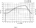
- FIG. 2 shows an exemplary relationship between the degree of pressurization (Press Force) [kN] and the temperature [° C.] during the process of thermocompression bonding, and the time (seconds) after the process of thermocompression bonding is started.
- the temperature indicates the temperature of the upper compression-bonding head (Upper Temp), and the temperature of the lower compression-bonding head (Lower Temp).
- thermocompression-bonding section configured by the thermocompression-bonding heads, for example (0 to 2 seconds).
- the chip components are then put under pressure (at 10 second point).
- the chip components are held under pressure of a predetermined level (at 13 second point).
- the level of pressure is about 13 kN.
- the heating is started to the chip components (at 27 second point).
- the chip components are already heated to the temperature of about 85° C. by the process of preheating.
- the temperature range for thermocompression bonding is from a deflection point under load to a glass transition point.
- the temperature for thermocompression bonding is set to about 125° C. for the heating.
- the chip components are held at the set temperature for 23 seconds.
- the heating time is possibly reduced.
- the time for holding the chip components in the state is possibly reduced.
- the chip components After being held at the predetermined temperature for the predetermined length of time, the chip components are cooled under the pressure of the upper and lower thermocompression-bonding heads (after 105 second point). Then after the temperature is reduced to a sufficiently low value, the application of pressure is stopped (at 123 second point), and then the chip components are released from the thermocompression-bonding section.
- the temperature for the process of thermocompression bonding is increased not to reach the melting point.
- the resin material does not have a melting point like a noncrystalline resin, the temperature is increased not to reach the glass transition point.
- the chip components are heated up to the melting point of the resin material or higher, or up to the glass transition point of the resin material or higher, the micro fluid path formed in the chip component may be deflected or lost.
- the chip components may need to be heated up to the deflection temperature under load or higher.
- the temperature for heating may be in a range from about the heat deflection point to about the glass transition point of the material of the chip components.
- the chip components are preferably heated to be about ⁇ 5° C. of the deflection temperature under load of the resin material, and more preferably, to be about ⁇ 2° C. of the deflection temperature under load thereof.
- the resulting microfluidic chip formed by thermocompression bonding of the chip components is then subjected to inspection.
- the microfluidic chip is checked against a plurality of inspection points.
- the micro fluid path formed inside of the microfluidic chip after the process of thermocompression bonding is measured by size.
- the resulting measurement value is then checked to determine whether it is in a predetermined range or not.
- the microfluidic chip is checked for defects.
- the microfluidic chip When the microfluidic chip is found defective, the chip is separated from other no-defective chips, and then is discarded, for example. When the microfluidic chip passes the inspection, it is subjected to a process of sterilization, packaging, or others if appropriate.
- the process of heating is performed in two steps, i.e., the process of preheating using the IR heater, and the process of thermocompression bonding by heating in the state under pressure.
- the chip components are uniformly heated up to the predetermined temperature so that the time taken for thermocompression bonding is possibly reduced.
- the IR heater in the process of preheating, the resin material is heated uniformly, and therefore any warping of the resin material during heating thereof is prevented.
- FIG. 3 shows an embodiment of a device for thermocompression bonding.
- the device for thermocompression bonding of FIG. 3 is a device for manufacturing a microfluidic chip by the manufacture processes described above.
- the manufacture device of a microfluidic chip is configured to include a chip component supply/discharge section 11, a surface treatment section 12, a compression-bonding section 13, an inspection section 14, and a transfer section for transferring a chip component or a microfluidic chip between the component parts.
- the chip component supply/discharge section 11 is configured by a chip component supply section 11A, and a chip component discharge section 11B.
- the compression-bonding section 13 is configured by a preheating section 13A, and a thermocompression-bonding section 13B.
- the inspection section 14 is configured by a fluid path inspection section 14A, and a defect inspection section 14B.
- the chip component supply section 11A stores a plurality of chip components each formed with a micro fluid path in advance.
- the chip components stored in the chip component supply section 11A as such are sent out for the manufacturing processes of a microfluidic chip.
- the surface treatment section 12 is provided with a surface treatment device for the chip components coming from the chip component supply section 11A.
- the surface treatment device includes an exposure processing device using an organic solvent, e.g., an immersion device or a spray device. Alternatively, a plasma radiation device may be provided.
- the chip components are subjected to surface treatment by plasma discharge on the thermocompression-bonding surfaces thereof, or by exposure thereof to an organic solvent.
- the resulting chip components after the surface treatment are transferred by the transfer section from the surface treatment section 12 to the preheating section 13 of the compression-bonding section 13.
- the preheating section 13A is provided with an infrared radiation section.
- the infrared radiation section includes an infrared lamp heater (IR heater), for example. Using the IR heater, infrared radiation is directed to the surface-treated chip components coming from the surface treatment section 12. By infrared absorption, the chip components are preheated. The preheated chip components are then transferred by a transfer section 13C to the thermocompression-bonding section 13B also in the compression-bonding section 13. At this time, the transfer section 13C transfers the chip components from the preheating section 13A to the thermocompression-bonding section 13B with the preheating temperature remained as it is.
- IR heater infrared lamp heater
- the thermocompression-bonding section 13B forms a microfluidic chip by thermocompression bonding of the chip components coming from the preheating section 13A.
- the thermocompression-bonding section 13B is configured by a pressurization section, and a heating section.
- the pressurization section is exemplified by upper and lower compression-bonding heads for use to combine together the chip components, and then to put these under pressure.
- the heating section is used to heat the pressurization section.
- the two chip components are combined together on their bonding surfaces, and then are put under pressure.
- the chip components are then heated under the pressure for thermocompression bonding (diffusion bonding).
- a microfluidic chip is formed by the chip components.
- the microfluidic chip formed by the compression-bonding section 13 as such is then directed to the fluid path inspection section 14A of the inspection section 14.
- the fluid path inspection section 14A is provided with a general-purpose laser displacement sensor, for example.
- the micro fluid path in the microfluidic chip formed by the process of thermocompression bonding is then measured by size.
- the microfluidic chip is then forwarded to the defect inspection section 14B.
- the defect inspection section 14B includes an image processing device, for example.
- the microfluidic chip is then identified by state using an image, and is then checked for defects.
- the microfluidic chip after the inspection is forwarded from the inspection section 14 to the chip component discharge section 11B of the chip component supply/discharge section 11.
- the chip component discharge section 11B when the microfluidic chip is found defective in the inspection, for example, the chip is separated from others and then is discarded in the chip component discharge section 11B.
- the chip When the microfluidic chip successfully completes the inspection, the chip is directed to the outside of the device from the chip component supply/discharge section 11.
- the finished microfluidic chip is subjected to processes of sterilization, packaging, and others using other devices if appropriate before appearing on the market.
- the surface treatment section 12 when the process of surface treatment is not performed, the surface treatment section 12 is not necessarily provided.
- the component parts i.e., the chip component supply/discharge section 11 and the inspection section 14, may be configured as a device separately from the manufacture device of the microfluidic chip.
- the manufacture device of the microfluidic chip serves well only with the compression-bonding section 13, and may not necessarily include therein the chip component supply/discharge section 11 and the inspection section 14.
- the inspections described above, i.e., the fluid path inspection and the defect inspection are no more than exemplary inspections to be made in the inspection section 14, and if appropriate, any other inspection section may be provided.
- Example and Comparative Example with the manufacture method of the microfluidic chip, a preheated chip component is measured and assessed in terms of the temperature and the degree of warping.
- FIG. 4 shows a method of measuring the degree of warping to be caused to a chip component heated by an infrared lamp heater (IR heater).
- IR heater infrared lamp heater
- a chip component 21 was so disposed that its end portions come in contact with support sections 23, and then was heated by an IR heater 22 from above.
- the chip component 21 in use was a cycloolefin polymer (ZeonexTM 480 manufactured by Zeon Corporation) with the dimensions as 25 ⁇ 75 mm and the thickness of 1 mm.
- the output of the IR heater 22 was set to 1200 w, and the distance from the IR heater 22 to a surface 21A of the chip component 21 was set to be 80 mm.
- the chip component 21 was heated from the room temperature (about 25° C.) to about 70° C.
- the surface 21A side closer to the IR heater 22 was exposed more to the infrared radiation, and was higher in temperature than an undersurface 21B.
- the surface 21A side swelled more than the undersurface 21B, thereby causing such warping of the surface as shown in FIG. 4 . Therefore, in this Example, on the surface 21A side of the chip component 21, a distance 20 from the lowest point of each of the end surfaces to the top portion around the center was regarded as the degree of warping of the chip component 21.
- the temperature on the undersurface 21B side of the chip component 21 was measured together with the degree of warping of the chip component 21.
- FIGS. 5A and 5B each show the light transmittance [%] of the Zeonex 480 used in Example.
- FIGS. 5A and 5B also show the light transmittance [%] of any exemplary resin material available for use as a chip component together with the Zeonex 480, e.g., Zeonex E48R and Zeonex 330R (these are each a cycloolefin polymer manufactured by Zeon Corporation), polycarbonate resin (PC), and polymethyl methacrylate resin (PMMA).
- FIG. 6 shows the typical properties of a general IR heater, i.e., spectral radiant intensity.
- the above-described resin materials all have a high transmittance of about 80 to 90% in the visible wavelength range of 400 to 800 nm.
- the cycloolefin polymer of Zeonex 480, Zeonex E48R, and Zeonex 330R all show a peak of absorption at about 1200 nm and 1400 nm in the infrared wavelength range of 1000 nm or more.
- the cycloolefin polymer described above shows a reduction of transmittance from 90% to about 50%.
- the cycloolefin polymer described above shows a reduction of transmittance from 90% to about 60%.
- the IR heater shows the wavelength distribution in which the intensity shows a gradual decrease with a peak of about 1200 nm.
- the radiation is not uniform because the radiation surface side shows a high degree of absorption, and the infrared radiation is reduced in intensity before reaching the undersurface side.
- the infrared radiation is sufficient in degree also with the wavelength not at the peak of absorption, and the chip component is thus possibly exposed uniformly to the radiation.
- FIG. 7 shows a method of measuring the degree of warping to be caused to a chip component heated using a heated plate.
- the chip component 21 was disposed on a heated plate 24 for a measurement of the degree of warping of the chip component 21.
- the surface temperature of the heated plate 24 was set to 64° C.
- the chip component 21 was the Zeonex 480 manufactured by Zeon Corporation with the dimensions of 25 ⁇ 75 mm and the thickness of 1 mm. Note that, in FIG. 7 , the surface of the chip component 21 in contact with the heated plate 24 was regarded as the surface 21A, and the surface thereof not in contact with the heated plate 24 was regarded as the undersurface 21B.
- the surface 21A in contact with the heated plate 24 was heated first, and thus the surface 21A side swelled more than the undersurface 21B, and thus the surface was warped.
- the degree of warping of the chip component 21 was thus regarded as the distance 20, i.e., from the portion where the surface 21A of the chip component 21 was in contact with the heat plate 24 to the top portion on the end surface.
- FIG. 8 shows the relationship between the measurement results about the chip component 21 in Example as above, i.e., the relationship between the degree of warping of the chip component 21, the temperature of the chip component 21 on the undersurface 21B side, and the preheating time.
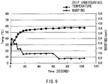
- FIG. 9 shows the relationship in Comparative Example, i.e., the relationship between the degree of warping of the chip component 21, the temperature of the chip component 21 on the undersurface 21B side, and the preheating time.
- FIG. 8 shows that, in Example, the degree of warping is temporarily increased to be about 1 mm immediately after the infrared radiation, but is immediately reduced to be about 0.5 mm and then is stabilized thereat.
- the undersurface of the chip component is at the temperature of about 40° C. when the degree of warping thereof is stably 0.5 mm.
- the heat swiftly reaches the undersurface side of the chip component. What is more, even if the chip component is heated up to a predetermined temperature in a short time, the resulting degree of warping is small. As such, with the process of preheating using the IR heater, the chip component is possibly heated uniformly and in a short time.
- the degree of warping is increased to about 2.5 mm immediately after the heating. Also in Comparative Example, after a lapse of about 20 seconds, the degree of warping is stabilized at about 1.0 mm, but the temperature on the undersurface is about 50° C., i.e., is not yet at a predetermined value for preheating. As such, to achieve the degree of warping stably at 0.5 mm as in Example, the chip component is expected to be heated more for about 70 seconds to increase the undersurface temperature to about 60° C.
- the degree of warping stably at a low value means the heat distribution being uniform in the chip component.
- the surface side in contact with the heated plate is increased in temperature, and only the surface side swells. The degree of warping is thus increased immediately after the heating. Thereafter, with a lapse of time, the heat distribution becomes uniform because the heat on the surface in contact with the heated plate is transferred to the undersurface side so that the degree of warping is reduced with the increasing undersurface temperature. As such, the entire chip component is heated almost uniformly so that the degree of warping becomes stable.
- thermocompression bonding in the embodiment of the present disclosure to a microfluidic chip made of transparent resin.
- present disclosure is applicable to numerous other modifications and variations.
- thermocompression bonding (diffusion bonding) to be performed is to a resin material possibly heated by infrared radiation.
- an infrared lamp heater is used for heating of a resin material.
- the infrared radiation section as such is not specifically restricted in type as long as a resin material is possibly heated by infrared radiation.
- the infrared radiation section may provide ultraviolet radiation and visible radiation together with infrared radiation as long as the infrared radiation is with any necessary level of intensity.
Landscapes
- Engineering & Computer Science (AREA)
- Mechanical Engineering (AREA)
- Physics & Mathematics (AREA)
- Thermal Sciences (AREA)
- Chemical & Material Sciences (AREA)
- Health & Medical Sciences (AREA)
- Electromagnetism (AREA)
- Plasma & Fusion (AREA)
- High Energy & Nuclear Physics (AREA)
- Chemical Kinetics & Catalysis (AREA)
- Toxicology (AREA)
- Microelectronics & Electronic Packaging (AREA)
- General Chemical & Material Sciences (AREA)
- Dispersion Chemistry (AREA)
- Analytical Chemistry (AREA)
- General Health & Medical Sciences (AREA)
- Hematology (AREA)
- Clinical Laboratory Science (AREA)
- Lining Or Joining Of Plastics Or The Like (AREA)
Claims (4)
- Ein Verfahren zum Thermokompressionsbonden, das die folgenden Schritte umfasst:Vorwärmen eines Harzteils (21), wobei das Harzteil eine Chipkomponente zur Verwendung bei der Herstellung eines Mikrofluidik-Chips ist, unter Verwendung eines Infrarotstrahlungsabschnitts (22); undUnterziehen des Harzteils einer Thermokompressionsbindung unter Verwendung eines Heizabschnitts und eines Druckbeaufschlagungsabschnitts, wobei in dem Heizabschnitt,- ein Harzmaterial des Harzteils mit einem Schmelzpunkt wie ein kristallines Harz derart erhitzt wird, dass es den Schmelzpunkt nicht erreicht, oder- ein Harzmaterial des Harzteils, das keinen Schmelzpunkt wie ein nichtkristallines Harz hat, derart erhitzt wird, dass es den Glasübergangspunkt nicht erreicht.
- Das Verfahren zum Thermokompressionsbonden nach Anspruch 1, wobei beim Vorwärmen das Harzteil auf eine Verformungstemperatur unter Last oder niedriger erwärmt wird.
- Das Verfahren zum Thermokompressionsbonden nach Anspruch 1, wobei das Harzteil eine Infrarot-Durchlässigkeit von 80% oder mehr hat, aber weniger als 100% nicht in einem Wellenlängenbereich eines Absorptionsmaximums.
- Eine Herstellungsvorrichtung (13) zum Thermokompressionsbonden von Mikrofluidik-Chips, umfassend:eine Chipkomponenten-Zuführsektion, die eine Vielzahl von Chipkomponenten mit Mikrofluidpfaden speichert;eine Vorwärmsektion (13A) einschließlich einer Infrarotstrahlungssektion (22);einen Thermokompressions-Verbindungsabschnitt (13B) mit einem Heizabschnitt und einem Druckbeaufschlagungsabschnitt; undeinen Transferabschnitt, der ein Chip-Bauteil in den Thermokompressions-Bonding-Abschnitt überführt, mit einem Heizabschnitt und einem Druckbeaufschlagungsabschnitt vom Vorheizabschnitt, der das Chip-Bauteil in einem vorgeheizten Zustand hält, wobei der Heizabschnitt konfiguriert ist- ein Harzmaterial der Chipkomponente mit einem Schmelzpunkt wie ein kristallines Harz derart zu erhitzen, dass der Schmelzpunkt nicht erreicht wird, oder- ein Harzmaterial der Chipkomponente, das keinen Schmelzpunkt wie ein nichtkristallines Harz hat, derart zu erwärmen, um den Glasübergangspunkt nicht zu erreichen.
Applications Claiming Priority (1)
| Application Number | Priority Date | Filing Date | Title |
|---|---|---|---|
| JP2010233935A JP2012086411A (ja) | 2010-10-18 | 2010-10-18 | 熱圧着方法及び熱圧着装置 |
Publications (3)
| Publication Number | Publication Date |
|---|---|
| EP2441518A2 EP2441518A2 (de) | 2012-04-18 |
| EP2441518A3 EP2441518A3 (de) | 2013-12-04 |
| EP2441518B1 true EP2441518B1 (de) | 2020-03-18 |
Family
ID=45524235
Family Applications (1)
| Application Number | Title | Priority Date | Filing Date |
|---|---|---|---|
| EP11182722.6A Active EP2441518B1 (de) | 2010-10-18 | 2011-09-26 | Verfahren und Vorrichtung zum Thermoformpressbinden |
Country Status (3)
| Country | Link |
|---|---|
| US (2) | US8691039B2 (de) |
| EP (1) | EP2441518B1 (de) |
| JP (1) | JP2012086411A (de) |
Families Citing this family (3)
| Publication number | Priority date | Publication date | Assignee | Title |
|---|---|---|---|---|
| JP2012086411A (ja) | 2010-10-18 | 2012-05-10 | Sony Corp | 熱圧着方法及び熱圧着装置 |
| JP2012206026A (ja) * | 2011-03-30 | 2012-10-25 | Sumitomo Bakelite Co Ltd | マイクロ流路デバイスおよびマイクロ流路デバイスの製造方法 |
| CN108162413A (zh) * | 2017-12-27 | 2018-06-15 | 北京百奥芯科技有限公司 | 一种利用溶剂键合制备聚合物微流控芯片的方法 |
Citations (1)
| Publication number | Priority date | Publication date | Assignee | Title |
|---|---|---|---|---|
| JPH09169055A (ja) * | 1995-12-19 | 1997-06-30 | Dainippon Printing Co Ltd | 結晶性熱可塑性樹脂シートの熱ラミネート方法 |
Family Cites Families (21)
| Publication number | Priority date | Publication date | Assignee | Title |
|---|---|---|---|---|
| GB1190567A (en) * | 1966-07-27 | 1970-05-06 | Butyl Products Ltd | A Method of and Apparatus for the Bonding of Butyl Sheet Material. |
| US3904465A (en) * | 1970-02-20 | 1975-09-09 | Mobil Oil Corp | Process and apparatus for the manufacture of embossed film laminations |
| US6911108B2 (en) * | 2001-01-06 | 2005-06-28 | Quantum Group, Inc. | Photon welding devices for joining plastic parts |
| JP3627011B2 (ja) * | 2001-02-13 | 2005-03-09 | インターナショナル・ビジネス・マシーンズ・コーポレーション | 接合方法 |
| JP2002251801A (ja) * | 2001-02-23 | 2002-09-06 | Sony Corp | ディスク状記録媒体の製造方法及び信号転写装置 |
| GB0111438D0 (en) * | 2001-05-10 | 2001-07-04 | Cole Polytechnique Federale De | Polymer bonding by means of plasma activation |
| JP2003011232A (ja) * | 2001-07-03 | 2003-01-15 | Munekata Kk | 熱かしめ方法 |
| US6752894B2 (en) * | 2001-12-14 | 2004-06-22 | 3M Innovative Properties Company | Process for modifying a polymeric surface |
| TWI235111B (en) * | 2002-10-29 | 2005-07-01 | Showa Denko Plastic Prod Co | Bag-making method |
| EP1732744B1 (de) * | 2004-03-30 | 2015-09-02 | Hosokawa Yoko Co., Ltd. | Verfahren und vorrichtung zur herstellung eines beutels mit öffnungsglied |
| JP4643973B2 (ja) * | 2004-11-08 | 2011-03-02 | 富士フイルム株式会社 | ポンプの作動状態の検査方法 |
| JP2006264017A (ja) * | 2005-03-23 | 2006-10-05 | Fuji Photo Film Co Ltd | 積層体のラミネート方法及びラミネート装置 |
| JP2007123343A (ja) * | 2005-10-25 | 2007-05-17 | Toshiba Matsushita Display Technology Co Ltd | 熱圧着方法および熱圧着装置 |
| KR101313359B1 (ko) * | 2006-03-29 | 2013-10-01 | 니폰 제온 가부시키가이샤 | 수지 복합 성형체의 제조방법 |
| JP4919474B2 (ja) * | 2006-07-13 | 2012-04-18 | 国立大学法人京都大学 | 光照射による樹脂の接着方法および樹脂物品の製造方法 |
| JP2008203186A (ja) * | 2007-02-22 | 2008-09-04 | Rohm Co Ltd | 基板の貼り合わせ方法、マイクロチップの製造方法およびマイクロチップ |
| GB0803027D0 (en) * | 2008-02-20 | 2008-03-26 | Epl Composite Solutions Ltd | Bonding apparatus |
| JP2009295787A (ja) | 2008-06-05 | 2009-12-17 | Optrex Corp | 熱圧着方法 |
| WO2010021264A1 (ja) * | 2008-08-21 | 2010-02-25 | コニカミノルタオプト株式会社 | 微細流路チップ製造方法及び微細流路チップ |
| US8058630B2 (en) * | 2009-01-16 | 2011-11-15 | Fluidigm Corporation | Microfluidic devices and methods |
| JP2012086411A (ja) | 2010-10-18 | 2012-05-10 | Sony Corp | 熱圧着方法及び熱圧着装置 |
-
2010
- 2010-10-18 JP JP2010233935A patent/JP2012086411A/ja not_active Ceased
-
2011
- 2011-09-26 EP EP11182722.6A patent/EP2441518B1/de active Active
- 2011-10-11 US US13/270,605 patent/US8691039B2/en active Active
-
2014
- 2014-04-04 US US14/245,566 patent/US9956722B2/en active Active
Patent Citations (1)
| Publication number | Priority date | Publication date | Assignee | Title |
|---|---|---|---|---|
| JPH09169055A (ja) * | 1995-12-19 | 1997-06-30 | Dainippon Printing Co Ltd | 結晶性熱可塑性樹脂シートの熱ラミネート方法 |
Also Published As
| Publication number | Publication date |
|---|---|
| US20140216659A1 (en) | 2014-08-07 |
| US9956722B2 (en) | 2018-05-01 |
| US8691039B2 (en) | 2014-04-08 |
| JP2012086411A (ja) | 2012-05-10 |
| EP2441518A2 (de) | 2012-04-18 |
| US20120205040A1 (en) | 2012-08-16 |
| EP2441518A3 (de) | 2013-12-04 |
Similar Documents
| Publication | Publication Date | Title |
|---|---|---|
| US20230124770A1 (en) | Room temperature glass-to-glass, glass-to-plastic and glass-to-glass ceramic/semiconductor bonding | |
| EP2236575A1 (de) | Verfahren zum harzbinden durch ultraviolette bestrahlung im vakuum, danach verlaufendes verfahren zur herstellung eines harzgegenstands oder mikrochips sowie danach hergestellter harzgegenstand beziehungsweise mikrochip | |
| CN101495582B (zh) | 基于光照射的树脂粘接方法及树脂部件的制造方法 | |
| US8246774B2 (en) | Resin bonding method by photoirradiation, method for producing resin article, resin article produced by the same method, method for producing microchip, and microchip produced by the same method | |
| US9956722B2 (en) | Method and device for thermocompression bonding | |
| JP2013164311A (ja) | 流体取扱装置およびその製造方法 | |
| CN102240850A (zh) | 接合方法、接合装置、以及接合体 | |
| TWI617455B (zh) | 光學組件及其製造方法 | |
| KR20050106485A (ko) | 플라스틱의 접착 방법 | |
| US20140038308A1 (en) | Process for producing composite device, and process for bonding device formed of transparent material to adherend | |
| JP2008203186A (ja) | 基板の貼り合わせ方法、マイクロチップの製造方法およびマイクロチップ | |
| Yu et al. | Rapid bonding enhancement by auxiliary ultrasonic actuation for the fabrication of cyclic olefin copolymer (COC) microfluidic devices | |
| JP2010247056A (ja) | マイクロチップ | |
| TW202134038A (zh) | 樹脂構件之加工方法、樹脂構件之加工裝置及樹脂零件之製造方法 | |
| WO2022172898A1 (ja) | 基材接着方法、基材接着システムおよびマイクロ流体デバイス | |
| TW201718271A (zh) | 2片的基板的貼合方法及2片的基板的貼合裝置 | |
| JP2009229702A (ja) | 光学素子の製造方法 |
Legal Events
| Date | Code | Title | Description |
|---|---|---|---|
| PUAI | Public reference made under article 153(3) epc to a published international application that has entered the european phase |
Free format text: ORIGINAL CODE: 0009012 |
|
| 17P | Request for examination filed |
Effective date: 20111011 |
|
| AK | Designated contracting states |
Kind code of ref document: A2 Designated state(s): AL AT BE BG CH CY CZ DE DK EE ES FI FR GB GR HR HU IE IS IT LI LT LU LV MC MK MT NL NO PL PT RO RS SE SI SK SM TR |
|
| AX | Request for extension of the european patent |
Extension state: BA ME |
|
| PUAL | Search report despatched |
Free format text: ORIGINAL CODE: 0009013 |
|
| AK | Designated contracting states |
Kind code of ref document: A3 Designated state(s): AL AT BE BG CH CY CZ DE DK EE ES FI FR GB GR HR HU IE IS IT LI LT LU LV MC MK MT NL NO PL PT RO RS SE SI SK SM TR |
|
| AX | Request for extension of the european patent |
Extension state: BA ME |
|
| RIC1 | Information provided on ipc code assigned before grant |
Ipc: B29C 35/08 20060101ALN20131025BHEP Ipc: B29C 65/82 20060101ALN20131025BHEP Ipc: B81C 3/00 20060101ALI20131025BHEP Ipc: B01L 3/00 20060101AFI20131025BHEP Ipc: B29C 65/18 20060101ALI20131025BHEP Ipc: B29C 65/78 20060101ALN20131025BHEP |
|
| 17Q | First examination report despatched |
Effective date: 20150219 |
|
| STAA | Information on the status of an ep patent application or granted ep patent |
Free format text: STATUS: EXAMINATION IS IN PROGRESS |
|
| RAP1 | Party data changed (applicant data changed or rights of an application transferred) |
Owner name: SONY CORPORATION |
|
| RAP1 | Party data changed (applicant data changed or rights of an application transferred) |
Owner name: STRATEC CONSUMABLES GMBH |
|
| GRAP | Despatch of communication of intention to grant a patent |
Free format text: ORIGINAL CODE: EPIDOSNIGR1 |
|
| STAA | Information on the status of an ep patent application or granted ep patent |
Free format text: STATUS: GRANT OF PATENT IS INTENDED |
|
| RIC1 | Information provided on ipc code assigned before grant |
Ipc: B01L 3/00 20060101AFI20190924BHEP Ipc: B29C 65/78 20060101ALN20190924BHEP Ipc: B29C 35/08 20060101ALN20190924BHEP Ipc: B81C 3/00 20060101ALI20190924BHEP Ipc: B29C 65/18 20060101ALI20190924BHEP Ipc: B29C 65/82 20060101ALN20190924BHEP |
|
| INTG | Intention to grant announced |
Effective date: 20191010 |
|
| GRAS | Grant fee paid |
Free format text: ORIGINAL CODE: EPIDOSNIGR3 |
|
| GRAA | (expected) grant |
Free format text: ORIGINAL CODE: 0009210 |
|
| STAA | Information on the status of an ep patent application or granted ep patent |
Free format text: STATUS: THE PATENT HAS BEEN GRANTED |
|
| AK | Designated contracting states |
Kind code of ref document: B1 Designated state(s): AL AT BE BG CH CY CZ DE DK EE ES FI FR GB GR HR HU IE IS IT LI LT LU LV MC MK MT NL NO PL PT RO RS SE SI SK SM TR |
|
| REG | Reference to a national code |
Ref country code: GB Ref legal event code: FG4D |
|
| REG | Reference to a national code |
Ref country code: DE Ref legal event code: R096 Ref document number: 602011065638 Country of ref document: DE |
|
| REG | Reference to a national code |
Ref country code: AT Ref legal event code: REF Ref document number: 1245281 Country of ref document: AT Kind code of ref document: T Effective date: 20200415 Ref country code: IE Ref legal event code: FG4D |
|
| REG | Reference to a national code |
Ref country code: CH Ref legal event code: NV Representative=s name: 24IP LAW GROUP, CH |
|
| PG25 | Lapsed in a contracting state [announced via postgrant information from national office to epo] |
Ref country code: RS Free format text: LAPSE BECAUSE OF FAILURE TO SUBMIT A TRANSLATION OF THE DESCRIPTION OR TO PAY THE FEE WITHIN THE PRESCRIBED TIME-LIMIT Effective date: 20200318 Ref country code: FI Free format text: LAPSE BECAUSE OF FAILURE TO SUBMIT A TRANSLATION OF THE DESCRIPTION OR TO PAY THE FEE WITHIN THE PRESCRIBED TIME-LIMIT Effective date: 20200318 Ref country code: NO Free format text: LAPSE BECAUSE OF FAILURE TO SUBMIT A TRANSLATION OF THE DESCRIPTION OR TO PAY THE FEE WITHIN THE PRESCRIBED TIME-LIMIT Effective date: 20200618 |
|
| REG | Reference to a national code |
Ref country code: NL Ref legal event code: MP Effective date: 20200318 |
|
| PG25 | Lapsed in a contracting state [announced via postgrant information from national office to epo] |
Ref country code: LV Free format text: LAPSE BECAUSE OF FAILURE TO SUBMIT A TRANSLATION OF THE DESCRIPTION OR TO PAY THE FEE WITHIN THE PRESCRIBED TIME-LIMIT Effective date: 20200318 Ref country code: SE Free format text: LAPSE BECAUSE OF FAILURE TO SUBMIT A TRANSLATION OF THE DESCRIPTION OR TO PAY THE FEE WITHIN THE PRESCRIBED TIME-LIMIT Effective date: 20200318 Ref country code: BG Free format text: LAPSE BECAUSE OF FAILURE TO SUBMIT A TRANSLATION OF THE DESCRIPTION OR TO PAY THE FEE WITHIN THE PRESCRIBED TIME-LIMIT Effective date: 20200618 Ref country code: GR Free format text: LAPSE BECAUSE OF FAILURE TO SUBMIT A TRANSLATION OF THE DESCRIPTION OR TO PAY THE FEE WITHIN THE PRESCRIBED TIME-LIMIT Effective date: 20200619 Ref country code: HR Free format text: LAPSE BECAUSE OF FAILURE TO SUBMIT A TRANSLATION OF THE DESCRIPTION OR TO PAY THE FEE WITHIN THE PRESCRIBED TIME-LIMIT Effective date: 20200318 |
|
| REG | Reference to a national code |
Ref country code: LT Ref legal event code: MG4D |
|
| PG25 | Lapsed in a contracting state [announced via postgrant information from national office to epo] |
Ref country code: NL Free format text: LAPSE BECAUSE OF FAILURE TO SUBMIT A TRANSLATION OF THE DESCRIPTION OR TO PAY THE FEE WITHIN THE PRESCRIBED TIME-LIMIT Effective date: 20200318 |
|
| REG | Reference to a national code |
Ref country code: AT Ref legal event code: UEP Ref document number: 1245281 Country of ref document: AT Kind code of ref document: T Effective date: 20200318 |
|
| PG25 | Lapsed in a contracting state [announced via postgrant information from national office to epo] |
Ref country code: SK Free format text: LAPSE BECAUSE OF FAILURE TO SUBMIT A TRANSLATION OF THE DESCRIPTION OR TO PAY THE FEE WITHIN THE PRESCRIBED TIME-LIMIT Effective date: 20200318 Ref country code: EE Free format text: LAPSE BECAUSE OF FAILURE TO SUBMIT A TRANSLATION OF THE DESCRIPTION OR TO PAY THE FEE WITHIN THE PRESCRIBED TIME-LIMIT Effective date: 20200318 Ref country code: SM Free format text: LAPSE BECAUSE OF FAILURE TO SUBMIT A TRANSLATION OF THE DESCRIPTION OR TO PAY THE FEE WITHIN THE PRESCRIBED TIME-LIMIT Effective date: 20200318 Ref country code: IS Free format text: LAPSE BECAUSE OF FAILURE TO SUBMIT A TRANSLATION OF THE DESCRIPTION OR TO PAY THE FEE WITHIN THE PRESCRIBED TIME-LIMIT Effective date: 20200718 Ref country code: CZ Free format text: LAPSE BECAUSE OF FAILURE TO SUBMIT A TRANSLATION OF THE DESCRIPTION OR TO PAY THE FEE WITHIN THE PRESCRIBED TIME-LIMIT Effective date: 20200318 Ref country code: PT Free format text: LAPSE BECAUSE OF FAILURE TO SUBMIT A TRANSLATION OF THE DESCRIPTION OR TO PAY THE FEE WITHIN THE PRESCRIBED TIME-LIMIT Effective date: 20200812 Ref country code: RO Free format text: LAPSE BECAUSE OF FAILURE TO SUBMIT A TRANSLATION OF THE DESCRIPTION OR TO PAY THE FEE WITHIN THE PRESCRIBED TIME-LIMIT Effective date: 20200318 Ref country code: LT Free format text: LAPSE BECAUSE OF FAILURE TO SUBMIT A TRANSLATION OF THE DESCRIPTION OR TO PAY THE FEE WITHIN THE PRESCRIBED TIME-LIMIT Effective date: 20200318 |
|
| REG | Reference to a national code |
Ref country code: DE Ref legal event code: R097 Ref document number: 602011065638 Country of ref document: DE |
|
| PLBE | No opposition filed within time limit |
Free format text: ORIGINAL CODE: 0009261 |
|
| STAA | Information on the status of an ep patent application or granted ep patent |
Free format text: STATUS: NO OPPOSITION FILED WITHIN TIME LIMIT |
|
| PG25 | Lapsed in a contracting state [announced via postgrant information from national office to epo] |
Ref country code: ES Free format text: LAPSE BECAUSE OF FAILURE TO SUBMIT A TRANSLATION OF THE DESCRIPTION OR TO PAY THE FEE WITHIN THE PRESCRIBED TIME-LIMIT Effective date: 20200318 Ref country code: DK Free format text: LAPSE BECAUSE OF FAILURE TO SUBMIT A TRANSLATION OF THE DESCRIPTION OR TO PAY THE FEE WITHIN THE PRESCRIBED TIME-LIMIT Effective date: 20200318 |
|
| REG | Reference to a national code |
Ref country code: DE Ref legal event code: R082 Ref document number: 602011065638 Country of ref document: DE Representative=s name: FORTMANN TEGETHOFF PATENT- UND RECHTSANWAELTE , DE Ref country code: DE Ref legal event code: R082 Ref document number: 602011065638 Country of ref document: DE Representative=s name: FORTMANN TEGETHOFF PATENT- UND RECHTSANWAELTE, DE |
|
| 26N | No opposition filed |
Effective date: 20201221 |
|
| PG25 | Lapsed in a contracting state [announced via postgrant information from national office to epo] |
Ref country code: PL Free format text: LAPSE BECAUSE OF FAILURE TO SUBMIT A TRANSLATION OF THE DESCRIPTION OR TO PAY THE FEE WITHIN THE PRESCRIBED TIME-LIMIT Effective date: 20200318 |
|
| PG25 | Lapsed in a contracting state [announced via postgrant information from national office to epo] |
Ref country code: MC Free format text: LAPSE BECAUSE OF FAILURE TO SUBMIT A TRANSLATION OF THE DESCRIPTION OR TO PAY THE FEE WITHIN THE PRESCRIBED TIME-LIMIT Effective date: 20200318 |
|
| PG25 | Lapsed in a contracting state [announced via postgrant information from national office to epo] |
Ref country code: SI Free format text: LAPSE BECAUSE OF FAILURE TO SUBMIT A TRANSLATION OF THE DESCRIPTION OR TO PAY THE FEE WITHIN THE PRESCRIBED TIME-LIMIT Effective date: 20200318 |
|
| REG | Reference to a national code |
Ref country code: BE Ref legal event code: MM Effective date: 20200930 |
|
| PG25 | Lapsed in a contracting state [announced via postgrant information from national office to epo] |
Ref country code: LU Free format text: LAPSE BECAUSE OF NON-PAYMENT OF DUE FEES Effective date: 20200926 |
|
| PG25 | Lapsed in a contracting state [announced via postgrant information from national office to epo] |
Ref country code: BE Free format text: LAPSE BECAUSE OF NON-PAYMENT OF DUE FEES Effective date: 20200930 Ref country code: IE Free format text: LAPSE BECAUSE OF NON-PAYMENT OF DUE FEES Effective date: 20200926 |
|
| PG25 | Lapsed in a contracting state [announced via postgrant information from national office to epo] |
Ref country code: TR Free format text: LAPSE BECAUSE OF FAILURE TO SUBMIT A TRANSLATION OF THE DESCRIPTION OR TO PAY THE FEE WITHIN THE PRESCRIBED TIME-LIMIT Effective date: 20200318 Ref country code: MT Free format text: LAPSE BECAUSE OF FAILURE TO SUBMIT A TRANSLATION OF THE DESCRIPTION OR TO PAY THE FEE WITHIN THE PRESCRIBED TIME-LIMIT Effective date: 20200318 Ref country code: CY Free format text: LAPSE BECAUSE OF FAILURE TO SUBMIT A TRANSLATION OF THE DESCRIPTION OR TO PAY THE FEE WITHIN THE PRESCRIBED TIME-LIMIT Effective date: 20200318 |
|
| PG25 | Lapsed in a contracting state [announced via postgrant information from national office to epo] |
Ref country code: MK Free format text: LAPSE BECAUSE OF FAILURE TO SUBMIT A TRANSLATION OF THE DESCRIPTION OR TO PAY THE FEE WITHIN THE PRESCRIBED TIME-LIMIT Effective date: 20200318 Ref country code: AL Free format text: LAPSE BECAUSE OF FAILURE TO SUBMIT A TRANSLATION OF THE DESCRIPTION OR TO PAY THE FEE WITHIN THE PRESCRIBED TIME-LIMIT Effective date: 20200318 |
|
| P01 | Opt-out of the competence of the unified patent court (upc) registered |
Effective date: 20230711 |
|
| REG | Reference to a national code |
Ref country code: CH Ref legal event code: U11 Free format text: ST27 STATUS EVENT CODE: U-0-0-U10-U11 (AS PROVIDED BY THE NATIONAL OFFICE) Effective date: 20251001 |
|
| PGFP | Annual fee paid to national office [announced via postgrant information from national office to epo] |
Ref country code: DE Payment date: 20250919 Year of fee payment: 15 |
|
| PGFP | Annual fee paid to national office [announced via postgrant information from national office to epo] |
Ref country code: GB Payment date: 20250923 Year of fee payment: 15 |
|
| PGFP | Annual fee paid to national office [announced via postgrant information from national office to epo] |
Ref country code: FR Payment date: 20250922 Year of fee payment: 15 |
|
| PGFP | Annual fee paid to national office [announced via postgrant information from national office to epo] |
Ref country code: IT Payment date: 20250930 Year of fee payment: 15 |
|
| PGFP | Annual fee paid to national office [announced via postgrant information from national office to epo] |
Ref country code: CH Payment date: 20251001 Year of fee payment: 15 |
|
| PGFP | Annual fee paid to national office [announced via postgrant information from national office to epo] |
Ref country code: AT Payment date: 20260119 Year of fee payment: 15 |