WO2022172898A1 - 基材接着方法、基材接着システムおよびマイクロ流体デバイス - Google Patents
基材接着方法、基材接着システムおよびマイクロ流体デバイス Download PDFInfo
- Publication number
- WO2022172898A1 WO2022172898A1 PCT/JP2022/004729 JP2022004729W WO2022172898A1 WO 2022172898 A1 WO2022172898 A1 WO 2022172898A1 JP 2022004729 W JP2022004729 W JP 2022004729W WO 2022172898 A1 WO2022172898 A1 WO 2022172898A1
- Authority
- WO
- WIPO (PCT)
- Prior art keywords
- substrate
- glass transition
- transition temperature
- base material
- temperature
- Prior art date
Links
- 239000000758 substrate Substances 0.000 title claims abstract description 102
- 238000000034 method Methods 0.000 title claims description 30
- 230000009477 glass transition Effects 0.000 claims abstract description 69
- 239000011347 resin Substances 0.000 claims abstract description 36
- 229920005989 resin Polymers 0.000 claims abstract description 36
- 239000000463 material Substances 0.000 claims description 136
- 229920000089 Cyclic olefin copolymer Polymers 0.000 claims description 15
- 229920001577 copolymer Polymers 0.000 claims description 9
- 238000003825 pressing Methods 0.000 claims description 7
- 238000010438 heat treatment Methods 0.000 claims description 4
- 238000002360 preparation method Methods 0.000 claims 1
- 230000008569 process Effects 0.000 description 16
- 239000000853 adhesive Substances 0.000 description 14
- 230000001070 adhesive effect Effects 0.000 description 14
- 230000004048 modification Effects 0.000 description 10
- 238000012986 modification Methods 0.000 description 10
- 230000000052 comparative effect Effects 0.000 description 6
- 239000002904 solvent Substances 0.000 description 6
- XLYOFNOQVPJJNP-UHFFFAOYSA-N water Chemical compound O XLYOFNOQVPJJNP-UHFFFAOYSA-N 0.000 description 6
- 239000003153 chemical reaction reagent Substances 0.000 description 4
- 238000011282 treatment Methods 0.000 description 4
- 230000008859 change Effects 0.000 description 3
- 238000003851 corona treatment Methods 0.000 description 3
- 238000010586 diagram Methods 0.000 description 3
- 239000007788 liquid Substances 0.000 description 3
- 238000009832 plasma treatment Methods 0.000 description 3
- 150000001336 alkenes Chemical class 0.000 description 2
- 238000001746 injection moulding Methods 0.000 description 2
- 238000004519 manufacturing process Methods 0.000 description 2
- JRZJOMJEPLMPRA-UHFFFAOYSA-N olefin Natural products CCCCCCCC=C JRZJOMJEPLMPRA-UHFFFAOYSA-N 0.000 description 2
- 229920000642 polymer Polymers 0.000 description 2
- 238000012360 testing method Methods 0.000 description 2
- 238000010521 absorption reaction Methods 0.000 description 1
- 230000004913 activation Effects 0.000 description 1
- 238000002788 crimping Methods 0.000 description 1
- 230000000694 effects Effects 0.000 description 1
- 238000005516 engineering process Methods 0.000 description 1
- 238000011156 evaluation Methods 0.000 description 1
- 238000001125 extrusion Methods 0.000 description 1
- 239000011521 glass Substances 0.000 description 1
- 229910052739 hydrogen Inorganic materials 0.000 description 1
- 239000001257 hydrogen Substances 0.000 description 1
- 238000005259 measurement Methods 0.000 description 1
- 230000003287 optical effect Effects 0.000 description 1
- 238000004806 packaging method and process Methods 0.000 description 1
- 239000000088 plastic resin Substances 0.000 description 1
- 102000004169 proteins and genes Human genes 0.000 description 1
- 108090000623 proteins and genes Proteins 0.000 description 1
- 238000007665 sagging Methods 0.000 description 1
- 238000001179 sorption measurement Methods 0.000 description 1
- 238000012546 transfer Methods 0.000 description 1
Images


Classifications
-
- B—PERFORMING OPERATIONS; TRANSPORTING
- B01—PHYSICAL OR CHEMICAL PROCESSES OR APPARATUS IN GENERAL
- B01J—CHEMICAL OR PHYSICAL PROCESSES, e.g. CATALYSIS OR COLLOID CHEMISTRY; THEIR RELEVANT APPARATUS
- B01J19/00—Chemical, physical or physico-chemical processes in general; Their relevant apparatus
-
- B—PERFORMING OPERATIONS; TRANSPORTING
- B29—WORKING OF PLASTICS; WORKING OF SUBSTANCES IN A PLASTIC STATE IN GENERAL
- B29C—SHAPING OR JOINING OF PLASTICS; SHAPING OF MATERIAL IN A PLASTIC STATE, NOT OTHERWISE PROVIDED FOR; AFTER-TREATMENT OF THE SHAPED PRODUCTS, e.g. REPAIRING
- B29C65/00—Joining or sealing of preformed parts, e.g. welding of plastics materials; Apparatus therefor
- B29C65/02—Joining or sealing of preformed parts, e.g. welding of plastics materials; Apparatus therefor by heating, with or without pressure
-
- B—PERFORMING OPERATIONS; TRANSPORTING
- B81—MICROSTRUCTURAL TECHNOLOGY
- B81B—MICROSTRUCTURAL DEVICES OR SYSTEMS, e.g. MICROMECHANICAL DEVICES
- B81B1/00—Devices without movable or flexible elements, e.g. microcapillary devices
Definitions
- the present invention relates to a substrate bonding method, a substrate bonding system, and a microfluidic device for bonding two substrates together.
- microfluidic devices such as cartridges and lab-on-chips have been widely used in the bio, medical, and analytical fields.
- Such a microfluidic device is produced by adhering another resin base material to a resin base material in which channels composed of grooves and recesses are formed.
- a base material with an adhesive or adhesive is used, or the surface of the base material is exposed to a solvent to melt the surface for bonding.
- adhesives and solvents may remain on the channel surface of the microfluidic device, and the adhesives and solvents may affect test results and measurement results.
- Cited Document 1 discloses bonding two base materials made of plastic resin by thermocompression bonding without using an adhesive or a solvent. However, in Cited Document 1, it is necessary to perform pressure bonding at a temperature exceeding the glass transition temperature of the substrate, which may clog or deform the fine channels of the microfluidic device or warp the substrate itself containing the microfluidic device. There is
- Cited Documents 2 and 3 disclose a method in which the substrates to be bonded are surface-modified in advance by plasma treatment, corona discharge treatment, or the like, and then press-bonded at a low temperature.
- JP 2013-10076 A "Bonding Cycloolefin Polymers by Photosurface Activation: Evaluation of Bonding Strength and Application to Microchannels" Surface Technology Vol.65, No. 5, 2014 "Dissimilar Material Bonding of COP and Glass Substrate by Water Vapor Plasma” IEEJ Transactions Sensors and Micromachines Vol.138 No.8 pp.358-364, 2018
- the adhesive state of the base material cannot be maintained for a long time.
- the microfluidic device is used for liquid transfer or is placed under high temperature in a reagent-sealed state, the microfluidic device may be damaged due to its low water resistance.
- surface modification may also affect the surface of the substrate opposite to the surface to be adhered.
- the base material may be adhered to the mold during crimping with a press.
- the surface is modified in advance and then the substrate is adhered, there is also a problem that the formed product becomes expensive.
- a first substrate made of a first resin having a first glass transition temperature and a second resin made of a second resin having a second glass transition temperature lower than the first glass transition temperature a preparatory step of preparing two base materials; and a temporary bonding step of superimposing the second base material on the first base material and pressing them against each other at a predetermined temperature and with a predetermined pressure, wherein the predetermined temperature is the first base material. a temperature between one glass transition temperature and the second glass transition temperature;
- a method of bonding substrates is provided that includes this bonding step of heating for a period of time.
- a first substrate made of a first resin having a first glass transition temperature is combined with a second substrate made of a second resin having a second glass transition temperature lower than the first glass transition temperature. are superimposed and pressed against each other at a predetermined temperature and at a predetermined pressure, wherein the predetermined temperature is a temperature between the first glass transition temperature and the second glass transition temperature;
- a substrate bonding system is provided comprising a bonding unit that heats the first substrate and the second substrate pressed together to a temperature approximately equal to the second glass transition temperature for a predetermined time.
- the temperature is approximately equal to the second glass transition temperature. to heat these base materials (main bonding step). It suffices that the temperature applied to the two substrates is always lower than the first glass transition temperature. For this reason, two substrates can be inexpensively and firmly bonded without using adhesives or solvents, without warping or deforming the substrates, and without surface modification. can. Furthermore, the reliability of microfluidic devices produced by such bonding methods can be enhanced.
- FIG. 1 is a schematic illustration of a substrate bonding system according to the present disclosure
- FIG. 4 is a top view of the first substrate
- Fig. 10 is a top view of another first base material
- FIG. 10 is a side view of a first base material in another embodiment
- FIG. 10 is a side view of a first base material and a second base material in another embodiment
- FIG. 4 is a partial side view of the first base material and the second base material in the example
- FIG. 5 is a diagram showing the relationship between the time of the main bonding step and the amount of recession of the second base material
- FIG. 1 is a schematic diagram showing a substrate bonding system according to the present disclosure.
- the substrate bonding system 10 shown in FIG. 1 is used to bond a first substrate 21 and a second substrate 22 together in at least partial surface contact.
- the "base material" in this specification is a concept including both a plate and a film.
- the first base material 21 is formed from a first resin having a first glass transition temperature Tg1.
- the second base material 22 is made of a second resin having a second glass transition temperature Tg2 lower than the first glass transition temperature Tg1.
- the first resin is a cycloolefin polymer and the second resin is a cycloolefin copolymer.
- FIG. 2A is a top view of the first substrate.
- the first substrate 21 preferably has at least one of grooves A and recesses B formed on its surface. Grooves A and recesses B form the channels of the microfluidic device.
- a through-hole may be formed instead of or in addition to the recess B, and the second substrate 22 is preferably flat.
- the surface of the first base material 21 may be flat, and the flat first base material 21 and the second base material 22 may simply be adhered.
- another member may be enclosed between the first base material 21 and the second base material 22 .
- the base material bonding system 10 includes a temporary bonding unit 11 that superimposes a second base material 22 on a first base material 21 and presses them together at a predetermined temperature and a predetermined pressure, and a second base material that is pressure bonded to each other. and a main bonding unit 12 for heating the first base material 21 and the second base material 22 for a predetermined period of time.
- the temporary adhesion unit 11 is preferably a press, for example, and the main adhesion unit 12 is preferably a constant temperature bath, for example.
- other devices having functions equivalent to those described later may be used as the temporary adhesion unit 11 and the permanent adhesion unit 12 .
- the thickness of the first base material 21 is preferably 5 mm or less, more preferably 2 mm or less, and the thickness of the second base material 22 is preferably about 10 ⁇ m to 1 mm, more preferably 30 ⁇ m to 200 ⁇ m.
- the first base material 21 when the first base material 21 is thicker than the second base material 22, the first base material 21 functions as a base, and the second base material 22 serves as a cover covering the surface of the first base material 21. function as Therefore, it is advantageous when a channel structure including grooves A and recesses B is formed on the surface of the first base material 21 .
- the thicknesses of the first base material 21 and the second base material 22 are not limited to the above, and may be the same thickness.
- the first base material 21 is formed by injection molding and the second base material 22 is formed by extrusion molding.
- the areas of the first base material 21 and the second base material 22 are preferably approximately equal to each other. Alternatively, if the second substrate 22 has a sufficient area to cover the channel structure or specific portions of the first substrate 21, the area of the second substrate 22 is larger than the area of the first substrate 21. Small is fine.
- the first base material 21 and the second base material 22 are supplied to the temporary adhesion unit 11.
- the temporary adhesion unit 11 for example, a press
- the second base material 22 is superimposed on the first base material 21 .
- the superimposed first base material 21 and second base material 22 are arranged between the upper mold 15 and the lower mold 16 .
- the first substrate 21 may be overlaid on the second substrate 22 .
- the first substrate 21 may be sandwiched between two second substrates 22 and placed between the upper mold 15 and the lower mold 16 .
- the temperature T1 of the upper mold 15 and the lower mold 16 of the temporary adhesion unit 11 is a value between the first glass transition temperature Tg1 of the first base material 21 and the second glass transition temperature Tg2 of the second base material 22.
- the temperature T1 may be approximately equal to Tg2, which has a lower glass transition temperature.
- the upper mold 15 and the lower mold 16 may be set to a temperature other than the temperature T1.
- the mold 16 may be below temperature T1.
- the first base material 21 will not be deformed or warped by the heat of the temporary adhesion unit 11. Therefore, it is particularly advantageous when the channel structure is formed in the first base material 21 .
- the second substrate 22 softens at the temperature T1, and as a result, exhibits stickiness and adheres to the first substrate 21 .
- the pressure for pressing the first base material 21 and the second base material 22 is a value sufficient to obtain adhesive strength, for example, 1 MPa or more, more preferably 3 MPa or more.
- the pressing time for pressing the first base material 21 and the second base material 22 is also a value sufficient to obtain adhesive strength, for example, 30 seconds or longer, preferably 60 seconds or longer, and more preferably 120 seconds or longer. be.
- the pressure and pressing time of the temporary bonding unit 11 also change depending on the materials and shapes of the first base material 21 and the second base material 22 .
- the second glass transition temperature Tg2 of the second substrate 22 is lower than the first glass transition temperature Tg1 of the first substrate 21.
- the difference between the temperature T1 and the first glass transition temperature Tg1 is 5 to 40°C, preferably 5 to 20°C
- the difference between the temperature T1 and the second glass transition temperature Tg2 is 0 to 40°C, preferably 0 to 20°C. °C is preferred.
- the difference between the first glass transition temperature Tg1 and the second glass transition temperature Tg2 is preferably 5°C to 40°C, preferably 10°C to 30°C. In other words, it is required to prepare the first base material 21 and the second base material 22 having such glass transition temperatures Tg1 and Tg2.
- first base material 21 and the second base material 22 are temporarily bonded in the temporary bonding unit 11.
- the temporarily bonded first base material 21 and second base material 22 are supplied to the final bonding unit 12 .
- the temporarily bonded first base material 21 and second base material 22 are placed in an environment of temperature T2 for a predetermined period of time.
- the predetermined time in the main bonding unit 12 is preferably relatively long.
- the predetermined time is 30 minutes or longer, preferably 60 minutes or longer, and more preferably 120 minutes or longer.
- the temperature T2 is a value approximately equal to the second glass transition temperature Tg2 of the second substrate 22.
- the temperature T2 may be slightly below or slightly above the second glass transition temperature Tg2.
- the temperature T2 in some embodiments is the second glass transition temperature Tg2 ⁇ 20°C. More preferably, the temperature T2 is the second glass transition temperature Tg2 ⁇ 10°C.
- a large constant temperature bath is used as the main bonding unit 12
- a plurality of temporarily bonded substrates can be treated at once.
- a reflow oven is used as the main bonding unit 12
- FIG. 4A which will be described later, is a partial side view of the first base material 21 and the second base material 22 after the temporary bonding process and before the permanent bonding process in one embodiment.
- a second substrate 22 having a smaller thickness than the first substrate 21 is used.
- the temperature T1 in the temporary bonding process is higher than the second glass transition temperature Tg2, so when the temporary bonding process is completed, the loosened second base material 22 may drop into the concave portion B of the first base material 21. be.
- the amount of depression of the second base member 22 into the concave portion B increases as the dimension of the concave portion B increases.
- the temperature T2 of the main bonding unit 12 is approximately equal to the second glass transition temperature Tg2, the second base material 22 shrinks, and as a result, the second base material 22 is prevented from falling into the concave portion B. Therefore, when the first substrate 21 has the grooves A and the recesses B, it is possible to avoid changes in the dimensions of their internal spaces, and to form a microfluidic device having channels of the required dimensions.
- the entire first base material 21 is not warped or deformed, and the grooves Neither does the shape of the channel structure such as A and/or recess B change. Therefore, the two base materials 21 and 22 can be firmly adhered at low cost without warping of the base materials. Furthermore, it is possible to provide a highly reliable bond consisting of the first base material 21 and the second base material 22 .
- the first substrate 21 having the grooves A and/or the recesses B formed on both the front surface and the back surface as described above is sandwiched between the two second substrates 22, the first substrate
- the grooves A and/or the recesses B formed on the front and back sides of 21 can be closed simultaneously with two second substrates 22 .
- the present disclosure there is no need to use an adhesive, a cover material with an adhesive, or the like, and they do not remain. Furthermore, in the present disclosure, it is not necessary to previously perform surface modification of the first base material 21 and the second base material 22 by vacuum ultraviolet treatment, plasma treatment, or corona discharge treatment. In addition, autofluorescence that may occur during vacuum ultraviolet treatment does not remain on the first base material 21 and the second base material 22 . Furthermore, unlike plasma treatment and corona discharge treatment, the wettability of the surfaces of the first base material 21 and the second base material 22 does not change, so the liquid flowability is not affected. Furthermore, since no surface modification is performed, the substrates 21 and 22 are not adhered to the mold of the pressing machine.
- the two substrates 21, 22 can be bonded at low cost. Furthermore, when it is desired to modify the surface of the channel such as the groove A and/or the recess B to make it hydrophilic, the two base materials 21 and 22 are bonded as described above after the surface modification. Also good. This enables a strong seal with high water resistance.
- the first resin of the first substrate 21 is a cycloolefin polymer and the second resin of the second substrate 22 is a cycloolefin copolymer.
- such olefin-based resins have low water absorption and low adsorption of proteins and the like. Substrates made of such olefinic resins can be adhered without surface modification. Thus, it is also possible to provide an olefinic bond consisting of the first substrate 21 and the second substrate 22 .
- a press machine is used as the main adhesion unit 12, and a predetermined pressure is applied to the first base material 21 and the second base material 22 in the main adhesion process, for example, as compared with the case of the temporary adhesion process. A lower pressure may be applied.
- FIG. 3A is a side view of a first base material in another embodiment.
- a first base material 21 shown in FIG. 3A has a plurality of fine uneven portions 21a formed on its surface. Such an uneven portion 21a is assumed to be much smaller than the grooves A and recesses B described above.
- the concave-convex portion 21a may be formed at the time of manufacturing the first base material 21, for example, at the time of injection molding, or may be formed after the first base material 21 is manufactured.
- a first base material 21 and a second base material 22 shown in Table 1 were prepared.
- the first base material 21 is made of cycloolefin polymer (COP), and has a first glass transition temperature Tg1 of 100° C. and a thickness of 1.2 mm.
- the second base material 22 is made of cycloolefin copolymer (COC), has a second glass transition temperature Tg2 of 78° C., and a thickness of 0.1 mm.
- the recess B of the first base material 21 was previously filled with the reagent. The same is true for Comparative Examples 1 and 2.
- the temperature T1 was set to 90°C, the pressure was set to 4.4 MPa, and the time was set to 120 seconds. Time was set to 2 hours. Furthermore, in the temporary bonding process of Comparative Examples 1 and 2, the temperature T1 was set to 90° C., the pressure was set to 8 MPa, and the time was set to 120 seconds, and the main bonding process was not performed. Further, in Comparative Example 2, surface modification treatment is performed with vacuum ultraviolet light before the temporary bonding step. A press machine was used as the temporary adhesion unit 11 and a constant temperature bath was used as the main adhesion unit 12 .
- Example 1 The adhesives of Example 1 and Comparative Examples 1 and 2 thus prepared were separately heated at 42° C. from the viewpoint of accelerated testing.
- the reagent filled in the recesses B did not leak even after 48 hours or more.
- the reagent filled in the recesses B leaked after 1 to 10 hours (variations among multiple samples or variations due to recess positions within the same sample).
- Comparative Example 2 the reagent filled in the recesses B leaked after 1 to 6 hours. Therefore, the present disclosure can provide an olefin adhesive with high water resistance.
- Example 2 Example 2
- FIG. 4A is a partial side view of the first base material and the second base material in Example 2.
- FIG. The first substrate 21 and the second substrate 22 are the same as in Example 1 in Table 1. Further, the depth of the concave portion B formed in the first base material 21 is 0.7 mm.
- the second base material 22 partially falls into the recess B of the first base material 21 as shown in FIG. 4A.
- Z be the amount of depression of the upper surface of the second base material 22 at the position corresponding to the concave portion B. As shown in FIG.
- the susceptibility to depression varies depending on adhesion conditions and material characteristics.
- FIG. 4B is a diagram showing the relationship between the time of the main bonding process and the amount of recession of the second base material.
- the depression amount Z is about 0.11 mm immediately after the temporary bonding process (the time of the main bonding process is zero). Then, the main bonding step is performed under the conditions of Example 1 shown in Table 1. After performing the main bonding process for at least 2 hours, the depression amount Z was 0.02 mm, which indicates that the depression is almost eliminated.
- the time for the main bonding step in Example 2 is preferably a time that substantially eliminates the sagging amount Z and satisfies the water resistance (see Table 2).
- the first resin of the first base material 21 and the second resin of the second base material 22 are olefinic polymers.
- the first resin is a cycloolefin polymer (COP) and the second resin is a cycloolefin copolymer (COC).
- COP cycloolefin polymer
- COC cycloolefin copolymer
- first resin and the second resin can also be employed as the first resin and the second resin.
- first resin and the second resin can also be employed as the first resin and the second resin.
- the same type of resin such as a cycloolefin polymer, with different specifications, eg, molecular weights, may be used as the first and second resins, provided that the glass transition temperatures are different from each other.
- a cycloolefin copolymer (COC) is selected as the first resin
- the second resin is A cycloolefin polymer (COP) may be selected.
- microfluidic devices that include a first substrate and a second substrate bonded by the substrate bonding method and/or substrate bonding system of the present disclosure.
Landscapes
- Engineering & Computer Science (AREA)
- Chemical & Material Sciences (AREA)
- Mechanical Engineering (AREA)
- Organic Chemistry (AREA)
- Chemical Kinetics & Catalysis (AREA)
- Computer Hardware Design (AREA)
- Microelectronics & Electronic Packaging (AREA)
- Lining Or Joining Of Plastics Or The Like (AREA)
- Micromachines (AREA)
Abstract
表面改質などを行うことなしに、二つの基材を安価で且つ強固に接着する。 基材接着システム(10)は、第一ガラス転移温度を有する第一樹脂からなる第一基材(21)に、第一ガラス転移温度よりも小さい第二ガラス転移温度を有する第二樹脂からなる第二基材(22)を重畳させて所定温度で且つ所定圧力で互いに圧着する仮接着ユニット(11)を含む。所定温度は第一ガラス転移温度と第二ガラス転移温度との間の温度である。基材接着システム(10)は、さらに、互いに圧着された第一基材および第二基材を第二ガラス転移温度に概ね等しい温度で所定時間に亙って加熱する本接着ユニットを含む。
Description
本発明は、二つの基材を互いに接着する基材接着方法、基材接着システムおよびマイクロ流体デバイスに関する。
近年、バイオ、医療、分析分野においては、マイクロ流体デバイス、例えばカートリッジ、ラボオンチップなどが広く利用されている。そのようなマイクロ流体デバイスは、溝や凹部からなるチャネルが形成された樹脂製基材に、他の樹脂製基材を接着することにより作成されている。
二つの基材を接着するために、接着剤または粘着剤付きの基材を使用したり、基材の表面を溶媒に晒して表面を溶かして接着することが行われている。しかしながら、マイクロ流体デバイスのチャネル表面に接着剤や溶媒が残存する場合があり、接着剤や溶剤が検査結果、測定結果に影響を与える可能性がある。
引用文献1は、接着剤や溶剤を使用することなしに、プラスチック樹脂製の二つの基材を熱圧着により接着することが開示されている。しかしながら、引用文献1では、基材のガラス転移温度を超える温度で圧着する必要があり、マイクロ流体デバイスの微細なチャネルが閉塞、変形したり、マイクロ流体デバイスを含む基材自体が反る可能性がある。
このため、引用文献2および引用文献3は、接着されるべき基材をプラズマ処理やコロナ放電処理等により予め表面改質した後で低温で圧着する方法が開示されている。
しかしながら、表面改質により生じた水素結合が水分に触れると切断されるので、基材の接着状態を長時間に亙って維持できない。特にマイクロ流体デバイスが送液に使用されたり、試薬封止状態で高温下に配置されたりすると、耐水性が低いためにマイクロ流体デバイスが破損する可能性がある。
さらに、真空紫外線処理により表面改質を行う場合、基材に自家蛍光が残留するので、蛍光観察を行う用途などには不向きである。また、自家蛍光が少ない表面改質も可能であるが、そのための設備が非常に高価であり、真空プロセスなども要するため、量産化が効率的でない。
さらに、基材全面を表面改質すると、表面の濡れ性が変化するので、チャネル内の液流れの状態も変化する。また表面の濡れ性は、時間とともに変化するという問題もある。
さらに、表面改質は、基材の接着されるべき面とは反対側の面にも影響する場合がある。このような場合には、プレス機での圧着時に、基材が金型に接着されるという事態になりうる。また、表面改質を予め行って基材を接着する場合には、形成された製品が高価になるという問題もある。
また、このような問題は、二つの基材を単に貼り合わせる用途や、二つの基材の間に他の部材を封入する用途等においても同様に生じうる。
それゆえ、接着剤や溶剤を使用することなしに、基材が反ったり、形状変形したりすることなしに、および表面改質を行うことなしに、二つの基材を安価で且つ強固に接着する基材接着方法、基材接着システムおよびマイクロ流体デバイスが望まれている。
本開示の一つの態様によれば、第一ガラス転移温度を有する第一樹脂からなる第一基材と、前記第一ガラス転移温度よりも小さい第二ガラス転移温度を有する第二樹脂からなる第二基材とを準備する準備工程と、前記第一基材に前記第二基材を重畳させて所定温度で且つ所定圧力で互いに圧着する仮接着工程と、を含み、前記所定温度は前記第一ガラス転移温度と前記第二ガラス転移温度との間の温度であり、さらに、前記互いに圧着された前記第一基材および前記第二基材を前記第二ガラス転移温度に概ね等しい温度で所定時間に亙って加熱する本接着工程を含む、基材接着方法が提供される。
他の態様によれば、第一ガラス転移温度を有する第一樹脂からなる第一基材に、前記第一ガラス転移温度よりも小さい第二ガラス転移温度を有する第二樹脂からなる第二基材を重畳させて所定温度で且つ所定圧力で互いに圧着する仮接着ユニット、を具備し、前記所定温度は前記第一ガラス転移温度と前記第二ガラス転移温度との間の温度であり、さらに、前記互いに圧着された前記第一基材および前記第二基材を前記第二ガラス転移温度に概ね等しい温度で所定時間に亙って加熱する本接着ユニットを具備する、基材接着システムが提供される。
これら態様においては、第一ガラス転移温度とそれよりも低い第二ガラス転移温度との間の温度で二つの基材を圧着(仮接着工程)した後で、第二ガラス転移温度に概ね等しい温度でこれら基材を加熱(本接着工程)している。二つの基材にかかる温度は第一ガラス転移温度よりも常に低くて足りる。このため、接着剤や溶剤を使用することなしに、基材が反ったり、形状変形したりすることなしに、および表面改質を行うことなしに、二つの基材を安価で且つ強固に接着できる。さらに、このような接着方法で作成されたマイクロ流体デバイスの信頼性を高めることができる。
本発明の目的、特徴及び利点は、添付図面に関連した以下の実施形態の説明により一層明らかになろう。
以下、添付図面を参照して本発明の実施の形態を説明する。全図面に渡り、対応する構成要素には共通の参照符号を付す。
図1は本開示に基づく基材接着システムを示す略図である。図1に示される基材接着システム10は、第一基材21および第二基材22を少なくとも部分的に面接触させて互いに接着するのに使用される。なお、本願明細書における「基材」はプレート、フィルムの両方を含む概念である。
図1は本開示に基づく基材接着システムを示す略図である。図1に示される基材接着システム10は、第一基材21および第二基材22を少なくとも部分的に面接触させて互いに接着するのに使用される。なお、本願明細書における「基材」はプレート、フィルムの両方を含む概念である。
第一基材21は第一ガラス転移温度Tg1を有する第一樹脂から形成される。第二基材22は第一ガラス転移温度Tg1よりも低い第二ガラス転移温度Tg2を有する第二樹脂から形成される。一つの例においては、第一樹脂はシクロオレフィンポリマであり、第二樹脂はシクロオレフィンコポリマである。
図2Aは第一基材の頂面図である。図2Aに示されるように第一基材21はその表面に溝Aおよび凹部Bのうちの少なくとも一方が形成されるのが好ましい。溝Aおよび凹部Bはマイクロ流体デバイスのチャネルを形成する。図示しない実施形態においては、凹部Bに代わって、または凹部Bに加えて貫通孔が形成されていてもよい
また、第二基材22は平坦であるのが好ましい。
また、第二基材22は平坦であるのが好ましい。
或いは、図2Bに示されるように、第一基材21の表面が平坦であってもよく、平坦な第一基材21および第二基材22を単に接着するようにしてもよい。あるいは、第一基材21と第二基材22との間に他の部材を封入してもよい。
再び図1を参照すると、基材接着システム10は、第一基材21に第二基材22を重畳させて所定温度で且つ所定圧力で互いに圧着する仮接着ユニット11と、互いに圧着された第一基材21および第二基材22を所定時間に亙って加熱する本接着ユニット12とを備えている。仮接着ユニット11は例えばプレス機であるのが好ましく、本接着ユニット12は例えば恒温槽であるのが好ましい。ただし、後述するのと同等な機能を有する他の装置を仮接着ユニット11および本接着ユニット12として使用してもよい。
以下、本発明の基材接着システム10の動作を説明する。
はじめに、第一基材21および第二基材22を準備する。第一基材21の厚みは5mm以下であるのが好ましく、より好ましくは2mm以下、第二基材22の厚みは10μm~1mm程度であるのが好ましく、30μm~200μmであるのがさらに好ましい。このように第一基材21が第二基材22よりも厚い場合には、第一基材21はベースとして機能すると共に、第二基材22は第一基材21の表面を被覆するカバーとして機能する。従って、第一基材21の表面に溝Aおよび凹部Bからなるチャネル構造が形成されている場合に有利である。なお、第一基材21および第二基材22の厚みは上記に限定されるものではなく、互いに同じ厚さであってもよい。また、第一基材21は射出成形により形成されると共に、第二基材22は押出成形により形成されるのが好ましい。
はじめに、第一基材21および第二基材22を準備する。第一基材21の厚みは5mm以下であるのが好ましく、より好ましくは2mm以下、第二基材22の厚みは10μm~1mm程度であるのが好ましく、30μm~200μmであるのがさらに好ましい。このように第一基材21が第二基材22よりも厚い場合には、第一基材21はベースとして機能すると共に、第二基材22は第一基材21の表面を被覆するカバーとして機能する。従って、第一基材21の表面に溝Aおよび凹部Bからなるチャネル構造が形成されている場合に有利である。なお、第一基材21および第二基材22の厚みは上記に限定されるものではなく、互いに同じ厚さであってもよい。また、第一基材21は射出成形により形成されると共に、第二基材22は押出成形により形成されるのが好ましい。
第一基材21および第二基材22の面積は互いに概ね等しいのが好ましい。或いは、第二基材22が第一基材21のチャネル構造または特定部位を被覆するのに十分な面積を有していれば、第二基材22の面積が第一基材21の面積より小さくても良い。
次いで、第一基材21および第二基材22を仮接着ユニット11に供給する。仮接着ユニット11、例えばプレス機においては、第一基材21上に第二基材22を重畳させる。そして、重畳された第一基材21および第二基材22を上金型15および下金型16の間に配置する。図示しない実施形態においては第二基材22上に第一基材21を重畳させてもよい。あるいは、図示しない他の実施形態においては、第一基材21を二つの第二基材22の間に挟むようにして上金型15および下金型16の間に配置してもよい。
仮接着ユニット11の上金型15および下金型16の温度T1は、第一基材21の第一ガラス転移温度Tg1と第二基材22の第二ガラス転移温度Tg2との間の値に設定されるか、温度T1はガラス転移温度の低いTg2とほぼ同等でも構わない。あるいは、第一基材21および第二基材22との間の接着界面が温度T1であれば、上金型15および下金型16は温度T1以外の温度に設定されてもよく、例えば下金型16が温度T1より低くても良い。
温度T1がこのように設定される場合には、第一基材21が仮接着ユニット11の熱で変形したり反ったりすることはない。従って、第一基材21にチャネル構造が形成されている場合に特に有利である。これに対し、温度T1は第二ガラス転移温度Tg2よりも高いので、第二基材22は温度T1において軟化し、その結果、粘着性を呈して第一基材21と接着するようになる。
また、第一基材21および第二基材22をプレスする圧力は、接着力を得るのに十分な値、例えば1MPa以上、より好ましくは3MPa以上である。第一基材21および第二基材22をプレスするプレス時間も同様に、接着力を得るのに十分な値であり、例えば30秒以上、好ましくは60秒以上、より好ましくは120秒以上である。なお、仮接着ユニット11の圧力およびプレス時間は、第一基材21および第二基材22の材質および形状によっても変化する。
前述したように第二基材22の第二ガラス転移温度Tg2は第一基材21の第一ガラス転移温度Tg1よりも低い。温度T1と第一ガラス転移温度Tg1との差は5~40℃、好ましくは5~20℃であり、温度T1と第二ガラス転移温度Tg2との差は0~40℃、好ましくは0~20℃であるのが好ましい。あるいは、第一ガラス転移温度Tg1と第二ガラス転移温度Tg2との差は5℃~40℃、好ましくは10℃~30℃であるのが好ましい。言い換えれば、このようなガラス転移温度Tg1、Tg2を有する第一基材21および第二基材22を準備することが要求される。
このようにして、第一基材21および第二基材22は仮接着ユニット11において仮接着される。次いで、仮接着された第一基材21および第二基材22は本接着ユニット12に供給される。
本接着ユニット12において、仮接着された第一基材21および第二基材22は、所定時間にわたって温度T2の環境下に配置される。第一基材21および第二基材22を完全に接着させる目的で、本接着ユニット12における所定時間は比較的長いのが好ましい。例えば所定時間は、30分以上、好ましくは60分以上、より好ましくは120分以上である。
温度T2は第二基材22の第二ガラス転移温度Tg2に概ね等しい値である。温度T2は第二ガラス転移温度Tg2をわずかながら下回るか、わずかながら上回ってもよい。或る実施例における温度T2は第二ガラス転移温度Tg2±20℃である。より好ましくは温度T2は第二ガラス転移温度Tg2±10℃である。温度T2と必要な上記配置時間は関係があり、要求仕様、製品形状、製品タクト等によって適宜設定される。
本接着ユニット12として大型の恒温槽を使用した場合には、仮接着された複数の基材を一度に処理できる。あるいは、本接着ユニット12としてリフロー炉を使用した場合には、仮接着された複数の基材をライン上で順次処理することも可能である。
ここで、後述する図4Aは一つの実施例における仮接着工程の後で且つ本接着工程の前における第一基材21および第二基材22の部分側面図である。図4Aにおいては、第一基材21よりも厚さの小さい第二基材22が使用されている。前述したように仮接着工程における温度T1は第二ガラス転移温度Tg2よりも高いので、仮接着工程が終了すると、弛んだ第二基材22が第一基材21の凹部B内に落ち込む場合がある。第二基材22の凹部Bへの落ち込み量は、凹部Bの寸法が大きいほど大きい。
本接着ユニット12の温度T2は第二ガラス転移温度Tg2に概ね等しいので、第二基材22は縮み、その結果、第二基材22の凹部Bへの落ち込みが解消される。従って、第一基材21が溝Aおよび凹部Bを有する場合には、それらの内部空間の寸法が変化するのを避けられ、要求される寸法のチャネルを有するマイクロ流体デバイスを形成できる。
このように本開示においては、仮接着ユニット11において温度T1(Tg2<T1<Tg1)で仮接着した後で、本接着ユニット12において温度T2(T2≒Tg2)で本接着を行っている。温度T1が第二ガラス転移温度Tg2よりも高いために第二基材22は仮接着ユニット11で弛むものの、温度T2が第二ガラス転移温度Tg2に概ね等しいために第二基材22が縮むようになり、その結果、第二基材22の弛みは本接着ユニット12において解消される。
本開示においては、仮接着工程および本接着工程の両方において第一ガラス転移温度Tg1よりも低い温度を用いているので、第一基材21全体が反ったり変形したりすることはなく、また溝Aおよび/または凹部B等のチャネル構造の形状が変化することもない。それゆえ、基材が反ることなしに、二つの基材21、22を安価で強固に接着することができる。さらに、第一基材21および第二基材22からなる信頼性の高い接着物を提供することができる。さらに、前述したように溝Aおよび/または凹部Bが表面および裏面の両方に形成されている第一基材21を二つの第二基材22の間に挟んだ場合には、第一基材21の表面側および裏面側に形成された溝Aおよび/または凹部Bを二つの第二基材22でもって同時に塞ぐことができるので有利である。
また、本開示においては、接着剤、粘着剤付きカバー材などを用いる必要がなく、これらが残留することもない。さらに、本開示においては、真空紫外線処理、プラズマ処理やコロナ放電処理により第一基材21および第二基材22の表面改質を事前に行う必要がない。また、真空紫外線処理時に生じうる自家蛍光が第一基材21および第二基材22に残留することがない。さらに、プラズマ処理やコロナ放電処理とは異なり第一基材21および第二基材22の表面の濡れ性が変化しないので、液流れ性に影響を与えない。さらに、表面改質を行わないので、基材21、22がプレス機の金型に接着されるという事態も生じない。このようなことから、本開示においては、二つの基材21、22を安価で接着することができる。さらに、溝Aおよび/または凹部Bなどの流路を表面改質して親水化したい場合には、表面改質を行った上で、前述したように二つの基材21、22を接着しても良い。それによって耐水性の高い強固なシールが可能となる。
前述したように、一つの例においては、第一基材21の第一樹脂はシクロオレフィンポリマであり、第二基材22の第二樹脂はシクロオレフィンコポリマである。一般的にこのようなオレフィン系樹脂は吸水性が低く、タンパク質などの吸着性も低いことからマイクロ流体デバイスでは好まれる一方で、基材の接着が難しいとされているが、本開示においては、表面改質を行うことなしに、このようなオレフィン系樹脂からなる基材を接着できる。従って、第一基材21および第二基材22からなる、オレフィン系の接着物を提供することも可能である。
なお、要求される場合には、本接着ユニット12としてプレス機を採用し、本接着工程においても第一基材21および第二基材22に対し、所定の圧力、例えば仮接着工程の場合よりも低い圧力を加えても良い。
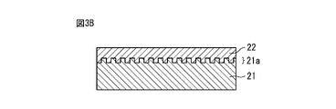
図3Aは他の実施形態における第一基材の側面図である。図3Aに示される第一基材21はその表面に複数の微細な凹凸部21aが形成されている。このような凹凸部21aは前述した溝Aおよび凹部Bよりもかなり小型であるものとする。
仮接着ユニット11の温度T1は第二基材22の第二ガラス転移温度Tg2よりも高いので、仮接着時に第二基材22が軟化して第二基材22が第一基材21の凹凸部21a内に入り込むようになる。これにより、仮接着工程の時間を短くしても、強固な接着作用がえられるのが分かるであろう。なお、凹凸部21aは第一基材21の作成時、例えば射出成形時に同時に形成されてもよく、第一基材21の作成後に形成するようにしてもよい。
実施例1
実施例1
表1に示される第一基材21および第二基材22を準備した。第一基材21はシクロオレフィンポリマ(COP)製であり、第一ガラス転移温度Tg1は100℃、厚さは1.2mmである。第二基材22はシクロオレフィンコポリマ(COC)製であり、第二ガラス転移温度Tg2は78℃、厚さは0.1mmである。また、第一基材21の凹部Bに試薬を予め充填した。比較例1、2の場合も同様である。

表2に示されるように実施例1の仮接着工程においては、温度T1を90℃、圧力を4.4MPa、時間を120秒に設定すると共に、本接着工程においては、温度T2を80℃、時間を2時間に設定した。さらに、比較例1、2の仮接着工程においては、温度T1を90℃、圧力を8MPa、時間を120秒に設定すると共に、本接着工程は行わなかった。また、比較例2では、仮接着工程の前に真空紫外光により表面改質処理を行っている。なお、仮接着ユニット11としてプレス機を使用すると共に、本接着ユニット12として恒温槽を使用した。

このようにして作成された実施例1、比較例1、2の接着物を加速試験の観点で42℃で別途加温した。実施例1では、48時間以上経過後も、凹部Bに充填された試薬は漏洩しなかった。比較例1では、1~10時間(複数サンプルのばらつきや同じサンプル内での凹部位置によるばらつき)経過すると、凹部Bに充填された試薬は漏洩した。比較例2では、1~6時間経過すると、凹部Bに充填された試薬は漏洩した。従って、本開示においては、耐水性の高いオレフィン系の接着物を提供することができる。
実施例2
実施例2
図4Aは実施例2における第一基材および第二基材の部分側面図である。第一基材21および第二基材22は表1における実施例1の場合と同様である。また、第一基材21に形成された凹部Bの深さは0.7mmである。
表1に示される実施例1の条件で仮接着工程が行われると、図4Aに示されるように第二基材22が第一基材21の凹部B内に部分的に落ち込むようになる。凹部Bに対応した位置に在る第二基材22の上面の落ち込み量をZとする。落ち込み易さは接着条件や材質の特性によって変わる。
図4Bは本接着工程の時間と第二基材の落ち込み量との間の関係を示す図である。図4Bに示されるように、仮接着工程直後(本接着工程の時間ゼロ)においては落ち込み量Zは約0.11mmである。そして、表1に示される実施例1の条件で本接着工程を行う。本接着工程を少なくとも2時間行うと、落ち込み量Zは0.02mmとなり、落ち込みが概ね解消されていることが分かる。
なお、実施例2における本接着工程の時間は、落ち込み量Zが概ね解消されると共に、耐水性(表2参照)を満たす時間であるのが望ましい。
また、実施例1、2においては第一基材21の第一樹脂および第二基材22の第二樹脂はオレフィン系ポリマである。具体的には、第一樹脂はシクロオレフィンポリマ(COP)であり、第二樹脂はシクロオレフィンコポリマ(COC)である。この場合には、特にオレフィン系ポリマが有用とされる光学部材や医療用包装などのデバイスの接着に適用することが可能となる。
当然のことながら、第一ガラス転移温度Tg1と第二ガラス転移温度Tg2との間の関係(Tg1>Tg2)を満たす他の二種類の樹脂を第一樹脂および第二樹脂として採用することもできる。或いは、ガラス転移温度が互いに異なっていれば、仕様、例えば分子量の異なる同一種類の樹脂、例えばシクロオレフィンポリマを第一樹脂および第二樹脂として使用してもよい。さらに、第一ガラス転移温度Tg1と第二ガラス転移温度Tg2との間の関係(Tg1>Tg2)を満たす場合には、第一樹脂としてシクロオレフィンコポリマ(COC)を選択すると共に、第二樹脂としてシクロオレフィンポリマ(COP)を選択してもよい。また、本開示における基材接着方法および/または基材接着システムにより接着された第一基材および第二基材を含むマイクロ流体デバイスは本開示の範囲に含まれる。
以上、本発明の実施形態を説明したが、後述する請求の範囲の開示範囲から逸脱することなく様々な修正及び変更を為し得ることは、当業者に理解されよう。
10 基材接着システム
11 仮接着ユニット
12 本接着ユニット
21 第一基材
21a 凹凸部
22 第二基材
11 仮接着ユニット
12 本接着ユニット
21 第一基材
21a 凹凸部
22 第二基材
Claims (8)
- 第一ガラス転移温度を有する第一樹脂からなる第一基材と、前記第一ガラス転移温度よりも低い第二ガラス転移温度を有する第二樹脂からなる第二基材とを準備する準備工程と、
前記第一基材に前記第二基材を重畳させて所定温度で且つ所定圧力で互いに圧着する仮接着工程と、を含み、前記所定温度は前記第一ガラス転移温度と前記第二ガラス転移温度との間の温度であり、
さらに、
前記互いに圧着された前記第一基材および前記第二基材を前記第二ガラス転移温度に概ね等しい温度で所定時間に亙って加熱する本接着工程を含む、基材接着方法。 - 前記本接着工程においては前記第一基材および前記第二基材を圧着しないようにした、請求項1に記載の基材接着方法。
- 前記所定温度と前記第一ガラス転移温度との差は5℃以上、好ましくは10℃以上であり、且つ
前記所定温度と前記第二ガラス転移温度との差は5℃以上、好ましくは10℃以上であるようにした、請求項1または2に記載の基材接着方法。 - 前記第一ガラス転移温度と前記第二ガラス転移温度との差は10℃~40℃、好ましくは20℃~30℃であるようにした、請求項1から3のいずれか一項に記載の基材接着方法。
- 前記第二基材に接触する前記第一基材の表面には、溝および凹部のうちの少なくとも一方が形成されている、請求項1から4のいずれか一項に記載の基材接着方法。
- 前記第一樹脂はシクロオレフィンポリマおよびシクロオレフィンコポリマのうちの一方であり、前記第二樹脂はシクロオレフィンポリマおよびシクロオレフィンコポリマのうちの他方である、請求項1から5のいずれか一項に記載の基材接着方法。
- 第一ガラス転移温度を有する第一樹脂からなる第一基材に、前記第一ガラス転移温度よりも低い第二ガラス転移温度を有する第二樹脂からなる第二基材を重畳させて所定温度で且つ所定圧力で互いに圧着する仮接着ユニット、を具備し、前記所定温度は前記第一ガラス転移温度と前記第二ガラス転移温度との間の温度であり、
さらに、
前記互いに圧着された前記第一基材および前記第二基材を前記第二ガラス転移温度に概ね等しい温度で所定時間に亙って加熱する本接着ユニットを具備する、基材接着システム。 - 前記第一樹脂はシクロオレフィンポリマおよびシクロオレフィンコポリマのうちの一方であり、前記第二樹脂はシクロオレフィンポリマおよびシクロオレフィンコポリマのうちの他方であり、
請求項1から6のいずれか一項に記載の基材接着方法により互いに接着された前記第一基材および前記第二基材を含むマイクロ流体デバイス。
Priority Applications (1)
| Application Number | Priority Date | Filing Date | Title |
|---|---|---|---|
| JP2022580622A JPWO2022172898A1 (ja) | 2021-02-10 | 2022-02-07 |
Applications Claiming Priority (2)
| Application Number | Priority Date | Filing Date | Title |
|---|---|---|---|
| JP2021019614 | 2021-02-10 | ||
| JP2021-019614 | 2021-02-10 |
Publications (1)
| Publication Number | Publication Date |
|---|---|
| WO2022172898A1 true WO2022172898A1 (ja) | 2022-08-18 |
Family
ID=82837871
Family Applications (1)
| Application Number | Title | Priority Date | Filing Date |
|---|---|---|---|
| PCT/JP2022/004729 WO2022172898A1 (ja) | 2021-02-10 | 2022-02-07 | 基材接着方法、基材接着システムおよびマイクロ流体デバイス |
Country Status (2)
| Country | Link |
|---|---|
| JP (1) | JPWO2022172898A1 (ja) |
| WO (1) | WO2022172898A1 (ja) |
Citations (3)
| Publication number | Priority date | Publication date | Assignee | Title |
|---|---|---|---|---|
| JP2003211545A (ja) * | 2002-01-29 | 2003-07-29 | Mitsui Chemicals Inc | フレキシブル両面金属積層板の製造方法 |
| JP2013010076A (ja) * | 2011-06-29 | 2013-01-17 | Sumitomo Bakelite Co Ltd | マイクロ流路デバイスの製造方法及びマイクロ流路チップ |
| JP2020011403A (ja) * | 2018-07-13 | 2020-01-23 | サムコ株式会社 | シクロオレフィンポリマーの接合方法 |
-
2022
- 2022-02-07 WO PCT/JP2022/004729 patent/WO2022172898A1/ja active Application Filing
- 2022-02-07 JP JP2022580622A patent/JPWO2022172898A1/ja active Pending
Patent Citations (3)
| Publication number | Priority date | Publication date | Assignee | Title |
|---|---|---|---|---|
| JP2003211545A (ja) * | 2002-01-29 | 2003-07-29 | Mitsui Chemicals Inc | フレキシブル両面金属積層板の製造方法 |
| JP2013010076A (ja) * | 2011-06-29 | 2013-01-17 | Sumitomo Bakelite Co Ltd | マイクロ流路デバイスの製造方法及びマイクロ流路チップ |
| JP2020011403A (ja) * | 2018-07-13 | 2020-01-23 | サムコ株式会社 | シクロオレフィンポリマーの接合方法 |
Also Published As
| Publication number | Publication date |
|---|---|
| JPWO2022172898A1 (ja) | 2022-08-18 |
Similar Documents
| Publication | Publication Date | Title |
|---|---|---|
| US7442581B2 (en) | Flexible carrier and release method for high volume electronic package fabrication | |
| KR101985639B1 (ko) | 기판의 부착 방법 및 마이크로칩의 제조 방법 | |
| WO2013118447A1 (ja) | 流体取扱装置およびその製造方法 | |
| US20120018084A1 (en) | Printed Circuit Board Assembly Manufacturing Device And Method | |
| JP2001085083A (ja) | Cog実装品および接続材料 | |
| Dragoi et al. | Wafer-level plasma activated bonding: new technology for MEMS fabrication | |
| JP6807585B2 (ja) | 構造体の製造方法及び構造体 | |
| KR20160047184A (ko) | 미세섬모 구조물의 제조방법 및 미세섬모 구조물 | |
| WO2022172898A1 (ja) | 基材接着方法、基材接着システムおよびマイクロ流体デバイス | |
| JP2019214714A5 (ja) | ||
| EP3615318B1 (en) | Method for manufacturing an optical article | |
| US5240549A (en) | Fixture and method for attaching components | |
| US20110180211A1 (en) | Method for Joining Two Components | |
| KR20170044216A (ko) | 첩부 방법 및 첩부 장치 | |
| US8691039B2 (en) | Method and device for thermocompression bonding | |
| CN101003191A (zh) | 复合片材 | |
| WO2008050791A1 (en) | Microchip plate and process for producing the same | |
| Svedberg et al. | On the integration of flexible circuit boards with hot embossed thermoplastic structures for actuator purposes | |
| FR2586251A1 (fr) | Procede de liaison de surfaces planes par l'usage de substances adhesives a l'etat pateux ou sous forme de pellicule non-seche | |
| US11167284B2 (en) | Substrate assembly and method of bonding substrates | |
| JPH0425142A (ja) | 半導体素子の実装方法 | |
| JP6815172B2 (ja) | 接合部材、接合部材の製造方法、中空部材、電子・電気部品、センサハウジングおよびセンサ | |
| JP6663074B2 (ja) | 流路チップ及び流路チップの製造方法 | |
| JP4942094B2 (ja) | 電極付きガラス製マイクロチップ基板の製造方法 | |
| JP2022026113A (ja) | 積層体の製造方法 |
Legal Events
| Date | Code | Title | Description |
|---|---|---|---|
| 121 | Ep: the epo has been informed by wipo that ep was designated in this application |
Ref document number: 22752721 Country of ref document: EP Kind code of ref document: A1 |
|
| ENP | Entry into the national phase |
Ref document number: 2022580622 Country of ref document: JP Kind code of ref document: A |
|
| NENP | Non-entry into the national phase |
Ref country code: DE |
|
| 122 | Ep: pct application non-entry in european phase |
Ref document number: 22752721 Country of ref document: EP Kind code of ref document: A1 |