EP3399397A1 - Drive controlling apparatus and drive controlling method - Google Patents
Drive controlling apparatus and drive controlling method Download PDFInfo
- Publication number
- EP3399397A1 EP3399397A1 EP18179416.5A EP18179416A EP3399397A1 EP 3399397 A1 EP3399397 A1 EP 3399397A1 EP 18179416 A EP18179416 A EP 18179416A EP 3399397 A1 EP3399397 A1 EP 3399397A1
- Authority
- EP
- European Patent Office
- Prior art keywords
- manipulation input
- drive controlling
- vibrating element
- natural vibration
- top panel
- Prior art date
- Legal status (The legal status is an assumption and is not a legal conclusion. Google has not performed a legal analysis and makes no representation as to the accuracy of the status listed.)
- Withdrawn
Links
Images


Classifications
-
- G—PHYSICS
- G06—COMPUTING OR CALCULATING; COUNTING
- G06F—ELECTRIC DIGITAL DATA PROCESSING
- G06F3/00—Input arrangements for transferring data to be processed into a form capable of being handled by the computer; Output arrangements for transferring data from processing unit to output unit, e.g. interface arrangements
- G06F3/01—Input arrangements or combined input and output arrangements for interaction between user and computer
- G06F3/03—Arrangements for converting the position or the displacement of a member into a coded form
- G06F3/041—Digitisers, e.g. for touch screens or touch pads, characterised by the transducing means
-
- G—PHYSICS
- G06—COMPUTING OR CALCULATING; COUNTING
- G06F—ELECTRIC DIGITAL DATA PROCESSING
- G06F3/00—Input arrangements for transferring data to be processed into a form capable of being handled by the computer; Output arrangements for transferring data from processing unit to output unit, e.g. interface arrangements
- G06F3/01—Input arrangements or combined input and output arrangements for interaction between user and computer
- G06F3/016—Input arrangements with force or tactile feedback as computer generated output to the user
Definitions
- an object of the present invention is to provide a drive controlling apparatus, an electronic device and a drive controlling method that can provide a fine or crisp tactile sensation to a user.
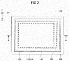
- FIG. 2 is a diagram illustrating the electronic device 100 of the embodiment in plan view.
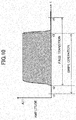
- FIG. 3 is a diagram illustrating a cross-sectional view of the electronic device 100 taken along a line A-A of FIG. 2 .
- An XYZ coordinate system as an orthogonal coordinate system is defined in FIGS. 2 and 3 .
- the housing 110 is made of a plastic, for example. As illustrated in FIG. 3 , the substrate 170, the display panel 160 and the touch panel 150 are contained in a concave portion 110A of the housing 110, and a top panel 120 is adhered onto the housing 110 by the double-faced adhesive tape 130.
- the ultrasound-frequency-band is a frequency band which is higher than or equal to about 20 kHz, for example.
- the frequency at which the vibrating element 140 vibrates is equal to a number of vibrations per unit time (frequency) of the top panel 120. Accordingly, the vibrating element 140 is driven in accordance with the driving signal so that the vibrating element 140 vibrates at a number of natural vibrations per unit time (natural vibration frequency) of the top panel 120.
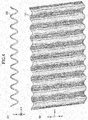
- the areas in which the fingertip touches while the vibration is turned off are indicated in grey in the direction from the far side to the near side.
- the areas in which the fingertip touches while the vibration is turned on are indicated in white in the direction from the far side to the near side.
- a layer of air intervenes between the surface of the top panel 120 and the fingertip.
- the layer of air is provided by a squeeze film effect.
- a kinetic friction coefficient on the surface of the top panel 120 is decreased when the user traces the surface with the fingertip.
- the electronic device 100 includes the vibrating element 140, an amplifier 141, the touch panel 150, a driver Integrated Circuit (IC) 151, the display panel 160, a driver IC 161, a controller 200, a sinusoidal wave generator 310 and a amplitude modulator 320.
- IC Integrated Circuit
- the drive controlling part 240 outputs an amplitude data to the amplitude modulator 320 in a case where two designated condition are satisfied.
- the amplitude data represents an amplitude value used for controlling an intensity of the driving signal used for driving the vibrating element 140.
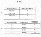
- the amplitude value is set in accordance with a temporal change degree of the position data.
- a moving speed of the user's fingertip tracing along the surface of the top panel 120 is used as the temporal change degree of the position data.
- the drive controlling part 240 calculates the moving speed of the user's fingertip based on a temporal change degree of the position data input from the driver IC 151.
- the amplitude data is output to the amplitude modulator 320 in a case where the position of the fingertip performing the manipulation input is in a designated area which requires generating the vibration.
- a second designated condition is satisfied in a case where the position of the fingertip performing the manipulation input is in the designated area which requires generating the vibration.
- a swipe operation is performed, for example.
- the swipe operation is performed by swiping the fingertip along the surface of the top panel 120 for a relatively-long distance.
- the swipe operation is performed when the user turns over or flips the page or a photo, for example.
- a drag operation is performed when the user slides the slider (see the slider 102B as illustrated in FIG. 1 ) which is constituted by the GUI input part.
- the drive controlling part 240 performs a calculation for estimating the coordinate point after a lapse of the required period of time ⁇ t as described above.
- the drive controlling part 240 determines whether the estimated coordinate point is located in the designated area which requires generating the vibration and generates the vibration if the estimated coordinate point is located in the designated area. Accordingly, the second designated condition is that the estimated coordinate point is located in the designated area which requires generating the vibration.
- the two designated conditions required for the drive controlling part 240 to output the amplitude data to the amplitude modulator 320 are that the moving speed of the fingertip is more than or equal to the designated threshold speed and that the estimated coordinate point is located in the designated area which requires generating the vibration.
- application program ID (Identification) is illustrated as the data representing the kind of the application program.
- Formulas f1 to f4 representing the coordinate values of the GUI input parts or the like to which the manipulation inputs are performed are illustrated as the area data.
- P1 to P4 are illustrated as the pattern data representing the vibration patterns.
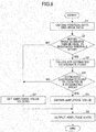
- FIG. 8 is a diagram illustrating a flowchart executed by the drive controlling part 240 of the drive controlling apparatus 300 included in the electronic device 100 according to the embodiment.
- An operating system (OS) of the electronic device 100 executes drive controls of the electronic device 100 every designated control cycle. Accordingly, the drive controlling apparatus 300 performs the processing every designated control cycle. The same applies to the drive controlling part 240.
- the drive controlling part 240 executes the flows as illustrated in FIG. 8 every designated control cycle.
- the required period of time ⁇ t is almost equal to a period of the single control cycle.
- a period of time of one cycle of the control cycle can be treated as a period of time corresponding to the required period of time ⁇ t which is required from the point in time when the position data is input to the drive controlling apparatus 300 from the driver IC 151 to the point in time when the driving signal is calculated based on the position data.
- the drive controlling part 240 obtains the coordinate values represented by the present position data and the area data associated with the vibration pattern with respect to the GUI input part to which the manipulation input is being performed in accordance with the kind of the present application program (step S1).
- the amplitude of the vibration pattern prepared for the swipe operation is A11.
- the vibration pattern prepared for the swipe operation has a driving pattern in which the vibration continues while the swipe operation is being performed.
- the drive controlling part 240 determines whether the manipulation input is the flick operation.
- the vibration is generated in the top panel 120 as follows.
- the user touches the position C11 located above alphabet "j" with the fingertip at time point t11 and begins to move the fingertip in a positive Y axis direction at time point t12.
- the vibration is generated right after being determined that the fingertip is moved from the position C11.
- the slippery or smooth touch is provided to the user through the fingertip.
- the user can recognize that the manipulation input which is performed by moving the fingertip on alphabet "j" is accepted by the electronic device 100 through the fingertip. Since the natural vibration is generated in the top panel 120 in this situation, the user's fingertip is in a slippery condition. Therefore, it is easy to perform the flick operation.
- the amplitude of the top panel 120 becomes zero.
- the kinetic friction force applied to the user's fingertip becomes greater, and the grippy or scratchy touch (texture) is provided to the user through the fingertip. Since the kinetic friction force becomes greater as described above, the user senses as if the user touches the convex portion.
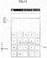
- FIGS. 11 and 12 A case where the GUI input part used for inputting "j", “k”, “1”, “5" or “&” is used is described with reference to FIGS. 11 and 12 .
- the vibration may be generated every time the length of the move reaches a designated length. Otherwise, the top panel 120 may be vibrated in any vibration pattern in order to cause the user to sense the operation of the slider 102B.
- the user touches a numeral '6' with the fingertip, begins to move the fingertip along the surface of the top panel 120 leftward and traces numerals "5" and "4" in this order. If the user performs the manipulation input as described above, the vibration is generated in the top panel 120 as follows. Such a manipulation input is different from the flick operation, the swipe operation and the drag operation.
- the manipulation input is a type of a manipulation input which is performed while the fingertip is moving across a plurality of the GUI input parts in a condition where the plurality of the GUI input parts are arranged.
- the generation of the vibration B11 results from the positional change of the fingertip which comes out of the area of numeral "6".
- the sense of touching the convex portion is provided to the user through the fingertip by changing a condition of the manipulation input surface from a low-friction-condition over the short amount of time to a high-friction-condition instantaneously.
- the electronic device 100 Since the electronic device 100 generates the vibration in a case where the estimated coordinate point after the lapse of the required period of time ⁇ t corresponding to the period of time of one cycle of the control cycle is located in the designated area which requires generating the vibration, it becomes possible to generate the vibration while the fingertip is touching the designated GUI input part or the like.
- the electronic device 100 may not perform the calculation of the estimated coordinate.
- the vibrating element 140 is switched on or off. Turning off the vibrating element 140 is equal to setting the amplitude value represented by the driving signal used for driving the vibrating element 140 to zero.
- the vibrating element 140 is driven based on the driving signal having a small amplitude instead of turning off the vibrating element 140.
- the electronic device 100 may provide the sense as if the concavity or the convexity is existing on the surface of the top panel 120 by reducing the amplitude to about one-fifth of that of the turned on state.
- the vibrating element 140 is switched off. Switching on and off the vibrating element 140 means driving the vibrating element 140 intermittently.
- the drive controlling apparatus 300, the electronic device 100 and the drive controlling method that can provide the fine or crisp tactile sensation to the user are provided.
Landscapes
- Engineering & Computer Science (AREA)
- General Engineering & Computer Science (AREA)
- Theoretical Computer Science (AREA)
- Human Computer Interaction (AREA)
- Physics & Mathematics (AREA)
- General Physics & Mathematics (AREA)
- User Interface Of Digital Computer (AREA)
- Position Input By Displaying (AREA)
Priority Applications (1)
| Application Number | Priority Date | Filing Date | Title |
|---|---|---|---|
| EP18179416.5A EP3399397A1 (en) | 2013-09-26 | 2013-09-26 | Drive controlling apparatus and drive controlling method |
Applications Claiming Priority (3)
| Application Number | Priority Date | Filing Date | Title |
|---|---|---|---|
| EP18179416.5A EP3399397A1 (en) | 2013-09-26 | 2013-09-26 | Drive controlling apparatus and drive controlling method |
| EP13874859.5A EP2876533A4 (en) | 2013-09-26 | 2013-09-26 | DRIVE CONTROL DEVICE, ELECTRONIC DEVICE AND DRIVE CONTROL PROCEDURE |
| PCT/JP2013/076054 WO2015045059A1 (ja) | 2013-09-26 | 2013-09-26 | 駆動制御装置、電子機器、及び駆動制御方法 |
Related Parent Applications (1)
| Application Number | Title | Priority Date | Filing Date |
|---|---|---|---|
| EP13874859.5A Division EP2876533A4 (en) | 2013-09-26 | 2013-09-26 | DRIVE CONTROL DEVICE, ELECTRONIC DEVICE AND DRIVE CONTROL PROCEDURE |
Publications (1)
| Publication Number | Publication Date |
|---|---|
| EP3399397A1 true EP3399397A1 (en) | 2018-11-07 |
Family
ID=51935071
Family Applications (2)
| Application Number | Title | Priority Date | Filing Date |
|---|---|---|---|
| EP18179416.5A Withdrawn EP3399397A1 (en) | 2013-09-26 | 2013-09-26 | Drive controlling apparatus and drive controlling method |
| EP13874859.5A Ceased EP2876533A4 (en) | 2013-09-26 | 2013-09-26 | DRIVE CONTROL DEVICE, ELECTRONIC DEVICE AND DRIVE CONTROL PROCEDURE |
Family Applications After (1)
| Application Number | Title | Priority Date | Filing Date |
|---|---|---|---|
| EP13874859.5A Ceased EP2876533A4 (en) | 2013-09-26 | 2013-09-26 | DRIVE CONTROL DEVICE, ELECTRONIC DEVICE AND DRIVE CONTROL PROCEDURE |
Country Status (11)
| Country | Link |
|---|---|
| US (1) | US9400571B2 (cs) |
| EP (2) | EP3399397A1 (cs) |
| JP (1) | JP5780368B1 (cs) |
| KR (1) | KR101516926B1 (cs) |
| CN (1) | CN104662495B (cs) |
| AU (1) | AU2013378679B8 (cs) |
| BR (2) | BR122014032444A2 (cs) |
| IN (1) | IN2014KN01684A (cs) |
| MX (2) | MX351158B (cs) |
| SG (1) | SG11201404795WA (cs) |
| WO (1) | WO2015045059A1 (cs) |
Cited By (1)
| Publication number | Priority date | Publication date | Assignee | Title |
|---|---|---|---|---|
| CN113965633A (zh) * | 2021-09-23 | 2022-01-21 | 昆山峰实电子外观应用科技有限公司 | 一种触碰震动产品及生产方法 |
Families Citing this family (37)
| Publication number | Priority date | Publication date | Assignee | Title |
|---|---|---|---|---|
| WO2015045063A1 (ja) | 2013-09-26 | 2015-04-02 | 富士通株式会社 | 駆動制御装置、電子機器、及び駆動制御方法 |
| JP6010012B2 (ja) * | 2013-12-03 | 2016-10-19 | 富士フイルム株式会社 | 導電シート、静電容量式タッチパネル及び表示装置 |
| WO2015121956A1 (ja) | 2014-02-14 | 2015-08-20 | 富士通株式会社 | 電子機器及び駆動制御方法 |
| JPWO2015121955A1 (ja) * | 2014-02-14 | 2017-03-30 | 富士通株式会社 | 電子機器、入力装置、及び駆動制御方法 |
| WO2015121970A1 (ja) | 2014-02-14 | 2015-08-20 | 富士通株式会社 | 教育用触感提供装置、及び、システム |
| FR3029435B1 (fr) * | 2014-12-08 | 2019-11-15 | Institut Polytechnique De Grenoble | Dispositif vibrant comportant des reflecteurs mecaniques encastres pour definir une zone active de propagation de modes de plaque et appareil mobile comportant le dispositif |
| WO2016157491A1 (ja) * | 2015-04-02 | 2016-10-06 | 富士通株式会社 | 電子機器、座標検出ユニット、及び、接着部材 |
| JP6447719B2 (ja) * | 2015-04-21 | 2019-01-09 | 富士通株式会社 | 電子機器 |
| JP2016207128A (ja) * | 2015-04-28 | 2016-12-08 | 富士通株式会社 | 入力装置、及び、電子機器 |
| WO2016174760A1 (ja) * | 2015-04-30 | 2016-11-03 | 富士通株式会社 | 駆動制御装置、電子機器、駆動制御プログラム、及び駆動制御方法 |
| JPWO2016178289A1 (ja) * | 2015-05-07 | 2018-02-22 | 富士通株式会社 | 電子機器及び振動制御プログラム |
| WO2016208036A1 (ja) * | 2015-06-25 | 2016-12-29 | 富士通株式会社 | 電子機器、及び、駆動制御方法 |
| WO2017017835A1 (ja) * | 2015-07-30 | 2017-02-02 | 富士通株式会社 | マウス装置 |
| JP6512299B2 (ja) * | 2015-08-19 | 2019-05-15 | 富士通株式会社 | 駆動制御装置、電子機器、駆動制御プログラム、及び駆動制御方法 |
| US20170060241A1 (en) * | 2015-08-26 | 2017-03-02 | Fujitsu Ten Limited | Input device, display device, method of controlling input device, and program |
| KR101606791B1 (ko) * | 2015-09-08 | 2016-03-28 | 박재성 | 주파수 변화에 따라 실시간 진동을 제공하는 진동 제공시스템 및 이것의 진동 제공방법 |
| JP6676913B2 (ja) * | 2015-09-30 | 2020-04-08 | ブラザー工業株式会社 | 情報処理装置、および制御プログラム |
| JP2017072901A (ja) * | 2015-10-05 | 2017-04-13 | 株式会社東海理化電機製作所 | 触覚呈示装置 |
| CN105426024B (zh) * | 2015-11-25 | 2018-03-27 | 吉林大学 | 一种基于超声波聚焦的触觉反馈系统及方法 |
| US10001882B2 (en) * | 2015-12-02 | 2018-06-19 | Rapt Ip Limited | Vibrated waveguide surface for optical touch detection |
| CN108292177B (zh) | 2015-12-09 | 2021-01-26 | 富士通株式会社 | 电子设备 |
| JP7043166B2 (ja) * | 2016-09-21 | 2022-03-29 | 株式会社デンソーテン | 表示制御装置、表示制御システム及び表示制御方法 |
| WO2018134938A1 (ja) * | 2017-01-19 | 2018-07-26 | 富士通株式会社 | 電子機器 |
| JP2018133021A (ja) | 2017-02-17 | 2018-08-23 | 富士通コンポーネント株式会社 | 触感提示装置及びタッチパネル |
| WO2018164321A1 (ko) * | 2017-03-09 | 2018-09-13 | 한양대학교 산학협력단 | 초음파를 이용하는 촉감 제공 장치 및 촉감 디스플레이 장치 |
| GB2561883A (en) * | 2017-04-27 | 2018-10-31 | Cambridge Touch Tech Ltd | Touchscreen panel haptics |
| CN107704075A (zh) * | 2017-09-01 | 2018-02-16 | 惠州市德赛西威汽车电子股份有限公司 | 一种触控面板振动反馈装置 |
| JP7087367B2 (ja) | 2017-12-08 | 2022-06-21 | 富士フイルムビジネスイノベーション株式会社 | 情報処理装置、プログラム及び制御方法 |
| WO2019130504A1 (ja) * | 2017-12-27 | 2019-07-04 | 富士通株式会社 | 電子機器 |
| CN108363993B (zh) * | 2018-03-15 | 2020-12-04 | 京东方科技集团股份有限公司 | 指纹识别模组、显示装置及其制作方法 |
| JP7114309B2 (ja) * | 2018-04-16 | 2022-08-08 | キヤノン株式会社 | 電子機器および電子機器の制御方法 |
| JP2020042609A (ja) | 2018-09-12 | 2020-03-19 | 富士通コンポーネント株式会社 | 触感提示装置 |
| US11086431B2 (en) | 2019-01-30 | 2021-08-10 | Samsung Display Co., Ltd. | Display device and method for providing haptic feedback by display device |
| JP7370190B2 (ja) | 2019-08-14 | 2023-10-27 | 太陽誘電株式会社 | パネル及び電子機器 |
| US11249576B2 (en) * | 2019-12-09 | 2022-02-15 | Panasonic Intellectual Property Management Co., Ltd. | Input device generating vibration at peripheral regions of user interfaces |
| TWI770949B (zh) | 2021-04-20 | 2022-07-11 | 達運精密工業股份有限公司 | 顯示裝置、非接觸式按鍵及輸入裝置 |
| CN115639918A (zh) * | 2021-07-20 | 2023-01-24 | 北京京东方技术开发有限公司 | 显示装置 |
Citations (5)
| Publication number | Priority date | Publication date | Assignee | Title |
|---|---|---|---|---|
| WO2007111909A2 (en) * | 2006-03-24 | 2007-10-04 | Northwestern University | Haptic device with indirect haptic feedback |
| US20090284485A1 (en) * | 2007-03-21 | 2009-11-19 | Northwestern University | Vibrating substrate for haptic interface |
| JP2010231609A (ja) | 2009-03-27 | 2010-10-14 | Hitachi Maxell Ltd | 触感呈示装置及び方法 |
| US20120256858A1 (en) * | 2011-04-07 | 2012-10-11 | Kyocera Corporation | Character input device, character-input control method, and storage medium storing character input program |
| WO2013108595A1 (ja) * | 2012-01-17 | 2013-07-25 | パナソニック株式会社 | 電子機器 |
Family Cites Families (22)
| Publication number | Priority date | Publication date | Assignee | Title |
|---|---|---|---|---|
| JP3949912B2 (ja) | 2000-08-08 | 2007-07-25 | 株式会社エヌ・ティ・ティ・ドコモ | 携帯型電子機器、電子機器、振動発生器、振動による報知方法および報知制御方法 |
| JP4199480B2 (ja) | 2002-04-24 | 2008-12-17 | トヨタ自動車株式会社 | 入力装置 |
| JP4046095B2 (ja) * | 2004-03-26 | 2008-02-13 | ソニー株式会社 | 触覚機能付き入力装置、情報入力方法及び電子機器 |
| EP1805585B1 (en) | 2004-10-08 | 2017-08-16 | Immersion Corporation | Haptic feedback for button and scrolling action simulation in touch input devices |
| JP4694579B2 (ja) | 2007-04-11 | 2011-06-08 | 株式会社フェイビー | 文字入力システム |
| US8098235B2 (en) | 2007-09-28 | 2012-01-17 | Immersion Corporation | Multi-touch device having dynamic haptic effects |
| JP4875050B2 (ja) * | 2008-12-09 | 2012-02-15 | 京セラ株式会社 | 入力装置 |
| JP5343871B2 (ja) | 2009-03-12 | 2013-11-13 | 株式会社リコー | タッチパネル装置、これを含むタッチパネル付き表示装置、及びタッチパネル装置の制御方法 |
| WO2010105012A1 (en) * | 2009-03-12 | 2010-09-16 | Immersion Corporation | Systems and methods for a texture engine |
| JP4522475B1 (ja) | 2009-03-19 | 2010-08-11 | Smk株式会社 | 操作入力装置、制御方法、およびプログラム |
| JP4778591B2 (ja) | 2009-05-21 | 2011-09-21 | パナソニック株式会社 | 触感処理装置 |
| KR101719507B1 (ko) * | 2009-11-17 | 2017-03-24 | 임머숀 코퍼레이션 | 전자 디바이스에서 촉각 대역폭을 증가시키는 시스템들 및 방법들 |
| KR101649206B1 (ko) * | 2009-12-22 | 2016-08-18 | 엘지디스플레이 주식회사 | 터치 스크린 장치 |
| US9501145B2 (en) * | 2010-05-21 | 2016-11-22 | Disney Enterprises, Inc. | Electrovibration for touch surfaces |
| JP5630119B2 (ja) * | 2010-07-26 | 2014-11-26 | 株式会社リコー | タッチパネル装置、これを含むタッチパネル付き表示装置、及びタッチパネル装置の制御方法 |
| JP5689362B2 (ja) * | 2011-05-23 | 2015-03-25 | 株式会社東海理化電機製作所 | 入力装置 |
| KR101503454B1 (ko) * | 2011-07-19 | 2015-03-18 | 광주과학기술원 | 진동촉각 제공 방법 및 장치 |
| JP5834302B2 (ja) | 2011-09-29 | 2015-12-16 | 株式会社ユピテル | 文字入力システム及びプログラム |
| JP2013097438A (ja) * | 2011-10-28 | 2013-05-20 | Mitsubishi Electric Corp | 触覚提示装置 |
| JP2013156682A (ja) * | 2012-01-26 | 2013-08-15 | Kddi Corp | 不可聴振動によって事象発動を通知するユーザインタフェース装置、事象発動通知方法及びプログラム |
| US9330544B2 (en) * | 2012-11-20 | 2016-05-03 | Immersion Corporation | System and method for simulated physical interactions with haptic effects |
| WO2015045063A1 (ja) | 2013-09-26 | 2015-04-02 | 富士通株式会社 | 駆動制御装置、電子機器、及び駆動制御方法 |
-
2013
- 2013-09-26 AU AU2013378679A patent/AU2013378679B8/en not_active Ceased
- 2013-09-26 IN IN1684KON2014 patent/IN2014KN01684A/en unknown
- 2013-09-26 EP EP18179416.5A patent/EP3399397A1/en not_active Withdrawn
- 2013-09-26 BR BR122014032444-8A patent/BR122014032444A2/pt not_active Application Discontinuation
- 2013-09-26 BR BR112014020341-5A patent/BR112014020341B1/pt not_active IP Right Cessation
- 2013-09-26 MX MX2016004959A patent/MX351158B/es unknown
- 2013-09-26 CN CN201380010258.3A patent/CN104662495B/zh not_active Expired - Fee Related
- 2013-09-26 MX MX2014009990A patent/MX338463B/es active IP Right Grant
- 2013-09-26 SG SG11201404795WA patent/SG11201404795WA/en unknown
- 2013-09-26 KR KR1020147022980A patent/KR101516926B1/ko not_active Expired - Fee Related
- 2013-09-26 EP EP13874859.5A patent/EP2876533A4/en not_active Ceased
- 2013-09-26 WO PCT/JP2013/076054 patent/WO2015045059A1/ja active Application Filing
- 2013-09-26 JP JP2014538016A patent/JP5780368B1/ja not_active Expired - Fee Related
-
2014
- 2014-08-07 US US14/453,790 patent/US9400571B2/en not_active Expired - Fee Related
Patent Citations (6)
| Publication number | Priority date | Publication date | Assignee | Title |
|---|---|---|---|---|
| WO2007111909A2 (en) * | 2006-03-24 | 2007-10-04 | Northwestern University | Haptic device with indirect haptic feedback |
| US20090284485A1 (en) * | 2007-03-21 | 2009-11-19 | Northwestern University | Vibrating substrate for haptic interface |
| JP2010231609A (ja) | 2009-03-27 | 2010-10-14 | Hitachi Maxell Ltd | 触感呈示装置及び方法 |
| US20120256858A1 (en) * | 2011-04-07 | 2012-10-11 | Kyocera Corporation | Character input device, character-input control method, and storage medium storing character input program |
| WO2013108595A1 (ja) * | 2012-01-17 | 2013-07-25 | パナソニック株式会社 | 電子機器 |
| US20130285910A1 (en) * | 2012-01-17 | 2013-10-31 | Panasonic Corporation | Electronic device |
Cited By (2)
| Publication number | Priority date | Publication date | Assignee | Title |
|---|---|---|---|---|
| CN113965633A (zh) * | 2021-09-23 | 2022-01-21 | 昆山峰实电子外观应用科技有限公司 | 一种触碰震动产品及生产方法 |
| CN113965633B (zh) * | 2021-09-23 | 2024-03-01 | 昆山峰实电子外观应用科技有限公司 | 一种触碰震动产品及生产方法 |
Also Published As
| Publication number | Publication date |
|---|---|
| AU2013378679B1 (en) | 2015-02-26 |
| BR122014032444A2 (pt) | 2019-08-20 |
| US9400571B2 (en) | 2016-07-26 |
| SG11201404795WA (en) | 2015-05-28 |
| MX338463B (es) | 2016-04-15 |
| AU2013378679B8 (en) | 2015-03-05 |
| JPWO2015045059A1 (ja) | 2017-03-02 |
| US20140347322A1 (en) | 2014-11-27 |
| BR112014020341A2 (cs) | 2017-06-20 |
| MX351158B (es) | 2017-10-04 |
| IN2014KN01684A (cs) | 2015-10-23 |
| WO2015045059A1 (ja) | 2015-04-02 |
| BR112014020341B1 (pt) | 2021-10-19 |
| KR101516926B1 (ko) | 2015-05-04 |
| CN104662495B (zh) | 2017-06-23 |
| EP2876533A1 (en) | 2015-05-27 |
| CN104662495A (zh) | 2015-05-27 |
| JP5780368B1 (ja) | 2015-09-16 |
| EP2876533A4 (en) | 2015-08-19 |
| MX2014009990A (es) | 2015-05-29 |
Similar Documents
| Publication | Publication Date | Title |
|---|---|---|
| US9400571B2 (en) | Drive controlling apparatus, electronic device and drive controlling method | |
| US10031585B2 (en) | Electronic device, drive controlling method, and drive controlling apparatus | |
| US10120484B2 (en) | Drive control apparatus, electronic device and drive controlling method | |
| US20160349846A1 (en) | Electronic device, input apparatus, and drive controlling method | |
| US20180024638A1 (en) | Drive controlling apparatus, electronic device, computer-readable recording medium, and drive controlling method | |
| US20160349847A1 (en) | Electronic device, input apparatus, and drive controlling method | |
| US10042423B2 (en) | Electronic device and drive control method | |
| CN108292177B (zh) | 电子设备 | |
| US20180018022A1 (en) | Electronic device, coordinate detecting unit, and adhesive member | |
| US11086435B2 (en) | Drive control device, electronic device, and drive control method | |
| JP6123850B2 (ja) | 駆動制御装置、電子機器、及び駆動制御方法 | |
| US10359850B2 (en) | Apparatus and method for switching vibration at panel surface | |
| US20160266646A1 (en) | Drive control apparatus, electronic device and drive controlling method | |
| US20180067559A1 (en) | Electronic apparatus and non-transitory recording medium having stored therein | |
| AU2015202408B2 (en) | Drive controlling apparatus, electronic device and drive controlling method | |
| WO2017029717A1 (ja) | 駆動制御装置、電子機器、駆動制御プログラム、及び駆動制御方法 |
Legal Events
| Date | Code | Title | Description |
|---|---|---|---|
| PUAI | Public reference made under article 153(3) epc to a published international application that has entered the european phase |
Free format text: ORIGINAL CODE: 0009012 |
|
| STAA | Information on the status of an ep patent application or granted ep patent |
Free format text: STATUS: THE APPLICATION HAS BEEN PUBLISHED |
|
| AC | Divisional application: reference to earlier application |
Ref document number: 2876533 Country of ref document: EP Kind code of ref document: P |
|
| AK | Designated contracting states |
Kind code of ref document: A1 Designated state(s): AL AT BE BG CH CY CZ DE DK EE ES FI FR GB GR HR HU IE IS IT LI LT LU LV MC MK MT NL NO PL PT RO RS SE SI SK SM TR |
|
| STAA | Information on the status of an ep patent application or granted ep patent |
Free format text: STATUS: REQUEST FOR EXAMINATION WAS MADE |
|
| 17P | Request for examination filed |
Effective date: 20190417 |
|
| RBV | Designated contracting states (corrected) |
Designated state(s): AL AT BE BG CH CY CZ DE DK EE ES FI FR GB GR HR HU IE IS IT LI LT LU LV MC MK MT NL NO PL PT RO RS SE SI SK SM TR |
|
| STAA | Information on the status of an ep patent application or granted ep patent |
Free format text: STATUS: EXAMINATION IS IN PROGRESS |
|
| 17Q | First examination report despatched |
Effective date: 20210325 |
|
| STAA | Information on the status of an ep patent application or granted ep patent |
Free format text: STATUS: THE APPLICATION HAS BEEN WITHDRAWN |
|
| 18W | Application withdrawn |
Effective date: 20210720 |