EP3393324B1 - Auswringvorrichtung für ein wischgerät - Google Patents
Auswringvorrichtung für ein wischgerät Download PDFInfo
- Publication number
- EP3393324B1 EP3393324B1 EP16813237.1A EP16813237A EP3393324B1 EP 3393324 B1 EP3393324 B1 EP 3393324B1 EP 16813237 A EP16813237 A EP 16813237A EP 3393324 B1 EP3393324 B1 EP 3393324B1
- Authority
- EP
- European Patent Office
- Prior art keywords
- receptacle
- holder
- mopping
- wringing
- mop
- Prior art date
- Legal status (The legal status is an assumption and is not a legal conclusion. Google has not performed a legal analysis and makes no representation as to the accuracy of the status listed.)
- Active
Links
Images


Classifications
-
- A—HUMAN NECESSITIES
- A47—FURNITURE; DOMESTIC ARTICLES OR APPLIANCES; COFFEE MILLS; SPICE MILLS; SUCTION CLEANERS IN GENERAL
- A47L—DOMESTIC WASHING OR CLEANING; SUCTION CLEANERS IN GENERAL
- A47L13/00—Implements for cleaning floors, carpets, furniture, walls, or wall coverings
- A47L13/10—Scrubbing; Scouring; Cleaning; Polishing
- A47L13/50—Auxiliary implements
- A47L13/58—Wringers for scouring pads, mops, or the like, combined with buckets
Definitions
- the invention relates to a wringing device for a mopping device, comprising a basket-like receptacle into which the moping device can be wrenched by being pressed, and a holder for fastening the wringing device in a mopping bucket.
- Such a wringing device is for example from DE 102 10 569 A1 famous.
- the EP 2 384 682 A2 describes a wringing device according to the preamble of independent claim 1.
- Such mopping devices are suitable for mops or for flat mops in which the mop cover is attached to the flat mop in such a way that it cannot come off automatically.
- the mopping device is inserted into the receptacle, the mopping cover hanging down in a loop shape from the flat mop for wringing out.
- the receptacle has basket-like or sieve-like recesses so that the water that is pressed out of the mop cover or mop when the mopping device is pressed into the receptacle drips through the openings or recesses of the receptacle into the mop bucket.
- mop covers for flat mops which are made of synthetic textiles, have only a low compressibility.
- the low compressibility leads to a very steep increase in force at the end of the while the mop cover is being pressed into the wringing device Press path.
- the user does not receive any clear feedback regarding the compression of the mop cover, which makes it difficult to correctly dose the pressing force and to achieve the desired degree of wringing out.
- the invention is therefore based on the object of providing a wringing device for a mopping device which can be operated easily and ergonomically.
- the receptacle is guided in the holder in such a way that the receptacle is translationally movable in the insertion direction of the wiper device.
- the receptacle moves, if a mopping device is pressed into the receptacle, translationally in the direction of the floor of the mopping bucket.
- the user has to push the mopping device a larger amount into the receptacle.
- the user receives feedback as to whether the sufficient squeezing force to wring out the mop cover has already been achieved.
- the translational movement of the receptacle is preferably carried out against the force of a spring.
- the egg pressing force increases steadily when the mopping device is pressed into the receptacle.
- the resistance to pressing only increases gradually, so that the wringing out of the mop cover can be very well dosed and the user receives feedback on the extent to which the mop cover has already been wrung out sufficiently.
- a guide is provided which allows the translational movement of the receptacle.
- the guide prevents the mount from tilting or even rotating in the holder. This allows the wiper to be pressed into the receptacle in a defined manner. Furthermore, this results in a stable design of the wringing device.
- the guide can consist of columnar projections and congruent depressions or openings.
- the columnar projections are formed from the holder and the depressions are made in the receptacle. Projections and depressions are designed in such a way that the projections slide along in the depressions when pressed. As a result, only a translational movement of the receptacle relative to the holder is possible.
- the columnar projections are also formed from the holder. Openings through which the projections protrude are made in the receptacle.
- the projections take on two functions in that the projections enable a translational movement of the receptacle relative to the holder and in that the mop pressed into the receptacle is also guided. During the translational movement of the receptacle, the projections slide back and forth in the openings. At the same time, the mop rests against the projections and is guided into the interior of the receptacle.
- This configuration is particularly space-saving due to the lack of depressions, so that the clear width of the receptacle can be increased. As a result, voluminous mops can be wrung out in the wringing device and the mops can be pressed deeper into the receptacle.
- Spring elements are preferably provided which are deformed upon relative movement of the receptacle when the wiper device is pushed in. These cause the translational movement of the receptacle against the force of a spring.
- the spring elements can be provided in the receptacle or in the holder. In an advantageous embodiment, the spring elements are arranged in the holder.
- the spring elements can be made of the same material and in one piece from the holder.
- the spring elements can be provided in the holder in a particularly cost-effective manner. Furthermore, the assembly effort for assembling the wringing device is reduced.
- the spring elements can be assigned stamp bodies which deform the spring body when the receptacle is moved.
- the stamps are preferably designed in such a way that they come to rest against the spring elements as soon as a wiper device is pressed into the receptacle.
- the stamps cause a defined deformation so that clear feedback on the amount of press-in is possible for the user.
- the stamp bodies are assigned either to the receptacle or to the holder.
- visual display means can be provided.
- the holder is provided with a pointer which is assigned to a scale attached to the receptacle. While the mop cover is being pressed in, that is, when the receptacle is moving relative to the holder, the scale slides past the pointer.
- the scale can be provided with markings which, depending on the level of soiling and the type of floor to be cleaned, indicate when the optimum pressing force has been reached. For example, the mop cover for cleaning parquet should be loaded with a smaller amount of liquid, while the amount of liquid used for cleaning of tiles can be larger. Accordingly, a first marking can indicate when the optimum pressing force for tile cleaning is present.
- a second marking can indicate when the optimal pressing force for laminate is present.
- a third marking can indicate when the optimum pressing force for parquet is available. When the third marking is reached, the spring element is almost completely deformed and the receptacle is almost completely moved in the direction of the holder. Correspondingly, maximum wringing out of the mop cover takes place in this position.
- the holder can be held captive in the holder by means of snap hooks.
- the snap hooks are designed in such a way that a translational movement of the receptacle relative to the holder is always possible.
- the snap hooks prevent the receptacle from being completely detached from the holder; the receptacle is thus held captive on the holder by the snap hooks.
- the opening can be assigned a funnel-shaped edge that is higher on one side.
- the higher edge is preferably assigned to the side that faces away from the direction of insertion of the mopping device. This simplifies and improves the insertion of the mopping device and the funnel function of the receptacle.
- a shelf can be assigned to the wringing device.
- the shelf can either be molded into the holder or into the receptacle.
- a simple embodiment of the shelf is formed from a semicircular recess which is molded into the holder or into the receptacle.
- the shelf is used for the temporary fixation of mopping devices.
- the shelf is preferably arranged in such a way that the mopping device can be placed in the mopping bucket and is held there. The filing allows a Safe positioning of the mopping device when it is placed in the mopping bucket.
- the figures show a wringing device 1 for a mopping device.
- the wringing device 1 is designed in such a way that it is preferably suitable for mopping devices in the form of a flat mop with a foldable mopping plate on which a mop cover can be wrung out in the wringing device 1 while hanging down in a loop.
- the wringing device 1 has a basket-like receptacle 2 in which the mopping device can be wringed out by being pressed in.
- the mopping device is inserted into the receptacle 2 for wringing out.
- the mop cover of the mopping device is wrung out by compression and excess water runs through the slots 14 made in the receptacle 2 or other openings from the receptacle 2 into the mop bucket.
- the opening 10 of the receptacle 2 has a rectangular cross section.
- the opening 10 of the receptacle 2 is equipped with a funnel-shaped edge 11 for easier insertion of the mopping device.
- the edge 11 along a longitudinal edge is formed higher on one side.
- the higher section of the edge 11 is assigned to the edge of the mopping bucket and the lower section of the edge 11 is assigned to the center of the mopping bucket.
- the receptacle 2 is assigned to a holder 3, which is equipped for fastening the wringing device 1 in a mop bucket.
- the holder 3 has, at least in sections, a fixing section 13 in the edge area, which in the present embodiment is designed as a bent edge.
- the fixing section 13 is provided with snap locks 16, so that the wringing device 1 can be securely attached to the mop bucket.
- the receptacle 2 is guided in the holder 3 in such a way that the receptacle 2 is translationally movable in the insertion direction of the wiper device.
- a guide 5 is provided which only allows a translational movement of the receptacle 2 relative to the holder 3.
- the guide 5 in the configuration according to FIG Figures 1 to 8 consists of column-like projections 6 and depressions 7 that are congruent to the projections 6.
- the projections 6 are made of the same material and are formed in one piece from the holder 3.
- the recesses 7 are molded into the receptacle 2 of the same material and in one piece.
- the guide 5 in the configuration according to FIG Figures 9 to 12 is formed from columnar projections 6, which are formed from the holder 3 with the same material and in one piece, and from perforations 15 which are made in the receptacle 2 and through which the projections 6 protrude into the interior of the receptacle 2.
- the receptacle 2 remains at a distance from the base of the holder 3 in a first position. During the wringing out, the receptacle 2 moves in the direction of the holder 3 until the receptacle 2 finally comes to rest against stops or the like on the holder 3 in a second position. It is particularly conceivable here that the projections 6 come to rest on the front side against the delimitation of the depressions 7. Overall, the receptacle 2 moves in the direction of the mop bucket during wringing out, while the holder 3 does not change its position relative to the mop bucket.
- the wiper device is pressed into the receptacle 2 against the force of a spring 4.
- spring elements 8 are provided which are deformed when the wiper device is pushed in when the receptacle 2 moves relative to one another.
- the spring elements 8 are made of the same material and are formed in one piece from the holder 3.
- the receptacle 2 openings are made, in which serpentine spring elements 8 are provided.
- the spring elements 8, which are molded into the holder 3, are assigned stamp bodies 9 which deform the spring elements 8 when the receptacle 2 is moved.
- the stamp bodies 9 are made of the same material and are made in one piece from the receptacle 2. During the wringing out, the stamp bodies 9 come to rest on the serpentine spring elements 8, the spring elements 8 being designed in such a way that a central elevation of a spring element 8 interacts with a stamp body 9. In the process, the spring element 8 is deformed and the resulting spring force counteracts the pressing in of the wiper device.
- the spring force counteracting the pressing in of the mopping device increases steadily and gradually and the user receives feedback on the wringing-out process.
- a display device can be provided.
- the display device signals the amount by which the receptacle 2 has shifted relative to the holder 3.
- a pointer can be arranged on the holder 3 and a scale can be arranged on the receptacle 2, or vice versa.
- the receptacle 2 is held captive in the holder 3 via snap hooks 12.
- the receptacle 2 can move translationally to the holder 3 within predetermined limits.
- the holder 3 is assigned a shelf which is formed from the holder 3 in a single material and in one piece.
- the shelf consists of a semicircular recess which is made in the holder 3.
- the receptacle 2 and the holder 3 are made of injection-moldable plastic, in this embodiment made of polypropylene (PP).
- Figure 1 shows the wringing device 1 in a spatial representation.
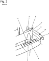
- Figure 2 shows in detail the area of the wringing device 1 in which a spring element 8 and a stamp body 9 are arranged.
- the spring element 8 is molded in one piece and made of the same material into the holder 3 and the stamp body 9 is molded into the receptacle 2.
- the stamp bodies 9 rest on the spring elements 8 without significantly deforming them.
- Figure 3 shows the in Figure 2 described area in the loaded state. If a wiper device is pressed into the receptacle 2, the latter moves in a translatory manner onto the holder 3. In the process, the stamp bodies 9 press on the spring elements 8 and deform them. In the present embodiment, the serpentine spring element 8 is deformed into an arc.
- the spring element 8 is designed in the form of a cracking frog and has a metastable state when it is fully compressed. As a result, the spring force decreases again when the compression is complete, so that the wringing device 1 is more comfortable to operate overall.
- Figure 4 shows the wringing device 1 in plan view.
- the slots 14 made in the receptacle 2 and passages through which the wrung-out cleaning liquid can run into the mopping bucket can be seen.
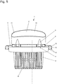
- Figure 5 shows the wringing device 1 in a front view.
- Figure 6 shows the wringing device 1 in side view.
- Figure 7 shows in detail the holder 3 and
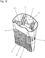
- Figure 8 shows recording 2 in detail.
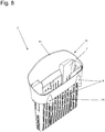
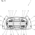
- Figures 9 and 10 show an alternative embodiment of the wringing device 1.
- the guide 5 is formed from columnar projections 6, which are made of the same material and formed in one piece from the holder 3 and from openings 15 which are made in the receptacle 2 and through which the projections 6 in the inside of the receptacle 2 protrude.
- the recesses made in the receptacle 2 are omitted, so that the clear width of the basket-like receptacle 2 is enlarged. In this way, voluminous mops can be picked up and pressed deeply into the receptacle 2.
- the projections 6 are shaped so that a mop along the projections 6 protruding through the openings 15 into the receptacle 2 can be pressed in.
- the bottom 17 of the receptacle 2 has an elevation 18. This is preferably arranged centrally in the bottom 17 of the receptacle 2, so that depressions are produced on both sides. This configuration improves the wringing performance of mops with a hemmed edge. The edge thickened by the hemming is received in the depressions and the section forming the wiping surface of the mop comes to rest on the elevation 18.
- Figure 11 shows in detail the holder 3 and Figure 12 shows recording 2 in detail.
Landscapes
- Cleaning Implements For Floors, Carpets, Furniture, Walls, And The Like (AREA)
- Drying Of Solid Materials (AREA)
Priority Applications (1)
| Application Number | Priority Date | Filing Date | Title |
|---|---|---|---|
| PL16813237T PL3393324T3 (pl) | 2015-12-21 | 2016-12-19 | Urządzenie wyżymające do mopa |
Applications Claiming Priority (3)
| Application Number | Priority Date | Filing Date | Title |
|---|---|---|---|
| DE102015016459 | 2015-12-21 | ||
| DE102016014403.3A DE102016014403A1 (de) | 2015-12-21 | 2016-12-05 | Auswringvorrichtung für ein Wischgerät |
| PCT/EP2016/081739 WO2017108687A1 (de) | 2015-12-21 | 2016-12-19 | Auswringvorrichtung für ein wischgerät |
Publications (2)
| Publication Number | Publication Date |
|---|---|
| EP3393324A1 EP3393324A1 (de) | 2018-10-31 |
| EP3393324B1 true EP3393324B1 (de) | 2021-07-21 |
Family
ID=58994028
Family Applications (1)
| Application Number | Title | Priority Date | Filing Date |
|---|---|---|---|
| EP16813237.1A Active EP3393324B1 (de) | 2015-12-21 | 2016-12-19 | Auswringvorrichtung für ein wischgerät |
Country Status (14)
| Country | Link |
|---|---|
| US (1) | US10786136B2 (pl) |
| EP (1) | EP3393324B1 (pl) |
| CN (1) | CN108430295B (pl) |
| AU (1) | AU2016375443B2 (pl) |
| BR (1) | BR112018010495B1 (pl) |
| CA (1) | CA3009312C (pl) |
| DE (1) | DE102016014403A1 (pl) |
| DK (1) | DK3393324T3 (pl) |
| ES (1) | ES2884899T3 (pl) |
| MX (1) | MX2018007576A (pl) |
| PL (1) | PL3393324T3 (pl) |
| PT (1) | PT3393324T (pl) |
| RU (1) | RU2687644C1 (pl) |
| WO (1) | WO2017108687A1 (pl) |
Families Citing this family (2)
| Publication number | Priority date | Publication date | Assignee | Title |
|---|---|---|---|---|
| US11896180B2 (en) | 2018-05-29 | 2024-02-13 | Unger Marketing International, Llc | Floor cleaning system |
| DE102020117838B4 (de) | 2020-07-07 | 2022-04-21 | Leifheit Aktiengesellschaft | Eimer mit Entfeuchtungseinsatz zum Auspressen eines Wischkopfes |
Citations (12)
| Publication number | Priority date | Publication date | Assignee | Title |
|---|---|---|---|---|
| EP0489238A2 (de) | 1990-12-03 | 1992-06-10 | FILTERWERK MANN & HUMMEL GMBH | Ansaugverteiler für eine Brennkraftmaschine |
| US5611104A (en) | 1996-05-24 | 1997-03-18 | Demars; Robert A. | Mop head wringer to be used with a bucket |
| ES1041890U (es) | 1998-12-14 | 1999-08-01 | Reales Rosa Monsalve | Dispositivo para escurrir elementos de limpieza. |
| DE29922580U1 (de) | 1999-12-22 | 2000-03-02 | Mondotrade Ag, Siebnen | Zwischenreinigungsvorrichtung für auf einem plattenförmigen Träger aufgespannten Naßwischmop |
| EP1224901A2 (de) | 2001-01-18 | 2002-07-24 | Carl Freudenberg KG | Auswringvorrichtung |
| EP1743565A1 (en) | 2004-02-27 | 2007-01-17 | Sp Berner Plastic Group, S.L. | Wringer for scrubbing buckets |
| EP2384682A2 (de) | 2010-05-05 | 2011-11-09 | Leifheit AG | Auspresskorb für den Wischbezug eines Bodenwischers und Kombination eines Auspresskorbs mit einem Behälter |
| EP2389850A1 (en) | 2010-05-28 | 2011-11-30 | SP Berner Plastic Group, S.L. | Wringer for mops and the like with device for filtering the washing water |
| DE202014005331U1 (de) | 2013-08-20 | 2014-07-17 | Carl Freudenberg Kg | Torsionswringer |
| EP2868250A1 (de) | 2013-10-31 | 2015-05-06 | Leifheit Ag | Pressaufsatz für einen Eimer eines Wischsystems und Wischsystem |
| WO2015168060A1 (en) | 2014-04-28 | 2015-11-05 | Telebrands Corp | Rotating mop handle and bucket assembly |
| CN103735234B (zh) | 2014-01-09 | 2015-12-09 | 任强 | 柱筒弹簧升降手压旋转拖把清洗甩干器 |
Family Cites Families (11)
| Publication number | Priority date | Publication date | Assignee | Title |
|---|---|---|---|---|
| US3280418A (en) * | 1963-09-05 | 1966-10-25 | Inm Ind Corp | Squeezer for mop heads |
| DE4038372A1 (de) | 1990-12-01 | 1992-06-04 | Schlerf Coronet Werke | Auswringvorrichtung fuer reinigungselemente von feuchtreinigungsgeraeten |
| US5615446A (en) * | 1995-08-07 | 1997-04-01 | Cetnarowski; Charles E. | Deck mop wringer with adjustable support stands |
| US5974621A (en) * | 1997-11-03 | 1999-11-02 | Wilen Products, Inc. | Mop wringer with mop handle support |
| US6065175A (en) * | 1998-08-13 | 2000-05-23 | Tejerina; Silvia Reyero | Flooring mopping system |
| DE10045525C1 (de) * | 2000-09-13 | 2002-02-07 | Freudenberg Carl Kg | Auswringvorrichtung |
| DE10210569B4 (de) | 2002-03-09 | 2009-09-24 | Carl Freudenberg Kg | Auswringvorrichtung für einen Flachwischer und Reinigungssystem |
| GB0505103D0 (en) * | 2005-03-14 | 2005-04-20 | 3M Innovative Properties Co | Bucket with an internal partition |
| CN104519781B (zh) * | 2012-08-08 | 2018-11-09 | E.D.奥茨公司 | 拖把桶 |
| CN203000861U (zh) | 2012-12-28 | 2013-06-19 | 陈艳波 | 一种新型拖把脱水桶 |
| DE102013112955A1 (de) * | 2013-11-22 | 2015-05-28 | Allsafe Jungfalk Gmbh & Co. Kg | Laderaumaufteilungssystem für Transportfahrzeuge, insbesondere für Kühlfahrzeuge |
-
2016
- 2016-12-05 DE DE102016014403.3A patent/DE102016014403A1/de active Pending
- 2016-12-19 WO PCT/EP2016/081739 patent/WO2017108687A1/de not_active Ceased
- 2016-12-19 PL PL16813237T patent/PL3393324T3/pl unknown
- 2016-12-19 CN CN201680075046.7A patent/CN108430295B/zh active Active
- 2016-12-19 MX MX2018007576A patent/MX2018007576A/es unknown
- 2016-12-19 CA CA3009312A patent/CA3009312C/en active Active
- 2016-12-19 RU RU2018126739A patent/RU2687644C1/ru active
- 2016-12-19 ES ES16813237T patent/ES2884899T3/es active Active
- 2016-12-19 BR BR112018010495-7A patent/BR112018010495B1/pt active IP Right Grant
- 2016-12-19 EP EP16813237.1A patent/EP3393324B1/de active Active
- 2016-12-19 AU AU2016375443A patent/AU2016375443B2/en active Active
- 2016-12-19 PT PT168132371T patent/PT3393324T/pt unknown
- 2016-12-19 US US16/063,704 patent/US10786136B2/en active Active
- 2016-12-19 DK DK16813237.1T patent/DK3393324T3/da active
Patent Citations (12)
| Publication number | Priority date | Publication date | Assignee | Title |
|---|---|---|---|---|
| EP0489238A2 (de) | 1990-12-03 | 1992-06-10 | FILTERWERK MANN & HUMMEL GMBH | Ansaugverteiler für eine Brennkraftmaschine |
| US5611104A (en) | 1996-05-24 | 1997-03-18 | Demars; Robert A. | Mop head wringer to be used with a bucket |
| ES1041890U (es) | 1998-12-14 | 1999-08-01 | Reales Rosa Monsalve | Dispositivo para escurrir elementos de limpieza. |
| DE29922580U1 (de) | 1999-12-22 | 2000-03-02 | Mondotrade Ag, Siebnen | Zwischenreinigungsvorrichtung für auf einem plattenförmigen Träger aufgespannten Naßwischmop |
| EP1224901A2 (de) | 2001-01-18 | 2002-07-24 | Carl Freudenberg KG | Auswringvorrichtung |
| EP1743565A1 (en) | 2004-02-27 | 2007-01-17 | Sp Berner Plastic Group, S.L. | Wringer for scrubbing buckets |
| EP2384682A2 (de) | 2010-05-05 | 2011-11-09 | Leifheit AG | Auspresskorb für den Wischbezug eines Bodenwischers und Kombination eines Auspresskorbs mit einem Behälter |
| EP2389850A1 (en) | 2010-05-28 | 2011-11-30 | SP Berner Plastic Group, S.L. | Wringer for mops and the like with device for filtering the washing water |
| DE202014005331U1 (de) | 2013-08-20 | 2014-07-17 | Carl Freudenberg Kg | Torsionswringer |
| EP2868250A1 (de) | 2013-10-31 | 2015-05-06 | Leifheit Ag | Pressaufsatz für einen Eimer eines Wischsystems und Wischsystem |
| CN103735234B (zh) | 2014-01-09 | 2015-12-09 | 任强 | 柱筒弹簧升降手压旋转拖把清洗甩干器 |
| WO2015168060A1 (en) | 2014-04-28 | 2015-11-05 | Telebrands Corp | Rotating mop handle and bucket assembly |
Also Published As
| Publication number | Publication date |
|---|---|
| CA3009312A1 (en) | 2017-06-29 |
| WO2017108687A1 (de) | 2017-06-29 |
| ES2884899T3 (es) | 2021-12-13 |
| BR112018010495A8 (pt) | 2019-02-26 |
| CN108430295A (zh) | 2018-08-21 |
| AU2016375443A1 (en) | 2018-07-12 |
| PL3393324T3 (pl) | 2021-12-27 |
| DK3393324T3 (da) | 2021-10-11 |
| AU2016375443B2 (en) | 2019-10-10 |
| EP3393324A1 (de) | 2018-10-31 |
| RU2687644C1 (ru) | 2019-05-15 |
| PT3393324T (pt) | 2021-08-02 |
| US20180368650A1 (en) | 2018-12-27 |
| BR112018010495A2 (pt) | 2018-11-13 |
| BR112018010495B1 (pt) | 2022-08-09 |
| US10786136B2 (en) | 2020-09-29 |
| CA3009312C (en) | 2020-02-25 |
| CN108430295B (zh) | 2021-08-03 |
| MX2018007576A (es) | 2018-09-21 |
| DE102016014403A1 (de) | 2017-06-22 |
Similar Documents
| Publication | Publication Date | Title |
|---|---|---|
| DE10050957B4 (de) | Sitzlängsverstellung | |
| DE202015105635U1 (de) | Flachwischmopp mit einem Selbstauswringsystem | |
| EP0564952B1 (de) | Kühlschranktür | |
| DE3410047A1 (de) | Permutationsschloss zum sichern von skiern, fahrraedern oder dergleichen | |
| EP0489237B1 (de) | Auswringvorrichtung für Reinigungselemente von Feuchtreinigungsgeräten | |
| EP2700337B1 (de) | Kaffeemaschine | |
| EP3393324B1 (de) | Auswringvorrichtung für ein wischgerät | |
| EP1897480B1 (de) | Wischbezug | |
| EP2868250A1 (de) | Pressaufsatz für einen Eimer eines Wischsystems und Wischsystem | |
| EP3108766B1 (de) | Armlehne, insbesondere für einen bürostuhl | |
| EP2677917A1 (de) | Wischgerät | |
| DE202010003117U1 (de) | Steckverbindervorrichtung mit einer Entriegelungsvorrichtung | |
| DE202013105155U1 (de) | Haarschneider mit einem verriegelbaren Schneidkopf | |
| EP1753337B1 (de) | Wischsystem, auswringvorrichtung und wischgerät | |
| DE102006036460A1 (de) | Siebkorb | |
| DE202006011942U1 (de) | Siebkorb | |
| EP3801170B1 (de) | Wischplatte | |
| DE102018112822A1 (de) | Wischplatte | |
| EP3254604A1 (de) | Geschirrkorb und haushalts-geschirrspülmaschine mit demselben | |
| WO2016150647A1 (de) | Wartungsklappe für ein hausgerät und hausgerät | |
| DE102019117736A1 (de) | Innenschubkasten und Möbel oder Haushaltsgerät | |
| DE102004048065A1 (de) | Teilbarer Teleskoparm für Reinigungsgeräte | |
| AT526255B1 (de) | Vorrichtung zum Fixieren eines Schubkastens | |
| EP4258954B1 (de) | Filtervorrichtung zum filtern von unlöslichem material | |
| DE102006053592A1 (de) | Gleitstab mit Rasteinheit |
Legal Events
| Date | Code | Title | Description |
|---|---|---|---|
| STAA | Information on the status of an ep patent application or granted ep patent |
Free format text: STATUS: UNKNOWN |
|
| STAA | Information on the status of an ep patent application or granted ep patent |
Free format text: STATUS: THE INTERNATIONAL PUBLICATION HAS BEEN MADE |
|
| PUAI | Public reference made under article 153(3) epc to a published international application that has entered the european phase |
Free format text: ORIGINAL CODE: 0009012 |
|
| STAA | Information on the status of an ep patent application or granted ep patent |
Free format text: STATUS: REQUEST FOR EXAMINATION WAS MADE |
|
| 17P | Request for examination filed |
Effective date: 20180612 |
|
| AK | Designated contracting states |
Kind code of ref document: A1 Designated state(s): AL AT BE BG CH CY CZ DE DK EE ES FI FR GB GR HR HU IE IS IT LI LT LU LV MC MK MT NL NO PL PT RO RS SE SI SK SM TR |
|
| AX | Request for extension of the european patent |
Extension state: BA ME |
|
| DAV | Request for validation of the european patent (deleted) | ||
| DAX | Request for extension of the european patent (deleted) | ||
| STAA | Information on the status of an ep patent application or granted ep patent |
Free format text: STATUS: EXAMINATION IS IN PROGRESS |
|
| 17Q | First examination report despatched |
Effective date: 20200511 |
|
| GRAP | Despatch of communication of intention to grant a patent |
Free format text: ORIGINAL CODE: EPIDOSNIGR1 |
|
| STAA | Information on the status of an ep patent application or granted ep patent |
Free format text: STATUS: GRANT OF PATENT IS INTENDED |
|
| INTG | Intention to grant announced |
Effective date: 20210226 |
|
| GRAS | Grant fee paid |
Free format text: ORIGINAL CODE: EPIDOSNIGR3 |
|
| GRAA | (expected) grant |
Free format text: ORIGINAL CODE: 0009210 |
|
| STAA | Information on the status of an ep patent application or granted ep patent |
Free format text: STATUS: THE PATENT HAS BEEN GRANTED |
|
| AK | Designated contracting states |
Kind code of ref document: B1 Designated state(s): AL AT BE BG CH CY CZ DE DK EE ES FI FR GB GR HR HU IE IS IT LI LT LU LV MC MK MT NL NO PL PT RO RS SE SI SK SM TR |
|
| REG | Reference to a national code |
Ref country code: GB Ref legal event code: FG4D Free format text: NOT ENGLISH |
|
| REG | Reference to a national code |
Ref country code: CH Ref legal event code: EP |
|
| REG | Reference to a national code |
Ref country code: PT Ref legal event code: SC4A Ref document number: 3393324 Country of ref document: PT Date of ref document: 20210802 Kind code of ref document: T Free format text: AVAILABILITY OF NATIONAL TRANSLATION Effective date: 20210728 |
|
| REG | Reference to a national code |
Ref country code: DE Ref legal event code: R096 Ref document number: 502016013461 Country of ref document: DE |
|
| REG | Reference to a national code |
Ref country code: AT Ref legal event code: REF Ref document number: 1411813 Country of ref document: AT Kind code of ref document: T Effective date: 20210815 |
|
| REG | Reference to a national code |
Ref country code: IE Ref legal event code: FG4D Free format text: LANGUAGE OF EP DOCUMENT: GERMAN |
|
| REG | Reference to a national code |
Ref country code: DK Ref legal event code: T3 Effective date: 20211007 |
|
| REG | Reference to a national code |
Ref country code: DE Ref legal event code: R055 Ref document number: 502016013461 Country of ref document: DE |
|
| PLCP | Request for limitation filed |
Free format text: ORIGINAL CODE: EPIDOSNLIM1 |
|
| REG | Reference to a national code |
Ref country code: SE Ref legal event code: TRGR |
|
| REG | Reference to a national code |
Ref country code: NL Ref legal event code: FP Ref country code: SK Ref legal event code: T3 Ref document number: E 38137 Country of ref document: SK |
|
| PLCQ | Request for limitation of patent found admissible |
Free format text: ORIGINAL CODE: 0009231 |
|
| REG | Reference to a national code |
Ref country code: LT Ref legal event code: MG9D |
|
| LIM1 | Request for limitation found admissible |
Free format text: SEQUENCE NO: 1; FILED DURING OPPOSITION PERIOD Filing date: 20211022 Effective date: 20211022 |
|
| REG | Reference to a national code |
Ref country code: ES Ref legal event code: FG2A Ref document number: 2884899 Country of ref document: ES Kind code of ref document: T3 Effective date: 20211213 |
|
| PG25 | Lapsed in a contracting state [announced via postgrant information from national office to epo] |
Ref country code: LT Free format text: LAPSE BECAUSE OF FAILURE TO SUBMIT A TRANSLATION OF THE DESCRIPTION OR TO PAY THE FEE WITHIN THE PRESCRIBED TIME-LIMIT Effective date: 20210721 Ref country code: BG Free format text: LAPSE BECAUSE OF FAILURE TO SUBMIT A TRANSLATION OF THE DESCRIPTION OR TO PAY THE FEE WITHIN THE PRESCRIBED TIME-LIMIT Effective date: 20211021 Ref country code: NO Free format text: LAPSE BECAUSE OF FAILURE TO SUBMIT A TRANSLATION OF THE DESCRIPTION OR TO PAY THE FEE WITHIN THE PRESCRIBED TIME-LIMIT Effective date: 20211021 Ref country code: HR Free format text: LAPSE BECAUSE OF FAILURE TO SUBMIT A TRANSLATION OF THE DESCRIPTION OR TO PAY THE FEE WITHIN THE PRESCRIBED TIME-LIMIT Effective date: 20210721 Ref country code: FI Free format text: LAPSE BECAUSE OF FAILURE TO SUBMIT A TRANSLATION OF THE DESCRIPTION OR TO PAY THE FEE WITHIN THE PRESCRIBED TIME-LIMIT Effective date: 20210721 Ref country code: RS Free format text: LAPSE BECAUSE OF FAILURE TO SUBMIT A TRANSLATION OF THE DESCRIPTION OR TO PAY THE FEE WITHIN THE PRESCRIBED TIME-LIMIT Effective date: 20210721 |
|
| PG25 | Lapsed in a contracting state [announced via postgrant information from national office to epo] |
Ref country code: LV Free format text: LAPSE BECAUSE OF FAILURE TO SUBMIT A TRANSLATION OF THE DESCRIPTION OR TO PAY THE FEE WITHIN THE PRESCRIBED TIME-LIMIT Effective date: 20210721 Ref country code: GR Free format text: LAPSE BECAUSE OF FAILURE TO SUBMIT A TRANSLATION OF THE DESCRIPTION OR TO PAY THE FEE WITHIN THE PRESCRIBED TIME-LIMIT Effective date: 20211022 |
|
| REG | Reference to a national code |
Ref country code: DE Ref legal event code: R026 Ref document number: 502016013461 Country of ref document: DE |
|
| PLBI | Opposition filed |
Free format text: ORIGINAL CODE: 0009260 |
|
| PLAX | Notice of opposition and request to file observation + time limit sent |
Free format text: ORIGINAL CODE: EPIDOSNOBS2 |
|
| 26 | Opposition filed |
Opponent name: LEIFHEIT AG Effective date: 20220420 |
|
| PG25 | Lapsed in a contracting state [announced via postgrant information from national office to epo] |
Ref country code: SM Free format text: LAPSE BECAUSE OF FAILURE TO SUBMIT A TRANSLATION OF THE DESCRIPTION OR TO PAY THE FEE WITHIN THE PRESCRIBED TIME-LIMIT Effective date: 20210721 Ref country code: RO Free format text: LAPSE BECAUSE OF FAILURE TO SUBMIT A TRANSLATION OF THE DESCRIPTION OR TO PAY THE FEE WITHIN THE PRESCRIBED TIME-LIMIT Effective date: 20210721 Ref country code: EE Free format text: LAPSE BECAUSE OF FAILURE TO SUBMIT A TRANSLATION OF THE DESCRIPTION OR TO PAY THE FEE WITHIN THE PRESCRIBED TIME-LIMIT Effective date: 20210721 Ref country code: AL Free format text: LAPSE BECAUSE OF FAILURE TO SUBMIT A TRANSLATION OF THE DESCRIPTION OR TO PAY THE FEE WITHIN THE PRESCRIBED TIME-LIMIT Effective date: 20210721 |
|
| PG25 | Lapsed in a contracting state [announced via postgrant information from national office to epo] |
Ref country code: MC Free format text: LAPSE BECAUSE OF FAILURE TO SUBMIT A TRANSLATION OF THE DESCRIPTION OR TO PAY THE FEE WITHIN THE PRESCRIBED TIME-LIMIT Effective date: 20210721 |
|
| REG | Reference to a national code |
Ref country code: CH Ref legal event code: PL |
|
| PLBB | Reply of patent proprietor to notice(s) of opposition received |
Free format text: ORIGINAL CODE: EPIDOSNOBS3 |
|
| PG25 | Lapsed in a contracting state [announced via postgrant information from national office to epo] |
Ref country code: LU Free format text: LAPSE BECAUSE OF NON-PAYMENT OF DUE FEES Effective date: 20211219 Ref country code: IE Free format text: LAPSE BECAUSE OF NON-PAYMENT OF DUE FEES Effective date: 20211219 |
|
| PG25 | Lapsed in a contracting state [announced via postgrant information from national office to epo] |
Ref country code: LI Free format text: LAPSE BECAUSE OF NON-PAYMENT OF DUE FEES Effective date: 20211231 Ref country code: CH Free format text: LAPSE BECAUSE OF NON-PAYMENT OF DUE FEES Effective date: 20211231 |
|
| REG | Reference to a national code |
Ref country code: AT Ref legal event code: MM01 Ref document number: 1411813 Country of ref document: AT Kind code of ref document: T Effective date: 20211219 |
|
| PG25 | Lapsed in a contracting state [announced via postgrant information from national office to epo] |
Ref country code: AT Free format text: LAPSE BECAUSE OF NON-PAYMENT OF DUE FEES Effective date: 20211219 |
|
| PLAN | Information deleted related to communication of a notice of opposition and request to file observations + time limit |
Free format text: ORIGINAL CODE: EPIDOSDOBS2 |
|
| PLAS | Information related to reply of patent proprietor to notice(s) of opposition deleted |
Free format text: ORIGINAL CODE: EPIDOSDOBS3 |
|
| PLAX | Notice of opposition and request to file observation + time limit sent |
Free format text: ORIGINAL CODE: EPIDOSNOBS2 |
|
| PLBB | Reply of patent proprietor to notice(s) of opposition received |
Free format text: ORIGINAL CODE: EPIDOSNOBS3 |
|
| PG25 | Lapsed in a contracting state [announced via postgrant information from national office to epo] |
Ref country code: CY Free format text: LAPSE BECAUSE OF FAILURE TO SUBMIT A TRANSLATION OF THE DESCRIPTION OR TO PAY THE FEE WITHIN THE PRESCRIBED TIME-LIMIT Effective date: 20210721 |
|
| PG25 | Lapsed in a contracting state [announced via postgrant information from national office to epo] |
Ref country code: HU Free format text: LAPSE BECAUSE OF FAILURE TO SUBMIT A TRANSLATION OF THE DESCRIPTION OR TO PAY THE FEE WITHIN THE PRESCRIBED TIME-LIMIT; INVALID AB INITIO Effective date: 20161219 |
|
| PG25 | Lapsed in a contracting state [announced via postgrant information from national office to epo] |
Ref country code: MK Free format text: LAPSE BECAUSE OF FAILURE TO SUBMIT A TRANSLATION OF THE DESCRIPTION OR TO PAY THE FEE WITHIN THE PRESCRIBED TIME-LIMIT Effective date: 20210721 |
|
| APAH | Appeal reference modified |
Free format text: ORIGINAL CODE: EPIDOSCREFNO |
|
| APBP | Date of receipt of notice of appeal recorded |
Free format text: ORIGINAL CODE: EPIDOSNNOA2O |
|
| PG25 | Lapsed in a contracting state [announced via postgrant information from national office to epo] |
Ref country code: MT Free format text: LAPSE BECAUSE OF FAILURE TO SUBMIT A TRANSLATION OF THE DESCRIPTION OR TO PAY THE FEE WITHIN THE PRESCRIBED TIME-LIMIT Effective date: 20210721 |
|
| APBQ | Date of receipt of statement of grounds of appeal recorded |
Free format text: ORIGINAL CODE: EPIDOSNNOA3O |
|
| PLAB | Opposition data, opponent's data or that of the opponent's representative modified |
Free format text: ORIGINAL CODE: 0009299OPPO |
|
| R26 | Opposition filed (corrected) |
Opponent name: LEIFHEIT AG Effective date: 20220420 |
|
| PGFP | Annual fee paid to national office [announced via postgrant information from national office to epo] |
Ref country code: PT Payment date: 20251128 Year of fee payment: 10 |
|
| PGFP | Annual fee paid to national office [announced via postgrant information from national office to epo] |
Ref country code: GB Payment date: 20251223 Year of fee payment: 10 |
|
| PGFP | Annual fee paid to national office [announced via postgrant information from national office to epo] |
Ref country code: IT Payment date: 20251218 Year of fee payment: 10 Ref country code: DK Payment date: 20251222 Year of fee payment: 10 |
|
| PGFP | Annual fee paid to national office [announced via postgrant information from national office to epo] |
Ref country code: NL Payment date: 20251222 Year of fee payment: 10 Ref country code: FR Payment date: 20251230 Year of fee payment: 10 |
|
| PGFP | Annual fee paid to national office [announced via postgrant information from national office to epo] |
Ref country code: TR Payment date: 20251201 Year of fee payment: 10 |
|
| PGFP | Annual fee paid to national office [announced via postgrant information from national office to epo] |
Ref country code: SE Payment date: 20251222 Year of fee payment: 10 |
|
| PGFP | Annual fee paid to national office [announced via postgrant information from national office to epo] |
Ref country code: CZ Payment date: 20251208 Year of fee payment: 10 |
|
| PGFP | Annual fee paid to national office [announced via postgrant information from national office to epo] |
Ref country code: PL Payment date: 20251125 Year of fee payment: 10 |
|
| PGFP | Annual fee paid to national office [announced via postgrant information from national office to epo] |
Ref country code: SK Payment date: 20251128 Year of fee payment: 10 |
|
| PGFP | Annual fee paid to national office [announced via postgrant information from national office to epo] |
Ref country code: ES Payment date: 20260122 Year of fee payment: 10 |
|
| PGFP | Annual fee paid to national office [announced via postgrant information from national office to epo] |
Ref country code: DE Payment date: 20251229 Year of fee payment: 10 |
|
| PGFP | Annual fee paid to national office [announced via postgrant information from national office to epo] |
Ref country code: BE Payment date: 20260109 Year of fee payment: 10 |