EP3393324B1 - Wringing device for a mop - Google Patents
Wringing device for a mop Download PDFInfo
- Publication number
- EP3393324B1 EP3393324B1 EP16813237.1A EP16813237A EP3393324B1 EP 3393324 B1 EP3393324 B1 EP 3393324B1 EP 16813237 A EP16813237 A EP 16813237A EP 3393324 B1 EP3393324 B1 EP 3393324B1
- Authority
- EP
- European Patent Office
- Prior art keywords
- receptacle
- holder
- mopping
- wringing
- mop
- Prior art date
- Legal status (The legal status is an assumption and is not a legal conclusion. Google has not performed a legal analysis and makes no representation as to the accuracy of the status listed.)
- Active
Links
- 238000004080 punching Methods 0.000 claims 1
- 230000000717 retained effect Effects 0.000 claims 1
- 238000003825 pressing Methods 0.000 description 10
- 239000000463 material Substances 0.000 description 9
- 238000003780 insertion Methods 0.000 description 5
- 230000037431 insertion Effects 0.000 description 5
- 238000004140 cleaning Methods 0.000 description 4
- WYTGDNHDOZPMIW-RCBQFDQVSA-N alstonine Natural products C1=CC2=C3C=CC=CC3=NC2=C2N1C[C@H]1[C@H](C)OC=C(C(=O)OC)[C@H]1C2 WYTGDNHDOZPMIW-RCBQFDQVSA-N 0.000 description 3
- 230000006835 compression Effects 0.000 description 3
- 238000007906 compression Methods 0.000 description 3
- 239000007788 liquid Substances 0.000 description 3
- 238000000034 method Methods 0.000 description 3
- 239000004743 Polypropylene Substances 0.000 description 2
- 229920001155 polypropylene Polymers 0.000 description 2
- XLYOFNOQVPJJNP-UHFFFAOYSA-N water Substances O XLYOFNOQVPJJNP-UHFFFAOYSA-N 0.000 description 2
- 238000005336 cracking Methods 0.000 description 1
- 230000007423 decrease Effects 0.000 description 1
- 238000009957 hemming Methods 0.000 description 1
- 239000004033 plastic Substances 0.000 description 1
- -1 polypropylene Polymers 0.000 description 1
- 229920002994 synthetic fiber Polymers 0.000 description 1
- 239000004758 synthetic textile Substances 0.000 description 1
- 230000000007 visual effect Effects 0.000 description 1
Images


Classifications
-
- A—HUMAN NECESSITIES
- A47—FURNITURE; DOMESTIC ARTICLES OR APPLIANCES; COFFEE MILLS; SPICE MILLS; SUCTION CLEANERS IN GENERAL
- A47L—DOMESTIC WASHING OR CLEANING; SUCTION CLEANERS IN GENERAL
- A47L13/00—Implements for cleaning floors, carpets, furniture, walls, or wall coverings
- A47L13/10—Scrubbing; Scouring; Cleaning; Polishing
- A47L13/50—Auxiliary implements
- A47L13/58—Wringers for scouring pads, mops, or the like, combined with buckets
Definitions
- the invention relates to a wringing device for a mopping device, comprising a basket-like receptacle into which the moping device can be wrenched by being pressed, and a holder for fastening the wringing device in a mopping bucket.
- Such a wringing device is for example from DE 102 10 569 A1 famous.
- the EP 2 384 682 A2 describes a wringing device according to the preamble of independent claim 1.
- Such mopping devices are suitable for mops or for flat mops in which the mop cover is attached to the flat mop in such a way that it cannot come off automatically.
- the mopping device is inserted into the receptacle, the mopping cover hanging down in a loop shape from the flat mop for wringing out.
- the receptacle has basket-like or sieve-like recesses so that the water that is pressed out of the mop cover or mop when the mopping device is pressed into the receptacle drips through the openings or recesses of the receptacle into the mop bucket.
- mop covers for flat mops which are made of synthetic textiles, have only a low compressibility.
- the low compressibility leads to a very steep increase in force at the end of the while the mop cover is being pressed into the wringing device Press path.
- the user does not receive any clear feedback regarding the compression of the mop cover, which makes it difficult to correctly dose the pressing force and to achieve the desired degree of wringing out.
- the invention is therefore based on the object of providing a wringing device for a mopping device which can be operated easily and ergonomically.
- the receptacle is guided in the holder in such a way that the receptacle is translationally movable in the insertion direction of the wiper device.
- the receptacle moves, if a mopping device is pressed into the receptacle, translationally in the direction of the floor of the mopping bucket.
- the user has to push the mopping device a larger amount into the receptacle.
- the user receives feedback as to whether the sufficient squeezing force to wring out the mop cover has already been achieved.
- the translational movement of the receptacle is preferably carried out against the force of a spring.
- the egg pressing force increases steadily when the mopping device is pressed into the receptacle.
- the resistance to pressing only increases gradually, so that the wringing out of the mop cover can be very well dosed and the user receives feedback on the extent to which the mop cover has already been wrung out sufficiently.
- a guide is provided which allows the translational movement of the receptacle.
- the guide prevents the mount from tilting or even rotating in the holder. This allows the wiper to be pressed into the receptacle in a defined manner. Furthermore, this results in a stable design of the wringing device.
- the guide can consist of columnar projections and congruent depressions or openings.
- the columnar projections are formed from the holder and the depressions are made in the receptacle. Projections and depressions are designed in such a way that the projections slide along in the depressions when pressed. As a result, only a translational movement of the receptacle relative to the holder is possible.
- the columnar projections are also formed from the holder. Openings through which the projections protrude are made in the receptacle.
- the projections take on two functions in that the projections enable a translational movement of the receptacle relative to the holder and in that the mop pressed into the receptacle is also guided. During the translational movement of the receptacle, the projections slide back and forth in the openings. At the same time, the mop rests against the projections and is guided into the interior of the receptacle.
- This configuration is particularly space-saving due to the lack of depressions, so that the clear width of the receptacle can be increased. As a result, voluminous mops can be wrung out in the wringing device and the mops can be pressed deeper into the receptacle.
- Spring elements are preferably provided which are deformed upon relative movement of the receptacle when the wiper device is pushed in. These cause the translational movement of the receptacle against the force of a spring.
- the spring elements can be provided in the receptacle or in the holder. In an advantageous embodiment, the spring elements are arranged in the holder.
- the spring elements can be made of the same material and in one piece from the holder.
- the spring elements can be provided in the holder in a particularly cost-effective manner. Furthermore, the assembly effort for assembling the wringing device is reduced.
- the spring elements can be assigned stamp bodies which deform the spring body when the receptacle is moved.
- the stamps are preferably designed in such a way that they come to rest against the spring elements as soon as a wiper device is pressed into the receptacle.
- the stamps cause a defined deformation so that clear feedback on the amount of press-in is possible for the user.
- the stamp bodies are assigned either to the receptacle or to the holder.
- visual display means can be provided.
- the holder is provided with a pointer which is assigned to a scale attached to the receptacle. While the mop cover is being pressed in, that is, when the receptacle is moving relative to the holder, the scale slides past the pointer.
- the scale can be provided with markings which, depending on the level of soiling and the type of floor to be cleaned, indicate when the optimum pressing force has been reached. For example, the mop cover for cleaning parquet should be loaded with a smaller amount of liquid, while the amount of liquid used for cleaning of tiles can be larger. Accordingly, a first marking can indicate when the optimum pressing force for tile cleaning is present.
- a second marking can indicate when the optimal pressing force for laminate is present.
- a third marking can indicate when the optimum pressing force for parquet is available. When the third marking is reached, the spring element is almost completely deformed and the receptacle is almost completely moved in the direction of the holder. Correspondingly, maximum wringing out of the mop cover takes place in this position.
- the holder can be held captive in the holder by means of snap hooks.
- the snap hooks are designed in such a way that a translational movement of the receptacle relative to the holder is always possible.
- the snap hooks prevent the receptacle from being completely detached from the holder; the receptacle is thus held captive on the holder by the snap hooks.
- the opening can be assigned a funnel-shaped edge that is higher on one side.
- the higher edge is preferably assigned to the side that faces away from the direction of insertion of the mopping device. This simplifies and improves the insertion of the mopping device and the funnel function of the receptacle.
- a shelf can be assigned to the wringing device.
- the shelf can either be molded into the holder or into the receptacle.
- a simple embodiment of the shelf is formed from a semicircular recess which is molded into the holder or into the receptacle.
- the shelf is used for the temporary fixation of mopping devices.
- the shelf is preferably arranged in such a way that the mopping device can be placed in the mopping bucket and is held there. The filing allows a Safe positioning of the mopping device when it is placed in the mopping bucket.
- the figures show a wringing device 1 for a mopping device.
- the wringing device 1 is designed in such a way that it is preferably suitable for mopping devices in the form of a flat mop with a foldable mopping plate on which a mop cover can be wrung out in the wringing device 1 while hanging down in a loop.
- the wringing device 1 has a basket-like receptacle 2 in which the mopping device can be wringed out by being pressed in.
- the mopping device is inserted into the receptacle 2 for wringing out.
- the mop cover of the mopping device is wrung out by compression and excess water runs through the slots 14 made in the receptacle 2 or other openings from the receptacle 2 into the mop bucket.
- the opening 10 of the receptacle 2 has a rectangular cross section.
- the opening 10 of the receptacle 2 is equipped with a funnel-shaped edge 11 for easier insertion of the mopping device.
- the edge 11 along a longitudinal edge is formed higher on one side.
- the higher section of the edge 11 is assigned to the edge of the mopping bucket and the lower section of the edge 11 is assigned to the center of the mopping bucket.
- the receptacle 2 is assigned to a holder 3, which is equipped for fastening the wringing device 1 in a mop bucket.
- the holder 3 has, at least in sections, a fixing section 13 in the edge area, which in the present embodiment is designed as a bent edge.
- the fixing section 13 is provided with snap locks 16, so that the wringing device 1 can be securely attached to the mop bucket.
- the receptacle 2 is guided in the holder 3 in such a way that the receptacle 2 is translationally movable in the insertion direction of the wiper device.
- a guide 5 is provided which only allows a translational movement of the receptacle 2 relative to the holder 3.
- the guide 5 in the configuration according to FIG Figures 1 to 8 consists of column-like projections 6 and depressions 7 that are congruent to the projections 6.
- the projections 6 are made of the same material and are formed in one piece from the holder 3.
- the recesses 7 are molded into the receptacle 2 of the same material and in one piece.
- the guide 5 in the configuration according to FIG Figures 9 to 12 is formed from columnar projections 6, which are formed from the holder 3 with the same material and in one piece, and from perforations 15 which are made in the receptacle 2 and through which the projections 6 protrude into the interior of the receptacle 2.
- the receptacle 2 remains at a distance from the base of the holder 3 in a first position. During the wringing out, the receptacle 2 moves in the direction of the holder 3 until the receptacle 2 finally comes to rest against stops or the like on the holder 3 in a second position. It is particularly conceivable here that the projections 6 come to rest on the front side against the delimitation of the depressions 7. Overall, the receptacle 2 moves in the direction of the mop bucket during wringing out, while the holder 3 does not change its position relative to the mop bucket.
- the wiper device is pressed into the receptacle 2 against the force of a spring 4.
- spring elements 8 are provided which are deformed when the wiper device is pushed in when the receptacle 2 moves relative to one another.
- the spring elements 8 are made of the same material and are formed in one piece from the holder 3.
- the receptacle 2 openings are made, in which serpentine spring elements 8 are provided.
- the spring elements 8, which are molded into the holder 3, are assigned stamp bodies 9 which deform the spring elements 8 when the receptacle 2 is moved.
- the stamp bodies 9 are made of the same material and are made in one piece from the receptacle 2. During the wringing out, the stamp bodies 9 come to rest on the serpentine spring elements 8, the spring elements 8 being designed in such a way that a central elevation of a spring element 8 interacts with a stamp body 9. In the process, the spring element 8 is deformed and the resulting spring force counteracts the pressing in of the wiper device.
- the spring force counteracting the pressing in of the mopping device increases steadily and gradually and the user receives feedback on the wringing-out process.
- a display device can be provided.
- the display device signals the amount by which the receptacle 2 has shifted relative to the holder 3.
- a pointer can be arranged on the holder 3 and a scale can be arranged on the receptacle 2, or vice versa.
- the receptacle 2 is held captive in the holder 3 via snap hooks 12.
- the receptacle 2 can move translationally to the holder 3 within predetermined limits.
- the holder 3 is assigned a shelf which is formed from the holder 3 in a single material and in one piece.
- the shelf consists of a semicircular recess which is made in the holder 3.
- the receptacle 2 and the holder 3 are made of injection-moldable plastic, in this embodiment made of polypropylene (PP).
- Figure 1 shows the wringing device 1 in a spatial representation.
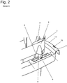
- Figure 2 shows in detail the area of the wringing device 1 in which a spring element 8 and a stamp body 9 are arranged.
- the spring element 8 is molded in one piece and made of the same material into the holder 3 and the stamp body 9 is molded into the receptacle 2.
- the stamp bodies 9 rest on the spring elements 8 without significantly deforming them.
- Figure 3 shows the in Figure 2 described area in the loaded state. If a wiper device is pressed into the receptacle 2, the latter moves in a translatory manner onto the holder 3. In the process, the stamp bodies 9 press on the spring elements 8 and deform them. In the present embodiment, the serpentine spring element 8 is deformed into an arc.
- the spring element 8 is designed in the form of a cracking frog and has a metastable state when it is fully compressed. As a result, the spring force decreases again when the compression is complete, so that the wringing device 1 is more comfortable to operate overall.
- Figure 4 shows the wringing device 1 in plan view.
- the slots 14 made in the receptacle 2 and passages through which the wrung-out cleaning liquid can run into the mopping bucket can be seen.
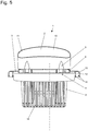
- Figure 5 shows the wringing device 1 in a front view.
- Figure 6 shows the wringing device 1 in side view.
- Figure 7 shows in detail the holder 3 and
- Figure 8 shows recording 2 in detail.
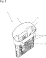
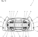
- Figures 9 and 10 show an alternative embodiment of the wringing device 1.
- the guide 5 is formed from columnar projections 6, which are made of the same material and formed in one piece from the holder 3 and from openings 15 which are made in the receptacle 2 and through which the projections 6 in the inside of the receptacle 2 protrude.
- the recesses made in the receptacle 2 are omitted, so that the clear width of the basket-like receptacle 2 is enlarged. In this way, voluminous mops can be picked up and pressed deeply into the receptacle 2.
- the projections 6 are shaped so that a mop along the projections 6 protruding through the openings 15 into the receptacle 2 can be pressed in.
- the bottom 17 of the receptacle 2 has an elevation 18. This is preferably arranged centrally in the bottom 17 of the receptacle 2, so that depressions are produced on both sides. This configuration improves the wringing performance of mops with a hemmed edge. The edge thickened by the hemming is received in the depressions and the section forming the wiping surface of the mop comes to rest on the elevation 18.
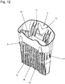
- Figure 11 shows in detail the holder 3 and Figure 12 shows recording 2 in detail.
Description
Die Erfindung betrifft eine Auswringvorrichtung für ein Wischgerät, umfassend eine korbartige Aufnahme, in welche das Wischgerät durch Eindrücken auswringbar ist und eine Halterung zur Befestigung zur Auswringvorrichtung in einen Wischeimer.The invention relates to a wringing device for a mopping device, comprising a basket-like receptacle into which the moping device can be wrenched by being pressed, and a holder for fastening the wringing device in a mopping bucket.
Eine derartige Auswringvorrichtung ist beispielsweise aus der
Die Aufnahme weist korb- oder siebartige Ausnehmungen auf, so dass das Wasser, welches beim Eindrücken des Wischgerätes in die Aufnahme aus dem Wischbezug beziehungsweise aus dem Wischmopp ausgepresst wird, durch die Durchbrechungen oder Ausnehmungen der Aufnahme hindurch in den Wischeimer tropft.The receptacle has basket-like or sieve-like recesses so that the water that is pressed out of the mop cover or mop when the mopping device is pressed into the receptacle drips through the openings or recesses of the receptacle into the mop bucket.
Insbesondere Wischbezüge für Flachwischer, welche aus synthetischen Textilien bestehen weisen nur eine geringe Kompressibilität auf. Die niedrige Kompressibilität führt während des Eindrückens des Wischbezugs in die Auswringvorrichtung zu einem sehr steilen Kraftanstieg am Ende des Pressweges. Dadurch erhält der Benutzer keine klare Rückmeldung hinsichtlich der Kompression des Wischbezugs, was die richtige Dosierung der Presskraft und das Erreichen eines gewünschten Auswringgrades erschwert.In particular, mop covers for flat mops, which are made of synthetic textiles, have only a low compressibility. The low compressibility leads to a very steep increase in force at the end of the while the mop cover is being pressed into the wringing device Press path. As a result, the user does not receive any clear feedback regarding the compression of the mop cover, which makes it difficult to correctly dose the pressing force and to achieve the desired degree of wringing out.
Somit liegt der Erfindung die Aufgabe zugrunde, eine Auswringvorrichtung für ein Wischgerät bereitzustellen, welche einfach und ergonomisch bedienbar ist.The invention is therefore based on the object of providing a wringing device for a mopping device which can be operated easily and ergonomically.
Diese Aufgabe wird mit den Merkmalen von Anspruch 1 gelöst. Auf vorteilhafte Ausgestaltungen nehmen die Unteransprüche Bezug.This object is achieved with the features of
Zur Lösung der Aufgabe ist die Aufnahme in der Halterung derart geführt, dass die Aufnahme in Einführrichtung des Wischgeräts translatorisch beweglich ist. Dadurch bewegt sich die Aufnahme, wird ein Wischgerät in die Aufnahme eingedrückt, translatorisch in Richtung des Wischeimerbodens. Das bedeutet, dass der Benutzer zum Auswringen eines Wischbezugs das Wischgerät um ein größeres Maß in die Aufnahme hineindrücken muss. Dadurch erhält der Benutzer auch bei nur gering komprimierbaren Wischbezügen eine Rückmeldung darüber, ob die ausreichende Auspresskraft zum Auswringen des Wischbezugs bereits erreicht wurde.To achieve the object, the receptacle is guided in the holder in such a way that the receptacle is translationally movable in the insertion direction of the wiper device. As a result, the receptacle moves, if a mopping device is pressed into the receptacle, translationally in the direction of the floor of the mopping bucket. This means that in order to wring out a mop cover, the user has to push the mopping device a larger amount into the receptacle. As a result, even with mop covers that are only slightly compressible, the user receives feedback as to whether the sufficient squeezing force to wring out the mop cover has already been achieved.
Vorzugsweise erfolgt die translatorische Bewegung der Aufnahme gegen die Kraft einer Feder. Dadurch steigt die Eipresskraft stetig an, wenn das Wischgerät in die Aufnahme eingedrückt wird. Anders als bei komprimierbaren Wischbezügen die in eine starre Aufnahme eingedrückt werden steigt der Widerstand gegen das Eindrücken nur allmählich an, sodass das Auswringen des Wischbezugs sehr gut dosiert werden kann und der Benutzer eine Rückmeldung darüber erhält, inwieweit der Wischbezug bereits ausreichend ausgewrungen ist.The translational movement of the receptacle is preferably carried out against the force of a spring. As a result, the egg pressing force increases steadily when the mopping device is pressed into the receptacle. In contrast to compressible mop covers that are pressed into a rigid receptacle, the resistance to pressing only increases gradually, so that the wringing out of the mop cover can be very well dosed and the user receives feedback on the extent to which the mop cover has already been wrung out sufficiently.
Vorzugsweise ist eine Führung vorgesehen, welche die translatorische Bewegung der Aufnahme zulässt. Die Führung verhindert, dass die Aufnahme in der Halterung kippelt oder gar drehbeweglich ist. Dadurch kann das Wischgerät definiert in die Aufnahme eingedrückt werden. Des Weiteren ergibt sich dadurch eine stabile Ausgestaltung der Auswringvorrichtung.Preferably, a guide is provided which allows the translational movement of the receptacle. The guide prevents the mount from tilting or even rotating in the holder. This allows the wiper to be pressed into the receptacle in a defined manner. Furthermore, this results in a stable design of the wringing device.
Die Führung kann aus säulenartigen Vorsprüngen und kongruenten Vertiefungen oder Durchbrechungen bestehen. Nach einer ersten Ausgestaltung sind die säulenartigen Vorsprünge aus der Halterung ausgebildet und die Vertiefungen sind in die Aufnahme eingebracht. Dabei sind Vorsprünge und Vertiefungen so ausgebildet, dass die Vorsprünge beim Eindrücken in den Vertiefungen entlanggleiten. Dadurch ist lediglich eine translatorische Bewegung der Aufnahme relativ zu der Halterung möglich.The guide can consist of columnar projections and congruent depressions or openings. According to a first embodiment, the columnar projections are formed from the holder and the depressions are made in the receptacle. Projections and depressions are designed in such a way that the projections slide along in the depressions when pressed. As a result, only a translational movement of the receptacle relative to the holder is possible.
Nach einer alternativen Ausgestaltung sind die säulenartigen Vorsprünge ebenfalls aus der Halterung ausgebildet. In die Aufnahme sind Durchbrechungen eingebracht, durch welche die Vorsprünge hindurchragen. Bei dieser Ausgestaltung übernehmen die Vorsprünge zwei Funktionen indem die Vorsprünge eine translatorische Bewegung der Aufnahme relativ zu der Halterung ermöglicht und indem der in die Aufnahme eingedrückte Wischmopp ebenfalls geführt wird. Während der translatorischen Bewegung der Aufnahme gleiten die Vorsprünge in den Durchbrechungen hin und her. Gleichzeitig liegt der Wischmopp an den Vorsprüngen an und wird in das Innere der Aufnahme geführt. Diese Ausgestaltung ist aufgrund der fehlenden Vertiefungen besonders Platz sparend, so dass die lichte Weite der Aufnahme vergrößert werden kann. Dadurch können voluminöse Wischmops in der Auswringvorrichtung ausgewrungen werden und die Wischmopps können tiefer in die Aufnahme gedrückt werden.According to an alternative embodiment, the columnar projections are also formed from the holder. Openings through which the projections protrude are made in the receptacle. In this embodiment, the projections take on two functions in that the projections enable a translational movement of the receptacle relative to the holder and in that the mop pressed into the receptacle is also guided. During the translational movement of the receptacle, the projections slide back and forth in the openings. At the same time, the mop rests against the projections and is guided into the interior of the receptacle. This configuration is particularly space-saving due to the lack of depressions, so that the clear width of the receptacle can be increased. As a result, voluminous mops can be wrung out in the wringing device and the mops can be pressed deeper into the receptacle.
Vorzugsweise sind Federelemente vorgesehen, welche bei Relativbewegung der Aufnahme bei Eindrücken des Wischgerätes verformt werden. Diese bewirken die translatorische Bewegung der Aufnahme gegen die Kraft einer Feder. Dabei können die Federelemente in der Aufnahme oder in der Halterung vorgesehen sein. In einer vorteilhaften Ausgestaltung sind die Federelemente in der Halterung angeordnet.Spring elements are preferably provided which are deformed upon relative movement of the receptacle when the wiper device is pushed in. These cause the translational movement of the receptacle against the force of a spring. The spring elements can be provided in the receptacle or in the holder. In an advantageous embodiment, the spring elements are arranged in the holder.
Dabei können die Federelemente materialeinheitlich und einstückig aus der Halterung ausgebildet sein. Dadurch können die Federelemente besonders kostengünstig in der Halterung vorgesehen werden. Des Weiteren sinkt der Montageaufwand zur Montage der Auswringvorrichtung.In this case, the spring elements can be made of the same material and in one piece from the holder. As a result, the spring elements can be provided in the holder in a particularly cost-effective manner. Furthermore, the assembly effort for assembling the wringing device is reduced.
Den Federelementen können Stempelkörper zugeordnet sein, welche bei Bewegung der Aufnahme die Federkörper verformen. Die Stempel sind vorzugsweise so ausgebildet, dass diese zur Anlage an die Federelemente gelangen, sobald ein Wischgerät in die Aufnahme eingedrückt wird. Die Stempel bewirken ein definiertes Verformen, sodass eine eindeutige Rückmeldung über das Maß der Einpressung an den Benutzer möglich ist. Je nach Anordnung der Federelemente sind die Stempelkörper entweder der Aufnahme oder der Halterung zugeordnet.The spring elements can be assigned stamp bodies which deform the spring body when the receptacle is moved. The stamps are preferably designed in such a way that they come to rest against the spring elements as soon as a wiper device is pressed into the receptacle. The stamps cause a defined deformation so that clear feedback on the amount of press-in is possible for the user. Depending on the arrangement of the spring elements, the stamp bodies are assigned either to the receptacle or to the holder.
Zusätzlich können visuelle Anzeigemittel vorgesehen sein. Dazu ist es denkbar, dass dem Halter ein Zeiger vorgesehen ist, welcher einer an der Aufnahme angebrachten Skala zugeordnet ist. Während des Eindrückens des Wischbezuges, also wenn sich die Aufnahme relativ zu der Halterung bewegt, gleitet die Skala an dem Zeiger vorbei. Dabei kann die Skala mit Markierungen versehen sein, welche je nach Verschmutzung und Art des zu reinigenden Bodens signalisieren, wenn die optimale Presskraft erreicht ist. Beispielsweise soll der Wischbezug für die Reinigung von Parkett mit einer geringeren Flüssigkeitsmenge beladen sein, während die Flüssigkeitsmenge zur Reinigung von Fliesen größer sein kann. Dementsprechend kann eine erste Markierung anzeigen, wenn die optimale Presskraft für Fliesenreinigung vorliegt. Eine zweite Markierung kann anzeigen, wenn die optimale Presskraft für Laminat vorliegt. Eine dritte Markierung kann anzeigen, wenn die optimale Presskraft für Parkett vorliegt. Bei Erreichen der dritten Markierung ist das Federelement nahezu vollständig verformt und die Aufnahme ist nahezu vollständig in Richtung der Halterung verfahren. Dementsprechend erfolgt in dieser Position ein maximales Auswringen des Wischbezugs.In addition, visual display means can be provided. For this purpose, it is conceivable that the holder is provided with a pointer which is assigned to a scale attached to the receptacle. While the mop cover is being pressed in, that is, when the receptacle is moving relative to the holder, the scale slides past the pointer. The scale can be provided with markings which, depending on the level of soiling and the type of floor to be cleaned, indicate when the optimum pressing force has been reached. For example, the mop cover for cleaning parquet should be loaded with a smaller amount of liquid, while the amount of liquid used for cleaning of tiles can be larger. Accordingly, a first marking can indicate when the optimum pressing force for tile cleaning is present. A second marking can indicate when the optimal pressing force for laminate is present. A third marking can indicate when the optimum pressing force for parquet is available. When the third marking is reached, the spring element is almost completely deformed and the receptacle is almost completely moved in the direction of the holder. Correspondingly, maximum wringing out of the mop cover takes place in this position.
Die Halterung kann über Schnapphaken verliersicher in der Halterung gehalten sein. Dabei sind die Schnapphaken so ausgebildet, dass stets eine translatorische Bewegung der Aufnahme relativ zu der Halterung möglich ist. Die Schnapphaken verhindern jedoch, dass sich die Aufnahme vollständig von der Halterung löst, die Aufnahme ist somit durch die Schnapphaken verliersicher an der Halterung gehalten.The holder can be held captive in the holder by means of snap hooks. The snap hooks are designed in such a way that a translational movement of the receptacle relative to the holder is always possible. However, the snap hooks prevent the receptacle from being completely detached from the holder; the receptacle is thus held captive on the holder by the snap hooks.
Der Öffnung kann ein trichterförmiger Rand zugeordnet sein, der einseitig höher ist. Dabei ist der höhere Rand vorzugsweise der Seite zugeordnet, die der Einführrichtung des Wischgerätes abgewandt ist. Dadurch vereinfacht und verbessert sich das Einführen des Wischgerätes und die Trichterfunktion der Aufnahme.The opening can be assigned a funnel-shaped edge that is higher on one side. The higher edge is preferably assigned to the side that faces away from the direction of insertion of the mopping device. This simplifies and improves the insertion of the mopping device and the funnel function of the receptacle.
Der Auswringvorrichtung kann eine Ablage zugeordnet sein. Dabei kann die Ablage entweder in die Halterung oder in die Aufnahme eingeformt sein. Eine einfache Ausgestaltung der Ablage ist aus einer halbkreisförmigen Vertiefung gebildet, die in die Halterung oder in die Aufnahme eingeformt ist. Die Ablage dient der vorrübergehenden Fixierung von Wischgeräten. Dabei ist die Ablage vorzugsweise derart angeordnet, dass das Wischgerät in dem Wischeimer plaziert werden kann und dort gehalten ist. Die Ablage ermöglicht insofern ein kippsicheres Positionieren des Wischgerätes, wenn diese in dem Wischeimer abgestellt wird.A shelf can be assigned to the wringing device. The shelf can either be molded into the holder or into the receptacle. A simple embodiment of the shelf is formed from a semicircular recess which is molded into the holder or into the receptacle. The shelf is used for the temporary fixation of mopping devices. The shelf is preferably arranged in such a way that the mopping device can be placed in the mopping bucket and is held there. The filing allows a Safe positioning of the mopping device when it is placed in the mopping bucket.
Einige Ausgestaltungen der erfindungsgemäßen Auswringvorrichtung werden nachfolgend anhand der Figuren näher erläutert. Diese zeigen, jeweils schematisch:
- Fig. 1
- die Auswringvorrichtung in räumlicher Darstellung;
- Fig. 2
- im Detail die Federanordnung zwischen Halterung und Aufnahme;
- Fig. 3
- im Detail die Federanordnung in eingefedertem Zustand;
- Fig. 4
- die Auswringvorrichtung in der Draufsicht;
- Fig. 5
- die Auswringvorrichtung in der Vorderansicht;
- Fig. 6
- die Auswringvorrichtung in der Seitenansicht;
- Fig. 7
- im Detail die Halterung in räumlicher Darstellung;
- Fig. 8
- im Detail die Aufnahme in räumlicher Darstellung;
- Fig. 9
- eine alternative Ausgestaltung der Auswringvorrichtung in der Vorderansicht;
- Fig. 10
- die
Auswringvorrichtung gemäß Figur 9 in der Draufsicht; - Fig. 11
- im Detail die Halterung der Auswringvorrichtung gemäß
Figur 9 in räumlicher Darstellung; - Fig. 12
- im Detail die Aufnahme der Auswringvorrichtung gemäß
Figur 9 in räumlicher Darstellung.
- Fig. 1
- the wringer in a spatial representation;
- Fig. 2
- in detail the spring arrangement between the holder and the receptacle;
- Fig. 3
- in detail the spring arrangement in the compressed state;
- Fig. 4
- the wringing device in plan view;
- Fig. 5
- the wringing device in the front view;
- Fig. 6
- the wringing device in side view;
- Fig. 7
- in detail the bracket in three-dimensional representation;
- Fig. 8
- in detail the recording in three-dimensional representation;
- Fig. 9
- an alternative embodiment of the wringing device in the front view;
- Fig. 10
- the wringer according to
Figure 9 in plan view; - Fig. 11
- in detail the holder of the wringing device according to
Figure 9 in spatial representation; - Fig. 12
- in detail the inclusion of the wringing device according to
Figure 9 in spatial representation.
Die Figuren zeigen eine Auswringvorrichtung 1 für ein Wischgerät. Dabei ist die Auswringvorrichtung 1 so ausgebildet, dass diese vorzugsweise für Wischgeräte in Form eines Flachwischers mit einer klappbaren Wischplatte geeignet ist, an welchem ein Wischbezug von der Wischplatte schlaufenartig herab hängend in der Auswringvorrichtung 1 ausgewrungen werden kann.The figures show a wringing
Die Auswringvorrichtung 1 hat eine korbartige Aufnahme 2, in welcher das Wischgerät durch Eindrücken auswringbar ist. Zum Auswringen wird das Wischgerät in die Aufnahme 2 eingeführt. Durch Eindrücken in die Aufnahme 2 wird der Wischbezug des Wischgerätes durch Kompression ausgewrungen und überschüssiges Wasser läuft durch die in die Aufnahme 2 eingebrachte Schlitze 14 oder sonstige Durchbrechungen von der Aufnahme 2 in den Wischeimer. In der vorliegenden Ausgestaltung weist die Öffnung 10 der Aufnahme 2 einen rechteckigen Querschnitt auf.The wringing
Die Öffnung 10 der Aufnahme 2 ist zum einfacheren Einführen des Wischgerätes mit einem trichterförmigen Rand 11 ausgerüstet. Der Rand 11 entlang einer Längskante ist dabei einseitig höher ausgebildet. Der höher ausgebildete Abschnitt des Randes 11 ist dem Rand des Wischeimers zugeordnet und der niedriger ausgebildete Abschnitt des Randes 11 ist der Mitte des Wischeimers zugeordnet. Dadurch kann der Wischbezug besonders sicher und einfach in die Aufnahme 2 eingeführt werden.The
Die Aufnahme 2 ist einer Halterung 3 zugeordnet, welche zur Befestigung der Auswringvorrichtung 1 in einem Wischeimer ausgerüstet ist. Dazu weist die Halterung 3 im Randbereich zumindest abschnittsweise einen Fixierabschnitt 13 auf, der in der vorliegenden Ausgestaltung als umgebogener Rand ausgestaltet ist. Ferner ist der Fixierabschnitt 13 mit Schnappverschlüssen 16 versehen, so dass die Auswringvorrichtung 1 verliersicher an dem Wischeimer befestigt werden kann.The
Die Aufnahme 2 ist in der Halterung 3 derart geführt, dass die Aufnahme 2 in Einführrichtung des Wischgeräts translatorisch beweglich ist. Dazu ist eine Führung 5 vorgesehen, welche ausschließlich eine translatorische Bewegung der Aufnahme 2 relativ zu der Halterung 3 zulässt.The
Die Führung 5 bei der Ausgestaltung gemäß der
Die Führung 5 bei der Ausgestaltung gemäß der
Unbelastet verharrt die Aufnahme 2 beabstandet zu der Basis der Halterung 3 in einer ersten Position. Während des Auswringens bewegt sich die Aufnahme 2 in Richtung auf die Halterung 3 bis die Aufnahme 2 schließlich in einer zweiten Position an Anschlägen oder dergleichen an der Halterung 3 zur Anlage gelangt. Hierbei ist insbesondere denkbar, dass die Vorsprünge 6 stirnseitig an der Begrenzung der Vertiefungen 7 zur Anlage gelangen. Insgesamt bewegt sich die Aufnahme 2 während des Auswringens in Richtung auf den Wischeimer während die Halterung 3 die Lage relativ zu dem Wischeimer nicht verändert.Unloaded, the
Das Eindrücken des Wischgerätes in die Aufnahme 2 erfolgt gegen die Kraft einer Feder 4. Dazu sind Federelemente 8 vorgesehen, welche bei Relativbewegung der Aufnahme 2 bei Eindrücken des Wischgeräts verformt werden. Die Federelemente 8 sind materialeinheitlich und einstückig aus der Halterung 3 ausgebildet sind. Dazu sind die Aufnahme 2 Durchbrechungen eingebracht, in welchen schlangenförmige Federelemente 8 vorgesehen sind.The wiper device is pressed into the
Den Federelementen 8, welche in der Halterung 3 eingeformt sind, sind Stempelkörper 9 zugeordnet, welche bei Bewegung der Aufnahme 2 die Federelemente 8 verformen. Die Stempelkörper 9 sind materialeinheitlich und einstückig aus der Aufnahme 2 ausgebildet. Während des Auswringens gelangen die Stempelkörper 9 an den schlangenförmigen Federelementen 8 zur Anlage, wobei die Federelemente 8 so ausgebildet sind, dass eine zentrale Erhebung eines Federelementes 8 mit einem Stempelkörper 9 zusammen wirkt. Dabei wird das Federelement 8 verformt und die dadurch entstandene Federkraft wirkt dem Einpressen des Wischgerätes entgegen.The
Aufgrund der Federkonstante der Federelemente 8 steigt die dem Einpressen des Wischgerätes entgegenwirkende Federkraft stetig und allmählich an und der Benutzer erhält eine Rückmeldung über den Auswringvorgang.Due to the spring constant of the
Zusätzlich kann eine Anzeigevorrichtung vorgesehen sein. Die Anzeigevorrichtung signalisiert das Maß, um welches sich die Aufnahme 2 relativ zu der Halterung 3 verschoben hat. Dazu kann an der Halterung 3 ein Zeiger und an der Aufnahme 2 eine Skala angeordnet sein oder umgekehrt.In addition, a display device can be provided. The display device signals the amount by which the
Die Aufnahme 2 ist über Schnapphaken 12 verliersicher in der Halterung 3 gehalten ist. Dabei kann sich die Aufnahme 2 in vorgegebenen Grenzen translatorisch zu der Halterung 3 bewegen. Die Schnapphaken 12 verhindern jedoch, dass sich die Aufnahme 2 unbeabsichtigt der Halterung 3 löst.The
Der Halterung 3 ist eine Ablage zugeordnet, welche materialeinheitlich und einstückig aus der Halterung 3 ausgeformt ist. In einer vorteilhaften Ausgestaltung besteht die Ablage aus einer halbkreisförmigen Vertiefung, welche in die Halterung 3 eingebracht ist. Dadurch kann das Wischgerät in dem Wischeimer abgestellt werden und ist durch die Ablage kippsicher gehalten.The
Die Aufnahme 2 und die Halterung 3 bestehen aus spritzgießfähigem Kunststoff, in dieser Ausgestaltung aus Polypropylen (PP).The
Der Boden 17 der Aufnahme 2 weist eine Erhebung 18 auf. Diese ist vorzugsweise zentral im Boden 17 der Aufnahme 2 angeordnet, so dass sich beidseitig Vertiefungen ergeben. Durch diese Ausgestaltung verbessert sich die Auswringleistung von Wischmopps mit umsäumtem Rand. Der durch das Umsäumen verdickte Rand wird in den Vertiefungen aufgenommen und der die Wischfläche des Wischmopps bildende Abschnitt gelangt auf der Erhebung 18 zur Anlage.The bottom 17 of the
Claims (9)
- Wringer (1) for a mopping appliance, comprising a basket-like receptacle (2), in which the mopping appliance can be wrung out by being pushed in, and also comprising a holder (3) for fastening the wringer (1) in a bucket, characterized in that the receptacle (2) is guided in the holder (3) such that the receptacle (2) is movable in a translatory manner in the direction of introduction of the mopping appliance, wherein a guide (5) is provided, and said guide allows the translatory movement of the receptacle (2) relative to the holder (3).
- Wringer according to Claim 1, characterized in that the movement of the receptacle (2) takes place counter to the force of a spring (4).
- Wringer according to Claim 1 or 2, characterized in that the guide (5) comprises column-like protrusions (6) and depressions (7) or apertures (15), which are congruent with the protrusions (6).
- Wringer according to one of Claims 1 to 3, characterized by the provision of spring elements (8) which are deformed during the relative movement of the receptacle (2) when the mopping appliance is being pushed in.
- Wringer according to Claim 4, characterized in that the spring elements (8) are formed from the holder (3).
- Wringer according to Claim 4 or 5, characterized in that the spring elements (8) are assigned punching members (9), which deform the spring elements (8) during movement of the receptacle (2).
- Wringer according to one of Claims 1 to 6, characterized in that the receptacle (2) is retained in the holder (3) in captive fashion via snap-fit hooks (12).
- Wringer according to one of Claims 1 to 7, characterized in that the opening (10) of the receptacle (2) is assigned a funnel-like rim (11), which is higher on one side.
- Wringer according to one of Claims 1 to 8, characterized in that a rest is provided.
Priority Applications (1)
| Application Number | Priority Date | Filing Date | Title |
|---|---|---|---|
| PL16813237T PL3393324T3 (en) | 2015-12-21 | 2016-12-19 | Wringing device for a mop |
Applications Claiming Priority (3)
| Application Number | Priority Date | Filing Date | Title |
|---|---|---|---|
| DE102015016459 | 2015-12-21 | ||
| DE102016014403.3A DE102016014403A1 (en) | 2015-12-21 | 2016-12-05 | Wringer for a wiper |
| PCT/EP2016/081739 WO2017108687A1 (en) | 2015-12-21 | 2016-12-19 | Wringing device for a mop |
Publications (2)
| Publication Number | Publication Date |
|---|---|
| EP3393324A1 EP3393324A1 (en) | 2018-10-31 |
| EP3393324B1 true EP3393324B1 (en) | 2021-07-21 |
Family
ID=58994028
Family Applications (1)
| Application Number | Title | Priority Date | Filing Date |
|---|---|---|---|
| EP16813237.1A Active EP3393324B1 (en) | 2015-12-21 | 2016-12-19 | Wringing device for a mop |
Country Status (14)
| Country | Link |
|---|---|
| US (1) | US10786136B2 (en) |
| EP (1) | EP3393324B1 (en) |
| CN (1) | CN108430295B (en) |
| AU (1) | AU2016375443B2 (en) |
| BR (1) | BR112018010495B1 (en) |
| CA (1) | CA3009312C (en) |
| DE (1) | DE102016014403A1 (en) |
| DK (1) | DK3393324T3 (en) |
| ES (1) | ES2884899T3 (en) |
| MX (1) | MX2018007576A (en) |
| PL (1) | PL3393324T3 (en) |
| PT (1) | PT3393324T (en) |
| RU (1) | RU2687644C1 (en) |
| WO (1) | WO2017108687A1 (en) |
Families Citing this family (1)
| Publication number | Priority date | Publication date | Assignee | Title |
|---|---|---|---|---|
| DE102020117838B4 (en) | 2020-07-07 | 2022-04-21 | Leifheit Aktiengesellschaft | Bucket with a dehumidifying insert for squeezing out a mop head |
Citations (12)
| Publication number | Priority date | Publication date | Assignee | Title |
|---|---|---|---|---|
| EP0489238A2 (en) | 1990-12-03 | 1992-06-10 | FILTERWERK MANN & HUMMEL GMBH | Inlet collector |
| US5611104A (en) | 1996-05-24 | 1997-03-18 | Demars; Robert A. | Mop head wringer to be used with a bucket |
| ES1041890U (en) | 1998-12-14 | 1999-08-01 | Reales Rosa Monsalve | Device for drain cleaning elements. (Machine-translation by Google Translate, not legally binding) |
| DE29922580U1 (en) | 1999-12-22 | 2000-03-02 | Mondotrade Ag Siebnen | Intermediate cleaning device for wet mop mounted on a plate-shaped carrier |
| EP1224901A2 (en) | 2001-01-18 | 2002-07-24 | Carl Freudenberg KG | Wringing device |
| EP1743565A1 (en) | 2004-02-27 | 2007-01-17 | Sp Berner Plastic Group, S.L. | Wringer for scrubbing buckets |
| EP2384682A2 (en) | 2010-05-05 | 2011-11-09 | Leifheit AG | Pressing basket for the wipeable cover of a floor mop and combination of a pressing basket with a container |
| EP2389850A1 (en) | 2010-05-28 | 2011-11-30 | SP Berner Plastic Group, S.L. | Wringer for mops and the like with device for filtering the washing water |
| DE202014005331U1 (en) | 2013-08-20 | 2014-07-17 | Carl Freudenberg Kg | Torsionswringer |
| EP2868250A1 (en) | 2013-10-31 | 2015-05-06 | Leifheit Ag | Pressing attachment for a bucket of a wiping system and wiping system |
| WO2015168060A1 (en) | 2014-04-28 | 2015-11-05 | Telebrands Corp | Rotating mop handle and bucket assembly |
| CN103735234B (en) | 2014-01-09 | 2015-12-09 | 任强 | Column casing spring lifting hand rotary mop cleaning drier |
Family Cites Families (11)
| Publication number | Priority date | Publication date | Assignee | Title |
|---|---|---|---|---|
| US3280418A (en) * | 1963-09-05 | 1966-10-25 | Inm Ind Corp | Squeezer for mop heads |
| DE4038372A1 (en) * | 1990-12-01 | 1992-06-04 | Schlerf Coronet Werke | WRING-OUT DEVICE FOR CLEANING ELEMENTS OF WET-CLEANING DEVICES |
| US5615446A (en) * | 1995-08-07 | 1997-04-01 | Cetnarowski; Charles E. | Deck mop wringer with adjustable support stands |
| US5974621A (en) * | 1997-11-03 | 1999-11-02 | Wilen Products, Inc. | Mop wringer with mop handle support |
| US6065175A (en) * | 1998-08-13 | 2000-05-23 | Tejerina; Silvia Reyero | Flooring mopping system |
| DE10045525C1 (en) * | 2000-09-13 | 2002-02-07 | Freudenberg Carl Kg | Attachment for wringing out a mop is a holder fitted over a bucket, as a basket structure with spring wall sections in a convex curvature to press water out of the mop when it is pushed into the holder |
| DE10210569B4 (en) | 2002-03-09 | 2009-09-24 | Carl Freudenberg Kg | Wringer for a flat wiper and cleaning system |
| GB0505103D0 (en) * | 2005-03-14 | 2005-04-20 | 3M Innovative Properties Co | Bucket with an internal partition |
| AU2013302218B2 (en) * | 2012-08-08 | 2018-05-10 | E.D. Oates Pty Ltd | Mop bucket |
| CN203000861U (en) * | 2012-12-28 | 2013-06-19 | 陈艳波 | Novel mop dehydrating barrel |
| DE102013112955A1 (en) * | 2013-11-22 | 2015-05-28 | Allsafe Jungfalk Gmbh & Co. Kg | Cargo compartment division system for transport vehicles, in particular for refrigerated vehicles |
-
2016
- 2016-12-05 DE DE102016014403.3A patent/DE102016014403A1/en active Pending
- 2016-12-19 PT PT168132371T patent/PT3393324T/en unknown
- 2016-12-19 EP EP16813237.1A patent/EP3393324B1/en active Active
- 2016-12-19 WO PCT/EP2016/081739 patent/WO2017108687A1/en active Application Filing
- 2016-12-19 PL PL16813237T patent/PL3393324T3/en unknown
- 2016-12-19 CA CA3009312A patent/CA3009312C/en active Active
- 2016-12-19 MX MX2018007576A patent/MX2018007576A/en unknown
- 2016-12-19 AU AU2016375443A patent/AU2016375443B2/en active Active
- 2016-12-19 US US16/063,704 patent/US10786136B2/en active Active
- 2016-12-19 CN CN201680075046.7A patent/CN108430295B/en active Active
- 2016-12-19 DK DK16813237.1T patent/DK3393324T3/en active
- 2016-12-19 BR BR112018010495-7A patent/BR112018010495B1/en active IP Right Grant
- 2016-12-19 ES ES16813237T patent/ES2884899T3/en active Active
- 2016-12-19 RU RU2018126739A patent/RU2687644C1/en active
Patent Citations (12)
| Publication number | Priority date | Publication date | Assignee | Title |
|---|---|---|---|---|
| EP0489238A2 (en) | 1990-12-03 | 1992-06-10 | FILTERWERK MANN & HUMMEL GMBH | Inlet collector |
| US5611104A (en) | 1996-05-24 | 1997-03-18 | Demars; Robert A. | Mop head wringer to be used with a bucket |
| ES1041890U (en) | 1998-12-14 | 1999-08-01 | Reales Rosa Monsalve | Device for drain cleaning elements. (Machine-translation by Google Translate, not legally binding) |
| DE29922580U1 (en) | 1999-12-22 | 2000-03-02 | Mondotrade Ag Siebnen | Intermediate cleaning device for wet mop mounted on a plate-shaped carrier |
| EP1224901A2 (en) | 2001-01-18 | 2002-07-24 | Carl Freudenberg KG | Wringing device |
| EP1743565A1 (en) | 2004-02-27 | 2007-01-17 | Sp Berner Plastic Group, S.L. | Wringer for scrubbing buckets |
| EP2384682A2 (en) | 2010-05-05 | 2011-11-09 | Leifheit AG | Pressing basket for the wipeable cover of a floor mop and combination of a pressing basket with a container |
| EP2389850A1 (en) | 2010-05-28 | 2011-11-30 | SP Berner Plastic Group, S.L. | Wringer for mops and the like with device for filtering the washing water |
| DE202014005331U1 (en) | 2013-08-20 | 2014-07-17 | Carl Freudenberg Kg | Torsionswringer |
| EP2868250A1 (en) | 2013-10-31 | 2015-05-06 | Leifheit Ag | Pressing attachment for a bucket of a wiping system and wiping system |
| CN103735234B (en) | 2014-01-09 | 2015-12-09 | 任强 | Column casing spring lifting hand rotary mop cleaning drier |
| WO2015168060A1 (en) | 2014-04-28 | 2015-11-05 | Telebrands Corp | Rotating mop handle and bucket assembly |
Also Published As
| Publication number | Publication date |
|---|---|
| AU2016375443B2 (en) | 2019-10-10 |
| US20180368650A1 (en) | 2018-12-27 |
| CA3009312A1 (en) | 2017-06-29 |
| DE102016014403A1 (en) | 2017-06-22 |
| PL3393324T3 (en) | 2021-12-27 |
| BR112018010495A2 (en) | 2018-11-13 |
| CN108430295B (en) | 2021-08-03 |
| MX2018007576A (en) | 2018-09-21 |
| BR112018010495B1 (en) | 2022-08-09 |
| BR112018010495A8 (en) | 2019-02-26 |
| US10786136B2 (en) | 2020-09-29 |
| CA3009312C (en) | 2020-02-25 |
| RU2687644C1 (en) | 2019-05-15 |
| AU2016375443A1 (en) | 2018-07-12 |
| DK3393324T3 (en) | 2021-10-11 |
| ES2884899T3 (en) | 2021-12-13 |
| EP3393324A1 (en) | 2018-10-31 |
| WO2017108687A1 (en) | 2017-06-29 |
| CN108430295A (en) | 2018-08-21 |
| PT3393324T (en) | 2021-08-02 |
Similar Documents
| Publication | Publication Date | Title |
|---|---|---|
| DE10050957B4 (en) | Longitudinal seat adjustment | |
| DE202015105635U1 (en) | Flat mop with a self-release system | |
| EP0564952B1 (en) | Refrigerator door | |
| EP2700337B1 (en) | Coffee machine | |
| AT503229B1 (en) | DEVICE FOR FASTENING A COVER PROFILE FOR THE TRANSITION BETWEEN TWO INTERMEDIATE VERTICAL SURFACES | |
| DE20211084U1 (en) | Cabinet drawer locking device | |
| EP0489237B1 (en) | Mop-wringing device | |
| EP3393324B1 (en) | Wringing device for a mop | |
| DE102006036460B4 (en) | strainer | |
| DE202006011942U1 (en) | Strainer basket, e.g. for sterilising instruments, comprises a perforated tray and a perforated flexible mat with elastic mushroom-shaped pegs underneath it which are pushed through holes in the tray to hold the mat in place | |
| EP1897480B1 (en) | Mop cover | |
| EP1753337B1 (en) | Mop system, wringer device and mop | |
| EP3266017A1 (en) | Plate holder for holding a license plate, in particular comprising a radio frequency transponder | |
| EP3662806B1 (en) | Floor cleaning apparatus and floor cleaning system | |
| DE202017003155U1 (en) | Holder for a mop cover | |
| DE202017100484U1 (en) | Wiper plate and mop cover holder with wiper plate | |
| EP3274497A1 (en) | Maintenance flap for a domestic appliance and a domestic appliance | |
| EP1427067A2 (en) | Plug with slider for connection with a receptacle | |
| EP3254604B1 (en) | Dish rack and household dishwasher including the same | |
| DE102006053592A1 (en) | Sliding bar with locking body has bar body with two stoppers arranged near two ends of bar body whereby main body has drive body which protrudes at lower side | |
| DE102005020373B3 (en) | Electric push button switch for e.g. motor vehicles has detent device with detent spring, having rear detent edge, which can be brought to detent nose in push button whereby relocatable unlocking part is used for unlocking purpose | |
| AT526255B1 (en) | Device for fixing a drawer | |
| DE202021004089U1 (en) | Bar soap dispenser | |
| DE102005025809B3 (en) | Horizontal operating panel for horizontal axis front loading washing machine, drier or washer drier, has upper and lower sections fitted to top cover and front panel of housing by sliding components locking the panel | |
| DE102019117736A1 (en) | Interior drawer and furniture or household appliance |
Legal Events
| Date | Code | Title | Description |
|---|---|---|---|
| STAA | Information on the status of an ep patent application or granted ep patent |
Free format text: STATUS: UNKNOWN |
|
| STAA | Information on the status of an ep patent application or granted ep patent |
Free format text: STATUS: THE INTERNATIONAL PUBLICATION HAS BEEN MADE |
|
| PUAI | Public reference made under article 153(3) epc to a published international application that has entered the european phase |
Free format text: ORIGINAL CODE: 0009012 |
|
| STAA | Information on the status of an ep patent application or granted ep patent |
Free format text: STATUS: REQUEST FOR EXAMINATION WAS MADE |
|
| 17P | Request for examination filed |
Effective date: 20180612 |
|
| AK | Designated contracting states |
Kind code of ref document: A1 Designated state(s): AL AT BE BG CH CY CZ DE DK EE ES FI FR GB GR HR HU IE IS IT LI LT LU LV MC MK MT NL NO PL PT RO RS SE SI SK SM TR |
|
| AX | Request for extension of the european patent |
Extension state: BA ME |
|
| DAV | Request for validation of the european patent (deleted) | ||
| DAX | Request for extension of the european patent (deleted) | ||
| STAA | Information on the status of an ep patent application or granted ep patent |
Free format text: STATUS: EXAMINATION IS IN PROGRESS |
|
| 17Q | First examination report despatched |
Effective date: 20200511 |
|
| STAA | Information on the status of an ep patent application or granted ep patent |
Free format text: STATUS: EXAMINATION IS IN PROGRESS |
|
| GRAP | Despatch of communication of intention to grant a patent |
Free format text: ORIGINAL CODE: EPIDOSNIGR1 |
|
| STAA | Information on the status of an ep patent application or granted ep patent |
Free format text: STATUS: GRANT OF PATENT IS INTENDED |
|
| INTG | Intention to grant announced |
Effective date: 20210226 |
|
| GRAS | Grant fee paid |
Free format text: ORIGINAL CODE: EPIDOSNIGR3 |
|
| GRAA | (expected) grant |
Free format text: ORIGINAL CODE: 0009210 |
|
| STAA | Information on the status of an ep patent application or granted ep patent |
Free format text: STATUS: THE PATENT HAS BEEN GRANTED |
|
| AK | Designated contracting states |
Kind code of ref document: B1 Designated state(s): AL AT BE BG CH CY CZ DE DK EE ES FI FR GB GR HR HU IE IS IT LI LT LU LV MC MK MT NL NO PL PT RO RS SE SI SK SM TR |
|
| REG | Reference to a national code |
Ref country code: GB Ref legal event code: FG4D Free format text: NOT ENGLISH |
|
| REG | Reference to a national code |
Ref country code: CH Ref legal event code: EP |
|
| REG | Reference to a national code |
Ref country code: PT Ref legal event code: SC4A Ref document number: 3393324 Country of ref document: PT Date of ref document: 20210802 Kind code of ref document: T Free format text: AVAILABILITY OF NATIONAL TRANSLATION Effective date: 20210728 |
|
| REG | Reference to a national code |
Ref country code: DE Ref legal event code: R096 Ref document number: 502016013461 Country of ref document: DE |
|
| REG | Reference to a national code |
Ref country code: AT Ref legal event code: REF Ref document number: 1411813 Country of ref document: AT Kind code of ref document: T Effective date: 20210815 |
|
| REG | Reference to a national code |
Ref country code: IE Ref legal event code: FG4D Free format text: LANGUAGE OF EP DOCUMENT: GERMAN |
|
| REG | Reference to a national code |
Ref country code: DK Ref legal event code: T3 Effective date: 20211007 |
|
| REG | Reference to a national code |
Ref country code: DE Ref legal event code: R055 Ref document number: 502016013461 Country of ref document: DE |
|
| PLCP | Request for limitation filed |
Free format text: ORIGINAL CODE: EPIDOSNLIM1 |
|
| REG | Reference to a national code |
Ref country code: SE Ref legal event code: TRGR |
|
| REG | Reference to a national code |
Ref country code: NL Ref legal event code: FP Ref country code: SK Ref legal event code: T3 Ref document number: E 38137 Country of ref document: SK |
|
| PLCQ | Request for limitation of patent found admissible |
Free format text: ORIGINAL CODE: 0009231 |
|
| REG | Reference to a national code |
Ref country code: LT Ref legal event code: MG9D |
|
| LIM1 | Request for limitation found admissible |
Free format text: SEQUENCE NO: 1; FILED DURING OPPOSITION PERIOD Filing date: 20211022 Effective date: 20211022 |
|
| REG | Reference to a national code |
Ref country code: ES Ref legal event code: FG2A Ref document number: 2884899 Country of ref document: ES Kind code of ref document: T3 Effective date: 20211213 |
|
| PG25 | Lapsed in a contracting state [announced via postgrant information from national office to epo] |
Ref country code: LT Free format text: LAPSE BECAUSE OF FAILURE TO SUBMIT A TRANSLATION OF THE DESCRIPTION OR TO PAY THE FEE WITHIN THE PRESCRIBED TIME-LIMIT Effective date: 20210721 Ref country code: BG Free format text: LAPSE BECAUSE OF FAILURE TO SUBMIT A TRANSLATION OF THE DESCRIPTION OR TO PAY THE FEE WITHIN THE PRESCRIBED TIME-LIMIT Effective date: 20211021 Ref country code: NO Free format text: LAPSE BECAUSE OF FAILURE TO SUBMIT A TRANSLATION OF THE DESCRIPTION OR TO PAY THE FEE WITHIN THE PRESCRIBED TIME-LIMIT Effective date: 20211021 Ref country code: HR Free format text: LAPSE BECAUSE OF FAILURE TO SUBMIT A TRANSLATION OF THE DESCRIPTION OR TO PAY THE FEE WITHIN THE PRESCRIBED TIME-LIMIT Effective date: 20210721 Ref country code: FI Free format text: LAPSE BECAUSE OF FAILURE TO SUBMIT A TRANSLATION OF THE DESCRIPTION OR TO PAY THE FEE WITHIN THE PRESCRIBED TIME-LIMIT Effective date: 20210721 Ref country code: RS Free format text: LAPSE BECAUSE OF FAILURE TO SUBMIT A TRANSLATION OF THE DESCRIPTION OR TO PAY THE FEE WITHIN THE PRESCRIBED TIME-LIMIT Effective date: 20210721 |
|
| PG25 | Lapsed in a contracting state [announced via postgrant information from national office to epo] |
Ref country code: LV Free format text: LAPSE BECAUSE OF FAILURE TO SUBMIT A TRANSLATION OF THE DESCRIPTION OR TO PAY THE FEE WITHIN THE PRESCRIBED TIME-LIMIT Effective date: 20210721 Ref country code: GR Free format text: LAPSE BECAUSE OF FAILURE TO SUBMIT A TRANSLATION OF THE DESCRIPTION OR TO PAY THE FEE WITHIN THE PRESCRIBED TIME-LIMIT Effective date: 20211022 |
|
| REG | Reference to a national code |
Ref country code: DE Ref legal event code: R026 Ref document number: 502016013461 Country of ref document: DE |
|
| PLBI | Opposition filed |
Free format text: ORIGINAL CODE: 0009260 |
|
| PLAX | Notice of opposition and request to file observation + time limit sent |
Free format text: ORIGINAL CODE: EPIDOSNOBS2 |
|
| 26 | Opposition filed |
Opponent name: LEIFHEIT AG Effective date: 20220420 |
|
| PG25 | Lapsed in a contracting state [announced via postgrant information from national office to epo] |
Ref country code: SM Free format text: LAPSE BECAUSE OF FAILURE TO SUBMIT A TRANSLATION OF THE DESCRIPTION OR TO PAY THE FEE WITHIN THE PRESCRIBED TIME-LIMIT Effective date: 20210721 Ref country code: RO Free format text: LAPSE BECAUSE OF FAILURE TO SUBMIT A TRANSLATION OF THE DESCRIPTION OR TO PAY THE FEE WITHIN THE PRESCRIBED TIME-LIMIT Effective date: 20210721 Ref country code: EE Free format text: LAPSE BECAUSE OF FAILURE TO SUBMIT A TRANSLATION OF THE DESCRIPTION OR TO PAY THE FEE WITHIN THE PRESCRIBED TIME-LIMIT Effective date: 20210721 Ref country code: AL Free format text: LAPSE BECAUSE OF FAILURE TO SUBMIT A TRANSLATION OF THE DESCRIPTION OR TO PAY THE FEE WITHIN THE PRESCRIBED TIME-LIMIT Effective date: 20210721 |
|
| PG25 | Lapsed in a contracting state [announced via postgrant information from national office to epo] |
Ref country code: MC Free format text: LAPSE BECAUSE OF FAILURE TO SUBMIT A TRANSLATION OF THE DESCRIPTION OR TO PAY THE FEE WITHIN THE PRESCRIBED TIME-LIMIT Effective date: 20210721 |
|
| REG | Reference to a national code |
Ref country code: CH Ref legal event code: PL |
|
| PLBB | Reply of patent proprietor to notice(s) of opposition received |
Free format text: ORIGINAL CODE: EPIDOSNOBS3 |
|
| PG25 | Lapsed in a contracting state [announced via postgrant information from national office to epo] |
Ref country code: LU Free format text: LAPSE BECAUSE OF NON-PAYMENT OF DUE FEES Effective date: 20211219 Ref country code: IE Free format text: LAPSE BECAUSE OF NON-PAYMENT OF DUE FEES Effective date: 20211219 |
|
| PG25 | Lapsed in a contracting state [announced via postgrant information from national office to epo] |
Ref country code: LI Free format text: LAPSE BECAUSE OF NON-PAYMENT OF DUE FEES Effective date: 20211231 Ref country code: CH Free format text: LAPSE BECAUSE OF NON-PAYMENT OF DUE FEES Effective date: 20211231 |
|
| REG | Reference to a national code |
Ref country code: AT Ref legal event code: MM01 Ref document number: 1411813 Country of ref document: AT Kind code of ref document: T Effective date: 20211219 |
|
| PGFP | Annual fee paid to national office [announced via postgrant information from national office to epo] |
Ref country code: PL Payment date: 20221201 Year of fee payment: 7 Ref country code: BE Payment date: 20221216 Year of fee payment: 7 |
|
| PG25 | Lapsed in a contracting state [announced via postgrant information from national office to epo] |
Ref country code: AT Free format text: LAPSE BECAUSE OF NON-PAYMENT OF DUE FEES Effective date: 20211219 |
|
| PGFP | Annual fee paid to national office [announced via postgrant information from national office to epo] |
Ref country code: ES Payment date: 20230102 Year of fee payment: 7 |
|
| PLAN | Information deleted related to communication of a notice of opposition and request to file observations + time limit |
Free format text: ORIGINAL CODE: EPIDOSDOBS2 |
|
| PLAS | Information related to reply of patent proprietor to notice(s) of opposition deleted |
Free format text: ORIGINAL CODE: EPIDOSDOBS3 |
|
| PLAX | Notice of opposition and request to file observation + time limit sent |
Free format text: ORIGINAL CODE: EPIDOSNOBS2 |
|
| PLBB | Reply of patent proprietor to notice(s) of opposition received |
Free format text: ORIGINAL CODE: EPIDOSNOBS3 |
|
| PGFP | Annual fee paid to national office [announced via postgrant information from national office to epo] |
Ref country code: DE Payment date: 20221229 Year of fee payment: 7 |
|
| PG25 | Lapsed in a contracting state [announced via postgrant information from national office to epo] |
Ref country code: CY Free format text: LAPSE BECAUSE OF FAILURE TO SUBMIT A TRANSLATION OF THE DESCRIPTION OR TO PAY THE FEE WITHIN THE PRESCRIBED TIME-LIMIT Effective date: 20210721 |
|
| PG25 | Lapsed in a contracting state [announced via postgrant information from national office to epo] |
Ref country code: HU Free format text: LAPSE BECAUSE OF FAILURE TO SUBMIT A TRANSLATION OF THE DESCRIPTION OR TO PAY THE FEE WITHIN THE PRESCRIBED TIME-LIMIT; INVALID AB INITIO Effective date: 20161219 |
|
| PGFP | Annual fee paid to national office [announced via postgrant information from national office to epo] |
Ref country code: SK Payment date: 20231123 Year of fee payment: 8 |
|
| PGFP | Annual fee paid to national office [announced via postgrant information from national office to epo] |
Ref country code: GB Payment date: 20231218 Year of fee payment: 8 |
|
| PGFP | Annual fee paid to national office [announced via postgrant information from national office to epo] |
Ref country code: TR Payment date: 20231211 Year of fee payment: 8 Ref country code: SE Payment date: 20231220 Year of fee payment: 8 Ref country code: PT Payment date: 20231121 Year of fee payment: 8 Ref country code: NL Payment date: 20231220 Year of fee payment: 8 Ref country code: IT Payment date: 20231227 Year of fee payment: 8 Ref country code: FR Payment date: 20231220 Year of fee payment: 8 Ref country code: DK Payment date: 20231218 Year of fee payment: 8 Ref country code: CZ Payment date: 20231122 Year of fee payment: 8 |
|
| PGFP | Annual fee paid to national office [announced via postgrant information from national office to epo] |
Ref country code: PL Payment date: 20231124 Year of fee payment: 8 Ref country code: BE Payment date: 20231218 Year of fee payment: 8 |
|
| PGFP | Annual fee paid to national office [announced via postgrant information from national office to epo] |
Ref country code: ES Payment date: 20240102 Year of fee payment: 8 |