EP3389840B1 - Microparticle production process and apparatus - Google Patents
Microparticle production process and apparatus Download PDFInfo
- Publication number
- EP3389840B1 EP3389840B1 EP16812959.1A EP16812959A EP3389840B1 EP 3389840 B1 EP3389840 B1 EP 3389840B1 EP 16812959 A EP16812959 A EP 16812959A EP 3389840 B1 EP3389840 B1 EP 3389840B1
- Authority
- EP
- European Patent Office
- Prior art keywords
- liquid
- droplet
- jet
- microparticles
- droplets
- Prior art date
- Legal status (The legal status is an assumption and is not a legal conclusion. Google has not performed a legal analysis and makes no representation as to the accuracy of the status listed.)
- Active
Links
- 239000011859 microparticle Substances 0.000 title claims description 81
- 238000004519 manufacturing process Methods 0.000 title claims description 12
- 239000007788 liquid Substances 0.000 claims description 242
- 238000000034 method Methods 0.000 claims description 63
- 229920000642 polymer Polymers 0.000 claims description 34
- 239000013077 target material Substances 0.000 claims description 27
- 239000007787 solid Substances 0.000 claims description 26
- 239000013543 active substance Substances 0.000 claims description 19
- 239000002904 solvent Substances 0.000 claims description 19
- DEQANNDTNATYII-OULOTJBUSA-N (4r,7s,10s,13r,16s,19r)-10-(4-aminobutyl)-19-[[(2r)-2-amino-3-phenylpropanoyl]amino]-16-benzyl-n-[(2r,3r)-1,3-dihydroxybutan-2-yl]-7-[(1r)-1-hydroxyethyl]-13-(1h-indol-3-ylmethyl)-6,9,12,15,18-pentaoxo-1,2-dithia-5,8,11,14,17-pentazacycloicosane-4-carboxa Chemical compound C([C@@H](N)C(=O)N[C@H]1CSSC[C@H](NC(=O)[C@H]([C@@H](C)O)NC(=O)[C@H](CCCCN)NC(=O)[C@@H](CC=2C3=CC=CC=C3NC=2)NC(=O)[C@H](CC=2C=CC=CC=2)NC1=O)C(=O)N[C@H](CO)[C@H](O)C)C1=CC=CC=C1 DEQANNDTNATYII-OULOTJBUSA-N 0.000 claims description 17
- 108010016076 Octreotide Proteins 0.000 claims description 17
- 102100022258 Disks large homolog 5 Human genes 0.000 claims description 15
- 101100063489 Homo sapiens DLG5 gene Proteins 0.000 claims description 15
- 108090000765 processed proteins & peptides Proteins 0.000 claims description 12
- AEMRFAOFKBGASW-UHFFFAOYSA-N Glycolic acid Chemical compound OCC(O)=O AEMRFAOFKBGASW-UHFFFAOYSA-N 0.000 claims description 11
- JVTAAEKCZFNVCJ-UHFFFAOYSA-N lactic acid Chemical compound CC(O)C(O)=O JVTAAEKCZFNVCJ-UHFFFAOYSA-N 0.000 claims description 10
- 229960002700 octreotide Drugs 0.000 claims description 10
- 150000003839 salts Chemical class 0.000 claims description 10
- 210000003169 central nervous system Anatomy 0.000 claims description 9
- -1 poly(lactide) Polymers 0.000 claims description 8
- 239000002243 precursor Substances 0.000 claims description 8
- 230000001276 controlling effect Effects 0.000 claims description 7
- 229920001577 copolymer Polymers 0.000 claims description 7
- 206010028980 Neoplasm Diseases 0.000 claims description 6
- 229920000249 biocompatible polymer Polymers 0.000 claims description 5
- 229940088597 hormone Drugs 0.000 claims description 5
- 239000005556 hormone Substances 0.000 claims description 5
- 238000012544 monitoring process Methods 0.000 claims description 5
- 229920000747 poly(lactic acid) Polymers 0.000 claims description 5
- 230000001225 therapeutic effect Effects 0.000 claims description 5
- PMATZTZNYRCHOR-CGLBZJNRSA-N Cyclosporin A Chemical compound CC[C@@H]1NC(=O)[C@H]([C@H](O)[C@H](C)C\C=C\C)N(C)C(=O)[C@H](C(C)C)N(C)C(=O)[C@H](CC(C)C)N(C)C(=O)[C@H](CC(C)C)N(C)C(=O)[C@@H](C)NC(=O)[C@H](C)NC(=O)[C@H](CC(C)C)N(C)C(=O)[C@H](C(C)C)NC(=O)[C@H](CC(C)C)N(C)C(=O)CN(C)C1=O PMATZTZNYRCHOR-CGLBZJNRSA-N 0.000 claims description 4
- 229930105110 Cyclosporin A Natural products 0.000 claims description 4
- 230000000973 chemotherapeutic effect Effects 0.000 claims description 4
- 229960003444 immunosuppressant agent Drugs 0.000 claims description 4
- 230000001861 immunosuppressant effect Effects 0.000 claims description 4
- 239000003018 immunosuppressive agent Substances 0.000 claims description 4
- 208000015181 infectious disease Diseases 0.000 claims description 4
- 230000004968 inflammatory condition Effects 0.000 claims description 4
- XBBVURRQGJPTHH-UHFFFAOYSA-N 2-hydroxyacetic acid;2-hydroxypropanoic acid Chemical compound OCC(O)=O.CC(O)C(O)=O XBBVURRQGJPTHH-UHFFFAOYSA-N 0.000 claims description 3
- 229920002732 Polyanhydride Polymers 0.000 claims description 3
- 238000004108 freeze drying Methods 0.000 claims description 3
- 239000004310 lactic acid Substances 0.000 claims description 3
- 235000014655 lactic acid Nutrition 0.000 claims description 3
- 239000008194 pharmaceutical composition Substances 0.000 claims description 3
- 229920001610 polycaprolactone Polymers 0.000 claims description 3
- 230000001105 regulatory effect Effects 0.000 claims description 3
- 230000001954 sterilising effect Effects 0.000 claims description 3
- 238000001035 drying Methods 0.000 claims description 2
- 238000010438 heat treatment Methods 0.000 claims description 2
- 238000004806 packaging method and process Methods 0.000 claims description 2
- 229940065514 poly(lactide) Drugs 0.000 claims description 2
- 239000004632 polycaprolactone Substances 0.000 claims description 2
- 238000005406 washing Methods 0.000 claims description 2
- 239000012530 fluid Substances 0.000 description 17
- IAZDPXIOMUYVGZ-UHFFFAOYSA-N Dimethylsulphoxide Chemical compound CS(C)=O IAZDPXIOMUYVGZ-UHFFFAOYSA-N 0.000 description 14
- 239000004005 microsphere Substances 0.000 description 12
- LRHPLDYGYMQRHN-UHFFFAOYSA-N N-Butanol Chemical compound CCCCO LRHPLDYGYMQRHN-UHFFFAOYSA-N 0.000 description 10
- DKGAVHZHDRPRBM-UHFFFAOYSA-N Tert-Butanol Chemical compound CC(C)(C)O DKGAVHZHDRPRBM-UHFFFAOYSA-N 0.000 description 10
- 239000003814 drug Substances 0.000 description 10
- XLYOFNOQVPJJNP-UHFFFAOYSA-N water Substances O XLYOFNOQVPJJNP-UHFFFAOYSA-N 0.000 description 10
- KFZMGEQAYNKOFK-UHFFFAOYSA-N Isopropanol Chemical compound CC(C)O KFZMGEQAYNKOFK-UHFFFAOYSA-N 0.000 description 9
- 239000012296 anti-solvent Substances 0.000 description 8
- BDERNNFJNOPAEC-UHFFFAOYSA-N propan-1-ol Chemical compound CCCO BDERNNFJNOPAEC-UHFFFAOYSA-N 0.000 description 8
- 239000011324 bead Substances 0.000 description 7
- 239000003795 chemical substances by application Substances 0.000 description 7
- 229940079593 drug Drugs 0.000 description 7
- 235000019441 ethanol Nutrition 0.000 description 7
- 239000002105 nanoparticle Substances 0.000 description 7
- LFQSCWFLJHTTHZ-UHFFFAOYSA-N Ethanol Chemical compound CCO LFQSCWFLJHTTHZ-UHFFFAOYSA-N 0.000 description 6
- OKKJLVBELUTLKV-UHFFFAOYSA-N Methanol Chemical compound OC OKKJLVBELUTLKV-UHFFFAOYSA-N 0.000 description 6
- BTANRVKWQNVYAZ-UHFFFAOYSA-N butan-2-ol Chemical compound CCC(C)O BTANRVKWQNVYAZ-UHFFFAOYSA-N 0.000 description 6
- 239000000463 material Substances 0.000 description 6
- 229960001494 octreotide acetate Drugs 0.000 description 6
- 239000002699 waste material Substances 0.000 description 6
- 230000015572 biosynthetic process Effects 0.000 description 5
- 239000004094 surface-active agent Substances 0.000 description 5
- 230000004075 alteration Effects 0.000 description 4
- 230000001427 coherent effect Effects 0.000 description 4
- 238000010304 firing Methods 0.000 description 4
- 230000001965 increasing effect Effects 0.000 description 4
- 239000003112 inhibitor Substances 0.000 description 4
- 239000000203 mixture Substances 0.000 description 4
- 239000000546 pharmaceutical excipient Substances 0.000 description 4
- 239000000243 solution Substances 0.000 description 4
- FBPFZTCFMRRESA-KVTDHHQDSA-N D-Mannitol Chemical compound OC[C@@H](O)[C@@H](O)[C@H](O)[C@H](O)CO FBPFZTCFMRRESA-KVTDHHQDSA-N 0.000 description 3
- RTZKZFJDLAIYFH-UHFFFAOYSA-N Diethyl ether Chemical compound CCOCC RTZKZFJDLAIYFH-UHFFFAOYSA-N 0.000 description 3
- 239000002253 acid Substances 0.000 description 3
- 150000001298 alcohols Chemical class 0.000 description 3
- 230000005484 gravity Effects 0.000 description 3
- DMEGYFMYUHOHGS-UHFFFAOYSA-N heptamethylene Natural products C1CCCCCC1 DMEGYFMYUHOHGS-UHFFFAOYSA-N 0.000 description 3
- VLKZOEOYAKHREP-UHFFFAOYSA-N n-Hexane Chemical compound CCCCCC VLKZOEOYAKHREP-UHFFFAOYSA-N 0.000 description 3
- 229920001606 poly(lactic acid-co-glycolic acid) Polymers 0.000 description 3
- 102000004196 processed proteins & peptides Human genes 0.000 description 3
- KBPLFHHGFOOTCA-UHFFFAOYSA-N 1-Octanol Chemical compound CCCCCCCCO KBPLFHHGFOOTCA-UHFFFAOYSA-N 0.000 description 2
- BBMCTIGTTCKYKF-UHFFFAOYSA-N 1-heptanol Chemical compound CCCCCCCO BBMCTIGTTCKYKF-UHFFFAOYSA-N 0.000 description 2
- VTYYLEPIZMXCLO-UHFFFAOYSA-L Calcium carbonate Chemical compound [Ca+2].[O-]C([O-])=O VTYYLEPIZMXCLO-UHFFFAOYSA-L 0.000 description 2
- RGSFGYAAUTVSQA-UHFFFAOYSA-N Cyclopentane Chemical compound C1CCCC1 RGSFGYAAUTVSQA-UHFFFAOYSA-N 0.000 description 2
- 206010012735 Diarrhoea Diseases 0.000 description 2
- LCGLNKUTAGEVQW-UHFFFAOYSA-N Dimethyl ether Chemical compound COC LCGLNKUTAGEVQW-UHFFFAOYSA-N 0.000 description 2
- LYCAIKOWRPUZTN-UHFFFAOYSA-N Ethylene glycol Chemical compound OCCO LYCAIKOWRPUZTN-UHFFFAOYSA-N 0.000 description 2
- BZLVMXJERCGZMT-UHFFFAOYSA-N Methyl tert-butyl ether Chemical compound COC(C)(C)C BZLVMXJERCGZMT-UHFFFAOYSA-N 0.000 description 2
- IMNFDUFMRHMDMM-UHFFFAOYSA-N N-Heptane Chemical compound CCCCCCC IMNFDUFMRHMDMM-UHFFFAOYSA-N 0.000 description 2
- AMQJEAYHLZJPGS-UHFFFAOYSA-N N-Pentanol Chemical compound CCCCCO AMQJEAYHLZJPGS-UHFFFAOYSA-N 0.000 description 2
- OFBQJSOFQDEBGM-UHFFFAOYSA-N Pentane Chemical compound CCCCC OFBQJSOFQDEBGM-UHFFFAOYSA-N 0.000 description 2
- 229920000954 Polyglycolide Polymers 0.000 description 2
- 229920001213 Polysorbate 20 Polymers 0.000 description 2
- FAPWRFPIFSIZLT-UHFFFAOYSA-M Sodium chloride Chemical compound [Na+].[Cl-] FAPWRFPIFSIZLT-UHFFFAOYSA-M 0.000 description 2
- 239000008186 active pharmaceutical agent Substances 0.000 description 2
- 150000001720 carbohydrates Chemical class 0.000 description 2
- 238000004581 coalescence Methods 0.000 description 2
- 150000001875 compounds Chemical class 0.000 description 2
- 238000004807 desolvation Methods 0.000 description 2
- 230000005684 electric field Effects 0.000 description 2
- 238000005516 engineering process Methods 0.000 description 2
- 238000009472 formulation Methods 0.000 description 2
- 239000000122 growth hormone Substances 0.000 description 2
- ZSIAUFGUXNUGDI-UHFFFAOYSA-N hexan-1-ol Chemical compound CCCCCCO ZSIAUFGUXNUGDI-UHFFFAOYSA-N 0.000 description 2
- 229930195733 hydrocarbon Natural products 0.000 description 2
- 150000002430 hydrocarbons Chemical class 0.000 description 2
- 238000002347 injection Methods 0.000 description 2
- 239000007924 injection Substances 0.000 description 2
- 235000010355 mannitol Nutrition 0.000 description 2
- 229910052751 metal Inorganic materials 0.000 description 2
- 239000002184 metal Substances 0.000 description 2
- 239000002245 particle Substances 0.000 description 2
- 229920003023 plastic Polymers 0.000 description 2
- 239000004033 plastic Substances 0.000 description 2
- 229920005862 polyol Polymers 0.000 description 2
- 150000003077 polyols Chemical class 0.000 description 2
- 239000000256 polyoxyethylene sorbitan monolaurate Substances 0.000 description 2
- 235000010486 polyoxyethylene sorbitan monolaurate Nutrition 0.000 description 2
- 229920001184 polypeptide Polymers 0.000 description 2
- 238000001556 precipitation Methods 0.000 description 2
- 102000004169 proteins and genes Human genes 0.000 description 2
- 108090000623 proteins and genes Proteins 0.000 description 2
- 238000013268 sustained release Methods 0.000 description 2
- 239000012730 sustained-release form Substances 0.000 description 2
- 229960005486 vaccine Drugs 0.000 description 2
- BYEAHWXPCBROCE-UHFFFAOYSA-N 1,1,1,3,3,3-hexafluoropropan-2-ol Chemical compound FC(F)(F)C(O)C(F)(F)F BYEAHWXPCBROCE-UHFFFAOYSA-N 0.000 description 1
- RKDVKSZUMVYZHH-UHFFFAOYSA-N 1,4-dioxane-2,5-dione Chemical compound O=C1COC(=O)CO1 RKDVKSZUMVYZHH-UHFFFAOYSA-N 0.000 description 1
- DURPTKYDGMDSBL-UHFFFAOYSA-N 1-butoxybutane Chemical compound CCCCOCCCC DURPTKYDGMDSBL-UHFFFAOYSA-N 0.000 description 1
- CTPDSKVQLSDPLC-UHFFFAOYSA-N 2-(oxolan-2-ylmethoxy)ethanol Chemical compound OCCOCC1CCCO1 CTPDSKVQLSDPLC-UHFFFAOYSA-N 0.000 description 1
- 206010000599 Acromegaly Diseases 0.000 description 1
- UXVMQQNJUSDDNG-UHFFFAOYSA-L Calcium chloride Chemical compound [Cl-].[Cl-].[Ca+2] UXVMQQNJUSDDNG-UHFFFAOYSA-L 0.000 description 1
- 206010007270 Carcinoid syndrome Diseases 0.000 description 1
- XDTMQSROBMDMFD-UHFFFAOYSA-N Cyclohexane Chemical compound C1CCCCC1 XDTMQSROBMDMFD-UHFFFAOYSA-N 0.000 description 1
- 102000004127 Cytokines Human genes 0.000 description 1
- 108090000695 Cytokines Proteins 0.000 description 1
- FBPFZTCFMRRESA-FSIIMWSLSA-N D-Glucitol Natural products OC[C@H](O)[C@H](O)[C@@H](O)[C@H](O)CO FBPFZTCFMRRESA-FSIIMWSLSA-N 0.000 description 1
- FBPFZTCFMRRESA-JGWLITMVSA-N D-glucitol Chemical compound OC[C@H](O)[C@@H](O)[C@H](O)[C@H](O)CO FBPFZTCFMRRESA-JGWLITMVSA-N 0.000 description 1
- 102000004190 Enzymes Human genes 0.000 description 1
- 108090000790 Enzymes Proteins 0.000 description 1
- 102000018997 Growth Hormone Human genes 0.000 description 1
- 108010051696 Growth Hormone Proteins 0.000 description 1
- 229910021380 Manganese Chloride Inorganic materials 0.000 description 1
- GLFNIEUTAYBVOC-UHFFFAOYSA-L Manganese chloride Chemical compound Cl[Mn]Cl GLFNIEUTAYBVOC-UHFFFAOYSA-L 0.000 description 1
- 229930195725 Mannitol Natural products 0.000 description 1
- SECXISVLQFMRJM-UHFFFAOYSA-N N-Methylpyrrolidone Chemical compound CN1CCCC1=O SECXISVLQFMRJM-UHFFFAOYSA-N 0.000 description 1
- 229910021586 Nickel(II) chloride Inorganic materials 0.000 description 1
- 102000015636 Oligopeptides Human genes 0.000 description 1
- 108010038807 Oligopeptides Proteins 0.000 description 1
- 235000004522 Pentaglottis sempervirens Nutrition 0.000 description 1
- 206010035104 Pituitary tumour Diseases 0.000 description 1
- 229920000604 Polyethylene Glycol 200 Polymers 0.000 description 1
- 229920002565 Polyethylene Glycol 400 Polymers 0.000 description 1
- 229920001219 Polysorbate 40 Polymers 0.000 description 1
- 229920001214 Polysorbate 60 Polymers 0.000 description 1
- 102000005157 Somatostatin Human genes 0.000 description 1
- 108010056088 Somatostatin Proteins 0.000 description 1
- 208000016191 TSH-secreting pituitary adenoma Diseases 0.000 description 1
- 102000011923 Thyrotropin Human genes 0.000 description 1
- 108010061174 Thyrotropin Proteins 0.000 description 1
- 208000009311 VIPoma Diseases 0.000 description 1
- 108010003205 Vasoactive Intestinal Peptide Proteins 0.000 description 1
- 102400000015 Vasoactive intestinal peptide Human genes 0.000 description 1
- 208000027418 Wounds and injury Diseases 0.000 description 1
- 238000010521 absorption reaction Methods 0.000 description 1
- 239000003242 anti bacterial agent Substances 0.000 description 1
- 230000002924 anti-infective effect Effects 0.000 description 1
- 229940088710 antibiotic agent Drugs 0.000 description 1
- 229940121375 antifungal agent Drugs 0.000 description 1
- 229960005475 antiinfective agent Drugs 0.000 description 1
- 230000001580 bacterial effect Effects 0.000 description 1
- 239000012867 bioactive agent Substances 0.000 description 1
- 230000013926 blood microparticle formation Effects 0.000 description 1
- 239000006172 buffering agent Substances 0.000 description 1
- 229910000019 calcium carbonate Inorganic materials 0.000 description 1
- 239000001110 calcium chloride Substances 0.000 description 1
- 229910001628 calcium chloride Inorganic materials 0.000 description 1
- 239000003560 cancer drug Substances 0.000 description 1
- 238000004891 communication Methods 0.000 description 1
- 238000013270 controlled release Methods 0.000 description 1
- 239000013078 crystal Substances 0.000 description 1
- WJTCGQSWYFHTAC-UHFFFAOYSA-N cyclooctane Chemical compound C1CCCCCCC1 WJTCGQSWYFHTAC-UHFFFAOYSA-N 0.000 description 1
- 239000004914 cyclooctane Substances 0.000 description 1
- 230000006378 damage Effects 0.000 description 1
- 230000003247 decreasing effect Effects 0.000 description 1
- 230000008021 deposition Effects 0.000 description 1
- 238000010586 diagram Methods 0.000 description 1
- 239000003085 diluting agent Substances 0.000 description 1
- 239000003937 drug carrier Substances 0.000 description 1
- 230000000694 effects Effects 0.000 description 1
- 238000005538 encapsulation Methods 0.000 description 1
- 238000002474 experimental method Methods 0.000 description 1
- 239000012632 extractable Substances 0.000 description 1
- 238000000605 extraction Methods 0.000 description 1
- 239000002871 fertility agent Substances 0.000 description 1
- 238000011010 flushing procedure Methods 0.000 description 1
- 238000007710 freezing Methods 0.000 description 1
- 230000008014 freezing Effects 0.000 description 1
- 102000037865 fusion proteins Human genes 0.000 description 1
- 108020001507 fusion proteins Proteins 0.000 description 1
- 230000005251 gamma ray Effects 0.000 description 1
- PCHJSUWPFVWCPO-UHFFFAOYSA-N gold Chemical compound [Au] PCHJSUWPFVWCPO-UHFFFAOYSA-N 0.000 description 1
- 239000010931 gold Substances 0.000 description 1
- 229910052737 gold Inorganic materials 0.000 description 1
- 239000003102 growth factor Substances 0.000 description 1
- 231100000086 high toxicity Toxicity 0.000 description 1
- WGCNASOHLSPBMP-UHFFFAOYSA-N hydroxyacetaldehyde Natural products OCC=O WGCNASOHLSPBMP-UHFFFAOYSA-N 0.000 description 1
- 210000000987 immune system Anatomy 0.000 description 1
- 230000001939 inductive effect Effects 0.000 description 1
- 208000014674 injury Diseases 0.000 description 1
- 238000007641 inkjet printing Methods 0.000 description 1
- 238000007917 intracranial administration Methods 0.000 description 1
- VBUWHHLIZKOSMS-RIWXPGAOSA-N invicorp Chemical compound C([C@@H](C(=O)N[C@@H](CC(C)C)C(=O)N[C@@H](CC(N)=O)C(=O)N[C@@H](CO)C(=O)N[C@@H]([C@@H](C)CC)C(=O)N[C@@H](CC(C)C)C(=O)N[C@@H](CC(N)=O)C(O)=O)NC(=O)[C@H](CCCCN)NC(=O)[C@H](CCCCN)NC(=O)[C@@H](NC(=O)[C@H](C)NC(=O)[C@H](CCSC)NC(=O)[C@H](CCC(N)=O)NC(=O)[C@H](CCCCN)NC(=O)[C@H](CCCNC(N)=N)NC(=O)[C@H](CC(C)C)NC(=O)[C@H](CCCNC(N)=N)NC(=O)[C@@H](NC(=O)[C@H](CC=1C=CC(O)=CC=1)NC(=O)[C@H](CC(N)=O)NC(=O)[C@H](CC(O)=O)NC(=O)[C@@H](NC(=O)[C@H](CC=1C=CC=CC=1)NC(=O)[C@@H](NC(=O)[C@H](C)NC(=O)[C@H](CC(O)=O)NC(=O)[C@H](CO)NC(=O)[C@@H](N)CC=1NC=NC=1)C(C)C)[C@@H](C)O)[C@@H](C)O)C(C)C)C1=CC=C(O)C=C1 VBUWHHLIZKOSMS-RIWXPGAOSA-N 0.000 description 1
- 229960004592 isopropanol Drugs 0.000 description 1
- JJTUDXZGHPGLLC-UHFFFAOYSA-N lactide Chemical compound CC1OC(=O)C(C)OC1=O JJTUDXZGHPGLLC-UHFFFAOYSA-N 0.000 description 1
- 239000000832 lactitol Substances 0.000 description 1
- VQHSOMBJVWLPSR-JVCRWLNRSA-N lactitol Chemical compound OC[C@H](O)[C@@H](O)[C@@H]([C@H](O)CO)O[C@@H]1O[C@H](CO)[C@H](O)[C@H](O)[C@H]1O VQHSOMBJVWLPSR-JVCRWLNRSA-N 0.000 description 1
- 235000010448 lactitol Nutrition 0.000 description 1
- 229960003451 lactitol Drugs 0.000 description 1
- 239000012633 leachable Substances 0.000 description 1
- ZLNQQNXFFQJAID-UHFFFAOYSA-L magnesium carbonate Chemical compound [Mg+2].[O-]C([O-])=O ZLNQQNXFFQJAID-UHFFFAOYSA-L 0.000 description 1
- 239000001095 magnesium carbonate Substances 0.000 description 1
- 229910000021 magnesium carbonate Inorganic materials 0.000 description 1
- 239000011565 manganese chloride Substances 0.000 description 1
- 239000000594 mannitol Substances 0.000 description 1
- 239000013642 negative control Substances 0.000 description 1
- QMMRZOWCJAIUJA-UHFFFAOYSA-L nickel dichloride Chemical compound Cl[Ni]Cl QMMRZOWCJAIUJA-UHFFFAOYSA-L 0.000 description 1
- TVMXDCGIABBOFY-UHFFFAOYSA-N octane Chemical compound CCCCCCCC TVMXDCGIABBOFY-UHFFFAOYSA-N 0.000 description 1
- 210000000056 organ Anatomy 0.000 description 1
- 150000002894 organic compounds Chemical class 0.000 description 1
- 239000003960 organic solvent Substances 0.000 description 1
- 244000052769 pathogen Species 0.000 description 1
- 230000001717 pathogenic effect Effects 0.000 description 1
- JLFNLZLINWHATN-UHFFFAOYSA-N pentaethylene glycol Chemical compound OCCOCCOCCOCCOCCO JLFNLZLINWHATN-UHFFFAOYSA-N 0.000 description 1
- 230000002093 peripheral effect Effects 0.000 description 1
- 229940068196 placebo Drugs 0.000 description 1
- 239000000902 placebo Substances 0.000 description 1
- 229920001308 poly(aminoacid) Polymers 0.000 description 1
- 239000000244 polyoxyethylene sorbitan monooleate Substances 0.000 description 1
- 235000010482 polyoxyethylene sorbitan monooleate Nutrition 0.000 description 1
- 239000000249 polyoxyethylene sorbitan monopalmitate Substances 0.000 description 1
- 235000010483 polyoxyethylene sorbitan monopalmitate Nutrition 0.000 description 1
- 239000001818 polyoxyethylene sorbitan monostearate Substances 0.000 description 1
- 235000010989 polyoxyethylene sorbitan monostearate Nutrition 0.000 description 1
- 229940068977 polysorbate 20 Drugs 0.000 description 1
- 229940101027 polysorbate 40 Drugs 0.000 description 1
- 229940113124 polysorbate 60 Drugs 0.000 description 1
- 229920000053 polysorbate 80 Polymers 0.000 description 1
- 229940068968 polysorbate 80 Drugs 0.000 description 1
- 238000002360 preparation method Methods 0.000 description 1
- 230000037452 priming Effects 0.000 description 1
- 238000007639 printing Methods 0.000 description 1
- 239000000651 prodrug Substances 0.000 description 1
- 229940002612 prodrug Drugs 0.000 description 1
- 230000002035 prolonged effect Effects 0.000 description 1
- 229940072272 sandostatin Drugs 0.000 description 1
- 238000013341 scale-up Methods 0.000 description 1
- 230000003248 secreting effect Effects 0.000 description 1
- 238000000926 separation method Methods 0.000 description 1
- 239000011780 sodium chloride Substances 0.000 description 1
- 238000007614 solvation Methods 0.000 description 1
- NHXLMOGPVYXJNR-ATOGVRKGSA-N somatostatin Chemical compound C([C@H]1C(=O)N[C@H](C(N[C@@H](CO)C(=O)N[C@@H](CSSC[C@@H](C(=O)N[C@@H](CCCCN)C(=O)N[C@@H](CC(N)=O)C(=O)N[C@@H](CC=2C=CC=CC=2)C(=O)N[C@@H](CC=2C=CC=CC=2)C(=O)N[C@@H](CC=2C3=CC=CC=C3NC=2)C(=O)N[C@@H](CCCCN)C(=O)N[C@H](C(=O)N1)[C@@H](C)O)NC(=O)CNC(=O)[C@H](C)N)C(O)=O)=O)[C@H](O)C)C1=CC=CC=C1 NHXLMOGPVYXJNR-ATOGVRKGSA-N 0.000 description 1
- 229960000553 somatostatin Drugs 0.000 description 1
- 239000000600 sorbitol Substances 0.000 description 1
- 235000010356 sorbitol Nutrition 0.000 description 1
- 230000003068 static effect Effects 0.000 description 1
- 238000004659 sterilization and disinfection Methods 0.000 description 1
- 239000000126 substance Substances 0.000 description 1
- 230000001988 toxicity Effects 0.000 description 1
- 231100000419 toxicity Toxicity 0.000 description 1
- 230000001960 triggered effect Effects 0.000 description 1
- 229910021642 ultra pure water Inorganic materials 0.000 description 1
- 239000012498 ultrapure water Substances 0.000 description 1
- 238000011144 upstream manufacturing Methods 0.000 description 1
- 239000003981 vehicle Substances 0.000 description 1
- 230000003612 virological effect Effects 0.000 description 1
Images

Classifications
-
- B—PERFORMING OPERATIONS; TRANSPORTING
- B01—PHYSICAL OR CHEMICAL PROCESSES OR APPARATUS IN GENERAL
- B01J—CHEMICAL OR PHYSICAL PROCESSES, e.g. CATALYSIS OR COLLOID CHEMISTRY; THEIR RELEVANT APPARATUS
- B01J2/00—Processes or devices for granulating materials, e.g. fertilisers in general; Rendering particulate materials free flowing in general, e.g. making them hydrophobic
- B01J2/02—Processes or devices for granulating materials, e.g. fertilisers in general; Rendering particulate materials free flowing in general, e.g. making them hydrophobic by dividing the liquid material into drops, e.g. by spraying, and solidifying the drops
- B01J2/06—Processes or devices for granulating materials, e.g. fertilisers in general; Rendering particulate materials free flowing in general, e.g. making them hydrophobic by dividing the liquid material into drops, e.g. by spraying, and solidifying the drops in a liquid medium
-
- B—PERFORMING OPERATIONS; TRANSPORTING
- B01—PHYSICAL OR CHEMICAL PROCESSES OR APPARATUS IN GENERAL
- B01J—CHEMICAL OR PHYSICAL PROCESSES, e.g. CATALYSIS OR COLLOID CHEMISTRY; THEIR RELEVANT APPARATUS
- B01J2/00—Processes or devices for granulating materials, e.g. fertilisers in general; Rendering particulate materials free flowing in general, e.g. making them hydrophobic
- B01J2/02—Processes or devices for granulating materials, e.g. fertilisers in general; Rendering particulate materials free flowing in general, e.g. making them hydrophobic by dividing the liquid material into drops, e.g. by spraying, and solidifying the drops
- B01J2/04—Processes or devices for granulating materials, e.g. fertilisers in general; Rendering particulate materials free flowing in general, e.g. making them hydrophobic by dividing the liquid material into drops, e.g. by spraying, and solidifying the drops in a gaseous medium
-
- B—PERFORMING OPERATIONS; TRANSPORTING
- B01—PHYSICAL OR CHEMICAL PROCESSES OR APPARATUS IN GENERAL
- B01J—CHEMICAL OR PHYSICAL PROCESSES, e.g. CATALYSIS OR COLLOID CHEMISTRY; THEIR RELEVANT APPARATUS
- B01J2/00—Processes or devices for granulating materials, e.g. fertilisers in general; Rendering particulate materials free flowing in general, e.g. making them hydrophobic
- B01J2/02—Processes or devices for granulating materials, e.g. fertilisers in general; Rendering particulate materials free flowing in general, e.g. making them hydrophobic by dividing the liquid material into drops, e.g. by spraying, and solidifying the drops
- B01J2/06—Processes or devices for granulating materials, e.g. fertilisers in general; Rendering particulate materials free flowing in general, e.g. making them hydrophobic by dividing the liquid material into drops, e.g. by spraying, and solidifying the drops in a liquid medium
- B01J2/08—Gelation of a colloidal solution
-
- A—HUMAN NECESSITIES
- A61—MEDICAL OR VETERINARY SCIENCE; HYGIENE
- A61K—PREPARATIONS FOR MEDICAL, DENTAL OR TOILETRY PURPOSES
- A61K9/00—Medicinal preparations characterised by special physical form
- A61K9/14—Particulate form, e.g. powders, Processes for size reducing of pure drugs or the resulting products, Pure drug nanoparticles
- A61K9/16—Agglomerates; Granulates; Microbeadlets ; Microspheres; Pellets; Solid products obtained by spray drying, spray freeze drying, spray congealing,(multiple) emulsion solvent evaporation or extraction
-
- A—HUMAN NECESSITIES
- A61—MEDICAL OR VETERINARY SCIENCE; HYGIENE
- A61K—PREPARATIONS FOR MEDICAL, DENTAL OR TOILETRY PURPOSES
- A61K9/00—Medicinal preparations characterised by special physical form
- A61K9/48—Preparations in capsules, e.g. of gelatin, of chocolate
- A61K9/50—Microcapsules having a gas, liquid or semi-solid filling; Solid microparticles or pellets surrounded by a distinct coating layer, e.g. coated microspheres, coated drug crystals
- A61K9/51—Nanocapsules; Nanoparticles
-
- A—HUMAN NECESSITIES
- A61—MEDICAL OR VETERINARY SCIENCE; HYGIENE
- A61P—SPECIFIC THERAPEUTIC ACTIVITY OF CHEMICAL COMPOUNDS OR MEDICINAL PREPARATIONS
- A61P25/00—Drugs for disorders of the nervous system
-
- A—HUMAN NECESSITIES
- A61—MEDICAL OR VETERINARY SCIENCE; HYGIENE
- A61P—SPECIFIC THERAPEUTIC ACTIVITY OF CHEMICAL COMPOUNDS OR MEDICINAL PREPARATIONS
- A61P27/00—Drugs for disorders of the senses
- A61P27/02—Ophthalmic agents
-
- A—HUMAN NECESSITIES
- A61—MEDICAL OR VETERINARY SCIENCE; HYGIENE
- A61P—SPECIFIC THERAPEUTIC ACTIVITY OF CHEMICAL COMPOUNDS OR MEDICINAL PREPARATIONS
- A61P29/00—Non-central analgesic, antipyretic or antiinflammatory agents, e.g. antirheumatic agents; Non-steroidal antiinflammatory drugs [NSAID]
-
- A—HUMAN NECESSITIES
- A61—MEDICAL OR VETERINARY SCIENCE; HYGIENE
- A61P—SPECIFIC THERAPEUTIC ACTIVITY OF CHEMICAL COMPOUNDS OR MEDICINAL PREPARATIONS
- A61P31/00—Antiinfectives, i.e. antibiotics, antiseptics, chemotherapeutics
- A61P31/04—Antibacterial agents
-
- A—HUMAN NECESSITIES
- A61—MEDICAL OR VETERINARY SCIENCE; HYGIENE
- A61P—SPECIFIC THERAPEUTIC ACTIVITY OF CHEMICAL COMPOUNDS OR MEDICINAL PREPARATIONS
- A61P35/00—Antineoplastic agents
-
- B—PERFORMING OPERATIONS; TRANSPORTING
- B01—PHYSICAL OR CHEMICAL PROCESSES OR APPARATUS IN GENERAL
- B01J—CHEMICAL OR PHYSICAL PROCESSES, e.g. CATALYSIS OR COLLOID CHEMISTRY; THEIR RELEVANT APPARATUS
- B01J2/00—Processes or devices for granulating materials, e.g. fertilisers in general; Rendering particulate materials free flowing in general, e.g. making them hydrophobic
- B01J2/18—Processes or devices for granulating materials, e.g. fertilisers in general; Rendering particulate materials free flowing in general, e.g. making them hydrophobic using a vibrating apparatus
-
- B—PERFORMING OPERATIONS; TRANSPORTING
- B29—WORKING OF PLASTICS; WORKING OF SUBSTANCES IN A PLASTIC STATE IN GENERAL
- B29B—PREPARATION OR PRETREATMENT OF THE MATERIAL TO BE SHAPED; MAKING GRANULES OR PREFORMS; RECOVERY OF PLASTICS OR OTHER CONSTITUENTS OF WASTE MATERIAL CONTAINING PLASTICS
- B29B9/00—Making granules
- B29B9/10—Making granules by moulding the material, i.e. treating it in the molten state
-
- B—PERFORMING OPERATIONS; TRANSPORTING
- B29—WORKING OF PLASTICS; WORKING OF SUBSTANCES IN A PLASTIC STATE IN GENERAL
- B29B—PREPARATION OR PRETREATMENT OF THE MATERIAL TO BE SHAPED; MAKING GRANULES OR PREFORMS; RECOVERY OF PLASTICS OR OTHER CONSTITUENTS OF WASTE MATERIAL CONTAINING PLASTICS
- B29B9/00—Making granules
- B29B9/12—Making granules characterised by structure or composition
- B29B2009/125—Micropellets, microgranules, microparticles
Definitions
- the present invention relates to an apparatus and method for making polymeric microparticles, including microparticles that encapsulate a pharmaceutical payload.
- Fluid 1 known as the 'dispersed phase'
- Fluid 1 comprises a biocompatible polymer dissolved in one or more solvents.
- This combination forms a solution into which a payload, such as an active pharmaceutical ingredient (API), can then be dissolved.
- API active pharmaceutical ingredient
- Droplets of the dispersed phased are ejected into a second fluid, known as 'the continuous phase'. Contact between these begins a process whereby the solvent is extracted from the polymer and payload, yielding precipitated payload-carrying polymer microspheres within what can then be considered a waste fluid.
- the droplet ejection process makes use of the piezoelectric effect, whereby a piezo crystal undergoes distortion when an electric pulse is applied. This distortion results in a pressure pulse, forcing a droplet to be ejected from a nozzle and also creating negative pressure to pull in more fluid once the droplet has been ejected.
- Many off-the-shelf devices make use of this principle to generate droplets, particularly within the printing industry.
- US6,998,074 describes a method for forming polymer microspheres in which polymeric material is dispensed from an orifice of an ink-jet printhead while the orifice is immersed in a liquid.
- WO95/13176 describes a process and device for producing plastic particles from droplets of plastic.
- WO2012/042273 and WO2012/042274 describe apparatus and process for the preparation of solid beads that encapsulate a bioactive agents and which are suitable for use in sustained release, e.g., via depot injection.
- WO2013/014466 describes a bead collection device and method for separating beads from a carrier fluid.
- microparticle production process and related apparatus that offer increased throughput and/or efficiency compared with the prior described methods of production.
- the ability to produce large quantities of microparticles of uniform properties in a controlled manner, whilst minimising waste materials, would be desirable, e.g., for pharmaceutical industrial scale-up.
- the present invention seeks to address these and other needs.
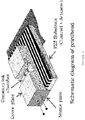
- the present invention relates to an apparatus and method for producing polymeric microparticles in which a plurality (e.g. an array) of droplet generators are configured to dispense liquid droplets into a common stream of a second liquid (the continuous phase).
- a plurality e.g. an array
- the stream of second liquid need not be in contact with a conduit or flow channel, but may take the form of a jet (i.e. a coherent stream of fluid projected into a surrounding medium from a nozzle).
- the droplets may be dispensed in parallel, spaced along the direction of flow of the stream of second liquid.
- Prior described methods envisage a 1:1 relationship between droplet generator and flow channel.
- the present invention provides an apparatus for producing solid polymeric microparticles, the apparatus comprising: a plurality of liquid droplet generators for forming liquid droplets of a first liquid, wherein the plurality of liquid droplet generators comprise at least one piezoelectric component operable to generate droplets; and a nozzle for forming a jet of a second liquid,wherein the plurality of liquid droplet generators and the nozzle are arranged relative to each other such that, in use, liquid droplets from the plurality of liquid droplet generators pass through a gas into said jet of second liquid, and wherein, in use, the plurality of liquid droplet generators are operable to produce liquid droplets at a frequency in the range 1 to 100 kHz per droplet generator.
- the droplet generators may operate in drop-on-demand mode.
- the apparatus may further comprise a signal generator operable to supply an electric field to the piezoelectric component.
- the plurality of liquid droplet generators are in the form of an inkjet printhead.
- the plurality of liquid droplet generators each comprise a droplet generator outlets and wherein the droplet generator outlets are in a line or an array.
- the line or array of droplet generator outlets may be substantially parallel to the jet direction of said nozzle.
- substantially parallel is taken to mean an offset of not more than 30° from parallel, optionally not more than 5° from parallel.
- the angle of offset may be determined, for example, by viewing the apparatus from above ("bird's eye view") and considering the line of the jet direction from the nozzle and the line formed by the droplet generator outlets and notionally extending these lines to their point of intersection.
- the jet direction from the nozzle will be in line with the line formed by the droplet generator outlets, when viewed from above (an example of this arrangement is depicted in Figure 3 ).
- the number of liquid droplet generator outlets is in the range 5 to 2500, optionally 256, 512 or 1024. In particular, the number of liquid droplet generator outlets may be in the range 100 to 1024.
- the plurality of liquid droplet generators are operable to generate liquid droplets having an individual droplet volume in the range 1 to 100 pL, optionally in the range 5 to 50 pL. In some cases, the plurality of liquid droplet generators are operable to produce liquid droplets at a frequency in the range 1 to 10 kHz.
- the apparatus further comprises a microparticle-receiving means for receiving solid microparticles dispersed in a jet of liquid.
- the microparticle-receiving means may comprise a conduit having an opening arranged such that, in use, the jet of second liquid enters said opening downstream of the region of the jet where the liquid droplets enter the jet of second liquid.
- the microparticle-receiving means comprises a tube having an opening that faces said nozzle.
- the tube may be formed of flexible or rigid material and may comprise an elbow bend.
- the microparticle-receiving means is able to convert the generally horizontal motion of the microparticle-containing jet into downward vertical motion for collection of the microparticles and/or separation of the microparticles from the second liquid.
- the microparticle-receiving means comprises a fluid removal means operable to remove fluid from the microparticle-receiving means and a microparticle collection means operable to remove microparticles from the microparticle-receiving means.
- the apparatus further comprises means for generating a flow of said second liquid through said nozzle.
- the means for generating flow may comprise a regulated pressure system for producing a pulseless flow of the liquid.
- the means for generating flow may comprise a reservoir for holding the second liquid, said reservoir having an outlet in fluid communication with said nozzle.
- the nozzle has a reduction in cross-sectional area in the direction of flow so as to increase the flow velocity of a liquid passing through the nozzle and thereby form a jet.
- the apparatus further comprises a camera for monitoring liquid droplets generated by said plurality of liquid droplet generators.
- the apparatus may further comprise a light source for illuminating liquid droplets generated by said plurality of liquid droplet generators.
- the light source may comprise an LED strobe electrically coordinated with the plurality of liquid droplet generators such that, in use, the camera is able to capture an image of liquid droplets ejected from the plurality of liquid droplet generators at a pre-determined (but typically user-adjustable) time period after ejection of said liquid droplets.
- the LED strobe may have an adjustable strobe delay, adjustable strobe intensity and/or adjustable pulse width settings, thereby allowing said pre-determined time period after ejection of said droplets to be adjusted.
- the apparatus further comprises at least one temperature regulator for controlling the temperature of liquid entering said plurality of liquid droplet generators and/or the temperature of liquid entering said nozzle.
- the at least one temperature regulator may comprise a first chiller for controlling the temperature of the first liquid entering the plurality of liquid droplet generators in the range of 5°C to 30°C, optionally in the range 12°C to 16°C or 16°C to 20°C.
- the at least one temperature regulator comprises a second chiller for controlling the temperature of the second liquid entering the nozzle in the range of 0°C to 20°C, optionally in the range 2°C to 8°C or 3°C to 9°C.
- the nozzle is arranged such that, in use, the jet is directed so as to define a horizontal line or arc that passes below the plurality of liquid droplet generators.
- the plurality of liquid droplet generators may be arranged such that, in use, the liquid droplets are ejected downwardly with an initial velocity and/or under the assistance of gravity, through said gas, into said jet of second liquid.
- the plurality of liquid droplet generators may be arranged such that, when viewed from above, the respective outlets of the plurality of liquid droplet generators are in line with and above the jet direction of said nozzle.
- the outlets of the liquid droplet generators are spaced-apart at equal intervals.
- the outlets of adjacent liquid droplet generators may be spaced-apart by between 0.1 and 0.2 mm, measured outlet centre to outlet centre.
- the plurality of liquid droplet generators are positioned relative to the nozzle such that the distance of travel of a liquid droplet from the outlet of a liquid droplet generator to the nearest point of the jet is in the range 2 to 10 mm, optionally 4 to 6 mm.
- the present invention provides a process for producing solid microparticles, the process comprising:
- the first liquid further comprises at least one (e.g. 1, 2, 3, 4, 5 or more different target materials) target material (also known as a "payload") which is desired to be encapsulated within the microparticles, the target material being incorporated in the first liquid as a particulate or in solution.
- target material comprises a pharmaceutically active agent or a precursor of a pharmaceutically active agent.
- the target material may be a pharmaceutically active agent for treatment of a tumour, a central nervous system (CNS) condition, an ocular condition, an infection (e.g. viral, bacterial or other pathogen) or an inflammatory condition (including autoinflammatory conditions).
- the target material may be a peptide, a hormone therapeutic, a chemotherapeutic or an immunosuppressant.
- the target material may comprise octreotide or a salt thereof (e.g. octreotide acetate), or ciclosporin A or a salt thereof.
- the target material may comprise a plurality of nanoparticles.
- the nanoparticles may have a pharmaceutically active agent or a precursor of a pharmaceutically active agent covalently or non-covalently (e.g. electrostatically) bound thereto (directly or via one or more linkers).
- the nanoparticles may, for example, be as described in PCT/EP2015/076364 filed 11 November 2015 , published as WO 2016/075211 A1 - the entire contents of which is expressly incorporated herein by reference).
- the plurality of liquid droplet generators comprising at least one piezoelectric component operable to generate droplets may operate in drop-on-demand mode.
- the respective outlets of the plurality of liquid droplet generators are substantially in line with said jet of second liquid such that the liquid droplets contact the jet of second liquid in parallel spaced along the jet of second liquid.
- the number of liquid droplet generator outlets is in the range 5 to 2500, such as 100 to 1200, optionally 256, 512 or 1024.
- the frequency of liquid droplet generation is in the range 1 to 10 kHz.
- the liquid droplets have an individual droplet volume in the range 1 to 100 pL, optionally 20 to 60 pL.
- the mean greatest dimension (typically the diameter) of the solid microparticles is in the range 1 to 200 ⁇ m, optionally 10 to 100 ⁇ m or 15 to 25 ⁇ m or 20 to 40 ⁇ m.
- the coefficient of variation of the greatest dimension of the microparticles is 0.1 or less, the coefficient of variation being the standard deviation of the greatest dimension of the microparticles divided by the mean greatest dimension.
- the ratio of the greatest dimension to the least dimension of the microparticles is in the range 2 to 1, optionally 1.1 to 1.01.
- the microparticles may be substantially spherical ("microspheres").
- the jet of second liquid is generated by providing a continuous, pulseless flow of said second liquid and passing said flow of second liquid through a nozzle which causes a reduction in the cross-sectional area available for flow and thereby increases the flow velocity of the second liquid, said nozzle terminating in an orifice from which the jet of second liquid emerges.
- the jet of second liquid passes through a gas (e.g. air) .
- a gas e.g. air
- the jet of second liquid is not in contact with any wall or channel for at least part of its length.
- the continuous phase is generally provided as a flow in a channel or a pool such as a stirred pool in an open-topped vessel.
- the part of the length of the jet not in contact with any wall or channel comprises a contact zone, said contact zone being the zone of the jet in which said liquid droplets make contact with said jet.
- the liquid droplets pass through gas (e.g. air) for a distance of 1 to 100 mm, optionally 2 to 10 mm before contacting said jet of second liquid.
- gas e.g. air
- the jet of second liquid flows substantially perpendicular to the direction of droplet ejection and substantially parallel to the longitudinal axis of the plurality of liquid droplet generator outlets.
- the plurality of liquid droplet generators are positioned above the jet of second liquid and said liquid droplets are ejected downwards towards the jet of second liquid with an initial velocity and/or under the assistance of gravity.
- the plurality of liquid droplet generators dispense liquid droplets from their respective outlets simultaneously.
- the liquid droplets may pass through gas in parallel before contacting said jet of second liquid.
- the flow velocity of the jet of second liquid and the frequency of liquid droplet generation are selected such that the liquid droplets and/or the solid microparticles do not coalesce.
- the flow rate of the jet of the second liquid may be in the range 10 to 500 mL/min, such as 20 to 200 mL/min or 20 to 100 mL/min.
- the process is carried out under aseptic conditions, optionally within a laminar flow cabinet. This is particularly suitable when the target material is a pharmaceutical and/or when the microparticles are intended for therapeutic or other clinical use.
- the relative position of the plurality of liquid droplet generators and the jet of the second liquid may be chosen to account for the direction and speed of air flow of the laminar flow cabinet, thereby causing the liquid droplets to contact the jet of the second liquid.
- the process of the invention further comprises capturing one or more images of at least one of said liquid droplets at a pre-determined time point after the at least one liquid droplet has been generated.
- the process may further comprise deriving from said one or more images at least one liquid droplet property selected from the group consisting of: droplet velocity, droplet volume, droplet radius and deviation of droplet from its initial trajectory.
- monitoring including continuous live monitoring
- process parameters such as droplet generation frequency, the flow rate of the jet of second liquid or the temperature of the first and/or second liquids in order to control the size and other properties of the microparticles produced.
- the temperature of the first liquid entering the plurality of liquid droplet generators is in the range of 5°C to 30°C, optionally in the range 12°C to 16°C or 16°C to 20°C.
- the temperature of the second liquid entering the nozzle is in the range of 0°C to 20°C, optionally in the range 2°C to 8°C or 3°C to 9°C.
- the solvent comprises dimethyl sulfoxide (DMSO).
- the second liquid comprises a mixture of water and an alcohol (e.g. tert-butanol) or water and a water-soluble organic compound other than an alcohol.
- the second liquid may be 15% w/w tertiary butanol in water.
- the polymer comprises a poly(lactide), a poly(glycolide), a polycaprolactone, a polyanhydride and/or a co-polymer of lactic acid and glycolic acid, or is any combination of said polymers or co-polymers.
- the polymer may comprise Resomer RG752H, Purasorb PDL 02A, Purasorb PDL 02, Purasorb PDL 04, Purasorb PDL 04A, Purasorb PDL 05, Purasorb PDL 05A Purasorb PDL 20, Purasorb PDL 20A; Purasorb PG 20; Purasorb PDLG 5004, Purasorb PDLG 5002, Purasorb PDLG 7502, Purasorb PDLG 5004A, Purasorb PDLG 5002A, Resomer RG755S, Resomer RG503, Resomer RG502, Resomer RG503H, Resomer RG502H, Resomer RG752, or any combination thereof.
- the process further comprises collecting the solid microparticles by separating the solid microparticles from the second liquid.
- the process may further comprise subjecting the microparticles to one or more post-production treatment steps selected from the group consisting of: washing, heating, drying, freeze-drying and sterilizing.
- the process further comprises formulating or packaging the microparticles into a pharmaceutical composition or delivery form.
- the microparticles may be combined with a pharmaceutically acceptable carrier, diluent or vehicle.
- the pharmaceutical composition or delivery form may be a depot injection.
- the process of the second aspect of the invention employs an apparatus in accordance with the first aspect of the invention.
- a liquid stream comprising a plurality of solid polymeric microparticles suspended in the liquid, wherein the flow rate of liquid stream is in the range 0.8 cm 3 /s to 5 cm 3 /s and the density of microparticles in the liquid stream is in the range 100000 microparticles/cm 3 to 750000 microparticles/cm 3 .
- This may be provided, for example, by having a liquid stream with a flow rate of between 50 mL/minute to 300 mL/min and ejecting into the stream liquid droplets at a firing rate of between 1000 Hz and 6000 Hz from each of 512 liquid droplet generator outlets.
- the liquid droplets solidify by the process of de-solvation (see above) and provide 512000 to 3072000 microparticles/second, which are carried by the flow of the liquid stream.
- the comparatively high density of microparticles in the flow results in more efficient microparticle production with reduced waste of continuous phase.
- microparticles of the liquid stream may be as defined in connection with the second aspect of the invention.
- the microparticles may encapsulate a target material selected from the group consisting of:
- the mean greatest dimension of the solid microparticles is in the range 1 to 200 ⁇ m, optionally 10 to 100 ⁇ m or 15 to 25 ⁇ m or 20 to 40 ⁇ m.
- the coefficient of variation of the greatest dimension of the microparticles may be 0.1 or less, the coefficient of variation being the standard deviation of the greatest dimension of the microparticles divided by the mean greatest dimension.
- the ratio of the greatest dimension to the least dimension of the microparticles may be in the range 2 to 1, optionally 1.1 to 1.01.
- the microparticles may be substantially spherical.
- the liquid stream may be in the form of a jet.
- the jet may be as defined in connection with the second aspect of the invention.
- the liquid stream of this aspect of the invention may be produced or producible using an apparatus according to the first aspect of the invention.
- Microparticles in accordance with the present invention may be in the form of solid beads. As used herein in connection with microparticles or beads, solid is intended to encompass a gel. Microparticles as used herein specifically include any polymeric particle or bead of micron scale (typically from 1 ⁇ m up to 999 ⁇ m in diameter). The microparticles may be of substantially spherical geometry (also referred to herein as "microspheres"). In particular, the ratio of the longest dimension to the shortest dimension of the microparticle may be not more than 5, 4, 3, 2, 1.9, 1.8, 1.7, 1.6, 1.5, 1.4, 1.3, 1.2, 1.1, 1.05 or not more than 1.01.
- a "jet” is a coherent stream of fluid that is projected into a surrounding medium from a nozzle or aperture.
- a jet of second liquid continuous phase
- the jet may define a flow path, at least part of which is not in contact with any solid wall, conduit or channel.
- the jet may define a flow path (e.g. a line or arc) that intersects with the path or paths of liquid droplets dispensed from the plurality of droplet generators.
- the jet may be a stream of the second liquid passing through air below the plurality of droplet generators, whereby liquid droplets dispensed from the droplet generators pass through the gas under the assistance of gravity into the stream of the second liquid and are carried by said stream of second liquid.
- surface tension of the second liquid contributes to the jet taking the form of coherent stream.
- the jet has a substantially circular cross-section.
- other cross sectional shapes e.g. flattened or oval-like are specifically contemplated and may be provided, e.g., by means of particular nozzle shapes.
- the polymer is typically a biocompatible polymer.
- Biocompatible is typically taken to mean compatible with living cells, tissues, organs, or systems, and posing minimal or no risk of injury, toxicity, or rejection by the immune system.
- polymers which may be used are polylactides (with a variety of end groups), such as Purasorb PDL 02A, Purasorb PDL 02, Purasorb PDL 04, Purasorb PDL 04A, Purasorb PDL 05, Purasorb PDL 05A Purasorb PDL 20, Purasorb PDL 20A; polyglycolides (with a variety of end groups), such as Purasorb PG 20; polycaprolactones; polyanhydrides, and copolymers of lactic acid and glycolic acid (with a variety of end groups, L:G ratios and molecular weight can be included), such as Purasorb PDLG 5004, Purasorb PDLG 5002, Purasorb PDLG 7502, Purasorb PDLG 5004A, Purasorb PDLG 500
- the solute is substantially insoluble in water (it is convenient to use water as the second liquid).
- the solvent is a water-miscible organic solvent, such as dimethyl sulfoxide (DMSO), n-methyl pyrrolidone, hexafluoroisopropanol, glycofurol, PEG200 and PEG400.
- the weight average molecular weight (MW) of the polymer may be from 4 to 700 kDaltons, particularly if the polymer comprises a poly (a-hydroxy) acid. If the polymer comprises a copolymer of lactic and glycolic acid (often called "PLGA"), said polymer may have a weight average molecular weight of from 4 to 120kDaltons, preferably of from 4 to 15kDaltons.
- PLGA copolymer of lactic and glycolic acid
- the polymer comprises a polylactide
- said polymer may have a weight average molecular weight of from 4 to 700kDaltons.
- the polymer may have an inherent viscosity of from 0.1-2 dl/g, particularly if the polymer comprises a poly (a-hydroxy) acid. If the polymer comprises a copolymer of lactic and glycolic acid (often called "PLGA"), said polymer may have. an inherent viscosity of from 0.1 to 1 dl/g, and optionally of from 0.14 to 0.22 dl/g. If the polymer comprises a polylactide, said polymer may have an inherent viscosity of from 0.1 to 2 dl/g, and optionally of from 0.15 to 0.25 dl/g.
- PLGA copolymer of lactic and glycolic acid
- the polymer comprises a polyglycolide
- said polymer may have an inherent viscosity of from 0.1 to 2 dl/g, and optionally of from 1.0 to 1.6 dl/g.
- the first liquid comprises a target material which is desired to be encapsulated within the solid microparticles.
- the process of the present invention may, in certain cases, not include a target material.
- the process may be used to produce placebo microparticles, e.g., for use as a negative control in an experiment or clinical trial.
- the target material (also known as the "payload”) may be incorporated in the first liquid as a particulate or may be dissolved.
- the target material may comprise a pharmaceutically active agent, or may be a precursor of a pharmaceutically active agent.
- the target material comprises a pharmaceutically active agent, or precursor (e.g. prodrug) thereof, for treatment of a tumour, a central nervous system (CNS) condition, an ocular condition, an infection or an inflammatory condition.
- the target material may comprise a peptide, a hormone therapeutic, a chemotherapeutic or an immunosuppressant.
- said target material comprises a plurality of nanoparticles (e.g. gold nanoparticles). When present, such nanoparticles may have a pharmaceutically active agent or a precursor thereof covalently or non-covalently bound thereto.
- Examples of pharmaceutically active agent include, for example, any agent that is suitable for parenteral delivery, including, without limitation, fertility drugs, hormone therapeutics , protein therapeutics, anti-infectives, antibiotics, antifungals, cancer drugs, pain-killers, vaccines, CNS drugs, and immunosupressants.
- Particular examples include octreotide or salt thereof (e.g. octreotide acetate) and ciclosporin A or a salt thereof.
- the delivery of drugs in polymer microparticles has particular advantages in the case of drugs which, for example, have poor water-solubility, high toxicity, poor absorption characteristics, although the invention is not limited to use with such agents.
- the active agent may be, for example, a small molecular drug, or a more complex molecule such as a polymeric molecule.
- the pharmaceutically active agent may comprise a peptide agent.
- peptide agent includes poly(amino acids), often referred to generally as “peptides”, “oligopeptides”, “polypeptides” and "proteins".
- Peptide agents which may be used in the method of the present invention include (but are not limited to) enzymes, cytokines, antibodies, vaccines, growth hormones and growth factors.
- the target material (especially in the case of a pharmaceutically active agent or a precursor thereof) may be provided in an amount of 2-60% w/w compared to the weight of the polymer, optionally from 5 to 40% w/w, further optionally from 5 to 30% w/w and more optionally from 5-15% w/w.
- the first liquid may comprise one or more tertiary structure alteration inhibitors.
- tertiary structure alteration inhibitors are: saccharides, compounds comprising saccharide moieties, polyols (such as glycol, mannitol, lactitol and sorbitol), solid or dissolved buffering agents (such as calcium carbonate and magnesium carbonate) and metal salts (such as CaCl 2 , MnCl 2 , NaCl and NiCl 2 ).
- the first liquid may comprise up to 25% w/w tertiary structure alteration inhibitors, the weight percentage of the tertiary structure alteration inhibitor being calculated as a percentage of the weight of the polymer.
- the first liquid may comprise from 0.1 to 10% w/w (optionally from 1 to 8% w/w and further optionally from 3 to 7% w/w) metal salt and 0.1 to 15% w/w (optionally from 0.5 to 6% w/w and further optionally from 1 to 4% w/w) polyol.
- the second liquid may comprise any liquid in which the solute (typically a polymer) is substantially insoluble.
- a liquid is sometimes referred to as an "anti-solvent".
- Suitable liquids may include, for example, water, methanol, ethanol, propanol (e.g. 1-propanol, 2-propanol), butanol (e.g.
- the second liquid preferably comprises water, optionally with one or more surface active agents, for example, alcohols, such as methanol, ethanol, propanol (e.g. 1-propanol, 2-propanol), butanol (e.g. 1-butanol, 2-butanol or tert-butanol), isopropyl alcohol, Polysorbate 20, Polysorbate 40, Polysorbate 60 and Polysorbate 80.
- surface active agents such as alcohols, reduce the surface tension of the second liquid receiving the droplets, which reduces the deformation of the droplets when they impact the second liquid, - thus decreasing the likelihood of non-spherical droplets forming. This is particularly important when the extraction of solvent from the droplet is rapid.
- the second liquid comprises water and one or more surface active agents
- the second liquid may comprise a surface active agent content of from 1 to 95% v/v, optionally from 1 to 30% v/v, optionally from 1 to 25% v/v, further optionally from 5% to 20% v/v and further more optionally from 10 to 20% v/v.
- the % volume of surface active agent is calculated relative to the volume of the second liquid.
- printhead or “inkjet printhead” may be a component, typically employed in inkjet printing or inkjet material deposition, which comprises one or more chambers that act as reservoirs for a fluid to be ejected and at least two nozzles through which droplets of the fluid are ejected by virtue of force applied by a piezoelectric material operating in drop-on-demand mode.
- the nozzles of the inkjet printhead may be arranged in a regular pattern, such as a single row or an array having more than one row.
- the inkjet printhead may be a commercially available "off the shelf” inkjet printhead used "as is” or may be adapted for use in the microparticle generating methods of the present invention or may be custom made for use in the microparticle generating methods of the present invention.
- An example of a printhead for use in accordance with the present invention is the Konica Minolta 512LH print head, e.g. KM512LH-010532.
- the present invention aims to provide consistent and precise encapsulation of active drug compounds within polymer microspheres designed to release the drug into the body in a controlled manner over a prolonged period of time.
- the present example employs drop-on-demand inkjet technology to produce droplets in the picolitre (pL) range.
- the technology has been proven to produce discrete, repeatable droplets at frequencies of several kHz across multiple nozzles.
- Optimisation of the pressure pulse is achieved by adjusting the magnitude and duration of the electrical field supplied.
- the temperature at the nozzle plate can also be controlled in order to alter the viscosity of the fluid at the point of ejection.
- Droplet formation is tracked using an advanced viewing system ("JetXpert") supplied by ImageXpert.
- the system includes a camera and LED strobe which is triggered each time a firing signal (5 Volt P-P Square Wave 50% duty cycle) is sent to the actuator of the droplet generator.
- a firing signal (5 Volt P-P Square Wave 50% duty cycle) is sent to the actuator of the droplet generator.
- the result is a static, monochromatic image of the ejected droplet at a pre-determined time period after ejection, which is refreshed over a pre-determined time allowing for monitoring of droplets potentially falling out of specification.
- This time period is known as the strobe delay and can be input to the software by a process operator.
- the delay is variable, and hence the entire droplet formation period is traceable.
- the system allows for viewing droplets "in motion” by assigning a Start value, End value and Step size via nanoseconds which in turn automatically starts increasing the strobe delay to follow the droplet formation and ejection path until
- the viewing system can be calibrated to allow the user to ascertain important properties of the ejected droplets; namely velocity (metres per second), volume (pL), radius ( ⁇ m) and its deviation from its original trajectory (values are provided via mean, standard deviation, minimum and maximum). These data can be automatically recorded in a spreadsheet to act as a batch record. Images and videos may also be taken when data is not being recorded
- the second fluid passes across the underside of the generator.
- the droplets are ejected into air, initially, before being captured by the horizontal cross flow of fluid (i.e. the jet), collecting all droplets from all nozzles in one stream.
- the flow beneath the droplet generator is laminar (i.e. the jet of second liquid defines a generally horizontal line or arc that passes under the droplet generator), as seen in Figure 3 .
- the present inventors have designed a nozzle containing an abrupt reduction to the circular cross-sectional area available for flow. This serves to increase the flow velocity in the region immediately below the generator, with the aim of ensuring ejected droplets do not coalesce.
- the velocity of the jet is such that droplets are immediately removed from the path of those behind them. Continuous, pulseless flow is provided by a regulated pressure system.
- the continuous phase nozzle is mounted on a bespoke bracket designed by the present inventors which attaches to the a custom aspect-ready framework to which is in turn attached the JetXpert peripherals.
- a receiving elbow Directly opposite the nozzle on the other side of the droplet generator is a receiving elbow to capture the stream which now contains solidified spheres.
- Both process fluids' temperatures are controlled by programmable chilling systems.
- the anti-solvent is chilled in-line upstream of the anti-solvent nozzle. At their point of contact, the continuous phase is 3-9°C.
- the dispersed phase is held at approximately 16°C in order to maintain the stability of the drug-loaded formulation, but also to avoid freezing when agitated through priming and vacuum changes.
- the above-described method of microparticle generation was found to produce a larger number of microparticles per unit time and a relatively lower volume of anti-solvent was required per microparticle produced when compared with the single droplet generator nozzle per channel method described in WO2012/042273 and WO2012/042274 .
- the number of microparticles produced is in the range 1024000 to 3072000 microparticles per second. The above-described method therefore provides greater potential for industrial-scale production and increased efficiency.
- the liquid stream containing the formed solid microparticles has a greater density of microparticles such that there is lower level of waste of the continuous phase for a given quantity of microparticles produced. Nevertheless, the microparticles produced were found to exhibit excellent uniformity, i.e. they were highly monodisperse.
- Example 1 A particular example of the process of microparticle production described above in Example 1 is the production of octreotide-loaded microspheres (Q-OctreotideTM) now described.
- Octreotide (also known by the brand name Sandostatin®, Novartis Pharmaceuticals) is an octapeptide that mimics somatostatin pharmacologically.
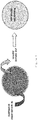
- Octreotide has the following chemical structure: Octreotide is used for the treatment of growth hormone producing tumours (acromegaly and gigantism), pituitary tumours that secrete thyroid stimulating hormone (thyrotropinoma), diarrhoea and flushing episodes associated with carcinoid syndrome, and diarrhoea in people with vasoactive intestinal peptide-secreting tumours (VIPomas).
- a master formulation is made up:
- the active solution is maintained at 12-16°C.
- KM512LH head was run with frequency set to 4kHz.
- the octreotide-loaded microspheres were collected using a bead harvester (see WO2013/014466 ), washed, freeze-dried and terminally sterilized (e.g. using gamma ray or E-beam sterilization).
- the octreotide-loaded microspheres were determined to be monodisperse and suitable for sustained release pharmaceutical use.
Landscapes
- Chemical & Material Sciences (AREA)
- Health & Medical Sciences (AREA)
- Organic Chemistry (AREA)
- Chemical Kinetics & Catalysis (AREA)
- Engineering & Computer Science (AREA)
- Veterinary Medicine (AREA)
- Medicinal Chemistry (AREA)
- Pharmacology & Pharmacy (AREA)
- Life Sciences & Earth Sciences (AREA)
- Animal Behavior & Ethology (AREA)
- General Health & Medical Sciences (AREA)
- Public Health (AREA)
- Bioinformatics & Cheminformatics (AREA)
- General Chemical & Material Sciences (AREA)
- Nuclear Medicine, Radiotherapy & Molecular Imaging (AREA)
- Dispersion Chemistry (AREA)
- Epidemiology (AREA)
- Biomedical Technology (AREA)
- Nanotechnology (AREA)
- Physics & Mathematics (AREA)
- Optics & Photonics (AREA)
- Oncology (AREA)
- Rheumatology (AREA)
- Neurosurgery (AREA)
- Mechanical Engineering (AREA)
- Communicable Diseases (AREA)
- Ophthalmology & Optometry (AREA)
- Pain & Pain Management (AREA)
- Neurology (AREA)
- Medicinal Preparation (AREA)
- Manufacturing Of Micro-Capsules (AREA)
- Particle Formation And Scattering Control In Inkjet Printers (AREA)
- Infusion, Injection, And Reservoir Apparatuses (AREA)
- Medicines That Contain Protein Lipid Enzymes And Other Medicines (AREA)
- Glanulating (AREA)
Priority Applications (1)
| Application Number | Priority Date | Filing Date | Title |
|---|---|---|---|
| PL16812959T PL3389840T3 (pl) | 2015-12-18 | 2016-12-16 | Sposób i aparatura do wytwarzania mikrocząstek |
Applications Claiming Priority (2)
| Application Number | Priority Date | Filing Date | Title |
|---|---|---|---|
| GB1522423.1A GB2551944B (en) | 2015-12-18 | 2015-12-18 | Microparticle production process and apparatus |
| PCT/EP2016/081436 WO2017103113A2 (en) | 2015-12-18 | 2016-12-16 | Microparticle production process and apparatus |
Publications (2)
| Publication Number | Publication Date |
|---|---|
| EP3389840A2 EP3389840A2 (en) | 2018-10-24 |
| EP3389840B1 true EP3389840B1 (en) | 2019-08-21 |
Family
ID=55311254
Family Applications (1)
| Application Number | Title | Priority Date | Filing Date |
|---|---|---|---|
| EP16812959.1A Active EP3389840B1 (en) | 2015-12-18 | 2016-12-16 | Microparticle production process and apparatus |
Country Status (13)
| Country | Link |
|---|---|
| US (2) | US10981131B2 (pt) |
| EP (1) | EP3389840B1 (pt) |
| JP (1) | JP7112325B2 (pt) |
| KR (1) | KR20180111800A (pt) |
| CN (1) | CN108602035B (pt) |
| AU (1) | AU2016369412B2 (pt) |
| BR (1) | BR112018012340B1 (pt) |
| CA (1) | CA3008554A1 (pt) |
| ES (1) | ES2749949T3 (pt) |
| GB (1) | GB2551944B (pt) |
| MX (1) | MX2018007466A (pt) |
| PL (1) | PL3389840T3 (pt) |
| WO (1) | WO2017103113A2 (pt) |
Families Citing this family (7)
| Publication number | Priority date | Publication date | Assignee | Title |
|---|---|---|---|---|
| GB201522441D0 (en) | 2015-12-18 | 2016-02-03 | Midatech Pharma Wales Ltd | Sustained release cyclosporine-loaded microparticles |
| DK3436188T3 (da) * | 2016-03-30 | 2020-12-21 | Iamfluidics Holding B V | Fremgangsmåde og indretning til fremstilling af enkelt-dråber i bevægelse, sammensatte dråber og formstyrede (sammensatte) partikler eller fibre |
| JP2022508519A (ja) * | 2018-10-01 | 2022-01-19 | ニューマ・リスパイラトリー・インコーポレイテッド | 電子呼吸作動式エアロゾル吸入デバイスを介した肺系統への低表面張力組成物の送達 |
| KR102230329B1 (ko) * | 2019-05-15 | 2021-03-22 | 경희대학교 산학협력단 | 마이크로 입자의 대량 생산 방법 및 이를 통해 제조된 마이크로 입자 |
| JP2021028305A (ja) | 2019-08-09 | 2021-02-25 | 株式会社リコー | 粒子、医薬組成物、及び粒子の製造方法 |
| GB202002727D0 (en) * | 2020-02-26 | 2020-04-08 | Midatech Pharma Wales Ltd | Microparticle production platform, method of producing microparticles and a pharmaceutical composition |
| JP2021147330A (ja) | 2020-03-16 | 2021-09-27 | 株式会社リコー | 徐放性粒子及びその製造方法 |
Family Cites Families (29)
| Publication number | Priority date | Publication date | Assignee | Title |
|---|---|---|---|---|
| US4663093A (en) * | 1985-12-23 | 1987-05-05 | The United States Of America As Represented By The United States Department Of Energy | Preparation of nuclear fuel spheres by flotation-internal gelation |
| US4981625A (en) | 1988-03-14 | 1991-01-01 | California Institute Of Technology | Monodisperse, polymeric microspheres produced by irradiation of slowly thawing frozen drops |
| DE4338212C2 (de) * | 1993-11-10 | 1996-01-18 | Nukem Gmbh | Verfahren und Vorrichtung zur Herstellung von aus Kunststoff bestehenden Partikeln |
| DE19750679B4 (de) * | 1997-11-15 | 2004-10-21 | Institut für Lebensmittelwissenschaft, Lehrstuhl für Lebensmittelverfahrenstechnik | Verfahren zum Erzeugen von kaltgesprühten, verfestigten, lagerstabilen und rieselfähigen Mikrokapselsystemen sowie deren Verwendung |
| JPH11244683A (ja) * | 1998-02-27 | 1999-09-14 | Japan Atom Energy Res Inst | 湿式造粒方法及び装置 |
| ATE262976T1 (de) * | 1998-03-07 | 2004-04-15 | Inotech Ag | Verfahren und vorrichtung zum verkapseln von mikrobiellen, pflanzlichen und tierischen zellen bzw. von biologischen und chemischen substanzen |
| JP2000269423A (ja) | 1999-03-16 | 2000-09-29 | Toshiba Microelectronics Corp | 半導体集積回路 |
| DE10012550B4 (de) * | 2000-03-15 | 2006-06-29 | Air Liquide Gmbh | Vorrichtung und Verfahren zum Pellet-Gefrieren |
| KR100902625B1 (ko) * | 2000-08-15 | 2009-06-15 | 더 보드 오브 트러스티즈 오브 더 유니버시티 오브 일리노이 | 마이크로입자 |
| DE10157413A1 (de) * | 2001-11-23 | 2003-06-05 | Rieter Automatik Gmbh | Vorrichtung zur Vertropfung von in geschmolzenem Zustand befindlichen Materialien, insbesondere Kunststoffen |
| US6998074B1 (en) * | 2002-08-30 | 2006-02-14 | Microfab Technologies, Inc. | Method for forming polymer microspheres |
| GB0300339D0 (en) * | 2003-01-08 | 2003-02-05 | Bradford Particle Design Ltd | Particle formation |
| GB0300338D0 (en) * | 2003-01-08 | 2003-02-05 | Bradford Particle Design Ltd | Particle formation |
| JP4334316B2 (ja) * | 2003-10-16 | 2009-09-30 | 原子燃料工業株式会社 | 重ウラン酸アンモニウム粒子製造装置 |
| US20080019904A1 (en) * | 2004-06-29 | 2008-01-24 | Koninklijke Philips Electronics, N.V. | System For Manufacturing Micro-Sheres |
| DE102005018949A1 (de) * | 2005-04-18 | 2006-10-19 | Ami-Agrolinz Melamine International Gmbh | Harnstoffpartikel, Verfahren zu dessen Herstellung und dessen Verwendung |
| US20100311638A1 (en) * | 2006-10-27 | 2010-12-09 | Paul Tiege | Method for Altering the Shape of Polymer Particles |
| EP2020261A1 (en) * | 2007-07-20 | 2009-02-04 | Nederlandse Organisatie voor toegepast- natuurwetenschappelijk onderzoek TNO | Multi component particle generating system |
| CN102215821B (zh) * | 2007-10-23 | 2013-05-08 | 皇家飞利浦电子股份有限公司 | 用于制备聚合物微颗粒的方法 |
| EP2222284B1 (en) | 2007-11-19 | 2020-07-01 | Capsulated Systems Inc. | Prolonged release of local anesthetics using microparticles and surgery applications |
| JP2011020055A (ja) * | 2009-07-16 | 2011-02-03 | Seiko Epson Corp | ゲル製造方法およびゲル製造装置 |
| DE102009048321A1 (de) * | 2009-10-05 | 2011-04-07 | Messer Group Gmbh | Vorrichtung und Verfahren zum Pelletieren oder Granulieren eines flüssigen oder pastösen Stoffes |
| US20110185631A1 (en) * | 2010-02-03 | 2011-08-04 | Kellogg Brown & Root Llc | Systems and Methods of Pelletizing Heavy Hydrocarbons |
| GB201016436D0 (en) * | 2010-09-30 | 2010-11-17 | Q Chip Ltd | Method of making solid beads |
| GB201016433D0 (en) * | 2010-09-30 | 2010-11-17 | Q Chip Ltd | Apparatus and method for making solid beads |
| GB201113007D0 (en) | 2011-07-28 | 2011-09-14 | Q Chip Ltd | Bead collection device and method |
| US9195156B2 (en) | 2013-02-25 | 2015-11-24 | Ricoh Company, Ltd. | Particulate material production method, and particulate material production apparatus |
| GB2512309A (en) | 2013-03-25 | 2014-10-01 | Thermo Electron Mfg Ltd | Apparatus and method for liquid sample introduction |
| GB201420080D0 (en) | 2014-11-11 | 2014-12-24 | Midatech Ltd And Q Chip Ltd | Sustained release encapsulated nanoparticles |
-
2015
- 2015-12-18 GB GB1522423.1A patent/GB2551944B/en active Active
-
2016
- 2016-12-16 US US15/780,211 patent/US10981131B2/en active Active
- 2016-12-16 CA CA3008554A patent/CA3008554A1/en active Pending
- 2016-12-16 MX MX2018007466A patent/MX2018007466A/es active IP Right Grant
- 2016-12-16 CN CN201680074439.6A patent/CN108602035B/zh active Active
- 2016-12-16 AU AU2016369412A patent/AU2016369412B2/en active Active
- 2016-12-16 ES ES16812959T patent/ES2749949T3/es active Active
- 2016-12-16 PL PL16812959T patent/PL3389840T3/pl unknown
- 2016-12-16 EP EP16812959.1A patent/EP3389840B1/en active Active
- 2016-12-16 KR KR1020187020613A patent/KR20180111800A/ko not_active Application Discontinuation
- 2016-12-16 BR BR112018012340-4A patent/BR112018012340B1/pt active IP Right Grant
- 2016-12-16 JP JP2018531164A patent/JP7112325B2/ja active Active
- 2016-12-16 WO PCT/EP2016/081436 patent/WO2017103113A2/en active Application Filing
-
2021
- 2021-03-17 US US17/204,676 patent/US11794158B2/en active Active
Non-Patent Citations (1)
| Title |
|---|
| None * |
Also Published As
| Publication number | Publication date |
|---|---|
| CN108602035B (zh) | 2021-10-15 |
| JP7112325B2 (ja) | 2022-08-03 |
| MX2018007466A (es) | 2018-11-14 |
| AU2016369412A1 (en) | 2018-06-14 |
| BR112018012340B1 (pt) | 2021-03-09 |
| JP2019507003A (ja) | 2019-03-14 |
| KR20180111800A (ko) | 2018-10-11 |
| PL3389840T3 (pl) | 2020-01-31 |
| EP3389840A2 (en) | 2018-10-24 |
| WO2017103113A3 (en) | 2017-08-24 |
| GB2551944B (en) | 2021-09-01 |
| US20190193037A1 (en) | 2019-06-27 |
| US20210268461A1 (en) | 2021-09-02 |
| WO2017103113A2 (en) | 2017-06-22 |
| CN108602035A (zh) | 2018-09-28 |
| US11794158B2 (en) | 2023-10-24 |
| BR112018012340A2 (pt) | 2018-12-04 |
| GB2551944A (en) | 2018-01-10 |
| ES2749949T3 (es) | 2020-03-24 |
| US10981131B2 (en) | 2021-04-20 |
| AU2016369412B2 (en) | 2021-04-01 |
| GB201522423D0 (en) | 2016-02-03 |
| CA3008554A1 (en) | 2017-06-22 |
Similar Documents
| Publication | Publication Date | Title |
|---|---|---|
| US11794158B2 (en) | Microparticle production process and apparatus | |
| US9259701B2 (en) | Method for making solid beads | |
| US9156016B2 (en) | Apparatus and method for making solid beads | |
| JP2019507003A5 (pt) | ||
| US20230077586A1 (en) | Microparticle Production Platform, Method of Producing Microparticles and a Pharmaceutical Composition | |
| GB2594652A (en) | Microparticle liquid stream |
Legal Events
| Date | Code | Title | Description |
|---|---|---|---|
| STAA | Information on the status of an ep patent application or granted ep patent |
Free format text: STATUS: UNKNOWN |
|
| STAA | Information on the status of an ep patent application or granted ep patent |
Free format text: STATUS: THE INTERNATIONAL PUBLICATION HAS BEEN MADE |
|
| PUAI | Public reference made under article 153(3) epc to a published international application that has entered the european phase |
Free format text: ORIGINAL CODE: 0009012 |
|
| STAA | Information on the status of an ep patent application or granted ep patent |
Free format text: STATUS: REQUEST FOR EXAMINATION WAS MADE |
|
| 17P | Request for examination filed |
Effective date: 20180702 |
|
| AK | Designated contracting states |
Kind code of ref document: A2 Designated state(s): AL AT BE BG CH CY CZ DE DK EE ES FI FR GB GR HR HU IE IS IT LI LT LU LV MC MK MT NL NO PL PT RO RS SE SI SK SM TR |
|
| AX | Request for extension of the european patent |
Extension state: BA ME |
|
| DAV | Request for validation of the european patent (deleted) | ||
| DAX | Request for extension of the european patent (deleted) | ||
| GRAP | Despatch of communication of intention to grant a patent |
Free format text: ORIGINAL CODE: EPIDOSNIGR1 |
|
| STAA | Information on the status of an ep patent application or granted ep patent |
Free format text: STATUS: GRANT OF PATENT IS INTENDED |
|
| INTG | Intention to grant announced |
Effective date: 20190410 |
|
| GRAS | Grant fee paid |
Free format text: ORIGINAL CODE: EPIDOSNIGR3 |
|
| GRAA | (expected) grant |
Free format text: ORIGINAL CODE: 0009210 |
|
| STAA | Information on the status of an ep patent application or granted ep patent |
Free format text: STATUS: THE PATENT HAS BEEN GRANTED |
|
| AK | Designated contracting states |
Kind code of ref document: B1 Designated state(s): AL AT BE BG CH CY CZ DE DK EE ES FI FR GB GR HR HU IE IS IT LI LT LU LV MC MK MT NL NO PL PT RO RS SE SI SK SM TR |
|
| REG | Reference to a national code |
Ref country code: GB Ref legal event code: FG4D |
|
| REG | Reference to a national code |
Ref country code: CH Ref legal event code: EP |
|
| REG | Reference to a national code |
Ref country code: DE Ref legal event code: R096 Ref document number: 602016019180 Country of ref document: DE |
|
| REG | Reference to a national code |
Ref country code: AT Ref legal event code: REF Ref document number: 1169065 Country of ref document: AT Kind code of ref document: T Effective date: 20190915 |
|
| REG | Reference to a national code |
Ref country code: IE Ref legal event code: FG4D |
|
| REG | Reference to a national code |
Ref country code: NL Ref legal event code: FP |
|
| REG | Reference to a national code |
Ref country code: SE Ref legal event code: TRGR |
|
| REG | Reference to a national code |
Ref country code: LT Ref legal event code: MG4D |
|
| PG25 | Lapsed in a contracting state [announced via postgrant information from national office to epo] |
Ref country code: FI Free format text: LAPSE BECAUSE OF FAILURE TO SUBMIT A TRANSLATION OF THE DESCRIPTION OR TO PAY THE FEE WITHIN THE PRESCRIBED TIME-LIMIT Effective date: 20190821 Ref country code: LT Free format text: LAPSE BECAUSE OF FAILURE TO SUBMIT A TRANSLATION OF THE DESCRIPTION OR TO PAY THE FEE WITHIN THE PRESCRIBED TIME-LIMIT Effective date: 20190821 Ref country code: HR Free format text: LAPSE BECAUSE OF FAILURE TO SUBMIT A TRANSLATION OF THE DESCRIPTION OR TO PAY THE FEE WITHIN THE PRESCRIBED TIME-LIMIT Effective date: 20190821 Ref country code: PT Free format text: LAPSE BECAUSE OF FAILURE TO SUBMIT A TRANSLATION OF THE DESCRIPTION OR TO PAY THE FEE WITHIN THE PRESCRIBED TIME-LIMIT Effective date: 20191223 Ref country code: NO Free format text: LAPSE BECAUSE OF FAILURE TO SUBMIT A TRANSLATION OF THE DESCRIPTION OR TO PAY THE FEE WITHIN THE PRESCRIBED TIME-LIMIT Effective date: 20191121 Ref country code: BG Free format text: LAPSE BECAUSE OF FAILURE TO SUBMIT A TRANSLATION OF THE DESCRIPTION OR TO PAY THE FEE WITHIN THE PRESCRIBED TIME-LIMIT Effective date: 20191121 |
|
| PG25 | Lapsed in a contracting state [announced via postgrant information from national office to epo] |
Ref country code: LV Free format text: LAPSE BECAUSE OF FAILURE TO SUBMIT A TRANSLATION OF THE DESCRIPTION OR TO PAY THE FEE WITHIN THE PRESCRIBED TIME-LIMIT Effective date: 20190821 Ref country code: AL Free format text: LAPSE BECAUSE OF FAILURE TO SUBMIT A TRANSLATION OF THE DESCRIPTION OR TO PAY THE FEE WITHIN THE PRESCRIBED TIME-LIMIT Effective date: 20190821 Ref country code: GR Free format text: LAPSE BECAUSE OF FAILURE TO SUBMIT A TRANSLATION OF THE DESCRIPTION OR TO PAY THE FEE WITHIN THE PRESCRIBED TIME-LIMIT Effective date: 20191122 Ref country code: RS Free format text: LAPSE BECAUSE OF FAILURE TO SUBMIT A TRANSLATION OF THE DESCRIPTION OR TO PAY THE FEE WITHIN THE PRESCRIBED TIME-LIMIT Effective date: 20190821 Ref country code: IS Free format text: LAPSE BECAUSE OF FAILURE TO SUBMIT A TRANSLATION OF THE DESCRIPTION OR TO PAY THE FEE WITHIN THE PRESCRIBED TIME-LIMIT Effective date: 20191221 |
|
| REG | Reference to a national code |
Ref country code: AT Ref legal event code: MK05 Ref document number: 1169065 Country of ref document: AT Kind code of ref document: T Effective date: 20190821 |
|
| REG | Reference to a national code |
Ref country code: ES Ref legal event code: FG2A Ref document number: 2749949 Country of ref document: ES Kind code of ref document: T3 Effective date: 20200324 |
|
| PG25 | Lapsed in a contracting state [announced via postgrant information from national office to epo] |
Ref country code: EE Free format text: LAPSE BECAUSE OF FAILURE TO SUBMIT A TRANSLATION OF THE DESCRIPTION OR TO PAY THE FEE WITHIN THE PRESCRIBED TIME-LIMIT Effective date: 20190821 Ref country code: AT Free format text: LAPSE BECAUSE OF FAILURE TO SUBMIT A TRANSLATION OF THE DESCRIPTION OR TO PAY THE FEE WITHIN THE PRESCRIBED TIME-LIMIT Effective date: 20190821 Ref country code: RO Free format text: LAPSE BECAUSE OF FAILURE TO SUBMIT A TRANSLATION OF THE DESCRIPTION OR TO PAY THE FEE WITHIN THE PRESCRIBED TIME-LIMIT Effective date: 20190821 Ref country code: DK Free format text: LAPSE BECAUSE OF FAILURE TO SUBMIT A TRANSLATION OF THE DESCRIPTION OR TO PAY THE FEE WITHIN THE PRESCRIBED TIME-LIMIT Effective date: 20190821 |
|
| PG25 | Lapsed in a contracting state [announced via postgrant information from national office to epo] |
Ref country code: SK Free format text: LAPSE BECAUSE OF FAILURE TO SUBMIT A TRANSLATION OF THE DESCRIPTION OR TO PAY THE FEE WITHIN THE PRESCRIBED TIME-LIMIT Effective date: 20190821 Ref country code: SM Free format text: LAPSE BECAUSE OF FAILURE TO SUBMIT A TRANSLATION OF THE DESCRIPTION OR TO PAY THE FEE WITHIN THE PRESCRIBED TIME-LIMIT Effective date: 20190821 Ref country code: IS Free format text: LAPSE BECAUSE OF FAILURE TO SUBMIT A TRANSLATION OF THE DESCRIPTION OR TO PAY THE FEE WITHIN THE PRESCRIBED TIME-LIMIT Effective date: 20200224 Ref country code: CZ Free format text: LAPSE BECAUSE OF FAILURE TO SUBMIT A TRANSLATION OF THE DESCRIPTION OR TO PAY THE FEE WITHIN THE PRESCRIBED TIME-LIMIT Effective date: 20190821 |
|
| REG | Reference to a national code |
Ref country code: DE Ref legal event code: R097 Ref document number: 602016019180 Country of ref document: DE |
|
| PLBE | No opposition filed within time limit |
Free format text: ORIGINAL CODE: 0009261 |
|
| STAA | Information on the status of an ep patent application or granted ep patent |
Free format text: STATUS: NO OPPOSITION FILED WITHIN TIME LIMIT |
|
| PG2D | Information on lapse in contracting state deleted |
Ref country code: IS |
|
| 26N | No opposition filed |
Effective date: 20200603 |
|
| REG | Reference to a national code |
Ref country code: BE Ref legal event code: MM Effective date: 20191231 |
|
| PG25 | Lapsed in a contracting state [announced via postgrant information from national office to epo] |
Ref country code: MC Free format text: LAPSE BECAUSE OF FAILURE TO SUBMIT A TRANSLATION OF THE DESCRIPTION OR TO PAY THE FEE WITHIN THE PRESCRIBED TIME-LIMIT Effective date: 20190821 |
|
| PG25 | Lapsed in a contracting state [announced via postgrant information from national office to epo] |
Ref country code: LU Free format text: LAPSE BECAUSE OF NON-PAYMENT OF DUE FEES Effective date: 20191216 |
|
| PG25 | Lapsed in a contracting state [announced via postgrant information from national office to epo] |
Ref country code: BE Free format text: LAPSE BECAUSE OF NON-PAYMENT OF DUE FEES Effective date: 20191231 |
|
| PG25 | Lapsed in a contracting state [announced via postgrant information from national office to epo] |
Ref country code: CY Free format text: LAPSE BECAUSE OF FAILURE TO SUBMIT A TRANSLATION OF THE DESCRIPTION OR TO PAY THE FEE WITHIN THE PRESCRIBED TIME-LIMIT Effective date: 20190821 |
|
| PG25 | Lapsed in a contracting state [announced via postgrant information from national office to epo] |
Ref country code: HU Free format text: LAPSE BECAUSE OF FAILURE TO SUBMIT A TRANSLATION OF THE DESCRIPTION OR TO PAY THE FEE WITHIN THE PRESCRIBED TIME-LIMIT; INVALID AB INITIO Effective date: 20161216 Ref country code: MT Free format text: LAPSE BECAUSE OF FAILURE TO SUBMIT A TRANSLATION OF THE DESCRIPTION OR TO PAY THE FEE WITHIN THE PRESCRIBED TIME-LIMIT Effective date: 20190821 |
|
| PG25 | Lapsed in a contracting state [announced via postgrant information from national office to epo] |
Ref country code: SI Free format text: LAPSE BECAUSE OF FAILURE TO SUBMIT A TRANSLATION OF THE DESCRIPTION OR TO PAY THE FEE WITHIN THE PRESCRIBED TIME-LIMIT Effective date: 20190821 |
|
| PG25 | Lapsed in a contracting state [announced via postgrant information from national office to epo] |
Ref country code: MK Free format text: LAPSE BECAUSE OF FAILURE TO SUBMIT A TRANSLATION OF THE DESCRIPTION OR TO PAY THE FEE WITHIN THE PRESCRIBED TIME-LIMIT Effective date: 20190821 |
|
| PGFP | Annual fee paid to national office [announced via postgrant information from national office to epo] |
Ref country code: PL Payment date: 20221214 Year of fee payment: 7 |
|
| PGFP | Annual fee paid to national office [announced via postgrant information from national office to epo] |
Ref country code: NL Payment date: 20231106 Year of fee payment: 8 |
|
| PGFP | Annual fee paid to national office [announced via postgrant information from national office to epo] |
Ref country code: GB Payment date: 20231117 Year of fee payment: 8 |
|
| PGFP | Annual fee paid to national office [announced via postgrant information from national office to epo] |
Ref country code: TR Payment date: 20231110 Year of fee payment: 8 Ref country code: SE Payment date: 20231115 Year of fee payment: 8 Ref country code: IT Payment date: 20231107 Year of fee payment: 8 Ref country code: IE Payment date: 20231107 Year of fee payment: 8 Ref country code: FR Payment date: 20231117 Year of fee payment: 8 Ref country code: DE Payment date: 20231107 Year of fee payment: 8 |
|
| PGFP | Annual fee paid to national office [announced via postgrant information from national office to epo] |
Ref country code: ES Payment date: 20240222 Year of fee payment: 8 |
|
| PGFP | Annual fee paid to national office [announced via postgrant information from national office to epo] |
Ref country code: CH Payment date: 20240101 Year of fee payment: 8 |