EP3388247A1 - Système d'usinage pour une pluralité de pièces à usiner différentes - Google Patents
Système d'usinage pour une pluralité de pièces à usiner différentes Download PDFInfo
- Publication number
- EP3388247A1 EP3388247A1 EP18165285.0A EP18165285A EP3388247A1 EP 3388247 A1 EP3388247 A1 EP 3388247A1 EP 18165285 A EP18165285 A EP 18165285A EP 3388247 A1 EP3388247 A1 EP 3388247A1
- Authority
- EP
- European Patent Office
- Prior art keywords
- area
- processing
- input
- workpiece
- processing system
- Prior art date
- Legal status (The legal status is an assumption and is not a legal conclusion. Google has not performed a legal analysis and makes no representation as to the accuracy of the status listed.)
- Granted
Links
- 238000003754 machining Methods 0.000 title claims description 16
- 238000012545 processing Methods 0.000 claims abstract description 142
- 238000001514 detection method Methods 0.000 claims description 6
- 238000000034 method Methods 0.000 description 12
- 238000004891 communication Methods 0.000 description 8
- 230000008569 process Effects 0.000 description 8
- 238000004140 cleaning Methods 0.000 description 6
- 230000004913 activation Effects 0.000 description 5
- 239000000463 material Substances 0.000 description 5
- 230000008901 benefit Effects 0.000 description 4
- 239000003086 colorant Substances 0.000 description 3
- 238000005520 cutting process Methods 0.000 description 3
- 239000006260 foam Substances 0.000 description 3
- 230000006870 function Effects 0.000 description 3
- 238000004519 manufacturing process Methods 0.000 description 3
- 238000012790 confirmation Methods 0.000 description 2
- 238000012937 correction Methods 0.000 description 2
- 230000008878 coupling Effects 0.000 description 2
- 238000010168 coupling process Methods 0.000 description 2
- 238000005859 coupling reaction Methods 0.000 description 2
- 238000011156 evaluation Methods 0.000 description 2
- 238000012423 maintenance Methods 0.000 description 2
- 239000002184 metal Substances 0.000 description 2
- 238000007639 printing Methods 0.000 description 2
- 238000004064 recycling Methods 0.000 description 2
- 238000003860 storage Methods 0.000 description 2
- 229910000831 Steel Inorganic materials 0.000 description 1
- 230000003213 activating effect Effects 0.000 description 1
- 239000012790 adhesive layer Substances 0.000 description 1
- 238000013459 approach Methods 0.000 description 1
- 230000009286 beneficial effect Effects 0.000 description 1
- 230000005540 biological transmission Effects 0.000 description 1
- 230000008859 change Effects 0.000 description 1
- 238000006243 chemical reaction Methods 0.000 description 1
- 239000002131 composite material Substances 0.000 description 1
- 238000010276 construction Methods 0.000 description 1
- 238000000151 deposition Methods 0.000 description 1
- 238000013461 design Methods 0.000 description 1
- 238000010586 diagram Methods 0.000 description 1
- 239000000428 dust Substances 0.000 description 1
- 238000000605 extraction Methods 0.000 description 1
- 239000000835 fiber Substances 0.000 description 1
- 238000003780 insertion Methods 0.000 description 1
- 230000037431 insertion Effects 0.000 description 1
- 238000007689 inspection Methods 0.000 description 1
- 238000009434 installation Methods 0.000 description 1
- 230000010354 integration Effects 0.000 description 1
- 238000010147 laser engraving Methods 0.000 description 1
- 230000007257 malfunction Effects 0.000 description 1
- 238000005259 measurement Methods 0.000 description 1
- 239000002245 particle Substances 0.000 description 1
- 230000001681 protective effect Effects 0.000 description 1
- 239000011241 protective layer Substances 0.000 description 1
- 238000000926 separation method Methods 0.000 description 1
- 239000010959 steel Substances 0.000 description 1
- 238000012546 transfer Methods 0.000 description 1
- 230000001960 triggered effect Effects 0.000 description 1
- 230000000007 visual effect Effects 0.000 description 1
Images

Classifications
-
- B—PERFORMING OPERATIONS; TRANSPORTING
- B23—MACHINE TOOLS; METAL-WORKING NOT OTHERWISE PROVIDED FOR
- B23K—SOLDERING OR UNSOLDERING; WELDING; CLADDING OR PLATING BY SOLDERING OR WELDING; CUTTING BY APPLYING HEAT LOCALLY, e.g. FLAME CUTTING; WORKING BY LASER BEAM
- B23K26/00—Working by laser beam, e.g. welding, cutting or boring
- B23K26/36—Removing material
- B23K26/362—Laser etching
-
- B—PERFORMING OPERATIONS; TRANSPORTING
- B23—MACHINE TOOLS; METAL-WORKING NOT OTHERWISE PROVIDED FOR
- B23K—SOLDERING OR UNSOLDERING; WELDING; CLADDING OR PLATING BY SOLDERING OR WELDING; CUTTING BY APPLYING HEAT LOCALLY, e.g. FLAME CUTTING; WORKING BY LASER BEAM
- B23K26/00—Working by laser beam, e.g. welding, cutting or boring
- B23K26/02—Positioning or observing the workpiece, e.g. with respect to the point of impact; Aligning, aiming or focusing the laser beam
- B23K26/03—Observing, e.g. monitoring, the workpiece
- B23K26/032—Observing, e.g. monitoring, the workpiece using optical means
-
- B—PERFORMING OPERATIONS; TRANSPORTING
- B23—MACHINE TOOLS; METAL-WORKING NOT OTHERWISE PROVIDED FOR
- B23K—SOLDERING OR UNSOLDERING; WELDING; CLADDING OR PLATING BY SOLDERING OR WELDING; CUTTING BY APPLYING HEAT LOCALLY, e.g. FLAME CUTTING; WORKING BY LASER BEAM
- B23K26/00—Working by laser beam, e.g. welding, cutting or boring
- B23K26/352—Working by laser beam, e.g. welding, cutting or boring for surface treatment
-
- B—PERFORMING OPERATIONS; TRANSPORTING
- B23—MACHINE TOOLS; METAL-WORKING NOT OTHERWISE PROVIDED FOR
- B23K—SOLDERING OR UNSOLDERING; WELDING; CLADDING OR PLATING BY SOLDERING OR WELDING; CUTTING BY APPLYING HEAT LOCALLY, e.g. FLAME CUTTING; WORKING BY LASER BEAM
- B23K26/00—Working by laser beam, e.g. welding, cutting or boring
- B23K26/36—Removing material
- B23K26/361—Removing material for deburring or mechanical trimming
-
- B—PERFORMING OPERATIONS; TRANSPORTING
- B23—MACHINE TOOLS; METAL-WORKING NOT OTHERWISE PROVIDED FOR
- B23K—SOLDERING OR UNSOLDERING; WELDING; CLADDING OR PLATING BY SOLDERING OR WELDING; CUTTING BY APPLYING HEAT LOCALLY, e.g. FLAME CUTTING; WORKING BY LASER BEAM
- B23K26/00—Working by laser beam, e.g. welding, cutting or boring
- B23K26/36—Removing material
- B23K26/38—Removing material by boring or cutting
-
- B—PERFORMING OPERATIONS; TRANSPORTING
- B23—MACHINE TOOLS; METAL-WORKING NOT OTHERWISE PROVIDED FOR
- B23K—SOLDERING OR UNSOLDERING; WELDING; CLADDING OR PLATING BY SOLDERING OR WELDING; CUTTING BY APPLYING HEAT LOCALLY, e.g. FLAME CUTTING; WORKING BY LASER BEAM
- B23K26/00—Working by laser beam, e.g. welding, cutting or boring
- B23K26/70—Auxiliary operations or equipment
- B23K26/702—Auxiliary equipment
-
- B—PERFORMING OPERATIONS; TRANSPORTING
- B23—MACHINE TOOLS; METAL-WORKING NOT OTHERWISE PROVIDED FOR
- B23K—SOLDERING OR UNSOLDERING; WELDING; CLADDING OR PLATING BY SOLDERING OR WELDING; CUTTING BY APPLYING HEAT LOCALLY, e.g. FLAME CUTTING; WORKING BY LASER BEAM
- B23K37/00—Auxiliary devices or processes, not specially adapted to a procedure covered by only one of the preceding main groups
- B23K37/02—Carriages for supporting the welding or cutting element
- B23K37/0294—Transport carriages or vehicles
-
- B—PERFORMING OPERATIONS; TRANSPORTING
- B41—PRINTING; LINING MACHINES; TYPEWRITERS; STAMPS
- B41D—APPARATUS FOR THE MECHANICAL REPRODUCTION OF PRINTING SURFACES FOR STEREOTYPE PRINTING; SHAPING ELASTIC OR DEFORMABLE MATERIAL TO FORM PRINTING SURFACES
- B41D7/00—Shaping elastic or deformable material, e.g. rubber, plastics material, to form printing surfaces
-
- B—PERFORMING OPERATIONS; TRANSPORTING
- B41—PRINTING; LINING MACHINES; TYPEWRITERS; STAMPS
- B41K—STAMPS; STAMPING OR NUMBERING APPARATUS OR DEVICES
- B41K1/00—Portable hand-operated devices without means for supporting or locating the articles to be stamped, i.e. hand stamps; Inking devices or other accessories therefor
- B41K1/36—Details
- B41K1/38—Inking devices; Stamping surfaces
-
- G—PHYSICS
- G05—CONTROLLING; REGULATING
- G05B—CONTROL OR REGULATING SYSTEMS IN GENERAL; FUNCTIONAL ELEMENTS OF SUCH SYSTEMS; MONITORING OR TESTING ARRANGEMENTS FOR SUCH SYSTEMS OR ELEMENTS
- G05B15/00—Systems controlled by a computer
- G05B15/02—Systems controlled by a computer electric
-
- G—PHYSICS
- G06—COMPUTING; CALCULATING OR COUNTING
- G06F—ELECTRIC DIGITAL DATA PROCESSING
- G06F3/00—Input arrangements for transferring data to be processed into a form capable of being handled by the computer; Output arrangements for transferring data from processing unit to output unit, e.g. interface arrangements
- G06F3/01—Input arrangements or combined input and output arrangements for interaction between user and computer
- G06F3/048—Interaction techniques based on graphical user interfaces [GUI]
- G06F3/0481—Interaction techniques based on graphical user interfaces [GUI] based on specific properties of the displayed interaction object or a metaphor-based environment, e.g. interaction with desktop elements like windows or icons, or assisted by a cursor's changing behaviour or appearance
- G06F3/0482—Interaction with lists of selectable items, e.g. menus
-
- G—PHYSICS
- G06—COMPUTING; CALCULATING OR COUNTING
- G06F—ELECTRIC DIGITAL DATA PROCESSING
- G06F3/00—Input arrangements for transferring data to be processed into a form capable of being handled by the computer; Output arrangements for transferring data from processing unit to output unit, e.g. interface arrangements
- G06F3/01—Input arrangements or combined input and output arrangements for interaction between user and computer
- G06F3/048—Interaction techniques based on graphical user interfaces [GUI]
- G06F3/0484—Interaction techniques based on graphical user interfaces [GUI] for the control of specific functions or operations, e.g. selecting or manipulating an object, an image or a displayed text element, setting a parameter value or selecting a range
- G06F3/04847—Interaction techniques to control parameter settings, e.g. interaction with sliders or dials
-
- G—PHYSICS
- G06—COMPUTING; CALCULATING OR COUNTING
- G06K—GRAPHICAL DATA READING; PRESENTATION OF DATA; RECORD CARRIERS; HANDLING RECORD CARRIERS
- G06K19/00—Record carriers for use with machines and with at least a part designed to carry digital markings
- G06K19/06—Record carriers for use with machines and with at least a part designed to carry digital markings characterised by the kind of the digital marking, e.g. shape, nature, code
- G06K19/06009—Record carriers for use with machines and with at least a part designed to carry digital markings characterised by the kind of the digital marking, e.g. shape, nature, code with optically detectable marking
- G06K19/06018—Record carriers for use with machines and with at least a part designed to carry digital markings characterised by the kind of the digital marking, e.g. shape, nature, code with optically detectable marking one-dimensional coding
- G06K19/06028—Record carriers for use with machines and with at least a part designed to carry digital markings characterised by the kind of the digital marking, e.g. shape, nature, code with optically detectable marking one-dimensional coding using bar codes
-
- G—PHYSICS
- G06—COMPUTING; CALCULATING OR COUNTING
- G06T—IMAGE DATA PROCESSING OR GENERATION, IN GENERAL
- G06T7/00—Image analysis
- G06T7/0002—Inspection of images, e.g. flaw detection
- G06T7/0004—Industrial image inspection
- G06T7/001—Industrial image inspection using an image reference approach
-
- B—PERFORMING OPERATIONS; TRANSPORTING
- B23—MACHINE TOOLS; METAL-WORKING NOT OTHERWISE PROVIDED FOR
- B23K—SOLDERING OR UNSOLDERING; WELDING; CLADDING OR PLATING BY SOLDERING OR WELDING; CUTTING BY APPLYING HEAT LOCALLY, e.g. FLAME CUTTING; WORKING BY LASER BEAM
- B23K2101/00—Articles made by soldering, welding or cutting
- B23K2101/007—Marks, e.g. trade marks
-
- B—PERFORMING OPERATIONS; TRANSPORTING
- B23—MACHINE TOOLS; METAL-WORKING NOT OTHERWISE PROVIDED FOR
- B23K—SOLDERING OR UNSOLDERING; WELDING; CLADDING OR PLATING BY SOLDERING OR WELDING; CUTTING BY APPLYING HEAT LOCALLY, e.g. FLAME CUTTING; WORKING BY LASER BEAM
- B23K2101/00—Articles made by soldering, welding or cutting
- B23K2101/34—Coated articles, e.g. plated or painted; Surface treated articles
- B23K2101/35—Surface treated articles
-
- Y—GENERAL TAGGING OF NEW TECHNOLOGICAL DEVELOPMENTS; GENERAL TAGGING OF CROSS-SECTIONAL TECHNOLOGIES SPANNING OVER SEVERAL SECTIONS OF THE IPC; TECHNICAL SUBJECTS COVERED BY FORMER USPC CROSS-REFERENCE ART COLLECTIONS [XRACs] AND DIGESTS
- Y02—TECHNOLOGIES OR APPLICATIONS FOR MITIGATION OR ADAPTATION AGAINST CLIMATE CHANGE
- Y02P—CLIMATE CHANGE MITIGATION TECHNOLOGIES IN THE PRODUCTION OR PROCESSING OF GOODS
- Y02P90/00—Enabling technologies with a potential contribution to greenhouse gas [GHG] emissions mitigation
- Y02P90/02—Total factory control, e.g. smart factories, flexible manufacturing systems [FMS] or integrated manufacturing systems [IMS]
Definitions
- the invention relates to a processing system, as described in the preamble of claim 1.
- a laser plotter for engraving, marking and / or inscribing a workpiece in which a plurality of, in particular two lasers are arranged in a housing of the laser plotter.
- the control takes place via a software running in a control unit, wherein a graphic and / or text is created on an external component, in particular a computer, which is transferred to the control unit of the laser plotter, which converts the transferred data from a stored database ,
- the assignment of the different steel sources takes place in the form of colors or color codes, wherein a correction value for the different positions, in particular height correction value for compensating the different focal positions or focal lengths of the different beam sources are stored in the database for a wide variety of colors.
- the disadvantage here is that in this system, a specialist for positioning and adjustment is necessary because only editing data are stored in the database.
- a laser plotter known, which is connected to an external component, in particular a computer.
- This laser plotter is used in that an ink pad with a composite part arranged therein, in particular a foam, is inserted into the processing room, whereupon predetermined separation joints are produced by cutting the foam, so that the individual foam part produced can be impregnated with different colors.
- a specialist staff is required, since an exact positioning and adjustment of the starting point for the cutting process are required.
- connection can be established by means of mobile phones to a computer connected to a printing device. It can be commissioned by sending a defined e-mail in the form of a form an automatic print job, which is automatically processed by the computer.
- the disadvantage here is that in such a system, although different labels, graphics can be assigned, but only one type of product can be generated or edited.
- a system is also out of the WO 2011/056345 A2 in which brands, in particular dog tags, can be engraved.
- a display element is present on the stand A Longe device, on which two sides, in particular front and rear side of the editable dog tag are shown, so that they can label and select the customer on the keyboard.
- the dog tag is subsequently or previously inserted by the customer in a receiving element and inserted into the device. So that only original recording elements are used, they have a corresponding barcode.
- Another disadvantage is that only a specific product can be produced.
- the skilled person places a workpiece, in particular a so-called blank, which is formed from a flexible rubber, into the processing device, whereupon a manual and or automatic positioning of the processing device, in particular a beam source of a laser, takes place.
- the specialist personnel then starts the machining process so that a negative impression of the stamp imprint created by the specialist on the computer is generated on the blank.
- the specialist takes the blank and cleans it of the processing residues.
- the negative stamp imprint on the printing plate support, on the already an adhesive layer is arranged, glued.
- the disadvantage here is that in such a procedure, the customer can not take the stamp directly, but this can pick up later or is sent to him. In addition, the customer can also take no influence in the creation of the stamp, as this is created by professionals and not directly from the customer.
- WO 2011/151604 A From the WO 2011/151604 A is a processing system for engraving trailers, especially chain trailers, known.
- a handwritten text or graphics is generated via a stylus on an input device connected to the processing device, which is then transmitted to a computer. From the computer then the processing device in which the trailer is inserted, controlled so that the handwritten text or graphics engraved in the trailer.
- the disadvantage here is that only a single machining process, in particular for engraving trailers, can be performed with the system.
- a processing system in which above the processing area an attached input and display element is arranged, via which a user can perform his input for engraving a trailer, in particular a heart pendant. Furthermore, the processing system has a movable receiving device in the processing area in which the trailer is positioned. For this purpose, the receiving device in a loading position, in which the receiving device partially protrudes from the housing of the processing system, moved, so that the trailer can be inserted into the receiving device.
- the recording device is moved to edit in the processing position below the input and display element.
- the receiving device is again moved to remove the trailer.
- a disadvantage of such systems is that only one task, namely the production of a photopolymer stamp plate, can be carried out with the processing device.
- the object of the invention is to provide a processing system and a method in which the user-friendliness is substantially increased. At the same time the maintenance of the systems or system should be kept as low as possible. Another object is to remedy the disadvantages of the prior art as possible.
- the invention is achieved by a processing system in which on the display element 11, the reading system (27) is integrated, wherein the reading system (27) for detecting the workpiece (9) via a on the workpiece (9) attached code (29) is integrated, and the data stored for this workpiece (9) can be called up by an operator software on an input device (11) or display element (11).
- the code is formed by a bar code or a QR code, as this commercial system, which are also used by other applications, such as a warehouse, the billing system, etc., are used ,
- a bar code or a QR code which are also used by other applications, such as a warehouse, the billing system, etc.
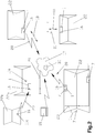
- FIG. 1 to 4 is a processing system 1 or processing unit 1 shown with a variety of components or structures.
- the processing system 1 Has a housing 2, in which the various components are integrated.
- the processing system 1 comprises At least one processing area 3, a control area 4, an input area 4a and optionally a receiving area 5 and / or presentation area 5.
- the individual arrangements of the components in the housing 2 is not limited to the presentation, but the components to others Positions in the housing 2 can be arranged.
- the housing 2 is preferably made of metal, in particular sheet metal, and has a plurality of doors, so that easy accessibility of the components arranged behind it is possible.
- a power supply unit 6 is arranged, from which the individual components can be supplied with energy.
- the power supply unit 6 is connected via a connecting cable (not shown) to a public power supply network (not shown).
- a public power supply network not shown.
- an emergency power system (not shown) is integrated, which is preferably activated automatically when the public power grid supplies no more energy. This ensures that, in the event of a power failure, the processing system 1 or at least the essential elements are still supplied with energy at least over a certain period of time, so that settings, machining operations or the like already made can be terminated and / or stored.
- the communication system 7 is used to output orders entered by a user and / or to have a visual printout of the input for inspection, ie that upon use of the processing system 1, a written confirmation or order can be issued which the user himself can use or the user can make a printout of his input created for preview in order to not be able to postpone it before it is implemented.
- a scanning device is arranged, via which, for example, the signed confirmation or the job can be scanned.
- the scanning device is used to scan, for example, graphics, layouts, images, company logos, which can be used for later processing.
- one or more additional modules with components integrated therein to be coupled to the housing 2 of the processing system 1.
- these are attached to the side walls of the housing 2.
- a subsequent extension of the processing system 1 is possible.
- a module may have as a component a scanner, which is set up, for example, on the module or is integrated in such a way that it can be easily operated by users from above by opening a cover.
- a module can be used as a warehouse for workpieces 9 or paper.
- a recycling system 8 is arranged in the housing 2 of the processing system 1.
- the recycling system 2 has a collecting container and a throw-in opening, through which residues of a machined workpiece 9 or blanks 9 can be inserted.
- a cleaning system 10 in particular an extraction system, integrated, which is activated on the one hand during a machining operation in the processing area 3 and on the other hand after a machining operation over a defined period of time for cleaning the workpiece 9.
- the cleaning system 10 is preferably designed such that during a machining process, the air sucks in the region of the workpiece to be machined 9, so that no odor nuisance for the user or operator arise when opening the processing room.
- the cleaning system 10 After completion of the machining process, the cleaning system 10 automatically switches, for example, via a valve flap (not shown) to the cleaning function for the user, so that the latter can now clean the workpiece 9 via a hose (not shown) with a suction brush fastened thereto and thus sucked off the dust particles can be. So that no odor nuisance occurs in the installation area, the cleaning system 10 is equipped with appropriate filters.
- Essential in such a processing system 1 is that several different workpieces 9 or blanks 9 can be processed or processed with a single device, the operation of the device or the processing system 1 has been simplified so that only an operator or a customer independently can work with the processing system 1. That means that for the local care no Skilled personnel for the processing device 1 is present, but only a trained operator, in particular seller of a department store.
- a detachable input device 11 or display element 11 of the input area 4a to which an operator software, also referred to below as "Trodesign", is installed, is arranged on the processing system 1.
- a corresponding with the operator software control software also referred to as "JobControl”, integrated, and that connected by connecting the display element 11 with the processing system 1 or by activation via a button 12 on the display element 11, the processing system 1 with this display element 11 is, that is, that the display element 11 is independent of the processing system 1, ie when removed display element 11, operated or operable so that you can work with the installed on the display element 11 operator software and only by deliberate coupling or connecting to the processing system 1 the Display element 11 is integrated into the processing system 1.
- the user has the ability to remove the display element 11 from the processing unit 1 and make his input in peace.
- the display element 11 may remain positioned on the processing system 1 and directly the input can be made.
- the so-called display element 11 serves as an input device, which preferably has a touch function, ie that an input to the display element 11 can be made by touching the surface. It is also possible that a plurality of display elements 11 can be used simultaneously, which are operated simultaneously by different users, since the display elements 11 can be operated independently of the processing unit 1.
- the contact device 13 for contacting, in particular for insertion, arranged.
- the contact device 13 is arranged on a sliding board 14, wherein the sliding board 14 is designed to cover the processing area 3, in particular for covering a portion of the processing area 3.
- the sliding board 14 may be equipped with corresponding sensors, so that activation of the processing system 1 is possible only by closing the sliding board 14, whereas it is interrupted during opening during a working process.
- the power supply in particular the charging of the display element 11 via the contact device 13 takes place.
- the activation of the processing system 1 is carried out by connecting the display element 11 to the contact device 13 or wirelessly by connecting via an operation of the corresponding hard- or software-executed button 12.
- the processing area 3 is formed by a laser plotter 15.
- the laser plotter 15 is for engraving, marking, cutting and manufacturing for different workpieces 9, in particular stamp plates blanks 9, signs, mobile phones, tablet computers, pens, sticks, computer accessories, such as cases, bags, etc., educated.
- the processing area 3 of the laser plotter 15 is designed such that in the processing area 3 of the laser plotter 15, a processing insert 15a, (schematically in FIG Fig. 3 indicated) is inserted or arranged.
- the processing insert 15a is formed such that a plurality of different workpieces 9 or blanks 9 can be positioned on a processing insert 15a, ie, for example, on a processing insert 15a a stamp plate blank 9, a shield (not shown) or an additional element for other workpieces 9, such as, for example, pens, sticks, etc., can be positioned so that the processing insert 15a need not be exchanged for these different workpieces 9.
- a processing insert 15a can be seen in detail from the concurrent Austrian priority application.
- the user creates a desired processing operation via the operator software, whereupon the processing operation is transferred to a control device, in particular to a control software, and is converted by this so that a Control of the processing device 1, in particular the Laserplotters 15, is carried out for performing the desired machining operation, whereupon the workpiece 9 in the processing apparatus 1, in particular on a processing insert 15a, positioned and the processing process can be started.
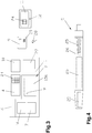
- connection system 16 for connecting the processing system 1, in particular the individual area, arranged with a parent network 17, in particular an Internet, the Connection system 16 for transmitting and receiving data 18 (shown schematically by an arrow) is formed, as shown schematically in FIG Fig. 2 is shown.
- the connection system 16 is designed for manual or automatic connection setup of the processing device 1 or processing system 1, or that from an external component 19, such as a computer, a connection via the connection system 16 is automatically activated or possible.
- the connection system 16 can also be integrated in the control unit 4 or the communication system 7.
- connection to the parent network 17 can be wirelessly via radio 20 or via a cable 21, in particular network or telephone cable or fiber optic cable, for example, a shop 22 or department store 22.
- a so-called Internet stick or data stick can be used.
- the connection system 16 interacts with the communication system 7, since the Internet stick can be simply plugged into the computer, in particular to a USB interface, of the communication system 7. If the processing system 1 is equipped with the connection system 16, then a separate identification number, in particular IP number, assigned, so that the processing unit 1 can be addressed directly.
- a plurality of processing systems 1, which are connected to one another via a cable 23, in particular a network cable 23, to be located in the shop 22 or large department store 22, wherein only a single processing system 1 is equipped with the connection system 16 the further processing system 1 can also be activated or controlled.
- the internal data exchange preferably takes place via the communication system 7 of each processing system 1.
- connection system 16 Through the use of the connection system 16 it is achieved that the processing system 1 can send data or receive external data. As a result, remote maintenance can also be carried out, for example, via the external component 19, since all data or systems can be accessed via the data connection. It is particularly advantageous that software updates are sent via the higher-level network, so that all processing systems 1 in use can be kept in a uniform state. Thus, software updates or malfunctions can be remedied very quickly by such updates.
- the processing system 1 is equipped with a database 24, ie that in the input area, in particular on the display element 11, and / or the control area 4, a database 24 is integrated, stored in the data of the workpieces to be processed 9 are, as shown schematically in Fig. 3 is shown.
- a database 24 is integrated, stored in the data of the workpieces to be processed 9 are, as shown schematically in Fig. 3 is shown.
- the data include, for example, the workpiece designation or type designation, a graphic image of the workpiece 9, the length, width and height of the workpiece 9, etc.
- processing areas 25 or engraving areas 25 are stored for the differently stored workpieces 9, so that the User can specifically activate the stored engraving 25 and can fill with appropriate texts or graphics, as in a workpiece 9 in the form of a pen 26 in Fig. 4 is shown.
- the novel processing systems 1 are equipped with such a database 24 for depositing workpieces 9, wherein for the workpieces 9 at least one processing region 25 is defined.
- a database 24 for depositing workpieces 9, wherein for the workpieces 9 at least one processing region 25 is defined.
- the workpiece 9 or type designation the graphical representation, the length, width and height of the workpiece 9, the material of the workpiece 9 or the material range at different Materials used, as well as at least one processing area 25, in particular an engraving area, as well as a start or zero point and / or reference point for the processing device 1, in particular the laser plotter 15, etc. deposited.
- the detection of the products, in particular of the workpieces 9, preferably takes place at the manufacturer or lessor of the processing system 1 itself, wherein the updating of the database 24 via the connection system 16 takes place, ie, if a user wants to edit a new product or workpiece 9 for the first time or if a new product or workpiece 9 comes on the market, this product is sent to the Monle or the manufacturer, who then recorded all data of the product and processed so that it can then be integrated into the database 24 and for the Selection is available. This is advantageous in that it must be ensured when first using a new product, which areas may be edited and which not.
- the input device or the display element 11b is equipped with a connection system 16, as shown schematically in FIG Fig. 2 is shown.
- a connection system 16 as shown schematically in FIG Fig. 2 is shown.
- the display element 11b can be spatially separated from the site of the processing unit 1 or processing system 1 can be used or used.
- Fig. 2 can thereby be operated in a shop 22a, a processing system 1 with an associated display element 11a, wherein in another, preferably adjacent store 22b, the display element 11b is operated or operable so that the customer in the shop 22b with the display element 11b create corresponding processing processes via the operator software.
- a job message is created and sent to an operator of the store 22a with the processing system 1.
- This order message for example, an activation of a beeper and / or SMS and / or email to a mobile phone, computer and / or activation of an information light on the processing system 1 done so that the operator can immediately recognize that an external processing has been received. It is also possible for all information to be contained and displayed in the order message, so that the operator can load the corresponding workpiece 9.
- a display element 11 in which a display element 11 is additionally operated in another store 22 or department store 22, it is preferred that the display element 11 is equipped with a connection system 16 for data exchange with a further connection system 16 in the processing system 1, the location-independent Display element 11 automatically suggests or selects the connection with the nearest processing system 1.
- a selection list of the obvious processing systems 1 can be retrieved or displayed, wherein the utilization or processing time for performing a processing process and / or the distance to the location of the display element 11 is shown.
- the customer can see how long it takes at which location, until his product is completed.
- the customer can select the processing system 1 which is best for him from the selection list so that the data is subsequently sent to him.
- a reading system 27 is integrated in the processing system 1 or on the display element 11.
- the reading system 27 is formed for example by a bar code scanner 28, a QR scanner, laser scanner, etc., or software technology by a corresponding app on the display element 11, wherein the scanner 28 is installed as a handheld device or in the housing 2 ,
- the user thus only needs to scan or record the code 29, in particular bar code or QR code, attached to the workpiece 9 or product with the reading system 27, in particular the scanner 28 or a camera on the display element 11 (not shown) , whereupon workpiece recognition takes place on the basis of the recognized code 29, since the code 29 is stored in the database 24 for the corresponding workpiece 9.
- the operator software then calls the corresponding product or workpiece 9 and is then updated with the data of the workpiece 9, so that the user only has to enter the texts or graphics in the processing areas 25. For this purpose, it is possible that a graphical representation of the product is displayed on the operator software, the deposited processing areas 25 are marked accordingly.
- the processing system 1 can also be designed in such a way that the control area 4 and / or input area 4a for automatic recognition of the workpiece 9 stored in the database 24 is formed by detecting the inserted workpiece 9. This can be done such that an automatic recognition of the workpiece 9 by detecting the length, the width and the height of the workpiece 9 takes place, so that due to the stored data for the workpiece 9, a corresponding evaluation is performed.
- the system is used in such a way that the Users in the operator software selects a product group, such as smartphone, tablet PC, smartphone cases, etc., so that due to the determination of the length, width and height of the workpiece 9 now due to the different dimensions of the manufacturer, the workpiece 9 or product and type is more easily recognizable or recognized and the data can be loaded, that is, by specifying a product group, the choice is reduced in the database, so that the most accurate detection of the product is possible.
- the detection can take place, for example, via a measurement in the processing area 3 or a scan of the product.
- a camera for receiving the processing area 9 or the workpiece 9 is arranged for automatic detection of the workpiece 9, ie that, for example, the inserted workpiece 9 from a processing area 3 associated camera (not shown) generates an image which then compared with the stored graphical images to the individual workpieces 9 and thus a corresponding evaluation is made.
- the display element 11 has a camera (not shown), with which the user takes an image of the product or workpiece 9 and this is then compared with the stored images.
- several images of the products, in particular all views, are preferably also stored in the database 24.
- the user or user is presented with a list of the most near or most loved products stored, so that he can subsequently select the corresponding product. It is also possible for the user to set the product or the workpiece 9 manually despite installed automatic recognition or without it, again preferably only those products of a product group being displayed to the user whom he selects, so that the selection of the products is simplified that is, the user first selects a product group, for example, smartphone, tablet PC, stamp, etc., on which only those products associated with those product groups are displayed. As a result, the number of products to be selected can be reduced user-friendly.
- the database 24 can be processed by the operator or seller in order to make a corresponding adjustment to the shop 22 or department store 22, in particular the product range.
- the operator or seller can call and activate or deactivate the individual workpieces 9, ie, the operator or seller adapts the workpieces 9 which can be called in the database 24 to the sales assortment of the shop 22, so that only those workpieces 9 can be called up, which are actually sold.
- this can also be done via the code 29 of the workpieces 9, for example, only the code 29 of the sales items, in particular the workpieces 9, is scanned so that subsequently only the scanned workpieces 9 are retrievable.
- a corresponding learning mode is activated, in which the sales range is entered.
- a newly acquired product in particular the data for this, to be uploaded by the manufacturer in a cloud 29, whereupon the individual processing system 1 independently updates the database 24 at defined times performs.
- updates to the operating system or other software updates or data may be stored in the cloud 29, which are automatically or manually retrieved by the processing systems 1.
- cloud storage 29 have the advantage that at any time data, software, etc. can be uploaded and they are available at any time. Thus, updates can be made in various continents of the world at those times when there is no operation of the store 22 or department store 22 so as not to disturb the operation of the facility.
- a warehouse management is integrated, so that the corresponding in the shop 22 to be purchased workpieces 9, in particular the stamp plate blanks 9 and / or the stamps for this or the accessories, etc., the inventory, ie the number of existing quantities of the product, is entered, which is reduced after a corresponding machining process for this product.
- a goods order is requested from processing system 1.
- processing system 1 directly via the connection system 16, a goods order to the manufacturer or supplier via the parent network 17, especially the Internet, be discontinued or the required goods order is displayed on the display element 11 or the processing system 1, so that the operator or seller activate this and can send.
- This warehouse management can in turn be activated or deactivated for the differently stored workpieces 9 in the database 24.
- any order addresses for the different workpieces 9 can be deposited.
Landscapes
- Engineering & Computer Science (AREA)
- Physics & Mathematics (AREA)
- Optics & Photonics (AREA)
- Mechanical Engineering (AREA)
- Plasma & Fusion (AREA)
- Theoretical Computer Science (AREA)
- General Physics & Mathematics (AREA)
- General Engineering & Computer Science (AREA)
- Human Computer Interaction (AREA)
- Manufacturing & Machinery (AREA)
- Computer Vision & Pattern Recognition (AREA)
- Quality & Reliability (AREA)
- Automation & Control Theory (AREA)
- General Factory Administration (AREA)
- Numerical Control (AREA)
- Electrical Discharge Machining, Electrochemical Machining, And Combined Machining (AREA)
- Management, Administration, Business Operations System, And Electronic Commerce (AREA)
Priority Applications (1)
| Application Number | Priority Date | Filing Date | Title |
|---|---|---|---|
| PL18165285T PL3388247T3 (pl) | 2014-01-10 | 2015-01-07 | Układ przetwarzania dla wielu różnych przedmiotów obrabianych |
Applications Claiming Priority (3)
| Application Number | Priority Date | Filing Date | Title |
|---|---|---|---|
| ATA50017/2014A AT514339A2 (de) | 2013-05-15 | 2014-01-10 | Bearbeitungssystem für mehrere unterschiedliche Werkstücke |
| PCT/AT2015/050003 WO2015103654A2 (fr) | 2014-01-10 | 2015-01-07 | Système d'usinage pour plusieurs pièces à usiner différentes |
| EP15706138.3A EP3092129B1 (fr) | 2014-01-10 | 2015-01-07 | Système d'usinage pour plusieurs pièces à usiner différentes |
Related Parent Applications (1)
| Application Number | Title | Priority Date | Filing Date |
|---|---|---|---|
| EP15706138.3A Division EP3092129B1 (fr) | 2014-01-10 | 2015-01-07 | Système d'usinage pour plusieurs pièces à usiner différentes |
Publications (2)
| Publication Number | Publication Date |
|---|---|
| EP3388247A1 true EP3388247A1 (fr) | 2018-10-17 |
| EP3388247B1 EP3388247B1 (fr) | 2019-08-07 |
Family
ID=52577566
Family Applications (4)
| Application Number | Title | Priority Date | Filing Date |
|---|---|---|---|
| EP18165284.3A Active EP3388246B1 (fr) | 2014-01-10 | 2015-01-07 | Système d'usinage pour une pluralité de pièces à usiner différentes |
| EP18165285.0A Active EP3388247B1 (fr) | 2014-01-10 | 2015-01-07 | Système d'usinage pour une pluralité de pièces à usiner différentes |
| EP18165286.8A Active EP3388248B1 (fr) | 2014-01-10 | 2015-01-07 | Système d'usinage pour plusieurs pièces à usiner différentes et procédé correspondant |
| EP15706138.3A Active EP3092129B1 (fr) | 2014-01-10 | 2015-01-07 | Système d'usinage pour plusieurs pièces à usiner différentes |
Family Applications Before (1)
| Application Number | Title | Priority Date | Filing Date |
|---|---|---|---|
| EP18165284.3A Active EP3388246B1 (fr) | 2014-01-10 | 2015-01-07 | Système d'usinage pour une pluralité de pièces à usiner différentes |
Family Applications After (2)
| Application Number | Title | Priority Date | Filing Date |
|---|---|---|---|
| EP18165286.8A Active EP3388248B1 (fr) | 2014-01-10 | 2015-01-07 | Système d'usinage pour plusieurs pièces à usiner différentes et procédé correspondant |
| EP15706138.3A Active EP3092129B1 (fr) | 2014-01-10 | 2015-01-07 | Système d'usinage pour plusieurs pièces à usiner différentes |
Country Status (6)
| Country | Link |
|---|---|
| US (1) | US10456868B2 (fr) |
| EP (4) | EP3388246B1 (fr) |
| CA (1) | CA2936113C (fr) |
| ES (1) | ES2743513T3 (fr) |
| PL (4) | PL3092129T3 (fr) |
| WO (1) | WO2015103654A2 (fr) |
Families Citing this family (12)
| Publication number | Priority date | Publication date | Assignee | Title |
|---|---|---|---|---|
| ES2743513T3 (es) | 2014-01-10 | 2020-02-19 | Trotec Laser Gmbh | Sistema de tratamiento para varios materiales diferentes |
| AT517322A1 (de) | 2015-06-10 | 2016-12-15 | Trodat Gmbh | Stempel und Abdruckeinheit, insbesondere als Ersatzteil für einen Stempel |
| AT517328A1 (de) | 2015-06-10 | 2016-12-15 | Trodat Gmbh | Stempel, ein Stempelkissen und eine Verschlusskappe |
| AT517321A1 (de) | 2015-06-10 | 2016-12-15 | Trodat Gmbh | Stempel |
| USD823378S1 (en) | 2015-06-10 | 2018-07-17 | Trodat Gmbh | Hand stamp |
| AT517318A1 (de) | 2015-06-10 | 2016-12-15 | Trodat Gmbh | Stempel und Abdruckeinheit |
| USD847899S1 (en) | 2015-12-10 | 2019-05-07 | Trodat Gmbh | Hand stamp |
| AT518735A1 (de) | 2016-06-09 | 2017-12-15 | Trodat Gmbh | Antriebseinheit, Bandeinheit, Brücke, Mitnehmer und Stempel hierfür |
| AT519177B1 (de) | 2016-10-06 | 2019-04-15 | Trotec Laser Gmbh | Verfahren zum Gravieren, Markieren und/oder Beschriften eines Werkstückes mit |
| AT523912B1 (de) * | 2020-04-24 | 2022-01-15 | Trotec Laser Gmbh | Verfahren zum Betreiben und Steuern einer Laservorrichtung für das Gravieren, Markieren, Beschriften und/oder Schneiden eines vorzugsweiser flachen Werkstückes |
| CN114260578B (zh) * | 2021-12-22 | 2024-03-22 | 华天科技(南京)有限公司 | 一种同时镭射多种印章的方法 |
| EP4364916A1 (fr) * | 2022-11-02 | 2024-05-08 | SCM Group S.p.A. | Système de commande pour une machine d'usinage de pièces, machine associée et procédé de fonctionnement de la machine |
Citations (11)
| Publication number | Priority date | Publication date | Assignee | Title |
|---|---|---|---|---|
| US20010049669A1 (en) | 2000-03-21 | 2001-12-06 | Eiichi Ito | Systems and methods for automatically providing a personalized product |
| US6732649B1 (en) | 1999-09-28 | 2004-05-11 | Alexander C. Wall | Methods for providing custom rubber stamps |
| WO2004085110A1 (fr) | 2003-03-26 | 2004-10-07 | Trotec Produktions U. Vertriebs Gmbh | Procede et dispositif pour usiner des pieces composites formees d'un systeme de support et d'un coussin encreur |
| US7853353B1 (en) | 2007-05-03 | 2010-12-14 | Tagworks, LLC | Public use pet tag marking kiosk |
| US7877909B1 (en) | 2007-04-18 | 2011-02-01 | Tagworks, LLC | Pet tags |
| US7894935B1 (en) | 2007-05-03 | 2011-02-22 | Tagworks, LLC | Public use pet tag marking kiosk |
| WO2011056345A2 (fr) | 2009-11-09 | 2011-05-12 | The Hillman Group Inc. | Système de gravure double face |
| US8050796B1 (en) | 2007-05-03 | 2011-11-01 | Tagworks, LLC | Public use pet tag marking kiosk |
| WO2011151604A2 (fr) | 2010-06-04 | 2011-12-08 | Gravotech Marking | Dispositif de reproduction d'écriture manuelle, tablette appartenant à un tel dispositif, et procédé de mise en oeuvre d'un tel dispositif |
| US8413357B1 (en) | 2007-04-18 | 2013-04-09 | The Hillman Group, Inc. | Pet tags |
| EP2594406A2 (fr) | 2011-11-07 | 2013-05-22 | Trotec Produktions- und Vertriebs GMBH | Traceur laser et procédé de gravure, marquage et/ou inscription d'une pièce à usiner |
Family Cites Families (62)
| Publication number | Priority date | Publication date | Assignee | Title |
|---|---|---|---|---|
| US454499A (en) | 1891-06-23 | Self-inking hand-stamp | ||
| US973556A (en) | 1910-03-14 | 1910-10-25 | Alfred J Peterson | Self-inking hand-stamp. |
| AT394682B (de) | 1990-05-23 | 1992-05-25 | Just Gmbh Walter | Selbstfaerbestempel mit oberschlagfaerbung |
| USD331418S (en) | 1990-11-30 | 1992-12-01 | Winston Jeffrey M | Combined stamp pad and container |
| USD359504S (en) | 1994-07-05 | 1995-06-20 | M & R Marking Systems, Inc. | Hand stamp handle |
| USD389175S (en) | 1994-11-28 | 1998-01-13 | Brother Kogyo Kabushiki Kaisha | Cartridge for a stamper |
| AT404695B (de) | 1994-12-01 | 1999-01-25 | Trodat Werke Walter Just Gmbh | Stempelgerät |
| USD367879S (en) | 1995-05-30 | 1996-03-12 | Rubber Stampede | Stamp pad container |
| AT1241U1 (de) | 1996-01-04 | 1997-01-27 | Colop Stempelerzeugung Skopek | Handstempel |
| USD400566S (en) | 1996-01-15 | 1998-11-03 | Trodat-Werke Walter Just Gesellschaft Mbh & Co Kg | Self inking stamp |
| US5768992A (en) | 1996-05-24 | 1998-06-23 | M&R Marking Systems, Inc. | Hand stamp and method of assembling same |
| US5971130A (en) * | 1996-08-02 | 1999-10-26 | Nakamura; Kaoru | Workpiece identification providing method, workpiece, workpiece identifying method and apparatus thereof, and sheet metal machining apparatus |
| USD387800S (en) | 1996-10-31 | 1997-12-16 | M&R Marking Systems, Inc. | Ink pad holder |
| AT2249U1 (de) | 1997-09-30 | 1998-07-27 | Colop Stempelerzeugung Skopek | Handstempel mit selbstfärbeeinrichtung |
| AT2887U1 (de) | 1998-06-10 | 1999-06-25 | Trodat Werke Walter Just Gmbh | Selbstfärbestempel |
| USD451944S1 (en) | 1999-11-29 | 2001-12-11 | M&R Marking Stystems, Inc. | Self inking stamp |
| AT409741B (de) | 2001-01-25 | 2002-10-25 | Trodat Gmbh | Selbstfärbestempel |
| AT409742B (de) | 2001-01-25 | 2002-10-25 | Trodat Gmbh | Farbkissen für einen selbstfärbestempel |
| AT411976B (de) | 2002-05-27 | 2004-08-26 | Trodat Gmbh | Stempel und aufnahmeeinrichtung für ein stempelkissen |
| AT6265U1 (de) | 2002-10-04 | 2003-07-25 | Colop Stempelerzeugung Skopek | Handstempel |
| US6892638B2 (en) | 2003-01-02 | 2005-05-17 | M&R Marking Systems, Inc. | Hand stamp and locking storage cap |
| AT6732U9 (de) | 2003-03-18 | 2004-06-25 | Colop Stempelerzeugung Skopek | Selbstfärbestempel mit oberschlagfärbung sowie farbkissen-behälter hiefür |
| AT6731U1 (de) | 2003-03-18 | 2004-03-25 | Colop Stempelerzeugung Skopek | Selbstfärbestempel mit oberschlagfärbung und farbkissen-behälter hiefür |
| US6834584B1 (en) | 2003-09-03 | 2004-12-28 | M&R Marking Systems, Inc. | Pocket hand stamp |
| US6931990B2 (en) | 2003-09-26 | 2005-08-23 | Sun Coast Merchandise Corp. | Stamper |
| AT412960B (de) | 2004-03-08 | 2005-09-26 | Colop Stempelerzeugung Skopek | Selbstfärbe-handstempel |
| AT7861U1 (de) | 2004-09-14 | 2005-10-17 | Trodat Gmbh | Handstempel, sowie abdeckung für handstempel |
| USD538328S1 (en) | 2005-01-25 | 2007-03-13 | Colop Stepelerzeugung Skopek Gmbh. & Co. Kg | Printer stamp |
| USD542835S1 (en) | 2005-01-25 | 2007-05-15 | Colop Stempelerzeugung Skopek Gmbh & Co. Kg | Printer stamp |
| AT501318B1 (de) | 2005-01-25 | 2006-11-15 | Colop Stempelerzeugung Skopek | Selbstfärbestempel |
| AT501286B8 (de) | 2005-01-25 | 2007-02-15 | Colop Stempelerzeugung Skopek | Einrichtung zur sicherung einer wendeachse eines typenaggregats |
| AT501174B8 (de) | 2005-01-25 | 2007-02-15 | Colop Stempelerzeugung Skopek | Handstempel-typenaggregat |
| USD542335S1 (en) | 2005-07-13 | 2007-05-08 | Colop Stempelerzeugung Skopek Gmbh & Co. Kg | Printer stamp |
| USD540848S1 (en) | 2005-07-13 | 2007-04-17 | Colop Stempelerzeugung Skopek Gmbh & Co Kg | Printer stamp |
| AT9635U1 (de) | 2006-10-11 | 2008-01-15 | Colop Stempelerzeugung Skopek | Farbspeichereinheit für einen handstempel |
| USD588187S1 (en) | 2007-09-21 | 2009-03-10 | Shiny Shih | Stamp |
| AT10680U1 (de) | 2008-04-11 | 2009-08-15 | Colop Stempelerzeugung Skopek | Handstempel mit oberschlagfärbung |
| US20090301327A1 (en) | 2008-06-10 | 2009-12-10 | Fiskars Brands, Inc. | Stamping Tool |
| AT507833A3 (de) | 2009-01-30 | 2013-06-15 | Trodat Gmbh | Stempel und stempelkissen für einen selbst färbenden stempel |
| USD618274S1 (en) | 2009-04-17 | 2010-06-22 | Colop Stempelerzeugung Skopek Gesellschaft m.b.H. & Co. KG | Stamp |
| AT508168B1 (de) | 2009-04-17 | 2011-08-15 | Colop Stempelerzeugung Skopek | Selbstfärbe-handstempel |
| AT508167B1 (de) | 2009-04-17 | 2011-07-15 | Colop Stempelerzeugung Skopek | Selbstfärbe-handstempel |
| USD668714S1 (en) | 2010-03-19 | 2012-10-09 | Trodat Gmbh | Stamp pad holder |
| CA2717256C (fr) | 2010-05-14 | 2018-05-01 | Sterling Marking Products Inc. | Element d'impression amovible pour une imprimante a main |
| DE202010007577U1 (de) | 2010-06-04 | 2010-08-19 | Sun Same Enterprises Co., Ltd., Yuan Kang | Stempelgerät |
| KR20110138879A (ko) * | 2010-06-22 | 2011-12-28 | 삼성전기주식회사 | 광 픽업을 이용한 가공 오차 수정방법 |
| USD645121S1 (en) | 2010-11-22 | 2011-09-13 | Masco Corporation Of Indiana | Faucet |
| US9354630B2 (en) | 2011-05-19 | 2016-05-31 | Universal Laser Systems, Inc. | Flexible laser manufacturing systems and associated methods of use and manufacture |
| CA2862877A1 (fr) | 2012-01-25 | 2013-08-01 | Navitor, Inc. | Dispositif de marquage auto-encreur |
| US9294618B2 (en) | 2012-04-03 | 2016-03-22 | Telefonaktiebolaget L M Ericsson (Publ) | Call-back to a UE that has made an emergency call via a visited IMS network |
| AT513897B1 (de) | 2013-01-24 | 2018-05-15 | Colop Stempelerzeugung Skopek Gmbh & Co Kg | Selbstfärbestempel mit einem Stempelgehäuse |
| AT513898B1 (de) | 2013-01-24 | 2019-01-15 | Colop Stempelerzeugung Skopek Gmbh & Co Kg | Einrichtung zum Führen eines Farbkissenbehälters sowie Selbstfärbestempel |
| AT514244A1 (de) | 2013-04-22 | 2014-11-15 | Colop Stempelerzeugung Skopek | Plattenträger für einen Selbstfärbestempel |
| ES2743513T3 (es) | 2014-01-10 | 2020-02-19 | Trotec Laser Gmbh | Sistema de tratamiento para varios materiales diferentes |
| US9475326B2 (en) | 2014-09-09 | 2016-10-25 | Trodat Gmbh | Removable die plate for self-inking stamps |
| USD823378S1 (en) | 2015-06-10 | 2018-07-17 | Trodat Gmbh | Hand stamp |
| AT517328A1 (de) | 2015-06-10 | 2016-12-15 | Trodat Gmbh | Stempel, ein Stempelkissen und eine Verschlusskappe |
| AT517318A1 (de) | 2015-06-10 | 2016-12-15 | Trodat Gmbh | Stempel und Abdruckeinheit |
| AT517321A1 (de) | 2015-06-10 | 2016-12-15 | Trodat Gmbh | Stempel |
| AT517322A1 (de) | 2015-06-10 | 2016-12-15 | Trodat Gmbh | Stempel und Abdruckeinheit, insbesondere als Ersatzteil für einen Stempel |
| JP1546014S (fr) | 2015-07-21 | 2016-03-22 | ||
| USD847899S1 (en) | 2015-12-10 | 2019-05-07 | Trodat Gmbh | Hand stamp |
-
2015
- 2015-01-07 ES ES18165285T patent/ES2743513T3/es active Active
- 2015-01-07 US US15/110,610 patent/US10456868B2/en not_active Expired - Fee Related
- 2015-01-07 PL PL15706138T patent/PL3092129T3/pl unknown
- 2015-01-07 EP EP18165284.3A patent/EP3388246B1/fr active Active
- 2015-01-07 EP EP18165285.0A patent/EP3388247B1/fr active Active
- 2015-01-07 PL PL18165285T patent/PL3388247T3/pl unknown
- 2015-01-07 EP EP18165286.8A patent/EP3388248B1/fr active Active
- 2015-01-07 CA CA2936113A patent/CA2936113C/fr active Active
- 2015-01-07 WO PCT/AT2015/050003 patent/WO2015103654A2/fr active Application Filing
- 2015-01-07 EP EP15706138.3A patent/EP3092129B1/fr active Active
- 2015-01-07 PL PL18165286T patent/PL3388248T3/pl unknown
- 2015-01-07 PL PL18165284T patent/PL3388246T3/pl unknown
Patent Citations (11)
| Publication number | Priority date | Publication date | Assignee | Title |
|---|---|---|---|---|
| US6732649B1 (en) | 1999-09-28 | 2004-05-11 | Alexander C. Wall | Methods for providing custom rubber stamps |
| US20010049669A1 (en) | 2000-03-21 | 2001-12-06 | Eiichi Ito | Systems and methods for automatically providing a personalized product |
| WO2004085110A1 (fr) | 2003-03-26 | 2004-10-07 | Trotec Produktions U. Vertriebs Gmbh | Procede et dispositif pour usiner des pieces composites formees d'un systeme de support et d'un coussin encreur |
| US7877909B1 (en) | 2007-04-18 | 2011-02-01 | Tagworks, LLC | Pet tags |
| US8413357B1 (en) | 2007-04-18 | 2013-04-09 | The Hillman Group, Inc. | Pet tags |
| US7853353B1 (en) | 2007-05-03 | 2010-12-14 | Tagworks, LLC | Public use pet tag marking kiosk |
| US7894935B1 (en) | 2007-05-03 | 2011-02-22 | Tagworks, LLC | Public use pet tag marking kiosk |
| US8050796B1 (en) | 2007-05-03 | 2011-11-01 | Tagworks, LLC | Public use pet tag marking kiosk |
| WO2011056345A2 (fr) | 2009-11-09 | 2011-05-12 | The Hillman Group Inc. | Système de gravure double face |
| WO2011151604A2 (fr) | 2010-06-04 | 2011-12-08 | Gravotech Marking | Dispositif de reproduction d'écriture manuelle, tablette appartenant à un tel dispositif, et procédé de mise en oeuvre d'un tel dispositif |
| EP2594406A2 (fr) | 2011-11-07 | 2013-05-22 | Trotec Produktions- und Vertriebs GMBH | Traceur laser et procédé de gravure, marquage et/ou inscription d'une pièce à usiner |
Also Published As
| Publication number | Publication date |
|---|---|
| EP3388247B1 (fr) | 2019-08-07 |
| WO2015103654A2 (fr) | 2015-07-16 |
| CA2936113A1 (fr) | 2015-07-16 |
| US20160325381A1 (en) | 2016-11-10 |
| PL3388247T3 (pl) | 2019-12-31 |
| EP3388248A1 (fr) | 2018-10-17 |
| ES2743513T3 (es) | 2020-02-19 |
| PL3092129T3 (pl) | 2018-09-28 |
| EP3388246B1 (fr) | 2019-07-03 |
| PL3388246T3 (pl) | 2019-11-29 |
| US10456868B2 (en) | 2019-10-29 |
| EP3388246A1 (fr) | 2018-10-17 |
| PL3388248T3 (pl) | 2020-01-31 |
| EP3388248B1 (fr) | 2019-08-28 |
| EP3092129B1 (fr) | 2018-04-04 |
| CA2936113C (fr) | 2023-06-20 |
| WO2015103654A3 (fr) | 2015-12-23 |
| EP3092129A2 (fr) | 2016-11-16 |
Similar Documents
| Publication | Publication Date | Title |
|---|---|---|
| EP3388247B1 (fr) | Système d'usinage pour une pluralité de pièces à usiner différentes | |
| EP3529178A1 (fr) | Procédé d'aide au tri, système de tri et machine-outil à banc plat | |
| EP2027699B1 (fr) | Système et procédé pour le téléchargement de données et d'images avec un terminal mobile | |
| DE102011083817A1 (de) | Verfahren zum Aufbauen einer drahtlosen Verbindung eines Kommunikationsgeräts mit einer Werkzeugmaschine | |
| AT514339A2 (de) | Bearbeitungssystem für mehrere unterschiedliche Werkstücke | |
| DE102008025104A1 (de) | Kfz-Kennzeichen-Prägepresse, Vorrichtung und Verfahren mit Regelstrecke zur Einhaltung der Behördenvorgaben | |
| EP3080669B1 (fr) | Système de traitement et composants y relatifs | |
| DE202009018843U1 (de) | Behältnis zur Aufnahme von Nährlösungen oder Nährböden | |
| EP3755588B1 (fr) | Procédé pour faire fonctionner une installation de lavage de véhicules | |
| EP3627414A1 (fr) | Système de gestion de commandes et son procédé de fonctionnement | |
| AT517812B1 (de) | Verfahren zum Betreiben eines Bearbeitungssystems und ein Bearbeitungssystem, ein | |
| DE102017205580B4 (de) | Verarbeitungsmaschinensystem und Verfahren zum Betreiben eines Verarbeitungsmaschinensystems | |
| DE102017205575B4 (de) | Verarbeitungsmaschinensystem und Verfahren zum Betreiben eines Verarbeitungsmaschinensystems | |
| DE102017205578B4 (de) | Verarbeitungsmaschinensystem und Betriebsverfahren eines Verarbeitungsmaschinensystems | |
| EP4279279A1 (fr) | Procédé de préparation d'une machine d'impression, appareil mobile et système doté d'une machine d'impression | |
| DE102022111648A1 (de) | Aufsatz mit Raumerfassungsvorrichtung zur Aufnahme durch ein fahrerloses Transportsystem und Verfahren zum Erfassen von Objekträumen | |
| DE202022101284U1 (de) | Vorrichtung zum Kennzeichnen einer Palette | |
| DE102004051224A1 (de) | Verfahren und Anordnung | |
| DE202021106457U1 (de) | System | |
| DE202010005643U1 (de) | System zur Verwaltung des Warenflusses in einem Lager | |
| EP2017780A1 (fr) | Procédé destiné à l'organisation d'une disposition | |
| DE102006020618A1 (de) | Verfahren zur Überwachung von Arbeitsabläufen | |
| DE10050370A1 (de) | Verfahren zum Herstellen eines Druckerzeugnisses | |
| DE102007017560A1 (de) | Verfahren zum automatischen Beschneiden gestapelter, bedruckter Materialbögen | |
| DE102012219565A1 (de) | Vorrichtung zur Unterstützung von Datengewinnung und/oder Datenverarbeitung |
Legal Events
| Date | Code | Title | Description |
|---|---|---|---|
| PUAI | Public reference made under article 153(3) epc to a published international application that has entered the european phase |
Free format text: ORIGINAL CODE: 0009012 |
|
| STAA | Information on the status of an ep patent application or granted ep patent |
Free format text: STATUS: REQUEST FOR EXAMINATION WAS MADE |
|
| 17P | Request for examination filed |
Effective date: 20180822 |
|
| AC | Divisional application: reference to earlier application |
Ref document number: 3092129 Country of ref document: EP Kind code of ref document: P |
|
| AK | Designated contracting states |
Kind code of ref document: A1 Designated state(s): AL AT BE BG CH CY CZ DE DK EE ES FI FR GB GR HR HU IE IS IT LI LT LU LV MC MK MT NL NO PL PT RO RS SE SI SK SM TR |
|
| GRAP | Despatch of communication of intention to grant a patent |
Free format text: ORIGINAL CODE: EPIDOSNIGR1 |
|
| STAA | Information on the status of an ep patent application or granted ep patent |
Free format text: STATUS: GRANT OF PATENT IS INTENDED |
|
| INTG | Intention to grant announced |
Effective date: 20181129 |
|
| RBV | Designated contracting states (corrected) |
Designated state(s): AL AT BE BG CH CY CZ DE DK EE ES FI FR GB GR HR HU IE IS IT LI LT LU LV MC MK MT NL NO PL PT RO RS SE SI SK SM TR |
|
| GRAS | Grant fee paid |
Free format text: ORIGINAL CODE: EPIDOSNIGR3 |
|
| GRAA | (expected) grant |
Free format text: ORIGINAL CODE: 0009210 |
|
| STAA | Information on the status of an ep patent application or granted ep patent |
Free format text: STATUS: THE PATENT HAS BEEN GRANTED |
|
| AC | Divisional application: reference to earlier application |
Ref document number: 3092129 Country of ref document: EP Kind code of ref document: P |
|
| AK | Designated contracting states |
Kind code of ref document: B1 Designated state(s): AL AT BE BG CH CY CZ DE DK EE ES FI FR GB GR HR HU IE IS IT LI LT LU LV MC MK MT NL NO PL PT RO RS SE SI SK SM TR |
|
| REG | Reference to a national code |
Ref country code: GB Ref legal event code: FG4D Free format text: NOT ENGLISH |
|
| REG | Reference to a national code |
Ref country code: CH Ref legal event code: EP Ref country code: AT Ref legal event code: REF Ref document number: 1163228 Country of ref document: AT Kind code of ref document: T Effective date: 20190815 |
|
| REG | Reference to a national code |
Ref country code: DE Ref legal event code: R096 Ref document number: 502015009939 Country of ref document: DE |
|
| REG | Reference to a national code |
Ref country code: NL Ref legal event code: FP Ref country code: IE Ref legal event code: FG4D Free format text: LANGUAGE OF EP DOCUMENT: GERMAN |
|
| REG | Reference to a national code |
Ref country code: LT Ref legal event code: MG4D |
|
| PG25 | Lapsed in a contracting state [announced via postgrant information from national office to epo] |
Ref country code: FI Free format text: LAPSE BECAUSE OF FAILURE TO SUBMIT A TRANSLATION OF THE DESCRIPTION OR TO PAY THE FEE WITHIN THE PRESCRIBED TIME-LIMIT Effective date: 20190807 Ref country code: BG Free format text: LAPSE BECAUSE OF FAILURE TO SUBMIT A TRANSLATION OF THE DESCRIPTION OR TO PAY THE FEE WITHIN THE PRESCRIBED TIME-LIMIT Effective date: 20191107 Ref country code: SE Free format text: LAPSE BECAUSE OF FAILURE TO SUBMIT A TRANSLATION OF THE DESCRIPTION OR TO PAY THE FEE WITHIN THE PRESCRIBED TIME-LIMIT Effective date: 20190807 Ref country code: NO Free format text: LAPSE BECAUSE OF FAILURE TO SUBMIT A TRANSLATION OF THE DESCRIPTION OR TO PAY THE FEE WITHIN THE PRESCRIBED TIME-LIMIT Effective date: 20191107 Ref country code: HR Free format text: LAPSE BECAUSE OF FAILURE TO SUBMIT A TRANSLATION OF THE DESCRIPTION OR TO PAY THE FEE WITHIN THE PRESCRIBED TIME-LIMIT Effective date: 20190807 Ref country code: PT Free format text: LAPSE BECAUSE OF FAILURE TO SUBMIT A TRANSLATION OF THE DESCRIPTION OR TO PAY THE FEE WITHIN THE PRESCRIBED TIME-LIMIT Effective date: 20191209 Ref country code: LT Free format text: LAPSE BECAUSE OF FAILURE TO SUBMIT A TRANSLATION OF THE DESCRIPTION OR TO PAY THE FEE WITHIN THE PRESCRIBED TIME-LIMIT Effective date: 20190807 |
|
| REG | Reference to a national code |
Ref country code: ES Ref legal event code: FG2A Ref document number: 2743513 Country of ref document: ES Kind code of ref document: T3 Effective date: 20200219 |
|
| PG25 | Lapsed in a contracting state [announced via postgrant information from national office to epo] |
Ref country code: GR Free format text: LAPSE BECAUSE OF FAILURE TO SUBMIT A TRANSLATION OF THE DESCRIPTION OR TO PAY THE FEE WITHIN THE PRESCRIBED TIME-LIMIT Effective date: 20191108 Ref country code: IS Free format text: LAPSE BECAUSE OF FAILURE TO SUBMIT A TRANSLATION OF THE DESCRIPTION OR TO PAY THE FEE WITHIN THE PRESCRIBED TIME-LIMIT Effective date: 20191207 Ref country code: RS Free format text: LAPSE BECAUSE OF FAILURE TO SUBMIT A TRANSLATION OF THE DESCRIPTION OR TO PAY THE FEE WITHIN THE PRESCRIBED TIME-LIMIT Effective date: 20190807 Ref country code: LV Free format text: LAPSE BECAUSE OF FAILURE TO SUBMIT A TRANSLATION OF THE DESCRIPTION OR TO PAY THE FEE WITHIN THE PRESCRIBED TIME-LIMIT Effective date: 20190807 Ref country code: AL Free format text: LAPSE BECAUSE OF FAILURE TO SUBMIT A TRANSLATION OF THE DESCRIPTION OR TO PAY THE FEE WITHIN THE PRESCRIBED TIME-LIMIT Effective date: 20190807 |
|
| PG25 | Lapsed in a contracting state [announced via postgrant information from national office to epo] |
Ref country code: TR Free format text: LAPSE BECAUSE OF FAILURE TO SUBMIT A TRANSLATION OF THE DESCRIPTION OR TO PAY THE FEE WITHIN THE PRESCRIBED TIME-LIMIT Effective date: 20190807 |
|
| PG25 | Lapsed in a contracting state [announced via postgrant information from national office to epo] |
Ref country code: DK Free format text: LAPSE BECAUSE OF FAILURE TO SUBMIT A TRANSLATION OF THE DESCRIPTION OR TO PAY THE FEE WITHIN THE PRESCRIBED TIME-LIMIT Effective date: 20190807 Ref country code: RO Free format text: LAPSE BECAUSE OF FAILURE TO SUBMIT A TRANSLATION OF THE DESCRIPTION OR TO PAY THE FEE WITHIN THE PRESCRIBED TIME-LIMIT Effective date: 20190807 Ref country code: EE Free format text: LAPSE BECAUSE OF FAILURE TO SUBMIT A TRANSLATION OF THE DESCRIPTION OR TO PAY THE FEE WITHIN THE PRESCRIBED TIME-LIMIT Effective date: 20190807 |
|
| PG25 | Lapsed in a contracting state [announced via postgrant information from national office to epo] |
Ref country code: SM Free format text: LAPSE BECAUSE OF FAILURE TO SUBMIT A TRANSLATION OF THE DESCRIPTION OR TO PAY THE FEE WITHIN THE PRESCRIBED TIME-LIMIT Effective date: 20190807 Ref country code: IS Free format text: LAPSE BECAUSE OF FAILURE TO SUBMIT A TRANSLATION OF THE DESCRIPTION OR TO PAY THE FEE WITHIN THE PRESCRIBED TIME-LIMIT Effective date: 20200224 Ref country code: CZ Free format text: LAPSE BECAUSE OF FAILURE TO SUBMIT A TRANSLATION OF THE DESCRIPTION OR TO PAY THE FEE WITHIN THE PRESCRIBED TIME-LIMIT Effective date: 20190807 Ref country code: SK Free format text: LAPSE BECAUSE OF FAILURE TO SUBMIT A TRANSLATION OF THE DESCRIPTION OR TO PAY THE FEE WITHIN THE PRESCRIBED TIME-LIMIT Effective date: 20190807 |
|
| REG | Reference to a national code |
Ref country code: DE Ref legal event code: R097 Ref document number: 502015009939 Country of ref document: DE |
|
| PLBE | No opposition filed within time limit |
Free format text: ORIGINAL CODE: 0009261 |
|
| STAA | Information on the status of an ep patent application or granted ep patent |
Free format text: STATUS: NO OPPOSITION FILED WITHIN TIME LIMIT |
|
| PG2D | Information on lapse in contracting state deleted |
Ref country code: IS |
|
| 26N | No opposition filed |
Effective date: 20200603 |
|
| PG25 | Lapsed in a contracting state [announced via postgrant information from national office to epo] |
Ref country code: MC Free format text: LAPSE BECAUSE OF FAILURE TO SUBMIT A TRANSLATION OF THE DESCRIPTION OR TO PAY THE FEE WITHIN THE PRESCRIBED TIME-LIMIT Effective date: 20190807 Ref country code: SI Free format text: LAPSE BECAUSE OF FAILURE TO SUBMIT A TRANSLATION OF THE DESCRIPTION OR TO PAY THE FEE WITHIN THE PRESCRIBED TIME-LIMIT Effective date: 20190807 |
|
| REG | Reference to a national code |
Ref country code: BE Ref legal event code: MM Effective date: 20200131 |
|
| PG25 | Lapsed in a contracting state [announced via postgrant information from national office to epo] |
Ref country code: LU Free format text: LAPSE BECAUSE OF NON-PAYMENT OF DUE FEES Effective date: 20200107 |
|
| PG25 | Lapsed in a contracting state [announced via postgrant information from national office to epo] |
Ref country code: BE Free format text: LAPSE BECAUSE OF NON-PAYMENT OF DUE FEES Effective date: 20200131 |
|
| PG25 | Lapsed in a contracting state [announced via postgrant information from national office to epo] |
Ref country code: IE Free format text: LAPSE BECAUSE OF NON-PAYMENT OF DUE FEES Effective date: 20200107 |
|
| PG25 | Lapsed in a contracting state [announced via postgrant information from national office to epo] |
Ref country code: MT Free format text: LAPSE BECAUSE OF FAILURE TO SUBMIT A TRANSLATION OF THE DESCRIPTION OR TO PAY THE FEE WITHIN THE PRESCRIBED TIME-LIMIT Effective date: 20190807 Ref country code: CY Free format text: LAPSE BECAUSE OF FAILURE TO SUBMIT A TRANSLATION OF THE DESCRIPTION OR TO PAY THE FEE WITHIN THE PRESCRIBED TIME-LIMIT Effective date: 20190807 |
|
| PG25 | Lapsed in a contracting state [announced via postgrant information from national office to epo] |
Ref country code: MK Free format text: LAPSE BECAUSE OF FAILURE TO SUBMIT A TRANSLATION OF THE DESCRIPTION OR TO PAY THE FEE WITHIN THE PRESCRIBED TIME-LIMIT Effective date: 20190807 |
|
| PGFP | Annual fee paid to national office [announced via postgrant information from national office to epo] |
Ref country code: NL Payment date: 20221213 Year of fee payment: 9 |
|
| PGFP | Annual fee paid to national office [announced via postgrant information from national office to epo] |
Ref country code: PL Payment date: 20221222 Year of fee payment: 9 |
|
| PGFP | Annual fee paid to national office [announced via postgrant information from national office to epo] |
Ref country code: ES Payment date: 20230203 Year of fee payment: 9 Ref country code: CH Payment date: 20230201 Year of fee payment: 9 Ref country code: AT Payment date: 20221209 Year of fee payment: 9 |
|
| PGFP | Annual fee paid to national office [announced via postgrant information from national office to epo] |
Ref country code: IT Payment date: 20221125 Year of fee payment: 9 |
|
| PGFP | Annual fee paid to national office [announced via postgrant information from national office to epo] |
Ref country code: GB Payment date: 20231218 Year of fee payment: 10 |
|
| PGFP | Annual fee paid to national office [announced via postgrant information from national office to epo] |
Ref country code: FR Payment date: 20231218 Year of fee payment: 10 |
|
| PGFP | Annual fee paid to national office [announced via postgrant information from national office to epo] |
Ref country code: AT Payment date: 20240103 Year of fee payment: 10 |
|
| PGFP | Annual fee paid to national office [announced via postgrant information from national office to epo] |
Ref country code: DE Payment date: 20240103 Year of fee payment: 10 |