EP3388247A1 - Machining system for multiple different workpieces - Google Patents
Machining system for multiple different workpieces Download PDFInfo
- Publication number
- EP3388247A1 EP3388247A1 EP18165285.0A EP18165285A EP3388247A1 EP 3388247 A1 EP3388247 A1 EP 3388247A1 EP 18165285 A EP18165285 A EP 18165285A EP 3388247 A1 EP3388247 A1 EP 3388247A1
- Authority
- EP
- European Patent Office
- Prior art keywords
- area
- processing
- input
- workpiece
- processing system
- Prior art date
- Legal status (The legal status is an assumption and is not a legal conclusion. Google has not performed a legal analysis and makes no representation as to the accuracy of the status listed.)
- Granted
Links
- 238000003754 machining Methods 0.000 title claims description 16
- 238000012545 processing Methods 0.000 claims abstract description 142
- 238000001514 detection method Methods 0.000 claims description 6
- 238000000034 method Methods 0.000 description 12
- 238000004891 communication Methods 0.000 description 8
- 230000008569 process Effects 0.000 description 8
- 238000004140 cleaning Methods 0.000 description 6
- 230000004913 activation Effects 0.000 description 5
- 239000000463 material Substances 0.000 description 5
- 230000008901 benefit Effects 0.000 description 4
- 239000003086 colorant Substances 0.000 description 3
- 238000005520 cutting process Methods 0.000 description 3
- 239000006260 foam Substances 0.000 description 3
- 230000006870 function Effects 0.000 description 3
- 238000004519 manufacturing process Methods 0.000 description 3
- 238000012790 confirmation Methods 0.000 description 2
- 238000012937 correction Methods 0.000 description 2
- 230000008878 coupling Effects 0.000 description 2
- 238000010168 coupling process Methods 0.000 description 2
- 238000005859 coupling reaction Methods 0.000 description 2
- 238000011156 evaluation Methods 0.000 description 2
- 238000012423 maintenance Methods 0.000 description 2
- 239000002184 metal Substances 0.000 description 2
- 238000007639 printing Methods 0.000 description 2
- 238000004064 recycling Methods 0.000 description 2
- 238000003860 storage Methods 0.000 description 2
- 229910000831 Steel Inorganic materials 0.000 description 1
- 230000003213 activating effect Effects 0.000 description 1
- 239000012790 adhesive layer Substances 0.000 description 1
- 238000013459 approach Methods 0.000 description 1
- 230000009286 beneficial effect Effects 0.000 description 1
- 230000005540 biological transmission Effects 0.000 description 1
- 230000008859 change Effects 0.000 description 1
- 238000006243 chemical reaction Methods 0.000 description 1
- 239000002131 composite material Substances 0.000 description 1
- 238000010276 construction Methods 0.000 description 1
- 238000000151 deposition Methods 0.000 description 1
- 238000013461 design Methods 0.000 description 1
- 238000010586 diagram Methods 0.000 description 1
- 239000000428 dust Substances 0.000 description 1
- 238000000605 extraction Methods 0.000 description 1
- 239000000835 fiber Substances 0.000 description 1
- 238000003780 insertion Methods 0.000 description 1
- 230000037431 insertion Effects 0.000 description 1
- 238000007689 inspection Methods 0.000 description 1
- 238000009434 installation Methods 0.000 description 1
- 230000010354 integration Effects 0.000 description 1
- 238000010147 laser engraving Methods 0.000 description 1
- 230000007257 malfunction Effects 0.000 description 1
- 238000005259 measurement Methods 0.000 description 1
- 239000002245 particle Substances 0.000 description 1
- 230000001681 protective effect Effects 0.000 description 1
- 239000011241 protective layer Substances 0.000 description 1
- 238000000926 separation method Methods 0.000 description 1
- 239000010959 steel Substances 0.000 description 1
- 238000012546 transfer Methods 0.000 description 1
- 230000001960 triggered effect Effects 0.000 description 1
- 230000000007 visual effect Effects 0.000 description 1
Images

Classifications
-
- B—PERFORMING OPERATIONS; TRANSPORTING
- B23—MACHINE TOOLS; METAL-WORKING NOT OTHERWISE PROVIDED FOR
- B23K—SOLDERING OR UNSOLDERING; WELDING; CLADDING OR PLATING BY SOLDERING OR WELDING; CUTTING BY APPLYING HEAT LOCALLY, e.g. FLAME CUTTING; WORKING BY LASER BEAM
- B23K26/00—Working by laser beam, e.g. welding, cutting or boring
- B23K26/36—Removing material
- B23K26/362—Laser etching
-
- B—PERFORMING OPERATIONS; TRANSPORTING
- B23—MACHINE TOOLS; METAL-WORKING NOT OTHERWISE PROVIDED FOR
- B23K—SOLDERING OR UNSOLDERING; WELDING; CLADDING OR PLATING BY SOLDERING OR WELDING; CUTTING BY APPLYING HEAT LOCALLY, e.g. FLAME CUTTING; WORKING BY LASER BEAM
- B23K26/00—Working by laser beam, e.g. welding, cutting or boring
- B23K26/02—Positioning or observing the workpiece, e.g. with respect to the point of impact; Aligning, aiming or focusing the laser beam
- B23K26/03—Observing, e.g. monitoring, the workpiece
- B23K26/032—Observing, e.g. monitoring, the workpiece using optical means
-
- B—PERFORMING OPERATIONS; TRANSPORTING
- B23—MACHINE TOOLS; METAL-WORKING NOT OTHERWISE PROVIDED FOR
- B23K—SOLDERING OR UNSOLDERING; WELDING; CLADDING OR PLATING BY SOLDERING OR WELDING; CUTTING BY APPLYING HEAT LOCALLY, e.g. FLAME CUTTING; WORKING BY LASER BEAM
- B23K26/00—Working by laser beam, e.g. welding, cutting or boring
- B23K26/352—Working by laser beam, e.g. welding, cutting or boring for surface treatment
-
- B—PERFORMING OPERATIONS; TRANSPORTING
- B23—MACHINE TOOLS; METAL-WORKING NOT OTHERWISE PROVIDED FOR
- B23K—SOLDERING OR UNSOLDERING; WELDING; CLADDING OR PLATING BY SOLDERING OR WELDING; CUTTING BY APPLYING HEAT LOCALLY, e.g. FLAME CUTTING; WORKING BY LASER BEAM
- B23K26/00—Working by laser beam, e.g. welding, cutting or boring
- B23K26/36—Removing material
- B23K26/361—Removing material for deburring or mechanical trimming
-
- B—PERFORMING OPERATIONS; TRANSPORTING
- B23—MACHINE TOOLS; METAL-WORKING NOT OTHERWISE PROVIDED FOR
- B23K—SOLDERING OR UNSOLDERING; WELDING; CLADDING OR PLATING BY SOLDERING OR WELDING; CUTTING BY APPLYING HEAT LOCALLY, e.g. FLAME CUTTING; WORKING BY LASER BEAM
- B23K26/00—Working by laser beam, e.g. welding, cutting or boring
- B23K26/36—Removing material
- B23K26/38—Removing material by boring or cutting
-
- B—PERFORMING OPERATIONS; TRANSPORTING
- B23—MACHINE TOOLS; METAL-WORKING NOT OTHERWISE PROVIDED FOR
- B23K—SOLDERING OR UNSOLDERING; WELDING; CLADDING OR PLATING BY SOLDERING OR WELDING; CUTTING BY APPLYING HEAT LOCALLY, e.g. FLAME CUTTING; WORKING BY LASER BEAM
- B23K26/00—Working by laser beam, e.g. welding, cutting or boring
- B23K26/70—Auxiliary operations or equipment
- B23K26/702—Auxiliary equipment
-
- B—PERFORMING OPERATIONS; TRANSPORTING
- B23—MACHINE TOOLS; METAL-WORKING NOT OTHERWISE PROVIDED FOR
- B23K—SOLDERING OR UNSOLDERING; WELDING; CLADDING OR PLATING BY SOLDERING OR WELDING; CUTTING BY APPLYING HEAT LOCALLY, e.g. FLAME CUTTING; WORKING BY LASER BEAM
- B23K37/00—Auxiliary devices or processes, not specially adapted to a procedure covered by only one of the preceding main groups
- B23K37/02—Carriages for supporting the welding or cutting element
- B23K37/0294—Transport carriages or vehicles
-
- B—PERFORMING OPERATIONS; TRANSPORTING
- B41—PRINTING; LINING MACHINES; TYPEWRITERS; STAMPS
- B41D—APPARATUS FOR THE MECHANICAL REPRODUCTION OF PRINTING SURFACES FOR STEREOTYPE PRINTING; SHAPING ELASTIC OR DEFORMABLE MATERIAL TO FORM PRINTING SURFACES
- B41D7/00—Shaping elastic or deformable material, e.g. rubber, plastics material, to form printing surfaces
-
- B—PERFORMING OPERATIONS; TRANSPORTING
- B41—PRINTING; LINING MACHINES; TYPEWRITERS; STAMPS
- B41K—STAMPS; STAMPING OR NUMBERING APPARATUS OR DEVICES
- B41K1/00—Portable hand-operated devices without means for supporting or locating the articles to be stamped, i.e. hand stamps; Inking devices or other accessories therefor
- B41K1/36—Details
- B41K1/38—Inking devices; Stamping surfaces
-
- G—PHYSICS
- G05—CONTROLLING; REGULATING
- G05B—CONTROL OR REGULATING SYSTEMS IN GENERAL; FUNCTIONAL ELEMENTS OF SUCH SYSTEMS; MONITORING OR TESTING ARRANGEMENTS FOR SUCH SYSTEMS OR ELEMENTS
- G05B15/00—Systems controlled by a computer
- G05B15/02—Systems controlled by a computer electric
-
- G—PHYSICS
- G06—COMPUTING; CALCULATING OR COUNTING
- G06F—ELECTRIC DIGITAL DATA PROCESSING
- G06F3/00—Input arrangements for transferring data to be processed into a form capable of being handled by the computer; Output arrangements for transferring data from processing unit to output unit, e.g. interface arrangements
- G06F3/01—Input arrangements or combined input and output arrangements for interaction between user and computer
- G06F3/048—Interaction techniques based on graphical user interfaces [GUI]
- G06F3/0481—Interaction techniques based on graphical user interfaces [GUI] based on specific properties of the displayed interaction object or a metaphor-based environment, e.g. interaction with desktop elements like windows or icons, or assisted by a cursor's changing behaviour or appearance
- G06F3/0482—Interaction with lists of selectable items, e.g. menus
-
- G—PHYSICS
- G06—COMPUTING; CALCULATING OR COUNTING
- G06F—ELECTRIC DIGITAL DATA PROCESSING
- G06F3/00—Input arrangements for transferring data to be processed into a form capable of being handled by the computer; Output arrangements for transferring data from processing unit to output unit, e.g. interface arrangements
- G06F3/01—Input arrangements or combined input and output arrangements for interaction between user and computer
- G06F3/048—Interaction techniques based on graphical user interfaces [GUI]
- G06F3/0484—Interaction techniques based on graphical user interfaces [GUI] for the control of specific functions or operations, e.g. selecting or manipulating an object, an image or a displayed text element, setting a parameter value or selecting a range
- G06F3/04847—Interaction techniques to control parameter settings, e.g. interaction with sliders or dials
-
- G—PHYSICS
- G06—COMPUTING; CALCULATING OR COUNTING
- G06K—GRAPHICAL DATA READING; PRESENTATION OF DATA; RECORD CARRIERS; HANDLING RECORD CARRIERS
- G06K19/00—Record carriers for use with machines and with at least a part designed to carry digital markings
- G06K19/06—Record carriers for use with machines and with at least a part designed to carry digital markings characterised by the kind of the digital marking, e.g. shape, nature, code
- G06K19/06009—Record carriers for use with machines and with at least a part designed to carry digital markings characterised by the kind of the digital marking, e.g. shape, nature, code with optically detectable marking
- G06K19/06018—Record carriers for use with machines and with at least a part designed to carry digital markings characterised by the kind of the digital marking, e.g. shape, nature, code with optically detectable marking one-dimensional coding
- G06K19/06028—Record carriers for use with machines and with at least a part designed to carry digital markings characterised by the kind of the digital marking, e.g. shape, nature, code with optically detectable marking one-dimensional coding using bar codes
-
- G—PHYSICS
- G06—COMPUTING; CALCULATING OR COUNTING
- G06T—IMAGE DATA PROCESSING OR GENERATION, IN GENERAL
- G06T7/00—Image analysis
- G06T7/0002—Inspection of images, e.g. flaw detection
- G06T7/0004—Industrial image inspection
- G06T7/001—Industrial image inspection using an image reference approach
-
- B—PERFORMING OPERATIONS; TRANSPORTING
- B23—MACHINE TOOLS; METAL-WORKING NOT OTHERWISE PROVIDED FOR
- B23K—SOLDERING OR UNSOLDERING; WELDING; CLADDING OR PLATING BY SOLDERING OR WELDING; CUTTING BY APPLYING HEAT LOCALLY, e.g. FLAME CUTTING; WORKING BY LASER BEAM
- B23K2101/00—Articles made by soldering, welding or cutting
- B23K2101/007—Marks, e.g. trade marks
-
- B—PERFORMING OPERATIONS; TRANSPORTING
- B23—MACHINE TOOLS; METAL-WORKING NOT OTHERWISE PROVIDED FOR
- B23K—SOLDERING OR UNSOLDERING; WELDING; CLADDING OR PLATING BY SOLDERING OR WELDING; CUTTING BY APPLYING HEAT LOCALLY, e.g. FLAME CUTTING; WORKING BY LASER BEAM
- B23K2101/00—Articles made by soldering, welding or cutting
- B23K2101/34—Coated articles, e.g. plated or painted; Surface treated articles
- B23K2101/35—Surface treated articles
-
- Y—GENERAL TAGGING OF NEW TECHNOLOGICAL DEVELOPMENTS; GENERAL TAGGING OF CROSS-SECTIONAL TECHNOLOGIES SPANNING OVER SEVERAL SECTIONS OF THE IPC; TECHNICAL SUBJECTS COVERED BY FORMER USPC CROSS-REFERENCE ART COLLECTIONS [XRACs] AND DIGESTS
- Y02—TECHNOLOGIES OR APPLICATIONS FOR MITIGATION OR ADAPTATION AGAINST CLIMATE CHANGE
- Y02P—CLIMATE CHANGE MITIGATION TECHNOLOGIES IN THE PRODUCTION OR PROCESSING OF GOODS
- Y02P90/00—Enabling technologies with a potential contribution to greenhouse gas [GHG] emissions mitigation
- Y02P90/02—Total factory control, e.g. smart factories, flexible manufacturing systems [FMS] or integrated manufacturing systems [IMS]
Definitions
- the invention relates to a processing system, as described in the preamble of claim 1.
- a laser plotter for engraving, marking and / or inscribing a workpiece in which a plurality of, in particular two lasers are arranged in a housing of the laser plotter.
- the control takes place via a software running in a control unit, wherein a graphic and / or text is created on an external component, in particular a computer, which is transferred to the control unit of the laser plotter, which converts the transferred data from a stored database ,
- the assignment of the different steel sources takes place in the form of colors or color codes, wherein a correction value for the different positions, in particular height correction value for compensating the different focal positions or focal lengths of the different beam sources are stored in the database for a wide variety of colors.
- the disadvantage here is that in this system, a specialist for positioning and adjustment is necessary because only editing data are stored in the database.
- a laser plotter known, which is connected to an external component, in particular a computer.
- This laser plotter is used in that an ink pad with a composite part arranged therein, in particular a foam, is inserted into the processing room, whereupon predetermined separation joints are produced by cutting the foam, so that the individual foam part produced can be impregnated with different colors.
- a specialist staff is required, since an exact positioning and adjustment of the starting point for the cutting process are required.
- connection can be established by means of mobile phones to a computer connected to a printing device. It can be commissioned by sending a defined e-mail in the form of a form an automatic print job, which is automatically processed by the computer.
- the disadvantage here is that in such a system, although different labels, graphics can be assigned, but only one type of product can be generated or edited.
- a system is also out of the WO 2011/056345 A2 in which brands, in particular dog tags, can be engraved.
- a display element is present on the stand A Longe device, on which two sides, in particular front and rear side of the editable dog tag are shown, so that they can label and select the customer on the keyboard.
- the dog tag is subsequently or previously inserted by the customer in a receiving element and inserted into the device. So that only original recording elements are used, they have a corresponding barcode.
- Another disadvantage is that only a specific product can be produced.
- the skilled person places a workpiece, in particular a so-called blank, which is formed from a flexible rubber, into the processing device, whereupon a manual and or automatic positioning of the processing device, in particular a beam source of a laser, takes place.
- the specialist personnel then starts the machining process so that a negative impression of the stamp imprint created by the specialist on the computer is generated on the blank.
- the specialist takes the blank and cleans it of the processing residues.
- the negative stamp imprint on the printing plate support, on the already an adhesive layer is arranged, glued.
- the disadvantage here is that in such a procedure, the customer can not take the stamp directly, but this can pick up later or is sent to him. In addition, the customer can also take no influence in the creation of the stamp, as this is created by professionals and not directly from the customer.
- WO 2011/151604 A From the WO 2011/151604 A is a processing system for engraving trailers, especially chain trailers, known.
- a handwritten text or graphics is generated via a stylus on an input device connected to the processing device, which is then transmitted to a computer. From the computer then the processing device in which the trailer is inserted, controlled so that the handwritten text or graphics engraved in the trailer.
- the disadvantage here is that only a single machining process, in particular for engraving trailers, can be performed with the system.
- a processing system in which above the processing area an attached input and display element is arranged, via which a user can perform his input for engraving a trailer, in particular a heart pendant. Furthermore, the processing system has a movable receiving device in the processing area in which the trailer is positioned. For this purpose, the receiving device in a loading position, in which the receiving device partially protrudes from the housing of the processing system, moved, so that the trailer can be inserted into the receiving device.
- the recording device is moved to edit in the processing position below the input and display element.
- the receiving device is again moved to remove the trailer.
- a disadvantage of such systems is that only one task, namely the production of a photopolymer stamp plate, can be carried out with the processing device.
- the object of the invention is to provide a processing system and a method in which the user-friendliness is substantially increased. At the same time the maintenance of the systems or system should be kept as low as possible. Another object is to remedy the disadvantages of the prior art as possible.
- the invention is achieved by a processing system in which on the display element 11, the reading system (27) is integrated, wherein the reading system (27) for detecting the workpiece (9) via a on the workpiece (9) attached code (29) is integrated, and the data stored for this workpiece (9) can be called up by an operator software on an input device (11) or display element (11).
- the code is formed by a bar code or a QR code, as this commercial system, which are also used by other applications, such as a warehouse, the billing system, etc., are used ,
- a bar code or a QR code which are also used by other applications, such as a warehouse, the billing system, etc.
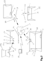
- FIG. 1 to 4 is a processing system 1 or processing unit 1 shown with a variety of components or structures.
- the processing system 1 Has a housing 2, in which the various components are integrated.
- the processing system 1 comprises At least one processing area 3, a control area 4, an input area 4a and optionally a receiving area 5 and / or presentation area 5.
- the individual arrangements of the components in the housing 2 is not limited to the presentation, but the components to others Positions in the housing 2 can be arranged.
- the housing 2 is preferably made of metal, in particular sheet metal, and has a plurality of doors, so that easy accessibility of the components arranged behind it is possible.
- a power supply unit 6 is arranged, from which the individual components can be supplied with energy.
- the power supply unit 6 is connected via a connecting cable (not shown) to a public power supply network (not shown).
- a public power supply network not shown.
- an emergency power system (not shown) is integrated, which is preferably activated automatically when the public power grid supplies no more energy. This ensures that, in the event of a power failure, the processing system 1 or at least the essential elements are still supplied with energy at least over a certain period of time, so that settings, machining operations or the like already made can be terminated and / or stored.
- the communication system 7 is used to output orders entered by a user and / or to have a visual printout of the input for inspection, ie that upon use of the processing system 1, a written confirmation or order can be issued which the user himself can use or the user can make a printout of his input created for preview in order to not be able to postpone it before it is implemented.
- a scanning device is arranged, via which, for example, the signed confirmation or the job can be scanned.
- the scanning device is used to scan, for example, graphics, layouts, images, company logos, which can be used for later processing.
- one or more additional modules with components integrated therein to be coupled to the housing 2 of the processing system 1.
- these are attached to the side walls of the housing 2.
- a subsequent extension of the processing system 1 is possible.
- a module may have as a component a scanner, which is set up, for example, on the module or is integrated in such a way that it can be easily operated by users from above by opening a cover.
- a module can be used as a warehouse for workpieces 9 or paper.
- a recycling system 8 is arranged in the housing 2 of the processing system 1.
- the recycling system 2 has a collecting container and a throw-in opening, through which residues of a machined workpiece 9 or blanks 9 can be inserted.
- a cleaning system 10 in particular an extraction system, integrated, which is activated on the one hand during a machining operation in the processing area 3 and on the other hand after a machining operation over a defined period of time for cleaning the workpiece 9.
- the cleaning system 10 is preferably designed such that during a machining process, the air sucks in the region of the workpiece to be machined 9, so that no odor nuisance for the user or operator arise when opening the processing room.
- the cleaning system 10 After completion of the machining process, the cleaning system 10 automatically switches, for example, via a valve flap (not shown) to the cleaning function for the user, so that the latter can now clean the workpiece 9 via a hose (not shown) with a suction brush fastened thereto and thus sucked off the dust particles can be. So that no odor nuisance occurs in the installation area, the cleaning system 10 is equipped with appropriate filters.
- Essential in such a processing system 1 is that several different workpieces 9 or blanks 9 can be processed or processed with a single device, the operation of the device or the processing system 1 has been simplified so that only an operator or a customer independently can work with the processing system 1. That means that for the local care no Skilled personnel for the processing device 1 is present, but only a trained operator, in particular seller of a department store.
- a detachable input device 11 or display element 11 of the input area 4a to which an operator software, also referred to below as "Trodesign", is installed, is arranged on the processing system 1.
- a corresponding with the operator software control software also referred to as "JobControl”, integrated, and that connected by connecting the display element 11 with the processing system 1 or by activation via a button 12 on the display element 11, the processing system 1 with this display element 11 is, that is, that the display element 11 is independent of the processing system 1, ie when removed display element 11, operated or operable so that you can work with the installed on the display element 11 operator software and only by deliberate coupling or connecting to the processing system 1 the Display element 11 is integrated into the processing system 1.
- the user has the ability to remove the display element 11 from the processing unit 1 and make his input in peace.
- the display element 11 may remain positioned on the processing system 1 and directly the input can be made.
- the so-called display element 11 serves as an input device, which preferably has a touch function, ie that an input to the display element 11 can be made by touching the surface. It is also possible that a plurality of display elements 11 can be used simultaneously, which are operated simultaneously by different users, since the display elements 11 can be operated independently of the processing unit 1.
- the contact device 13 for contacting, in particular for insertion, arranged.
- the contact device 13 is arranged on a sliding board 14, wherein the sliding board 14 is designed to cover the processing area 3, in particular for covering a portion of the processing area 3.
- the sliding board 14 may be equipped with corresponding sensors, so that activation of the processing system 1 is possible only by closing the sliding board 14, whereas it is interrupted during opening during a working process.
- the power supply in particular the charging of the display element 11 via the contact device 13 takes place.
- the activation of the processing system 1 is carried out by connecting the display element 11 to the contact device 13 or wirelessly by connecting via an operation of the corresponding hard- or software-executed button 12.
- the processing area 3 is formed by a laser plotter 15.
- the laser plotter 15 is for engraving, marking, cutting and manufacturing for different workpieces 9, in particular stamp plates blanks 9, signs, mobile phones, tablet computers, pens, sticks, computer accessories, such as cases, bags, etc., educated.
- the processing area 3 of the laser plotter 15 is designed such that in the processing area 3 of the laser plotter 15, a processing insert 15a, (schematically in FIG Fig. 3 indicated) is inserted or arranged.
- the processing insert 15a is formed such that a plurality of different workpieces 9 or blanks 9 can be positioned on a processing insert 15a, ie, for example, on a processing insert 15a a stamp plate blank 9, a shield (not shown) or an additional element for other workpieces 9, such as, for example, pens, sticks, etc., can be positioned so that the processing insert 15a need not be exchanged for these different workpieces 9.
- a processing insert 15a can be seen in detail from the concurrent Austrian priority application.
- the user creates a desired processing operation via the operator software, whereupon the processing operation is transferred to a control device, in particular to a control software, and is converted by this so that a Control of the processing device 1, in particular the Laserplotters 15, is carried out for performing the desired machining operation, whereupon the workpiece 9 in the processing apparatus 1, in particular on a processing insert 15a, positioned and the processing process can be started.
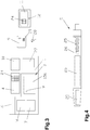
- connection system 16 for connecting the processing system 1, in particular the individual area, arranged with a parent network 17, in particular an Internet, the Connection system 16 for transmitting and receiving data 18 (shown schematically by an arrow) is formed, as shown schematically in FIG Fig. 2 is shown.
- the connection system 16 is designed for manual or automatic connection setup of the processing device 1 or processing system 1, or that from an external component 19, such as a computer, a connection via the connection system 16 is automatically activated or possible.
- the connection system 16 can also be integrated in the control unit 4 or the communication system 7.
- connection to the parent network 17 can be wirelessly via radio 20 or via a cable 21, in particular network or telephone cable or fiber optic cable, for example, a shop 22 or department store 22.
- a so-called Internet stick or data stick can be used.
- the connection system 16 interacts with the communication system 7, since the Internet stick can be simply plugged into the computer, in particular to a USB interface, of the communication system 7. If the processing system 1 is equipped with the connection system 16, then a separate identification number, in particular IP number, assigned, so that the processing unit 1 can be addressed directly.
- a plurality of processing systems 1, which are connected to one another via a cable 23, in particular a network cable 23, to be located in the shop 22 or large department store 22, wherein only a single processing system 1 is equipped with the connection system 16 the further processing system 1 can also be activated or controlled.
- the internal data exchange preferably takes place via the communication system 7 of each processing system 1.
- connection system 16 Through the use of the connection system 16 it is achieved that the processing system 1 can send data or receive external data. As a result, remote maintenance can also be carried out, for example, via the external component 19, since all data or systems can be accessed via the data connection. It is particularly advantageous that software updates are sent via the higher-level network, so that all processing systems 1 in use can be kept in a uniform state. Thus, software updates or malfunctions can be remedied very quickly by such updates.
- the processing system 1 is equipped with a database 24, ie that in the input area, in particular on the display element 11, and / or the control area 4, a database 24 is integrated, stored in the data of the workpieces to be processed 9 are, as shown schematically in Fig. 3 is shown.
- a database 24 is integrated, stored in the data of the workpieces to be processed 9 are, as shown schematically in Fig. 3 is shown.
- the data include, for example, the workpiece designation or type designation, a graphic image of the workpiece 9, the length, width and height of the workpiece 9, etc.
- processing areas 25 or engraving areas 25 are stored for the differently stored workpieces 9, so that the User can specifically activate the stored engraving 25 and can fill with appropriate texts or graphics, as in a workpiece 9 in the form of a pen 26 in Fig. 4 is shown.
- the novel processing systems 1 are equipped with such a database 24 for depositing workpieces 9, wherein for the workpieces 9 at least one processing region 25 is defined.
- a database 24 for depositing workpieces 9, wherein for the workpieces 9 at least one processing region 25 is defined.
- the workpiece 9 or type designation the graphical representation, the length, width and height of the workpiece 9, the material of the workpiece 9 or the material range at different Materials used, as well as at least one processing area 25, in particular an engraving area, as well as a start or zero point and / or reference point for the processing device 1, in particular the laser plotter 15, etc. deposited.
- the detection of the products, in particular of the workpieces 9, preferably takes place at the manufacturer or lessor of the processing system 1 itself, wherein the updating of the database 24 via the connection system 16 takes place, ie, if a user wants to edit a new product or workpiece 9 for the first time or if a new product or workpiece 9 comes on the market, this product is sent to the Monle or the manufacturer, who then recorded all data of the product and processed so that it can then be integrated into the database 24 and for the Selection is available. This is advantageous in that it must be ensured when first using a new product, which areas may be edited and which not.
- the input device or the display element 11b is equipped with a connection system 16, as shown schematically in FIG Fig. 2 is shown.
- a connection system 16 as shown schematically in FIG Fig. 2 is shown.
- the display element 11b can be spatially separated from the site of the processing unit 1 or processing system 1 can be used or used.
- Fig. 2 can thereby be operated in a shop 22a, a processing system 1 with an associated display element 11a, wherein in another, preferably adjacent store 22b, the display element 11b is operated or operable so that the customer in the shop 22b with the display element 11b create corresponding processing processes via the operator software.
- a job message is created and sent to an operator of the store 22a with the processing system 1.
- This order message for example, an activation of a beeper and / or SMS and / or email to a mobile phone, computer and / or activation of an information light on the processing system 1 done so that the operator can immediately recognize that an external processing has been received. It is also possible for all information to be contained and displayed in the order message, so that the operator can load the corresponding workpiece 9.
- a display element 11 in which a display element 11 is additionally operated in another store 22 or department store 22, it is preferred that the display element 11 is equipped with a connection system 16 for data exchange with a further connection system 16 in the processing system 1, the location-independent Display element 11 automatically suggests or selects the connection with the nearest processing system 1.
- a selection list of the obvious processing systems 1 can be retrieved or displayed, wherein the utilization or processing time for performing a processing process and / or the distance to the location of the display element 11 is shown.
- the customer can see how long it takes at which location, until his product is completed.
- the customer can select the processing system 1 which is best for him from the selection list so that the data is subsequently sent to him.
- a reading system 27 is integrated in the processing system 1 or on the display element 11.
- the reading system 27 is formed for example by a bar code scanner 28, a QR scanner, laser scanner, etc., or software technology by a corresponding app on the display element 11, wherein the scanner 28 is installed as a handheld device or in the housing 2 ,
- the user thus only needs to scan or record the code 29, in particular bar code or QR code, attached to the workpiece 9 or product with the reading system 27, in particular the scanner 28 or a camera on the display element 11 (not shown) , whereupon workpiece recognition takes place on the basis of the recognized code 29, since the code 29 is stored in the database 24 for the corresponding workpiece 9.
- the operator software then calls the corresponding product or workpiece 9 and is then updated with the data of the workpiece 9, so that the user only has to enter the texts or graphics in the processing areas 25. For this purpose, it is possible that a graphical representation of the product is displayed on the operator software, the deposited processing areas 25 are marked accordingly.
- the processing system 1 can also be designed in such a way that the control area 4 and / or input area 4a for automatic recognition of the workpiece 9 stored in the database 24 is formed by detecting the inserted workpiece 9. This can be done such that an automatic recognition of the workpiece 9 by detecting the length, the width and the height of the workpiece 9 takes place, so that due to the stored data for the workpiece 9, a corresponding evaluation is performed.
- the system is used in such a way that the Users in the operator software selects a product group, such as smartphone, tablet PC, smartphone cases, etc., so that due to the determination of the length, width and height of the workpiece 9 now due to the different dimensions of the manufacturer, the workpiece 9 or product and type is more easily recognizable or recognized and the data can be loaded, that is, by specifying a product group, the choice is reduced in the database, so that the most accurate detection of the product is possible.
- the detection can take place, for example, via a measurement in the processing area 3 or a scan of the product.
- a camera for receiving the processing area 9 or the workpiece 9 is arranged for automatic detection of the workpiece 9, ie that, for example, the inserted workpiece 9 from a processing area 3 associated camera (not shown) generates an image which then compared with the stored graphical images to the individual workpieces 9 and thus a corresponding evaluation is made.
- the display element 11 has a camera (not shown), with which the user takes an image of the product or workpiece 9 and this is then compared with the stored images.
- several images of the products, in particular all views, are preferably also stored in the database 24.
- the user or user is presented with a list of the most near or most loved products stored, so that he can subsequently select the corresponding product. It is also possible for the user to set the product or the workpiece 9 manually despite installed automatic recognition or without it, again preferably only those products of a product group being displayed to the user whom he selects, so that the selection of the products is simplified that is, the user first selects a product group, for example, smartphone, tablet PC, stamp, etc., on which only those products associated with those product groups are displayed. As a result, the number of products to be selected can be reduced user-friendly.
- the database 24 can be processed by the operator or seller in order to make a corresponding adjustment to the shop 22 or department store 22, in particular the product range.
- the operator or seller can call and activate or deactivate the individual workpieces 9, ie, the operator or seller adapts the workpieces 9 which can be called in the database 24 to the sales assortment of the shop 22, so that only those workpieces 9 can be called up, which are actually sold.
- this can also be done via the code 29 of the workpieces 9, for example, only the code 29 of the sales items, in particular the workpieces 9, is scanned so that subsequently only the scanned workpieces 9 are retrievable.
- a corresponding learning mode is activated, in which the sales range is entered.
- a newly acquired product in particular the data for this, to be uploaded by the manufacturer in a cloud 29, whereupon the individual processing system 1 independently updates the database 24 at defined times performs.
- updates to the operating system or other software updates or data may be stored in the cloud 29, which are automatically or manually retrieved by the processing systems 1.
- cloud storage 29 have the advantage that at any time data, software, etc. can be uploaded and they are available at any time. Thus, updates can be made in various continents of the world at those times when there is no operation of the store 22 or department store 22 so as not to disturb the operation of the facility.
- a warehouse management is integrated, so that the corresponding in the shop 22 to be purchased workpieces 9, in particular the stamp plate blanks 9 and / or the stamps for this or the accessories, etc., the inventory, ie the number of existing quantities of the product, is entered, which is reduced after a corresponding machining process for this product.
- a goods order is requested from processing system 1.
- processing system 1 directly via the connection system 16, a goods order to the manufacturer or supplier via the parent network 17, especially the Internet, be discontinued or the required goods order is displayed on the display element 11 or the processing system 1, so that the operator or seller activate this and can send.
- This warehouse management can in turn be activated or deactivated for the differently stored workpieces 9 in the database 24.
- any order addresses for the different workpieces 9 can be deposited.
Abstract
Die Erfindung beschreibt ein Bearbeitungssystem (1) umfassend zumindest einen Bearbeitungsbereich (3), einen Steuerbereich (4), einen Eingabebereich (4a), und optional einen Aufnahmebereich (5) und/oder einen Präsentationsbereich (5), wobei über ein Eingabe- und/oder Anzeigeelement (11) von einem User in einer darin installierten Bedienersoftware ein Text und/oder Grafik eingebbar ist, die an eine im Steuerbereich (4) laufende Steuersoftware übergebbar ist, wobei ein Lesesystem zum Erfassen eines Code (29) angeordnet ist. Am Anzeigeelement (11) ist das Lesesystem (27) integriert, wobei das Lesesystem (27) zum Erfassen des Werkstückes (9) über einen am Werkstück (9) angebrachten Code (29) integriert ist, und dass die für dieses Werkstück (9) hinterlegten Daten von einer Bedienersoftware an einem Eingabegerät (11) bzw. Anzeigeelement (11) abrufbar sind.The invention describes a processing system (1) comprising at least one processing area (3), a control area (4), an input area (4a), and optionally a receiving area (5) and / or a presentation area (5), wherein an input and / or display element (11) by a user in an installed therein user software, a text and / or graphics can be entered, which can be passed to a control area (4) running control software, wherein a reading system for detecting a code (29) is arranged. On the display element (11), the reading system (27) is integrated, wherein the reading system (27) for detecting the workpiece (9) via a workpiece (9) attached code (29) is integrated, and that for this workpiece (9) stored data from an operator software on an input device (11) or display element (11) are retrievable.
Description
Die Erfindung betrifft ein Bearbeitungssystem, wie es in dem Oberbegriff des Anspruches 1 beschrieben ist.The invention relates to a processing system, as described in the preamble of
Aus der
Weiters ist aus der
Bei der
Darüber hinaus ist auch ein System aus der
Aus dem Stand der Technik sind System bekannt, bei denen von speziell geschultem Fachpersonal, sogenannten Stempelmachern, Stempelplatten bzw. Textplatten für Stempel, insbesondere Handstempel, erstellt werden. Dazu wird von dem Fachpersonal an einem Computer unter zu Hilfenahme von standardisierter Software, insbesondere Corel-Draw, Word, usw., ein Stempelabdruck durch Grafiken und/oder Texte entsprechend den Wünschen des Kunden erstellt. Daraufhin werden die Daten an ein Bearbeitungsgerät, insbesondere einen Laserplotter, oder eine Steuerung hierfür übertragen, worauf eine Konvertierung der Daten bevorzugt unter zu Hilfenahme von hinterlegten Daten u/o Tabellen erfolgt. Anschließend legt das Fachpersonal ein Werkstück, insbesondere einen sogenannten Rohling, der aus einem flexiblen Gummi gebildet ist, in die Bearbeitungsvorrichtung, worauf eine manuelle und oder automatische Positionierung des Bearbeitungsgerätes, insbesondere einer Strahlquelle eines Lasers, erfolgt. Das Fachpersonal startet daraufhin den Bearbeitungsvorgang, sodass ein Negativabdruck des vom Fachpersonal am Computer erstellten Stempelabdrucks am Rohling erzeugt wird. Nachdem der Bearbeitungsvorgang beendet ist, entnimmt das Fachpersonal den Rohling und reinigt diesen von den Bearbeitungsrückständen. Anschließend wird der negative Stempelabdruck auf den Druckplattenträger, an dem bereits eine Klebeschicht angeordnet ist, aufgeklebt. Nachteilig ist hierbei, dass bei einem derartigen Vorgehen der Kunde den Stempel nicht direkt mitnehmen kann, sondern diesen erst später abholen kann bzw. ihm zugeschickt wird. Darüber hinaus kann der Kunde auch keinen Einfluss bei der Erstellung des Stempelabdruckes nehmen, da dieser vom Fachpersonal erstellt wird und nicht direkt vom Kunden.Systems are known from the prior art, in which by specially trained personnel, so-called stamp makers, stamp plates or text plates for stamps, especially hand stamps created. For this purpose, the specialist personnel on a computer with the help of standardized software, especially Corel Draw, Word, etc., creates a stamp imprint by graphics and / or text according to the wishes of the customer. Subsequently, the data is transmitted to a processing device, in particular a laser plotter, or a controller for this purpose, whereupon a conversion of the data preferably takes place with the aid of stored data and / or tables. Subsequently, the skilled person places a workpiece, in particular a so-called blank, which is formed from a flexible rubber, into the processing device, whereupon a manual and or automatic positioning of the processing device, in particular a beam source of a laser, takes place. The specialist personnel then starts the machining process so that a negative impression of the stamp imprint created by the specialist on the computer is generated on the blank. After the machining process is completed, the specialist takes the blank and cleans it of the processing residues. Subsequently, the negative stamp imprint on the printing plate support, on the already an adhesive layer is arranged, glued. The disadvantage here is that in such a procedure, the customer can not take the stamp directly, but this can pick up later or is sent to him. In addition, the customer can also take no influence in the creation of the stamp, as this is created by professionals and not directly from the customer.
Aus der
Weiters ist aus dem Stand der Technik, insbesondere aus der
Aus der
Nachteilig ist bei derartigen Systemen, dass mit dem Bearbeitungsgerät nur eine Aufgabe, nämliche die des Erzeugens einer photopolymeren Stempelplatte, durchgeführt werden kann.A disadvantage of such systems is that only one task, namely the production of a photopolymer stamp plate, can be carried out with the processing device.
Die Aufgabe der Erfindung liegt darin, ein Bearbeitungssystem, sowie ein Verfahren zu schaffen, bei dem die Bedienerfreundlichkeit wesentlich erhöht wird. Gleichzeitig soll der Wartungsaufwand für die Anlagen bzw. System so gering als möglich gehalten werden. Eine weitere Aufgabe liegt darin, die Nachteile des Standes der Technik möglichst zu beheben.The object of the invention is to provide a processing system and a method in which the user-friendliness is substantially increased. At the same time the maintenance of the systems or system should be kept as low as possible. Another object is to remedy the disadvantages of the prior art as possible.
Die Erfindung wird durch ein Bearbeitungssystem gelöst, bei dem am Anzeigeelement 11 das Lesesystem (27) integriert ist, wobei das Lesesystem (27) zum Erfassen des Werkstückes (9) über einen am Werkstück (9) angebrachten Code (29) integriert ist, und dass die für dieses Werkstück (9) hinterlegten Daten von einer Bedienersoftware an einem Eingabegerät (11) bzw. Anzeigeelement (11) abrufbar sind.The invention is achieved by a processing system in which on the
Vorteilhaft ist hierbei, dass dadurch die Fehleingaben bei der Produktauswahl verhindert wird, da für jedes Produkt ein eindeutiger einzigartiger Code vergeben wird. Gleichzeitig kann dieser Code auch für weitere Informationen und System, insbesondere der Preisverwaltung, der Lagerverwaltung, usw., verwendet werden, sodass der Code entsprechend übergeben wird. Dadurch ist auch eine vereinfachte Verwaltung möglich. Der wesentlich Vorteil liegt jedoch darin, dass mit einer derartigen Ausstattung des Bearbeitungssystem der User keinerlei Eingaben in Bezug auf das Produkt vornehmen muss, sondern lediglich den Code mit einem entsprechenden Gerät scannen muss, worauf sämtlich benötigten Daten automatisch geladen werden.It is advantageous hereby that the incorrect entries in the product selection is prevented because a unique unique code is assigned for each product. At the same time, this code can also be used for other information and system, in particular price management, warehouse management, etc., so that the code is passed accordingly. As a result, a simplified administration is possible. The main advantage, however, lies in the fact that with such a configuration of the processing system, the user does not have to make any input with regard to the product, but merely has to scan the code with a corresponding device, whereupon all the required data is automatically loaded.
Es ist auch von Vorteil, wenn der Code durch einen Bar-Code bzw. Strich-Code oder einem QR-Code gebildet ist, da dadurch handelsübliche System, die auch von anderen Anwendungen, wie einer Lagerverwaltung, dem Verrechnungssystem, usw., genützt werden. Somit ist es lediglich notwendig einen einzigen Code am Produkt anzuordnen bzw. aufzukleben, der anschließend im gesamten Geschäft bzw. Kaufhaus für alle Systeme genützt werden kann.It is also advantageous if the code is formed by a bar code or a QR code, as this commercial system, which are also used by other applications, such as a warehouse, the billing system, etc., are used , Thus, it is only necessary to arrange or stick a single code on the product, which can then be used in the entire store or department store for all systems.
Es ist auch eine Ausgestaltung von Vorteil, bei der die Erfassung des Codes über einen Scanner oder über eine Kamera am Eingabe- bzw. Anzeigeelement beispielsweise durch eine darauf installierte App erfolgt bzw. durchführbar ist, da dadurch handelsübliche Geräte bzw. System eingesetzt werden können, wodurch die Kosten reduziert werden können. Durch eine derartige Integration eines aus dem Stand der Technik bekanntes System ist auch eine Verwendung eines Codes für andere Anlagen möglich.It is also an embodiment of advantage in which the detection of the code via a scanner or a camera on the input or display element, for example by an installed on it App is or is feasible, as this commercially available devices or system can be used, whereby the cost can be reduced. Such an integration of a system known from the prior art also makes it possible to use a code for other systems.
Die Erfindung wird anschließend in Form von Ausführungsbeispielen beschrieben, wobei darauf hingewiesen wird, dass die Erfindung nicht auf die dargestellten und beschriebenen Ausführungsbeispiele bzw. Lösungen begrenzt ist.The invention will now be described in the form of embodiments, it being understood that the invention is not limited to the illustrated and described embodiments or solutions.
Es zeigen:
- Fig.1
- ein Übersichtschaubild eines Bearbeitungssystems zur Bearbeitung von Werkstücken und Erzeugung von Textplatten für Stempel;
- Fig.2
- eine schaubildliche Darstellung mehrerer Bearbeitungssystem an unterschiedlichen Aufstellungsorten;
- Fig.3
- eine schematische Darstellung eines Bearbeitungssystem mit zusätzlichen Komponenten, insbesondere zum Erfassen eines Werkstücks;
- Fig.4
- ein Werkstück in vereinfachter, schematischer Darstellung mit unterschiedlichen Bearbeitungsbereichen.
- Fig.1
- an overview diagram of a processing system for machining workpieces and generating text plates for stamps;
- Fig.2
- a perspective view of several processing system at different sites;
- Figure 3
- a schematic representation of a processing system with additional components, in particular for detecting a workpiece;
- Figure 4
- a workpiece in a simplified, schematic representation with different processing areas.
Einführend sei festgehalten, dass in den unterschiedlichen Ausführungsformen gleiche Teile mit gleichen Bezugszeichen bzw. gleichen Bauteilbezeichnungen versehen werden, wobei die in der gesamten Beschreibung enthaltenen Offenbarungen sinngemäß auf gleiche Teile mit gleichen Bezugszeichen bzw. gleichen Bauteilbezeichnungen übertragen werden können. Auch sind die in der Beschreibung gewählten Lageangaben, wie z.B. oben, unten, seitlich usw. auf die beschriebene Figur bezogen und sind bei einer Lageänderung sinngemäß auf die neue Lage zu übertragen. Auch können Einzelmerkmale oder Merkmalskombinationen aus den gezeigten und beschriebenen Ausführungsbeispielen für sich eigenständige erfinderische Lösungen darstellen.By way of introduction, it should be noted that in the various embodiments, the same parts are provided with the same reference numerals or the same component names, wherein the disclosures contained in the entire description can be mutatis mutandis to the same parts with the same reference numerals and component names. Also, the location information chosen in the description, such as top, bottom, side, etc. related to the described figure and are mutatis mutandis transferred to the new situation in a change in position. Also, individual features or combinations of features from the illustrated and described embodiments may represent separate inventive solutions.
In den
Das Bearbeitungssystem 1, gemäß
Das Gehäuse 2 ist bevorzugt aus Metall, insbesondere Blech, gebildet und weist mehrere Türen auf, sodass eine einfache Zugänglichkeit der dahinter angeordneten Komponenten möglich ist. Bevorzugt ist im hinteren Bereich, insbesondere auf der Rückseite, eine Stromversorgungseinheit 6 angeordnet, von der aus die einzelnen Komponenten mit Energie versorgt werden können. Die Stromversorgungseinheit 6 wird über ein Anschlusskabel (nicht dargestellt) mit einem öffentlichen Stromversorgungsnetz (nicht dargestellt) verbunden. Es ist auch möglich, dass in der Stromversorgungseinheit 6 ein Notstromsystem (nicht dargestellt) integriert ist, welches bevorzugt automatisch aktiviert ist, wenn das öffentliche Stromversorgungsnetz keine Energie mehr liefert. Somit ist sichergestellt, dass bei einem Stromausfall zumindest über eine gewisse Zeitdauer das Bearbeitungssystem 1 oder zumindest die wesentlichen Elemente noch mit Energie versorgt werden, sodass bereits vorgenommene Einstellungen, Bearbeitungsvorgänge oder dgl., beendet und/oder gespeichert werden können.The
Weiters ist im Gehäuse 2 ein Kommunikationssystem 7, insbesondere ein Computer mit einem Drucker, angeordnet. Das Kommunikationssystem 7 dient dazu, um von einem Nutzer eingegebenen Aufträge auszugeben und/oder einen optischen Ausdruck der Eingabe zur Kontrolle zu haben, d.h., dass bei einer Nutzung des Bearbeitungssystem 1 eine schriftliches Bestätigung bzw. Auftrag ausgegeben werden kann, die der Nutzer für sich verwenden kann oder das der Nutzer sich einen Ausdruck seiner erstellten Eingabe zur Voransicht machen kann, um diesen bei nicht gefallen noch nachbearbeiten zu können, bevor dieser umgesetzt wird. Dabei ist es auch möglich, dass im Kommunikationssystem 7 auch ein Scan-Gerät angeordnet ist, über das beispielsweise die abgezeichnete Bestätigung oder der Auftrag eingescannt werden kann. Bevorzugt wird das Scan-Gerät jedoch dazu verwendet, um beispielsweise Graphiken, Layouts, Bilder, Firmenlogos einzuscannen, welche für die spätere Bearbeitung verwendet werden können.Furthermore, a
Auch ist es möglich, dass ein oder mehrere zusätzliches Module (nicht dargestellt) mit darin integrierten Komponenten an das Gehäuse 2 des Bearbeitungssystems 1 zu koppeln. Bevorzugt werden diese an den Seitenwänden des Gehäuses 2 angebracht. Dadurch ist eine nachträgliche Erweiterung des Bearbeitungssystem 1 möglich. Beispielsweise kann ein derartiges Modul als Komponente einen Scanner aufweisen, der beispielsweise auf das Modul aufgestellt ist oder derart integriert ist, dass dieser von Nutzer von oben einfach bedient werden kann, in dem dieser eine Abdeckung bzw. Deckel öffnet. Auch ist es möglich, dass ein derartiges Modul als Lager für Werkstücke 9 oder Papier genützt werden kann.It is also possible for one or more additional modules (not shown) with components integrated therein to be coupled to the
Es ist auch möglich, dass ein Recyclingsystem 8 im Gehäuse 2 des Bearbeitungssystem 1 angeordnet ist. Das Recyclingsystem 2 weist einen Auffangbehälter und eine Einwurföffnung auf, durch die Reste eines bearbeiteten Werkstückes 9 bzw. Rohlings 9 eingeworfen werden können.It is also possible that a
Weiters ist im Bearbeitungssystem 1 ein Reinigungssystem 10, insbesondere eine Absauganlage, integriert, die einerseits während eines Bearbeitungsvorganges im Bearbeitungsbereich 3 und andererseits nach einem Bearbeitungsvorganges über eine definierte Zeitdauer zum Reinigen des Werkstückes 9 aktiviert ist. Das Reinigungssystem 10 ist bevorzugt derart ausgebildet, dass während eines Bearbeitungsvorganges die Luft im Bereich des zu bearbeitenden Werkstückes 9 absaugt, sodass beim Öffnen des Bearbeitungsraumes keine Geruchsbelästigungen für den User bzw. Operator entstehen. Nach Beendigung des Bearbeitungsvorganges wird vom Reinigungssystem 10 automatisch beispielsweise über eine Ventilklappe (nicht dargestellt) auf die Reinigungsfunktion für den Nutzer umgeschaltet, sodass dieser nunmehr über einen Schlauch (nicht dargestellt) mit einer daran befestigten Saugbürste das Werkstück 9 reinigen kann und somit die Staubpartikel abgesaugt werden können. Damit im Aufstellungsbereich keinerlei Geruchsbelästigungen auftreten, ist das Reinigungssystem 10 mit entsprechenden Filtern ausgestattet.Furthermore, in the
Wesentlich bei einem derartige Bearbeitungssystem 1 ist, dass mehrere unterschiedliche Werkstücke 9 bzw. Rohlinge 9 mit einem einzigen Gerät verarbeitet bzw. bearbeitet werden können, wobei die Bedienung des Gerätes bzw. des Bearbeitungssystem 1 derart vereinfacht wurde, dass lediglich ein Operator oder ein Kunde selbstständig mit dem Bearbeitungssystem 1 arbeiten kann. D.h., dass für die Vor Ortbetreuung keinerlei Fachpersonal für das Bearbeitungsgerät 1 vorhanden ist, sondern lediglich ein geschulter Operator, insbesondere Verkäufer eines Kaufhauses. Für die einfache Bedienung ist am Bearbeitungssystem 1 ein abnehmbares Eingabegerät 11 bzw. Anzeigeelement 11 des Eingabebereiches 4a, an der eine Bedienersoftware, im Folgenden auch "Trodesign" genannt, installiert ist, angeordnet. Im Steuerbereich 4 ist eine mit der Bedienersoftware korrespondierende Steuersoftware, im Folgenden auch "JobControl" genannt, integriert, und dass durch Verbinden des Anzeigeelementes 11 mit dem Bearbeitungssystem 1 oder durch Aktivierung über einen Button 12 am Anzeigeelement 11 das Bearbeitungssystem 1 mit diesem Anzeigeelement 11 verbunden ist, d.h., dass das Anzeigeelement 11 unabhängig vom Bearbeitungssystem 1, also bei abgenommen Anzeigeelement 11, betrieben wird bzw. betreibbar ist, sodass mit der am Anzeigeelement 11 installierten Bedienersoftware gearbeitet werden kann und erst durch bewusstes Koppeln bzw. Verbinden mit dem Bearbeitungssystem 1 das Anzeigeelement 11 in das Bearbeitungssystem 1 integriert ist. Durch eine derartige Ausbildung hat der Nutzer die Möglichkeit das Anzeigeelement 11 vom Bearbeitungsgerät 1 abzunehmen und in Ruhe seine Eingabe vorzunehmen. Selbstverständlich ist es möglich, dass das Anzeigeelement 11 auch am Bearbeitungssystem 1 positioniert bleiben kann und direkt die Eingabe vorgenommen werden können. Das sogenannte Anzeigeelement 11 dient als Eingabegerät, welches bevorzugt eine Touchfunktion aufweist, d.h., dass durch Berühren der Oberfläche eine Eingabe am Anzeigeelemente 11 vorgenommen werden kann. Auch ist es möglich, dass mehrere Anzeigeelemente 11 gleichzeitig eingesetzt werden können, die gleichzeitig von unterschiedlichen Usern bedient werden, da die Anzeigeelemente 11 unabhängig vom Bearbeitungsgerät 1 betrieben werden können.Essential in such a
Für das Anzeigeelement 11 ist eine Kontaktvorrichtung 13 zum Kontaktieren, insbesondere zum Hineinstecken, angeordnet. Bevorzugt ist die Kontaktvorrichtung 13 auf einem Slidingboard 14 angeordnet, wobei das Slidingboard 14 zum Abdecken des Bearbeitungsbereichs 3, insbesondere zum Abdecken eines Teilbereichs des Bearbeitungsbereichs 3, ausgebildet ist. Als Sicherheitsfunktion kann das Slidingboard 14 mit entsprechenden Sensoren ausgestattet sein, sodass erst durch Schließen des Slidingboards 14 eine Aktivierung des Bearbeitungssystem 1 möglich ist, wogegen beim Öffnen während eines Arbeitsprozesses dieser unterbrochen wird. Selbstverständlich ist es möglich, dass die Stromversorgung, insbesondere das Aufladen des Anzeigeelementes 11 über die Kontaktvorrichtung 13 erfolgt.For the
Bevorzugt erfolgt die Aktivierung des Bearbeitungssystem 1 durch Verbinden des Anzeigeelementes 11 mit der Kontaktvorrichtung 13 oder drahtlos durch Verbinden über eine Betätigung des entsprechen hard- oder softwaremäßigen ausgeführten Button 12. Durch das Verbinden wird beispielsweise eine Datenübertragung von der Bedienersoftware zur Steuersoftware ausgelöst, sodass eine Verarbeitung der Daten möglich ist. Hierzu ist der Bearbeitungsbereich 3 durch einen Laserplotter 15 gebildet. Der Laserplotter 15 ist zum Gravieren, Markieren, Schneiden und Herstellen für unterschiedliche Werkstücke 9, insbesondere vom Stempelplatten bzw. Stempelplatten-Rohlingen 9, Schilder, Handys, Tablet-Computer, Kugelschreiber, Sticks, Computerzubehör, wie beispielsweise Hüllen, Taschen, usw., ausgebildet. Es kann ein ein- oder mehrstrahliger Laserplotter 15 verwendet werden, wobei bei einem Einsatz eines mehrstrahligen Laserplotters 15 für die unterschiedlichen Materialien die unterschiedlichen Laser verwendet werden können, d.h., dass beispielsweise vom Operator bzw. User in der Bedienersoftware bereits das zu bearbeitende Material ausgewählt wird, sodass anschließend von der Steuersoftware die entsprechende Laserquelle bzw. Laser aktiviert wird.Preferably, the activation of the
Um eine weitere bedienerfreundliche Ausstattung des Bearbeitungssystem 1 zu erreichen, ist der Bearbeitungsbereich 3 des Laserplotters 15 derart ausgebildet, dass in den Bearbeitungsbereich 3 des Laserplotters 15 eine Bearbeitungseinlage 15a, (schematisch in
Grundsätzlich kann gesagt werden , dass an dem Eingabegerät 11, insbesondere dem Anzeigeelement 11, vom Nutzer ein gewünschter Bearbeitungsvorgang über die Bedienersoftware erstellt wird, worauf der Bearbeitungsvorgang an ein Steuergerät, insbesondere an eine Steuersoftware, übergeben wird und von diesem derart umgewandelt wird, dass eine Ansteuerung des Bearbeitungsgeräts 1, insbesondere des Laserplotters 15, zum Durchführen des gewünschten Bearbeitungsvorgang durchgeführt wird, worauf das Werkstück 9 in das Bearbeitungsgerät 1, insbesondere auf einer Bearbeitungseinlage 15a, positioniert wird und der Bearbeitungsprozess gestartet werden kann.Basically, it can be said that on the
Damit das Stand-Alone-Gerät einfach betrieben werden kann, ist im Bearbeitungssystem 1, insbesondere im Gehäuse 2, ein Verbindungssystem 16 zum Verbinden des Bearbeitungssystem 1, insbesondere der einzelnen Bereich, mit einem übergeordneten Netzwerks 17, insbesondere einem Internet, angeordnet, wobei das Verbindungssystem 16 zum Senden und Empfangen von Daten 18 (schematisch durch einen Pfeil dargestellt) ausgebildet ist, wie dies schematisch in
Die Verbindung mit dem übergeordneten Netzwerk 17 kann kabellos per Funk 20 oder über ein Kabel 21, insbesondere Netzwerk- oder Telefonkabel oder Glasfaserkabel, beispielsweise eines Geschäftes 22 bzw. Kaufhauses 22 erfolgen. Insbesondere ist es möglich, das ein sogenannter Internet-Stick bzw. Daten-Stick einsetzbar ist. Hierzu ist es von Vorteil, wenn das Verbindungssystem 16 mit dem Kommunikationssystem 7 zusammen wirkt, da der Internet-Stick an dem Computer, insbesondere an eine USB-Schnittstelle, des Kommunikationssystems 7 einfach angesteckt werden kann. Wird das Bearbeitungssystem 1 mit dem Verbindungssystem 16 ausgestattet, so wird eine eigene Identifikationsnummer, insbesondere IP-Nummer, vergeben, sodass das Bearbeitungsgerät 1 direkt angesprochen werden kann. Auch ist es möglich, dass in dem Geschäft 22 bzw. Großkaufhause 22 mehrere Bearbeitungssystem 1 aufgestellt sind, die über ein Kabel 23, insbesondere ein Netzwerkkabel 23, miteinander verbunden sind, wobei nur ein einziges Bearbeitungssystem 1 mit dem Verbindungssystem 16 ausgestattet ist, über den die weiteren Bearbeitungssystem 1 ebenfalls aktivierbar bzw. ansteuerbar sind. Bevorzugt erfolgt der interne Datenaustausch über das Kommunikationssystem 7 jedes Bearbeitungssystems 1.The connection to the
Durch den Einsatz des Verbindungssystem 16 wird erreicht, dass das Bearbeitungssystem 1 Daten abschicken kann oder externe Daten empfangen kann. Dadurch kann auch eine Fernwartung beispielsweise über die externe Komponente 19 durchgeführt werden, da über die Datenverbindung auf sämtliche Daten bzw. Systeme zugegriffen werden kann. Besonders von Vorteil ist, dass über das übergeordnete Netzwerk 17 Software-Updates versendet werden, sodass sämtliche im Einsatz befindlichen Bearbeitungssystem 1 auf einem einheitlichen Stand gehalten werden können. Somit können durch derartige Updates Softwarefehler oder Fehlfunktionen sehr rasch behoben werden.Through the use of the
Darüber hinaus ist es möglich, dass das Bearbeitungssystem 1 mit einer Datenbank 24 ausgestattet ist, d.h., dass in dem Eingabebereich, insbesondere am Anzeigeelement 11, und/oder dem Steuerbereich 4 eine Datenbank 24 integriert ist, in der Daten der zu bearbeitenden Werkstücke 9 hinterlegt sind, wie dies schematisch in
Die Erfassung der Produkte, insbesondere der Werkstücke 9, erfolgt bevorzugt beim Hersteller bzw. Vermieter des Bearbeitungssystem 1 selbst, wobei die Aktualisierung der Datenbank 24 über das Verbindungssystem 16 erfolgt, d.h., wenn ein User ein neues Produkt bzw. Werkstück 9 erstmalig bearbeiten möchte oder wenn ein neues Produkt bzw. Werkstück 9 auf den Markt kommt, so wird dieses Produkt an die Zentralle bzw. dem Hersteller gesendet, der anschließend sämtliche Daten des Produktes erfasst und derart aufbereitete, das diese anschließend in die Datenbank 24 integriert werden kann und für die Auswahl zur Verfügung steht. Dies ist insofern von Vorteil, da bei der erstmaligen Nutzung eines neuen Produktes sichergestellt werden muss, welche Bereiche bearbeitet werden dürfen und welche nicht.The detection of the products, in particular of the
Grundsätzlich wäre es jedoch möglich, durch entsprechende Eingabe neuartige Produkte direkt Vor Ort einzugeben und zu speichern, sodass diese später wieder zur Verfügung stehen. Auch wäre es denkbar, dass nach der Speicherung die Daten an den Hersteller bzw. die Zentralle zur Kontrolle und Überarbeitung übermittelt wird, sodass diese anschließend das Produkt auch für andere Bearbeitungssysteme 1 in anderen Geschäften 22 freigibt und diese Daten über deren Verbindungssysteme 16 aktualisiert werden. Bei einem derartigen Vorgehen ist es von Vorteil, dass eine unmittelbare Bearbeitung des neuen Produktes vom User Vor Ort durchgeführt werden kann, sodass dieser nicht darauf warten muss, bis die Daten in die Datenbank 24 eingespielt werden, wobei jedoch anschließend eine detaillierte Überarbeitung und Erfassung der gespeicherten Daten des Produktes vom Hersteller oder Vermieter vorgenommen wird.In principle, however, it would be possible to input and store new products locally by entering them, so that they are available again later. It would also be conceivable for the data to be sent to the manufacturer or the central office for checking and revision after the storage, so that the latter then also releases the product for
Weiters ist es möglich, dass das Eingabegerät bzw. das Anzeigeelement 11b mit einem Verbindungssystem 16 ausgestattet ist, wie dies schematisch in
Bevorzugt wird bei einem derartigen Ausbildung, bei dem ein Anzeigeelement 11 in einem anderen Geschäft 22 bzw. Kaufhaus 22 zusätzlich betrieben wird, dass das Anzeigeelement 11 mit einem Verbindungssystem 16 zum Datenaustausch mit einem weiterem Verbindungssystem 16 in dem Bearbeitungssystem 1 ausgestattet ist, wobei das ortsunabhängige Anzeigeelement 11 automatisch die Verbindung mit dem am nächst gelegenen Bearbeitungssystem 1 vorschlägt bzw. auswählt. Dabei ist in der Bedienersoftware eine Auswahlliste der naheliegenden Bearbeitungssysteme 1 abrufbar bzw. dargestellt, wobei die Auslastung bzw. Bearbeitungszeit zum Durchführen eines Bearbeitungsprozesses und/oder die Entfernung zum Standort des Anzeigeelementes 11 dargestellt ist. Somit kann der Kunde sehen, wie lange es an welchen Standort dauert, bis sein Produkt fertig gestellt ist. Der Kunde kann aus der Auswahlliste das für ihm Best mögliche Bearbeitungssystem 1 auswählen, sodass anschließend an dieses die Daten übersendet werden. Weiters ist es möglich, dass zusätzlich zur Anzeige der Entfernung zum Standort des Anzeigeelementes 11 und der Bearbeitungszeit bzw. Auslastung eine Wegbeschreibung zum aus der Auswahlliste ausgewählten Bearbeitungssystem 1 angezeigt und über das Kommunikationssystem 7 ausdruckbar ist.In such an embodiment, in which a
Zur Vereinfachung der Auswahl des zu bearbeitenden Produktes bzw. Werkstückes 9 ist es auch möglich, dass ein Lesesystem 27 in das Bearbeitungssystem 1 oder am Anzeigeelement 11 integriert ist. Das Lesesystem 27 ist beispielsweise durch einen Bar-Code-Scanner 28, einen QR-Scanner, Laser-Scanner, usw., oder Softwaretechnisch durch einen entsprechende App am Anzeigeelement 11 gebildet, wobei der Scanner 28 als Handgerät oder in das Gehäuse 2 eingebaut ist. Der User braucht somit nur noch dem am Werkstück 9 bzw. Produkt angebrachten Code 29, insbesondere Bar-Code oder QR-Code, mit dem Lesesystem 27, insbesondere den Scanner 28 oder einer Kamera am Anzeigeelement 11 (nicht dargestellt), einzuscannen bzw. aufzunehmen, worauf aufgrund des erkannten Codes 29 ein Werkstückerkennung erfolgt, da der Code 29 zu dem entsprechenden Werkstück 9 in der Datenbank 24 hinterlegt ist. Die Bedienersoftware ruft anschließend das entsprechende Produkt bzw. Werkstück 9 auf und wird anschließend mit den Daten des Werkstückes 9 aktualisiert, sodass der User nur noch die Texte bzw. Graphiken in den Bearbeitungsbereichen 25 eingeben muss. Hierzu ist es möglich, dass eine graphische Darstellung des Produktes an der Bedienersoftware dargestellt wird, wobei die hinterlegten Bearbeitungsbereiche 25 entsprechend markiert sind.To simplify the selection of the product or
Das Bearbeitungssystem 1 kann jedoch auch derart ausgeführt sein, dass der Steuerbereich 4 und/oder Eingabebereich 4a zur automatischen Erkennung des in der Datenbank 24 hinterlegten Werkstückes 9 durch Erfassen des eingelegten Werkstückes 9 ausgebildet ist. Dies kann derart erfolgen, dass eine automatische Erkennen des Werkstückes 9 durch die Erfassung der Länge, der Breite und der Höhe des Werkstückes 9 erfolgt, sodass aufgrund der hinterlegten Daten für das Werkstück 9 eine entsprechende Auswertung durchgeführt wird. Bevorzugt wird das System derart eingesetzt, in dem der User in der Bedienersoftware eine Produktgruppe, wie beispielsweise Smartphone, Tablet-PC, Smartphone-Hüllen, usw. auswählt, sodass aufgrund der Ermittlung der Länge, Breite und Höhe des Werkstückes 9 nunmehr auf Grund der unterschiedlichen Dimensionen der Hersteller das Werkstück 9 bzw. Produkt und Type einfacher erkennbar ist bzw. erkannt wird und die Daten geladen werden können, d.h., dass durch die Vorgabe einer Produktgruppe die Auswahlmöglichkeit in der Datenbank reduziert wird, sodass eine möglichst exakte Erkennung des Produktes möglich ist. Die Erfassung kann beispielsweise über ein Vermessung im Bearbeitungsbereich 3 oder einen Scann des Produktes erfolgen.However, the
Auch ist es möglich, dass zum automatischen Erkennen des Werkstückes 9 eine Kamera zur Aufnahme des Bearbeitungsbereiches 9 oder des Werkstückes 9 angerordnet ist, d.h., dass beispielsweise das eingelegte Werkstück 9 von einer dem Bearbeitungsbereich 3 zugeordneten Kamera (nicht dargestellt) eine Abbildung erzeugt, welches dann mit dem hinterlegten graphischen Bildern zu den einzelnen Werkstücken 9 verglichen wird und somit eine entsprechende Auswertung vorgenommen wird. Eine weitere Möglichkeit ist, dass das Anzeigeelement 11 eine Kamera (nicht dargestellt) aufweist, mit der der User ein Bild des Produktes bzw. Werkstückes 9 aufnimmt und dieses anschließend mit den hinterlegten Bildern verglichen wird. Bevorzugt sind dazu auch mehrere Bilder der Produkte, insbesondere sämtliche Ansichten, in der Datenbank 24 hinterlegt.It is also possible that a camera for receiving the
Sollte bei der automatischen Erkennung des Werkstückes 9 bzw. der Type des Produkts keine eindeutige Zuordnung vom Produkten möglich sein, so wird dem Nutzer bzw. User eine Auflistung der nahe liebendsten bzw. möglichsten hinterlegten Produkte angezeigt, sodass dieser anschließend das entsprechende Produkt auswählen kann. Auch ist es möglich, dass der User trotz installierter automatischen Erkennung oder ohne dieser das Produkt bzw. das Werkstück 9 manuell einstellt, wobei wiederum bevorzugt dazu immer nur jene Produkte einer Produktgruppe den User angezeigt werden, die er auswählt, sodass die Auswahl der Produkte vereinfacht wird, d.h., dass der User zuerst eine Produktgruppe, beispielsweise Smartphone, Tablet-PC, Stempel, usw., auswählt, worauf nur jene Produkte angezeigt werden, die diesen Produktgruppen zugeordnet sind. Dadurch kann die Anzahl der auszuwählende Produkte bedienerfreundlich reduziert werden. Hierzu ist es auch möglich, dass mehrere derartige Abstufungen von Gruppen möglich sind, um die Anzahl der Produkte so weit wie möglich zu verringern und somit die Bedienerfreundlichkeit zu erhöhen. Diese Gruppen sind zu den Produkten in der Datenbank 24 gespeichert, wobei es möglich ist, dass mehrere Gruppendefinitionen für ein Produkt gespeichert werden können, sodass dieses Produkt bei unterschiedlichen Gruppen auf der Auswahlliste angezeigt wird.If, in the case of automatic recognition of the
Weiters ist es möglich, dass die Datenbank 24 vom Operator bzw. Verkäufer bearbeitet wird, um eine entsprechend für das Geschäft 22 bzw. Kaufhaus 22, insbesondere dem Produktsortiment, Anpassung vorzunehmen. Dazu kann der Operator bzw. Verkäufer die einzelnen Werkstücke 9 aufrufen und aktivieren bzw. deaktivieren, d.h., dass der Operator bzw. Verkäufer die in der Datenbank 24 aufrufbaren Werkstücke 9 an das Verkaufssortiment des Geschäftes 22 anpasst, sodass nur jene Werkstücke 9 aufrufbar sind, die auch tatsächlich verkauft werden. Selbstverständlich kann dies auch über den Code 29 der Werkstücke 9 erfolgen, wobei dazu beispielsweise lediglich der Code 29 der Verkaufsgegenstände, insbesondere der Werkstücke 9, eingescannt wird, sodass anschließend nur die eingescannte Werkstücke 9 abrufbar sind. Dazu ist es möglich, dass hierzu ein entsprechender Lernmodus aktivierbar ist, bei der das Verkaufssortiment eingegeben wird.Furthermore, it is possible for the
Für die Aktualisierung eines oder sämtlich in Betrieb befindenden Bearbeitungssysteme 1 ist es auch möglich, dass ein neu erfasstes Produkt, insbesondere die Daten hierfür, in einer Cloud 29 vom Hersteller hochgeladen wird, worauf die einzelnen Bearbeitungssystem 1 selbstständig zu definierten Zeitpunkten eine Aktualisierung der Datenbank 24 vornimmt. Selbstverständlich ist es auch möglich, dass Updates für das Betriebssystem oder andere Software-Aktualisierungen oder Daten in der Cloud 29 gespeichert werden können, die von den Bearbeitungssysteme 1 selbstständig oder manuell abgerufen werden. Derartige Cloud-Speicher 29 haben den Vorteil, dass zu beliebigen Zeitpunkten Daten, Software, usw. hochgeladen werden können und diese zu beliebigen Zeitpunkt abrufbar sind. Somit können Aktualisierungen in den verschiedensten Kontinenten der Welt zu jenen Zeitpunkten durchgeführt werden, wo kein Betrieb des Geschäftes 22 bzw. des Kaufhauses 22 stattfindet, um den Betrieb der Anlage nicht zu stören.For updating one or all operating
Auch ist es möglich, dass in der Datenbank 24 eine Lagerverwaltung integriert ist, sodass zu den entsprechend im Geschäft 22 zu kaufenden Werkstücken 9, insbesondere den Stempelplatten-Rohlingen 9 und/oder den Stempeln hierfür oder den Zubehör, usw., der Warenbestand, also die Anzahl der vorhanden Stückzahlen des Produkts, eingetragen ist, welche nach einen entsprechenden Bearbeitungsprozess für dieses Produkt reduziert wird. Wird dabei eine bestimmte definierte Warenbestand erreicht bzw. unterschritten, so wird von Bearbeitungssystem 1 eine Warenbestellung angefordert. Dazu kann direkt über das Verbindungssystem 16 eine Warenbestellung zum Hersteller bzw. Lieferanten über das übergeordnete Netzwerk 17, insbesondere das Internet, abgesetzt werden oder es wird die benötigte Warenbestellung am Anzeigeelement 11 oder am Bearbeitungssystem 1 angezeigt, sodass der Operator bzw. Verkäufer diese aktivieren und abschicken kann. Diese Lagerverwaltung kann wiederum für die unterschiedlich gespeicherten Werkstücke 9 in der Datenbank 24 aktiviert oder deaktiviert werden. Dazu ist es auch möglich, dass beliebige Bestelladressen für die unterschiedlichen Werkstücke 9 hinterlegt werden können.It is also possible that in the database 24 a warehouse management is integrated, so that the corresponding in the
Der Ordnung halber sei abschließend darauf hingewiesen, dass zum besseren Verständnis des Aufbaus des Systems 1 und deren Komponenten bzw. dessen Bestandteile teilweise unmaßstäblich und/oder vergrößert und/oder verkleinert dargestellt wurden.For the sake of order, it should finally be pointed out that for a better understanding of the construction of the
Weiters können auch Einzelmerkmale oder Merkmalskombinationen aus den gezeigten und beschriebenen unterschiedlichen Ausführungsbeispielen für sich eigenständige, erfinderische oder erfindungsgemäße Lösungen bilden.Furthermore, individual features or combinations of features from the illustrated and described different embodiments may form separate, inventive or inventive solutions.
Claims (5)
Priority Applications (1)
| Application Number | Priority Date | Filing Date | Title |
|---|---|---|---|
| PL18165285T PL3388247T3 (en) | 2014-01-10 | 2015-01-07 | Machining system for multiple different workpieces |
Applications Claiming Priority (3)
| Application Number | Priority Date | Filing Date | Title |
|---|---|---|---|
| ATA50017/2014A AT514339A2 (en) | 2013-05-15 | 2014-01-10 | Processing system for several different workpieces |
| EP15706138.3A EP3092129B1 (en) | 2014-01-10 | 2015-01-07 | Machining system for a plurality of different workpieces |
| PCT/AT2015/050003 WO2015103654A2 (en) | 2014-01-10 | 2015-01-07 | Machining system for a plurality of different workpieces |
Related Parent Applications (1)
| Application Number | Title | Priority Date | Filing Date |
|---|---|---|---|
| EP15706138.3A Division EP3092129B1 (en) | 2014-01-10 | 2015-01-07 | Machining system for a plurality of different workpieces |
Publications (2)
| Publication Number | Publication Date |
|---|---|
| EP3388247A1 true EP3388247A1 (en) | 2018-10-17 |
| EP3388247B1 EP3388247B1 (en) | 2019-08-07 |
Family
ID=52577566
Family Applications (4)
| Application Number | Title | Priority Date | Filing Date |
|---|---|---|---|
| EP18165285.0A Active EP3388247B1 (en) | 2014-01-10 | 2015-01-07 | Machining system for multiple different workpieces |
| EP15706138.3A Active EP3092129B1 (en) | 2014-01-10 | 2015-01-07 | Machining system for a plurality of different workpieces |
| EP18165284.3A Active EP3388246B1 (en) | 2014-01-10 | 2015-01-07 | Machining system for multiple different workpieces |
| EP18165286.8A Active EP3388248B1 (en) | 2014-01-10 | 2015-01-07 | Machining system for multiple different workpieces and method for same |
Family Applications After (3)
| Application Number | Title | Priority Date | Filing Date |
|---|---|---|---|
| EP15706138.3A Active EP3092129B1 (en) | 2014-01-10 | 2015-01-07 | Machining system for a plurality of different workpieces |
| EP18165284.3A Active EP3388246B1 (en) | 2014-01-10 | 2015-01-07 | Machining system for multiple different workpieces |
| EP18165286.8A Active EP3388248B1 (en) | 2014-01-10 | 2015-01-07 | Machining system for multiple different workpieces and method for same |
Country Status (6)
| Country | Link |
|---|---|
| US (1) | US10456868B2 (en) |
| EP (4) | EP3388247B1 (en) |
| CA (1) | CA2936113C (en) |
| ES (1) | ES2743513T3 (en) |
| PL (4) | PL3388248T3 (en) |
| WO (1) | WO2015103654A2 (en) |
Families Citing this family (11)
| Publication number | Priority date | Publication date | Assignee | Title |
|---|---|---|---|---|
| ES2743513T3 (en) | 2014-01-10 | 2020-02-19 | Trotec Laser Gmbh | Treatment system for several different materials |
| AT517318A1 (en) | 2015-06-10 | 2016-12-15 | Trodat Gmbh | Stamp and impression unit |
| AT517322A1 (en) | 2015-06-10 | 2016-12-15 | Trodat Gmbh | Stamp and impression unit, in particular as a spare part for a stamp |
| AT517328A1 (en) | 2015-06-10 | 2016-12-15 | Trodat Gmbh | Stamp, a stamp pad and a cap |
| USD823378S1 (en) | 2015-06-10 | 2018-07-17 | Trodat Gmbh | Hand stamp |
| AT517321A1 (en) | 2015-06-10 | 2016-12-15 | Trodat Gmbh | stamp |
| USD803307S1 (en) | 2015-12-10 | 2017-11-21 | Trodat Gmbh | Hand stamp |
| AT518735A1 (en) | 2016-06-09 | 2017-12-15 | Trodat Gmbh | Drive unit, belt unit, bridge, driver and punch for this purpose |
| AT519177B1 (en) | 2016-10-06 | 2019-04-15 | Trotec Laser Gmbh | Method for engraving, marking and / or inscribing a workpiece with |
| AT523912B1 (en) * | 2020-04-24 | 2022-01-15 | Trotec Laser Gmbh | Method for operating and controlling a laser device for engraving, marking, inscribing and/or cutting a preferably flat workpiece |
| CN114260578B (en) * | 2021-12-22 | 2024-03-22 | 华天科技(南京)有限公司 | Method for simultaneously laser multiple seals |
Citations (11)
| Publication number | Priority date | Publication date | Assignee | Title |
|---|---|---|---|---|
| US20010049669A1 (en) | 2000-03-21 | 2001-12-06 | Eiichi Ito | Systems and methods for automatically providing a personalized product |
| US6732649B1 (en) | 1999-09-28 | 2004-05-11 | Alexander C. Wall | Methods for providing custom rubber stamps |
| WO2004085110A1 (en) | 2003-03-26 | 2004-10-07 | Trotec Produktions U. Vertriebs Gmbh | Method and device for machining composite parts formed from a carrier device and a stamping pad |
| US7853353B1 (en) | 2007-05-03 | 2010-12-14 | Tagworks, LLC | Public use pet tag marking kiosk |
| US7877909B1 (en) | 2007-04-18 | 2011-02-01 | Tagworks, LLC | Pet tags |
| US7894935B1 (en) | 2007-05-03 | 2011-02-22 | Tagworks, LLC | Public use pet tag marking kiosk |
| WO2011056345A2 (en) | 2009-11-09 | 2011-05-12 | The Hillman Group Inc. | Dual-side engraving system |
| US8050796B1 (en) | 2007-05-03 | 2011-11-01 | Tagworks, LLC | Public use pet tag marking kiosk |
| WO2011151604A2 (en) | 2010-06-04 | 2011-12-08 | Gravotech Marking | Device for reproducing handwriting, tablet belonging to one such device and method for using one such device |
| US8413357B1 (en) | 2007-04-18 | 2013-04-09 | The Hillman Group, Inc. | Pet tags |
| EP2594406A2 (en) | 2011-11-07 | 2013-05-22 | Trotec Produktions- und Vertriebs GMBH | Laser plotter and method for engraving, marking and/or labelling a workpiece |
Family Cites Families (62)
| Publication number | Priority date | Publication date | Assignee | Title |
|---|---|---|---|---|
| US454499A (en) | 1891-06-23 | Self-inking hand-stamp | ||
| US973556A (en) | 1910-03-14 | 1910-10-25 | Alfred J Peterson | Self-inking hand-stamp. |
| AT394682B (en) | 1990-05-23 | 1992-05-25 | Just Gmbh Walter | SELF-COLORING STAMP WITH ROLL-ON COLORING |
| USD331418S (en) | 1990-11-30 | 1992-12-01 | Winston Jeffrey M | Combined stamp pad and container |
| USD359504S (en) | 1994-07-05 | 1995-06-20 | M & R Marking Systems, Inc. | Hand stamp handle |
| USD389175S (en) | 1994-11-28 | 1998-01-13 | Brother Kogyo Kabushiki Kaisha | Cartridge for a stamper |
| AT404695B (en) | 1994-12-01 | 1999-01-25 | Trodat Werke Walter Just Gmbh | STAMP DEVICE |
| USD367879S (en) | 1995-05-30 | 1996-03-12 | Rubber Stampede | Stamp pad container |
| AT1241U1 (en) | 1996-01-04 | 1997-01-27 | Colop Stempelerzeugung Skopek | HAND STAMP |
| USD400566S (en) | 1996-01-15 | 1998-11-03 | Trodat-Werke Walter Just Gesellschaft Mbh & Co Kg | Self inking stamp |
| US5768992A (en) | 1996-05-24 | 1998-06-23 | M&R Marking Systems, Inc. | Hand stamp and method of assembling same |
| US5971130A (en) * | 1996-08-02 | 1999-10-26 | Nakamura; Kaoru | Workpiece identification providing method, workpiece, workpiece identifying method and apparatus thereof, and sheet metal machining apparatus |
| USD387800S (en) | 1996-10-31 | 1997-12-16 | M&R Marking Systems, Inc. | Ink pad holder |
| AT2249U1 (en) | 1997-09-30 | 1998-07-27 | Colop Stempelerzeugung Skopek | HAND STAMP WITH SELF-COLORING DEVICE |
| AT2887U1 (en) | 1998-06-10 | 1999-06-25 | Trodat Werke Walter Just Gmbh | SELF-COLORING STAMP |
| USD451944S1 (en) | 1999-11-29 | 2001-12-11 | M&R Marking Stystems, Inc. | Self inking stamp |
| AT409741B (en) | 2001-01-25 | 2002-10-25 | Trodat Gmbh | self-inking stamp |
| AT409742B (en) | 2001-01-25 | 2002-10-25 | Trodat Gmbh | COLOR PILLOW FOR A SELF-COLORING STAMP |
| AT411976B (en) | 2002-05-27 | 2004-08-26 | Trodat Gmbh | STAMP AND RECEIVING DEVICE FOR A STAMP PILLOW |
| AT6265U1 (en) | 2002-10-04 | 2003-07-25 | Colop Stempelerzeugung Skopek | handstamp |
| WO2004060685A1 (en) | 2003-01-02 | 2004-07-22 | M & R Marking Systems, Inc. | Hand stamp and locking storage cap |
| AT6732U9 (en) | 2003-03-18 | 2004-06-25 | Colop Stempelerzeugung Skopek | SELF-STAINING STAMP WITH HIGH-PURPOSE STAINING AND COLOR CUSHION CONTAINER HIEFÜR |
| AT6731U1 (en) | 2003-03-18 | 2004-03-25 | Colop Stempelerzeugung Skopek | SELF-STAINING STAMP WITH HIGH-PURPLE COLORING AND COLOR CUSHION CONTAINER HIEFÜR |
| US6834584B1 (en) | 2003-09-03 | 2004-12-28 | M&R Marking Systems, Inc. | Pocket hand stamp |
| US6931990B2 (en) | 2003-09-26 | 2005-08-23 | Sun Coast Merchandise Corp. | Stamper |
| AT412960B (en) | 2004-03-08 | 2005-09-26 | Colop Stempelerzeugung Skopek | Self-inking hand TEMPLE |
| AT7861U1 (en) | 2004-09-14 | 2005-10-17 | Trodat Gmbh | HAND STAMP, AND COVER FOR HAND STAMP |
| AT501286B8 (en) | 2005-01-25 | 2007-02-15 | Colop Stempelerzeugung Skopek | DEVICE FOR SECURING A REVERSE AXIS OF A TYPE UNIT |
| USD542835S1 (en) | 2005-01-25 | 2007-05-15 | Colop Stempelerzeugung Skopek Gmbh & Co. Kg | Printer stamp |
| AT501174B8 (en) | 2005-01-25 | 2007-02-15 | Colop Stempelerzeugung Skopek | HAND TEMPLE-TYPE UNIT |
| AT501318B1 (en) | 2005-01-25 | 2006-11-15 | Colop Stempelerzeugung Skopek | self-inking stamp |
| USD538328S1 (en) | 2005-01-25 | 2007-03-13 | Colop Stepelerzeugung Skopek Gmbh. & Co. Kg | Printer stamp |
| USD540848S1 (en) | 2005-07-13 | 2007-04-17 | Colop Stempelerzeugung Skopek Gmbh & Co Kg | Printer stamp |
| USD542335S1 (en) | 2005-07-13 | 2007-05-08 | Colop Stempelerzeugung Skopek Gmbh & Co. Kg | Printer stamp |
| AT9635U1 (en) | 2006-10-11 | 2008-01-15 | Colop Stempelerzeugung Skopek | COLOR STORAGE UNIT FOR A HAND STAMP |
| USD588187S1 (en) | 2007-09-21 | 2009-03-10 | Shiny Shih | Stamp |
| AT10680U1 (en) | 2008-04-11 | 2009-08-15 | Colop Stempelerzeugung Skopek | HAND STAMP WITH HARD STAMPING |
| US20090301327A1 (en) | 2008-06-10 | 2009-12-10 | Fiskars Brands, Inc. | Stamping Tool |
| AT507833A3 (en) | 2009-01-30 | 2013-06-15 | Trodat Gmbh | STAMP AND PUNCH CUSHION FOR A SELF-STAINED STAMP |
| AT508168B1 (en) | 2009-04-17 | 2011-08-15 | Colop Stempelerzeugung Skopek | Self-inking hand TEMPLE |
| AT508167B1 (en) | 2009-04-17 | 2011-07-15 | Colop Stempelerzeugung Skopek | Self-inking hand TEMPLE |
| USD618274S1 (en) | 2009-04-17 | 2010-06-22 | Colop Stempelerzeugung Skopek Gesellschaft m.b.H. & Co. KG | Stamp |
| USD668714S1 (en) | 2010-03-19 | 2012-10-09 | Trodat Gmbh | Stamp pad holder |
| CA2717256C (en) | 2010-05-14 | 2018-05-01 | Sterling Marking Products Inc. | Removable print element assembly for a hand printer |
| DE202010007577U1 (en) | 2010-06-04 | 2010-08-19 | Sun Same Enterprises Co., Ltd., Yuan Kang | stamp device |
| KR20110138879A (en) * | 2010-06-22 | 2011-12-28 | 삼성전기주식회사 | Machining error corrector method using optical pick up |
| USD645121S1 (en) | 2010-11-22 | 2011-09-13 | Masco Corporation Of Indiana | Faucet |
| US9354630B2 (en) | 2011-05-19 | 2016-05-31 | Universal Laser Systems, Inc. | Flexible laser manufacturing systems and associated methods of use and manufacture |
| EP2807035A2 (en) | 2012-01-25 | 2014-12-03 | Navitor, Inc. | Self-inking marking device |
| WO2013151484A1 (en) | 2012-04-03 | 2013-10-10 | Telefonaktiebolaget L M Ericsson (Publ) | Call -back to a ue that has made an emergency call via a visited ims network |
| AT513898B1 (en) | 2013-01-24 | 2019-01-15 | Colop Stempelerzeugung Skopek Gmbh & Co Kg | Device for guiding a ink pad container and self-inking stamp |
| AT513897B1 (en) | 2013-01-24 | 2018-05-15 | Colop Stempelerzeugung Skopek Gmbh & Co Kg | Self-inking stamp with a stamp case |
| AT514244A1 (en) | 2013-04-22 | 2014-11-15 | Colop Stempelerzeugung Skopek | Plate carrier for a self-inking stamp |
| ES2743513T3 (en) | 2014-01-10 | 2020-02-19 | Trotec Laser Gmbh | Treatment system for several different materials |
| US9475326B2 (en) | 2014-09-09 | 2016-10-25 | Trodat Gmbh | Removable die plate for self-inking stamps |
| USD823378S1 (en) | 2015-06-10 | 2018-07-17 | Trodat Gmbh | Hand stamp |
| AT517322A1 (en) | 2015-06-10 | 2016-12-15 | Trodat Gmbh | Stamp and impression unit, in particular as a spare part for a stamp |
| AT517318A1 (en) | 2015-06-10 | 2016-12-15 | Trodat Gmbh | Stamp and impression unit |
| AT517321A1 (en) | 2015-06-10 | 2016-12-15 | Trodat Gmbh | stamp |
| AT517328A1 (en) | 2015-06-10 | 2016-12-15 | Trodat Gmbh | Stamp, a stamp pad and a cap |
| JP1546014S (en) | 2015-07-21 | 2016-03-22 | ||
| USD803307S1 (en) | 2015-12-10 | 2017-11-21 | Trodat Gmbh | Hand stamp |
-
2015
- 2015-01-07 ES ES18165285T patent/ES2743513T3/en active Active
- 2015-01-07 PL PL18165286T patent/PL3388248T3/en unknown
- 2015-01-07 PL PL18165285T patent/PL3388247T3/en unknown
- 2015-01-07 PL PL15706138T patent/PL3092129T3/en unknown
- 2015-01-07 CA CA2936113A patent/CA2936113C/en active Active
- 2015-01-07 EP EP18165285.0A patent/EP3388247B1/en active Active
- 2015-01-07 US US15/110,610 patent/US10456868B2/en not_active Expired - Fee Related
- 2015-01-07 PL PL18165284T patent/PL3388246T3/en unknown
- 2015-01-07 EP EP15706138.3A patent/EP3092129B1/en active Active
- 2015-01-07 EP EP18165284.3A patent/EP3388246B1/en active Active
- 2015-01-07 WO PCT/AT2015/050003 patent/WO2015103654A2/en active Application Filing
- 2015-01-07 EP EP18165286.8A patent/EP3388248B1/en active Active
Patent Citations (11)
| Publication number | Priority date | Publication date | Assignee | Title |
|---|---|---|---|---|
| US6732649B1 (en) | 1999-09-28 | 2004-05-11 | Alexander C. Wall | Methods for providing custom rubber stamps |
| US20010049669A1 (en) | 2000-03-21 | 2001-12-06 | Eiichi Ito | Systems and methods for automatically providing a personalized product |
| WO2004085110A1 (en) | 2003-03-26 | 2004-10-07 | Trotec Produktions U. Vertriebs Gmbh | Method and device for machining composite parts formed from a carrier device and a stamping pad |
| US7877909B1 (en) | 2007-04-18 | 2011-02-01 | Tagworks, LLC | Pet tags |
| US8413357B1 (en) | 2007-04-18 | 2013-04-09 | The Hillman Group, Inc. | Pet tags |
| US7853353B1 (en) | 2007-05-03 | 2010-12-14 | Tagworks, LLC | Public use pet tag marking kiosk |
| US7894935B1 (en) | 2007-05-03 | 2011-02-22 | Tagworks, LLC | Public use pet tag marking kiosk |
| US8050796B1 (en) | 2007-05-03 | 2011-11-01 | Tagworks, LLC | Public use pet tag marking kiosk |
| WO2011056345A2 (en) | 2009-11-09 | 2011-05-12 | The Hillman Group Inc. | Dual-side engraving system |
| WO2011151604A2 (en) | 2010-06-04 | 2011-12-08 | Gravotech Marking | Device for reproducing handwriting, tablet belonging to one such device and method for using one such device |
| EP2594406A2 (en) | 2011-11-07 | 2013-05-22 | Trotec Produktions- und Vertriebs GMBH | Laser plotter and method for engraving, marking and/or labelling a workpiece |
Also Published As
| Publication number | Publication date |
|---|---|
| EP3388246B1 (en) | 2019-07-03 |
| CA2936113A1 (en) | 2015-07-16 |
| PL3388248T3 (en) | 2020-01-31 |
| PL3092129T3 (en) | 2018-09-28 |
| EP3092129A2 (en) | 2016-11-16 |
| EP3092129B1 (en) | 2018-04-04 |
| EP3388246A1 (en) | 2018-10-17 |
| EP3388248B1 (en) | 2019-08-28 |
| WO2015103654A3 (en) | 2015-12-23 |
| US20160325381A1 (en) | 2016-11-10 |
| ES2743513T3 (en) | 2020-02-19 |
| EP3388248A1 (en) | 2018-10-17 |
| PL3388247T3 (en) | 2019-12-31 |
| EP3388247B1 (en) | 2019-08-07 |
| CA2936113C (en) | 2023-06-20 |
| PL3388246T3 (en) | 2019-11-29 |
| WO2015103654A2 (en) | 2015-07-16 |
| US10456868B2 (en) | 2019-10-29 |
Similar Documents
| Publication | Publication Date | Title |
|---|---|---|
| EP3388247B1 (en) | Machining system for multiple different workpieces | |
| EP3529178A1 (en) | Method for assisting with sorting, sorting system and flatbed machine tool | |
| DE10055583B4 (en) | Method for planning and process control of production processes | |
| DE102011083817A1 (en) | Method for establishing wireless connection of e.g. smartphone with wireless local area network-capable machine tool, involves displaying access data to radio network of tool, and optically detecting access data by communication apparatus | |
| DE102006050409A1 (en) | System and method for image and data upload with mobile terminal | |
| AT514339A2 (en) | Processing system for several different workpieces | |
| DE102008025104A1 (en) | Motor vehicle-number plate stamping method, involves making decision about stamping or non-stamping of number plate when plate is inserted into stamping press, where plate performs direction-bounded movement during insertion of plate | |
| EP3080669B1 (en) | Processing system and components therefor | |
| EP3755588B1 (en) | Method for operating a vehicle washing facility | |
| EP3627414A1 (en) | Application administration system and method for operating the same | |
| AT517812B1 (en) | A method of operating a machining system and a machining system | |
| DE102017205580B4 (en) | Processing machine system and method for operating a processing machine system | |
| DE102017205578B4 (en) | Processing machine system and operating method of a processing machine system | |
| EP4279279A1 (en) | Method for setting up a printing machine, mobile device and system with a printing machine | |
| DE102022111648A1 (en) | Attachment with a space detection device for recording by a driverless transport system and method for detecting object spaces | |
| DE202022101284U1 (en) | Pallet marking device | |
| DE102004051224A1 (en) | Object drawing generation method, has computer-controlled robotic system with video camera to scan object and has writing head to produce drawing | |
| DE202021106457U1 (en) | system | |
| EP1199186A2 (en) | Method for realising printer setting indications | |
| DE202010005643U1 (en) | System for managing the flow of goods in a warehouse | |
| EP2017780A1 (en) | Method for designing a layout | |
| DE102006020618A1 (en) | Procedures for monitoring work processes | |
| DE10032392A1 (en) | Method for fully automated production of printer output using a modular system with a document database, Internet or SMS communications and a central logistic module for automatic control of the whole production chain | |
| DE10050370A1 (en) | Producing printed product involves displaying image with variable element(s) for user intervention; user inputs are fed to server, which processes inputs, feeds print job to printer | |
| DE102007017560A1 (en) | Automatic method for cutting stacks of printed material uses data transmitted from printing stage to remotely control cutting machine |
Legal Events
| Date | Code | Title | Description |
|---|---|---|---|
| PUAI | Public reference made under article 153(3) epc to a published international application that has entered the european phase |
Free format text: ORIGINAL CODE: 0009012 |
|
| STAA | Information on the status of an ep patent application or granted ep patent |
Free format text: STATUS: REQUEST FOR EXAMINATION WAS MADE |
|
| 17P | Request for examination filed |
Effective date: 20180822 |
|
| AC | Divisional application: reference to earlier application |
Ref document number: 3092129 Country of ref document: EP Kind code of ref document: P |
|
| AK | Designated contracting states |
Kind code of ref document: A1 Designated state(s): AL AT BE BG CH CY CZ DE DK EE ES FI FR GB GR HR HU IE IS IT LI LT LU LV MC MK MT NL NO PL PT RO RS SE SI SK SM TR |
|
| GRAP | Despatch of communication of intention to grant a patent |
Free format text: ORIGINAL CODE: EPIDOSNIGR1 |
|
| STAA | Information on the status of an ep patent application or granted ep patent |
Free format text: STATUS: GRANT OF PATENT IS INTENDED |
|
| INTG | Intention to grant announced |
Effective date: 20181129 |
|
| RBV | Designated contracting states (corrected) |
Designated state(s): AL AT BE BG CH CY CZ DE DK EE ES FI FR GB GR HR HU IE IS IT LI LT LU LV MC MK MT NL NO PL PT RO RS SE SI SK SM TR |
|
| GRAS | Grant fee paid |
Free format text: ORIGINAL CODE: EPIDOSNIGR3 |
|
| GRAA | (expected) grant |
Free format text: ORIGINAL CODE: 0009210 |
|
| STAA | Information on the status of an ep patent application or granted ep patent |
Free format text: STATUS: THE PATENT HAS BEEN GRANTED |
|
| AC | Divisional application: reference to earlier application |
Ref document number: 3092129 Country of ref document: EP Kind code of ref document: P |
|
| AK | Designated contracting states |
Kind code of ref document: B1 Designated state(s): AL AT BE BG CH CY CZ DE DK EE ES FI FR GB GR HR HU IE IS IT LI LT LU LV MC MK MT NL NO PL PT RO RS SE SI SK SM TR |
|
| REG | Reference to a national code |
Ref country code: GB Ref legal event code: FG4D Free format text: NOT ENGLISH |
|
| REG | Reference to a national code |
Ref country code: CH Ref legal event code: EP Ref country code: AT Ref legal event code: REF Ref document number: 1163228 Country of ref document: AT Kind code of ref document: T Effective date: 20190815 |
|
| REG | Reference to a national code |
Ref country code: DE Ref legal event code: R096 Ref document number: 502015009939 Country of ref document: DE |
|
| REG | Reference to a national code |
Ref country code: NL Ref legal event code: FP Ref country code: IE Ref legal event code: FG4D Free format text: LANGUAGE OF EP DOCUMENT: GERMAN |
|
| REG | Reference to a national code |
Ref country code: LT Ref legal event code: MG4D |
|
| PG25 | Lapsed in a contracting state [announced via postgrant information from national office to epo] |
Ref country code: FI Free format text: LAPSE BECAUSE OF FAILURE TO SUBMIT A TRANSLATION OF THE DESCRIPTION OR TO PAY THE FEE WITHIN THE PRESCRIBED TIME-LIMIT Effective date: 20190807 Ref country code: BG Free format text: LAPSE BECAUSE OF FAILURE TO SUBMIT A TRANSLATION OF THE DESCRIPTION OR TO PAY THE FEE WITHIN THE PRESCRIBED TIME-LIMIT Effective date: 20191107 Ref country code: SE Free format text: LAPSE BECAUSE OF FAILURE TO SUBMIT A TRANSLATION OF THE DESCRIPTION OR TO PAY THE FEE WITHIN THE PRESCRIBED TIME-LIMIT Effective date: 20190807 Ref country code: NO Free format text: LAPSE BECAUSE OF FAILURE TO SUBMIT A TRANSLATION OF THE DESCRIPTION OR TO PAY THE FEE WITHIN THE PRESCRIBED TIME-LIMIT Effective date: 20191107 Ref country code: HR Free format text: LAPSE BECAUSE OF FAILURE TO SUBMIT A TRANSLATION OF THE DESCRIPTION OR TO PAY THE FEE WITHIN THE PRESCRIBED TIME-LIMIT Effective date: 20190807 Ref country code: PT Free format text: LAPSE BECAUSE OF FAILURE TO SUBMIT A TRANSLATION OF THE DESCRIPTION OR TO PAY THE FEE WITHIN THE PRESCRIBED TIME-LIMIT Effective date: 20191209 Ref country code: LT Free format text: LAPSE BECAUSE OF FAILURE TO SUBMIT A TRANSLATION OF THE DESCRIPTION OR TO PAY THE FEE WITHIN THE PRESCRIBED TIME-LIMIT Effective date: 20190807 |
|
| REG | Reference to a national code |
Ref country code: ES Ref legal event code: FG2A Ref document number: 2743513 Country of ref document: ES Kind code of ref document: T3 Effective date: 20200219 |
|
| PG25 | Lapsed in a contracting state [announced via postgrant information from national office to epo] |
Ref country code: GR Free format text: LAPSE BECAUSE OF FAILURE TO SUBMIT A TRANSLATION OF THE DESCRIPTION OR TO PAY THE FEE WITHIN THE PRESCRIBED TIME-LIMIT Effective date: 20191108 Ref country code: IS Free format text: LAPSE BECAUSE OF FAILURE TO SUBMIT A TRANSLATION OF THE DESCRIPTION OR TO PAY THE FEE WITHIN THE PRESCRIBED TIME-LIMIT Effective date: 20191207 Ref country code: RS Free format text: LAPSE BECAUSE OF FAILURE TO SUBMIT A TRANSLATION OF THE DESCRIPTION OR TO PAY THE FEE WITHIN THE PRESCRIBED TIME-LIMIT Effective date: 20190807 Ref country code: LV Free format text: LAPSE BECAUSE OF FAILURE TO SUBMIT A TRANSLATION OF THE DESCRIPTION OR TO PAY THE FEE WITHIN THE PRESCRIBED TIME-LIMIT Effective date: 20190807 Ref country code: AL Free format text: LAPSE BECAUSE OF FAILURE TO SUBMIT A TRANSLATION OF THE DESCRIPTION OR TO PAY THE FEE WITHIN THE PRESCRIBED TIME-LIMIT Effective date: 20190807 |
|
| PG25 | Lapsed in a contracting state [announced via postgrant information from national office to epo] |
Ref country code: TR Free format text: LAPSE BECAUSE OF FAILURE TO SUBMIT A TRANSLATION OF THE DESCRIPTION OR TO PAY THE FEE WITHIN THE PRESCRIBED TIME-LIMIT Effective date: 20190807 |
|
| PG25 | Lapsed in a contracting state [announced via postgrant information from national office to epo] |
Ref country code: DK Free format text: LAPSE BECAUSE OF FAILURE TO SUBMIT A TRANSLATION OF THE DESCRIPTION OR TO PAY THE FEE WITHIN THE PRESCRIBED TIME-LIMIT Effective date: 20190807 Ref country code: RO Free format text: LAPSE BECAUSE OF FAILURE TO SUBMIT A TRANSLATION OF THE DESCRIPTION OR TO PAY THE FEE WITHIN THE PRESCRIBED TIME-LIMIT Effective date: 20190807 Ref country code: EE Free format text: LAPSE BECAUSE OF FAILURE TO SUBMIT A TRANSLATION OF THE DESCRIPTION OR TO PAY THE FEE WITHIN THE PRESCRIBED TIME-LIMIT Effective date: 20190807 |
|
| PG25 | Lapsed in a contracting state [announced via postgrant information from national office to epo] |
Ref country code: SM Free format text: LAPSE BECAUSE OF FAILURE TO SUBMIT A TRANSLATION OF THE DESCRIPTION OR TO PAY THE FEE WITHIN THE PRESCRIBED TIME-LIMIT Effective date: 20190807 Ref country code: IS Free format text: LAPSE BECAUSE OF FAILURE TO SUBMIT A TRANSLATION OF THE DESCRIPTION OR TO PAY THE FEE WITHIN THE PRESCRIBED TIME-LIMIT Effective date: 20200224 Ref country code: CZ Free format text: LAPSE BECAUSE OF FAILURE TO SUBMIT A TRANSLATION OF THE DESCRIPTION OR TO PAY THE FEE WITHIN THE PRESCRIBED TIME-LIMIT Effective date: 20190807 Ref country code: SK Free format text: LAPSE BECAUSE OF FAILURE TO SUBMIT A TRANSLATION OF THE DESCRIPTION OR TO PAY THE FEE WITHIN THE PRESCRIBED TIME-LIMIT Effective date: 20190807 |
|
| REG | Reference to a national code |
Ref country code: DE Ref legal event code: R097 Ref document number: 502015009939 Country of ref document: DE |
|
| PLBE | No opposition filed within time limit |
Free format text: ORIGINAL CODE: 0009261 |
|
| STAA | Information on the status of an ep patent application or granted ep patent |
Free format text: STATUS: NO OPPOSITION FILED WITHIN TIME LIMIT |
|
| PG2D | Information on lapse in contracting state deleted |
Ref country code: IS |
|
| 26N | No opposition filed |
Effective date: 20200603 |
|
| PG25 | Lapsed in a contracting state [announced via postgrant information from national office to epo] |
Ref country code: MC Free format text: LAPSE BECAUSE OF FAILURE TO SUBMIT A TRANSLATION OF THE DESCRIPTION OR TO PAY THE FEE WITHIN THE PRESCRIBED TIME-LIMIT Effective date: 20190807 Ref country code: SI Free format text: LAPSE BECAUSE OF FAILURE TO SUBMIT A TRANSLATION OF THE DESCRIPTION OR TO PAY THE FEE WITHIN THE PRESCRIBED TIME-LIMIT Effective date: 20190807 |
|
| REG | Reference to a national code |
Ref country code: BE Ref legal event code: MM Effective date: 20200131 |
|
| PG25 | Lapsed in a contracting state [announced via postgrant information from national office to epo] |
Ref country code: LU Free format text: LAPSE BECAUSE OF NON-PAYMENT OF DUE FEES Effective date: 20200107 |
|
| PG25 | Lapsed in a contracting state [announced via postgrant information from national office to epo] |
Ref country code: BE Free format text: LAPSE BECAUSE OF NON-PAYMENT OF DUE FEES Effective date: 20200131 |
|
| PG25 | Lapsed in a contracting state [announced via postgrant information from national office to epo] |
Ref country code: IE Free format text: LAPSE BECAUSE OF NON-PAYMENT OF DUE FEES Effective date: 20200107 |
|
| PG25 | Lapsed in a contracting state [announced via postgrant information from national office to epo] |
Ref country code: MT Free format text: LAPSE BECAUSE OF FAILURE TO SUBMIT A TRANSLATION OF THE DESCRIPTION OR TO PAY THE FEE WITHIN THE PRESCRIBED TIME-LIMIT Effective date: 20190807 Ref country code: CY Free format text: LAPSE BECAUSE OF FAILURE TO SUBMIT A TRANSLATION OF THE DESCRIPTION OR TO PAY THE FEE WITHIN THE PRESCRIBED TIME-LIMIT Effective date: 20190807 |
|
| PG25 | Lapsed in a contracting state [announced via postgrant information from national office to epo] |
Ref country code: MK Free format text: LAPSE BECAUSE OF FAILURE TO SUBMIT A TRANSLATION OF THE DESCRIPTION OR TO PAY THE FEE WITHIN THE PRESCRIBED TIME-LIMIT Effective date: 20190807 |
|
| PGFP | Annual fee paid to national office [announced via postgrant information from national office to epo] |
Ref country code: NL Payment date: 20221213 Year of fee payment: 9 |
|
| PGFP | Annual fee paid to national office [announced via postgrant information from national office to epo] |
Ref country code: PL Payment date: 20221222 Year of fee payment: 9 |
|
| PGFP | Annual fee paid to national office [announced via postgrant information from national office to epo] |
Ref country code: ES Payment date: 20230203 Year of fee payment: 9 Ref country code: CH Payment date: 20230201 Year of fee payment: 9 Ref country code: AT Payment date: 20221209 Year of fee payment: 9 |
|
| PGFP | Annual fee paid to national office [announced via postgrant information from national office to epo] |
Ref country code: IT Payment date: 20221125 Year of fee payment: 9 Ref country code: DE Payment date: 20221213 Year of fee payment: 9 |
|
| PGFP | Annual fee paid to national office [announced via postgrant information from national office to epo] |
Ref country code: GB Payment date: 20231218 Year of fee payment: 10 |
|
| PGFP | Annual fee paid to national office [announced via postgrant information from national office to epo] |
Ref country code: FR Payment date: 20231218 Year of fee payment: 10 |
|
| PGFP | Annual fee paid to national office [announced via postgrant information from national office to epo] |
Ref country code: AT Payment date: 20240103 Year of fee payment: 10 |