EP3385696B1 - Vorrichtung und verfahren zur bestimmung der grösse einer leckage - Google Patents
Vorrichtung und verfahren zur bestimmung der grösse einer leckage Download PDFInfo
- Publication number
- EP3385696B1 EP3385696B1 EP18170505.4A EP18170505A EP3385696B1 EP 3385696 B1 EP3385696 B1 EP 3385696B1 EP 18170505 A EP18170505 A EP 18170505A EP 3385696 B1 EP3385696 B1 EP 3385696B1
- Authority
- EP
- European Patent Office
- Prior art keywords
- path
- size
- measurement
- gas
- pressure
- Prior art date
- Legal status (The legal status is an assumption and is not a legal conclusion. Google has not performed a legal analysis and makes no representation as to the accuracy of the status listed.)
- Active
Links
- 238000000034 method Methods 0.000 title claims description 41
- 238000004364 calculation method Methods 0.000 claims description 92
- 238000005259 measurement Methods 0.000 claims description 92
- 238000009530 blood pressure measurement Methods 0.000 claims description 22
- 230000008569 process Effects 0.000 claims description 15
- 238000012360 testing method Methods 0.000 claims description 14
- 230000001960 triggered effect Effects 0.000 claims description 2
- 239000007789 gas Substances 0.000 description 205
- 238000010790 dilution Methods 0.000 description 49
- 239000012895 dilution Substances 0.000 description 49
- 239000000203 mixture Substances 0.000 description 39
- 239000000523 sample Substances 0.000 description 36
- 238000011002 quantification Methods 0.000 description 16
- 230000004907 flux Effects 0.000 description 15
- 108700043117 vasectrin I Proteins 0.000 description 14
- FVUJPXXDENYILK-WITUOYQCSA-N (4S)-5-[[(2S)-1-[[(2S)-1-[[(2S)-1-[[(2S)-1-[[(2S)-1-[[(2S)-1-[[(2S)-1-[[(2S)-1-[[(2S)-1-[[(2S)-1-[[(2S)-5-amino-1-[[(2S)-1-[[(2S)-1-[[(2S)-1-[[(2S)-5-amino-1-[[2-[[(2S)-1-[[(2S)-1-amino-3-methyl-1-oxobutan-2-yl]amino]-4-methyl-1-oxopentan-2-yl]amino]-2-oxoethyl]amino]-1,5-dioxopentan-2-yl]amino]-4-methyl-1-oxopentan-2-yl]amino]-4-methyl-1-oxopentan-2-yl]amino]-5-carbamimidamido-1-oxopentan-2-yl]amino]-1,5-dioxopentan-2-yl]amino]-4-methyl-1-oxopentan-2-yl]amino]-5-carbamimidamido-1-oxopentan-2-yl]amino]-1-oxopropan-2-yl]amino]-3-hydroxy-1-oxopropan-2-yl]amino]-3-carboxy-1-oxopropan-2-yl]amino]-5-carbamimidamido-1-oxopentan-2-yl]amino]-4-methyl-1-oxopentan-2-yl]amino]-5-carbamimidamido-1-oxopentan-2-yl]amino]-3-hydroxy-1-oxopropan-2-yl]amino]-4-methyl-1-oxopentan-2-yl]amino]-4-[[(2S)-2-[[(2S,3R)-2-[[(2S)-2-[[(2S,3R)-2-[[(2S)-2-[[(2S)-2-[[(2S)-2-[[(2S)-2-amino-3-(1H-imidazol-5-yl)propanoyl]amino]-3-hydroxypropanoyl]amino]-3-carboxypropanoyl]amino]propanoyl]amino]-3-hydroxybutanoyl]amino]-3-phenylpropanoyl]amino]-3-hydroxybutanoyl]amino]-3-hydroxypropanoyl]amino]-5-oxopentanoic acid Chemical compound CC(C)C[C@H](NC(=O)CNC(=O)[C@H](CCC(N)=O)NC(=O)[C@H](CC(C)C)NC(=O)[C@H](CC(C)C)NC(=O)[C@H](CCCNC(N)=N)NC(=O)[C@H](CCC(N)=O)NC(=O)[C@H](CC(C)C)NC(=O)[C@H](CCCNC(N)=N)NC(=O)[C@H](C)NC(=O)[C@H](CO)NC(=O)[C@H](CC(O)=O)NC(=O)[C@H](CCCNC(N)=N)NC(=O)[C@H](CC(C)C)NC(=O)[C@H](CCCNC(N)=N)NC(=O)[C@H](CO)NC(=O)[C@H](CC(C)C)NC(=O)[C@H](CCC(O)=O)NC(=O)[C@H](CO)NC(=O)[C@@H](NC(=O)[C@H](Cc1ccccc1)NC(=O)[C@@H](NC(=O)[C@H](C)NC(=O)[C@H](CC(O)=O)NC(=O)[C@H](CO)NC(=O)[C@@H](N)Cc1cnc[nH]1)[C@@H](C)O)[C@@H](C)O)C(=O)N[C@@H](C(C)C)C(N)=O FVUJPXXDENYILK-WITUOYQCSA-N 0.000 description 10
- PXFBZOLANLWPMH-UHFFFAOYSA-N 16-Epiaffinine Natural products C1C(C2=CC=CC=C2N2)=C2C(=O)CC2C(=CC)CN(C)C1C2CO PXFBZOLANLWPMH-UHFFFAOYSA-N 0.000 description 10
- 240000008042 Zea mays Species 0.000 description 7
- 238000004868 gas analysis Methods 0.000 description 7
- 206010020649 Hyperkeratosis Diseases 0.000 description 5
- 238000012937 correction Methods 0.000 description 4
- 238000011161 development Methods 0.000 description 4
- 238000004458 analytical method Methods 0.000 description 3
- 230000008901 benefit Effects 0.000 description 3
- 238000010438 heat treatment Methods 0.000 description 3
- 230000004044 response Effects 0.000 description 3
- 230000003321 amplification Effects 0.000 description 2
- 230000001419 dependent effect Effects 0.000 description 2
- 229910052734 helium Inorganic materials 0.000 description 2
- 238000004519 manufacturing process Methods 0.000 description 2
- 238000003199 nucleic acid amplification method Methods 0.000 description 2
- 230000002441 reversible effect Effects 0.000 description 2
- 239000000243 solution Substances 0.000 description 2
- SGTNSNPWRIOYBX-UHFFFAOYSA-N 2-(3,4-dimethoxyphenyl)-5-{[2-(3,4-dimethoxyphenyl)ethyl](methyl)amino}-2-(propan-2-yl)pentanenitrile Chemical compound C1=C(OC)C(OC)=CC=C1CCN(C)CCCC(C#N)(C(C)C)C1=CC=C(OC)C(OC)=C1 SGTNSNPWRIOYBX-UHFFFAOYSA-N 0.000 description 1
- 241000607056 Stenodus leucichthys Species 0.000 description 1
- 230000009172 bursting Effects 0.000 description 1
- 230000008859 change Effects 0.000 description 1
- 238000004040 coloring Methods 0.000 description 1
- 238000001514 detection method Methods 0.000 description 1
- 238000005516 engineering process Methods 0.000 description 1
- 238000001914 filtration Methods 0.000 description 1
- 239000012530 fluid Substances 0.000 description 1
- 235000013305 food Nutrition 0.000 description 1
- 239000001307 helium Substances 0.000 description 1
- SWQJXJOGLNCZEY-UHFFFAOYSA-N helium atom Chemical compound [He] SWQJXJOGLNCZEY-UHFFFAOYSA-N 0.000 description 1
- 238000007654 immersion Methods 0.000 description 1
- 238000002347 injection Methods 0.000 description 1
- 239000007924 injection Substances 0.000 description 1
- 238000009434 installation Methods 0.000 description 1
- 210000000056 organ Anatomy 0.000 description 1
- 239000004810 polytetrafluoroethylene Substances 0.000 description 1
- 229920001343 polytetrafluoroethylene Polymers 0.000 description 1
- 239000000700 radioactive tracer Substances 0.000 description 1
- 238000007789 sealing Methods 0.000 description 1
- 230000001953 sensory effect Effects 0.000 description 1
- 229910001220 stainless steel Inorganic materials 0.000 description 1
- 239000010935 stainless steel Substances 0.000 description 1
- 238000012546 transfer Methods 0.000 description 1
Images

Classifications
-
- G—PHYSICS
- G01—MEASURING; TESTING
- G01M—TESTING STATIC OR DYNAMIC BALANCE OF MACHINES OR STRUCTURES; TESTING OF STRUCTURES OR APPARATUS, NOT OTHERWISE PROVIDED FOR
- G01M3/00—Investigating fluid-tightness of structures
- G01M3/02—Investigating fluid-tightness of structures by using fluid or vacuum
- G01M3/26—Investigating fluid-tightness of structures by using fluid or vacuum by measuring rate of loss or gain of fluid, e.g. by pressure-responsive devices, by flow detectors
- G01M3/32—Investigating fluid-tightness of structures by using fluid or vacuum by measuring rate of loss or gain of fluid, e.g. by pressure-responsive devices, by flow detectors for containers, e.g. radiators
-
- G—PHYSICS
- G01—MEASURING; TESTING
- G01N—INVESTIGATING OR ANALYSING MATERIALS BY DETERMINING THEIR CHEMICAL OR PHYSICAL PROPERTIES
- G01N33/00—Investigating or analysing materials by specific methods not covered by groups G01N1/00 - G01N31/00
- G01N33/0004—Gaseous mixtures, e.g. polluted air
-
- G—PHYSICS
- G01—MEASURING; TESTING
- G01F—MEASURING VOLUME, VOLUME FLOW, MASS FLOW OR LIQUID LEVEL; METERING BY VOLUME
- G01F5/00—Measuring a proportion of the volume flow
-
- G—PHYSICS
- G01—MEASURING; TESTING
- G01F—MEASURING VOLUME, VOLUME FLOW, MASS FLOW OR LIQUID LEVEL; METERING BY VOLUME
- G01F9/00—Measuring volume flow relative to another variable, e.g. of liquid fuel for an engine
-
- G—PHYSICS
- G01—MEASURING; TESTING
- G01M—TESTING STATIC OR DYNAMIC BALANCE OF MACHINES OR STRUCTURES; TESTING OF STRUCTURES OR APPARATUS, NOT OTHERWISE PROVIDED FOR
- G01M3/00—Investigating fluid-tightness of structures
- G01M3/007—Leak detector calibration, standard leaks
-
- G—PHYSICS
- G01—MEASURING; TESTING
- G01N—INVESTIGATING OR ANALYSING MATERIALS BY DETERMINING THEIR CHEMICAL OR PHYSICAL PROPERTIES
- G01N7/00—Analysing materials by measuring the pressure or volume of a gas or vapour
- G01N7/10—Analysing materials by measuring the pressure or volume of a gas or vapour by allowing diffusion of components through a porous wall and measuring a pressure or volume difference
-
- G—PHYSICS
- G01—MEASURING; TESTING
- G01N—INVESTIGATING OR ANALYSING MATERIALS BY DETERMINING THEIR CHEMICAL OR PHYSICAL PROPERTIES
- G01N27/00—Investigating or analysing materials by the use of electric, electrochemical, or magnetic means
- G01N27/02—Investigating or analysing materials by the use of electric, electrochemical, or magnetic means by investigating impedance
- G01N27/04—Investigating or analysing materials by the use of electric, electrochemical, or magnetic means by investigating impedance by investigating resistance
- G01N27/14—Investigating or analysing materials by the use of electric, electrochemical, or magnetic means by investigating impedance by investigating resistance of an electrically-heated body in dependence upon change of temperature
- G01N27/18—Investigating or analysing materials by the use of electric, electrochemical, or magnetic means by investigating impedance by investigating resistance of an electrically-heated body in dependence upon change of temperature caused by changes in the thermal conductivity of a surrounding material to be tested
Definitions
- the present invention relates to a device for testing a sample. It also relates to a method implemented by this device.
- Such a device allows a user to test a sample and measure the integrity of the sample envelope.
- Sample test systems are known, for example for measuring the rate of a given gas inside the sample or for measuring a leak or a problem with the leaktightness of the sample.
- a recurring problem with state-of-the-art solutions is that they are too expensive, too long (typical response time of around twelve seconds for an infrared measurement of CO 2 levels), or not precise enough. (minimum size of a measurable leakage hole of 5 ⁇ m with a relative overpressure of 500 mbar, or with a helium scan in the enclosure to be measured).
- US 5,369,984 describes an apparatus for determining a size of a leak hole by a pressure differential method
- the exhalation pressure sensor is preferably located along the exhalation path between the flowmeter and the orifice.
- the calculation means may be arranged to determine the size of the leak hole as a calculation which depends affinely on the square root of the parameter representative of the mass flow along the exhalation path.
- the calculating means may be arranged to determine the size of the leak hole further from a pressure measurement along the exhalation path by the exhalation pressure sensor.
- the means of A calculation can be arranged to determine the size of the leak hole as a calculation that affinely depends on the inverse of the fourth root of the pressure measurement along the exhalation path.
- the calculation means can be arranged to determine the size of the leakage hole according to the formula at D m 2 P r 4 + b with D m the parameter representative of the mass flow, P r the pressure measured by the exhalation pressure sensor, and a and b digital calibration coefficients.
- the calculating means may be arranged to trigger a determination of the size of the leak hole for a value of the pressure along the exhalation path measured by the exhalation pressure sensor corresponding to a reference value of pressure of exhalation, the calculation means being arranged to determine the size of the leak hole from a value of the parameter representative of the mass flow along the exhalation path measured simultaneously with the pressure measurement measuring the pressure value corresponding to the exhalation pressure reference value.
- the calculation means can be arranged to determine the size of the leakage hole according to the formula at ⁇ D m 2 + b with D m the representative parameter of the mass flow, and a ⁇ and b digital calibration coefficients.
- the device according to the invention may comprise a valve arranged to complete the exhalation path with a short-circuit path passing through the galley and the flow generation means but not passing through the flow meter, said valve preferably being arranged to adjust the flow passing in total through the exhalation path and the short-circuit path.
- Pressure measurement can be made by an exhalation pressure sensor located along the exhalation path between the flowmeter and the sample.
- Determining the size of the leak hole may include a calculation of the size of the leak hole that is affinely dependent on the square root of the parameter representative of mass flow along the exhalation path.
- the determination of the size of the leak hole can be made further from the pressure measured along the exhalation path. Determining the size of the leak hole may include calculating the size of the leak hole that is affine dependent on the inverse of the fourth root of the pressure measurement along the exhalation path. Determining the size of the leak hole may include calculating the size of the leak hole according to the formula at D m 2 P r 4 + b with D m the parameter representative of the mass flow, P r the measured pressure, and a and b digital calibration coefficients.
- the determination of the size of the leak hole can be triggered for a value of the pressure along the measured exhalation path corresponding to a reference value of pressure, the determination of the size of the leak hole being made from a value of the parameter representative of the mass flow along the exhalation path measured simultaneously with the pressure measurement measuring the pressure value corresponding to the pressure reference value.
- Determining the size of the leak hole may include calculating the size of the leak hole according to the formula at ⁇ D m 2 + b with D m the representative parameter of the mass flow, and a ⁇ and b digital calibration coefficients.
- the method according to the invention may comprise an adjustment, by means of a valve arranged to complete the exhalation path with a short-circuit path passing through the galley and the flow generation means but not passing through the flow meter, of the total flow through the exhalation path and the short circuit path.
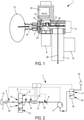
- the device 1 is a compact technical subassembly that can be installed in a portable system or integrated into a fixed installation.
- Device 1 is a device for testing a sample by gas flow.
- the device 1 comprises an orifice 2.
- This orifice 2 is the inlet orifice of the hollow of a hollow needle, arranged in the center of a sealed suction cup 24 arranged to be pressed against a sample 13 (such as a bag of food product or any container having at least one flexible surface of compatible size through which a needle can pass).
- the suction cup avoids the use of sealing septums to carry out a test without polluting the air outside the container.
- the device 1 further comprises means 3 for generating a flow of gas 25 (gas to be analyzed, dilution gas, leak gas, calibration gas) in the device 1 along at least one flow path passing through the orifice 2, by a mass flow meter 4, and by a valve 8 called the selector valve.
- gas 25 gas to be analyzed, dilution gas, leak gas, calibration gas
- Valve 8 is a valve with more than two channels (inlet or outlet), having several possible positions. Each position of the valve 8 corresponds to a specific configuration of opening for the passage of the gas flow 25 or closing to prevent such a passage between some of the inlet and outlet paths of the valve 8.
- Valve 8 is preferably a proportional (preferably slide) valve.
- the valve 8 is for example a valve made from a Mécalectro brand electromagnet, or even a Parker valve.
- Port 2 and valve 8 are common to all flow paths. Along this common part of the flow paths is preferably located a micro-porous filtration element 23.
- the filter 23 is for example a PTFE filter from Millipore or Sartorius.
- the generation means 3 comprise a turbine, or more generally a reversible flow generator with controlled speed in order to be controlled in flow rate or in pressure, for example of the Papst brand.
- the generation means 3 are reversible, that is to say they are arranged to generate both a gaseous flow 25 in aspiration and in expiration (ie in a direction of flow opposite to the aspiration).
- a valve 16 and orifice 2 delimits the two ends of each of the flow paths.
- Valve 16 is a valve with more than two channels (inlet or outlet), having several possible positions. Depending on the position of the valve 16, the valve 16 connects the generation means 3 to the external atmosphere of the device 1 in a first position 17 or to a source 19 of reference gas in a second position 18.
- the valve 16 is by example a Bosch or Univer brand valve.
- the device 1 comprises at least one pressure sensor 5, 6, each pressure sensor 5, 6 being arranged to measure a pressure P r of the gas flow 25 along at least one of the flow paths. More exactly, the pressure Pr measured by each sensor 5 or 6 is a relative pressure (respectively depression or overpressure) generated by the flow 25 (respectively sucked into the device 1 or exhaled from the device 1) with respect to the absolute pressure which would be measured in the absence of this flow 25.
- Each sensor 5, 6 is for example a piezoresistive sensor of the Honeywell, Freescale or Sensortechnics brand.
- the mass flow meter 4 is arranged to measure a parameter representative of the mass flow rate of the gas flow along each flow path.
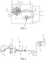
- This parameter is typically an electrical intensity or an electrical voltage, and is preferably proportional to the mass flow rate of the gas flow 25 or linked to the mass flow rate of the gas flow 25 by a calculation programmed and/or stored within calculation means 7 of the device. All the sensory and servo elements 5, 8, 6, 20, 4, 3, 16 are connected to the calculation means 7 by an electrical connection and/or data transfer or command connection (connections shown in dotted lines on the picture 2 ).
- the calculation and control means 7 are represented schematically only on the picture 2 so as not to overload the other figures.
- each is used to refer to any unit (eg sensor or flow path) taken individually in an assembly.
- this set comprises at least one unit (ie for example “at least one sensor” or “at least one flow path”)
- the set comprises a single unit (ie for example a single sensor or a single flow path) and where the word “each” designates this single unit.
- the calculation means 7 only comprise technical electronic and/or software (preferably electronic) means, and comprise a central computer unit, and/or a processor, and/or a dedicated analog or digital circuit, and/or software.
- the mass flowmeter 4 is a mass flowmeter with thermal conductivity.
- the mass flowmeter 4 comprises a heating element (heat source) and two temperature probes.
- the heating element is located between the two temperature sensors so that the heating element and the two temperature sensors are all aligned along the direction of flow of the gas flow at the mass flow meter.
- the mass flowmeter 4 depending on the variation in temperature or quantity of heat between the two temperature probes bordering the heat source, is arranged to determine therefrom the parameter representative of the mass flow rate of the gas flow 25 passing through the flowmeter 4 (i.e. a mass of gas passing through the flow path per unit time).
- the advantage of a mass flow meter, especially with thermal conductivity, is that it has a very fast response time. It will therefore allow access to a leak hole diameter 22 or to a quantification of the presence of a gas of interest with very high measurement speed (typical response time of 3 milliseconds).
- All these flow paths are permitted in the device 1 depending on the position of the valve 8 and the direction of the flow 25 generated by the generating means 3.
- the position of the valve 8 and the direction of the flow 25 generated by the generation means 3 (exhalation or aspiration) at any given time determines the unique (zero or one of the aspiration path, exhalation path, or dilution path) flow path through which the flow 25 of gas at this instant in the device 1.
- valve 8 For a first position 9 of the valve 8, the valve 8 is closed and the gas flow 25 generated by the means 3 cannot flow along any flow path as defined above.
- the means 3 for generating the flow of gas 25 are arranged to draw in a gas to be analyzed coming from a sample 13 so that this gas to be analyzed flows into the device 1 along the suction path.
- the measuring hole 14 is a hole made in a plate 15.
- the plate 15 is typically made of stainless steel.
- the plate 15 is removable so as to be able to replace it typically either in the event of wear of the hole 14 or to change the size of the hole 14 within the device 1.
- the hole 14 is of known size typically from 5 ⁇ m to 150 ⁇ m in diameter. diameter.
- the flow passes through a second hole 21 with a larger diameter (typically around 2 mm) than the measurement hole 14.
- the thickness of this perforated disc 15 is an element for adjusting the desired pressure drop, and is much smaller than the micro-perforated 14 hole size (typically about 10 times smaller)
- This hole 14 is the passage of smallest open area (per unit area perpendicular to the direction of flow 25) for gas flow 25 in device 1 compared to the rest of the entire suction path, and even preferably of the exhalation path and the dilution path.
- Hole 14 is circular in shape.
- the at least one pressure sensor 5, 6 comprises a first pressure (so-called suction) sensor 6 arranged to measure a pressure P r (more exactly a depression, directly linked to the suction force of the turbine 3) of the gas to be analyzed along the suction path, preferably but not limited to between 20 and 500 mbar or wider (between 4 and 500 mbar or between 4 and 1000 mbar or wider depending on the 3) turbine capacities.
- a pressure P r more exactly a depression, directly linked to the suction force of the turbine 3
- the mass flow meter 4 is arranged to measure the parameter representative of the mass flow of the gas to be analyzed along the suction path.
- the calculation means 7 are arranged to quantify the presence of a gas of interest within the gas to be analyzed (this quantified presence being typically a proportion in % of gas of interest in the gas to be analyzed or in mol per liter of gas to be analyzed or in the form of a volume of gas of interest, for example in millilitres), from a measurement of the parameter representative of the mass flow rate of the gas to be analyzed.
- the calculation means 7 are arranged to quantify the presence of the gas of interest in the form of a calculation of a proportion or of a volume of the gas of interest which depends on the diameter of the hole 14 for measurement. In other words, if the diameter or the width of the hole 14 is changed without indicating it (by a program, a command, an adjustment button, etc.) to the device 1, the calculation of the proportion or volume of the gas of interest by device 1 becomes false.
- the first suction pressure sensor 6 is located along the suction path between the orifice 2 and the measurement hole 14, for better measurement accuracy.
- Mass flow meter 4 is located along the suction path so that measurement hole 14 is located along the suction path between port 2 and mass flow meter 4.
- the mass flowmeter 4 is optimized for one or more types of gas having a default value of thermal conductivity (also called thermal conductivity). For gases with a thermal conductivity deviating from this default value, a correction factor must be applied.
- calculation means 7 calculate, by the 1st formula described above, a diameter of the hole 14 ⁇ cal of 100 ⁇ m, the calculation means 7 deduce therefrom either that the proposal of O 2 in the mixture is 100%, or that the proportion of CO 2 in the mixture is 0%, depending on which of these gases is considered to be the gas of interest.
- calculation means 7 calculate, by the formula for ⁇ cal described previously, a diameter of the hole 14 of 135 ⁇ m, the calculation means 7 deduce therefrom either that the proposal of O 2 in the mixture is 0%, ie the proportion of CO 2 in the mixture is 100%, depending on which of these gases is considered to be the gas of interest.
- the calculating means 7 are not obliged to go through two steps of calculating the diameter of the hole 14 ( 1st step, 1st formula) then of deducting the proportion of the gas of interest (2nd step, 2nd formula), but can directly calculate this proportion in a single calculation combining the two steps and therefore the two formulas.
- the calculation means 7 are therefore arranged to quantify the presence of the gas of interest in the form of a calculation of a proportion or of a volume of the gas of interest which preferably depends in an affine manner on the square root of the parameter D m representative of the mass flow.
- the calculation means 7 are arranged to quantify the presence of the gas of interest in the form of a calculation of a proportion or a volume of the gas of interest which depends in an affine manner on the parameter representative of the mass flow.
- the calculation means 7 are arranged to quantify the presence of the gas of interest under the form of a polynomial of degree Z of the parameter representative of the mass flow.
- All the calibration factors A, B, M, N, A ⁇ , M ⁇ , a, b, a ⁇ are stored by the calculating means 7 and are defined in advance, typically by calibrating the device 1 with samples 13 at the known proportions of different gases or with samples 13 each provided with a leak hole 22 of known size.
- each calibration factor depends on the gas considered. For example, one can presuppose a mixture gas of O 2 mixed with a gas of interest of CO 2 , or a mixture gas of He mixed with a gas of interest of CH 4 +NH 3 , etc. .
- the device 1 therefore comprises an interface arranged to define the mixture gas and the gas of interest, and the calculation means 7 are arranged to select the values of the calibration factors as a function of the mixture gases and of interest defined.
- the suction path passes successively through orifice 2, filter 23, pressure sensor 5, valve 8, pressure sensor 6, measuring hole 14, gas sensor 20, passage hole 21 , the flow meter 4, the generating means 3 and the valve 16.
- the device 1 further comprises at least one sensor 20 arranged to quantify the presence of a gas consisting of a given molecule whose thermal conductivity would not be discriminated by another gas or molecule present.
- Calculation means 7 are also arranged to quantify the presence of a first molecule of interest (for example CO 2 in this case) of the gas of interest having a certain thermal conductivity, the device 1 comprising for this along the suction path at least one gas sensor 20 (for example NO sensor 2 in this case, for example of City technology brand) arranged to quantify the presence (proportion in% or in mol.l -1 or volume for example) of at least one other molecule of interest (for example NO 2 in this case) which has a thermal conductivity different at most by 10% compared to the thermal conductivity of the first molecule of interest for identical pressure and temperature conditions, the calculation means 7 being arranged to quantify the presence of the first molecule of interest (CO 2 ) from (simple subtraction) a quanti fication of the presence of the gas of interest (CO 2 +NO 2 ) and a quantification of the presence of the other molecules of interest (NO 2 ).
- a first molecule of interest for example CO 2 in this case
- the device 1 comprising for this along the suction
- Sensor 20 is located along the suction path such that measurement hole 14 is located between port 2 and sensor 20. Sensor 20 is located in a measurement chamber along the suction path between the measurement hole 14 and a passage hole 21 wider than the measurement hole 14.
- the at least one sensor 20 can also be an O 2 sensor, or other (for example an O 2 sensor and NO 2 sensor assembly), for example if the mixing gas comprises a mixture of O 2 and N 2 this in order to discriminate between these two molecules.
- the means 3 for generating the flow of gas 25 are arranged to exhale a dilution gas along the dilution path.
- the dilution path therefore corresponds to the suction path but traversed by the flow of gas 25 in the opposite direction.
- the valve 16 is in its second position 18 connecting the means 3 to the source 19 of gas.
- the solution gas is therefore the reference gas of the source 19 (which is typically a gas cartridge).
- the dilution path is used to increase the volume of sample gas to be analyzed 13.
- sample 13 initially contains as initial gas only a mixture of CO 2 + NO 2 without O 2 , but in too small a quantity to be able to suck this mixture into device 1 by filling the entire suction path: it It is then impossible to determine the proportions of CO 2 and NO 2 in the state.
- sample 13 contains a mixture of CO 2 + NO 2 + O 2 in a quantity sufficient to make measurements.
- the proportion of CO 2 , NO 2 , and O 2 can be determined after dilution as described previously. We can then deduce the proportion of CO 2 and NO 2 before dilution.
- the means 3 for generating the gas flow are arranged to exhale a leak gas along the exhalation path.
- the leak gas (preferably O 2 or air) comes from the outside atmosphere or from the source 19.
- the at least one pressure sensor comprises an exhalation pressure sensor 5 arranged to measure a pressure P r of the leak gas along the exhalation path, preferably but not limited to between 20 and 500 mbar or wider between 4 and 500 mbar or between 4 and 1000 mbar, and in all cases, within the limits of the pressure drop of the pneumatic circuit and the pressure resistance of the members constituting the invention.
- the mass flow meter 4 is arranged to measure a parameter representative of the mass flow of the leak gas along the exhalation path.
- the calculating means 7 are arranged to determine the size of a leak hole 22 of the sample 13 (into which the leak gas exhaled by the device 1 is inserted), from a measurement of the parameter representative of the flow mass.
- Exhalation pressure sensor 5 is located along the exhalation path between flowmeter 4 and port 2.
- the calculating means 7 are arranged to determine the size of the leak hole 22 preferably in the form of a calculation which depends in an affine manner on the square root of the parameter representative of the mass flow rate (cf first formula described above).
- the calculation means 7 are arranged to determine the size of the leak hole 22 in the form of a calculation which depends in an affine manner of the parameter representative of the mass flow.
- the calculation means 7 are arranged to determine the size of the leak hole 22 under the form of a polynomial of degree Z of the parameter representative of the mass flow
- the calculation means 7 are arranged to determine the size of the hole 22 also from a pressure measurement by the sensor 5 of exhalation pressure, for example in the form of a calculation which depends preferably in an affine way of the inverse of the fourth root of the pressure measurement.
- the calculation means 7 are arranged to determine the size of the hole 22 according to the formula: at D m 2 P r 4 + b with D m the parameter representative of the mass flow rate measured by the flow meter 4, P r the pressure measured by the exhalation pressure sensor 5, and a and b digital calibration coefficients.
- the calculation means 7 are arranged to trigger a determination of the size of the hole 22 for a value of the pressure measured by the exhalation pressure sensor 5 corresponding to an exhalation pressure reference value, the calculation means 7 being arranged to determine the size of the hole 22 from a value of the parameter representative of the mass flow D m measured simultaneously with the pressure measurement measuring the pressure value corresponding to the exhalation pressure reference value.
- the calculation means 7 are for example arranged to determine the size of the hole 22 according to the formula: at ⁇ D m 2 + b with D m the representative parameter of the mass flow measured by the flow meter 4, and a ⁇ and b digital calibration coefficients.
- the exhalation path therefore passes successively through the valve 16, the generation means 3, the flowmeter 4, the two parts which separate before the measurement hole 14 and which meet after the measurement hole 14, the valve 8, the pressure sensor 5, the filter 23, and the orifice 2.
- valve 8 in its fourth position 12 is arranged to complete the exhalation path with a short-circuit path passing through the pantry 2 and the flow generation means 3 but not passing through the flowmeter 4 (this path short circuit therefore not forming part of the flow paths as defined above).
- Valve 8 is arranged to adjust the total flow passing through the exhalation path and the short-circuit path. This allows greater flow rates D m , and therefore to measure other scales of diameter of leak hole 22 or to quickly inflate sample 13 to test its solidity until it bursts due to successive fatigue or stress phenomena.
- the calculation means 7 are arranged to deduce, from a flow measurement D m along the exhalation path by the mass flow meter 4, the flow passing in total through the exhalation path and the short-term path. circuit when valve 8 opens this short-circuit path.
- the calculation means 7 apply a simple multiplication, by a calibration coefficient, of the flow rate D m measured by the mass flow meter 4 to obtain the flow rate passing in total through the expiration path and the short-circuit path when the valve 8 opens this short circuit path.
- the calculation means 7 modify the value of the calibration coefficients a and a ⁇ when determining the size of the leak hole 22, to take into account that the flow passing in total through the path of exhalation and the short-circuit path is greater than the measurement, by the flowmeter 4, of the parameter D m representative of the mass flow rate of the gas leak gas along the exhalation path.
- the method comprises an expiration (by the means 3) of the dilution gas (CO 2 coming from the source 19) flowing along the dilution path into the sample 13 comprising an initial gas (mixture of CO 2 and NO 2 ) which preferably but not necessarily comprises the gas of interest.
- the method according to the invention comprises an aspiration (by the means 3) of the gas to be analyzed (O 2 + CO 2 + NO 2 ) coming from the sample 13, the said gas to be aspirated to be analyzed flowing along the suction path beginning with orifice 2 and narrowing locally at the level of measurement hole 14.
- the quantification of the presence of the gas of interest includes a calculation as described for the description of device 1.
- the gas of interest comprises from 0 to 100% of a first molecule of interest (CO 2 ) having a certain thermal conductivity, and from 0 to 100% of other molecules of interest ( NO 2 ) which have a thermal conductivity different at most by 10% relative to the thermal conductivity of the first molecule of interest for identical temperature and pressure conditions.
- the method according to the invention then comprises an expiration of the leak gas (preferably outside air or the gas from the source 19 or a tracer gas making it possible to locate the leak, coloring or measurable by other external means) s flowing along the exhalation path ending in port 2.
- the leak gas preferably outside air or the gas from the source 19 or a tracer gas making it possible to locate the leak, coloring or measurable by other external means
- the method according to the invention then comprises a determination, by the calculation means 7, of the size of the leak hole 22 in the sample 13, from this last measurement of the parameter representative of the mass flow rate.
- the determination of the size of the leak hole 22 includes a calculation as described for the description of device 1.
- the method according to the invention then comprises an adjustment, by the valve 8 arranged to complete the exhalation path with a short-circuit path passing through the pantry and the flow generation means but not passing through the flowmeter, of the flow passing in total through the exhalation path and the short-circuit path, said valve opening the short-circuit path according to an opening of adjustable size.
- the method according to the invention then comprises a determination, by the means 7, and from the flow measurement along the exhalation path, of the flow passing in total through the exhalation path and the short-circuit path when the valve opens the short circuit path.
- the calculation means 7 modify the value of the calibration coefficients a and a ⁇ when determining the size of the leak hole 22, to take into account that the flow passing in total through the exhalation path and the short-circuit path is greater than the measurement, by the flow meter 4, of the parameter D m representative of the mass flow rate of the gas leak gas along the exhalation path.
- the gas flow is pushed to a high value, possibly at a controlled flow to test the bursting of the sample 13 in a desired dynamic.
- Sample 13 may be subjected to external mechanical stresses such as an overwrap clamping, atmospheric pressure, immersion in a fluid, etc...
- the different steps of this process can be reversed, or done simultaneously or be optional.
- the calibration step is not necessary before the leak measurement.
- the leak measurement is completely independent of the gas analysis, and the leak measurement can be performed before the gas analysis or without the gas analysis.
- the leak measurement can be carried out simultaneously with the dilution, preferably once an equilibrium pressure has been reached, the expired dilution gas also playing the role of expired leak gas.
Landscapes
- Physics & Mathematics (AREA)
- General Physics & Mathematics (AREA)
- Chemical & Material Sciences (AREA)
- Health & Medical Sciences (AREA)
- Life Sciences & Earth Sciences (AREA)
- Analytical Chemistry (AREA)
- Biochemistry (AREA)
- General Health & Medical Sciences (AREA)
- Immunology (AREA)
- Pathology (AREA)
- Engineering & Computer Science (AREA)
- Medicinal Chemistry (AREA)
- Food Science & Technology (AREA)
- Combustion & Propulsion (AREA)
- Fluid Mechanics (AREA)
- Measuring Volume Flow (AREA)
- Sampling And Sample Adjustment (AREA)
Claims (20)
- Vorrichtung zum Prüfen eines Probekörpers (13) mittels Gasströmung, die das Folgende aufweist:- eine Öffnung (2),- Mittel (3) zur Erzeugung eines Gasflusses (25) in der Vorrichtung entlang mindestens eines Strömungswegs durch die Öffnung,- mindestens einen Drucksensor (5, 6), wobei jeder Drucksensor so angeordnet ist, dass er den Druck des Gasstroms entlang mindestens eines Strömungswegs misst, und- einen Massendurchflussmesser (4), der so angeordnet ist, dass er einen Parameter misst, der für den Massendurchfluss des Gasstroms entlang jedes Durchflusswegs repräsentativ ist, und wobei- der mindestens eine Strömungsweg einen Ausströmungsweg umfasst, der in der Öffnung endet,- das Mittel zur Erzeugung des Gasflusses so angeordnet ist, dass es ein Leckgas entlang des Ausströmungsweges in den Probekörper abgibt,- der mindestens eine Drucksensor einen Ausströmungsdrucksensor (5) umfasst, der so angeordnet ist, dass er einen Druck des Leckgases entlang des Ausströmungswegs misst,- der Massendurchflussmesser so angeordnet ist, dass er einen Parameter misst, der für die Massendurchflussrate des Leckgases entlang des Ausströmungswegs repräsentativ ist, und wobei die Vorrichtung dadurch gekennzeichnet ist, dass sieferner eine Berechnungseinrichtung (7) umfasst, die so eingerichtet ist, dass sie die Größe einer Leckage-Öffnung (22) aus einer Messung des Parameters bestimmt, der für die Massenstromrate entlang des Ausströmungswegs repräsentativ ist, wobei der Massendurchflussmesser ein Wärmeleitfähigkeits-Massendurchflussmesser ist.
- Vorrichtung nach Anspruch 1, dadurch gekennzeichnet, dass der Ausströmungsdrucksensor entlang des Ausströmungsweges zwischen dem Durchflussmesser und der Öffnung angeordnet ist.
- Vorrichtung nach einem der vorhergehenden Ansprüche, dadurch gekennzeichnet, dass die Berechnungseinrichtung so eingerichtet ist, dass sie die Größe der Leckage-Öffnung mittels einer Berechnung bestimmt, die affin von der Quadratwurzel des Parameters abhängt, der für den Massenstrom entlang des Ausströmungswegs repräsentativ ist.
- Vorrichtung nach einem der vorhergehenden Ansprüche, dadurch gekennzeichnet, dass die Recheneinrichtung so eingerichtet ist, dass sie die Größe der Leckage-Öffnung anhand einer Druckmessung entlang des Ausströmungswegs durch den Ausströmungsdrucksensor bestimmt.
- Vorrichtung nach Anspruch 4, dadurch gekennzeichnet, dass die Berechnungseinrichtung so eingerichtet ist, dass sie die Größe der Leckage-Öffnung in Form einer Berechnung bestimmt, die affin von der Umkehrung der vierten Wurzel der Druckmessung entlang des Ausströmungswegs abhängt.
- Vorrichtung nach Anspruch 5, dadurch gekennzeichnet, dass die Berechnungseinrichtung so beschaffen ist, dass sie die Größe des Leckage-Öffnung nach der folgenden Formel bestimmt:

- Vorrichtung nach einem der Ansprüche 1 bis 3, dadurch gekennzeichnet, dass die Recheneinrichtung ausgebildet ist zum Initiieren einer Bestimmung der Größe der Leckage-Öffnung für einen Wert des Drucks entlang des Ausströmungswegs, der von dem Ausströmungsdrucksensor gemessen wird und einem Ausströmungsdruck-Referenzwert entspricht, wobei die Recheneinrichtung so ausgebildet ist, dass sie die Größe der Leckage-Öffnung aus einem Wert des Parameters bestimmt, der für den Massenstrom entlang des Ausströmungswegs repräsentativ ist und gleichzeitig mit der Druckmessung gemessen wird, die den Druckwert misst, der dem Ausströmungsdruck-Referenzwert entspricht.
- Vorrichtung nach Anspruch 7, dadurch gekennzeichnet, dass die Berechnungsmittel so beschaffen sind, dass sie die Größe der Leckage-Öffnung nach der folgenden Formel bestimmen :

- Vorrichtung nach einem der vorhergehenden Ansprüche, dadurch gekennzeichnet, dass der mindestens eine Strömungsweg einen Kalibrierungsweg durch die Öffnung umfasst, und dass sich der Kalibrierungsweg innerhalb der Vorrichtung lokal an einer Messöffnung (14) verengt, wobei die Recheneinrichtung so angeordnet ist, dass sie das Folgende durchführt:- Bestimmen der Größe der Messöffnung anhand einer Messung des für den Massendurchsatz repräsentativen Parameters entlang des Kalibrierungspfads, und- Anpassung der Kalibrierkoeffizienten zur Berechnung der Größe einer Leckage-Öffnung, wenn die Bestimmung der Größe der Messbohrung nicht mit der tatsächlichen Größe der von den Berechnungsmitteln gespeicherten Messbohrung übereinstimmt.
- Vorrichtung nach einem der vorhergehenden Ansprüche, dadurch gekennzeichnet, dass sie ein Ventil (8) umfasst, das so beschaffen ist, dass es den Ausströmungsweg um einen Kurzschlussweg ergänzt, der durch den Massendurchflussmesser und die Strömungserzeugungseinrichtung, aber nicht durch die Leitung verläuft, wobei das Ventil so beschaffen ist, dass es die insgesamt durch den Ausströmungsweg und den Kurzschlussweg verlaufende Strömungsrate einstellt.
- Verfahren zum Testen eines Probekörpers mittels eines Gasflusses, umfassend:- eine Abgabe eines Leckgases in den Probekörper, das entlang eines Ausströmungsweges strömt, der in einer mit dem Probekörper (13) verbundenen Öffnung (2) endet,- eine Druckmessung des Leckgases entlang des Ausströmungsweges,- eine Messung eines Parameters, der für den Massendurchsatz des Leckgases entlang des Ausströmungsweges repräsentativ ist, wobei das Verfahren gekennzeichnet ist durch ein- Bestimmen der Größe einer Leckage-Öffnung (22) in dem Probekörper aus der Messung des Parameters, der für die Massenflussrate entlang des Ausströmungswegs repräsentativ ist,- wobei die Messung eines für den Massendurchsatz repräsentativen Parameters durch einen Wärmeleitfähigkeits-Massendurchflussmesser (4) erfolgt.
- Verfahren nach Anspruch 11, dadurch gekennzeichnet, dass die Druckmessung mittels eines Ausströmungsdrucksensors (5) durchgeführt wird, der entlang des Ausströmungsweges zwischen dem Durchflussmesser und dem Probekörper angeordnet ist.
- Verfahren nach einem der Ansprüche 11 bis 12, dadurch gekennzeichnet, dass die Bestimmung der Größe der Leckage-Öffnung die Berechnung der Größe der Leckage-Öffnung umfasst, die affin von der Quadratwurzel des Parameters abhängt, der für den Massenfluss entlang des Ausströmungswegs repräsentativ ist.
- Verfahren nach einem der Ansprüche 11 bis 13, dadurch gekennzeichnet, dass die Bestimmung der Größe der Leckage-Öffnung ferner anhand des entlang des Ausströmungswegs gemessenen Drucks erfolgt.
- Verfahren nach Anspruch 1, dadurch gekennzeichnet, dass die Bestimmung der Größe der Leckage-Öffnung die Berechnung der Größe der Leckage-Öffnung umfasst, die affin von der Umkehrung der vierten Wurzel der Druckmessung entlang des Ausströmungswegs abhängig ist.
- Verfahren nach Anspruch 15, dadurch gekennzeichnet, dass die Bestimmung der Leckageöffnungs-Größe eine Berechnung der Leckageöffnungs-Größe nach der folgenden Formel umfasst:

- Verfahren nach einem der Ansprüche 11 bis 13, dadurch gekennzeichnet, dass die Bestimmung der Größe der Leckage-Öffnung für einen Wert des gemessenen Drucks entlang des Ausströmungspfads ausgelöst wird, der einem Druckreferenzwert entspricht, wobei die Bestimmung der Größe der Leckage-Öffnung aus einem Wert des Parameters erfolgt, der für den Massenstrom entlang des Ausströmungspfads repräsentativ ist und gleichzeitig mit der Druckmessung gemessen wird, die den Druckwert misst, der dem Druckreferenzwert entspricht.
- Verfahren nach Anspruch 19, dadurch gekennzeichnet, dass die Bestimmung der Leckageöffnungs-Größe eine Berechnung der Leckageöffnungs-Größe nach der folgenden Formel umfasst:

- Verfahren nach einem der Ansprüche 11 bis 18, dadurch gekennzeichnet, dass der mindestens eine Strömungsweg einen Kalibrierungsweg umfasst, der durch die Öffnung verläuft und sich an einer Messöffnung (14) lokal verengt, wobei das erfindungsgemäße Verfahren das Folgende umfasst:- ein Abgeben eines Kalibriergases entlang des Kalibrierpfades,- eine Druckmessung des Kalibriergases entlang des Kalibrierpfades,- eine Messung eines Parameters, der für den Massendurchsatz des Kalibriergases entlang des Kalibrierpfads repräsentativ ist,- eine Bestimmung der Größe der Messöffnung anhand einer Messung des für den Massendurchfluss repräsentativen Parameters, und- eine Anpassung der numerischen Koeffizienten für die Berechnung der Größe einer Leckage-Öffnung, wenn die Bestimmung der Größe der Messbohrung nicht mit einer tatsächlichen Größe der Messbohrung übereinstimmt, die von Berechnungsmitteln gespeichert wird.
- Verfahren nach einem der Ansprüche 11 bis 19, dadurch gekennzeichnet, dass es die Einstellung der Durchflussmenge, die insgesamt durch den Ausströmungsweg und den Kurzschlussweg fließt, durch ein Ventil (8) umfasst, das so angeordnet ist, dass es den Ausströmungsweg mit einem Kurzschlussweg ergänzt, der durch die Leitung und die Durchflusserzeugungseinrichtung, aber nicht durch den Durchflussmesser verläuft.
Priority Applications (1)
| Application Number | Priority Date | Filing Date | Title |
|---|---|---|---|
| PL18170505T PL3385696T3 (pl) | 2012-12-21 | 2013-12-19 | Urządzenie oraz sposób określania rozmiaru otworu wyciekowego |
Applications Claiming Priority (3)
| Application Number | Priority Date | Filing Date | Title |
|---|---|---|---|
| FR1262680A FR3000215B1 (fr) | 2012-12-21 | 2012-12-21 | Dispositif et procede de test d'un echantillon, en particulier de discrimination d'un gaz d'un echantillon |
| EP13818740.6A EP2936145B1 (de) | 2012-12-21 | 2013-12-19 | Vorrichtung und verfahren zur unterscheidung von gasen in einer probe |
| PCT/EP2013/077538 WO2014096287A1 (fr) | 2012-12-21 | 2013-12-19 | Dispositif et procede de discrimination d'un gaz dans un echantillon |
Related Parent Applications (2)
| Application Number | Title | Priority Date | Filing Date |
|---|---|---|---|
| EP13818740.6A Division EP2936145B1 (de) | 2012-12-21 | 2013-12-19 | Vorrichtung und verfahren zur unterscheidung von gasen in einer probe |
| EP13818740.6A Division-Into EP2936145B1 (de) | 2012-12-21 | 2013-12-19 | Vorrichtung und verfahren zur unterscheidung von gasen in einer probe |
Publications (2)
| Publication Number | Publication Date |
|---|---|
| EP3385696A1 EP3385696A1 (de) | 2018-10-10 |
| EP3385696B1 true EP3385696B1 (de) | 2022-02-23 |
Family
ID=47902232
Family Applications (2)
| Application Number | Title | Priority Date | Filing Date |
|---|---|---|---|
| EP18170505.4A Active EP3385696B1 (de) | 2012-12-21 | 2013-12-19 | Vorrichtung und verfahren zur bestimmung der grösse einer leckage |
| EP13818740.6A Active EP2936145B1 (de) | 2012-12-21 | 2013-12-19 | Vorrichtung und verfahren zur unterscheidung von gasen in einer probe |
Family Applications After (1)
| Application Number | Title | Priority Date | Filing Date |
|---|---|---|---|
| EP13818740.6A Active EP2936145B1 (de) | 2012-12-21 | 2013-12-19 | Vorrichtung und verfahren zur unterscheidung von gasen in einer probe |
Country Status (10)
| Country | Link |
|---|---|
| US (2) | US10197469B2 (de) |
| EP (2) | EP3385696B1 (de) |
| CN (2) | CN108225972B (de) |
| CA (1) | CA2838187C (de) |
| DK (2) | DK3385696T3 (de) |
| ES (2) | ES2686623T3 (de) |
| FR (1) | FR3000215B1 (de) |
| HK (1) | HK1215303A1 (de) |
| PL (2) | PL3385696T3 (de) |
| WO (1) | WO2014096287A1 (de) |
Families Citing this family (9)
| Publication number | Priority date | Publication date | Assignee | Title |
|---|---|---|---|---|
| US20160160635A1 (en) * | 2013-07-24 | 2016-06-09 | Ikm Production Technology As | Measurement device |
| DE102016100817A1 (de) * | 2016-01-19 | 2017-07-20 | Phoenix Contact E-Mobility Gmbh | Gehäuseteil mit einer Prüfstelle zur Dichtigkeitsprüfung |
| JP6839440B2 (ja) * | 2017-01-19 | 2021-03-10 | ヤマハファインテック株式会社 | ガスセンサアレイ及びガス漏れ検知装置 |
| JP2018159563A (ja) * | 2017-03-22 | 2018-10-11 | ヤマハファインテック株式会社 | ガスセンサ装置及びガス漏れ検知装置 |
| TWI654415B (zh) * | 2017-08-25 | 2019-03-21 | 大陸商賽默飛世爾(上海)儀器有限公司 | 流體取樣裝置 |
| CN109342347A (zh) * | 2018-11-05 | 2019-02-15 | 安徽建筑大学 | 一种多模式气体分析装置以及分析方法 |
| CN114636516A (zh) * | 2021-04-06 | 2022-06-17 | 上海东贝真空设备有限公司 | 药品包装容器密封完整性检查用阳性样品校准装置及方法 |
| CN113447618B (zh) * | 2021-06-29 | 2023-11-03 | 重庆大学 | 多传感器电子鼻的阶梯形气室、双进样检测系统及方法 |
| CN116387236B (zh) * | 2023-06-01 | 2023-08-18 | 深圳市晶利德实业有限公司 | 一种集成电路加工机械手 |
Family Cites Families (68)
| Publication number | Priority date | Publication date | Assignee | Title |
|---|---|---|---|---|
| US3818752A (en) * | 1971-04-28 | 1974-06-25 | N Lindeberg | Method and apparatus for testing tightness |
| US3852996A (en) * | 1973-06-22 | 1974-12-10 | Us Health | Automotive exhaust system leak test |
| US4223293A (en) * | 1979-01-22 | 1980-09-16 | Ford Motor Company | Terminal pin arrangement for an exhaust gas sensor |
| US4685331A (en) * | 1985-04-10 | 1987-08-11 | Innovus | Thermal mass flowmeter and controller |
| US4787254A (en) * | 1987-02-20 | 1988-11-29 | Briggs Technology, Inc. | Mass flow meter |
| US4776206A (en) * | 1987-08-11 | 1988-10-11 | Xetron Corporation | Leak testing by gas flow signature analysis |
| US4896528A (en) * | 1987-11-16 | 1990-01-30 | Lewis Donald E | Tank bottom leak testing and apparatus |
| US4898021A (en) * | 1988-11-30 | 1990-02-06 | Westinghouse Electric Corp. | Quantitative air inleakage detection system and method for turbine-condenser systems |
| JP2820508B2 (ja) * | 1990-07-06 | 1998-11-05 | 保安工業株式会社 | ガス漏れ検知装置 |
| US5513516A (en) * | 1992-05-01 | 1996-05-07 | Visi-Pack, Inc. | Method and apparatus for leak testing a container |
| US5546435A (en) * | 1992-11-16 | 1996-08-13 | Abb Atom Ab | Fission product leak detection in a pressurized-water reactor |
| US5369984A (en) * | 1993-08-31 | 1994-12-06 | Environmental Systems Products, Inc. | Method and apparatus for testing of tank integrity of vehicle fuel systems |
| JP3376250B2 (ja) * | 1996-08-13 | 2003-02-10 | 大和製罐株式会社 | 中空部材の漏洩検査装置および方法 |
| US6327915B1 (en) * | 1999-06-30 | 2001-12-11 | Micro Motion, Inc. | Straight tube Coriolis flowmeter |
| CN2397491Y (zh) * | 1999-11-05 | 2000-09-20 | 蔡凤英 | 带有标准气孔防漏气装置的氧量检测器 |
| US6308556B1 (en) * | 1999-12-17 | 2001-10-30 | Atc, Inc. | Method and apparatus of nondestructive testing a sealed product for leaks |
| US6584828B2 (en) * | 1999-12-17 | 2003-07-01 | Atc, Inc. | Method and apparatus of nondestructive testing a sealed product for leaks |
| JP4671462B2 (ja) * | 2000-02-22 | 2011-04-20 | パナソニック株式会社 | ニッケル水素二次電池の気密検査方法 |
| DE10133232A1 (de) * | 2000-07-10 | 2002-06-13 | Denso Corp | Verfahren zur Herstellung eines verbesserten Gasfühlerdichtungsaufbaus |
| CN1374516A (zh) * | 2001-03-13 | 2002-10-16 | 上海南汇新海印染机械配件厂 | 管道气体泄露的探测方法 |
| US6382011B1 (en) * | 2001-05-09 | 2002-05-07 | Mocon, Inc. | Apparatus for providing leakage calibration in packages |
| US6609414B2 (en) * | 2001-07-19 | 2003-08-26 | Mocon, Inc. | Apparatus for conducting leakage tests on sealed packages |
| US6807851B2 (en) * | 2001-07-25 | 2004-10-26 | Denso Corporation | Leak-check apparatus of fuel-vapor-processing system, fuel-temperature estimation apparatus and fuel-temperature-sensor diagnosis apparatus |
| JP3655569B2 (ja) * | 2001-09-06 | 2005-06-02 | 大陽日酸株式会社 | ガス成分濃度測定方法及び装置 |
| JP3930437B2 (ja) * | 2002-04-11 | 2007-06-13 | 株式会社日本自動車部品総合研究所 | 蒸発燃料処理装置の故障診断方法および故障診断装置 |
| JP4567454B2 (ja) * | 2002-09-26 | 2010-10-20 | インフィコン ゲゼルシャフト ミット ベシュレンクテル ハフツング | スニフティング漏れ探査器のための試験漏れ装置 |
| US6840086B2 (en) * | 2003-03-06 | 2005-01-11 | Cincinnati Test Systems, Inc. | Method and apparatus for detecting leaks |
| US6834529B2 (en) * | 2003-03-20 | 2004-12-28 | Siemens Building Technologies, Inc. | Method for measuring the atmosphere within an enclosure using a self-drilling sensor well |
| US7435381B2 (en) * | 2003-05-29 | 2008-10-14 | Siemens Healthcare Diagnostics Inc. | Packaging of microfluidic devices |
| US7682428B2 (en) * | 2003-08-26 | 2010-03-23 | Teijin Pharma Limited | Oxygen concentration apparatus |
| JP4007299B2 (ja) * | 2003-10-07 | 2007-11-14 | トヨタ自動車株式会社 | 燃料処理システムの故障診断装置 |
| CN1227519C (zh) * | 2003-11-12 | 2005-11-16 | 安徽中科智能高技术有限责任公司 | 一种气体泄漏量可调样件和检测方法 |
| JP2005299394A (ja) * | 2004-04-06 | 2005-10-27 | Mitsubishi Electric Corp | 蒸散燃料ガスリーク検出装置 |
| JP4407373B2 (ja) * | 2004-05-13 | 2010-02-03 | 株式会社デンソー | ガスセンサ素子 |
| CN1997881B (zh) * | 2005-01-10 | 2010-09-22 | 膜康公司 | 探测气密封包装中泄漏的仪器和方法 |
| JP4684300B2 (ja) * | 2005-02-02 | 2011-05-18 | モコン・インコーポレーテッド | 密封シールされた包装における漏洩の大きさの検出及び報告用装置及び方法 |
| US7571636B2 (en) * | 2005-02-14 | 2009-08-11 | Mocon, Inc. | Detecting and reporting the location of a leak in hermetically sealed packaging |
| JP2007231814A (ja) * | 2006-02-28 | 2007-09-13 | Denso Corp | 漏れ診断装置 |
| JP2007231813A (ja) * | 2006-02-28 | 2007-09-13 | Denso Corp | 燃料性状判定装置、漏れ検査装置、および燃料噴射量制御装置 |
| JP4684135B2 (ja) * | 2006-03-03 | 2011-05-18 | 株式会社フジキン | 配管路の漏洩検査方法及び漏洩検査装置 |
| WO2008046420A1 (en) * | 2006-10-18 | 2008-04-24 | Pbi-Dansensor A/S | A method for determining a volume |
| US7581427B2 (en) * | 2006-11-14 | 2009-09-01 | Mocon, Inc. | Workspace analyte sensing system and method using a fan to move samples from the workspace to the sensor |
| JPWO2008105197A1 (ja) * | 2007-02-28 | 2010-06-03 | 株式会社山武 | フローセンサ |
| GB2451284B (en) * | 2007-07-26 | 2012-10-17 | Abb Ltd | Flowmeter |
| DE102007037166A1 (de) * | 2007-08-07 | 2009-02-19 | Endress + Hauser Flowtec Ag | Meßgerät |
| JP5088779B2 (ja) * | 2007-08-07 | 2012-12-05 | 日本ゴア株式会社 | 電気音響変換装置、電子機器、及び防水カバー、並びに、電気音響変換装置の通気試験方法 |
| DE102007057944A1 (de) * | 2007-12-01 | 2009-06-04 | Inficon Gmbh | Verfahren und Vorrichtung zur Dichtheitsprüfung |
| CN101470065A (zh) * | 2007-12-28 | 2009-07-01 | 中国航天科技集团公司第五研究院第五一〇研究所 | 用定量气体法测量正压漏孔全漏率的方法 |
| US8143603B2 (en) * | 2008-02-28 | 2012-03-27 | Ricoh Company, Ltd. | Electrostatic latent image measuring device |
| DE102008002224A1 (de) * | 2008-06-05 | 2009-12-10 | Robert Bosch Gmbh | Verfahren zur Erkennung von Leckagen in einem Tanksystem |
| CN101358948A (zh) * | 2008-08-21 | 2009-02-04 | 华中科技大学 | 一种地下储气井金属井筒检测装置 |
| IL205614A0 (en) * | 2009-05-08 | 2010-11-30 | Renalsense Ltd | Device and method for monitoring renal function |
| CN102460028B (zh) * | 2009-06-05 | 2015-06-17 | 爱克斯崔里斯科技有限公司 | 气体探测器装置 |
| CN101598626A (zh) * | 2009-07-14 | 2009-12-09 | 首钢总公司 | 一种用于rh真空泄漏部位确定方法 |
| CN201464449U (zh) * | 2009-07-27 | 2010-05-12 | 上海莫克电子技术有限公司 | 密封容器上的气体检测装置 |
| CN101713698A (zh) * | 2009-07-27 | 2010-05-26 | 山东大学 | 一种真空检漏系统 |
| GB0916908D0 (en) * | 2009-09-25 | 2009-11-11 | Molins Plc | Measurement apparatus |
| WO2011108981A1 (en) * | 2010-03-01 | 2011-09-09 | Provtagaren Ab | Flow regulating system and monitoring device comprising said flow regulating system for the detection of air borne analytes |
| WO2011159816A1 (en) * | 2010-06-15 | 2011-12-22 | Expro Meters, Inc. | Minimally intrusive monitoring of a multiphase process flow using a tracer |
| US8453493B2 (en) * | 2010-11-02 | 2013-06-04 | Agilent Technologies, Inc. | Trace gas sensing apparatus and methods for leak detection |
| CN102269666B (zh) * | 2011-03-31 | 2012-09-12 | 哈尔滨工业大学(威海) | 一种用于超低泄露率检测的气体样品富集装置及方法 |
| DE102011086486B4 (de) * | 2011-11-16 | 2023-01-19 | Inficon Gmbh | Vorrichtung und Verfahren zur schnellen Lecksuche an formsteifen/schlaffen Verpackungen ohne Zusatz von Prüfgas |
| EP2672246B1 (de) * | 2012-06-05 | 2017-07-19 | Sciemetric Instruments Inc. | Verfahren und Systeme zur Leckprüfung |
| US20150226629A1 (en) * | 2012-09-04 | 2015-08-13 | Atonarp Inc. | System and method for leak inspection |
| US20140356523A1 (en) * | 2013-05-29 | 2014-12-04 | GM Global Technology Operations LLC | Materials, methods, and apparatus for improving leak robustness |
| DE102013217288A1 (de) * | 2013-08-29 | 2015-03-05 | Inficon Gmbh | Dichtheitsprüfung während der Evakuierung einer Folienkammer |
| JP6636044B2 (ja) * | 2015-12-14 | 2020-01-29 | 株式会社フクダ | 漏れ検査装置及び方法 |
| DE102015226360A1 (de) * | 2015-12-21 | 2017-06-22 | Inficon Gmbh | Grobleckmessung eines inkompressiblen Prüflings in einer Folienkammer |
-
2012
- 2012-12-21 FR FR1262680A patent/FR3000215B1/fr active Active
-
2013
- 2013-12-19 EP EP18170505.4A patent/EP3385696B1/de active Active
- 2013-12-19 ES ES13818740.6T patent/ES2686623T3/es active Active
- 2013-12-19 PL PL18170505T patent/PL3385696T3/pl unknown
- 2013-12-19 DK DK18170505.4T patent/DK3385696T3/da active
- 2013-12-19 CN CN201810053504.8A patent/CN108225972B/zh active Active
- 2013-12-19 EP EP13818740.6A patent/EP2936145B1/de active Active
- 2013-12-19 DK DK13818740.6T patent/DK2936145T3/en active
- 2013-12-19 WO PCT/EP2013/077538 patent/WO2014096287A1/fr active Application Filing
- 2013-12-19 US US14/653,613 patent/US10197469B2/en active Active
- 2013-12-19 CN CN201380073513.9A patent/CN105026927B/zh active Active
- 2013-12-19 PL PL13818740T patent/PL2936145T3/pl unknown
- 2013-12-19 ES ES18170505T patent/ES2913770T3/es active Active
- 2013-12-20 CA CA2838187A patent/CA2838187C/fr active Active
-
2016
- 2016-03-21 HK HK16103240.4A patent/HK1215303A1/zh unknown
-
2018
- 2018-11-08 US US16/184,037 patent/US11874199B2/en active Active
Also Published As
| Publication number | Publication date |
|---|---|
| ES2913770T3 (es) | 2022-06-06 |
| FR3000215B1 (fr) | 2016-02-05 |
| PL2936145T3 (pl) | 2018-11-30 |
| EP2936145A1 (de) | 2015-10-28 |
| US10197469B2 (en) | 2019-02-05 |
| ES2686623T3 (es) | 2018-10-18 |
| EP3385696A1 (de) | 2018-10-10 |
| CA2838187C (fr) | 2015-01-27 |
| CA2838187A1 (fr) | 2014-03-13 |
| EP2936145B1 (de) | 2018-06-13 |
| DK2936145T3 (en) | 2018-09-24 |
| CN108225972B (zh) | 2021-04-09 |
| CN105026927B (zh) | 2018-02-16 |
| FR3000215A1 (fr) | 2014-06-27 |
| CN108225972A (zh) | 2018-06-29 |
| PL3385696T3 (pl) | 2022-06-13 |
| CN105026927A (zh) | 2015-11-04 |
| US20150362400A1 (en) | 2015-12-17 |
| WO2014096287A1 (fr) | 2014-06-26 |
| DK3385696T3 (da) | 2022-05-23 |
| US11874199B2 (en) | 2024-01-16 |
| US20190072453A1 (en) | 2019-03-07 |
| HK1215303A1 (zh) | 2016-08-19 |
Similar Documents
| Publication | Publication Date | Title |
|---|---|---|
| EP3385696B1 (de) | Vorrichtung und verfahren zur bestimmung der grösse einer leckage | |
| CN101622530B (zh) | 用于测试气体泄漏检测的方法和装置 | |
| WO2011089367A1 (fr) | Mesure de parametres lies a l'ecoulement de fluides dans un materiau poreux | |
| EP3023766B1 (de) | Verfahren und vorrichtung zur durchlässigkeitsmessung mit massenspektrometrie | |
| WO2006114509A1 (fr) | Methode et dispositif pour evaluer des parametres d'ecoulement et des parametres electriques d'un milieu poreux | |
| JP2008309785A (ja) | 減衰全反射センサー | |
| JP2022009730A (ja) | 光学的測定による容器の完全性を判定するためのシステムおよび方法 | |
| US20140013824A1 (en) | Method and apparatus for increasing the speed and/or resolution of gas permeation measurements | |
| FR2640752A1 (fr) | Procede et appareil pour determiner la densite d'un gaz | |
| US20070089488A1 (en) | Lighter device with flow restrictor and methods of manufacturing and testing same | |
| EP4065959B1 (de) | Verfahren zum charakterisieren verbindungen in einer messkammer, die eine schwankung der relativen feuchtigkeit aufweist | |
| FR3000208A1 (fr) | Dispositif et procede de test d'un echantillon, en particulier de mise sous contrainte d'un echantillon | |
| EP0588892A1 (de) | Vorrichtung zum spektralphotometrischen dosieren vonwaessrigen fluessigkeiten. | |
| JPH0510845A (ja) | 移動貯蔵タンクの漏洩検査装置 | |
| EP0316375B1 (de) | Automatisches verfahren zur messwertberichtigung eines chromatographen und system zu seiner durchführung | |
| EP2277016A2 (de) | Verfahren und einrichtung zur bestimmung einer durchflussmessgrösse eines fluides | |
| Jannot et al. | A simultaneous determination of permeability and Klinkenberg coefficient from an unsteady-state pulse-decay experiment | |
| Johansson | Gas transport in porous media: an investigation of the hydrodynamic to free molecular flow regime | |
| FR2522147A1 (fr) | Procede et dispositif pour detecter des fuites d'un melange gaz-air hors de circuits de fluide fermes | |
| FR2914749A1 (fr) | Dispositif de prelevement automatique successif en ligne d'une serie d'echantillons d'un liquide a analyser ainsi que procede mis en oeuvre suite a l'utilisation de ce dispositif | |
| WO2012020178A1 (fr) | Procédé et dispositif de mesure d'absorption d'infrarouges et éthylomètre comportant un tel dispositif | |
| WO2018127667A2 (fr) | Dispositif de mesure de la quantité d'oxygène présente dans un gaz, et module de séparation d'air comprenant un tel dispositif de mesure | |
| FR2873812A1 (fr) | Dispositif de prelevement de composes volatils |
Legal Events
| Date | Code | Title | Description |
|---|---|---|---|
| PUAI | Public reference made under article 153(3) epc to a published international application that has entered the european phase |
Free format text: ORIGINAL CODE: 0009012 |
|
| STAA | Information on the status of an ep patent application or granted ep patent |
Free format text: STATUS: THE APPLICATION HAS BEEN PUBLISHED |
|
| AC | Divisional application: reference to earlier application |
Ref document number: 2936145 Country of ref document: EP Kind code of ref document: P |
|
| AK | Designated contracting states |
Kind code of ref document: A1 Designated state(s): AL AT BE BG CH CY CZ DE DK EE ES FI FR GB GR HR HU IE IS IT LI LT LU LV MC MK MT NL NO PL PT RO RS SE SI SK SM TR |
|
| AX | Request for extension of the european patent |
Extension state: BA ME |
|
| STAA | Information on the status of an ep patent application or granted ep patent |
Free format text: STATUS: REQUEST FOR EXAMINATION WAS MADE |
|
| STAA | Information on the status of an ep patent application or granted ep patent |
Free format text: STATUS: REQUEST FOR EXAMINATION WAS MADE |
|
| 17P | Request for examination filed |
Effective date: 20190402 |
|
| RBV | Designated contracting states (corrected) |
Designated state(s): AL AT BE BG CH CY CZ DE DK EE ES FI FR GB GR HR HU IE IS IT LI LT LU LV MC MK MT NL NO PL PT RO RS SE SI SK SM TR |
|
| RAP1 | Party data changed (applicant data changed or rights of an application transferred) |
Owner name: ANEOLIA |
|
| REG | Reference to a national code |
Ref country code: HK Ref legal event code: DE Ref document number: 1262019 Country of ref document: HK |
|
| RIC1 | Information provided on ipc code assigned before grant |
Ipc: G01N 1/22 20060101AFI20210506BHEP Ipc: G01M 3/26 20060101ALI20210506BHEP Ipc: G01N 33/00 20060101ALI20210506BHEP Ipc: G01N 7/10 20060101ALI20210506BHEP Ipc: G01N 27/18 20060101ALI20210506BHEP |
|
| GRAP | Despatch of communication of intention to grant a patent |
Free format text: ORIGINAL CODE: EPIDOSNIGR1 |
|
| STAA | Information on the status of an ep patent application or granted ep patent |
Free format text: STATUS: GRANT OF PATENT IS INTENDED |
|
| INTG | Intention to grant announced |
Effective date: 20210625 |
|
| GRAJ | Information related to disapproval of communication of intention to grant by the applicant or resumption of examination proceedings by the epo deleted |
Free format text: ORIGINAL CODE: EPIDOSDIGR1 |
|
| STAA | Information on the status of an ep patent application or granted ep patent |
Free format text: STATUS: REQUEST FOR EXAMINATION WAS MADE |
|
| INTC | Intention to grant announced (deleted) | ||
| GRAP | Despatch of communication of intention to grant a patent |
Free format text: ORIGINAL CODE: EPIDOSNIGR1 |
|
| STAA | Information on the status of an ep patent application or granted ep patent |
Free format text: STATUS: GRANT OF PATENT IS INTENDED |
|
| INTG | Intention to grant announced |
Effective date: 20211022 |
|
| RIN1 | Information on inventor provided before grant (corrected) |
Inventor name: SCHALLER, ERIC Inventor name: LACARRERE, PHILIPPE Inventor name: GOSSE, THIERRY |
|
| GRAS | Grant fee paid |
Free format text: ORIGINAL CODE: EPIDOSNIGR3 |
|
| GRAA | (expected) grant |
Free format text: ORIGINAL CODE: 0009210 |
|
| STAA | Information on the status of an ep patent application or granted ep patent |
Free format text: STATUS: THE PATENT HAS BEEN GRANTED |
|
| AC | Divisional application: reference to earlier application |
Ref document number: 2936145 Country of ref document: EP Kind code of ref document: P |
|
| AK | Designated contracting states |
Kind code of ref document: B1 Designated state(s): AL AT BE BG CH CY CZ DE DK EE ES FI FR GB GR HR HU IE IS IT LI LT LU LV MC MK MT NL NO PL PT RO RS SE SI SK SM TR |
|
| REG | Reference to a national code |
Ref country code: GB Ref legal event code: FG4D Free format text: NOT ENGLISH |
|
| REG | Reference to a national code |
Ref country code: CH Ref legal event code: EP |
|
| REG | Reference to a national code |
Ref country code: AT Ref legal event code: REF Ref document number: 1470842 Country of ref document: AT Kind code of ref document: T Effective date: 20220315 |
|
| REG | Reference to a national code |
Ref country code: IE Ref legal event code: FG4D Free format text: LANGUAGE OF EP DOCUMENT: FRENCH |
|
| REG | Reference to a national code |
Ref country code: DE Ref legal event code: R096 Ref document number: 602013080993 Country of ref document: DE |
|
| REG | Reference to a national code |
Ref country code: DK Ref legal event code: T3 Effective date: 20220518 |
|
| REG | Reference to a national code |
Ref country code: NL Ref legal event code: FP |
|
| REG | Reference to a national code |
Ref country code: ES Ref legal event code: FG2A Ref document number: 2913770 Country of ref document: ES Kind code of ref document: T3 Effective date: 20220606 |
|
| REG | Reference to a national code |
Ref country code: SE Ref legal event code: TRGR |
|
| REG | Reference to a national code |
Ref country code: LT Ref legal event code: MG9D |
|
| REG | Reference to a national code |
Ref country code: AT Ref legal event code: MK05 Ref document number: 1470842 Country of ref document: AT Kind code of ref document: T Effective date: 20220223 |
|
| PG25 | Lapsed in a contracting state [announced via postgrant information from national office to epo] |
Ref country code: RS Free format text: LAPSE BECAUSE OF FAILURE TO SUBMIT A TRANSLATION OF THE DESCRIPTION OR TO PAY THE FEE WITHIN THE PRESCRIBED TIME-LIMIT Effective date: 20220223 Ref country code: PT Free format text: LAPSE BECAUSE OF FAILURE TO SUBMIT A TRANSLATION OF THE DESCRIPTION OR TO PAY THE FEE WITHIN THE PRESCRIBED TIME-LIMIT Effective date: 20220623 Ref country code: NO Free format text: LAPSE BECAUSE OF FAILURE TO SUBMIT A TRANSLATION OF THE DESCRIPTION OR TO PAY THE FEE WITHIN THE PRESCRIBED TIME-LIMIT Effective date: 20220523 Ref country code: LT Free format text: LAPSE BECAUSE OF FAILURE TO SUBMIT A TRANSLATION OF THE DESCRIPTION OR TO PAY THE FEE WITHIN THE PRESCRIBED TIME-LIMIT Effective date: 20220223 Ref country code: HR Free format text: LAPSE BECAUSE OF FAILURE TO SUBMIT A TRANSLATION OF THE DESCRIPTION OR TO PAY THE FEE WITHIN THE PRESCRIBED TIME-LIMIT Effective date: 20220223 Ref country code: BG Free format text: LAPSE BECAUSE OF FAILURE TO SUBMIT A TRANSLATION OF THE DESCRIPTION OR TO PAY THE FEE WITHIN THE PRESCRIBED TIME-LIMIT Effective date: 20220523 |
|
| PG25 | Lapsed in a contracting state [announced via postgrant information from national office to epo] |
Ref country code: LV Free format text: LAPSE BECAUSE OF FAILURE TO SUBMIT A TRANSLATION OF THE DESCRIPTION OR TO PAY THE FEE WITHIN THE PRESCRIBED TIME-LIMIT Effective date: 20220223 Ref country code: GR Free format text: LAPSE BECAUSE OF FAILURE TO SUBMIT A TRANSLATION OF THE DESCRIPTION OR TO PAY THE FEE WITHIN THE PRESCRIBED TIME-LIMIT Effective date: 20220524 Ref country code: FI Free format text: LAPSE BECAUSE OF FAILURE TO SUBMIT A TRANSLATION OF THE DESCRIPTION OR TO PAY THE FEE WITHIN THE PRESCRIBED TIME-LIMIT Effective date: 20220223 Ref country code: AT Free format text: LAPSE BECAUSE OF FAILURE TO SUBMIT A TRANSLATION OF THE DESCRIPTION OR TO PAY THE FEE WITHIN THE PRESCRIBED TIME-LIMIT Effective date: 20220223 |
|
| PG25 | Lapsed in a contracting state [announced via postgrant information from national office to epo] |
Ref country code: IS Free format text: LAPSE BECAUSE OF FAILURE TO SUBMIT A TRANSLATION OF THE DESCRIPTION OR TO PAY THE FEE WITHIN THE PRESCRIBED TIME-LIMIT Effective date: 20220623 |
|
| PG25 | Lapsed in a contracting state [announced via postgrant information from national office to epo] |
Ref country code: SM Free format text: LAPSE BECAUSE OF FAILURE TO SUBMIT A TRANSLATION OF THE DESCRIPTION OR TO PAY THE FEE WITHIN THE PRESCRIBED TIME-LIMIT Effective date: 20220223 Ref country code: SK Free format text: LAPSE BECAUSE OF FAILURE TO SUBMIT A TRANSLATION OF THE DESCRIPTION OR TO PAY THE FEE WITHIN THE PRESCRIBED TIME-LIMIT Effective date: 20220223 Ref country code: RO Free format text: LAPSE BECAUSE OF FAILURE TO SUBMIT A TRANSLATION OF THE DESCRIPTION OR TO PAY THE FEE WITHIN THE PRESCRIBED TIME-LIMIT Effective date: 20220223 Ref country code: EE Free format text: LAPSE BECAUSE OF FAILURE TO SUBMIT A TRANSLATION OF THE DESCRIPTION OR TO PAY THE FEE WITHIN THE PRESCRIBED TIME-LIMIT Effective date: 20220223 Ref country code: CZ Free format text: LAPSE BECAUSE OF FAILURE TO SUBMIT A TRANSLATION OF THE DESCRIPTION OR TO PAY THE FEE WITHIN THE PRESCRIBED TIME-LIMIT Effective date: 20220223 |
|
| REG | Reference to a national code |
Ref country code: DE Ref legal event code: R097 Ref document number: 602013080993 Country of ref document: DE |
|
| PG25 | Lapsed in a contracting state [announced via postgrant information from national office to epo] |
Ref country code: AL Free format text: LAPSE BECAUSE OF FAILURE TO SUBMIT A TRANSLATION OF THE DESCRIPTION OR TO PAY THE FEE WITHIN THE PRESCRIBED TIME-LIMIT Effective date: 20220223 |
|
| PLBE | No opposition filed within time limit |
Free format text: ORIGINAL CODE: 0009261 |
|
| STAA | Information on the status of an ep patent application or granted ep patent |
Free format text: STATUS: NO OPPOSITION FILED WITHIN TIME LIMIT |
|
| 26N | No opposition filed |
Effective date: 20221124 |
|
| PG25 | Lapsed in a contracting state [announced via postgrant information from national office to epo] |
Ref country code: SI Free format text: LAPSE BECAUSE OF FAILURE TO SUBMIT A TRANSLATION OF THE DESCRIPTION OR TO PAY THE FEE WITHIN THE PRESCRIBED TIME-LIMIT Effective date: 20220223 |
|
| PGFP | Annual fee paid to national office [announced via postgrant information from national office to epo] |
Ref country code: TR Payment date: 20221219 Year of fee payment: 10 |
|
| PGFP | Annual fee paid to national office [announced via postgrant information from national office to epo] |
Ref country code: IT Payment date: 20221228 Year of fee payment: 10 |
|
| P01 | Opt-out of the competence of the unified patent court (upc) registered |
Effective date: 20230516 |
|
| REG | Reference to a national code |
Ref country code: CH Ref legal event code: PL |
|
| PG25 | Lapsed in a contracting state [announced via postgrant information from national office to epo] |
Ref country code: LI Free format text: LAPSE BECAUSE OF NON-PAYMENT OF DUE FEES Effective date: 20221231 Ref country code: CH Free format text: LAPSE BECAUSE OF NON-PAYMENT OF DUE FEES Effective date: 20221231 Ref country code: IE Free format text: LAPSE BECAUSE OF NON-PAYMENT OF DUE FEES Effective date: 20221219 |
|
| PGRI | Patent reinstated in contracting state [announced from national office to epo] |
Ref country code: CH Effective date: 20230912 Ref country code: LI Effective date: 20230912 |
|
| PGFP | Annual fee paid to national office [announced via postgrant information from national office to epo] |
Ref country code: GB Payment date: 20231227 Year of fee payment: 11 |
|
| PGFP | Annual fee paid to national office [announced via postgrant information from national office to epo] |
Ref country code: SE Payment date: 20231227 Year of fee payment: 11 Ref country code: NL Payment date: 20231227 Year of fee payment: 11 Ref country code: LU Payment date: 20231227 Year of fee payment: 11 Ref country code: FR Payment date: 20231222 Year of fee payment: 11 Ref country code: DK Payment date: 20231227 Year of fee payment: 11 |
|
| PGFP | Annual fee paid to national office [announced via postgrant information from national office to epo] |
Ref country code: PL Payment date: 20231123 Year of fee payment: 11 Ref country code: BE Payment date: 20231227 Year of fee payment: 11 |
|
| PG25 | Lapsed in a contracting state [announced via postgrant information from national office to epo] |
Ref country code: HU Free format text: LAPSE BECAUSE OF FAILURE TO SUBMIT A TRANSLATION OF THE DESCRIPTION OR TO PAY THE FEE WITHIN THE PRESCRIBED TIME-LIMIT; INVALID AB INITIO Effective date: 20131219 |
|
| PGFP | Annual fee paid to national office [announced via postgrant information from national office to epo] |
Ref country code: ES Payment date: 20240228 Year of fee payment: 11 |
|
| PG25 | Lapsed in a contracting state [announced via postgrant information from national office to epo] |
Ref country code: CY Free format text: LAPSE BECAUSE OF FAILURE TO SUBMIT A TRANSLATION OF THE DESCRIPTION OR TO PAY THE FEE WITHIN THE PRESCRIBED TIME-LIMIT Effective date: 20220223 |
|
| PGFP | Annual fee paid to national office [announced via postgrant information from national office to epo] |
Ref country code: DE Payment date: 20240130 Year of fee payment: 11 Ref country code: CH Payment date: 20240101 Year of fee payment: 11 |