EP3382364B1 - Method for use of a plurality of hollow turning vanes in a wind tunnel - Google Patents
Method for use of a plurality of hollow turning vanes in a wind tunnel Download PDFInfo
- Publication number
- EP3382364B1 EP3382364B1 EP18169754.1A EP18169754A EP3382364B1 EP 3382364 B1 EP3382364 B1 EP 3382364B1 EP 18169754 A EP18169754 A EP 18169754A EP 3382364 B1 EP3382364 B1 EP 3382364B1
- Authority
- EP
- European Patent Office
- Prior art keywords
- fluid
- working fluid
- turning vane
- turning
- heat
- Prior art date
- Legal status (The legal status is an assumption and is not a legal conclusion. Google has not performed a legal analysis and makes no representation as to the accuracy of the status listed.)
- Active
Links
- 238000000034 method Methods 0.000 title claims description 25
- 239000012530 fluid Substances 0.000 claims description 59
- XLYOFNOQVPJJNP-UHFFFAOYSA-N water Substances O XLYOFNOQVPJJNP-UHFFFAOYSA-N 0.000 claims description 31
- 238000001816 cooling Methods 0.000 claims description 18
- -1 Freon® Substances 0.000 claims description 2
- 150000003839 salts Chemical class 0.000 claims description 2
- 239000007788 liquid Substances 0.000 claims 1
- 239000002826 coolant Substances 0.000 description 7
- 239000000463 material Substances 0.000 description 7
- 230000008859 change Effects 0.000 description 6
- 238000009428 plumbing Methods 0.000 description 6
- 238000012546 transfer Methods 0.000 description 6
- 238000010438 heat treatment Methods 0.000 description 5
- 238000009434 installation Methods 0.000 description 5
- 238000007789 sealing Methods 0.000 description 5
- 229920001971 elastomer Polymers 0.000 description 4
- 238000001125 extrusion Methods 0.000 description 4
- 239000005060 rubber Substances 0.000 description 4
- 238000012360 testing method Methods 0.000 description 4
- 241000446313 Lamella Species 0.000 description 3
- 229910052782 aluminium Inorganic materials 0.000 description 3
- XAGFODPZIPBFFR-UHFFFAOYSA-N aluminium Chemical compound [Al] XAGFODPZIPBFFR-UHFFFAOYSA-N 0.000 description 3
- 238000002347 injection Methods 0.000 description 3
- 239000007924 injection Substances 0.000 description 3
- 238000004519 manufacturing process Methods 0.000 description 3
- 230000004048 modification Effects 0.000 description 3
- 238000012986 modification Methods 0.000 description 3
- 230000008439 repair process Effects 0.000 description 3
- 238000012549 training Methods 0.000 description 3
- 230000000712 assembly Effects 0.000 description 2
- 238000000429 assembly Methods 0.000 description 2
- 239000012809 cooling fluid Substances 0.000 description 2
- 230000005611 electricity Effects 0.000 description 2
- 230000014509 gene expression Effects 0.000 description 2
- 239000004033 plastic Substances 0.000 description 2
- 229920003023 plastic Polymers 0.000 description 2
- 239000004800 polyvinyl chloride Substances 0.000 description 2
- 238000011160 research Methods 0.000 description 2
- 230000007704 transition Effects 0.000 description 2
- 229920002943 EPDM rubber Polymers 0.000 description 1
- 239000004593 Epoxy Substances 0.000 description 1
- 239000004677 Nylon Substances 0.000 description 1
- 229920000122 acrylonitrile butadiene styrene Polymers 0.000 description 1
- 238000007792 addition Methods 0.000 description 1
- 239000004411 aluminium Substances 0.000 description 1
- 238000003491 array Methods 0.000 description 1
- 238000005452 bending Methods 0.000 description 1
- 230000015572 biosynthetic process Effects 0.000 description 1
- 230000003247 decreasing effect Effects 0.000 description 1
- 238000013461 design Methods 0.000 description 1
- 230000009189 diving Effects 0.000 description 1
- 238000005553 drilling Methods 0.000 description 1
- 230000000694 effects Effects 0.000 description 1
- 238000005265 energy consumption Methods 0.000 description 1
- 229910052500 inorganic mineral Inorganic materials 0.000 description 1
- 238000012423 maintenance Methods 0.000 description 1
- 230000007246 mechanism Effects 0.000 description 1
- 229910052751 metal Inorganic materials 0.000 description 1
- 239000002184 metal Substances 0.000 description 1
- 239000011707 mineral Substances 0.000 description 1
- 229920001778 nylon Polymers 0.000 description 1
- 239000002245 particle Substances 0.000 description 1
- 239000004417 polycarbonate Substances 0.000 description 1
- 229920000515 polycarbonate Polymers 0.000 description 1
- 229920000915 polyvinyl chloride Polymers 0.000 description 1
- 238000004064 recycling Methods 0.000 description 1
- 239000003507 refrigerant Substances 0.000 description 1
- 238000010079 rubber tapping Methods 0.000 description 1
- 238000004088 simulation Methods 0.000 description 1
- 239000007787 solid Substances 0.000 description 1
- 239000000126 substance Substances 0.000 description 1
- 230000009182 swimming Effects 0.000 description 1
- 230000001988 toxicity Effects 0.000 description 1
- 231100000419 toxicity Toxicity 0.000 description 1
- 230000035899 viability Effects 0.000 description 1
- 238000003466 welding Methods 0.000 description 1
Images
Classifications
-
- G—PHYSICS
- G01—MEASURING; TESTING
- G01M—TESTING STATIC OR DYNAMIC BALANCE OF MACHINES OR STRUCTURES; TESTING OF STRUCTURES OR APPARATUS, NOT OTHERWISE PROVIDED FOR
- G01M9/00—Aerodynamic testing; Arrangements in or on wind tunnels
- G01M9/02—Wind tunnels
- G01M9/04—Details
-
- A—HUMAN NECESSITIES
- A63—SPORTS; GAMES; AMUSEMENTS
- A63G—MERRY-GO-ROUNDS; SWINGS; ROCKING-HORSES; CHUTES; SWITCHBACKS; SIMILAR DEVICES FOR PUBLIC AMUSEMENT
- A63G31/00—Amusement arrangements
-
- B—PERFORMING OPERATIONS; TRANSPORTING
- B64—AIRCRAFT; AVIATION; COSMONAUTICS
- B64D—EQUIPMENT FOR FITTING IN OR TO AIRCRAFT; FLIGHT SUITS; PARACHUTES; ARRANGEMENTS OR MOUNTING OF POWER PLANTS OR PROPULSION TRANSMISSIONS IN AIRCRAFT
- B64D23/00—Training of parachutists
-
- F—MECHANICAL ENGINEERING; LIGHTING; HEATING; WEAPONS; BLASTING
- F28—HEAT EXCHANGE IN GENERAL
- F28F—DETAILS OF HEAT-EXCHANGE AND HEAT-TRANSFER APPARATUS, OF GENERAL APPLICATION
- F28F1/00—Tubular elements; Assemblies of tubular elements
- F28F1/02—Tubular elements of cross-section which is non-circular
-
- F—MECHANICAL ENGINEERING; LIGHTING; HEATING; WEAPONS; BLASTING
- F28—HEAT EXCHANGE IN GENERAL
- F28F—DETAILS OF HEAT-EXCHANGE AND HEAT-TRANSFER APPARATUS, OF GENERAL APPLICATION
- F28F9/00—Casings; Header boxes; Auxiliary supports for elements; Auxiliary members within casings
- F28F9/02—Header boxes; End plates
- F28F9/0246—Arrangements for connecting header boxes with flow lines
- F28F9/0248—Arrangements for sealing connectors to header boxes
-
- F—MECHANICAL ENGINEERING; LIGHTING; HEATING; WEAPONS; BLASTING
- F28—HEAT EXCHANGE IN GENERAL
- F28F—DETAILS OF HEAT-EXCHANGE AND HEAT-TRANSFER APPARATUS, OF GENERAL APPLICATION
- F28F9/00—Casings; Header boxes; Auxiliary supports for elements; Auxiliary members within casings
- F28F9/02—Header boxes; End plates
- F28F9/04—Arrangements for sealing elements into header boxes or end plates
- F28F9/06—Arrangements for sealing elements into header boxes or end plates by dismountable joints
-
- F—MECHANICAL ENGINEERING; LIGHTING; HEATING; WEAPONS; BLASTING
- F28—HEAT EXCHANGE IN GENERAL
- F28F—DETAILS OF HEAT-EXCHANGE AND HEAT-TRANSFER APPARATUS, OF GENERAL APPLICATION
- F28F9/00—Casings; Header boxes; Auxiliary supports for elements; Auxiliary members within casings
- F28F9/26—Arrangements for connecting different sections of heat-exchange elements, e.g. of radiators
- F28F9/262—Arrangements for connecting different sections of heat-exchange elements, e.g. of radiators for radiators
- F28F9/266—Arrangements for connecting different sections of heat-exchange elements, e.g. of radiators for radiators by screw-type connections
-
- A—HUMAN NECESSITIES
- A63—SPORTS; GAMES; AMUSEMENTS
- A63G—MERRY-GO-ROUNDS; SWINGS; ROCKING-HORSES; CHUTES; SWITCHBACKS; SIMILAR DEVICES FOR PUBLIC AMUSEMENT
- A63G31/00—Amusement arrangements
- A63G2031/005—Skydiving
-
- A—HUMAN NECESSITIES
- A63—SPORTS; GAMES; AMUSEMENTS
- A63G—MERRY-GO-ROUNDS; SWINGS; ROCKING-HORSES; CHUTES; SWITCHBACKS; SIMILAR DEVICES FOR PUBLIC AMUSEMENT
- A63G31/00—Amusement arrangements
- A63G31/007—Amusement arrangements involving water
-
- F—MECHANICAL ENGINEERING; LIGHTING; HEATING; WEAPONS; BLASTING
- F28—HEAT EXCHANGE IN GENERAL
- F28D—HEAT-EXCHANGE APPARATUS, NOT PROVIDED FOR IN ANOTHER SUBCLASS, IN WHICH THE HEAT-EXCHANGE MEDIA DO NOT COME INTO DIRECT CONTACT
- F28D15/00—Heat-exchange apparatus with the intermediate heat-transfer medium in closed tubes passing into or through the conduit walls ; Heat-exchange apparatus employing intermediate heat-transfer medium or bodies
-
- F—MECHANICAL ENGINEERING; LIGHTING; HEATING; WEAPONS; BLASTING
- F28—HEAT EXCHANGE IN GENERAL
- F28F—DETAILS OF HEAT-EXCHANGE AND HEAT-TRANSFER APPARATUS, OF GENERAL APPLICATION
- F28F2250/00—Arrangements for modifying the flow of the heat exchange media, e.g. flow guiding means; Particular flow patterns
- F28F2250/02—Streamline-shaped elements
-
- F—MECHANICAL ENGINEERING; LIGHTING; HEATING; WEAPONS; BLASTING
- F28—HEAT EXCHANGE IN GENERAL
- F28F—DETAILS OF HEAT-EXCHANGE AND HEAT-TRANSFER APPARATUS, OF GENERAL APPLICATION
- F28F2275/00—Fastening; Joining
- F28F2275/20—Fastening; Joining with threaded elements
Definitions
- Wind tunnels have many uses, including research and as training devices and/or amusement rides that allow a person to simulate freefall skydiving.
- Wind tunnels have two broad types, open flow and re-circulating. Additionally wind tunnels can be oriented vertically or horizontally, that is with the airflow in the test section or flight section going generally parallel to the ground or generally vertically upward. Generally, only wind tunnels that are going to be used to simulate sky diving are built vertically, because building a vertical tunnel adds significantly to the expense.
- the direction of the air flow must be changed multiple times so that after one pass through the system the air ends up where it began. Turning vanes are often used for this purpose to change the direction of airflow while maintaining the laminar nature of the air flow thus decreasing the energy necessary to make the air turn.
- Air flowing over the internal surfaces of the wind tunnel creates friction and thus heat. If the tunnel is open-flow, that heat is automatically ejected from the system into the atmosphere. In a closed circuit, re-circulating tunnel, virtually all of the energy put into the system becomes heat. Every kilowatt of electricity used by such a tunnel creates roughly 3414 British Thermal units of heat each hour. Some of these re-circulating wind tunnels use 2500 or more kilowatts of electricity and thus can generate more than 8 million btus of heat each hour. In a closed circuit tunnel, this heat quickly builds to a level that can be unbearable for the occupants.
- Another method used to cool wind tunnels was to embed cooling coils inside components that, for some other reason, already existed in the airflow.
- One example is to insert cooling coils into the turning vanes used to change the direction of the airflow at each corner - converting the vanes into a large heat exchanger. Since the vanes were already present in the system, no new drag was added and thus the problem of adding heat in order to take out heat was avoided.
- prior art turning vane heat exchangers were very expensive to build and/or maintain, adding significantly to the cost of building and maintaining the wind tunnel. They required a huge number of complex mechanical or welded connections between the various tubes or pipes of the cooling coil. Obtaining adequate heat transfer between the medium in the coils and the turning vanes was also very difficult with such a design. It is not clear that any turning vane heat exchangers capable of removing all of the heat generated by a wind tunnel were every successfully built.
- DE 482 902 discloses a re-circulating wind tunnel having several arrays of turning vanes. In order to simulate different atmosphere conditions, means for modifying the temperature of the circulating air are provided. In one embodiment, the turning vanes are designed as heat exchangers, which are connected to some heating or cooling device.
- CH 609 142 discloses a pivotably mounted sun-protecting lamella having a convex front wall formed by a translucent material and a rear wall formed of metal, e.g. aluminium.
- a pipe system for a coolant is disposed between the front wall and the back wall. The inside of the back wall is reflective in order to reflect light onto the pipes.
- the pipe system is connected to an inlet and outlet disposed on the side of the lamella, whereby coolant (e.g. water) can be supplied from the outside and guided through the pipe system.
- coolant e.g. water
- the present invention is a method for use of a plurality of hollow turning vanes in a wind tunnel according to claim 1.
- the heat exchanger of the present disclosure is formed as a turning vane assembly in an airflow duct or high speed air channel, such as in a re-circulating wind tunnels.
- the individual vanes are formed from extruded aluminum with coolant fluid channels running continually down the length of the vane. One or more channels can be used, depending on the application of vane and the cooling capacity needed.
- the exterior of the vanes are formed in an airfoil shape to efficiently turn the air flow the desired amount in a manner well known in the art.
- the turning vanes are connected to a fluid supply with single piece connectors that removably attach to the turning vanes. In the depicted embodiment the connectors are attached with screws. In the depicted embodiment the connectors are formed as a single piece in a two-piece injection mold.
- vane array comprising a plurality of hollow vanes, each having substantially constant cross section, the vanes disposed substantially parallel to each other; each vane having a first end and a second end; the array having a first edge defined by first ends of the plurality of vanes; the array having a second edge defined by second ends of the plurality of vanes; each vane's cross section defining at least two screw bosses formed therein; each vane having at its first end a first respective connection piece, first respective connection piece secured thereto by means of screws, each screw threadingly engaged with a respective screw boss; each vane having at its second end a second respective connection piece, first respective connection piece secured thereto by means of screws, each screw threadingly engaged with a respective screw boss; a first manifold disposed along the first edge; a second manifold disposed along one of the first edge and the second edge; and pipes connecting the first manifold, the connection pieces, and the second manifold, thereby defining a plurality of fluid flow paths, each fluid flow
- each connection piece defines an opening thereinto; the screw bosses formed into each vane's cross section including at least one screw boss positioned such that the screw threadingly engaged therewith has an axis passing through the opening.
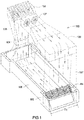
- an upright re-circulating wind tunnel 100 is shown with the air flow shown in by the arrows A.
- This type of wind tunnel is most commonly used for skydiving simulation and other human flight activities.
- Other types of re-circulating wind tunnels are well known in the art, including ones used for various types of testing.
- the present disclosure will be discussed using the upright type, it is to be understood that the disclosure includes other types of re-circulating wind tunnels.
- a common feature of all re-circulating wind tunnels is the heat generated by the friction of the air flow through the plenums.
- the re-circulating wind tunnel 100 can have a single return configuration, as shown in Figure 1 , or a multiple return configuration. See for example US Patents 6,083,110 and 7,156,744 .
- a single return re-circulating wind tunnel 100 has a first upright plenum 106 which has flight chamber 104. The air A then flows into top plenum 105, second vertical plenum 107 and then into bottom plenum 108 and back into first upright plenum 106.
- the upright plenums 106, 107 and the top plenum 105 of the wind tunnel 100 are shown dotted lines for clarity.
- the position of the fans 101 is shown for purposes of example only and not by limitation. Fans 101 in other positions well known in the art could be used as well and are considered within the scope of this disclosure.
- a heat exchanger turning vane assembly 200 is in end 109 of the bottom plenum 108. Other locations could be used as well depending on the particular application. More than one heat exchanger turning vane assembly 200 could also be used depending on the particular application. In many instances, a second heat exchanger turning vane assembly would be located below the flight chamber 104, due to the lower cost of installing the assembly on the ground. However, if needed in a particular installation, the assembly could be installed in the top plenum 105 corners.
- Standard turning vane assemblies 102 can be used at the corners where no heat exchanger turning vane assembly 200 is installed to smoothly change the direction of the airflow with minimum turbulence.
- a turning vane assembly 102 is shown above the flight chamber 104 at the transition from the first vertical plenum to the top plenum 105 as an example.
- the other turning vanes have not been included to simplify the drawings, but may be used in normal operation of the re-circulating wind tunnel as a human flight simulator.
- end 109 of the bottom air plenum 108 has a larger width D2 than the width of the bottom air plenum D1 to allow the plumbing of the heat exchanger turning vane 200 to be out of the main flow path to reduce air turbulence but this is not essential.
- the plumbing at the end of the vanes can remain in the airflow.
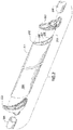
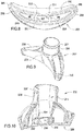
- FIG 2 is an exploded view of a single heat exchanger turning vane 201 with two plumbing connection pieces 202, one at each end to connect to standard plumbing pipe with a common chemical bond or via a standard flexible hose 204 held in place with standard hose clamps.
- the hose 204 is made of rubber, but other flexible materials could be used as well.
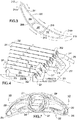
- Figure 3 is an end view of heat exchanger turning vane 201.
- the outer surface 205 is configured according to well known aerodynamic principles in a curved airfoil shape to smoothly change the direction of the airflow. Arrows A indicate the airflow over the heat exchanger turning vane 201. In the depicted example, the airflow would change direction by 90 degrees. If desired, other amounts of change of direction could be achieved.
- the heat exchanger turning vane 201 has a substantially continuous interior configuration and substantially constant cross section in the depicted embodiment, such that the end view would also be a cross sectional view at any point along its length.
- the heat exchanger turning vane 201 is made by extrusion molding of aluminum in the depicted example. Other materials with similar properties of good thermal exchange and sufficient rigidity could be used as well.
- the heat exchanger turning vane 201 is hollow to reduce the amount of material required and to allow for fluid to flow through the length of the heat exchanger turning vane 201 such that the fluid functions as a heat transfer medium.
- the thickness of the outer wall 211 is a balance between being thick enough to provide sufficient rigidity to the turning vane 201 and thin enough to allow good thermal exchange between the heat transfer medium flowing inside the vane and the air flowing over the outside of the vane. The air flowing over the surface 205 is thereby cooled as the heat is transferred into the fluid flowing inside the vane 201.
- water is used as the cooling fluid due to its ready availability and lack of toxicity.
- This also allows the fluid heated by the heat exchange to be used to easily transport the heat to other locations or for other purposes for which water would normally be heated by standard heating devices. Examples include, but are not limited to domestic hot water use, swimming pools or aquariums and other uses as will be discussed further below.
- Other, known in the art heat transfer mediums could be used as well, including, but not limited to, Freon gas, salt water, compressed gasses and other refrigerants.
- the length of the turning vane 201 can vary depending on the application. Vanes as long as 65 feet or longer can be used in large installations.
- Bracing members 209, 210 divide the interior space of the heat exchanger turning vane 201 into channels. The bracing members 209 and 210 are to ensure the heat exchanger turning vane 201 has sufficient rigidity to withstand the airflow and the weight of the fluid flowing through in use without bending. The bracing members 209, 210 also increase the surface area of the turning vane 201 that is in contact with the fluid, increasing the speed and efficiency of the heat transfer to the fluid. In the depicted embodiment there are three channels 206, 207 and 208.
- More or less channels and bracing members could be used depending on the size of the heat exchanger turning vane 201 and the volume of fluid flow desired.
- all of the fluid in a turning vane would be flowing in the same direction, regardless of how many channels the interior of the vane is divided into for structural reasons.
- the heat exchanging capacity depends on the surface area of the contact between the fluid and the turning vane 201, the thermal resistance of the material of the heat exchanger turning vane 201, the thermal resistance and flow rate of the fluid and the difference in temperature between the cooling fluid and the airflow. For any given turning vane 201 in any given installation, these factors will all need to be optimized to ensure sufficient cooling of the airflow occurs.
- the majority of the area of the cross section of the turning vane 201 is fluid flow space, as seen in Figure 3 .
- screw bosses 214a, 214b are formed into the interior of the heat exchanger turning vane 201. These screw bosses 214a, 214b allow the turning vane 201 to be attached to a flange or other surface perpendicular to the direction of flow of the fluid in the vane. This method of attachment makes the assembly of turning vane assemblies 200 faster, easier and less expensive. Since the screw bosses can be formed into the extrusion mold for the turning vane 201, the turning vane 201 can be extruded to any length and then attached as needed with no further modification needed.
- screw bosses 214a, 214b could be formed by leaving the area of the screw bosses solid in the extruded part and drilling out holes and possibly tapping threads after extrusion to form screw bosses 214a, 214b.
- screw attachments could be installed into the interior of or on the exterior of the turning vane after formation of the turning vane, such as by welding, epoxy or other means.
- connection piece 202 In a heat exchanger turning vane assembly 200 it is necessary that the attachment of the turning vane 201 to the connection piece 202 be largely fluid tight, to allow for continuous flow of fluid, often under pressure. Depending on the application and the heat exchange medium being used, some low levels of leakage of exchange medium may be acceptable. Therefore the term fluid tight should be understood to encompass levels of fluid leakage at the junctions that are within operating tolerances. However, even once the screw bosses 214a, 214b are formed into interior of the turning vane 201, a connection piece that allows for a fluid tight connection that is easy to assemble and is not expensive to manufacture is needed. Large numbers of these connection pieces are needed, as will be discussed below.
- the greatest need for heat exchangers in re-circulating wind tunnels is in those used for amusement attractions and training facilities, which are often operated near continuously or at least for extended operating hours, unlike testing tunnels.
- the cost and time to build the tunnel become a critical factor in the profitability of the business or viability of the project, while the need to keep the air at a comfortable temperature for paying customers and trainees increases, particularly in warmer climates.
- the heat exchanger must be easy to maintain in terms of both cost and down time, to prevent the maintenance costs of the wind tunnel from becoming excessive. Therefore the heat exchange mechanism as a whole must be low cost to build and must be able to be built, installed, inspected, tested, updated and/or replaced within reasonable time parameters. Further it is important that any needed repairs must be relatively easy and low cost to perform.
- connection pieces 202 should function to form a simple, inexpensive, fluid tight connection between the airfoil shape of the turning vane 201 and standard plumbing pipe or hose 204 in the depicted embodiment.
- the connection pieces 202 must be easy to attach and remove from the turning vane 201 ends.
- the connection pieces 202 themselves should be low cost to manufacture, in the depicted embodiment they are manufactured from a two piece injection mold, which significantly reduces the cost of individual connection pieces 202 to manufacture.
- the number and size of the turning vanes in a given heat exchanger turning vane assembly 200 needed in any particular heat exchanger application will depend on the airflow speed, heat to be exchanged, and airflow volume of a given tunnel.
- FIG 4 is a perspective view of one end of the heat exchanger turning vane assembly 200 with the turning vane 201 mounted in a rack 215.
- the rack 215 has shaped slots 216 to hold the turning vanes at the appropriate angle and orientation.
- the racks 215 are designed in such a manner that no additional mechanical connection is required to hold the smooth continuous exterior of the turning vane 201 to the rack 215.
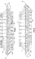
- Side views of the whole heat exchanger turning vane assembly 200 can be seen in Figures 5 and 6 .
- the horizontal floor of the bottom plenum 108 is indicated by line F.
- the racks 215 have been shown in a rotated manner for easy of viewing. This should not be taken to indicate that the racks 215 would be mounted in the orientation shown in the Figures 5 and 6 .
- the appropriate orientation of the rack 215 and the heat exchanger turning vane assembly 200 is also shown in Figure 1 .
- the inflowing cold water flows through four turning vanes 201 before being carried away from the heat exchanger turning vane assembly 200 as warm water.
- the cold water flows in through inflow pipe 217 and is connected to pipe or rubber hose 204 which is connected to connection piece 202 and thence to the turning vane 201, labeled A in Figure 4 .
- the labels A, B, C and D are purely to indicate the turning vanes 201 being discussed in the flow path to aid the reader in understanding the flow path of the depicted embodiment. These turning vanes 201 are not different from any of the other turning vanes 201 discussed herein. This configuration of flowing through four turning vanes is repeated with the remaining turning vanes 201.
- the inflow pipes 217 are connected to cold water supply pipe 220 and the outflow pipes are connected to warm water removal pipe 221.
- the warm water can be used to heat any desired nearby location, either by flowing the warm water directly into a water supply line for pool or other location needing warm water, or by having a second heat exchanger on the other end of the line, allowing the heat to be pulled out the water at the desired location.
- a heating system for the building could be flowed into a heating system for the building and the heat used to heat the building using standard warm water heat exchange systems.
- the now cooled water could be flowed back to the heat exchanger turning vane assembly 200 to the cold water supply pipe 220, forming a largely closed loop.
- the flowing of the water through four turning vanes 201 in the depicted embodiment should not be taken as a limitation, fewer passes through turning vanes 201 or more passes though turning vanes 201 could be used, depending on the application and the cooling needs of any particular installation. As mentioned above, other cooling mediums could be used as well as water in a given installation. No limitation to a particular cooling medium is intended or should be implied.
- connection piece 202 is in Figures 7 , 8, 9 and 10 .
- Connection piece 202 has a body 235, a pipe connection piece 236 and a bottom surface 233.
- the body 235 has an outer ridge 228 which adds rigidity to the connection piece and gives it the proper aerodynamic shape.
- the rounded edges of the connection piece 202 are for structural and aesthetic reasons. The edges could be square or other configurations as desired.
- the pipe connection piece 236 has ring 237 extending annularly from its surface to allow standard hose clamps to attach a standard flexible hose to the adjacent connection pipe. If desired, a connection pipe could be attached directly to the pipe connection pieces 236 instead of having a flexible hose piece between them.
- the flexible hose piece allows for flex in the turning vanes 201 caused by the fluid flow or other forces to be absorbed without causing stress on the fluid pipes.
- Screw holes 230, 231 that align with screw bosses 214a, 214b respectively on turning vane 201.
- Screw holes 230 are located near ends 245, 246 of the body 235 and align with screw bosses 214a.
- Screw holes 231 align with screw bosses 214b and are located on cross members 239, 240, which correspond in location and general shape to bracing members 209, 210.
- Cross members 239, 240 only extend a limited height H into the interior 241 as seen in Figure 10 . This leaves the majority of the interior 241 of the connection piece 202 open to allow for maximum fluid flow.
- the cross members 239, 240 need to be sufficiently rigid to hold the screws when the connection piece is held fluid tight against the turning vane 201.
- the exact height H of the cross members 239, 240 will depend on the specific application.
- the cross members 239, 240 divide the bottom surface 233 to form three openings 242, 243, 244 that correspond to channels 206, 207 and 208 in the turning vane 201. This allows the fluid to flow out of the interior of the turning vane and into the interior 241 of the connection piece 202 and then into the pipes and vice versa.
- the fluid flow from the pipes 217 into the connection piece is split into the channels 206, 207 and 208 through the connection piece 202. If a gaseous cooling medium is used, then gas tight connections will be needed, which can be provided with the appropriate sealing means.
- All four screw holes 230, 231 are accessible from the top side of the connection piece 202, as can be seen in Figure 7 . This allows an installer or repair person to attach or remove the connection piece 202 easily and quickly with common tools.
- the screw holes 231 that attach to the screw bosses 214b on the bracing members 209, 210 are required to ensure a water tight seal. Screw holes 231 are located within the flow area of the connection piece 201 so that any leak at the screw head would be inconsequential. This means that only the other two screw 230 locations require a gasket or o-ring to prevent or reduce leakage of the fluid from under the screw head. One gasket is used per screw location.
- connection piece 201 corresponds to the shape of the end of turning vane 201, so that the connection piece 201 sets over the end of turning vane 201 to allow a water tight seal to be formed.
- a sealing gasket (not shown) fits in recess 232 and is shaped to correspond to the bottom of connection pieces 201. The sealing gasket is die-cut from a sheet of EPDM rubber in the depicted embodiment.
- Part of the shape of the recess 232 is designed to hold the sealing gasket in place while the connection piece is being attached to the turning vane. If a gaseous cooling medium is used, then gas tight connections will be needed, which can be provided with the appropriate sealing gaskets and sufficiently tighten screws. If needed the size of the screw holes can be different at each location.
- connection piece 202 in the depicted embodiment allows the connection piece to be formed in a two piece injection mold, allowing the connection pieces 202 to be manufactured at low cost.
- connection piece is made out of ABS Plastic but it may also be made from polycarbonate, polypropelene, polyvinyl chloride (PVC), nylon and other forms of plastic.
- the method can further comprise using the heat removed in the first system to be transported to another system and used to heat another system.
- the method can further comprise returning the now cooled water to the first system.
Priority Applications (1)
| Application Number | Priority Date | Filing Date | Title |
|---|---|---|---|
| PL18169754T PL3382364T3 (pl) | 2010-01-15 | 2011-01-15 | Sposób stosowania wielu wydrążonych, obrotowych łopatek kierujących w tunelu aerodynamicznym |
Applications Claiming Priority (3)
| Application Number | Priority Date | Filing Date | Title |
|---|---|---|---|
| US29522910P | 2010-01-15 | 2010-01-15 | |
| PCT/US2011/021437 WO2011088426A1 (en) | 2010-01-15 | 2011-01-15 | Wind tunnel turning vane heat exchanger |
| EP11702317.6A EP2524199B1 (en) | 2010-01-15 | 2011-01-15 | Wind tunnel turning vane heat exchanger |
Related Parent Applications (1)
| Application Number | Title | Priority Date | Filing Date |
|---|---|---|---|
| EP11702317.6A Division EP2524199B1 (en) | 2010-01-15 | 2011-01-15 | Wind tunnel turning vane heat exchanger |
Publications (2)
| Publication Number | Publication Date |
|---|---|
| EP3382364A1 EP3382364A1 (en) | 2018-10-03 |
| EP3382364B1 true EP3382364B1 (en) | 2020-06-10 |
Family
ID=43608838
Family Applications (2)
| Application Number | Title | Priority Date | Filing Date |
|---|---|---|---|
| EP18169754.1A Active EP3382364B1 (en) | 2010-01-15 | 2011-01-15 | Method for use of a plurality of hollow turning vanes in a wind tunnel |
| EP11702317.6A Active EP2524199B1 (en) | 2010-01-15 | 2011-01-15 | Wind tunnel turning vane heat exchanger |
Family Applications After (1)
| Application Number | Title | Priority Date | Filing Date |
|---|---|---|---|
| EP11702317.6A Active EP2524199B1 (en) | 2010-01-15 | 2011-01-15 | Wind tunnel turning vane heat exchanger |
Country Status (24)
| Country | Link |
|---|---|
| US (3) | US9194632B2 (ko) |
| EP (2) | EP3382364B1 (ko) |
| KR (4) | KR102064138B1 (ko) |
| CN (2) | CN102741675B (ko) |
| AU (1) | AU2011205659B2 (ko) |
| BR (1) | BR112012017557B1 (ko) |
| CL (1) | CL2012001962A1 (ko) |
| CY (1) | CY1120376T1 (ko) |
| DK (2) | DK2524199T3 (ko) |
| ES (2) | ES2668205T3 (ko) |
| HK (2) | HK1174382A1 (ko) |
| HR (1) | HRP20180849T1 (ko) |
| HU (1) | HUE037296T2 (ko) |
| IL (1) | IL220929A (ko) |
| LT (1) | LT2524199T (ko) |
| MY (1) | MY161573A (ko) |
| NO (1) | NO2524199T3 (ko) |
| PL (2) | PL3382364T3 (ko) |
| PT (1) | PT2524199T (ko) |
| RU (1) | RU2012134773A (ko) |
| SG (3) | SG10201500196XA (ko) |
| SI (1) | SI2524199T1 (ko) |
| WO (1) | WO2011088426A1 (ko) |
| ZA (1) | ZA201206046B (ko) |
Families Citing this family (15)
| Publication number | Priority date | Publication date | Assignee | Title |
|---|---|---|---|---|
| PL3382364T3 (pl) | 2010-01-15 | 2020-11-30 | Skyventure International (Uk) Ltd. | Sposób stosowania wielu wydrążonych, obrotowych łopatek kierujących w tunelu aerodynamicznym |
| GB201404445D0 (en) * | 2014-03-13 | 2014-04-30 | Bae Systems Plc | Heat exchanger |
| US9702630B2 (en) | 2014-03-13 | 2017-07-11 | Bae Systems Plc | Heat exchanger |
| EP3431950A1 (de) * | 2014-06-04 | 2019-01-23 | Indoor Skydiving Germany GmbH | Luftumlenkeinrichtung |
| US9327202B2 (en) | 2014-06-30 | 2016-05-03 | Airborne America, Inc. | Wind tunnel design with expanding corners |
| USD770383S1 (en) | 2014-07-28 | 2016-11-01 | Black Swan Equity Llc | Wind tunnel |
| JP2016202523A (ja) * | 2015-04-22 | 2016-12-08 | ルスラン ロマネンコ | スカイダイビングシミュレータ |
| WO2016170365A2 (en) | 2015-04-22 | 2016-10-27 | Romanenko Ruslan | Vertical wind tunnel skydiving simulator |
| ITUB20160133A1 (it) * | 2016-01-14 | 2017-07-14 | Extreme Flight Fze | Dispositivo di raffreddamento per una galleria del vento a flusso circolante, in particolare per effettuare simulazioni di caduta libera o paracadutismo. |
| US10821509B2 (en) | 2016-01-20 | 2020-11-03 | General Electric Company | Additive heat exchanger mixing chambers |
| SG11202103489QA (en) | 2018-11-16 | 2021-05-28 | Skyventure Int Uk Ltd | Recirculating vertical wind tunnel |
| CN110823501B (zh) * | 2019-11-15 | 2024-03-19 | 中国空气动力研究与发展中心超高速空气动力研究所 | 一种用于高超声速低密度风洞稳定段的水冷光学测试法兰 |
| CN112729786A (zh) * | 2020-12-18 | 2021-04-30 | 成都成发泰达航空科技有限公司 | 航空发动机叶片寿命的测试系统、装置及其方法 |
| CN113550827A (zh) * | 2021-08-04 | 2021-10-26 | 哈尔滨工业大学 | 一种扇形叶栅叶片及其角度安装方法 |
| CN114329839A (zh) * | 2021-12-31 | 2022-04-12 | 北京卫星环境工程研究所 | 一种用于平流层环境模拟的电机系统 |
Citations (4)
| Publication number | Priority date | Publication date | Assignee | Title |
|---|---|---|---|---|
| DE482902C (de) | 1927-05-05 | 1929-09-24 | Versuchsanstalt Fuer Luftfahrt | Windkanalanlage mit Mitteln zur AEnderung der Temperatur des Luftstromes |
| GB1108505A (en) | 1965-08-19 | 1968-04-03 | Eaton Yale & Towne | Heat exchanger |
| US4993485A (en) | 1989-09-18 | 1991-02-19 | Gorman Jeremy W | Easily disassembled heat exchanger of high efficiency |
| EP1327847A1 (en) | 2002-01-15 | 2003-07-16 | Modine Manufacturing Company | Tank and cap assembly for use with microchannel tubing in a heat exchanger |
Family Cites Families (57)
| Publication number | Priority date | Publication date | Assignee | Title |
|---|---|---|---|---|
| US884326A (en) * | 1907-06-17 | 1908-04-07 | Mellen N Bray | Means for distributing water to water-jackets of multiple-cylinder engines. |
| NL92675C (ko) | 1954-04-27 | |||
| US2788020A (en) | 1954-09-16 | 1957-04-09 | North American Aviation Inc | Wind tunnel nozzle adjustment linkage |
| DE1077410B (de) | 1954-10-13 | 1960-03-10 | Gerhard Goebel Dipl Ing | Konvektor |
| US2930579A (en) * | 1955-09-19 | 1960-03-29 | Dominion Eng Works Ltd | Turbine guide vane locking and vibration preventing arrangement |
| US2937890A (en) | 1955-12-21 | 1960-05-24 | Alco Products Inc | Pipe coupling for heat exchangers |
| US2991982A (en) * | 1957-09-12 | 1961-07-11 | Sigurd O Johnson | Centrifugal fluid moving device |
| US3381713A (en) * | 1965-10-14 | 1968-05-07 | Gordon R. Jacobsen | Turning vane and rail construction |
| US3369792A (en) | 1966-04-07 | 1968-02-20 | Gen Electric | Airfoil vane |
| US3367628A (en) * | 1966-10-31 | 1968-02-06 | United Aircraft Corp | Movable vane unit |
| US3566823A (en) * | 1967-11-07 | 1971-03-02 | Charles Davis Hope Gill | Power plant |
| US3558237A (en) * | 1969-06-25 | 1971-01-26 | Gen Motors Corp | Variable turbine nozzles |
| DE2441990A1 (de) * | 1974-09-02 | 1976-03-11 | Erbsloeh Julius & August | Rohrregisterheizkoerper aus stranggepressten heizkoerpergliedern |
| US4082325A (en) * | 1976-05-05 | 1978-04-04 | Tenneco Inc. | Coupling device for connecting a plurality of ports to one pipe |
| CH609142A5 (en) * | 1976-09-22 | 1979-02-15 | Edak Ag | Sun-screening lamella |
| JPS63204129A (ja) | 1987-02-19 | 1988-08-23 | Mitsubishi Heavy Ind Ltd | 回流型風洞 |
| GB2210935B (en) * | 1987-10-10 | 1992-05-27 | Rolls Royce Plc | Variable stator vane assembly |
| JPH03131289A (ja) | 1989-10-17 | 1991-06-04 | Toda Constr Co Ltd | レジャー施設 |
| JP3131289B2 (ja) | 1992-05-29 | 2001-01-31 | 東芝テック株式会社 | 商品販売登録処理装置 |
| US5407321A (en) * | 1993-11-29 | 1995-04-18 | United Technologies Corporation | Damping means for hollow stator vane airfoils |
| US5495754A (en) | 1994-01-04 | 1996-03-05 | Sverdrup Technology, Inc. | Environmental wind tunnel |
| CN2197611Y (zh) * | 1994-02-05 | 1995-05-17 | 魏厚健 | 一种夹壁式空调器 |
| US5625947A (en) * | 1995-03-08 | 1997-05-06 | Kimball Physics, Inc. | Method for forming a vacuum port manifold |
| DE19511514C1 (de) * | 1995-03-29 | 1996-08-01 | Daimler Benz Ag | Abgaskrümmer für eine Brennkraftmaschine |
| US5734202A (en) | 1995-07-27 | 1998-03-31 | Shuler; Melvin B. | Method and apparatus for generating electricity utilizing a forced recirculating air tunnel |
| US5722241A (en) | 1996-02-26 | 1998-03-03 | Westinghouse Electric Corporation | Integrally intercooled axial compressor and its application to power plants |
| CN2271210Y (zh) * | 1996-10-31 | 1997-12-24 | 王兴发 | 储能热交换器 |
| JP2948199B2 (ja) * | 1997-09-22 | 1999-09-13 | 通彦 川野 | 案内羽根入り吸込エルボ |
| US5861585A (en) * | 1997-09-30 | 1999-01-19 | Aiolos Engineering Corporation | Aeracoustic wind tunnel turning vanes |
| JP3817063B2 (ja) | 1998-04-20 | 2006-08-30 | 大成建設株式会社 | 建物用ルーバ |
| USRE43028E1 (en) | 1998-09-23 | 2011-12-13 | Skyventure, Llc | Vertical wind tunnel training device |
| US6083110A (en) | 1998-09-23 | 2000-07-04 | Sky Venture, Inc. | Vertical wind tunnel training device |
| US6725912B1 (en) | 1999-05-21 | 2004-04-27 | Aero Systems Engineering, Inc. | Wind tunnel and heat exchanger therefor |
| DE19943307B4 (de) * | 1999-09-10 | 2010-09-30 | Hansgrohe Ag | Schutzeinrichtung für Sanitärarmaturen |
| US6478340B1 (en) * | 2000-03-30 | 2002-11-12 | Boyd L. Butler | Y-pipe for thin boom tube exhaust pipes providing increased ground clearance on race cars |
| DE10142979C1 (de) * | 2001-09-01 | 2003-05-28 | Porsche Ag | Abgaskrümmer einer Abgasanlage für eine Brennkraftmaschine |
| DE20209893U1 (de) | 2002-06-26 | 2002-10-17 | Grychtolik Alexander | Lamellen-Sonnenkollektor |
| AU2003263867A1 (en) | 2002-08-20 | 2004-04-08 | Aero Systems Engineering Inc. | Free fall simulator |
| CN100526785C (zh) * | 2003-11-27 | 2009-08-12 | 邹占武 | 可调控自然风场空冷系统 |
| US7156744B2 (en) | 2004-07-30 | 2007-01-02 | Skyventure, Llc | Recirculating vertical wind tunnel skydiving simulator |
| US7028542B2 (en) | 2004-07-30 | 2006-04-18 | Metni N Alan | Reduced drag cable for use in wind tunnels and other locations |
| CN2903891Y (zh) * | 2006-06-08 | 2007-05-23 | 陶建中 | 具清洁装置的热交换器 |
| WO2008015583A1 (en) * | 2006-06-13 | 2008-02-07 | Wescast Industries, Inc. | Exhaust manifolds including heat shield assemblies |
| EP1980705A1 (en) | 2007-04-11 | 2008-10-15 | Oranjedak B.V. | Building comprising a heat exchanger and a sunblind |
| JP4918392B2 (ja) * | 2007-04-19 | 2012-04-18 | 株式会社ユタカ技研 | 多気筒エンジンの排気集合部 |
| US20080277095A1 (en) | 2007-05-07 | 2008-11-13 | Kelvin Zhai | Heat exchanger assembly |
| US8202043B2 (en) * | 2007-10-15 | 2012-06-19 | United Technologies Corp. | Gas turbine engines and related systems involving variable vanes |
| KR20080071543A (ko) * | 2008-07-15 | 2008-08-04 | 최의영 | 플렌지 접합 이음쇠 |
| US20120048953A1 (en) | 2009-07-15 | 2012-03-01 | Beihang University | Temperature adjusting device and an intelligent temperature control method for a sand and dust environment testing system |
| CN101639397B (zh) | 2009-07-15 | 2011-05-18 | 北京航空航天大学 | 一体式吹砂吹尘环境模拟系统的温度调节系统和方法 |
| CZ20638U1 (cs) | 2009-10-12 | 2010-03-15 | Strojírna Litvínov spol. s r.o. | Simulátor volného pádu |
| PL3382364T3 (pl) | 2010-01-15 | 2020-11-30 | Skyventure International (Uk) Ltd. | Sposób stosowania wielu wydrążonych, obrotowych łopatek kierujących w tunelu aerodynamicznym |
| EP2386285A1 (en) * | 2010-05-10 | 2011-11-16 | B. Braun Melsungen AG | Port device |
| US20120068452A1 (en) * | 2010-09-22 | 2012-03-22 | Cleveland Tubing, Inc. | Low Profile Collapsible, Expandable, Flexible and Camouflaged Corrugated Downspout Extension and Adapter |
| EP2511084B1 (de) * | 2011-04-14 | 2014-11-12 | Magna Steyr Fahrzeugtechnik AG & Co KG | Knotenelement aus faserverstärktem Kunststoff sowie Herstellungsverfahren und Verwendung dafür |
| DE102012204139A1 (de) * | 2012-03-16 | 2013-09-19 | Hansgrohe Se | Armaturengrundkörper für Sanitärarmatur |
| GB2531431B (en) * | 2013-07-24 | 2016-11-02 | Dyson Technology Ltd | An attachment for a handheld appliance |
-
2011
- 2011-01-15 PL PL18169754T patent/PL3382364T3/pl unknown
- 2011-01-15 KR KR1020197001246A patent/KR102064138B1/ko active IP Right Grant
- 2011-01-15 DK DK11702317.6T patent/DK2524199T3/en active
- 2011-01-15 EP EP18169754.1A patent/EP3382364B1/en active Active
- 2011-01-15 WO PCT/US2011/021437 patent/WO2011088426A1/en active Application Filing
- 2011-01-15 SG SG10201500196XA patent/SG10201500196XA/en unknown
- 2011-01-15 SG SG10201610108RA patent/SG10201610108RA/en unknown
- 2011-01-15 LT LTEP11702317.6T patent/LT2524199T/lt unknown
- 2011-01-15 AU AU2011205659A patent/AU2011205659B2/en active Active
- 2011-01-15 EP EP11702317.6A patent/EP2524199B1/en active Active
- 2011-01-15 SI SI201131490T patent/SI2524199T1/en unknown
- 2011-01-15 SG SG2012052007A patent/SG182525A1/en unknown
- 2011-01-15 PT PT117023176T patent/PT2524199T/pt unknown
- 2011-01-15 PL PL11702317T patent/PL2524199T3/pl unknown
- 2011-01-15 ES ES11702317.6T patent/ES2668205T3/es active Active
- 2011-01-15 BR BR112012017557-2A patent/BR112012017557B1/pt active IP Right Grant
- 2011-01-15 CN CN201180006247.9A patent/CN102741675B/zh active Active
- 2011-01-15 NO NO11702317A patent/NO2524199T3/no unknown
- 2011-01-15 CN CN201510857504.XA patent/CN105509993B/zh active Active
- 2011-01-15 KR KR1020127020469A patent/KR101810706B1/ko active IP Right Grant
- 2011-01-15 HU HUE11702317A patent/HUE037296T2/hu unknown
- 2011-01-15 US US13/520,616 patent/US9194632B2/en active Active
- 2011-01-15 KR KR1020187001389A patent/KR101940192B1/ko active IP Right Grant
- 2011-01-15 DK DK18169754.1T patent/DK3382364T3/da active
- 2011-01-15 ES ES18169754T patent/ES2817579T3/es active Active
- 2011-01-15 MY MYPI2012003091A patent/MY161573A/en unknown
- 2011-01-15 RU RU2012134773/28A patent/RU2012134773A/ru unknown
- 2011-01-15 KR KR1020177022988A patent/KR101940198B1/ko active IP Right Grant
-
2012
- 2012-07-12 IL IL220929A patent/IL220929A/en not_active IP Right Cessation
- 2012-07-13 CL CL2012001962A patent/CL2012001962A1/es unknown
- 2012-08-13 ZA ZA2012/06046A patent/ZA201206046B/en unknown
-
2013
- 2013-01-29 HK HK13101237.6A patent/HK1174382A1/zh unknown
-
2015
- 2015-11-16 US US14/942,086 patent/US20160069773A1/en not_active Abandoned
-
2016
- 2016-05-04 HK HK16105046.5A patent/HK1217040A1/zh unknown
-
2018
- 2018-05-28 HR HRP20180849TT patent/HRP20180849T1/hr unknown
- 2018-07-03 CY CY20181100692T patent/CY1120376T1/el unknown
-
2021
- 2021-06-29 US US17/362,336 patent/US11852566B2/en active Active
Patent Citations (4)
| Publication number | Priority date | Publication date | Assignee | Title |
|---|---|---|---|---|
| DE482902C (de) | 1927-05-05 | 1929-09-24 | Versuchsanstalt Fuer Luftfahrt | Windkanalanlage mit Mitteln zur AEnderung der Temperatur des Luftstromes |
| GB1108505A (en) | 1965-08-19 | 1968-04-03 | Eaton Yale & Towne | Heat exchanger |
| US4993485A (en) | 1989-09-18 | 1991-02-19 | Gorman Jeremy W | Easily disassembled heat exchanger of high efficiency |
| EP1327847A1 (en) | 2002-01-15 | 2003-07-16 | Modine Manufacturing Company | Tank and cap assembly for use with microchannel tubing in a heat exchanger |
Also Published As
Similar Documents
| Publication | Publication Date | Title |
|---|---|---|
| US11852566B2 (en) | Wind tunnel turning vane heat exchanger | |
| CN110087443A (zh) | 利用集成的精密空气流动的计算机服务器 | |
| CN105167241A (zh) | 一种个人冷却系统 | |
| US8955509B2 (en) | Solar water heating systems and methods of making and using the same | |
| CN204968337U (zh) | 一种空调柜及具有其的服务器机柜系统 | |
| CN202361843U (zh) | 闭式冷却塔 | |
| CN105228415A (zh) | 一种空调柜及具有其的服务器机柜系统 | |
| WO2019205418A1 (zh) | 可双向安装的竖向壁挂空调室内机 | |
| CN211526756U (zh) | 一种不共风v型风冷模块机组外框 | |
| CN205091662U (zh) | 模块化数据中心 | |
| CN104951017A (zh) | 模块化数据中心 | |
| CN212645413U (zh) | 永磁直驱冷却塔 | |
| CN103437964A (zh) | 风力发电机组机舱冷却用换热器 | |
| CN203430710U (zh) | 风力发电机组机舱冷却用换热器 | |
| CN219180606U (zh) | 液冷管道和储能装置 | |
| CN208952291U (zh) | 模块化冷冻水空调 | |
| CN109520009A (zh) | 一种立式采暖器 | |
| CN105555104A (zh) | 一种机房排热用顶置热管模块结构 | |
| CN205561177U (zh) | 一种结构紧凑分体式空调末端设备冷墙 | |
| CN203869235U (zh) | 一种灾备系统专用的机房空调装置 | |
| CN104075592A (zh) | 一种带有导向流道结构的空气冷却器 |
Legal Events
| Date | Code | Title | Description |
|---|---|---|---|
| PUAI | Public reference made under article 153(3) epc to a published international application that has entered the european phase |
Free format text: ORIGINAL CODE: 0009012 |
|
| STAA | Information on the status of an ep patent application or granted ep patent |
Free format text: STATUS: THE APPLICATION HAS BEEN PUBLISHED |
|
| AC | Divisional application: reference to earlier application |
Ref document number: 2524199 Country of ref document: EP Kind code of ref document: P |
|
| AK | Designated contracting states |
Kind code of ref document: A1 Designated state(s): AL AT BE BG CH CY CZ DE DK EE ES FI FR GB GR HR HU IE IS IT LI LT LU LV MC MK MT NL NO PL PT RO RS SE SI SK SM TR |
|
| STAA | Information on the status of an ep patent application or granted ep patent |
Free format text: STATUS: REQUEST FOR EXAMINATION WAS MADE |
|
| 17P | Request for examination filed |
Effective date: 20190401 |
|
| RBV | Designated contracting states (corrected) |
Designated state(s): AL AT BE BG CH CY CZ DE DK EE ES FI FR GB GR HR HU IE IS IT LI LT LU LV MC MK MT NL NO PL PT RO RS SE SI SK SM TR |
|
| GRAP | Despatch of communication of intention to grant a patent |
Free format text: ORIGINAL CODE: EPIDOSNIGR1 |
|
| STAA | Information on the status of an ep patent application or granted ep patent |
Free format text: STATUS: GRANT OF PATENT IS INTENDED |
|
| RIC1 | Information provided on ipc code assigned before grant |
Ipc: B64D 23/00 20060101ALI20191205BHEP Ipc: F28F 1/02 20060101ALI20191205BHEP Ipc: F28F 9/06 20060101ALI20191205BHEP Ipc: F28F 9/02 20060101ALI20191205BHEP Ipc: F28F 9/26 20060101ALI20191205BHEP Ipc: G01M 9/04 20060101AFI20191205BHEP Ipc: A63G 31/00 20060101ALI20191205BHEP |
|
| INTG | Intention to grant announced |
Effective date: 20200103 |
|
| GRAS | Grant fee paid |
Free format text: ORIGINAL CODE: EPIDOSNIGR3 |
|
| GRAA | (expected) grant |
Free format text: ORIGINAL CODE: 0009210 |
|
| STAA | Information on the status of an ep patent application or granted ep patent |
Free format text: STATUS: THE PATENT HAS BEEN GRANTED |
|
| AC | Divisional application: reference to earlier application |
Ref document number: 2524199 Country of ref document: EP Kind code of ref document: P |
|
| AK | Designated contracting states |
Kind code of ref document: B1 Designated state(s): AL AT BE BG CH CY CZ DE DK EE ES FI FR GB GR HR HU IE IS IT LI LT LU LV MC MK MT NL NO PL PT RO RS SE SI SK SM TR |
|
| REG | Reference to a national code |
Ref country code: GB Ref legal event code: FG4D |
|
| REG | Reference to a national code |
Ref country code: AT Ref legal event code: REF Ref document number: 1279571 Country of ref document: AT Kind code of ref document: T Effective date: 20200615 Ref country code: CH Ref legal event code: EP |
|
| REG | Reference to a national code |
Ref country code: DE Ref legal event code: R096 Ref document number: 602011067309 Country of ref document: DE |
|
| REG | Reference to a national code |
Ref country code: IE Ref legal event code: FG4D |
|
| REG | Reference to a national code |
Ref country code: DK Ref legal event code: T3 Effective date: 20200903 |
|
| REG | Reference to a national code |
Ref country code: LT Ref legal event code: MG4D |
|
| PG25 | Lapsed in a contracting state [announced via postgrant information from national office to epo] |
Ref country code: NO Free format text: LAPSE BECAUSE OF FAILURE TO SUBMIT A TRANSLATION OF THE DESCRIPTION OR TO PAY THE FEE WITHIN THE PRESCRIBED TIME-LIMIT Effective date: 20200910 Ref country code: GR Free format text: LAPSE BECAUSE OF FAILURE TO SUBMIT A TRANSLATION OF THE DESCRIPTION OR TO PAY THE FEE WITHIN THE PRESCRIBED TIME-LIMIT Effective date: 20200911 Ref country code: FI Free format text: LAPSE BECAUSE OF FAILURE TO SUBMIT A TRANSLATION OF THE DESCRIPTION OR TO PAY THE FEE WITHIN THE PRESCRIBED TIME-LIMIT Effective date: 20200610 Ref country code: LT Free format text: LAPSE BECAUSE OF FAILURE TO SUBMIT A TRANSLATION OF THE DESCRIPTION OR TO PAY THE FEE WITHIN THE PRESCRIBED TIME-LIMIT Effective date: 20200610 Ref country code: SE Free format text: LAPSE BECAUSE OF FAILURE TO SUBMIT A TRANSLATION OF THE DESCRIPTION OR TO PAY THE FEE WITHIN THE PRESCRIBED TIME-LIMIT Effective date: 20200610 |
|
| REG | Reference to a national code |
Ref country code: NL Ref legal event code: MP Effective date: 20200610 |
|
| PG25 | Lapsed in a contracting state [announced via postgrant information from national office to epo] |
Ref country code: LV Free format text: LAPSE BECAUSE OF FAILURE TO SUBMIT A TRANSLATION OF THE DESCRIPTION OR TO PAY THE FEE WITHIN THE PRESCRIBED TIME-LIMIT Effective date: 20200610 Ref country code: HR Free format text: LAPSE BECAUSE OF FAILURE TO SUBMIT A TRANSLATION OF THE DESCRIPTION OR TO PAY THE FEE WITHIN THE PRESCRIBED TIME-LIMIT Effective date: 20200610 Ref country code: BG Free format text: LAPSE BECAUSE OF FAILURE TO SUBMIT A TRANSLATION OF THE DESCRIPTION OR TO PAY THE FEE WITHIN THE PRESCRIBED TIME-LIMIT Effective date: 20200910 Ref country code: RS Free format text: LAPSE BECAUSE OF FAILURE TO SUBMIT A TRANSLATION OF THE DESCRIPTION OR TO PAY THE FEE WITHIN THE PRESCRIBED TIME-LIMIT Effective date: 20200610 |
|
| REG | Reference to a national code |
Ref country code: AT Ref legal event code: MK05 Ref document number: 1279571 Country of ref document: AT Kind code of ref document: T Effective date: 20200610 |
|
| PG25 | Lapsed in a contracting state [announced via postgrant information from national office to epo] |
Ref country code: AL Free format text: LAPSE BECAUSE OF FAILURE TO SUBMIT A TRANSLATION OF THE DESCRIPTION OR TO PAY THE FEE WITHIN THE PRESCRIBED TIME-LIMIT Effective date: 20200610 Ref country code: NL Free format text: LAPSE BECAUSE OF FAILURE TO SUBMIT A TRANSLATION OF THE DESCRIPTION OR TO PAY THE FEE WITHIN THE PRESCRIBED TIME-LIMIT Effective date: 20200610 |
|
| PG25 | Lapsed in a contracting state [announced via postgrant information from national office to epo] |
Ref country code: PT Free format text: LAPSE BECAUSE OF FAILURE TO SUBMIT A TRANSLATION OF THE DESCRIPTION OR TO PAY THE FEE WITHIN THE PRESCRIBED TIME-LIMIT Effective date: 20201012 Ref country code: AT Free format text: LAPSE BECAUSE OF FAILURE TO SUBMIT A TRANSLATION OF THE DESCRIPTION OR TO PAY THE FEE WITHIN THE PRESCRIBED TIME-LIMIT Effective date: 20200610 Ref country code: CZ Free format text: LAPSE BECAUSE OF FAILURE TO SUBMIT A TRANSLATION OF THE DESCRIPTION OR TO PAY THE FEE WITHIN THE PRESCRIBED TIME-LIMIT Effective date: 20200610 Ref country code: EE Free format text: LAPSE BECAUSE OF FAILURE TO SUBMIT A TRANSLATION OF THE DESCRIPTION OR TO PAY THE FEE WITHIN THE PRESCRIBED TIME-LIMIT Effective date: 20200610 Ref country code: SM Free format text: LAPSE BECAUSE OF FAILURE TO SUBMIT A TRANSLATION OF THE DESCRIPTION OR TO PAY THE FEE WITHIN THE PRESCRIBED TIME-LIMIT Effective date: 20200610 Ref country code: RO Free format text: LAPSE BECAUSE OF FAILURE TO SUBMIT A TRANSLATION OF THE DESCRIPTION OR TO PAY THE FEE WITHIN THE PRESCRIBED TIME-LIMIT Effective date: 20200610 Ref country code: IT Free format text: LAPSE BECAUSE OF FAILURE TO SUBMIT A TRANSLATION OF THE DESCRIPTION OR TO PAY THE FEE WITHIN THE PRESCRIBED TIME-LIMIT Effective date: 20200610 |
|
| PG25 | Lapsed in a contracting state [announced via postgrant information from national office to epo] |
Ref country code: IS Free format text: LAPSE BECAUSE OF FAILURE TO SUBMIT A TRANSLATION OF THE DESCRIPTION OR TO PAY THE FEE WITHIN THE PRESCRIBED TIME-LIMIT Effective date: 20201010 Ref country code: SK Free format text: LAPSE BECAUSE OF FAILURE TO SUBMIT A TRANSLATION OF THE DESCRIPTION OR TO PAY THE FEE WITHIN THE PRESCRIBED TIME-LIMIT Effective date: 20200610 |
|
| REG | Reference to a national code |
Ref country code: DE Ref legal event code: R026 Ref document number: 602011067309 Country of ref document: DE |
|
| PLBI | Opposition filed |
Free format text: ORIGINAL CODE: 0009260 |
|
| PLAX | Notice of opposition and request to file observation + time limit sent |
Free format text: ORIGINAL CODE: EPIDOSNOBS2 |
|
| REG | Reference to a national code |
Ref country code: ES Ref legal event code: FG2A Ref document number: 2817579 Country of ref document: ES Kind code of ref document: T3 Effective date: 20210407 |
|
| 26 | Opposition filed |
Opponent name: MARQUARDT, BERNHARD Effective date: 20210309 |
|
| PG25 | Lapsed in a contracting state [announced via postgrant information from national office to epo] |
Ref country code: SI Free format text: LAPSE BECAUSE OF FAILURE TO SUBMIT A TRANSLATION OF THE DESCRIPTION OR TO PAY THE FEE WITHIN THE PRESCRIBED TIME-LIMIT Effective date: 20200610 |
|
| PLBB | Reply of patent proprietor to notice(s) of opposition received |
Free format text: ORIGINAL CODE: EPIDOSNOBS3 |
|
| PG25 | Lapsed in a contracting state [announced via postgrant information from national office to epo] |
Ref country code: MC Free format text: LAPSE BECAUSE OF FAILURE TO SUBMIT A TRANSLATION OF THE DESCRIPTION OR TO PAY THE FEE WITHIN THE PRESCRIBED TIME-LIMIT Effective date: 20200610 |
|
| REG | Reference to a national code |
Ref country code: CH Ref legal event code: PL |
|
| PG25 | Lapsed in a contracting state [announced via postgrant information from national office to epo] |
Ref country code: LU Free format text: LAPSE BECAUSE OF NON-PAYMENT OF DUE FEES Effective date: 20210115 |
|
| REG | Reference to a national code |
Ref country code: BE Ref legal event code: MM Effective date: 20210131 |
|
| PG25 | Lapsed in a contracting state [announced via postgrant information from national office to epo] |
Ref country code: LI Free format text: LAPSE BECAUSE OF NON-PAYMENT OF DUE FEES Effective date: 20210131 Ref country code: CH Free format text: LAPSE BECAUSE OF NON-PAYMENT OF DUE FEES Effective date: 20210131 |
|
| PGFP | Annual fee paid to national office [announced via postgrant information from national office to epo] |
Ref country code: PL Payment date: 20201113 Year of fee payment: 11 |
|
| REG | Reference to a national code |
Ref country code: DE Ref legal event code: R082 Ref document number: 602011067309 Country of ref document: DE Representative=s name: HAVERKAMP PATENTANWAELTE PARTG MBB, DE |
|
| PG25 | Lapsed in a contracting state [announced via postgrant information from national office to epo] |
Ref country code: IE Free format text: LAPSE BECAUSE OF NON-PAYMENT OF DUE FEES Effective date: 20210115 |
|
| REG | Reference to a national code |
Ref country code: ES Ref legal event code: FD2A Effective date: 20220427 |
|
| REG | Reference to a national code |
Ref country code: DE Ref legal event code: R100 Ref document number: 602011067309 Country of ref document: DE |
|
| PG25 | Lapsed in a contracting state [announced via postgrant information from national office to epo] |
Ref country code: ES Free format text: LAPSE BECAUSE OF NON-PAYMENT OF DUE FEES Effective date: 20210116 Ref country code: BE Free format text: LAPSE BECAUSE OF NON-PAYMENT OF DUE FEES Effective date: 20210131 |
|
| PLCK | Communication despatched that opposition was rejected |
Free format text: ORIGINAL CODE: EPIDOSNREJ1 |
|
| PLBN | Opposition rejected |
Free format text: ORIGINAL CODE: 0009273 |
|
| STAA | Information on the status of an ep patent application or granted ep patent |
Free format text: STATUS: OPPOSITION REJECTED |
|
| 27O | Opposition rejected |
Effective date: 20220720 |
|
| PGFP | Annual fee paid to national office [announced via postgrant information from national office to epo] |
Ref country code: FR Payment date: 20230125 Year of fee payment: 13 Ref country code: DK Payment date: 20230127 Year of fee payment: 13 |
|
| PG25 | Lapsed in a contracting state [announced via postgrant information from national office to epo] |
Ref country code: PL Free format text: LAPSE BECAUSE OF NON-PAYMENT OF DUE FEES Effective date: 20220115 Ref country code: CY Free format text: LAPSE BECAUSE OF FAILURE TO SUBMIT A TRANSLATION OF THE DESCRIPTION OR TO PAY THE FEE WITHIN THE PRESCRIBED TIME-LIMIT Effective date: 20200610 |
|
| P01 | Opt-out of the competence of the unified patent court (upc) registered |
Effective date: 20230529 |
|
| PG25 | Lapsed in a contracting state [announced via postgrant information from national office to epo] |
Ref country code: HU Free format text: LAPSE BECAUSE OF FAILURE TO SUBMIT A TRANSLATION OF THE DESCRIPTION OR TO PAY THE FEE WITHIN THE PRESCRIBED TIME-LIMIT; INVALID AB INITIO Effective date: 20110115 |
|
| PG25 | Lapsed in a contracting state [announced via postgrant information from national office to epo] |
Ref country code: MK Free format text: LAPSE BECAUSE OF FAILURE TO SUBMIT A TRANSLATION OF THE DESCRIPTION OR TO PAY THE FEE WITHIN THE PRESCRIBED TIME-LIMIT Effective date: 20200610 |
|
| PGFP | Annual fee paid to national office [announced via postgrant information from national office to epo] |
Ref country code: DE Payment date: 20240129 Year of fee payment: 14 Ref country code: GB Payment date: 20240129 Year of fee payment: 14 |